

Page 1

Copyright HT ITALIA 2017 Version EN 1.00 - 28/02/2017
ENGLISH
User manual
Page 2
FLASHMETER
EN - 1
Table of contents:
1. PRECAUTIONS AND SAFETY MEASURES ............................................................... 2
1.1. Preliminary instructions ..................................................................................................... 2
1.2. During use ......................................................................................................................... 3
1.3. After use ............................................................................................................................ 3
1.4. Definition of Measurement (Overvoltage) category ........................................................... 3
2. GENERAL DESCRIPTION ........................................................................................... 4
2.1. Measuring average values andTRMS values .................................................................... 4
2.2. Definition of true root mean square value and Crest factor ............................................... 4
3. PREPARATION FOR USE ........................................................................................... 5
3.1. Initial checks ...................................................................................................................... 5
3.2. Instrument power supply ................................................................................................... 5
3.3. Storage .............................................................................................................................. 5
4. NOMENCLATURE ........................................................................................................ 6
4.1. Description of the instrument ............................................................................................. 6
4.2. Description of the symbols shown on the display .............................................................. 6
4.3. Description of function keys .............................................................................................. 7
4.3.1. ON/OFF key ( ) ......................................................................................................................... 7
4.3.2. AutoHold/ ............................................................................................................................ 7
4.3.3. V/Ω/ key ................................................................................................................................... 7
4.3.4. Detection of AC voltage without contact ..................................................................................... 7
4.3.5. Auto-Power-Off function ............................................................................................................. 7
5. OPERATING INSTRUCTIONS ..................................................................................... 8
5.1.1. DC voltage measurement ........................................................................................................... 8
5.1.2. AC voltage measurement ........................................................................................................... 9
5.1.3. Resistance measurement ......................................................................................................... 10
5.1.4. Continuity test ........................................................................................................................... 11
6. MAINTENANCE ......................................................................................................... 12
6.1. General information ......................................................................................................... 12
6.2. Replacing the battery ...................................................................................................... 12
6.3. Cleaning the instrument .................................................................................................. 12
6.4. End of life ........................................................................................................................ 12
7. TECHNICAL SPECIFICATIONS ................................................................................ 13
7.1. Technical characteristics ................................................................................................. 13
7.1.1. Reference standards ................................................................................................................ 14
7.1.2. General characteristics ............................................................................................................. 14
7.2. Environment .................................................................................................................... 14
7.2.1. Environmental conditions for use ............................................................................................. 14
7.3. Accessories ..................................................................................................................... 14
7.3.1. Standard accessories ............................................................................................................... 14
8. ASSISTANCE ............................................................................................................. 15
8.1. Warranty conditions ......................................................................................................... 15
8.2. Assistance ....................................................................................................................... 15
Page 3
FLASHMETER
EN - 2
1. PRECAUTIONS AND SAFETY MEASURES
The instrument has been designed in compliance with directive IEC/EN61010-1 relevant to
electronic measuring instruments. For your safety and in order to prevent damaging the
instrument, please carefully follow the procedures described in this manual and read all
notes preceded by symbol with the utmost attention.
Before and after carrying out measurements, carefully observe the following instructions:
Do not carry out any measurement in humid environments
Do not carry out any measurements in case gas, explosive materials or flammables are
present, or in dusty environments
Avoid any contact with the circuit being measured if no measurements are being
carried out.
Avoid contact with exposed metal parts, with unused measuring probes, circuits, etc.
Do not carry out any measurement in case you find anomalies in the instrument such
as deformation, breaks, substance leaks, absence of display on the screen, etc.
Pay special attention when measuring voltages higher than 20V, since a risk of
electrical shock exists
In this manual, and on the instrument, the following symbols are used:
Warning: observe the instructions given in this manual; improper use could
damage the instrument or its components.
High voltage danger: electrical shock hazard.
Double-insulated meter
AC voltage
DC voltage
1.1. PRELIMINARY INSTRUCTIONS
This instrument has been designed for use in environments of pollution degree 2.
It can be used for VOLTAGE measurements on installations in CAT IV 600V.
We recommend following the normal safety rules devised to protect the user against
dangerous currents and the instrument against incorrect use.
Only the leads supplied with the instrument guarantee compliance with the safety
standards. They must be in good conditions and replaced with identical models, when
necessary.
Do not test circuits exceeding the specified voltage limits.
Do not perform any test under environmental conditions exceeding the limits indicated
in § 7.1.1 and 7.2.1.
Check that the battery is correctly inserted.
Before connecting the test leads to the circuit to be tested, make sure that the rotary
switch is correctly set.
Make sure that the LCD display and the rotary switch indicate the same function.
Page 4
FLASHMETER
EN - 3
1.2. DURING USE
Please carefully read the following recommendations and instructions:
CAUTION
Failure to comply with the caution notes and/or instructions may damage
the instrument and/or its components or be a source of danger for the
operator.
When the instrument is connected to the circuit being measured, do not touch any
unused terminal.
While measuring, if the value or the sign of the quantity being measured remain
unchanged, check if the HOLD function is enabled.
1.3. AFTER USE
When measurements are completed, switch off the instrument by pressing the ON/OFF
key.
If the instrument is not to be used for a long time, remove the batteries.
1.4. DEFINITION OF MEASUREMENT (OVERVOLTAGE) CATEGORY
Standard “IEC/EN61010-1: Safety requirements for electrical equipment for measurement,
control and laboratory use, Part 1: General requirements”, defines what measurement
category, commonly called overvoltage category, is. § 6.7.4: Measured circuits, reads:
(OMISSIS)
Circuits are divided into the following measurement categories:
Measurement category IV is for measurements performed at the source of the low-
voltage installation.
Examples are electricity meters and measurements on primary overcurrent protection
devices and ripple control units.
Measurement category III is for measurements performed on installations inside
buildings.
Examples are measurements on distribution boards, circuit breakers, wiring, including
cables, bus-bars, junction boxes, switches, socket-outlets in the fixed installation, and
equipment for industrial use and some other equipment, for example, stationary
motors with permanent connection to fixed installation.
Measurement category II is for measurements performed on circuits directly
connected to the low-voltage installation.
Examples are measurements on household appliances, portable tools and similar
equipment.
Measurement category I is for measurements performed on circuits not directly
connected to MAINS.
Examples are measurements on circuits not derived from MAINS, and specially
protected (internal) MAINS-derived circuits. In the latter case, transient stresses are
variable; for that reason, the standard requires that the transient withstand capability of
the equipment is made known to the user.
Page 5
FLASHMETER
EN - 4
2. GENERAL DESCRIPTION
The instrument carries out the following measurements in full Autorange:
DC voltage
AC TRMS voltage
Detection of AC voltage without contact
Resistance and Continuity test
According to the quantity present at the input, the instrument automatically switches
between voltage and resistance measurement. The instrument is also provided with the
following function keys: AutoHold/ to enable freezing the measured value on the
display and to activate the white light torch, ON/OFF and a central V/Ω/ to manually
select resistance measurement and continuity test. The selected quantity appears on the
LCD display with the indication of the measuring unit and of the enabled functions. The
instrument is provided with a display backlight function which automatically deactivates
after approximately 2 minutes' idling. The instrument is also equipped with an Auto Power
OFF device which automatically switches it off approx. 15 minutes after the last time the
instrument was used.
2.1. MEASURING AVERAGE VALUES ANDTRMS VALUES
Measuring instruments of alternating quantities are divided into two big families:
AVERAGE-VALUE meters: instruments measuring the value of the sole wave at
fundamental frequency (50 or 60 Hz).
TRMS (True Root Mean Square) VALUE meters: instruments measuring the TRMS
value of the quantity being tested.
With a perfectly sinusoidal wave, the two families of instruments provide identical results.
With distorted waves, instead, the readings shall differ. Average-value meters provide the
RMS value of the sole fundamental wave; TRSM meters, instead, provide the RMS value
of the whole wave, including harmonics (within the instruments bandwidth). Therefore, by
measuring the same quantity with instruments from both families, the values obtained are
identical only if the wave is perfectly sinusoidal. In case it is distorted, TRMS meters shall
provide higher values than the values read by average-value meters.
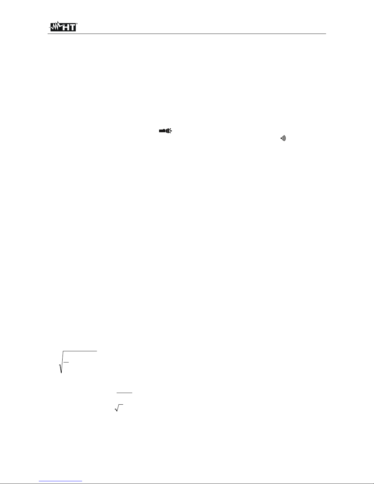
2.2. DEFINITION OF TRUE ROOT MEAN SQUARE VALUE AND CREST FACTOR
The root mean square value of current is defined as follows: “In a time equal to a period,
an alternating current with a root mean square value of 1A intensity, circulating on a
resistor, dissipates the same energy that, during the same time, would be dissipated by a
direct current with an intensity of 1A". This definition results in the numeric expression:
G=
Tt
t
dttg
T
0
0
)(
1
2
The root mean square value is indicated with the acronym RMS.
The Crest Factor is defined as the relationship between the Peak Value of a signal and its
RMS value: CF (G)=
RMS
p
G
G
This value changes with the signal waveform, for a purely
sinusoidal wave it is
2
=1.41. In case of distortion, the Crest Factor takes higher values
as wave distortion increases.
Page 6

FLASHMETER
EN - 5
3. PREPARATION FOR USE
3.1. INITIAL CHECKS
Before shipping, the instrument has been checked from an electric as well as mechanical
point of view. All possible precautions have been taken so that the instrument is delivered
undamaged. However, we recommend generally checking the instrument in order to detect
possible damage suffered during transport. In case anomalies are found, immediately
contact the forwarding agent.
We also recommend checking that the packaging contains all components indicated in §
7.3.1. In case of discrepancy, please contact the Dealer. In case the instrument should be
returned, please follow the instructions given in § 8.
3.2. INSTRUMENT POWER SUPPLY
The instrument is supplied with 2x1.5V alkaline batteries type AAA IEC LR03, included in
the package. When the battery is flat, the symbol
“ ” appears on the display. To
replace/insert the batteries, see § 6.2.
3.3. STORAGE
In order to guarantee precise measurement, after a long storage time under extreme
environmental conditions, wait for the instrument to come back to normal operating
conditions (see § 7.2.1).
Page 7

FLASHMETER
EN - 6
4. NOMENCLATURE
4.1. DESCRIPTION OF THE INSTRUMENT
CAPTION:
1. White-light torch
2. NCV sensor
3. Detector of AC voltage without
contact
4. LCD display
5. ON/OFF key
6. AutoHold/ key
7. V/Ω/ key
8. Input terminal COM
9. Input terminal V/Ω/
Fig. 1: Description of the instrument
4.2. DESCRIPTION OF THE SYMBOLS SHOWN ON THE DISPLAY
CAPTION:
1. Activated white-light torch
2. Active A HOLD function
3. Auto Power Off (APO)
4. Activation of continuity test
5. Presence of high voltage
6. Measuring unit
7. DC voltage
8. LCD display
9. AC voltage
10. Low battery symbol
Fig. 2: Description of the symbols shown on the display
Page 8

FLASHMETER
EN - 7
4.3. DESCRIPTION OF FUNCTION KEYS
4.3.1. ON/OFF key ( )
Pressing the key allows turning on the instrument. Press and hold the key for approx.
1s to turn off the instrument.
4.3.2. AutoHold/
Pressing the AutoHold/ key allows activating/deactivating the built-in white-light torch
(see Fig. 1 – part 1) and the symbol “ ” appears on the display. Press and hold the
AutoHold/
key for approx. 1s to activate/deactivate the Auto HOLD function. The
symbol
“A HOLD” appears on the display and the buzzer beeps twice in a short time. With
activated Auto HOLD function, the instrument automatically freezes the measured value
on the display when the input signal is steady (3 samplings with a maximum difference of
10% between the highest and the lowest value). The instrument automatically quits the
function after approx. 30s seconds.
4.3.3. V/Ω/ key
CAUTION
The instrument switches on in Ω mode.
The instrument automatically switches to VAC or VDC if the following
voltages are detected:
VAC > ca. 1.5V ; VDC > ca. 1.0V
The instrument automatically switches to Ω mode with the following
measured voltages:
VAC and VDC < ca. 0.6V
Press the V/Ω/ key to manually select resistance measurement and
continuity test.
4.3.4. Detection of AC voltage without contact
The instrument allows detecting the presence of AC voltage without contact by using the
NCV sensor found on the upper part (see Fig. 1 – part 2).
1. Switch on the instrument by pressing the ON/OFF key.
2. Bring the NCV sensor closer to the potential AC source.
3. If the red detector turns on (see Fig. 1 – part 3), AC voltage is present.
4.3.5. Auto-Power-Off function
In order to preserve internal batteries, the instrument switches off automatically
approximately 15 minutes after it was last used. The symbol “ ” identifies the Auto power
off function, which cannot be deactivated.
Page 9

FLASHMETER
EN - 8
5. OPERATING INSTRUCTIONS
5.1.1. DC voltage measurement
CAUTION
The maximum input DC voltage is 600V. Do not measure voltages
exceeding the limits given in this manual. Exceeding voltage limits could
result in electrical shocks to the user and damage to the instrument.
Fig. 3: Use of the instrument for DC voltage measurement
1. Switch on the instrument by pressing the ON/OFF key. The measuring mode
Ω is
automatically selected and the indication “OL.” appears on the display.
2. Insert the red cable into input terminal V/Ω/ and the black cable into input terminal
COM
3. Position the red lead and the black lead respectively in the spots with positive and
negative potential of the circuit to be measured (see Fig. 3). The instrument
automatically switches to DC voltage measurement for value > ca. 1.0V. The display
shows the value of voltage.
4. The message “O.L.” indicates that the value of DC voltage exceeds the maximum
measurable value.
5. When symbol “-” appears on the instrument’s display, it means that voltage has the
opposite direction with respect to the connection in Fig. 3.
6. To use the AutoHOLD function, see § 4.3.2
Page 10

FLASHMETER
EN - 9
5.1.2. AC voltage measurement
CAUTION
The maximum input AC voltage is 600V. Do not measure voltages
exceeding the limits given in this manual. Exceeding voltage limits could
result in electrical shocks to the user and damage to the instrument.
Fig. 4: Use of the instrument for AC voltage measurement
1. Switch on the instrument by pressing the ON/OFF key. The measuring mode Ω is
automatically selected and the indication
“OL.” appears on the display.
2. Insert the red cable into input terminal V/Ω/ and the black cable into input terminal
COM
3. Position the test leads in the desired spots of the circuit to be measured (see Fig. 4).
The instrument automatically switches to AC voltage measurement for value > ca.
1.5V. The display shows the value of voltage.
4. The message “O.L.” indicates that the value of AC voltage exceeds the maximum
measurable value.
5. To use the AutoHOLD function and the NCV sensor, see § 4.3.2 and § 4.3.4
Page 11

FLASHMETER
EN - 10
5.1.3. Resistance measurement
CAUTION
Before attempting any resistance measurement, cut off power supply from
the circuit to be measured and make sure that all capacitors are discharged,
if present.
Fig. 5: Use of the instrument for Resistance measurement
1. Switch on the instrument by pressing the ON/OFF key. The measuring mode Ω is
automatically selected and the indication “OL.” appears on the display.
2. Insert the red cable into input terminal V/Ω/ and the black cable into input terminal
COM.
3. Position the test leads in the desired spots of the circuit to be measured (see Fig. 5).
The display shows the value of resistance.
4. The message
“O.L.” indicates that the value of resistance exceeds the maximum
measurable value.
5. To use the AutoHOLD function, see § 4.3.2
Page 12

FLASHMETER
EN - 11
5.1.4. Continuity test
CAUTION
Before attempting any resistance measurement, cut off power supply from
the circuit to be measured and make sure that all capacitors are discharged,
if present.
Fig. 6: Use of the instrument for Continuity test
1. Switch on the instrument by pressing the ON/OFF key. The measuring mode Ω is
automatically selected and the indication “OL.” appears on the display.
2. Press the V/Ω/ key until the symbol “ ” appears on the display.
3. Insert the red cable into input terminal V/Ω/ and the black cable into input terminal
COM.
4. Position the test leads in the circuit to be measured (see Fig. 6). The continuity buzzer
activates for R<40
5. To use the AutoHOLD function, see § 4.3.2
Page 13

FLASHMETER
EN - 12
6. MAINTENANCE
6.1. GENERAL INFORMATION
The instrument you purchased is a precision instrument. While using and storing the
instrument, carefully observe the recommendations listed in this manual in order to
prevent possible damage or danger during use.
Do not use the instrument in environments with high humidity levels or high
temperatures. Do not expose to direct sunlight.
Always switch off the instrument after use. In case the instrument is not to be used for a
long time, remove the battery to avoid liquid leaks that could damage the instrument's
internal circuits.
6.2. REPLACING THE BATTERY
When the LCD display shows symbol “ ”, batteries must be replaced.
CAUTION
Only expert and trained technicians should perform this operation. Before
carrying out this operation, make sure you have disconnected all cables
from the input terminals.
1. Switch off the instrument by pressing the ON/OFF key.
2. Loosen the battery compartment cover fastening screw and remove the cover.
3. Remove the batteries and insert the same number of new batteries of the same type
(see § 7.1.2), respecting the indicated polarity.
4. Restore the battery compartment cover and fasten the relevant screw.
5. Do not scatter old batteries into the environment. Use the relevant containers for
disposal.
6.3. CLEANING THE INSTRUMENT
Use a soft and dry cloth to clean the instrument. Never use wet cloths, solvents, water, etc.
6.4. END OF LIFE
WARNING: the symbol on the instrument indicates that the appliance, the
battery and its accessories must be collected separately and correctly disposed
of.
Page 14

FLASHMETER
EN - 13
7. TECHNICAL SPECIFICATIONS
7.1. TECHNICAL CHARACTERISTICS
Accuracy calculated as ±[%reading + (num. digits*resol)] referred to 18°C28°C,<70%HR.
DC voltage (Autorange)
Range Resolution Accuracy Input impedance
Protection against
overcharge
400.0V
0.1V
(1.0%rdg+5digits)
>10M
Ω 600VDC/ACrms
600.0V
AC TRMS voltage (Autorange)
Range Resolution
Accuracy (*)
(40Hz 1kHz)
Input impedance
Protection against
overcharge
400.0V
0.1V
(1.0%rdg+5digits)
>9M
Ω 600VDC/ACrms
600.0V
(*) Accuracy specified from 5% to 100% of the measuring range.
Resistance (Autorange)
Range Resolution Accuracy Protection against overcharge
40.0
0.1
(2.0%rdg+18digits)
600VDC/ACrms
400.0
(2.0%rdg+10digits)
4.000k 0.001k
40.00k 0.01k
400.0k 0.1k
Continuity test with buzzer
Function Buzzer Test current
Protection against
overcharge
<40
<0.3mA 600VDC/ACrms
Page 15

FLASHMETER
EN - 14
7.1.1. Reference standards
Safety: IEC/EN61010-1
EMC: IEC/EN61326-1
Insulation: double insulation
Pollution level: 2
Overvoltage category: CAT IV 600V
Max operating altitude: 2000m (6562ft)
7.1.2. General characteristics
Mechanical characteristics
Size (L x W x H): 140 x 75 x 40mm (6 x 3 x 2in)
Weight (battery included): 220g (8 ounces)
Power supply
Battery type: 2x 1.5V batteries type AAA IEC LR03
Low battery indication: symbol “ ” on the display
Battery life: approx. 80h (backlight ON), approx. 400h
(backlight OFF)
Auto power off: after approx. 15 minutes' idling
Display
Characteristics: 4-digit LCD, 4000 dots, decimal sign and point
with backlight
Out-of-range indication: “OL.” symbol on the display
Sampling frequency: 3times/s
Conversion: TRMS
7.2. ENVIRONMENT
7.2.1. Environmental conditions for use
Reference temperature: 18°C 28°C (64°F 82°F)
Operating temperature: 0°C ÷ 50°C (32°F 122°F)
Allowable relative humidity: <75%HR
Storage temperature: -20°C ÷ 60°C (-4°F 140°F)
Storage humidity: <80%HR
Mechanical protection: IP67
Falling test: 2m (7ft)
This instrument satisfies the requirements of Low Voltage Directive 2014/35/EU
(LVD) and of EMC Directive 2014/35/EU
This instrument satisfies the requirements of European Directive 2011/65/EU (RoHS)
and 2012/19/EU (WEEE)
7.3. ACCESSORIES
7.3.1. Standard accessories
Pair of leads with 2/4mm tip
Batteries
Carrying case
User manual
Page 16

FLASHMETER
EN - 15
8. ASSISTANCE
8.1. WARRANTY CONDITIONS
This instrument is warranted against any material or manufacturing defect, in compliance
with the general sales conditions. During the warranty period, defective parts may be
replaced. However, the manufacturer reserves the right to repair or replace the product.
Should the instrument be returned to the After-sales Service or to a Dealer, transport will
be at the Customer's charge. However, shipment will be agreed in advance. A report will
always be enclosed to a shipment, stating the reasons for the product's return. Only use
original packaging for shipment; any damage due to the use of non-original packaging
material will be charged to the Customer. The manufacturer declines any responsibility for
injury to people or damage to property.
The warranty shall not apply in the following cases:
Repair and/or replacement of accessories and battery (not covered by warranty)
Repairs that may become necessary as a consequence of an incorrect use of the
instrument or due to its use together with non-compatible appliances.
Repairs that may become necessary as a consequence of improper packaging.
Repairs which may become necessary as a consequence of interventions performed
by unauthorized personnel.
Modifications to the instrument performed without the manufacturer's explicit
authorization.
Use not provided for in the instrument's specifications or in the instruction manual.
The content of this manual cannot be reproduced in any form without the manufacturer's
authorization.
Our products are patented and our trademarks are registered. The manufacturer
reserves the right to make changes in the specifications and prices if this is due to
improvements in technology.
8.2. ASSISTANCE
If the instrument does not operate properly, before contacting the After-sales Service,
please check the conditions of batteries and cables and replace them, if necessary.
Should the instrument still operate improperly, check that the product is operated
according to the instructions given in this manual. Should the instrument be returned to the
After-sales Service or to a Dealer, transport will be at the Customer's charge. However,
shipment will be agreed in advance. A report will always be enclosed to a shipment,
stating the reasons for the product's return. Only use original packaging for shipment; any
damage due to the use of non-original packaging material will be charged to the Customer.
 Loading...