

Page 1

ENGLISH
User manual
Copyright HT ITALIA 2012 Release EN 1.00 - 17/12/2012
Page 2

HT8051
Table of contents:
1. PRECAUTIONS AND SAFETY MEASURES ............................................................... 2
1.1. Preliminary instructions ......................................................................................... 2
1.2. During use ............................................................................................................. 3
1.3. After use ................................................................................................................ 3
1.4. Definition of measurement (overvoltage) category ................................................ 3
2. GENERAL DESCRIPTION ........................................................................................... 4
3. PREPARATION FOR USE ........................................................................................... 4
3.1. Initial checks .......................................................................................................... 4
3.2. Instrument power supply ....................................................................................... 4
3.3. Calibration ............................................................................................................. 4
3.4. Storage .................................................................................................................. 4
4. OPERATING INSTRUCTIONS ..................................................................................... 5
4.1. Instrument description ........................................................................................... 5
4.2. Description of function keys and initial settings ..................................................... 6
4.2.1.
4.2.2. 0-100% key .................................................................................................................. 6
4.2.3. 25%/
4.2.4. MODE key .................................................................................................................... 6
4.2.5.
4.2.6. Adjuster knob ............................................................................................................... 7
4.2.7. Setting measuring ranges for output current ................................................................ 7
4.2.8. Adjusting and disabling the Auto Power OFF function ................................................. 7
key .......................................................................................................................... 6
key .................................................................................................................. 6
key ................................................................................................................... 7
4.3. Description of measuring functions ........................................................................ 8
4.3.1. DC Voltage measurement ............................................................................................ 8
4.3.2. DC Voltage generation ................................................................................................. 9
4.3.3. DC Current measurement .......................................................................................... 10
4.3.4. DC Current generation ............................................................................................... 11
4.3.5. Measuring output DC current from external transducers (Loop) ................................ 12
4.3.6. Simulation of a transducer ......................................................................................... 13
5. MAINTENANCE ......................................................................................................... 14
5.1. General information ............................................................................................. 14
5.2. Recharging the internal battery............................................................................ 14
5.3. Cleaning the instrument ....................................................................................... 14
5.4. End of life ............................................................................................................ 14
6. TECHNICAL SPECIFICATIONS ................................................................................ 15
6.1. Technical characteristics ..................................................................................... 15
6.2. General characteristics ........................................................................................ 16
6.2.1. Reference standards .................................................................................................. 16
6.2.2. General characteristics .............................................................................................. 16
6.3. Environment ........................................................................................................ 16
6.3.1. Environmental conditions for use ............................................................................... 16
6.4. Accessories ......................................................................................................... 16
6.4.1. Accessories provided ................................................................................................. 16
7. SERVICE .................................................................................................................... 17
7.1. Warranty conditions ............................................................................................. 17
7.2. Service ................................................................................................................ 17
EN - 1
Page 3
HT8051
1. PRECAUTIONS AND SAFETY MEASURES
The instrument has been designed in compliance with directive IEC/EN61010-1 relevant to
electronic measuring instruments. For your safety and in order to prevent damaging the
instrument, please carefully follow the procedures described in this manual and read all
notes preceded by the symbol with the utmost attention.
Before and after carrying out the measurements, carefully observe the following
instructions:
Do not carry out any measurement in humid environments.
Do not carry out any measurements in case gas, explosive materials or flammables are
present, or in dusty environments.
Avoid any contact with the circuit being measured if no measurements are being
carried out.
Avoid contact with exposed metal parts, with unused measuring probes, etc.
Do not carry out any measurement in case you find anomalies in the instrument such
as deformation, substance leaks, absence of display on the screen, etc.
Never apply a voltage exceeding 30V between any pair of inputs or between an input
and the grounding in order to prevent possible electrical shocks and any damage to the
instrument.
In this manual, and on the instrument, the following symbols are used:
CAUTION: observe the instructions given in this manual; improper use could
damage the instrument or its components.
Double-insulated meter.
Connection to earth
1.1. PRELIMINARY INSTRUCTIONS
This instrument has been designed for use in environments of pollution degree 2.
It can be used to measure DC VOLTAGE and DC CURRENT.
We recommend following the normal safety rules devised to protect the user against
dangerous currents and the instrument against incorrect use.
Only the leads and the accessories supplied with the instrument guarantee complianc e
with the safety standards. They must be in good conditions and replaced with identical
models, when necessary.
Do not test circuits exceeding the specified voltage limits.
Do not perform any test under environmental conditions exceeding the limits indicated
in § 6.2.1.
Check that the battery is correctly inserted.
Before connecting the leads to the circuit being measured, check that the instrument
has been correctly set in order to prevent any damage to the instrument.
EN - 2
Page 4
HT8051
1.2. DURING USE
Please carefully read the following recommendations and instructions:
CAUTION
Failure to comply with the caution notes and/or instructions may damage
the instrument and/or its components or be a source of danger for the
operator.
Before selecting a measuring function, disconnect the test leads from the circuit under
test.
When the instrument is connected to the circuit under test, do not touch any unused
terminal.
When connecting the cables, always connect the “COM” terminal first, then the
“Positive” terminal. When disconnecting the cables, always disconnect the “Positive”
terminal first, then the “COM” terminal.
Do not apply a voltage exceeding 30V between the inputs of the instrument in
order to prevent possible damage to the instrument.
1.3. AFTER USE
When measurement is complete, press the key to switch off the instrument.
If you expect not to use the instrument for a long period, remove the battery.
1.4. DEFINITION OF MEASUREMENT (OVERVOLTAGE) CATEGORY
Standard “IEC/EN61010-1: Safety requirements for electrical equipment for measurement,
control and laboratory use, Part 1: General requirements” defines what measurement
category, commonly called overvoltage category, is. § 6.7.4: Measured circuits, reads:
(OMISSIS)
Circuits are divided into the following measurement categories:
Measurement category IV is for measurements performed at the source of the low-
voltage installation.
Examples are electricity meters and measurements on primary overcurrent protection
devices and ripple control units.
Measurement category III is for measurements performed on installations inside
buildings.
Examples are measurements on distribution boards, circuit breakers, wiring, including
cables, bus-bars, junction boxes, switches, socket-outlets in the fixed installation, and
equipment for industrial use and some other equipment, for example, stationary motors
with permanent connection to fixed installation.
Measurement category II is for measurements performed on circuits directly
connected to the low-voltage installation
Examples are measurements on household appliances, portable tools and similar
equipment.
Measurement category I is for measurements performed on circuits not directly
connected to MAINS.
Examples are measurements on circuits not derived from MAINS, and specially
protected (internal) MAINS-derived circuits. In the latter case, transient stresses are
variable; for that reason, the standard requires that the transient withstand capability of
the equipment is made known to the user.
EN - 3
Page 5

HT8051
2. GENERAL DESCRIPTION
The instrument HT8051 carries out the following measurements:
Voltage measurement up to 10V DC
Current measurement up to 24mA DC
Voltage generation with amplitude up to 100mV DC and 10V DC
Current generation with amplitude up to 24mA DC with display in mA and %
Current and voltage generation with selectable ramp outputs
Measuring output current of transducers (Loop)
Simulation of an external transducer
On the front part of the instrument there are some function keys (see § 4.2) for selecting
the type of operation. The selected quantity appears on the display with indication of the
measuring unit and the enabled functions.
3. PREPARATION FOR USE
3.1. INITIAL CHECKS
Before shipping, the instrument has been checked from an electric as well as mechanical
point of view. All possible precautions have been taken so that the instrument is delivered
undamaged.
However, we recommend generally checking the instrument in order to detect possible
damage suffered during transport. In case anomalies are found, immediately contact the
forwarding agent.
We also recommend checking that the packaging contains all components indicated in §
6.4. In case of discrepancy, please contact the Dealer.
In case the instrument should be returned, please follow the instructions given in § 7.
3.2. INSTRUMENT POWER SUPPLY
The instrument is powered by a single 1x7.4V rechargeable Li-ION battery included in the
package. The “ ” symbol appears on the display when the battery is flat. To recharge the
battery using the supplied battery charger, please refer to § 5.2.
3.3. CALIBRATION
The instrument has the technical specifications described in this manual. The instrument’s
performance is guaranteed for 12 months.
3.4. STORAGE
In order to guarantee precise measurement, after a long storage time under extreme
environmental conditions, wait for the instrument to come back to normal conditions (see §
6.2.1).
EN - 4
Page 6
HT8051
4. OPERATING INSTRUCTIONS
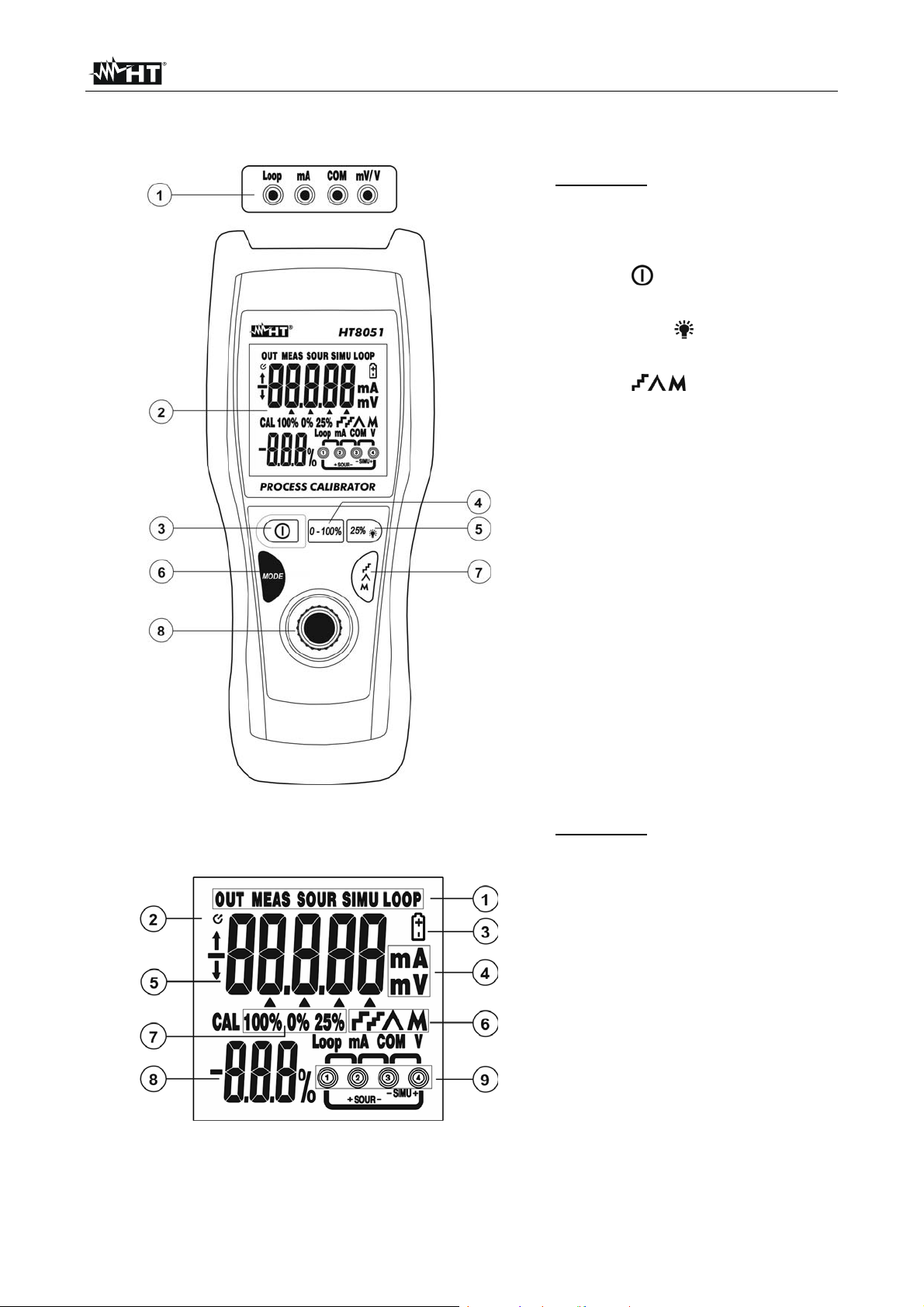
4.1. INSTRUMENT DESCRIPTION
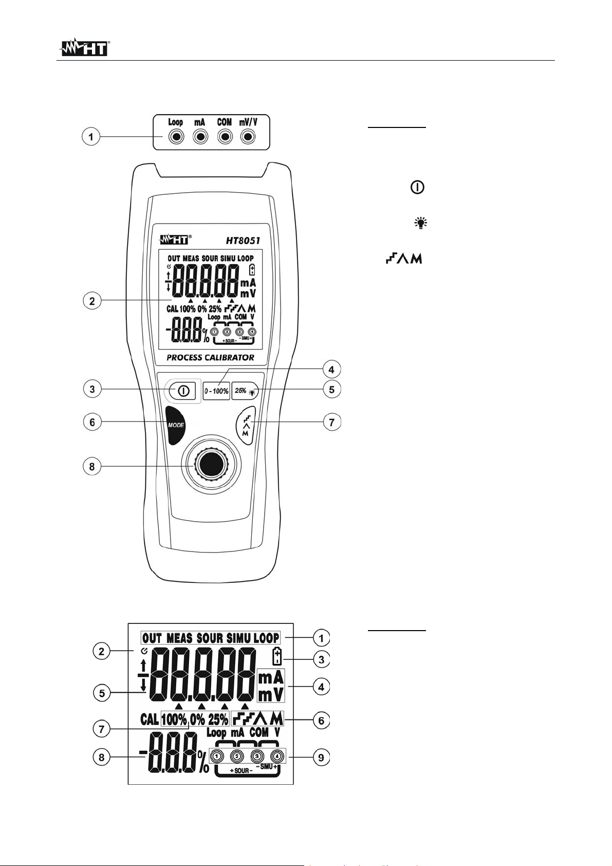
CAPTION:
1. Input terminals Loop, mA,
COM, mV/V
2. LCD display
3. Key
4. 0-100% key
5. 25%/ key
6. MODE key
7.
key
8. Adjuster knob
Fig. 1: Instrument description
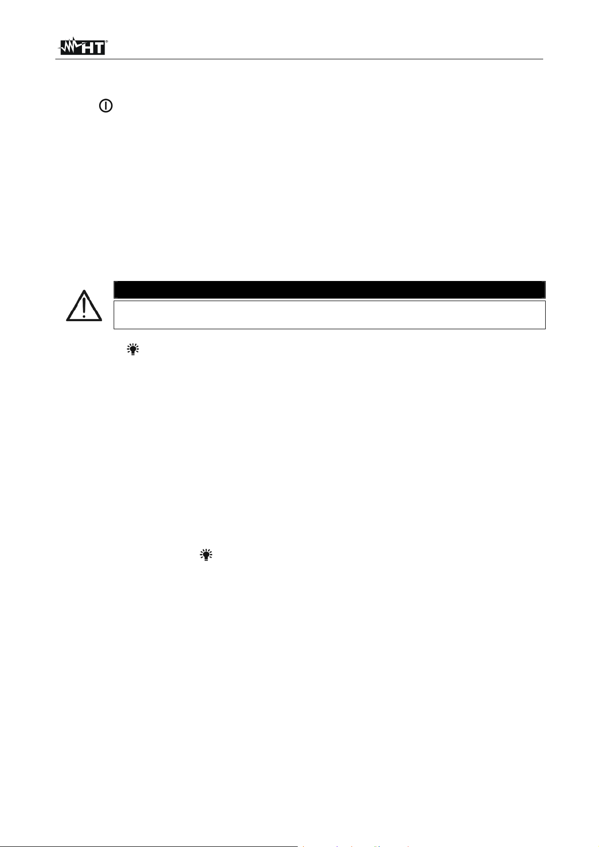
CAPTION:
1. Operating mode indicators
2. Auto Power OFF symbol
3. Low battery indication
4. Measuring unit indications
5. Main display
6. Ramp function indicators
7. Signal level indicators
8. Secondary display
9. Used inputs’ indicators
Fig. 2: Display description
EN - 5
Page 7
HT8051
4.2. DESCRIPTION OF FUNCTION KEYS AND INITIAL SETTINGS
4.2.1. key
Pressing this key turns on and off the instrument. The last selected function is indicated on
the display.
4.2.2. 0-100% key
In operating modes SOUR mA (see § 4.3.4), SIMU mA (see § 4.3.6), OUT V and OUT mV
(see § 4.3.2) pressing this key allows quickly setting the initial (0mA or 4mA) and final
(20mA) values of the output generated current, the initial (0.00mV) and final (100.00mV)
values and the initial (0.000V) and final (10.000V) values of the output generated voltage.
The percentage values “0.0%” and “100%” appear on the secondary display. The
displayed value can always be modified by using the adjuster (see § 4.2.6). The “0%” and
“100%” indication are shown at display.
CAUTION
The instrument CANNOT be used for managing measurements
(MEASURE) and signal generation (SOURCE) at the same time.
4.2.3. 25%/ key
In operating modes SOUR mA (see § 4.3.4) and SIMU mA (see § 4.3.6), OUT V and OUT
mV (see § 4.3.2), pressing this key allows quickly increasing/decreasing the value of the
generated output current/voltage in steps of 25% (0%, 25%, 50%, 75%, 100%) in the
selected measuring range. In particular, the following values are available:
Range 0 20mA 0.000mA, 5.000mA, 10.000mA, 15.000mA, 20.000mA
Range 4 20mA 4.000mA, 8.000mA, 12.000mA, 16.000mA, 20.000mA
Range 0 10V 0.000V, 2.500V, 5.000V, 7.500V, 10.000V
Range 0 100mV 0.00mV, 25.00mV, 50.00mV, 75.00mV, 100.00mV
The percentage values are shown on the secondary display and the displayed value can
always be modified by using the adjuster knob (see § 4.3.6). The “25%” indication is
shown at display.
Press and hold the 25%/
key for a 3 seconds to activate display backlighting. The
function deactivates automatically after approx. 20 seconds.
4.2.4. MODE key
Repeatedly pressing this key allows selecting the operating modes available in the
instrument. In particular, following options are available:
OUT SOUR mA generation of output current up to 24mA (see § 4.3.4).
OUT SIMU mA simulation of a transducer in a current loop with auxiliary power
supply (see § 4.3.6)
OUT V generation of output voltage up to 10V (see § 4.3.2)
OUT mV generation of output voltage up to 100mV (see § 4.3.2)
MEAS V measurement of DC voltage (max 10V) (see § 4.3.1)
MEAS mV measurement of DC voltage (max 100mV) (see § 4.3.1)
MEAS mA measurement of DC current (max 24mA) (see § 4.3.3).
MEAS LOOP mA measurement of output DC current from external transducers
(see § 4.3.5).
EN - 6
Page 8
HT8051
4.2.5. key
In operating modes SOUR mA, SIMU mA, OUT V and OUT mV pressing this key allows
setting the output current/voltage with automatic ramp, with reference to measuring ranges
0 20mA or 4 20mA for the current and 0 100mV or 0 10V for the voltage. Below
shows the available ramps.
Ramp type Description Action
Slow linear ramp Passage from 0% 100% 0% in 40s
Quick linear ramp Passage from 0% 100% 0% in 15s
Step ramp
Passage from 0% 100% 0% in steps of 25%
with ramps of 5s
Table 1: List of available ramps for output current/voltage
Press any key or turn off and then on again the instrument to exit the function.
4.2.6. Adjuster knob
In operating modes SOUR mA, SIMU mA, OUT V and OUT mV the adjuster knob (s ee
Fig. 1 – Position 8) allows programming the output current/voltage generated with
resolution 1A (0.001V/0.01mV) / 10A (0.01V/0.1mV) / 100A (0.1V/1mV). Proceed as
follows:
1. Select operating modes SOUR mA, SIMU mA, OUT V or OUT mV.
2. In case of current generation, select one of the measuring ranges 0 20mA or 4
20mA (see § 4.2.7).
3. Press the adjuster knob and set the desired resolution. The arrow symbol “” moves to
the desired position of the digits on the main display following the decimal point.
Default resolution is 1A (0.001V/0.01mV).
4. Turn the adjuster knob and set the desired value of output current/voltage. The
corresponding percentage value is indicated on the secondary display.
4.2.7. Setting measuring ranges for output current
In operating modes SOUR mA and SIMU mA it is possible to set the output range of
generated current. Proceed as follows:
1. Switch off the instrument by press the key
2. With 0-100% key pressed switch on the instrument by press the key
3. The value “0.000mA” or “4.000mA” is shown at display for approx. 3 seconds and then
the instrument back to the normal visualization
4.2.8. Adjusting and disabling the Auto Power OFF function
The instrument has an Auto Power OFF function which activates after a certain period of
idleness in order to preserve the instrument’s internal battery. The symbol “ ” appears on
the display with enabled function and the default value is 20 minutes. To set a different
time or deactivate this function, proceed as follows:
1. Press the “ ” key to switch on the instrument and, at the same time, keep the MODE
key pressed. The message “PS – XX” appears on the display for 5s. “XX” stands for
the time indicated in minutes.
2. Turn the adjuster to set the time value in the range 5 30 minutes or select “OFF” to
disable the function.
3. Wait 5s until the instrument automatically quits the function.
EN - 7
Page 9
HT8051
4.3. DESCRIPTION OF MEASURING FUNCTIONS
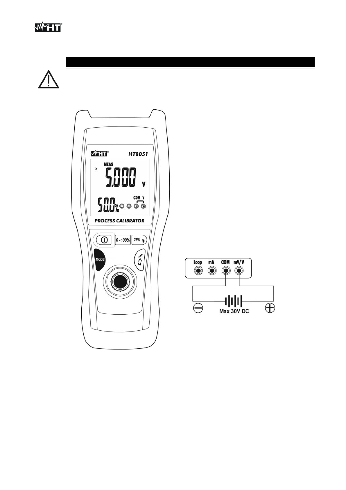
4.3.1. DC Voltage measurement
CAUTION
The maximum DC which can be applied to inputs is 30V DC. Do not
measure voltages exceeding the limits given in this manual. Exceeding
these limits could result in electrical shocks to the user and damage to the
instrument.
Fig. 3: DC voltage measurement
1. Press the MODE key and select the measuring modes MEAS V or MEAS mV. The
message “MEAS” is shown on the display
2. Insert the green cable into input lead mV/V and the black cable into input lead COM
3. Position the green lead and the black lead respectively in the points with positive and
negative potential of the circuit to be measured (see Fig. 3). The value of voltage is
shown on the main display and the percentage value with respect to the full scale on
the secondary display
4. The message “-OL-” indicates that the voltage being measured exceeds the maximum
value measurable by the instrument. The instrument do not perform voltage
measurements with opposite polarity respect to the connection in Fig. 3. The value
“0.000” is shown at display
EN - 8
Page 10
HT8051
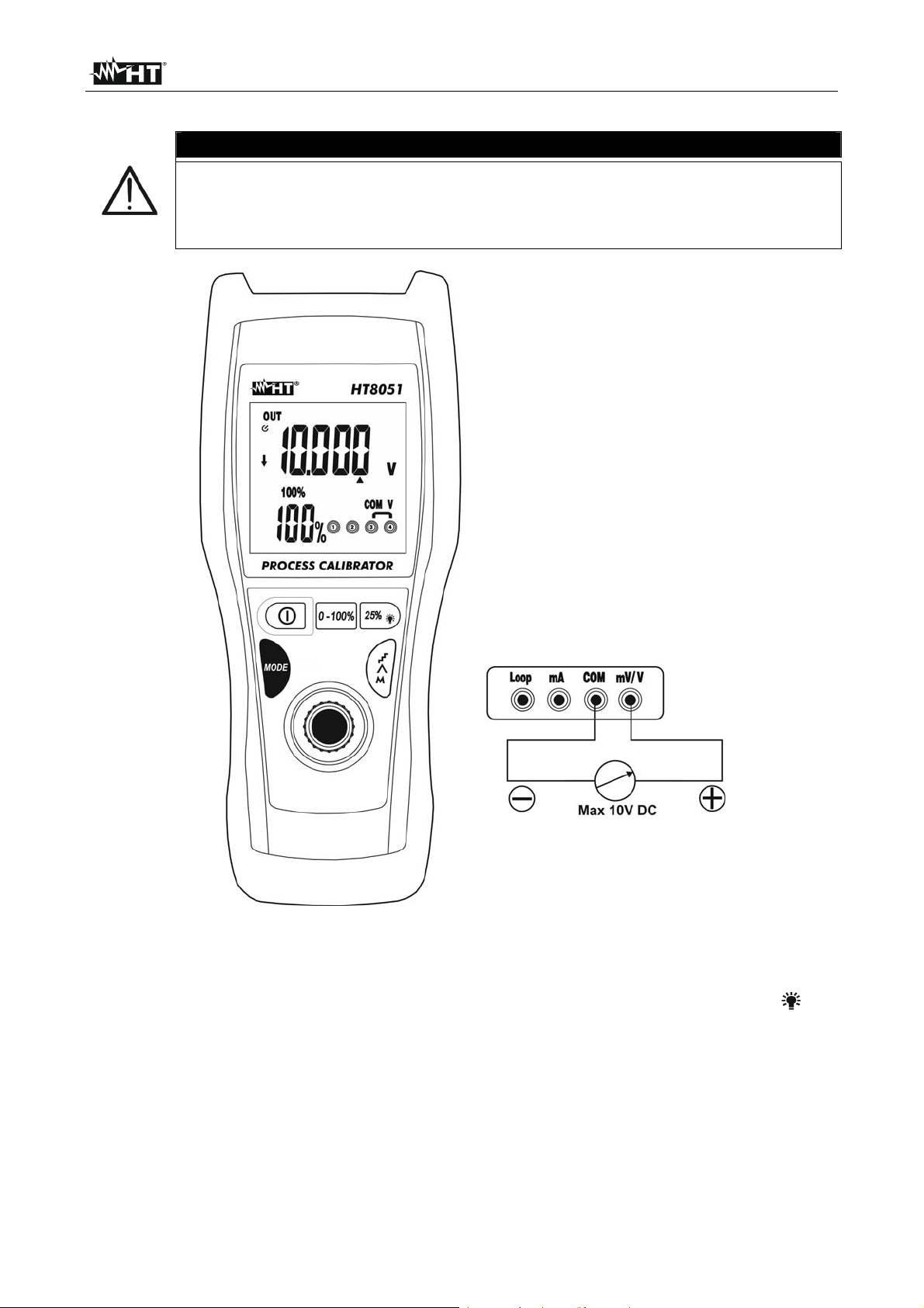
4.3.2. DC Voltage generation
The maximum DC which can be applied to inputs is 30V DC. Do not
measure voltages exceeding the limits given in this manual. Exceeding
these limits could result in electrical shocks to the user and damage to the
instrument.
CAUTION
Fig. 4: DC voltage generation
1. Press the MODE key and select modes OUT V or OUT mV. The symbol “OUT” is
shown on the display.
2. Use the adjuster knob (see § 4.2.6), the 0-100% key (see § 4.2.2) or the 25%/
key
(see § 4.2.3) to set the desired value of output voltage. The maximum values available
are 100mV (OUT mV) and 10V (OUT V). The display shows the value of voltage
3. Insert the green cable into input lead mV/V and the black cable into input lead COM.
4. Position the green lead and the black lead respectively in the points with positive and
negative potential of the external device (see Fig. 4)
5. To generate a negative voltage value, turn the measuring leads in the opposite
direction with respect to the connection in Fig. 4
EN - 9
Page 11
HT8051
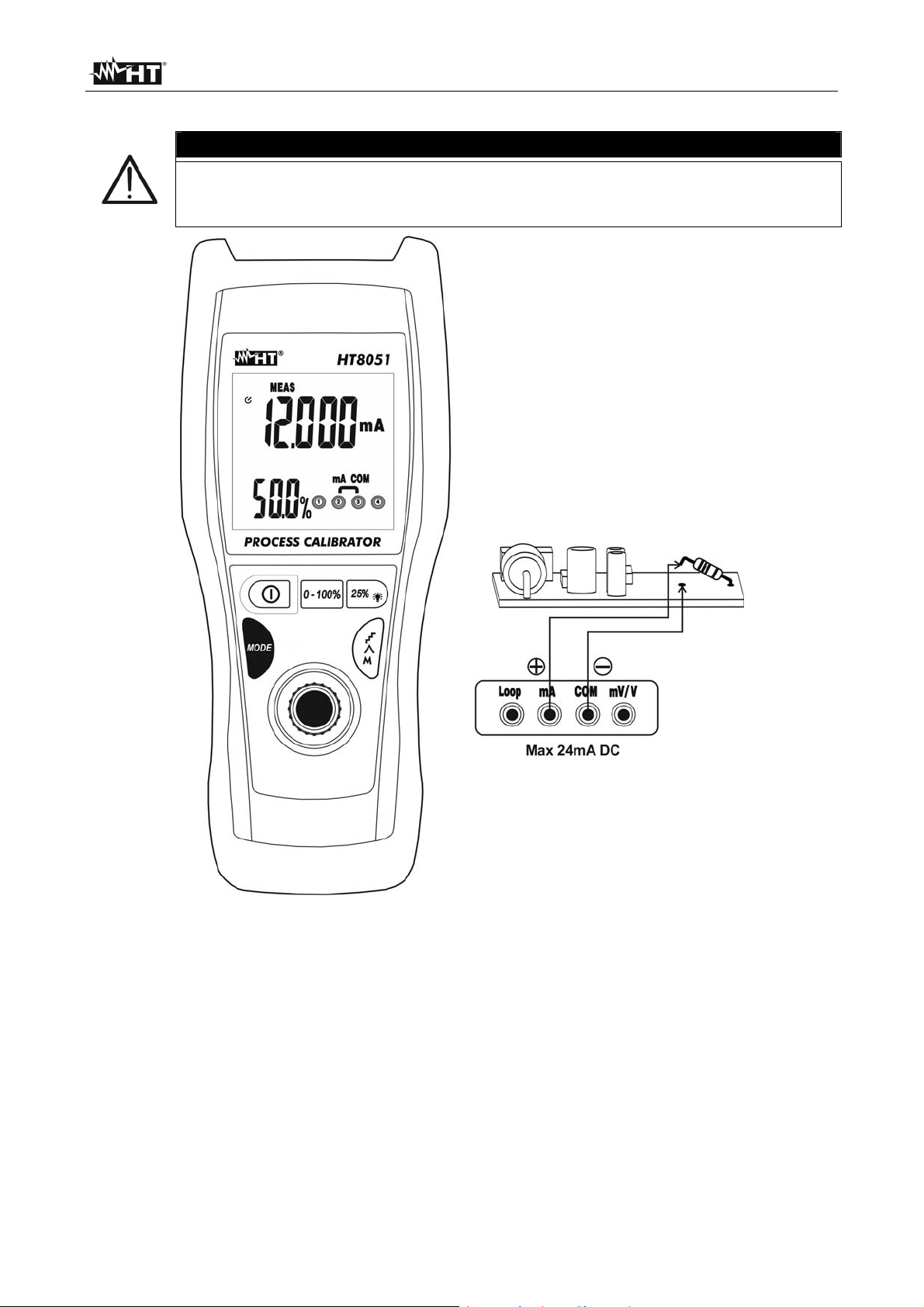
4.3.3. DC Current measurement
The maximum input DC current is 24mA. Do not measure currents
exceeding the limits given in this manual. Exceeding these limits could
result in electrical shocks to the user and damage to the instrument.
CAUTION
Fig. 5: DC current measurement
1. Cut off power supply from the circuit to be measured
2. Press the MODE key and select the measuring mode MEAS mA. The symbol “MEAS”
is shown on the display
3. Insert the green cable into the input terminal mA and the black cable into the input
terminal COM
4. Connect the green lead and the black lead in series to the circuit whose current you
want to measure, respecting polarity and current direction (see Fig. 5)
5. Supply the circuit to be measured. The value of current is shown on the main display
and the percentage value with respect to the full scale on the secondary display.
6. The message “-OL-” indicates that the current being measured exceeds the maximum
value measurable by the instrument. The instrument do not perform current
measurements with opposite polarity respect to the connection in Fig. 5. The value
“0.000” is shown at display
EN - 10
Page 12
HT8051
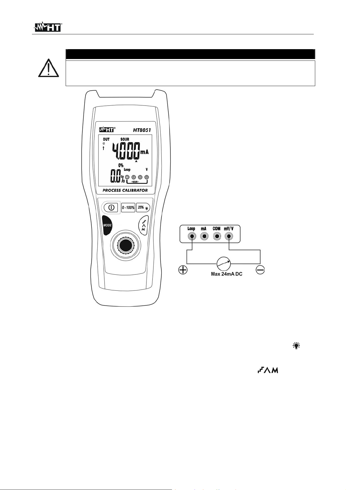
4.3.4. DC Current generation
The maximum output DC current generated on passive circuits is 24mA
With set value 0.004mA the display blink intermittently to indicate no
signal generation when the instrument is not connected to external device
CAUTION
Fig. 6: DC current generation
1. Press the MODE key and select the measuring mode SOUR mA. The symbol “SOUR”
is shown on the display
2. Define a measuring range between 0-20mA and 4-20mA (see § 4.2.7).
3. Use the adjuster knob (see § 4.2.6), the 0-100% key (see § 4.2.2) or the 25%/
key
(see § 4.2.3) to set the desired value of output current. The maximum value available is
24mA. Please consider that -25% = 0mA, 0% = 4mA, 100% = 20mA and 125% =
24mA. The display shows the value of current. If necessary, use the key (see §
4.2.5) to generate DC current with automatic ramp.
4. Insert the green cable into the input terminal Loop and the black cable into the input
terminal mV/V
5. Position the green lead and the black lead respectively in the points with positive and
negative potential of the external device which must be supplied (see Fig. 6)
6. To generate a negative current value, turn the measuring leads in the opposite
direction with respect to the connection in Fig. 6
EN - 11
Page 13
HT8051
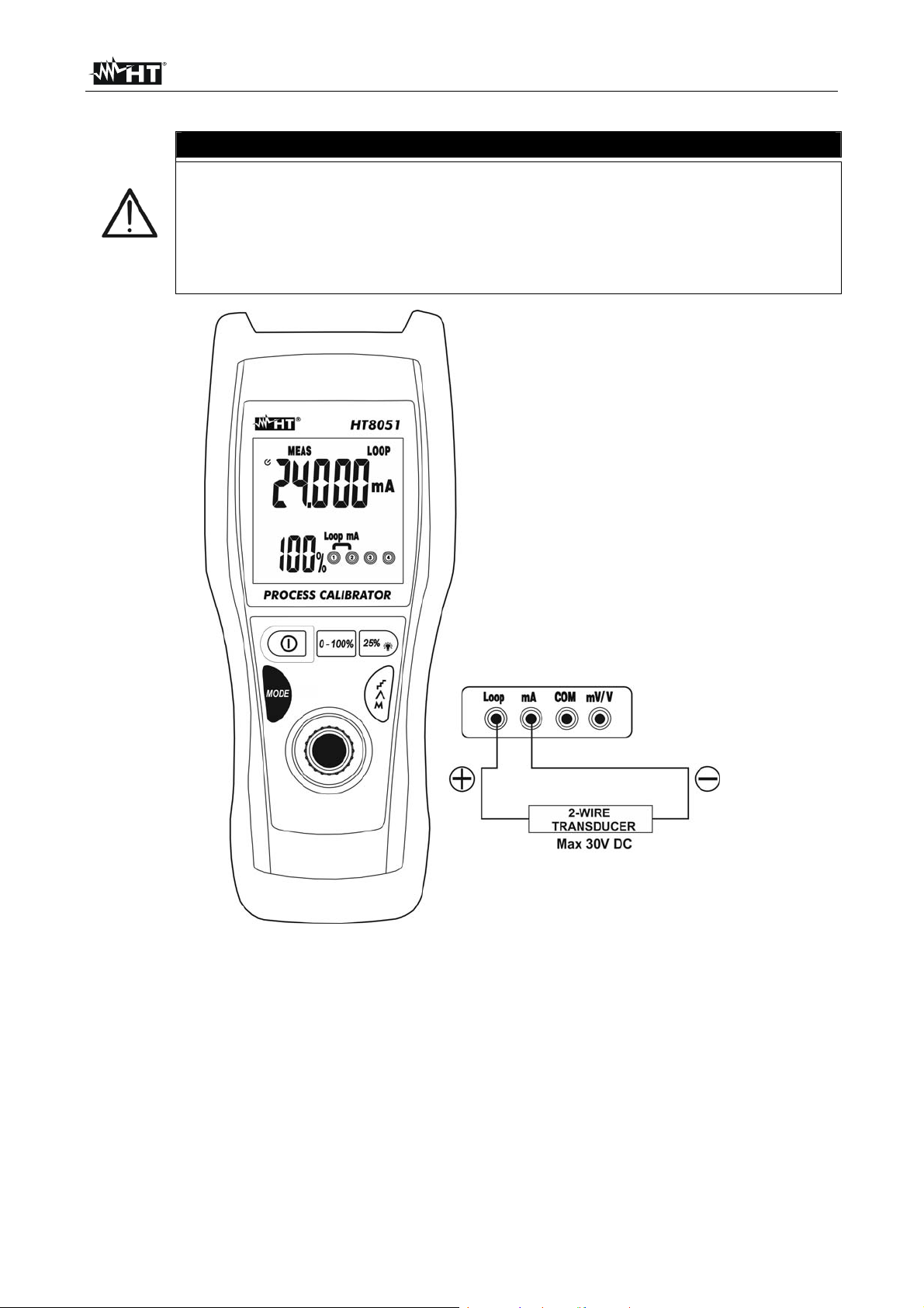
4.3.5. Measuring output DC current from external transducers (Loop)
CAUTION
In this mode, the instrument provides a fixed output voltage of
25VDC±10% capable of supplying an external transducer and allowing
measuring current at the same time.
The maximum output DC current is 24mA. Do not measure currents
exceeding the limits given in this manual. Exceeding these limits could
result in electrical shocks to the user and damage to the instrument.
Fig. 7: Measuring output DC current from external transducers (Loop)
1. Cut off power supply from the circuit to be measured
2. Press the MODE key and select the measuring mode MEAS LOOP mA. Symbols
“MEAS” and “LOOP” appear on the display.
3. Insert the green cable into the input terminal Loop and the black cable into the input
terminal mA
4. Connect the green lead and the black lead to the external transducer, respecting
current polarity and direction (see Fig. 7).
5. Supply the circuit to be measured. The display shows the value of current.
6. The message “-OL-” indicates that the current being measured exceeds the maximum
value measurable by the instrument. To generate a negative voltage value, turn the
measuring leads in the opposite direction with respect to the connection in Fig. 7
EN - 12
Page 14
HT8051
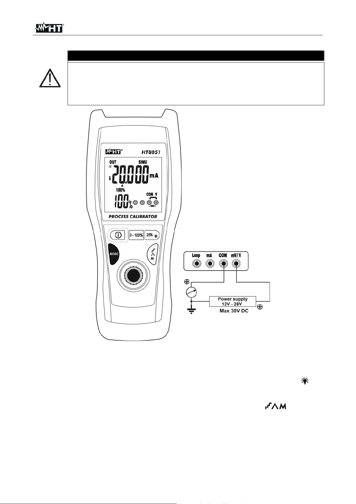
4.3.6. Simulation of a transducer
In this mode, the instrument provides an adjustable output current up to
24mADC. It is necessary to provide an external power supply with voltage
between 12V and 28V in order to adjust current
With set value 0.004mA the display blink intermittently to indicate no
signal generation when the instrument is not connected to external device
CAUTION
Fig. 8: Simulation of a transducer
1. Press the MODE key and select the measuring mode SIMU mA. Symbols “ OUT” and
“SOUR” appear on the display.
2. Define a measuring range of current between 0-20mA and 4-20mA (see § 4.2.7).
3. Use the adjuster knob (see § 4.2.6), the 0-100% key (see § 4.2.2) or the 25%/ key
(see § 4.2.3) to set the desired value of output current. The maximum value available is
24mA. Please consider that -25% = 0mA, 0% = 4mA, 100% = 20mA and 125% =
24mA. The display shows the value of current. If necessary, use the key (see §
4.2.5) to generate DC current with automatic ramp.
4. Insert the green cable into input lead mV/V and the black cable into input lead COM.
5. Position the green lead and the black lead respectively in the points with positive
potential of the external source and positive potential of the external measuring device
(e.g.: multimeter – see Fig. 8)
6. To generate a negative current value, turn the measuring leads in the opposite
direction with respect to the connection in Fig. 8
EN - 13
Page 15
HT8051
5. MAINTENANCE
5.1. GENERAL INFORMATION
1. The instrument you purchased is a precision instrument. While using and storing the
instrument, carefully observe the recommendations listed in this manual in order to
prevent possible damage or danger during use.
2. Do not use the instrument in environments with high humidity levels or high
temperatures. Do not expose to direct sunlight.
3. Always switch off the instrument after use. In case the instrument is not to be used for
a long time, remove the batteries to avoid liquid leaks that could damage the
instrument’s internal circuits.
5.2. RECHARGING THE INTERNAL BATTERY
When the LCD displays the symbol " ", it is necessary to recharge the internal battery.
Only expert and trained technicians should perform maintenance
operations.
1. Switch off the instrument using the key
2. Connect the battery charger to the 230V/50Hz electric mains.
3. Insert the red cable of the charger into terminal Loop and the black cable into terminal
COM. The instrument switch on the backlight in fixed mode and the charging process
start
4. The charging process is finished when the backlight is blinking at display. This
operation have a duration time of approx. 4 hours
5. Disconnect the battery charger at the end of the operation.
The Li-ION battery must always be recharged whenever the instrument is
used, in order not to shorten its duration. The instrument may also operate
with a 1x9V alkaline battery type NEDA1604 006P IEC6F22. Do not
connect the battery charger to the instrument when it is supplied by
an alkaline battery.
Immediately disconnect the cable from the electrical mains in case of
overheating of instrument parts during battery recharge
If the battery voltage is too low (<5V), the backlight may not switch on. Still
continue the process in the same way
5.3. CLEANING THE INSTRUMENT
Use a soft and dry cloth to clean the instrument. Never use wet cloths, solvents, water, etc.
5.4. END OF LIFE
CAUTION: this symbol found on the instrument indicates that the appliance, its
accessories and the battery must be collected separately and correctly disposed
of.
CAUTION
CAUTION
EN - 14
Page 16

HT8051
6. TECHNICAL SPECIFICATIONS
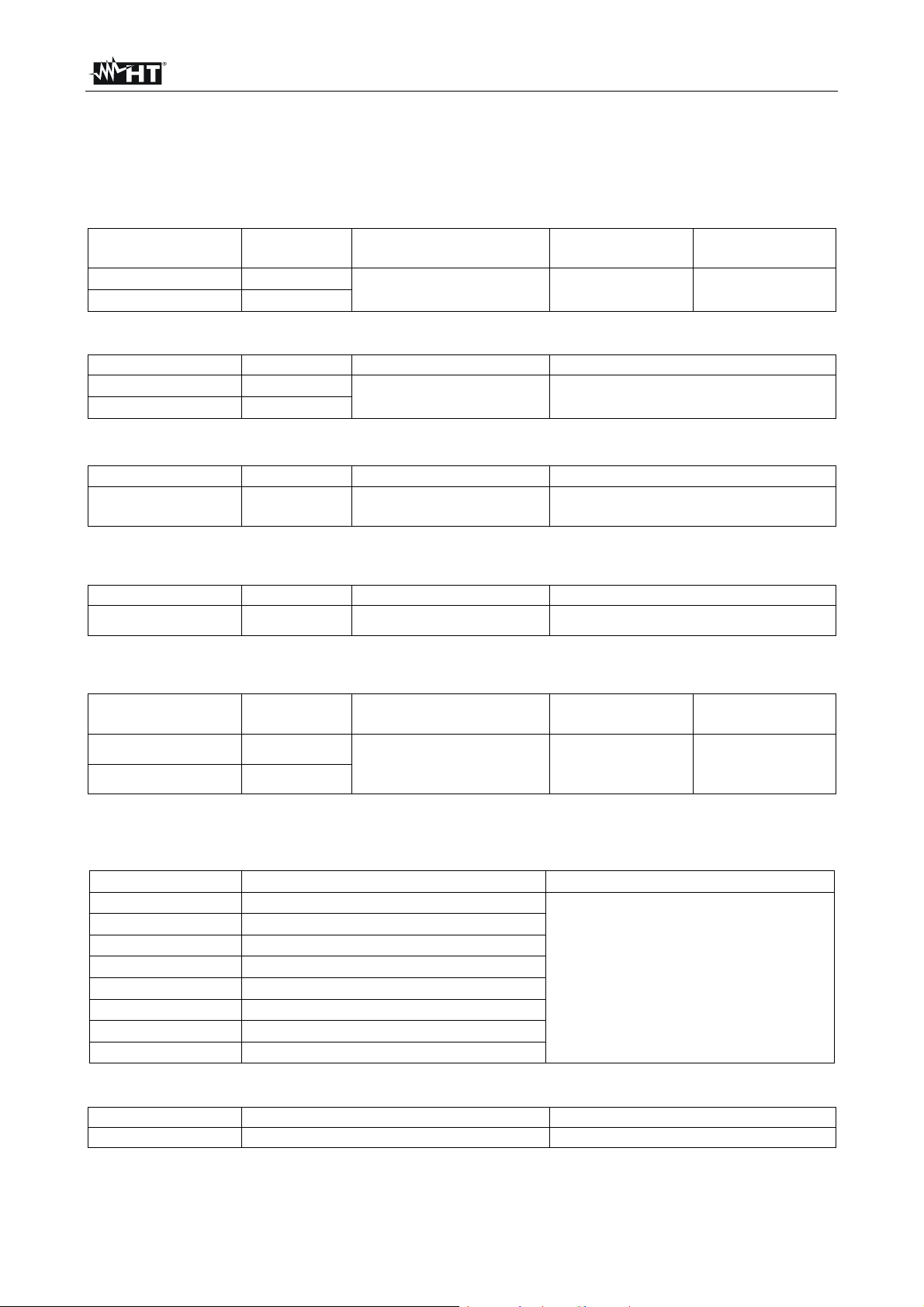
6.1. TECHNICAL CHARACTERISTICS
Accuracy is calculated as [%reading + (no. of digits) * resolution] at 18°C 28°C, <75%RH
Measured DC voltage
Protection
Range Resolution Accuracy Input impedance
0.01100.00mV
0.00110.000V
0.01mV
0.001V
(0.02rdg +4digits) 1M
Generated DC voltage
Range Resolution Accuracy Protection against overcharge
0.01100.00mV
0.00110.000V
0.01mV
0.001V
(0.02rdg +4digits)
30VDC
Measured DC current
Range Resolution Accuracy Protection against overcharge
0.00124.000mA
Sampling resistance: 10
0.001mA
(0.02%rdg + 4digits)
with 100mA integrated fuse
max 50mADC
Measured DC current with Loop function
Range Resolution Accuracy Protection against overcharge
0.00124.000mA
Sampling resistance: 10
0.001mA
(0.02%rdg + 4digits)
max 30mADC
Generated DC current (SOUR and SIMU functions)
Range Resolution Accuracy
0.00124.000mA
0.001mA
(0.02%rdg + 4digits)
-25.00 125.00%
SOUR mA mode maximum allowed load :1k @ 20mA
SIMU mA mode loop voltage: 24V rated, 28V maximum, 12V minimum
0.01%
Percentage
values
0% = 4mA
100% = 20mA
125% = 24mA
SIMU Mode reference parameters
Loop voltage Generated current Load resistance
12V 11mA
14V 13mA
16V 15mA
18V 17mA
20V 19mA
0.8k
22V 21mA
24V 23mA
25V 24mA
Loop mode (loop current)
Range Resolution Protection against overcharge
25VDC ±10% Not specified 30VDC
against
overcharge
30VDC
Protection
against
overcharge
max 24mADC
EN - 15
Page 17
HT8051
6.2. GENERAL CHARACTERISTICS
6.2.1. Reference standards
Safety: IEC/EN 61010-1
Insulation: double insulation
Pollution level: 2
Measurement category: CAT I 30V
Max operating altitude: 2000m
6.2.2. General characteristics
Mechanical characteristics
Size (L x W x H): 195 x 92 x 55mm
Weight (battery included): 400g
Display
Characteristics: 5 LCD, decimal sign and point
Over range indication: the display shows message “-OL-”
Power supply
Rechargeable battery 1x7.4/8.4V 700mAh Li-ION
Alkaline battery: 1x9V type NEDA1604 006P IEC6F22
External adapter: 230VAC/50Hz – 12VDC/1A
Battery life: SOUR mode: approx. 8 hours (@ 12mA, 500)
MEAS/SIMU mode: approx. 15 hours
Low battery indication: the display shows symbol “ ”
Auto power off: after 20 minutes (adjustable) of non-operation
6.3. ENVIRONMENT
6.3.1. Environmental conditions for use
Reference temperature: 18°C 28°C
Operating temperature: -10 ÷ 40°C
Allowable relative humidity: <95%RH up to 30°C, <75%RH up to 40°C
<45%RH up to 50°C, <35%RH up to 55°C
Storage temperature: -20 ÷ 60°C
This instrument satisfies the requirements of Low Voltage Directive 2006/95/EC
(LVD) and of EMC Directive 2004/108/EC
6.4. ACCESSORIES
6.4.1. Accessories provided
Pair of test leads
Pair of alligator clips
Protection shell
Rechargeable battery (not inserted)
External battery charger
User manual
Hard carrying case
EN - 16
Page 18

HT8051
7. SERVICE
7.1. WARRANTY CONDITIONS
This instrument is warranted against any material or manufacturing defect, in compliance
with the general sales conditions. During the warranty period, defective parts may be
replaced. However, the manufacturer reserves the right to repair or replace the product.
Should the instrument be returned to the After-sales Service or to a Dealer, transport will
be at the Customer’s charge. However, shipment will be agreed in advance.
A report will always be enclosed to a shipment, stating the reasons for the product’s return.
Only use original packaging for shipment; any damage due to the use of non-original
packaging material will be charged to the Customer.
The manufacturer declines any responsibility for injury to people or damage to property.
The warranty shall not apply in the following cases:
Repair and/or replacement of accessories and battery (not covered by warranty).
Repairs that may become necessary as a consequence of an incorrect use of the
instrument or due to its use together with non-compatible appliances.
Repairs that may become necessary as a consequence of improper packaging.
Repairs which may become necessary as a consequence of interventions performed
by unauthorized personnel.
Modifications to the instrument performed without the manufacturer’s explicit
authorization.
Use not provided for in the instrument’s specifications or in the instruction manual.
The content of this manual cannot be reproduced in any form without the manufacturer’s
authorization.
Our products are patented and our trademarks are registered. The manufacturer
reserves the right to make changes in the specifications and prices if this is due to
improvements in technology.
7.2. SERVICE
If the instrument does not operate properly, before contacting the After-sales Service,
please check the conditions of battery and cables and replace them, if necessary.
Should the instrument still operate improperly, check that the product is operated
according to the instructions given in this manual.
Should the instrument be returned to the After-sales Service or to a Dealer, transport will
be at the Customer’s charge. However, shipment will be agreed in advance.
A report will always be enclosed to a shipment, stating the reasons for the product’s return.
Only use original packaging for shipment; any damage due to the use of non-original
packaging material will be charged to the Customer.
EN - 17
Page 19

ESPAÑOL
Manual de instrucciones
Copyright HT ITALIA 2012 Versión ES 1.00 - 17/12/2012
Page 20
HT8051
Índice:
1. PRECAUCIONES Y MEDIDAS DE SEGURIDAD ........................................................ 2
1.1. Instrucciones preliminares ..................................................................................... 2
1.2. Durante la utilización ............................................................................................. 3
1.3. Después de la utilización ....................................................................................... 3
1.4. Definición de Categoría de medida (Sobretensión) ............................................... 3
2. DESCRIPCIÓN GENERAL ........................................................................................... 4
3. PREPARACIÓN A LA UTILIZACIÓN ............................................................................ 4
3.1. Controles iniciales ................................................................................................. 4
3.2. Alimentación del instrumento ................................................................................ 4
3.3. Calibración ............................................................................................................ 4
3.4. Conservación ......................................................................................................... 4
4. INSTRUCCIONES OPERATIVAS ................................................................................ 5
4.1. Descripción del instrumento .................................................................................. 5
4.2. Descripción teclas función y configuraciones iniciales .......................................... 6
4.2.1. Tecla
4.2.2. Tecla 0-100% ............................................................................................................... 6
4.2.3. Tecla 25%/
4.2.4. Tecla MODE ................................................................................................................. 6
4.2.5. Tecla
4.2.6. Selector de regulación ................................................................................................. 7
4.2.7. Configuración de los escalas de medida de corriente de salida .................................. 7
4.2.8. Regulación y deshabilitación de la función Autoapagado ............................................ 7
....................................................................................................................... 6
............................................................................................................... 6
................................................................................................................ 7
4.3. Descripción de las funciones de medida ............................................................... 8
4.3.1. Medida de Tensión CC ................................................................................................ 8
4.3.2. Generación de Tensión CC .......................................................................................... 9
4.3.3. Medida de Corriente CC ............................................................................................ 10
4.3.4. Generación de Corriente CC ...................................................................................... 11
4.3.5. Medida de corriente CC en salida de transductores externos (Loop) ........................ 12
4.3.6. Simulación de un transductor ..................................................................................... 13
5. MANTENIMIENTO ...................................................................................................... 14
5.1. Generalidades ..................................................................................................... 14
5.2. Carga de la batería interna .................................................................................. 14
5.3. Limpieza del instrumento ..................................................................................... 14
5.4. Fin de vida ........................................................................................................... 14
6. ESPECIFICACIONES TÉCNICAS .............................................................................. 15
6.1. Características técnicas ...................................................................................... 15
6.2. Características generales .................................................................................... 16
6.2.1. Normas de referencia ................................................................................................. 16
6.2.2. Características generales .......................................................................................... 16
6.3. Ambiente ............................................................................................................. 16
6.3.1. Condiciones ambientales de utilización ..................................................................... 16
6.4. Accesorios ........................................................................................................... 16
6.4.1. Accesorios en dotación .............................................................................................. 16
7. ASISTENCIA .............................................................................................................. 17
7.1. Condiciones de garantía ...................................................................................... 17
7.2. Asistencia ............................................................................................................ 17
ES - 1
Page 21
HT8051
1. PRECAUCIONES Y MEDIDAS DE SEGURIDAD
El instrumento ha sido diseñado en conformidad con la directiva IEC/EN61010-1, relativa
a los instrumentos de medida electrónicos. Por su seguridad y para evitar daños en el
equipo, le rogamos que siga los procedimientos descritos en el presente manual y que lea
con particular atención todas las notas precedidas por el símbolo .
Antes y durante la ejecución de las medidas aténgase escrupulosamente a las siguientes
indicaciones:
No efectúe medidas en ambientes húmedos.
No efectúe medidas en presencia de gas o materiales explosivos, combustibles o en
presencia de polvo.
Evite contactos con el circuito en examen si no están efectuando medidas.
Evite contactos con partes metálicas expuestas, con terminales de medida no
utilizados, etc.
No efectúe ninguna medida si encontrara alguna anomalía en el instrumento como,
deformaciones, salida de sustancias, ausencia de visualización en la pantalla, etc.
No aplique nunca una tensión superior a 30V entre cada par de entradas o entre
cada entrada y la referencia de tierra a fin de evitar posibles shock eléctricos y/o daños
en el instrumento
En el presente manual y en el instrumento se utilizan los siguientes símbolos:
Atención: aténgase a las instrucciones reportadas en el manual; un uso
incorrecto podría causar daños en el instrumento o en sus componentes.
Instrumento con doble aislamiento.
Referencia de tierra
1.1. INSTRUCCIONES PRELIMINARES
Este instrumento ha sido diseñado para una utilización en un ambiente con nivel de
polución 2
Puede ser utilizado para medidas de TENSIÓN CC y CORRIENTE CC
Le invitamos a seguir las normales reglas de seguridad orientadas a protegerlo contra
corrientes peligrosas y a proteger el instrumento contra una utilización equivocada.
Sólo las puntas y los accesorios suministrados en dotación del instrumento garantizan
los estándares de seguridad. Estos deben ser en buenas condiciones y sustituidos, si
fuera necesario, con modelos idénticos
No efectúe medidas sobre circuitos que superen los límites de corriente especificados.
No efectúe medidas en condiciones ambientales más allá de las indicadas en el §
6.2.1
Controle que la batería esté correctamente insertadas
Antes de conectar las puntas en el circuito en examen, controle la correcta
funcionalidad de medida a fin de evitar posibles daños al instrumento
ES - 2
Page 22

HT8051
1.2. DURANTE LA UTILIZACIÓN
Le rogamos que lea atentamente las recomendaciones y las instrucciones siguientes:
ATENCIÓN
La falta de observación de las advertencias y/o instrucciones puede dañar
al instrumento y/o sus componentes o ser fuente de peligro para el
operador.
Antes de seleccionar una función de medida, desconecte las puntas de prueba del
circuito en examen
Cuando el instrumento esté conectado al c ircuito en examen no toque nunca ninguno
de los terminales no utilizados
Durante las conexiones conecte antes el terminal “COM” que el terminal “Positivo”. En
la fase opuesta desconecte antes el terminal “Positivo” y luego el terminal “COM”
No aplique una tensión superior a 30V entre las entradas del instrumento a fin de
evitar posibles daños en el instrumento
1.3. DESPUÉS DE LA UTILIZACIÓN
Cuando termine las medidas pulse la tecla para apagar el instrumento
Si prevé no utilizar el instrumento por un largo período de tiempo retire la batería
1.4. DEFINICIÓN DE CATEGORÍA DE MEDIDA (SOBRETENSIÓN)
La norma IEC/EN61010-1: Prescripciones de seguridad para instrumentos eléctricos de
medida, control y para utilización en laboratorio, Parte 1: Prescripciones generales, define
lo que se entiende por categoría de medida, comúnmente llamada categoría de
sobretensión. En § 6.7.4: Circuitos de medida, esta dice:
(OMISSIS)
Los circuitos están divididos en las siguientes categorías de medida:
La categoría de medida IV sirve para las medidas efectuadas sobre una fuente de
una instalación a baja tensión
Como ejemplo los contadores eléctricos y de medida sobre dispositivos primarios de
protección de sobrecorrientes y sobre las unidades de regulación de la ondulación
La categoría de medida III sirve para las medidas efectuadas en instalaciones en el
interior de edificios
Por ejemplo medidas sobre paneles de distribución, disyuntores, cableado,
comprendidos los cables, las barras, las cajas de empalme, los interruptores, las tomas
de instalaciones fijas y los instrumentos destinados al empleo industrial y otras
instrumentaciones, por ejemplo los motores fijos con conexión a una instalación fija
La categoría de medida II sirve para las medidas efectuadas sobre circuitos
conectados directamente a una instalación de baja tensión
Por ejemplo medidas sobre instrumentaciones para uso domestico, utensilios portátiles
e instrumentos similares
La categoría de medida l sirve para las medidas efectuadas sobre circuitos no
conectados directamente a la RED de DISTRIBUCIÓN
Por ejemplo medidas sobre no derivados de la RED y derivados de la RED pero con
protección propia (interna). En este último caso las peticiones de transistores son
variables, por este motivo (OMISSIS) se requiere que el usuario conozca la capacidad
de los transistores de la instrumentación
ES - 3
Page 23

HT8051
2. DESCRIPCIÓN GENERAL
El instrumento HT8051 tiene las siguientes características:
Medida de tensión hasta 10V CC
Medida de corriente hasta 24mA CC
Generación de tensión con amplitud hasta 100mV CC y 10V CC
Generación con amplitud hasta 24mA CC con visualización en mA y %
Generación tensión y corriente con salidas en rampa seleccionables
Medida de corriente en salida de transductores (Loop)
Simulación de un transductor externo
Sobre la parte frontal existen algunas teclas de función (vea el § 4.2) para la selección del
tipo de operación. La magnitud seleccionada aparece en pantalla con indicaciones de la
unidad de medida y de las funciones habilitadas.
3. PREPARACIÓN A LA UTILIZACIÓN
3.1. CONTROLES INICIALES
El instrumento, antes de ser enviado, ha sido controlado desde el punto de vista eléctrico
y mecánico. Han sido tomadas todas las precauciones posibles para que el instrumento
pueda ser entregado sin daños.
Aún así se aconseja, que contrale someramente el instrumento para descartar eventuales
daños sufridos durante el transporte. Si se encontraran anomalías contacte
inmediatamente al distribuidor.
Comprueba que el embalaje contenga todas las partes indicadas en el § 6.4 . En caso de
discrepancia contacte con el distribuidor.
Si fuera necesario devolver el instrumento, si ruega que siga las instrucciones reportadas
en el parágrafo § 7.
3.2. ALIMENTACIÓN DEL INSTRUMENTO
El instrumento se alimenta mediante una batería 1x7.4V recargable de Li-ION incluida en
el embalaje. Cuando la batería está descargada aparece en el visualizador el símbolo " ".
Para cargar la pila vea el § 5.2
3.3. CALIBRACIÓN
El instrumento refleja las características técnicas reportadas en el presente manual. Las
prestaciones del instrumento tienen garantía de un año.
3.4. CONSERVACIÓN
Para garantizar medidas precisas, después de un largo período de almacenamiento en
condiciones ambientales extremas, espere a que el instrumento vuelva a las condiciones
normales (vea el § 6.2.1).
ES - 4
Page 24
HT8051
4. INSTRUCCIONES OPERATIVAS
4.1. DESCRIPCIÓN DEL INSTRUMENTO
LEYENDA:
1. Terminales de entrada Loop,
mA, COM, mV/V
2. Visualizador LCD
3. Tecla
4. Tecla 1-100%
5. Tecla 25%/
6. Tecla MODE
7. Tecla
8. Selector de regulación
Fig. 1: Descripción del instrumento
LEYENDA:
1. Indicadores de modos de
función
2. Símbolo de Autoapagado
3. Indicación de batería
descargada
4. Indicaciones de unidad de
medida
5. Visualizador principal
6. Indicador de funciones de
Rampa
7. Indicadores del nivel de la
señal
8. Visualizador secundario
9. Indicadores de entradas
Fig. 2: Descripción del visualizador
ES - 5
Page 25

HT8051
4.2. DESCRIPCIÓN TECLAS FUNCIÓN Y CONFIGURACIONES INICIALES
4.2.1. Tecla
Esta tecla permite encender/apagar el instrumento con una simple pulsación. La
referencia de la última función seleccionada aparece en el visualizador
4.2.2. Tecla 0-100%
En los modos de funcionamiento SOUR mA (vea § 4.3.4), SIMU mA (vea § 4.3.6), OUT V
y OUT mV (vea § 4.3.2) la pulsación de esta tecla permite la configuración rápida de los
valores inicial (0mA o 4mA) y final (20mA) de la corriente generada en salida, el valor
inicial (0.00mV) y final (100.00mV) y el valor inicial (0.000V) y final (10.000V) de la tensión
generada en salida. Los valores porcentuales “0.0%” y “100%” se muestran en el
visualizador secundario. El valor visualizado puede ser siempre modificado mediante el
selector de regulación (vea § Errore. L'origine riferimento non è stata trovata.). Las
indicaciones “0%” y “100%” se muestran en el visualizador.
ATENCIÓN
El instrumento NO puede ser utilizado para la gestión simultánea de
las operaciones de medida (MEASURE) y generación de las señales
(SOURCE)
4.2.3. Tecla 25%/
En los modos de funcionamiento SOUR mA (vea § 4.3.4) y SIMU mA (vea § 4.3.6), OUT
V y OUT mV (vea § 4.3.2) la pulsación de esta tecla permite incrementar y disminuir
rápidamente el valor de la corriente/tensión generada en salida en pasos de 25% (0%,
25%, 50%, 75%, 100%) del escala de medida seleccionado. En particular están
disponibles los valores:
Escala 0 20mA 0.000mA, 5.000mA, 10.000mA, 15.000mA, 20.000mA
Escala 4 20mA 4.000mA, 8.000mA, 12.000mA, 16.000mA, 20.000mA
Escala 0 10V 0.000V, 2.500V, 5.000V, 7.500V, 10.000V
Escala 0 100mV 0.00mV, 25.00mV, 50.00mV, 75.00mV, 100.00mV
Los valores porcentuales se muestran en el visualizador secundario y el valor en pantalla
siempre puede ser modificado mediante el selector de regulación (vea § 4.3.6)
Mantenga pulsada la tecla 25%/
durante 3 segundos para activar la retroiluminación del
visualizador. La función se deshabilita automáticamente después de aprox. 20 segundos.
4.2.4. Tecla MODE
La pulsación cíclica de esta tecla permite la selección de los modos de funcionamiento
que el instrumento tiene disponible. En particular son posibles las siguientes opciones:
OUT SOUR mA generación de la corriente de salida hasta 24mA (vea § 4.3.4)
OUT SIMU mA simulación de un transductor en un anillo de corriente con
alimentación auxiliar (vea § 4.3.6)
OUT V generación de tensión CC en salida hasta 10V (vea § 4.3.2)
OUT mV generación de tensión CC en salida hasta 100mV CC (vea § 4.3.2)
MEAS V medida de tensión CC (max 10V) (vea § 4.3.1)
MEAS mV medida de tensión CC (max 100mV) (vea § 4.3.1)
MEAS mA medida de corriente CC (max 24mA) (vea § 4.3.3)
MEAS LOOP mA medida de corriente CC de salida de transductores (vea § 4.3.5)
ES - 6
Page 26

HT8051
4.2.5. Tecla
En los modos de funcionamiento SOUR mA, SIMU mA, OUT V y OUT mV la pulsación de
esta tecla permite la configuración de la corriente/tensión de salida con rampa automática,
relativa a los escalas de medida 0 20mA o 4 20mA para la corriente y 0 100mV o 0
10V para la tensión. Las rampas disponibles se muestran en la siguiente Tabla 1
Tipo rampa Descripción Acción
Pulse cualquier tecla o apague y encienda el instrumento para salir de la función
Tabla 1 : Listado de rampas disponibles para la corriente de salida
Rampa lenta lineal Paso de 0% 100% 0% en 40s
Rampa rápida lineal Paso de 0% 100% 0% en 15s
Rampa en escalón
Paso de 0% 100% 0% en pasos de 25%
con rampas de 5s
4.2.6. Selector de regulación
En los modos de funcionamiento SOUR mA, SIMU mA, OUT V y OUT mV el selector de
regulación (vea Fig. 1 – Posición 8) permite ejecutar una programación fina de la
corriente/tensión en salida generada con resoluciones 1A (0.001V/0.01mV) / 10A
(0.01V/0.1mV) / 100A (0.1V/1mV). Para su utilización opere como sigue:
1. Seleccione los modos de funcionamiento SOUR mA, SIMU mA, OUT V o OUT mV
2. En caso de generación de corriente seleccione uno de los escalas de medida 0
20mA o 4 20mA (vea § 4.2.7)
3. Pulse el selector de regulación para configurar la resolución deseada. El símbolo
flecha “” se desplaza a la posición deseada sobre las díg. del visualizador principal
luego del punto decimal. La resolución por defecto es de 1A (0.001V/0.01mV)
4. Gire el selector de regulación configurando el valor deseado de la corriente/tensión de
salida. El correspondiente valor porcentual se indica en el visualizador secundario
4.2.7. Configuración de los escalas de medida de corriente de salida
En los modos de funcionamiento SOUR mA y SIMU mA es posible configurar el escala de
salida de la corriente generada. Opere como sigue:
1. Apagar el instrumento con la tecla “ ”
2. Enciender el instrumento manteniendo pulsada la tecla 0-100%
3. El valor “0.000mA” o “4.000mA” aparece en el visualizador para aprox. 3 segundos
anted de volver a la normal visualización
4.2.8. Regulación y deshabilitación de la función Autoapagado
El instrumento dispone de una función de Autoapagado (Auto Power OFF) después de un
cierto tiempo de inactividad a fin de conservar la propia batería interna. El símbolo “ ” se
muestra en el visualizador con la función habilitada y el valor por defecto es de 20
minutos. Para la regulación de este tiempo o para la desactivación de la función opere
como sigue:
1. Encienda el instrumento con la tecla “
” manteniendo pulsada la tecla MODE. El
mensaje “PS – XX” se muestra en el visualizador por 5s en el cual “XX” indica el
tiempo en minutos
2. Gire el selector de regulación para configurar el valor del tiempo en el intervalo de 5
30minutos o bien seleccione el valor “OFF” para deshabilitar la función
3. Espere 5s para la salida automática de la función por parte del instrumento
ES - 7
Page 27

HT8051
4.3. DESCRIPCIÓN DE LAS FUNCIONES DE MEDIDA
4.3.1. Medida de Tensión CC
ATENCIÓN
La máxima tensión CC aplicable en las entradas en las entradas es de 30V
CC. No mida tensiones que excedan los límites indicados en este manual.
La superación de tales límites podría causar shock eléctricos al usuario y
daños al instrumento
Fig. 3: Medida de Tensión CC
1. Pulse la tecla MODE y seleccione los modos de medida MEAS V o MEAS mV. El
mensaje “MEAS” se muestra en pantalla
2. Inserte el cable verde en el terminal de entrada mV/V y el cable negro en el terminal
de entrada COM
3. Posicione la punta verde y la punta negra respectivamente en los puntos de potencial
positivo y negativo del circuito en examen (vea Fig. 3). El valor de la tensión se
muestra en el visualizador principal y el valor porcentual respecto al fondo escala en el
visualizador secundario
4. El mensaje "-OL-" indica que la tensión en examen excede el valor máximo medible
por el instrumento. El instrumento no realiza mediciones de voltaje con polaridad
opuesta con respecto a la conexión de la Fig. 3 El valor "0000" se muestra en la
pantalla
ES - 8
Page 28

HT8051
4.3.2. Generación de Tensión CC
La máxima tensión CC aplicable en las entradas es de 30V CC. No mida
tensiones que excedan los límites indicados en este manual. La superación
de tales límites podría causar shocks eléctricos al usuario y daños al
instrumento.
ATENCIÓN
Fig. 4: Generación de Tensión CC
1. Pulse la tecla MODE y seleccione los modos OUT V o OUT mV. El símbolo “OUT” se
muestra en pantalla
2. Utilice el selector de regulación (vea § 4.2.6) o bien la tecla 0-100% (vea § 4.2.2) o
bien la tecla 25%/
(vea § 4.2.3) para configurar el valor deseado de la tensión de
salida. Los valores máximos configurables son de 100mV (OUT mV) y 10V (OUT V). El
valor de la tensión se muestra en pantalla
3. Inserte el cable verde en el terminal de entrada mV/V y el cable negro en el terminal
de entrada COM
4. Posicione la punta verde y la punta negra respectivamente en los puntos de potencial
positivo y negativo del dispositivo externo (vea Fig. 4)
5. Para la generación del valor negativo de la tensión gire las puntas de medida en
sentido puesto respecto a la conexión de Fig. 4
ES - 9
Page 29

HT8051
4.3.3. Medida de Corriente CC
La máxima corriente CC de entrada es de 24mA. No mida tensiones que
excedan los límites indicados en este manual. La superación de tales
límites podría causar shocks eléctricos al usuario y daños al instrumento.
ATENCIÓN
Fig. 5: Medida de Corriente CC
1. Quite la alimentación del circuito en examen
2. Pulse la tecla MODE y seleccione los modos de medida MEAS mA. El símbolo
“MEAS” se muestra en pantalla
3. Inserte el cable verde en el terminal de entrada mA y el cable negro en el terminal de
entrada COM
4. Conecte la punta verde y la punta negra en serie con el circuito del que se quiere
medir la corriente respetando la polaridad y el sentido de la corriente (vea la Fig. 5)
5. Alimente el circuito en examen. El valor de la corriente se muestra en el visualiz ador
principal y el valor porcentual respecto al fondo escala en el visualizador secundario
6. El mensaje "-OL-" indica que la c orriente en examen excede el valor máximo medible
por el instrumento. El instrumento no realiza mediciones de corriente con polaridad
opuesta con respecto a la conexión de la Fig. 5. El valor "0000" se muestra en la
pantalla
ES - 10
Page 30

HT8051
4.3.4. Generación de Corriente CC
La corriente máxima CC generada para utilización sobre circuitos pasivos
es de 24mA
Con valor ajustado 0.004mA la pantalla parpadea para indicar que no
hay generación de la señal con el instrumento no está conectado al
dispositivo externo
ATENCIÓN
Fig. 6: Generación de Corriente CC
1. Pulse la tecla MODE y seleccione el modo de medida SOUR mA. El símbolo “SOUR”
se muestra en pantalla
2. Defina el escala de medida de la corriente de salida entre 0-20mA y 4-20mA (vea §
4.2.7
3. Utilice el selector de regulación (vea § Errore. L'origine riferimento non è stata
trovata.) o bien la tecla 0-100% (vea § 4.2.2) o bien la tecla 25%/
(vea § 4.2.3) para
configurar el valore deseado de la corriente en salida. El valor máxima configurable es
de 24mA. Considere que -25% = 0mA, 0% = 4mA, 100% = 20mA y 125% = 24mA. El
valor de la corriente se muestra en pantalla. Utilice eventualmente la tecla (vea
§ 4.2.5) para la generación de corriente CC con rampa automática
4. Inserte el cable verde en el terminal de entrada Loop y el cable negro en el t erminal de
entrada mV/V
5. Posicione la punta verde y la punta negra respectivamente en los puntos de potencial
positivo y negativo del dispositivo externo que debe recibir la alimentación (vea Fig. 6)
6. Para la generación del valor negativo de la corriente gire las puntas de medida en
sentido opuesto respecto a la conexión de Fig. 6
ES - 11
Page 31

HT8051
4.3.5. Medida de corriente CC en salida de transductores externos (Loop)
ATENCIÓN
En esta modalidad el instrumento proporciona en salida una tensión fija
de 25VDC±10% capaz de alimentar un transductor externo y permite la
medida simultánea de la corriente
La corriente máxima CC en salida es de 24mA. No mida corrientes que
excedan los límites indicados en este manual. La superación de tales
límites podría causar shocks eléctricos al usuario y daños al instrumento.
Fig. 7: Medida de corriente CC en salida de transductores externos (Loop)
1. Quite la alimentación al circuito en examen
2. Pulse la tecla MODE y seleccione el modo de medida MEAS LOOP mA Los símbolos
“MEAS” y “LOOP” se muestran en pantalla
3. Inserte el cable verde en el terminal de entrada Loop y el cable negro en el terminal de
entrada mA
4. Conecte la punta verde y la punta negra al transductor externo respetando la polaridad
y el sentido de la corriente (vea la Fig. 7)
5. Alimente el circuito en examen. El valor de la corriente se muestra en pantalla
6. El mensaje "-OL-" indica que la c orriente en examen excede el valor máximo medible
por el instrumento. Para la generación del valor negativo de la tensión gire las puntas
de medida en sentido opuesto respecto a la conexión de Fig. 7
ES - 12
Page 32

HT8051
4.3.6. Simulación de un transductor
En esta modalidad el instrumento proporciona en salida una corriente
regulable hasta 24mACC. Es necesaria la alimentación externa con
tensión comprendida entre 12V y 28V a fin de ejecutar la regulación de
la corriente
Con valor ajustado 0.004mA la pantalla parpadea para indicar que no
hay generación de la señal con el instrumento no está conectado al
dispositivo externo
ATENCIÓN
Fig. 8: Simulación de un transductor
1. Pulse la tecla MODE y seleccione el modo de medida SIMU mA. Los símbolos “OUT”
y “SOUR” se muestran en pantalla
2. Defina el escala de medida de la corriente entre 0-20mA y 4-20mA (vea § 4.2.7)
3. Utilice el selector de regulación (vea § 4.2.6) o bien la tecla 0-100% (vea § 4.2.2) o
bien la tecla 25%/ (vea § 4.2.3) para configurar el valor deseado de la corriente en
salida. El valor máximo configurable es de 24mA. Considere que -25% = 0mA, 0% =
4mA, 100% = 20mA y 125% = 24mA. El valor de la corriente se muestra en pantalla.
Utilice eventualmente la tecla (vea § 4.2.5) para la generación de corriente CC
con rampa automática
4. Inserte el cable verde en el terminal de entrada mV/V y el cable negro en el terminal
de entrada COM
5. Posicione la punta verde y la punta negra respectivamente en los puntos de potencial
positivo de la fuente externa y positivo del dispositivo externo de medida (ejem:
multímetro – vea Fig. 8)
6. Para la generación del valor negativo de la corriente gire las puntas de medida en
sentido opuesto respecto a la conexión de Fig. 8
ES - 13
Page 33

HT8051
5. MANTENIMIENTO
5.1. GENERALIDADES
1. El instrumento que ha adquirido es un instrumento de precisión. Por lo tanto en su uso
o en su almacenamiento no exceda los valores límite ni las especificaciones
requeridas para evitar en lo posible cualquier daño o peligro durante el uso.
2. No someta este instrumento a altas temperaturas o humedades o lo exponga
directamente a la luz solar.
1. Asegúrese de apagar el instrumento después de su uso. Para periodos largos de
almacenamiento, quite la pila para evitar que el ácido dañe partes internas.
5.2. CARGA DE LA BATERÍA INTERNA
Cuando en el visualizador LCD aparece el símbolo " " es necesario que recargue la
batería interna.
Sólo técnicos expertos pueden efectuar esta operación.
1. Apague el instrumento con la tecla
2. Conecte el cargador de batería a la red 230V/50Hz
3. Inserte el cable rojo del cargador en el terminal Loop y el cable negro en el terminal
COM. El instrumento enciende en modo fijo la retroiluminación y el proceso de carga
inicia
4. El proceso de carga se termina completamente cuando la retroiluminación es
parpadeante en el visualizador. Esta operación tiene una duración de aprox. 4 horas
5. Desconect e el cargador a completar el proceso de carga
La batería Li-ION debe ser recargada siempre completamente a cada
utilización del instrumento a fin de no limitar su duración. El instrumento
puede funcionar en alternativa también con una batería alcalina 1x9V del
tipo NEDA1604 006P IEC6F22. No conecte el cargador de batería con
el instrumento alimentado por pilas alcalinas
Desconecte inmediatamente de la red eléctrica en presencia de
temperatura excesiva de las partes del instrumento durante una operación
de recarga
Si el voltaje de la batería es demasiado baja (<5V), la retroiluminación
puede no enciender. Aún continuar con el proceso de la misma manera
5.3. LIMPIEZA DEL INSTRUMENTO
Para la limpieza del instrumento utilice un paño suave y seco. No utilice nunca paños
húmedos, solventes, agua, etc.
5.4. FIN DE VIDA
ATENCIÓN
ATENCIÓN
ATENCIÓN: el símbolo reportado indica que la instrumentación, las pilas y sus
accesorios deben ser recogidos separadamente y gestionados correctamente
ES - 14
Page 34
HT8051
6. ESPECIFICACIONES TÉCNICAS
6.1. CARACTERÍSTICAS TÉCNICAS
Incertidumbre calculada como [%lect + (num. díg.) * resolución] a 18°C 28°C, <75%HR
Tensión CC medida
Escala Resolución Incertidumbre
0.01100.00mV
0.00110.000V
0.01mV
0.001V
(0.02lectura +4díg.) 1M
Impedancia de
entrada
Tensión CC generada
Escala Resolución Incertidumbre P r o t e c c i ó n cont r a l a s s o b r ecargas
0.01100.00mV
0.00110.000V
0.01mV
0.001V
(0.02lectura +4díg.)
Corriente CC medida
Escala Resolución Incertidumbre P r o t e c c i ó n cont r a l a s s o b r ecargas
0.00124.000mA
Resistencia de test: 10
0.001mA
(0.02%lectura + 4díg.)
con fusible integrado 100mA
max 50mACC
Corriente CC medida con función Loop
Escala Resolución Incertidumbre P r o t e c c i ó n cont r a l a s s o b r ecargas
0.00124.000mA
Resistencia de test: 10
0.001mA
(0.02%lectura + 4díg)
max 30mADC
Corriente CC generada (funciones SOUR y SIMU)
Escala Resolución Incertidumbre
0.00124.000mA
0.001mA
(0.02%lectura + 4díg.)
-25.00 125.00%
Modo SOUR mA max carga aceptado 1k @ 20mA
Modo SIMU mA tensión loop: 24V nominal, 28V máxima, 12V mínima
0.01%
Valores
porcentuales
0% = 4mA
100% = 20mA
125% = 24mA
Modo SIMU parametros de referencia
Tensión Loop Corriente generada Resistencia de carga
12V 11mA
14V 13mA
16V 15mA
18V 17mA
20V 19mA
22V 21mA
24V 23mA
25V 24mA
Modo Loop (corriente de anillo)
Escala Resolución Pr o t e c c i ó n c on t r a l a s s o b r ecargas
25VDC ±10% No especificada 30VCC
Protección contra
las sobrecargas
30VCC
30VCC
Protección contra
las sobrecargas
max 24mACC
0.8k
ES - 15
Page 35

HT8051
6.2. CARACTERÍSTICAS GENERALES
6.2.1. Normas de referencia
Seguridad: IEC/EN 61010-1
Aislamiento: doble aislamiento
Nivel de polución: 2
Categoría de medida: CAT I 30V
Altitud de utilización: 2000m
6.2.2. Características generales
Características mecánicas
Dimensiones (L x An x H): 195 x 92 x 55mm
Peso (batería incluida): 400g
Visualizador
Características: 5 LCD más signo y punto decimal
Indicación fuera escala: mensaje “-OL-” en el visualizador
Alimentación
Batería recargable: 1x7.4/8.4V 700mAh Li-ION
Pila alcalina: 1x9V tipo NEDA1604 006P IEC6F22
Autonomía: modo SOUR: aprox. 8 horas (@ 12mA, 500)
modo MEAS/SIMU: aprox. 15 horas
Adaptador externo: 230VAC/50Hz – 12VDC/1A
Indicación batería descargada: símbolo " " en el visualizador para tensión < 6V
Autoapagado: después de 20 minutos (regulable) sin uso
6.3. AMBIENTE
6.3.1. Condiciones ambientales de utilización
Temperatura de referencia: 18°C 28°C
Temperatura de utilización: -10 ÷ 40°C
Humedad relativa admitida: <95%RH hasta 30°C, <75%RH hasta 40°C
<45%RH hasta 50°C, <35%RH hasta 55°C
Temperatura de almacenamiento: -20 ÷ 60°C
Este instrumento es conforme con los requisitos de la Directiva Europea sobre baja
tensión 2006/95/CE (LVD) y de la directiva EMC 2004/108/CE
6.4. ACCESORIOS
6.4.1. Accesorios en dotación
Juego de puntas de prueba
Juego de terminales cocodrilo
Funda de protección
Batería recargable (no insertada)
Cargador de batería externo
Manual de instrucciones
Maleta rígida de transporte
ES - 16
Page 36

HT8051
7. ASISTENCIA
7.1. CONDICIONES DE GARANTÍA
Este instrumento está garantizado contra todo defecto de materiales y fabricaciones,
conforme con las condiciones generales de venta. Durante el período de garantía, las
partes defectuosas pueden ser sustituidas, pero el fabricante se reserva el derecho de
repararlo o bien sustituir el producto.
Siempre que el instrumento deba ser reenviado al servicio post - venta o a un distribuidor,
el transporte será a cargo del cliente. La expedición deberá, en cada caso, ser
previamente acordada.
Acompañando a la expedición debe ser incluida una nota explicativa sobre los motivos del
envío del instrumento.
Para la expedición utilice sólo en embalaje original, cada daño causado por el uso de
embalajes no originales será a cargo del cliente.
El constructor declina toda responsabilidad por daños causados a personas u objetos.
La garantía no se aplica en los siguientes casos:
Reparaciones y/o sustituciones de accesorios y pilas (no cubiertas por la garantía).
Reparaciones que se deban a causa de un error de uso del instrumento o de sobre
uso con aparatos no compatibles.
Reparaciones que se deban a causa de embalajes no adecuados.
Reparaciones que se deban a la intervención de personal no autorizado.
Modificaciones realizadas al instrumento sin explícita autorización del constructor.
Uso no contemplado en las especificaciones del instrumento o en el manual de uso.
El contenido del presente manual no puede ser reproducido de ninguna forma sin la
autorización del fabricante.
Nuestros productos están patentados y las marcas registradas. El fabricante se
reserva en derecho de aportar modificaciones a las características y a los precios si
esto es una mejora tecnológica.
7.2. ASISTENCIA
Si el instrumento no funciona correctamente, antes de contactar con el Servicio de
Asistencia, controle el estado de las pilas, de los cables y sustitúyalos si fuese necesario.
Si el instrumento continúa manifestando un mal funcionamiento controle si el
procedimiento de uso del mismo es correcto según lo indicado en el presente manual.
Si el instrumento debe ser reenviado al servicio post venta o a un distribuidor, el
transporte es a cargo del Cliente. La expedición deberá, en cada caso, previamente
acordada. Acompañando a la expedición debe incluirse siempre una nota explicativa
sobre el motivo del envío del instrumento. Para la expedición utilice sólo el embalaje
original, daños causados por el uso de embalajes no originales serán a cargo del Cliente.
ES - 17
Page 37

DEUTSCH
Benutzerhandbuch
Copyright HT ITALIA 2012 Version DE 1.00 - 17/12/2012
Page 38

HT8051
Inhaltsverzeichnis:
1. SICHERHEITSVORKEHRUNGEN UND VERFAHREN ............................................... 2
1.1. Vorwort .................................................................................................................. 2
1.2. Während der Anwendung ...................................................................................... 3
1.3. Nach Gebrauch ..................................................................................................... 3
1.4. messkategorien-Definition (Überspannungskategorien) ........................................ 3
2. ALLGEMEINE BESCHREIBUNG ................................................................................. 4
3. VORBEREITUNG FÜR DIE VERWENDUNG .............................................................. 4
3.1. Vorbereitende Prüfung .......................................................................................... 4
3.2. Versorgung des Gerätes ....................................................................................... 4
3.3. Kalibration ............................................................................................................. 4
3.4. Lagerung ............................................................................................................... 4
4. BEDIENUNGSANLEITUNG ......................................................................................... 5
4.1. Gerätebeschreibung .............................................................................................. 5
4.2. Beschreibung der Funktionstasten und Anfangseinstellungen .............................. 6
4.2.1.
4.2.2. 0-100% Taste ............................................................................................................... 6
4.2.3. 25%/
4.2.4. MODE Taste ................................................................................................................ 6
4.2.5.
4.2.6. Einstell-Schalter ........................................................................................................... 7
4.2.7. Einstellung der Messbereiche des Ausgangsstroms ................................................... 7
4.2.8. Einstellung und Deaktivierung der Auto Power OFF Funktion ..................................... 7
Taste ....................................................................................................................... 6
Taste ............................................................................................................... 6
Taste ................................................................................................................ 7
4.3. Beschreibung der Messfunktionen ........................................................................ 8
4.3.1. DC Spannungsmessung .............................................................................................. 8
4.3.2. Erzeugung von Gleichspannung .................................................................................. 9
4.3.3. DC Strommessung ..................................................................................................... 10
4.3.4. Erzeugung von Gleichstrom ....................................................................................... 11
4.3.5. Messung von Ausgangs-Gleichstrom aus externen Wandlern (Loop) ....................... 12
4.3.6. Simulation eines Wandlers ......................................................................................... 13
5. WARTUNG UND PFLEGE ......................................................................................... 14
5.1. Allgemeine Informationen .................................................................................... 14
5.2. Aufladen der internen Batterie ............................................................................. 14
5.3. Reinigung ............................................................................................................ 14
5.4. Lebensende ......................................................................................................... 14
6. TECHNISCHE DATEN ............................................................................................... 15
6.1. Technische Eigenschaften .................................................................................. 15
6.2. Allgemeine Eigenschaften ................................................................................... 16
6.2.1. Bezugsnormen ........................................................................................................... 16
6.2.2. Allgemeine Eigenschaften .......................................................................................... 16
6.3. Umweltbedingungen ............................................................................................ 16
6.3.1. Klimabedingungen für den Gebrauch ........................................................................ 16
6.4. Zubehör ............................................................................................................... 16
6.4.1. Mitgeliefertes Zubehör ............................................................................................... 16
7. SERVICE .................................................................................................................... 17
7.1. Garantiebedingungen .......................................................................................... 17
7.2. Service ................................................................................................................ 17
DE - 1
Page 39

HT8051
1. SICHERHEITSVORKEHRUNGEN UND VERFAHREN
Dieses Gerät entspricht der Sicherheitsnorm IEC/EN61010-1 für elektronische
Messgeräte. Zu Ihrer eigenen Sicherheit und der des Gerätes müssen Sie den Verfahren
folgen, die in dieser Bedienungsanleitung beschrieben werden, und müssen besonders
alle Notizen lesen, denen folgendes Symbol voran gestellt ist.
Achten Sie bei Messungen mit äußerster Sorgfalt auf folgende Bedingungen:
Führen Sie keine Messungen in feuchter oder nasser Umgebung durch.
Benutzen Sie das Messgerät nicht in Umgebungen mit explosivem oder brennbarem
Gas oder Material, Dampf oder Staub.
Berühren Sie den zu messenden Stromkreis nicht, wenn Sie keine Messung
durchführen.
Berühren Sie keine offen liegenden leitfähigen Metallteile wie ungenutzte
Messleitungen, usw.
Benutzen Sie das Messgerät nicht, wenn es sich in einem schlechten Zustand befindet,
z.B. wenn Sie eine Unterbrechung, Deformierung, fremde Substanz, keine Anzeige,
und so weiter feststellen.
Bringen Sie keine Spannung an, die 30V überschreitet, zwischen jedem Paar von
Eingängen oder zwischen jedem Eingang und der Erdung, um jeden möglichen
elektrischen Schock und eine Beschädigung des Gerätes zu vermeiden.
Die folgenden Symbole werden in dieser Bedienungsanleitung und auf dem Gerät benutzt:
Vorsicht: Beziehen Sie sich auf die Bedienungsanleitung. Falscher Gebrauch
kann zur Beschädigung des Messgerätes oder seiner Bestandteile führen.
Messgerät doppelt isoliert.
Erdung
1.1. VORWORT
Dieses Gerät ist für die Verwendung in einer Umgebung mit Verschmutzungs-Grad 2
vorgesehen.
Es kann für DC-SPANNUNG- und DC-STROMMESSUNGEN benutzt werden.
Halten Sie die üblichen Sicherheitsbestimmungen ein, die zum Schutz des Bedieners
vor gefährlichen Strömen und des Gerätes vor einer falschen Bedienung vorgesehen
sind.
Nur die mitgelieferten Messleitungen und Zubehör garantieren Übereinstimmung mit
der Sicherheitsnorm. Sie müssen in einem guten Zustand sein und, falls nötig, durch
dasselbe Modell ersetzt werden.
Messen Sie keine Stromkreise, die die spezifizierten Spannungsgrenzen überschreiten.
Führen Sie keine Messungen unter Umweltbedingungen durch, die die in § 6.2.1.
angegebenen Grenzwerte überschreiten.
Prüfen Sie, ob die Batterie korrekt installiert ist.
Bevor Sie die Messleitungen mit dem zu messenden Stromkreis verbinden, sollten Sie
überprüfen, ob die korrekte Messfunktion ausgewählt worden ist, um eine
Beschädigung des Gerätes zu vermeiden.
DE - 2
Page 40

HT8051
1.2. WÄHREND DER ANWENDUNG
Lesen Sie die folgenden Empfehlungen und Anweisungen sorgfältig:
WARNUNG
Das Nichtbefolgen der Verwarnungen und/oder der Gebrauchsanweisungen
kann das Gerät und/oder seine Bestandteile beschädigen und eine Gefahr
für den Benutzer darstellen.
Bevor Sie eine Messfunktion auswählen, trennen Sie die Messleitungen vom zu
messenden Stromkreis ab.
Berühren Sie nie eine unbenutzte Messleitung, wenn das Messgerät mit dem
Schaltkreis verbunden ist.
Wenn Sie die Messleitungen verbinden, verbinden Sie zuerst den Anschluss “COM”
und dann den Anschluss “Positiv”. Wenn Sie die Messleitungen abtrennen, trennen
Sie zuerst den Anschluss “Positiv” und dann den Anschluss “COM” ab.
Bringen Sie keine Spannung an, die 30V überschreitet, zwischen den Eingängen
des Gerätes, um eine Beschädigung des Gerätes zu vermeiden.
1.3. NACH GEBRAUCH
Sobald die Messungen abgeschlossen sind, drücken Sie die Taste, um das Gerät
auszuschalten.
Wenn das Gerät für eine lange Zeit nicht benutzt wird, entfernen Sie die Batterie.
1.4. MESSKATEGORIEN-DEFINITION (ÜBERSPANNUNGSKATEGORIEN)
Die Norm “IEC/EN61010-1: Sicherheitsstandards für elektrische Mess- und
Steuerungsgeräte und Geräte zur Laboranwendung, Artikel 1: Allgemeine Erfordernisse“,
definiert die Bedeutung von Messkategorie, gewöhnlich auch Überspannungskategorie
genannt. In § 6.7.4: Zu messende Stromkreise, lautet sie:
(OMISSIS)
Schaltkreise sind in die folgenden Messkategorien verteilt:
Messkategorie IV ist für Messgeräte, die an der Einspeisung der
Niederspannungsanlagen messen können.
Beispiele sind Stromzähler und Messungen an Hauptüberstromschutzvorrichtungen
und kleinen Transformatoreneinheiten.
Messkategorie III ist für Messgeräte, die in Gebäudeinstallationen messen können.
Beispiele sind Messungen an Installationsverteilern, Sicherungsautomaten,
Installationsleitungen, Netzwerksteckdosen, Verteilerkästen, Schalter, Deckenauslässe
in der festen Installation. Weiterhin Geräte, die in der Industrie zur Anwendung
kommen, die unter anderem dauerhaft festangeschlossen sind, wie zum Beispiel ein
Motor.
Messkategorie II ist für Messgeräte, die Messungen an Geräten ausführen die ein
Netzanschlusskabel haben.
Beispiele sind Messungen an Haushaltsgeräten, tragbaren Werkzeugen und ähnlichen
Geräten.
Messkategorie I ist für Messgeräte, die Messungen an Stromkreisen ausführen, die
nicht direkt mit dem NETZ verbunden sind.
Beispiele sind Messungen an mit dem NETZ nicht verbundenen und mit dem NETZ
verbundenen aber mit besonderem (innerem) Schutz vorhandenen Installationen. In
diesem letzten Fall ist der durch Transienten verursachte Stress variabel, deshalb
(OMISSIS) muss der Benutzer die Widerstandsfähigkeit des Geräts kennen.
DE - 3
Page 41

HT8051
2. ALLGEMEINE BESCHREIBUNG
Das Gerät HT8051 kann die folgenden Messungen durchführen:
Spannungsmessung bis 10V DC
Strommessung bis 24mA DC
Erzeugung von Spannung mit Amplitude bis 100mV DC und 10V DC
Erzeugung von Strom mit Amplitude bis 24mA DC mit Anzeige in mA und %
Erzeugung von Strom und Spannung mit wählbaren Rampenausgängen
Messung von Ausgangsstrom aus Wandlern (Loop)
Simulation eines äußeren Wandlers
Auf der Frontseite befinden sich einige Funktionstasten (siehe § 4.2) für die Auswahl der
Betriebsart. Die gemessenen Werte erscheinen auf dem Display mit Anzeige von
Maßeinheiten und aktivierten Funktionen.
3. VORBEREITUNG FÜR DIE VERWENDUNG
3.1. VORBEREITENDE PRÜFUNG
Die gesamte Ausrüstung ist vor dem Versand mechanisch und elektrisch überprüft
worden. Es wurde dafür Sorge getragen, dass das Messgerät Sie unbeschädigt erreicht.
Dennoch ist es ratsam, einen Check durchzuführen, um einen möglichen Schaden zu
entdecken, der während des Transportes verursacht worden sein könnte. Sollten Sie
Anomalien feststellen, wenden Sie sich bitte sofort an den Lieferanten.
Überprüfen Sie den Inhalt der Verpackung, der in § 6.4 aufgeführt wird. Bei Diskrepanzen
verständigen Sie den Händler.
Sollte es notwendig werden, das Gerät zurückzuschicken, bitte folgen Sie den
Anweisungen in § 7.
3.2. VERSORGUNG DES GERÄTES
Die Stromversorgung des Gerätes erfolgt durch eine 1x7.4V Li-ION wiederaufladbare
Batterie, im Lieferumfang eingeschlossen. Das Symbol " " erscheint, wenn die Batterie
erschöpft ist. Für die Wiederaufladung der Batterie mit dem mitgelieferten
Batterieladegerät beziehen Sie sich auf § 5.2.
3.3. KALIBRATION
Das Gerät erfüllt die technischen Merkmale, die in diesem Handbuch beschrieben werden.
Die Einhaltung der Spezifikationen wird für 12 Monate garantiert.
3.4. LAGERUNG
Um die Genauigkeit der Messungen nach einer Zeit der Lagerung unter äußersten
Umgebungs-Bedingungen zu garantieren, warten Sie eine Zeit lang, damit das Gerät zu
den normalen Messbedingungen zurückkehrt (siehe § 6.2.1).
DE - 4
Page 42

HT8051
4. BEDIENUNGSANLEITUNG
4.1. GERÄTEBESCHREIBUNG
LEGENDE:
1. Eingangsbuchsen Loop, mA,
COM, mV/V
2. LCD-Anzeige
3. Taste
4. 1-100% Taste
5. 25%/ Taste
6. MODE Taste
7.
Taste
8. Einstell-Schalter
Abb. 1: Gerätebeschreibung
LEGENDE:
1. Betriebsart-Anzeiger
2. Auto Power OFF Symbol
3. Batteriewarnanzeige
4. Anzeige der Messeinheit
5. Hauptanzeige
6. Rampe-Funktionsanzeige
7. Signal-Niveauanzeige
8. Sekundäres Display
9. Benutzte Eingangsanzeigen
Abb. 2: Display-Beschreibung
DE - 5
Page 43

HT8051
4.2. BESCHREIBUNG DER FUNKTIONSTASTEN UND ANFANGSEINSTELLUNGEN
4.2.1. Taste
Durch einfaches Drücken dieser Taste schalten Sie das Gerät ein/aus. Die letzte
ausgewählte Funktion wird im Display angezeigt.
4.2.2. 0-100% Taste
Im Betriebsmodus SOUR mA (siehe § 6), SIMU mA (siehe § 4.3.6), OUT V und OUT mV
(siehe § 4.3.2) ermöglicht das Drücken dieser Taste die schnelle Einstellung des Anfangs(0mA oder 4mA) und Endwertes (20mA) des erzeugten Ausgangsstroms, des Anfangs(0.000mV) und Endwertes (100mV) und des Anfangs- (0.000V) und Endwertes (10.000V)
des erzeugten Ausgangsspannungs. Die Prozentwerte “0%” und “100%” erscheinen im
sekundären Display. Der Wert im Display kann immer durch den Einstell-Schalter (siehe §
4.2.6) geändert werden. Die "0%" und "100%"-Anzeige werden im Display angezeigt.
WARNUNG
Das Gerät kann NICHT für die gleichzeitige Verwaltung von
Messungen (MEASURE) und Signalerzeugung (SOURCE)
4.2.3. 25%/ Taste
Im Betriebsmodus SOUR mA (siehe § 6) und SIMU mA (siehe § 4.3.6), OUT V und OUT
mV (siehe § 4.3.2) ermöglich das Drücken dieser Taste, den Wert des erzeugten
Ausgangsstroms/-spannung schnell zu erhöhen/vermindern, in Schritten von 25% (0%,
25%, 50%, 75%, 100%) im ausgewählten Messbereich. Es stehen folgende Werte zur
Verfügung:
Bereich 0 20mA 0.000mA, 5.000mA, 10.000mA, 15.000mA, 20.000mA
Bereich 4 20mA 4.000mA, 8.000mA, 12.000mA, 16.000mA, 20.000mA
Bereich 0 10V 0.000V, 2.500V, 5.000V, 7.500V, 10.000V
Bereich 0 100mV 0.00mV, 25.00mV, 50.00mV, 75.00mV, 100.00mV
Die Prozentwerte werden im sekundären Display angezeigt und der Wert im Display kann
immer durch den Einstell-Schalter (siehe § 4.3.6) geändert werden. Die "25%"-Anzeige am
Display angezeigt.
Drücken und halten Sie die 25%/ Taste einige 3 Sekunden lang zur Aktivierung der
Hintergrundbeleuchtung des Displays. Die Funktion wird automatisch deaktiviert einige 20
Sekunden.
4.2.4. MODE Taste
Das zyklische Drücken dieser Taste ermöglicht die Auswahl der Betriebsarten, die das
Gerät zur Verfügung stellt. Es stehen folgende Optionen zur Verfügung:
OUT SOUR mA Erzeugung von Ausgangsstroms bis 24mA (siehe § 4.3.4)
OUT SIMU mA Simulation eines Wandlers in einer Stromschleife mit zusätzlicher
Versorgung (siehe § 4.3.6)
OUT V Erzeugung von Ausgangs-Gleichspannung bis 10V (siehe § 4.3.2)
OUT mV Erzeugung von Ausgangs-Gleichspannung bis 100mV DC (siehe § 4.3.2)
MEAS V Messung von Ausgangs-Spannung (max 10V) (siehe § 4.3.1)
MEAS mV Messung von Ausgangs-Spannung (max 100mV) (siehe § 4.3.1)
MEAS mA Messung von Ausgangs-Gleichstrom (max 24mA) (siehe § 4.3.3)
MEAS LOOP mA Messung von Ausgangs-Gleichstrom aus externen Wandlern
(siehe § 4.3.5)
DE - 6
Page 44

HT8051
4.2.5. Taste
Im Betriebsmodus SOUR mA, SIMU mA OUT V und OUT mV ermöglicht das Drücken
dieser Taste die Einstellung des Ausgangsstroms/spannungs mit automatischer Rampe, in
den Messbereichen 0 20mA oder 4 20mA (Strom) und 0 100mV oder 0 10V
(Spannung). Die verfügbaren Rampen sind in der folgenden Tabelle 1
Rampentyp Beschreibung Tätigkeit
Langsame lineare
Schnelle lineare Rampe Übergang von 0% 100% 0% in 15s
Tabelle 1: Liste der verfügbaren Rampen für Ausgangsstrom
Rampe
Stufenrampe
Übergang von 0% 100% 0% in 40s
Übergang von 0% 100% 0% in Schritten von
25% mit Rampen von 5s
Drücken Sie irgendeine Taste oder schalten Sie das Gerät aus und wieder ein, um die
Funktion zu verlassen.
4.2.6. Einstell-Schalter
Im Betriebsmodus SOUR mA, SIMU mA, OUT V und OUT mV ermöglicht der EinstellSchalter (siehe Abb.1 – Stellung 8) eine feine Programmierung des erzeugten
Ausgangsstroms/-spannung, mit Auflösung 1A (0.001V/0.01mV) / 10A (0.01V/0.1mV) /
100A (0.1V/1mV) Zur Verwendung, gehen Sie wie folgt vor:
1. Wählen Sie den Betriebsmodus SOUR mA, SIMU mA, OUT V oder OUT mV aus.
2. Bei Stromerzeugung wählen Sie einen der Messbereiche 0 20mA oder 4 20mA
(siehe § 4.2.7) aus.
3. Drücken Sie den Einstell-Schalter und stellen Sie die gewünschte Auflösung ein. Das
Pfeil-Symbol “” bewegt sich zur gewünschten Stellung, auf den Ziffern nach dem
Dezimalzeichen im Hauptdisplay. Die Default-Auflösung ist 1A (0.001V/0.01mV)
4. Drehen Sie den Einstell-Schalter und stellen Sie den gewünschten Wert des
Ausgangsstroms/-spannung ein. Der entsprechende Prozentwert wird im sekundären
Display angegeben.
4.2.7. Einstellung der Messbereiche des Ausgangsstroms
Im Betriebsmodus SOUR mA und SIMU mA ist es möglich, den Ausgangsbereich des
erzeugten Stroms einzustellen. Verfahren Sie wie folgt:
1. Schalten Sie das Gerät durch Drücken die “
” Taste
2. Mit einer 0-100%-Taste schalten Sie das Gerät durch Drücken der -Taste
3. Der Wert "0.000mA" oder "4,000" wird im Display für ca. 3 Sekunden und dann das
Gerät wieder auf die normale Visualisierung
4.2.8. Einstellung und Deaktivierung der Auto Power OFF Funktion
Das Gerät verfügt über eine Auto Power OFF Funktion, die sich nach einer bestimmten
Zeit Nichtgebrauch aktiviert, um die interne Batterie nicht unnötig zu belasten. Das Symbol
“ ” erscheint im Display mit aktivierter Funktion und der Default-Wert ist 20 Minuten. Zur
Einstellung dieser Zeit oder zur Deaktivierung der Funktion, gehen Sie wie folgt vor:
1. Drücken Sie die “ ” Taste und drücken Sie dabei auch die MODE Taste, um das
Gerät einzuschalten. Die Meldung “PS – XX” erscheint 5s lang im Display, wobei “XX”
die Zeit in Minuten angibt.
2. Drehen Sie den Einstell-Schalter zur Einstellung des Zeitwerts im Bereich 5 30
Minuten oder wählen Sie den Wert “OFF” zur Deaktivierung der Funktion aus.
3. Warten Sie 5s lang, damit das Gerät die Funktion automatisch verlässt.
DE - 7
Page 45

HT8051
4.3. BESCHREIBUNG DER MESSFUNKTIONEN
4.3.1. DC Spannungsmessung
WARNUNG
Die maximale DC Eingangsspannung beträgt 30V DC. Versuchen Sie nicht,
Spannungen zu messen, die die Grenzwerte, die in diesem Handbuch
angegebenen werden, überschreiten. Das Überschreiten der Grenzwerte
könnte einen elektrischen Schock verursachen und das Messgerät
beschädigen.
Abb. 3: DC Spannungsmessung
1. Drücken Sie die MODE Taste und wählen Sie den Messmodus MEAS V oder MEAS
mV aus. Die Meldung “MEAS” wird im Display angezeigt.
2. Verbinden Sie die grün Messleit ung mit der mV/V Eingangsbuchse, und die schwarze
Messleitung mit der COM Eingangsbuchse.
3. Stellen Sie die grün Messleitung und die schwarze Messleitung in die Punkte mit
positivem und negativem Potenzial des zu messenden Kreises (siehe Abb.3)
4. ). Der Spannungswert wird im Hauptdisplay und der Prozentwert in Bezug auf die
Vollaussteuerung im sekundären Display angezeigt
5. Die “-OL-”-Meldung gibt an, dass die zu messende Spannung den maximalen Wert,
der mit dem Gerät gemessen werden kann, überschreitet. Das Instrument führen keine
Spannungsmessungen mit entgegengesetzter Polarität gegenüber dem Anschlußteil in
Abb.3. Der Wert "0.000" wird im Display angezeigt
DE - 8
Page 46

HT8051
4.3.2. Erzeugung von Gleichspannung
Die maximale DC Eingangsspannung beträgt 30V DC. Versuchen Sie nicht,
Spannungen zu messen, die die Grenzwerte, die in diesem Handbuch
angegebenen werden, überschreiten. Das Überschreiten der Grenzwerte
könnte einen elektrischen Schock verursachen und das Messgerät
beschädigen.
WARNUNG
Abb. 4: Erzeugung von DC Spannung
1. Drücken Sie die MODE Taste und wählen Sie den Messmodus OUT V oder OUT mV
aus. Das Symbol “OUT” erscheint auf dem Display.
2. Mit dem Einstell-Schalter (siehe § 4.2.6), oder der 0-100% Taste (siehe § 4.2.2) oder
der 25%/ Taste (siehe § 4.2.3) stellen Sie den gewünschten Wert der
Ausgangsspannung ein. Die einstellbaren Maximalwerte sind 100mV (OUT mV) und
10V (OUT V). Der Spannungswert erscheint auf dem Display.
3. Verbinden Sie die grün Messleit ung mit der mV/V Eingangsbuchse, und die schwarze
Messleitung mit der COM Eingangsbuchse.
4. Stellen Sie die grün Messleitung und die schwarze Messleitung in die Punkte mit
positivem und negativem Potenzial des externen Messgerätes (siehe Abb.4)
5. Zur Erzeugung des negativen Spannungswerts drehen Sie die Messleitungen in die
umgekehrte Richtung in Bezug auf die Verbindung in Abb.4
DE - 9
Page 47
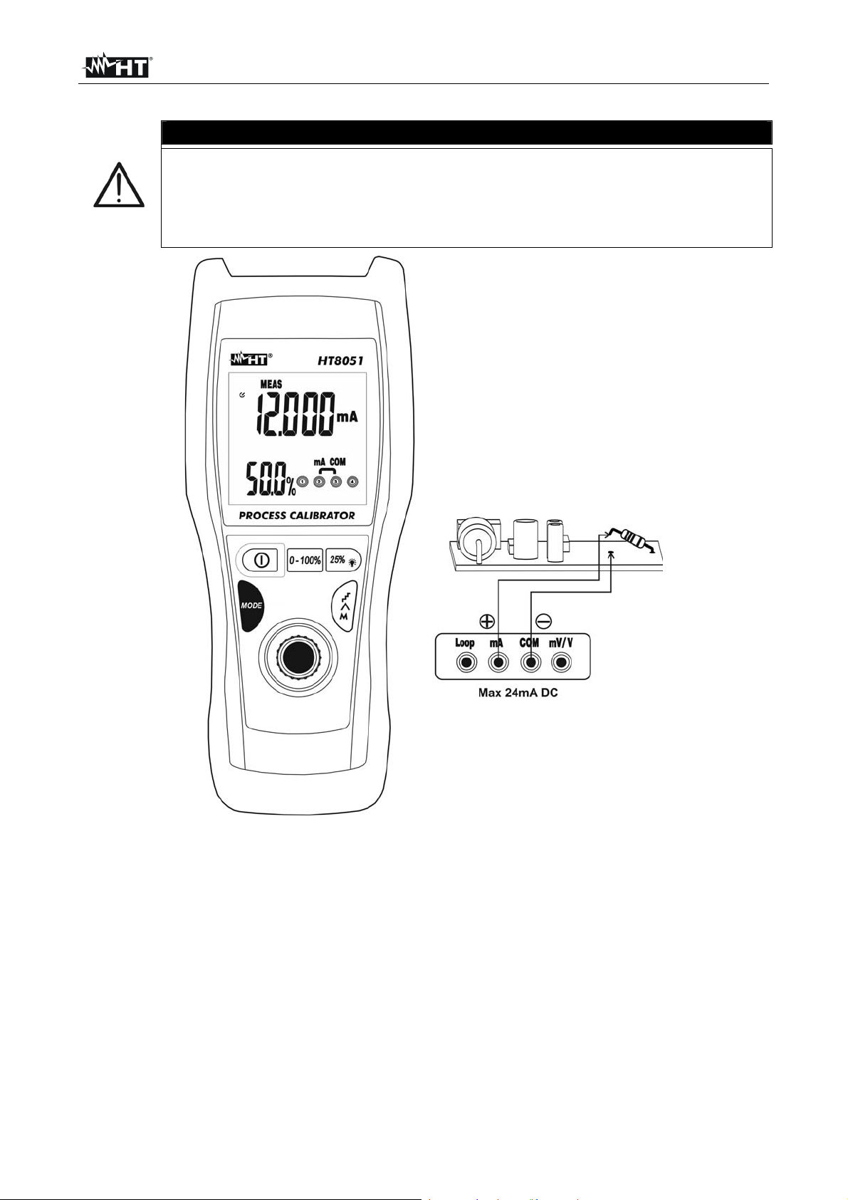
HT8051
4.3.3. DC Strommessung
Der maximale DC Eingangsstrom beträgt 24mA. Versuchen Sie nicht,
Ströme zu messen, die die Grenzwerte, die in diesem Handbuch
angegebenen werden, übersteigen. Das Überschreiten der Grenzwerte
könnte einen elektrischen Schock verursachen und das Messgerät
beschädigen.
WARNUNG
Abb. 5: DC Strommessung
1. Trennen Sie die Versorgung des zu messenden Kreises.
2. Drücken Sie die MODE Taste und wählen Sie den Messmodus MEAS mA aus. Das
Symbol “MEAS” erscheint auf dem Display.
3. Verbinden Sie die grün Messleitung mit der mA Eingangsbuchse, und die schwarze
Messleitung mit der COM Eingangsbuchse.
4. Schalten Sie die grün und die schwarze Messleitung in Reihe mit dem Kreis, dessen
Strom Sie messen möchten, und dabei achten Sie auf die Strompolarität und -richtung
(siehe Abb. 5)
5. Versorgen Sie den zu messenden Kreis. Der Stromwert wird im Hauptdisplay und der
Prozentwert in Bezug auf die Vollaussteuerung im sekundären Display angezeigt.
6. Die “-OL-”-Meldung gibt an, dass der zu messende Strom den maximalen Wert, der mit
dem Gerät gemessen werden kann, überschreitet. Das Instrument führen keine
Spannungsmessungen mit entgegengesetzter Polarität gegenüber dem Anschlußteil in
Abb. 5. Der Wert "0.000" wird im Display angezeigt.
DE - 10
Page 48

HT8051
4.3.4. Erzeugung von Gleichstrom
Der maximale erzeugte Ausgangs-Gleichstrom zur Verwendung in
passiven Kreisen beträgt 24mA
Mit eingestellter Wert 0.004mA das Display blinken intermittierend kein
Signal Generation an, wenn das Gerät nicht an ein externes Gerät
angeschlossen ist
WARNUNG
Abb. 6: Erzeugung von Gleichstrom
1. Drücken Sie die MODE Taste und wählen Sie den Messmodus SOUR mA aus. Das
Symbol “SOUR” erscheint auf dem Display
2. Stellen Sie den Messbereich des Ausgangsstroms zwischen 0-20mA und 4-20mA ein
(siehe § 4.2.7)
3. Mit dem Einstell-Schalter (siehe § 4.2.6), oder der 0-100% Taste (siehe § 4.2.2) oder
der 25%/ Taste (siehe § 4.2.3) stellen Sie den gewünschten Wert des
Ausgangsstroms ein. Der einstellbare Maximalwert beträgt 24mA. Bitte beachten Sie
folgendes: -25% = 0mA, 0% = 4mA, 100% = 20mA und 125% = 24mA. Der Stromwert
erscheint auf dem Display. Wenn nötig, drücken Sie die Taste (siehe § 4.2.5),
um Gleichstrom mit automatischer Rampe zu erzeugen
4. Verbinden Sie die grün Messleitung mit der Loop Eingangsbuc hse, und die schwarze
Messleitung mit der mV/V Eingangsbuchse
5. Stellen Sie die grün Messleitung und die schwarze Messleitung in die Punkte mit
positivem und negativem Potenzial des externen Gerätes, das versorgt werden muss
(siehe Abb. 6)
6. Zur Erzeugung des negativen Stromwerts drehen Sie die Messleitungen in die
umgekehrte Richtung in Bezug auf die Verbindung in Abb. 6
DE - 11
Page 49

HT8051
4.3.5. Messung von Ausgangs-Gleichstrom aus externen Wandlern (Loop)
WARNUNG
In diesem Betrieb liefert das Gerät eine stabile Ausgangsspannung von
25VDC±10%, die in der Lage ist, einen externen Wandler zu versorgen
und die gleichzeitige Messung des Stroms zu ermöglichen.
Der maximale Ausgangsstrom ist Gleichstrom 24mA. Versuchen Sie nicht,
Ströme zu messen, die die Grenzwerte, die in diesem Handbuch
angegebenen werden, übersteigen. Das Überschreiten der Grenzwerte
könnte einen elektrischen Schock verursachen und das Messgerät
beschädigen.
Abb. 7: Messung von Ausgangs-Gleichstrom aus externen Wandlern (Loop)
1. Trennen Sie die Versorgung des zu messenden Kreises.
2. Drücken Sie die MODE Taste und wählen Sie den Messmodus MEAS LOOP mA aus.
Die Symbole “MEAS” und “LOOP” erscheinen auf der Anzeige.
3. Verbinden Sie die grün Messleitung mit der Loop Eingangsbuchse, und die schwarze
Messleitung mit der mA Eingangsbuchse.
4. Verbinden Sie die grün und die schwarze Messleitung mit dem externen Wandler, und
dabei achten Sie auf die Strompolarität und -richtung (siehe Abb. 7)
5. Versorgen Sie den zu messenden Kreis. Der Stromwert erscheint auf dem Display.
6. Die “-OL-”-Meldung gibt an, dass der zu messende Strom den maximalen Wert, der mit
dem Gerät gemessen werden kann, überschreitet. Zur Erzeugung des negativen
Spannungswerts drehen Sie die Messleitungen in die umgekehrte Richtung in Bezug
auf die Verbindung in Abb. 7
DE - 12
Page 50

HT8051
4.3.6. Simulation eines Wandlers
In diesem Betrieb liefert das Gerät einen einstellbaren Ausgangsstrom bis
24mADC. Es ist notwendig, eine externe Versorgung mit Spannung
zwischen 12V und 28VDC zu liefern, um den Strom einstellen zu können
Mit eingestellter Wert 0.004mA das Display blinken intermittierend kein
Signal Generation an, wenn das Gerät nicht an ein externes Gerät
angeschlossen ist
WARNUNG
Abb. 8: Simulation eines Wandlers
1. Drücken Sie die MODE Taste und wählen Sie den Messmodus SIMU mA aus. Die
Symbole “OUT” und “SOUR” erscheinen auf der Anzeige.
2. Stellen Sie den Messbereich des Stroms zwischen 0-20mA und 4-20mA ein (siehe §
4.2.7.
3. Mit dem Einstell-Schalter (siehe § 4.2.6) oder der 0-100% Taste (siehe § 4.2.2), oder
der 25%/ Taste (siehe § 4.2.3) stellen Sie den gewünschten Wert des
Ausgangsstroms ein. Der einstellbare Maximalwert beträgt 24mA. Bitte beachten Sie
folgendes: -25% = 0mA, 0% = 4mA, 100% = 20mA und 125% = 24mA. Der Stromwert
erscheint auf dem Display. Wenn nötig, drücken Sie die Taste (siehe § 4.2.5),
um Gleichstrom mit automatischer Rampe zu erzeugen.
4. Verbinden Sie die grün Messleit ung mit der mV/V Eingangsbuchse, und die schwarze
Messleitung mit der COM Eingangsbuchse.
5. Stellen Sie die grün Messleitung und die schwarze Messleitung in die Punkte mit
positivem Potenzial der externen Quelle und positivem Potenzial des externen
Messgerätes (z.B.: Multimeter – siehe Abb. 8)
6. Zur Erzeugung des negativen Stromwerts drehen Sie die Messleitungen in die
umgekehrte Richtung in Bezug auf die Verbindung in Abb. 8
DE - 13
Page 51

HT8051
5. WARTUNG UND PFLEGE
5.1. ALLGEMEINE INFORMATIONEN
1. Das Gerät, das Sie gekauft haben, ist ein Präzisionsinstrument. Überschreiten Sie
niemals die technischen Grenzwerte in dieser Bedienungsanleitung bei der Messung
oder bei der Lagerung, um mögliche Beschädigungen oder Gefahren zu vermeiden.
2. Benutzen Sie das Gerät nicht in Umgebungen mit hohem Luftfeuchtigkeitspegel oder
hohen Temperaturen. Setzen Sie es nicht direktem Sonnenlicht aus.
3. Schalten Sie das Gerät nach Gebrauch wieder aus. Falls das Gerät für eine längere
Zeit nicht benutzt werden wird, entfernen Sie die Batterie, um Flüssigkeitslecks zu
vermeiden, die die innere Schaltkreise des Gerätes beschädigen könnten.
5.2. AUFLADEN DER INTERNEN BATTERIE
Wenn im Display das Symbol “ ” erscheint, muss die interne Batterie gewechselt werden.
Nur Fachleute oder ausgebildete Techniker dürfen dieses WartungsVerfahren durchführen.
1. Schalten Sie das Gerät mit der Taste aus.
2. Das Batterieladegerät am Stromnetz 230V/50Hz anschließen
3. Verbinden Sie die rote Messleitung mit der Loop-Buchse, und die schwarze
Messleitung mit der COM-Buchse. Das Gerät einschalten der Hintergrundbeleuchtung
in festen Modus und der Ladevorgang beginnt
4. Der Ladevorgang ist beendet, wenn die Hintergrundbeleuchtung im Display blinkt.
Dieser Vorgang hat eine Dauer von ca.. 4 Stunden
5. Trennen Sie das Ladegerät am Ende der Operation
Die Li-ION Batterie muss bei jeder Verwendung des Gerätes völlig
aufgeladen werden, damit ihre Dauer nicht eingeschränkt wird. Das Gerät
kann eventuell auch mit 1x9V alkalischer Batterie Typ NEDA1604 006P
IEC6F22. Verbinden Sie das Batterieladegerät mit der Gerät nicht,
wenn es mit einer alkalischen Batterie versorgt wird.
Sollten Sie beim Aufladen eine Überheizung vom Gerät oder von
Geräteteilen feststellen, trennen Sie sofort das Gerät vom Stromnetz ab
Wenn die Batteriespannung zu niedrig ist (<5V), kann die
Hintergrundbeleuchtung nicht einschalten. Noch weiterhin den Prozess in
der gleichen Weise
5.3. REINIGUNG
Zum Reinigen des Gerätes kann ein weiches trockenes Tuch verwendet werden.
Benutzen Sie keine feuchten Tücher, Lösungsmittel oder Wasser, usw.
5.4. LEBENSENDE
WARNUNG: Das Symbol auf dem Gerät zeigt, dass die Gerätschaft und seine
Zubehörteile und die Batterie getrennt gesammelt und korrekt entsorgt werden
müssen.
WARNUNG
WARNUNG
DE - 14
Page 52

HT8051
6. TECHNISCHE DATEN
6.1. TECHNISCHE EIGENSCHAFTEN
Die Messgenauigkeit ist angegeben als [%Abl. + (Ziff*Aufl.)] bei 18°C 28°C, <75%RH
Gemessene DC Spannung
Bereich Auflösung Genauigkeit Eingangswiderstand Überlastschutz
0.01100.00mV
0.00110.000V
Erzeugte DC Spannung
Bereich Auflösung Genauigkeit Überlastschutz
0.01100.00mV
0.00110.000V
Gemessener DC Strom
Bereich Auflösung Genauigkeit Überlastschutz
0.00124.000mA
Sampling Widerstand: 10
Gemessener DC Strom mit Loop-funktionen
Bereich Auflösung Genauigkeit Überlastschutz
0.00124.000mA
Sampling Widerstand: 10
Erzeugter DC Strom (SOUR und SIMU-funktionen)
Bereich Auflösung Genauigkeit Prozentwerte Überlastschutz
0.00124.000mA
-25.00 125.00%
Betriebsmodus SOUR mA maximal zulässige Belastung 1k @ 20mA
Betriebsmodus SIMU mA Schleifenspannung: 24V Nennwert, 28V Maximalwert, 12V Mindestwert
SIMU Modus Bezugsgrößen
Loop Spannung Erzeugter DC Strom Last Widerstand
12V 11mA
14V 13mA
16V 15mA
18V 17mA
20V 19mA
22V 21mA
24V 23mA
25V 24mA
Loop-Betriebsmodus (Stromschleife)
Bereich Auflösung Überlastschutz
25VDC ±10% Nicht angegeben 30VDC
0.01mV
0.001V
0.01mV
0.001V
0.001mA
0.001mA
0.001mA
0.01%
(0.02Abl.+4Ziffern) 1M
(0.02Abl.+4Ziffern)
(0.02%Abl.+ 4Ziffern)
mit 100mA integrierter Sicherung
(0.02%Abl.+ 4Ziffern)
0% = 4mA
(0.02%Abl.+ 4Ziffern)
100% = 20mA
125% = 24mA
30VDC
30VDC
max 50mADC
max 30mADC
max 30mADC
0.8k
DE - 15
Page 53

HT8051
6.2. ALLGEMEINE EIGENSCHAFTEN
6.2.1. Bezugsnormen
Sicherheit: IEC/EN 61010-1
Isolation: Doppelte Isolation
Verschmutzungsgrad: 2
Messkategorie: CAT I 30V
Maximale Betriebshöhe: 2000m
6.2.2. Allgemeine Eigenschaften
Mechanische Eigenschaften
Abmessungen (L x B x H): 195 x 92 x 55mm
Gewicht (inklusive Batterie): 400g
Display
Eigenschaften: 5-stelliges LCD + Dezimalzeichen und -punkt
Überlastanzeige: Das Symbol “-OL-” erscheint auf dem Display
Stromversorgung
Wiederaufladbare Batterie: 1x7.4/8.4V 600mAh Li-ION
Alkalische Batterie: 1x9V Typ NEDA1604 006P IEC6F22
Externer Adapter 230VAC/50Hz – 12VDC/1A
Lebensdauer: Modus SOUR: ca. 8 Stunden (@ 12mA, 500)
Modus MEAS/SIMU: ca. 15 Stunden
Batteriewarnanzeige: Das Symbol “ ” erscheint auf der Anzeige
Auto Power Off: Nach 20 Minuten (einstellbar) Nichtgebrauch
6.3. UMWELTBEDINGUNGEN
6.3.1. Klimabedingungen für den Gebrauch
Bezugstemperatur: 18°C 28°C
Betriebstemperatur: -10 ÷ 40°C
Zulässige Betriebs-Luftfeuchtigkeit: <95%RH bis 30°C, <75%RH bis 40°C
<45%RH bis 50°C, <35%RH bis 55°C
Lagerungstemperatur: -20 ÷ 60°C
Dieses Gerät ist konform im Sinne der Niederspannungsrichtlinie 2006/95/EWG,
(LVD) und der EMV Richtlinie 2004/108/EWG
6.4. ZUBEHÖR
6.4.1. Mitgeliefertes Zubehör
Zwei Messleitungen
Zwei Krokodilklemmen
Schutzschale
Wiederaufladbare Batterie (nicht eingelegt)
Externes Batterieladegerät
Benutzerhandbuch
Hartschalenkoffer
DE - 16
Page 54

HT8051
7. SERVICE
7.1. GARANTIEBEDINGUNGEN
Für dieses Gerät gewähren wir Garantie auf Material- oder Produktionsfehler,
entsprechend unseren allgemeinen Geschäftsbedingungen. Während der Garantiefrist
behält sich der Hersteller das Recht vor, das Produkt wahlweise zu reparieren oder zu
ersetzen. Falls Sie das Gerät aus irgendeinem Grund für Reparatur oder Austausch
einschicken müssen, setzen Sie sich bitte zuerst mit dem lokalen Händler in Verbindung,
bei dem Sie das Gerät gekauft haben. Transportkosten werden vom Kunden getragen.
Vergessen Sie nicht, einen Bericht über die Gründe für das Einschicken beizulegen
(erkannte Mängel). Verwenden Sie nur die Originalverpackung. Alle Schäden beim
Versand, die auf Nichtverwendung der Originalverpackung zurückzuführen sind, hat auf
jeden Fall der Kunde zu tragen.
Der Hersteller übernimmt keine Haftung für Personen- oder Sachschäden.
Von der Garantie ausgenommen sind:
Reparatur und/oder Ersatz von Zubehör und Batterie (nicht durch die Garantie
gedeckt)
Reparaturen, die aufgrund unsachgemäßer Verwendung oder durch unsachgemäße
Kombination mit inkompatiblen Zubehörteilen oder Geräten erforderlich werden.
Reparaturen, die aufgrund von Beschädigungen durch ungeeignete
Transportverpackung erforderlich werden.
Reparaturen, die aufgrund von vorhergegangenen Reparaturversuchen durch
ungeschulte oder nicht autorisierte Personen erforderlich werden.
Geräte, die modifiziert wurden, ohne dass das ausdrückliche Einverständnis des
Herstellers dafür vorlag.
Gebrauch, der den Eigenschaften des Gerätes und den Bedienungsanleitungen nicht
entspricht.
Der Inhalt dieser Bedienungsanleitung darf ohne das Einverständnis des Herstellers in
keiner Form reproduziert werden
Unsere Produkte sind patentiert und unsere Warenzeichen eingetragen. Wir
behalten uns das Recht vor, Spezifikationen und Preise aufgrund eventuell
notwendiger technischer Verbesserungen oder Entwicklungen zu ändern.
7.2. SERVICE
Für den Fall, dass das Gerät nicht korrekt funktioniert, stellen Sie vor der
Kontaktaufnahme mit Ihrem Händler sicher, dass die Batterie und die Kabel korrekt
eingesetzt sind und funktionieren, und sie ersetzen, wenn nötig.
Stellen Sie sicher, dass Ihre Betriebsabläufe der in dieser Betriebsanleitung
beschriebenen Vorgehensweise entsprechen. Falls Sie das Gerät aus irgendeinem Grund
für Reparatur oder Austausch einschicken müssen, setzen Sie sich bitte zuerst mit dem
lokalen Händler in Verbindung, bei dem Sie das Gerät gekauft haben. Transportkosten
werden vom Kunden getragen. Vergessen Sie nicht, einen Bericht über die Gründe für das
Einschicken beizulegen (erkannte Mängel). Verwenden Sie nur die Originalverpackung.
Alle Schäden beim Versand, die auf Nichtverwendung der Originalverpackung
zurückzuführen sind, hat auf jeden Fall der Kunde zu tragen.
DE - 17
Page 55

FRANÇAIS
Manuel d’utilisation
Copyright HT ITALIA 2012 Version FR 1.00 - 17/12/2012
Page 56

HT8051
Table des matières :
1. PRECAUTIONS ET MESURES DE SECURITE .......................................................... 2
1.1. Instructions préliminaires ....................................................................................... 2
1.2. Pendant l’utilisation ................................................................................................ 3
1.3. Après l’utilisation .................................................................................................... 3
1.4. Définition de catégorie de mesure (surtension) ..................................................... 3
2. DESCRIPTION GENERALE ......................................................................................... 4
3. PREPARATION A L'UTILISATION ............................................................................... 4
3.1. Vérification initiale .................................................................................................. 4
3.2. Alimentation de l’instrument .................................................................................. 4
3.3. Calibration ............................................................................................................. 4
3.4. Conservation ......................................................................................................... 4
4. MODE D'UTILISATION ................................................................................................ 5
4.1. Description de l’instrument .................................................................................... 5
4.2. Description des touches de fonction et réglages initiaux ....................................... 6
4.2.1. Touche
4.2.2. Touche 0-100% ............................................................................................................ 6
4.2.3. Touche 25%/
4.2.4. Touche MODE ............................................................................................................. 6
4.2.5. Touche
4.2.6. Sélecteur de réglage .................................................................................................... 7
4.2.7. Réglage des échelles de mesure pour le courant à la sortie ....................................... 7
4.2.8. Réglage et invalidation de la fonction Auto Power OFF ............................................... 7
.................................................................................................................... 6
............................................................................................................ 6
............................................................................................................. 7
4.3. Description des fonctions de mesure ..................................................................... 8
4.3.1. Mesure de Tension DC ................................................................................................ 8
4.3.2. Génération de Tension DC .......................................................................................... 9
4.3.3. Mesure de Courant DC .............................................................................................. 10
4.3.4. Génération de Courant DC ........................................................................................ 11
4.3.5. Mesure de courant DC à la sortie des transducteurs externes (Loop) ....................... 12
4.3.6. Simulation d'un transducteur ...................................................................................... 13
5. ENTRETIEN ............................................................................................................... 14
5.1. Aspects généraux ................................................................................................ 14
5.2. Recharge de la batterie interne ........................................................................... 14
5.3. Nettoyage de l’instrument .................................................................................... 14
5.4. Fin de la durée de vie .......................................................................................... 14
6. SPECIFICATIONS TECHNIQUES ............................................................................. 15
6.1. Caractéristiques techniques ................................................................................ 15
6.2. Caractéristiques générales .................................................................................. 16
6.2.1. Normes de référence ................................................................................................. 16
6.2.2. Caractéristiques générales ........................................................................................ 16
6.3. Environnement .................................................................................................... 16
6.3.1. Conditions environnementales d'utilisation ................................................................ 16
6.4. Accessoires ......................................................................................................... 16
6.4.1. Accessoires fournis .................................................................................................... 16
7. ASSISTANCE ............................................................................................................. 17
7.1. Conditions de garantie ......................................................................................... 17
7.2. Assistance ........................................................................................................... 17
FR - 1
Page 57

HT8051
1. PRECAUTIONS ET MESURES DE SECURITE
Cet instrument a été conçu conformément à la directive CEI/EN61010-1, relative aux
instruments de mesure électroniques. Pour votre propre sécurité et afin d’éviter tout
endommagement de l’instrument, veuillez suivre avec précaution les instructions décrites
dans ce manuel et lire attentivement toutes les remarques précédées du symbole .
Avant et pendant l’exécution des mesures, veuillez respecter scrupuleusement ces
indications :
Ne pas effectuer de mesures dans des endroits humides.
Eviter d’utiliser l’instrument en la présence de gaz ou matériaux explosifs, de
combustibles ou dans des endroits poussiéreux.
Se tenir éloigné du circuit sous test si aucune mesure n’est en cours d’exécution.
Ne pas toucher de parties métalliques exposées telles que des bornes de mesure
inutilisées, etc.
Ne pas effectuer de mesures si vous détectez des anomalies sur l’instrument telles
qu’une déformation, des fuites de substances, une absence d’affichage de l’écran, etc.
Ne jamais appliquer une tension supérieure à 30V entre chaque couple d'entrées
ou bien entre toute entrée et la référence de terre afin d'éviter de possibles chocs
électriques et/ou dommages à l'instrument.
Dans ce manuel, et sur l’instrument, on utilisera les symboles suivants :
Attention : s’en tenir aux instructions reportées dans c e manuel ; une utilisation
inappropriée pourrait endommager l’instrument ou ses composants.
Instrument à double isolement.
Référence de terre.
1.1. INSTRUCTIONS PRELIMINAIRES
Cet instrument a été conçu pour une utilisation dans un env ironnement avec niveau de
pollution 2.
Il peut être utilisé pour des mesures de TENSION DC et de COURANT DC.
Veuillez suivre les normes de sécurité principales visant à protéger l'utilisateur contre
des courants dangereux et l’instrument contre une utilisation erronée.
Seuls les embouts et les accessoires fournis avec l’instrument garantissent la
conformité avec les normes de sécurité. Ils doivent être en bon état et, si nécessaire,
remplacés à l’identique.
Ne pas mesurer de circuits dépassant les limites de tension spécifiées.
Ne pas exécuter de mesures dans des conditions environnementales autres que celles
indiquées à la § 6.2.1.
Vérifier que la batterie est insérée correctement.
Avant de connecter les embouts au circuit sous test, vérifier que la mesure fonctionne
correctement afin d'éviter d'endommager l'instrument.
FR - 2
Page 58
HT8051
1.2. PENDANT L’UTILISATION
Veuillez lire attentivement les recommandations et instructions suivantes :
ATTENTION
Le non-respect des avertissements et/ou instructions pourrait endommager
l’instrument et/ou ses composants ou mettre en danger l’utilisateur.
Avant de sélectionner une fonction de mesure, déconnecter les embouts de mesure du
circuit sous test.
Lorsque l’instrument est connecté au circuit sous test, ne jamais toucher les bornes
inutilisées.
Pendant les connexions, brancher la borne « COM » avant la borne « Positive ». Lors
de la procédure opposée, débrancher la borne « Positive » avant la borne « COM ».
Ne pas ap pliquer une tension supérieure à 30V entre les entrées de l'instrument
afin d'éviter d'endommager l'instrument.
1.3. APRES L’UTILISATION
Une fois les mesures terminées, éteindre l'instrument en appuyant sur la touche
.
Si l’instrument n’est pas utilisé pendant longtemps, retirer la batterie.
1.4. DEFINITION DE CATEGORIE DE MESURE (SURTENSION)
La norme IEC/EN61010-1 : Prescriptions de sécurité pour les instruments électriques de
mesure, le contrôle et l’utilisation en laboratoire, Partie 1 : Prescriptions générales, définit
ce qu’on entend par catégorie de mesure, généralement appelée catégorie de surtension.
A la § 6.7.4 : Circuits de mesure, on lit :
(OMISSIS)
Les circuits sont divisés dans les catégories de mesure qui suivent :
La catégorie de mesure IV sert pour les mesures exécutées sur une source
d'installation à faible tension.
Par exemple, les appareils électriques et les mesures sur des dispositifs primaires à
protection contre surtension et les unités de contrôle d’ondulation.
La catégorie de mesure III sert pour les mesures exécutées sur des installations dans
les bâtiments.
Par exemple, les mesures sur des panneaux de distribution, des disjoncteurs, des
câblages, y compris les câbles, les barres, les boîtes de jonction, les interrupteurs, les
prises d’installation fixe et le matériel destiné à l’emploi industriel et d’autres
instruments tels que par exemple les moteurs fixes avec connexion à une installation
fixe.
La catégorie de mesure II sert pour les mesures exécutées sur les circuits connectés
directement à l'installation à faible tension.
Par exemple, les mesures effectuées sur les appareils électroménagers, les outils
portatifs et sur des appareils similaires.
La catégorie de mesure I sert pour les mesures exécutées sur des circuits n’étant pas
directement connectés au RESEAU DE DISTRIBUTION.
Par exemple, les mesures sur des circuits ne dérivant pas du RESEAU et des circuits
dérivés du RESEAU spécialement protégés (interne). Dans le dernier cas mentionné,
les tensions transitoires sont variables ; pour cette raison, (OMISSIS) on demande que
l’utilisateur connaisse la capacité de résistance transitoire de l’appareil.
FR - 3
Page 59

HT8051
2. DESCRIPTION GENERALE
L'instrument HT8051 présente les caractéristiques qui suivent :
Mesure de tension jusqu'à 10V DC
Mesure de courant jusqu'à 24mA DC
Génération de tension avec amplitude jusqu'à 100mV DC et 10V DC
Génération de courant avec amplitude jusqu'à 24mA DC avec affichage en mA et %
Génération courant et tension avec sorties en rampe pouvant être sélectionnées
Mesure de courant à la sortie des transducteurs (Loop)
Simulation d'un transducteur externe
Sur la partie frontale on trouve quelques touches de fonction (voir la § 4.2) pour la
sélection du type d'opération. La grandeur sélectionnée s'affiche à l'écran avec l'indication
de l'unité de mesure et des fonctions validées.
3. PREPARATION A L'UTILISATION
3.1. VERIFICATION INITIALE
L’instrument a fait l’objet d’un contrôle mécanique et électrique avant d’être expédié.
Toutes les précautions possibles ont été prises pour garantir une livraison de l’instrument
en bon état.
Toutefois, il est recommandé d’effectuer un contrôle rapide de l'instrument afin de détecter
des dommages qui auraient pu avoir lieu pendant le transport. En cas d’anomalies,
n’hésitez pas à contacter votre commissionnaire de transport.
S’assurer que l’emballage contient tous les accessoires listés à la § 6.4. Dans le cas
contraire, contacter le revendeur.
S’il était nécessaire de renvoyer l’instrument, veuillez respecter les instructions dont à la §
7.
3.2. ALIMENTATION DE L’INSTRUMENT
L'instrument est alimenté par une batterie rechargeable de 7.4V Li-ION incluse dans
l'emballage. Lorsque la batterie est déchargée, le symbole «
la batterie à l'aide du chargeur fourni de dotation, consulter la § 5.2.
3.3. CALIBRATION
L’instrument est conforme aux spécifications techniques décrites dans ce manuel. Ses
performances sont garanties pendant 12 mois.
3.4. CONSERVATION
Afin d’assurer la précision des mesures, après une longue période de stockage en
conditions environnementales extrêmes, il est conseillé d’attendre le temps nécessaire
pour que l’instrument revienne aux conditions normales (voir § 6.2.1).
» s'affiche. Pour recharger
FR - 4
Page 60

HT8051
4. MODE D'UTILISATION
4.1. DESCRIPTION DE L’INSTRUMENT
LEGENDE :
1. Entrées Loop, mA, COM,
mV/V
2. Afficheur LCD
3. Touche
4. Touche 1-100%
5. Touche 25%/
6. Touche MODE
7. Touche
8. Sélecteur de réglage
Fig. 1 : Description de l’instrument
LEGENDE :
1. Indicateurs modes de fonction
2. Symbole d'Auto Power OFF
3. Indication de batterie déchargée
4. Indications unités de mesure
5. Afficheur principal
6. Indicateurs fonctions Rampe
7. Indicateurs de niveau du signal
8. Afficheur secondaire
9. Indicateurs des entrées utilisées
Fig. 2 : Description de l'afficheur
FR - 5
Page 61

HT8051
4.2. DESCRIPTION DES TOUCHES DE FONCTION ET REGLAGES INITIAUX
4.2.1. Touche
En appuyant sur cette touche on peut allumer/éteindre l'instrument. La référence de la
dernière fonction sélectionnée est affichée à l'écran.
4.2.2. Touche 0-100%
Dans les modes de fonctionnement SOUR mA (voir la § 4.3.4), SIMU mA (voir la § 4.3.6),
OUT V et OUT mV (voir § 4.3.2) la pression de cette touche permet de régler rapidement
la valeur initiale (0mA ou 4mA) et la valeur finale (20mA) du courant généré à la sortie, la
valeur initiale (0.00mV) et finale (100.00mV) et la valeur initiale (0.000V) et finale
(10.000V) du tension généré à la sortie. Les valeurs en pourcentage « 0% » et « 100% »
sont montrées dans l'afficheur secondaire. La valeur affichée peut toujours être modifiée à
l'aide du sélecteur de réglage (voir la § 4.2.6). Les indications « 0% » et « 100% » est
affiché sur l’écran
ATTENTION
L'instrument NE peut PAS être utilisé pour la gestion simultanée des
opérations de mesure (MEASURE) et génération des signaux
(SOURCE).
4.2.3. Touche 25%/
Dans les modes de fonctionnement SOUR mA (voir la § 4.3.4) et SIMU mA (voir la §
4.3.6), OUT V et OUT mV (voir la § 4.3.2), la pression de cette touche permet
d'augmenter/diminuer rapidement la valeur du courant/tension générés à la sortie par pas
de 25% (0%, 25%, 50%, 75%, 100%) de l'échelle de mesure sélectionnée. Notamment,
les valeurs suivantes sont disponibles :
Echelle 0 20mA 0.000mA, 5.000mA, 10.000mA, 15.000mA, 20.000mA
Echelle 4 20mA 4.000mA, 8.000mA, 12.000mA, 16.000mA, 20.000mA
Echelle 0 10V 0.000V, 2.500V, 5.000V, 7.500V, 10.000V
Echelle 0 100mV 0.00mV, 25.00mV, 50.00mV, 75.00mV, 100.00mV
Les valeurs en pourcentage sont montrées à l'afficheur secondaire et la valeur à l'écran
peut toujours être modifiée à l'aide du sélecteur de réglage (voir la § 4.3.6). L’indications
« 25% » est affiché sur l’écran.
Garder la touche 25%/ enfoncée pendant 3 secondes pour activer le rétro éclairage de
l'écran. La fonction se désactive automatiquement après environ 20 secondes
4.2.4. Touche MODE
La pression en séquence de cette touche permet de sélectionner les modes de
fonctionnement disponibles sur l'instrument. Notamment, les options suivantes sont
possibles :
OUT SOUR mA génération du courant à la sortie jusqu'à 24mA (voir la § 4.3.4)
OUT SIMU mA simulation d'un transducteur dans un anneau de courant avec
alimentation auxiliaire (voir la § 4.3.6)
OUT V génération de tension DC à la sortie jusqu'à 10V (voir la § 4.3.2)
OUT mV génération de tension DC à la sortie jusqu'à 100mV DC (voir la § 4.3.2)
MEAS V mesure de tension DC (max 10V) (voir la § 4.3.1)
MEAS mV mesure de tension DC (max 100mV) (voir la § 4.3.1)
MEAS mA mesure de courant DC (max 24mA) (voir la § 4.3.3)
MEAS LOOP mA mesure de courant DC à la sortie des transducteurs externes
(voir la § 4.3.5)
FR - 6
Page 62

HT8051
4.2.5. Touche
Dans les modes de fonctionnement SOUR mA, SIMU mA, OUT V et OUT mV, la pression
de cette touche permet de régler le courant/tension à la sortie avec rampe automatique,
pour les échelles de mesure 0 20mA ou 4 20mA et 0 100mV o 0 10V pour le
tension. Les rampes disponibles sont montrées dans le Tableau 1 ci-dessous.
Type de rampe Description Action
Tableau 1 : Liste des rampes disponibles pour le courant à la sortie
Rampe lente linéaire Passage de 0% 100% 0% en 40s
Rampe rapide linéaire Passage de 0% 100% 0% en 15s
Rampe avec marche
Passage de 0% 100% 0% par pas de
25% avec rampes de 5s
Appuyer sur une touche quelconque ou éteindre et rallumer l'instrument pour quitter cette
fonction.
4.2.6. Sélecteur de réglage
Dans les modes de fonctionnement SOUR mA, SIMU mA, OUT V et OUT mV, le
sélecteur de réglage (voir la Fig. 1 – Position 8) permet d'exécuter une programmation
pointue du courant/tension à la sortie générés avec des résolutions de 1A
(0.001V/0.01mV) / 10A (0.01V/0.1mV) / 100A (0.1V/1mV). Pour la relative utilisation,
suivre cette procédure :
1. Sélectionner les modes de fonctionnement SOUR mA, SIMU mA, OUT V ou OUT mV.
2. En cas de génération de courant, sélectionner l'une des échelles de mesure 0 20mA
ou 4 20mA (voir la § 4.2.7).
3. Appuyer sur le sélecteur de réglage en insérant la résolution souhaitée. Le symbole
flèche « » se déplace à la position souhaitée sur les chiffres de l'afficheur principal
après le point décimal. La résolution par défaut est de 1A (0.001V/0.01Mv)
4. Tourner le sélecteur de réglage en insérant la valeur souhaitée de courant/tension à la
sortie. La valeur correspondante en pourcentage est montrée dans l'afficheur
secondaire.
4.2.7. Réglage des échelles de mesure pour le courant à la sortie
Dans les modes de fonctionnement SOUR mA et SIMU mA, il est possible de régler
l'échelle de sortie du courant généré. Suivre cette procédure :
1. Eteindre l'instrument par la touche “ ”
2. Allumer l'instrument en appuyant sur la touche
0-100%
3. La valeur "0.000mA» ou «4.000mA" s'affiche pendant environ 3 secondes avant de
revenir à la vue normale
4.2.8. Réglage et invalidation de la fonction Auto Power OFF
L'instrument dispose d'une fonction d'Arrêt auto (Auto Power OFF) qui s'active au bout
d'un certain délai d'inactivité pour ne pas décharger la batterie interne. Le symbole « »
est montré à l'écran avec la fonction validée et la valeur par défaut est de 20 minutes.
Pour le réglage de ce délai ou pour désactiver la fonction, suivre cette procédure :
1. A l'aide de la touche « », allumer l'instrument en gardant la touche MODE enfoncée.
Le message « PS – XX » est montré à l'écran pendant 5s ; « XX » indique le temps en
minutes.
2. Tourner le sélecteur de réglage pour introduire la valeur temporelle dans l'intervalle de
5 30minutes ou bien sélectionner la valeur « OFF » pour désactiver cette fonction.
3. Attendre pendant 5s pour que l'instrument sorte automatiquement de la fonction.
FR - 7
Page 63

HT8051
4.3. DESCRIPTION DES FONCTIONS DE MESURE
4.3.1. Mesure de Tension DC
ATTENTION
La tension maximale DC pouvant être appliquée aux entrées est de 30V
DC. Ne pas mesurer de tensions excédant les limites indiquées dans ce
manuel. Le dépassement de ces limites pourrait entraîner des chocs
électriques pour l'utilisateur et endommager l’instrument.
Fig. 3 : Mesure de Tension DC
1. Appuyer sur la touche MODE et sélectionner les modes de mesure MEAS V ou MEAS
mV. Le symbole « MEAS » s'affiche à l'écran.
2. Insérer le câble vert dans l’entrée mV/V et le câble noir dans l'entrée COM.
3. Positionner l'embout vert et l'embout noir respectivement dans les points à potentiel
positif et négatif du circuit sous test (voir la Fig. 3). La valeur de tension est montrée
dans l'afficheur principal et la valeur en pourcentage par rapport à la fin d'échelle dans
l'afficheur secondaire.
4. Le message « -OL- » indique que la tension sous test dépasse la valeur maximale
mesurable par l'instrument. L'instrument ne pas effectuer des mesures de tension de
polarité opposée par rapport à la connexion de la Fig. 3. La valeur "0.000" est affiché
sur l'écran
FR - 8
Page 64

HT8051
4.3.2. Génération de Tension DC
La tension maximale DC pouvant être appliquée aux entrées est de 30V
DC. Ne pas mesurer de tensions excédant les limites indiquées dans ce
manuel. Le dépassement de ces limites pourrait entraîner des chocs
électriques pour l'utilisateur et endommager l’instrument.
ATTENTION
Fig. 4 : Génération de Tension DC
1. Appuyer sur la touche MODE et sélectionner les modes OUT V ou OUT mV. Le
symbole « OUT » s'affiche à l'écran.
2. Utiliser le sélecteur de réglage (voir la § 4.2.6) ou la touche 0-100% (voir § 4.2.2), ou la
touche 25%/
(voir la § 4.2.3) pour insérer la valeur souhaitée de tension à la sortie.
Les valeurs maximales pouvant être réglées sont de 100mV (OUT mV) et 10V (OUT
V). La valeur de tension apparaît à l’écran.
3. Insérer le câble vert dans l’entrée mV/V et le câble noir dans l'entrée COM.
4. Positionner l'embout vert et l'embout noir respectivement dans les points à potentiel
positif et négatif du dispositif externe (voir la Fig. 4).
5. Pour la génération de la valeur négative de tension, tourner les embouts de mesure
dans le sens inverse par rapport à la connexion de Fig. 4.
FR - 9
Page 65

HT8051
4.3.3. Mesure de Courant DC
Le courant d’entrée maximum DC est de 24mA. Ne pas mesurer de
courants excédant les limites indiquées dans ce manuel. Le dépassement
de ces limites pourrait entraîner des chocs électriques pour l'utilisateur et
endommager l’instrument.
ATTENTION
Fig. 5 : Mesure de Courant DC
1. Couper l'alimentation au circuit sous test.
2. Appuyer sur la touche MODE et sélectionner le mode de mesure MEAS mA. Le
symbole « MEAS » s'affiche à l'écran.
3. Insérer le câble vert dans l’entrée mA et le câble noir dans l'entrée COM.
4. Connecter l'embout vert et l'embout noir en série au circuit duquel on veut mesurer le
courant en respectant la polarité et la direction du courant (voir la Fig. 5).
5. Alimenter le circuit sous test. La valeur de courant est montrée dans l'afficheur principal
et la valeur en pourcentage par rapport à la fin d'échelle dans l'afficheur secondaire.
6. Le message « -OL- » indique que le courant sous test dépasse la valeur maximale
mesurable par l'instrument. L'instrument ne pas effectuer des mesures de tension de
polarité opposée par rapport à la connexion de la Fig. 5. La valeur "0.000" est affiché
sur l'écran.
FR - 10
Page 66

HT8051
4.3.4. Génération de Courant DC
Le courant DC maximum généré à la sortie pour l'utilisation sur circuits
passifs est de 24mA
Avec valeur définie 0.004mA l'affichage clignote par intermittence pour
indiquer qu'aucune génération du signal de l'instrument n'est pas
connecté à l'appareil externe
ATTENTION
Fig. 6 : Génération de Courant DC
1. Appuyer sur la touche MODE et sélectionner le mode de mesure SOUR mA. Le
symbole « SOUR » s'affiche à l'écran.
2. Définir l'échelle de mesure du courant à la sortie entre 0-20mA et 4-20mA (voir la §
4.2.7).
3. Utiliser le sélecteur de réglage (voir la § 4.2.6) ou la touche 0-100% (voir § 4.2.2), ou la
touche 25%/ (voir la § 4.2.3) pour insérer la valeur souhaitée du courant à la sortie.
La valeur maximale pouvant être réglée est de 24mA. Considérer que -25% = 0mA,
0% = 4mA, 100% = 20mA et 125% = 24mA. La valeur de courant apparaît à l’écran. Le
cas échéant, utiliser la touche (voir la § 4.2.5) pour la génération de courant DC
avec rampe automatique.
4. Insérer le câble vert dans l’entrée Loop et le câble noir dans l'entrée mV/V.
5. Positionner l'embout vert et l'embout noir respectivement dans les points à potentiel
positif et négatif du dispositif externe qui doit recevoir l'alimentation (voir Fig. 6).
6. Pour la génération de la valeur négative de courant, tourner les embouts de mesure
dans le sens inverse par rapport à la connexion de Fig. 6.
FR - 11
Page 67

HT8051
4.3.5. Mesure de courant DC à la sortie des transducteurs externes (Loop)
ATTENTION
En ce mode, l'instrument fournit à la sortie une tension fixe de
25VDC±10% capable d'alimenter un transducteur externe et de permettre
la mesure simultanée du courant.
Le courant de sortie maximum DC est de 24mA. Ne pas mesurer de
courants excédant les limites indiquées dans ce manuel. Le dépassement
de ces limites pourrait entraîner des chocs électriques pour l'utilisateur et
endommager l’instrument.
Fig. 7 : Mesure de courant DC à la sortie des transducteurs externes (Loop)
1. Couper l'alimentation au circuit sous test.
2. Appuyer sur la touche MODE et sélectionner le mode de mesure MEAS LOOP mA.
Les symboles « MEAS » et « LOOP » s'affichent à l'écran.
3. Insérer le câble vert dans l’entrée Loop et le câble noir dans l'entrée mA.
4. Connecter l'embout vert et l'embout noir au transducteur externe en respectant la
polarité et la direction du courant dont à la Fig. 7.
5. Alimenter le circuit sous test. La valeur de courant apparaît à l’écran.
6. Le message « OL » indique que le courant sous test dépasse la valeur maximale
mesurable par l'instrument. Pour la génération de la valeur négative de tension, tourner
les embouts de mesure dans le sens inverse par rapport à la connexion de Fig. 7.
FR - 12
Page 68

HT8051
4.3.6. Simulation d'un transducteur
En ce mode, l'instrument fournit à la sortie un courant réglable jusqu'à
24mADC. Il est nécessaire de fournir une alimentation externe ayant une
tension comprise entre 12V et 28V afin d'exécuter le réglage du courant
Avec valeur définie 0.004mA l'affichage clignote par intermittence pour
indiquer qu'aucune génération du signal de l'instrument n'est pas
connecté à l'appareil externe
ATTENTION
Fig. 8 : Simulation d'un transducteur
1. Appuyer sur la touche MODE et sélectionner le mode de mesure SIMU mA. Les
symboles « OUT » et « SOUR » s'affichent à l'écran.
2. Définir l'échelle de mesure du courant entre 0-20mA et 4-20mA (voir la § 4.2.7).
3. Utiliser le sélecteur de réglage (voir la § 4.2.6) ou la touche 0-100% (voir § 4.2.2), ou la
touche 25%/
(voir la § 4.2.3) pour insérer la valeur souhaitée du courant à la sortie.
La valeur maximale pouvant être réglée est de 24mA. Considérer que -25% = 0mA,
0% = 4mA, 100% = 20mA et 125% = 24mA. La valeur de courant apparaît à l’écran. Le
cas échéant, utiliser la touche (voir la § 4.2.5) pour la génération de courant DC
avec rampe automatique.
4. Insérer le câble vert dans l’entrée mV/V et le câble noir dans l'entrée COM.
5. Positionner l'embout vert et l'embout noir respectivement dans les points à potentiel
positif et négatif de la source externe et positif du dispositif externe de mesure (ex :
multimètre - voir Fig. 8).
6. Pour la génération de la valeur négative de courant, tourner les embouts de mesure
dans le sens inverse par rapport à la connexion de Fig. 8.
FR - 13
Page 69

HT8051
5. ENTRETIEN
5.1. ASPECTS GENERAUX
1. L’instrument que vous avez acheté est un instrument de précision. Pour son utilisation
et son stockage, veuillez suivre attentivement les recommandations et les instructions
indiquées dans ce manuel afin d’éviter tout dommage ou danger pendant l’utilisation.
2. Ne pas utiliser l’instrument dans des endroits ayant un taux d’humidité et/ou de
température élevé. Ne pas exposer l’instrument en plein soleil.
3. Toujours éteindre l’instrument après utilisation. Si l’instrument ne doit pas être utilisé
pendant une longue période, veuillez retirer les piles afin d’éviter toute fuite de liquides
qui pourraient endommager les circuits internes de l’instrument.
5.2. RECHARGE DE LA BATTERIE INTERNE
Lorsque le symbole « » s'affiche à l'écran, il faut recharger la batterie interne.
Seuls des techniciens qualifiés peuvent effectuer les opérations d'entretien.
1. Eteindre l'instrument par la touche
2. Connecter le chargeur au réseau 230V/50Hz
3. Insérer le câble rouge dans l'entrée Loop et le câble noir dans l'entrée COM.
L'instrument allumé en permanence le rétroéclairage et le processus de charge
commence
4. Le processus de charge est complètement terminé lorsque le rétroéclairage clignote
sur l'écran. Cette opération présente une durée d'environ 4 heures
5. Débranchez le chargeur de processus terminées
La batterie Li-ION doit être toujours rechargée complètement après
chaque usage de l'instrument pour ne pas en réduire la durée.
L'instrument peut également fonctionner avec une pile alcaline de 9V de
type NEDA1604 006P IEC6F22. Ne pas connecter le chargeur à
l'instrument lorsqu'il est alimenté par une pile alcaline.
Débrancher immédiatement du réseau électrique en la présence d'une
température excessive des parties de l'instrument pendant la recharge
Si la tension de la batterie est trop faible (<5V), le rétro-éclairage peut ne
pas s'allumer. Continuer le processus de la même manière
5.3. NETTOYAGE DE L’INSTRUMENT
Utiliser un chiffon doux et sec pour nettoyer l’instrument. Ne jamais utiliser de solvants, de
chiffons humides, de l’eau, etc.
5.4. FIN DE LA DUREE DE VIE
ATTENTION
.
ATTENTION
ATTENTION : ce symbole indique que l’instrument, ses accessoires et la
batterie doivent être soumis à un tri sélectif et éliminés convenablement.
FR - 14
Page 70

HT8051
6. SPECIFICATIONS TECHNIQUES
6.1. CARACTERISTIQUES TECHNIQUES
Incertitude est indiquée comme [%lect + (num. digits * résol.)] à 18°C 28°C, <75%HR
Tension DC mesurée
Echelle Résolution Incertitude
0.01 100.00mV
0.001 10.000V
0.01mV
0.001V
(0.02lect +4dgts) 1M
Impédance
d'entrée
Tension DC générée
Echelle Résolution Incertitude Protection contre surtensions
0.01 100.00mV
0.001 10.000V
0.01mV
0.001V
(0.02lect +4dgts)
Courant DC mesuré
Echelle Résolution Incertitude Protection contre surtensions
0.001 24.000mA
Résistance de test: 10
0.001mA
(0.02%lect + 4dgts)
avec fusibles intégrés 100mA
max 50mADC
Courant DC mesuré avec fonction Loop
Echelle Résolution Incertitude Protection contre surtensions
0.001 24.000mA
Résistance de test: 10
0.001mA
(0.02%lect + 4dgts)
max 30mADC
Courant DC généré (fonction SOUR et SIMU)
Echelle Résolution Incertitude
0.001 24.000mA
0.001mA
(0.02%lect + 4dgts)
-25.00 125.00%
Mode SOUR mA max charge admissible 1k @ 20mA
Mode SIMU mA tension loop: 24V nominale, 28V maximum, 12V minimum
0.01%
Valeurs en
pourcentage
0% = 4mA
100% = 20mA
125% = 24mA
Mode SIMU paramétres du référence
Tension Loop Courant généré Charge résistance
12V 11mA
14V 13mA
16V 15mA
18V 17mA
20V 19mA
22V 21mA
24V 23mA
25V 24mA
Mode Loop (courant d'anneau)
Echelle Résolution Protection contre surtensions
25VDC ±10% Non spécifié 30VDC
Protection contre
surtensions
30VDC
30VDC
Protection contre
surtensions
max 24mADC
0.8k
FR - 15
Page 71

HT8051
6.2. CARACTERISTIQUES GENERALES
6.2.1. Normes de référence
Sécurité : IEC/EN 61010-1
Isolement : double isolement
Degré de pollution : 2
Catégorie de mesure : CAT I 30V
Altitude d'utilisation maximale : 2000m
6.2.2. Caractéristiques générales
Caractéristiques mécaniques
Dimensions (L x La x H) : 195 x 92 x 55mm
Poids (batterie incluse) : 400g
Afficheur
Caractéristiques: 5 LCD plus signe et point décimal
Indication hors échelle: message « -OL- » à l'écran
Alimentation
Batterie rechargeable: 1x7.4/8.4V 700mAh Li-ION
Batterie alcaline: 1x9V de type NEDA1604 006P IEC6F22
Adaptateur externe: 230VAC/50Hz – 12VDC/1A
Autonomie: mode SOUR : 8 heures env. (@ 12mA, 500)
mode MEAS/SIMU : 15 heures environ
Indication de batterie déchargée : symbole « » à l'écran
Auto Power OFF : après 20 minutes d'inutilisation (réglable)
6.3. ENVIRONNEMENT
6.3.1. Conditions environnementales d'utilisation
Température de référence: 18°C 28°C
Température d’utilisation: -10 ÷ 40°C
Humidité relative autorisée: <95%HR jusqu'à 30°C, <75%HR jusqu'à 40°C
<45%HR jusqu'à 50°C, <35%HR jusqu'à 55°C
Température de stockage: -20 ÷ 60°C
Cet instrument est conforme aux conditions requises de la directive européenne sur
la basse tension 2006/95/CE (LVD) et de la directive EMC 2004/108/CE
6.4. ACCESSOIRES
6.4.1. Accessoires fournis
Paire d’embouts
Paire de pinces crocodile
Coque de protection
Batterie rechargeable (non insérée)
Chargeur externe
Manuel d’utilisation
Valise rigide pour le transport
FR - 16
Page 72

HT8051
7. ASSISTANCE
7.1. CONDITIONS DE GARANTIE
Cet instrument est garanti contre tout défaut de matériel ou de fabrication, conformément
aux conditions générales de vente. Pendant la période de garantie, toutes les pièces
défectueuses peuvent être remplacées, mais le fabricant se réserve le droit de réparer ou
de remplacer le produit.
Si l’instrument doit être renvoyé au service après-vente ou à un revendeur, le transport est
à la charge du Client. Cependant, l’expédition doit être convenue d’un commun accord à
l'avance.
Le produit retourné doit toujours être accompagné d’un rapport qui établit les raisons du
retour.
Pour l’envoi, n’utiliser que l’emballage d’origine ; tout endommagement causé par
l’utilisation d’emballages non originaux sera débité au Client.
Le fabricant décline toute responsabilité pour les dommages provoqués à des personnes
ou à des objets.
La garantie n’est pas appliquée dans les cas suivants :
Toute réparation et/ ou remplacement d’accessoires ou de batteries (non couverts par
la garantie).
Toute réparation pouvant être nécessaire en raison d’une mauvaise utilisation de
l’instrument ou son utilisation avec des outils non compatibles.
Toute réparation pouvant être nécessaire en raison d’un emballage inapproprié.
Toute réparation pouvant être nécessaire en raison d’interventions sur l’instrument
réalisées par une personne sans autorisation.
Toute modification sur l’instrument réalisée sans l’autorisation expresse du fabricant.
Utilisation non présente dans les caractéristiques de l’instrument ou dans le manuel
d’utilisation.
Le contenu de ce manuel ne peut être reproduit sous aucune forme sans l’autorisation du
fabricant.
Nos produits sont brevetés et leurs marques sont déposées. Le fabricant se réserve
le droit de modifier les caractéristiques des produits ou les prix, si cela est dû à des
améliorations technologiques.
7.2. ASSISTANCE
Si l’instrument ne fonctionne pas correctement, avant de contacter le service d’assistance,
veuillez vérifier l'état de la batterie et des câbles de test, et les remplacer si besoin en est.
Si l’instrument ne fonctionne toujours pas correctement, vérifier que la procédure
d’utilisation est correcte et qu’elle correspond aux instructions données dans ce manuel.
Si l’instrument doit être renvoyé au service après-vente ou à un revendeur, le transport est
à la charge du Client. Cependant, l’expédition doit être convenue d’un commun accord à
l'avance. Le produit retourné doit toujours être accompagné d’un rapport qui établit les
raisons du retour. Pour l’envoi, n’utiliser que l’emballage d’origine ; tout endommagement
causé par l’utilisation d’emballages non originaux sera débité au Client.
FR - 17
Page 73

Page 74

Via della Boaria, 40
48018 – Faenza (RA)- Italy
Tel: +39-0546-621002 (4 linee r.a.)
Fax: +39-0546-621144
Email: ht@htitalia.it
http://www.ht-instruments.com
 Loading...