

Page 1

ENGLISH
User manual
Copyright HT ITALIA 2013 Release EN 1.01 - 24/09/2013
Page 2

HT8000
Table of Contents:
1. SAFETY PRECAUTIONS AND PROCEDURES .......................................................... 2
1.1. Preliminary............................................................................................................. 2
1.2. During use ............................................................................................................. 3
1.3. After use ................................................................................................................ 3
2. GENERAL DESCRIPTION ........................................................................................... 4
3. PREPARATION FOR USE ........................................................................................... 4
3.1. Initial ...................................................................................................................... 4
3.2. Supply Voltage ...................................................................................................... 4
3.3. Calibration ............................................................................................................. 4
3.4. Storage .................................................................................................................. 4
4. OPERATING INSTRUCTIONS ..................................................................................... 5
4.1. Instrument Description ........................................................................................... 5
4.2. FUNCTION Keys description ................................................................................. 6
4.2.1. POWER key ................................................................................................................. 6
4.2.2. INPUT/OUTPUT key .................................................................................................... 6
4.2.3. V/mV key ...................................................................................................................... 6
4.2.4. mA/% key ..................................................................................................................... 6
4.2.5. and arrow keys .................................................................................................... 6
4.2.6. Deactivation of the Auto power off function .................................................................. 6
4.3. Functions description ............................................................................................. 7
4.3.1. DC Voltage measurement ............................................................................................ 7
4.3.2. DC Voltage generation ................................................................................................. 8
4.3.3. DC current measurement ............................................................................................. 9
4.3.4. DC current generation ................................................................................................ 10
4.3.5. Loop current measurement of external transducers .................................................. 11
4.3.6. Simulating of a transducer ......................................................................................... 12
5. MAINTENANCE .......................................................................................................... 13
5.1. General Information ............................................................................................. 13
5.2. Battery Replacement ........................................................................................... 13
5.3. Fuses Replacement ............................................................................................. 13
5.4. Cleaning .............................................................................................................. 13
5.5. End of life ............................................................................................................ 13
6. TECHNICAL SPECIFICATIONS ................................................................................. 14
6.1. Technical Features .............................................................................................. 14
6.1.1. Reference standards .................................................................................................. 14
6.1.2. General data .............................................................................................................. 14
6.2. Environment ........................................................................................................ 14
6.2.1. Environmental conditions ........................................................................................... 14
6.3. Accessories ......................................................................................................... 14
7. SERVICE .................................................................................................................... 15
7.1. Warranty Conditions ............................................................................................ 15
7.2. Service ................................................................................................................ 15
EN - 1
Page 3
HT8000
1. SAFETY PRECAUTIONS AND PROCEDURES
This instrument complies with safety Standard IEC/EN61010-1 related to electronic
measuring instruments. For your own safety and to avoid damaging the instrument follow
the procedures described in this instruction manual and read carefully all notes preceded
by this symbol .
When taking measurements:
Avoid doing that in humid or wet places.
Avoid doing that in rooms where explosive gas, combustible gas, steam or excessive
dust is present.
Keep you insulated from the object under test.
Do not touch exposed metal parts such as test lead ends, sockets, fixing objects,
circuits etc.
Avoid doing that if you notice anomalous conditions such as breakages, deformations,
fractures, leakages of battery liquid, blind display etc.
Do not apply a voltage exceeding 30V between any couple of inputs or between
each input and the ground reference to avoid risks of electrical shocks and/or damage
to the instrument
The following symbols are used in user manual and on the meter:
CAUTION - refer to the instruction manual - an improper use may damage the
instrument or its components
Danger high voltage: risk of electric shocks
Double insulated meter
Ground reference
1.1. PRELIMINARY
This instrument has been designed for use in environments of pollution degree 2
It can be used for DC VOLTAGE and DC CURRENT measurements up to 10V and
24mA respectively
When using the instrument always respect the usual safety regulations aimed at
protecting you against the dangerous electric currents and protecting the instrument
against incorrect operations
Only the leads supplied with the instrument guarantee compliance with the safety
standards in force. They must be in good conditions and, if necessary, replaced with
identical ones
Do not test or connect to any circuit exceeding the specified overload protection
Do not effect measurements under environmental conditions exceeding the limits
indicated in § 6.2.1
Make sure that batteries are properly installed.
Before connecting the test leads to the installation check the corrected mode function
to avoid any damage to the instrument
EN - 2
Page 4

HT8000
1.2. DURING USE
Read the recommendations which follow and the instructions in this manual:
CAUTION
An improper use may damage the instrument and/or its components or
injure the operator.
Before the selection of a function, first disconnect the test leads from the circuit under
test
When the instrument is connected to measuring circuits never touch any unused
terminal
Do not apply a voltage exceeding 30V between any couple of inputs or between
each input and the ground reference to avoid risks of electrical shocks and/or damage
to the instrument
1.3. AFTER USE
After using the instrument turn it off.
If you expect not to use the instrument for a long period remove the battery to avoid
leakages of battery liquids which may damage its inner components.
EN - 3
Page 5

HT8000
2. GENERAL DESCRIPTION
This instrument, process calibrator HT8000, performs the following measurements:
Generation of output voltage signal with amplitude up to 10VDC
Voltage measurement up to 10VDC
Generation of output current signal with amplitude up to 24mADC
Current measurement up to 24mAVDC
Current measurement in percentage format (0-24mA)
Loop current measurement of external transducers
Simulating of a external transducer
Function keys are available on the front side of the meter (see § 4.2) for the selection of
the possible operations. The selected quantity is displayed with indication of measuring
unit and active functions.
3. PREPARATION FOR USE
3.1. INITIAL
This instrument was checked both mechanically and electrically prior to shipment. All
possible cares and precautions were taken to let you receive the instrument in perfect
conditions.
Notwithstanding we suggest you to check it rapidly (eventual damages may have occurred
during transport – if so please contact the local distributor from whom you bought the item).
Make sure that all standard accessories mentioned in § 6.3 are included.
Should you have to return back the instrument for any reason please follow the
instructions mentioned in § 7.
3.2. SUPPLY VOLTAGE
The instrument is powered by batteries mod. 9V NEDA1604, 006P, IEC6F22 included in
the packaging. When batteries are low the symbol "
batteries follow the instructions indicated in § 5.2.
3.3. CALIBRATION
The instrument complies with the technical specifications contained in this manual and
such compliance is guaranteed for 12 months.
3.4. STORAGE
After a period of storage in extreme environmental conditions exceeding the limits
mentioned in § 6.2.1 let the instrument resume normal operating conditions before using it.
" is displayed. To replace/insert
EN - 4
Page 6

HT8000
4. OPERATING INSTRUCTIONS
4.1. INSTRUMENT DESCRIPTION
LEGEND:
1. +LOOP jack
2. mA jack
3. COM jack
4. V jack
5. POWER key
6. V/mV key
7. mA/% key
8. INPUT/OUTPUT key
9. Arrow key for increase
most significant digits
10. Arrow key for decrease
most significant digits
11. Arrow key for increase
decimal digits
12. Arrow key for decrease
decimal digits
13. Low battery indication
14. “INPUT” mode indication
15. “OUTPUT” mode indication
16. LCD display
17. Voltage measurement unit
18. Current measurement unit
Fig. 1: Instrument description
EN - 5
Page 7

HT8000
4.2. FUNCTION KEYS DESCRIPTION
4.2.1. POWER key
Press the POWER key for switch on/off the instrument. The reference of the last selected
function is displayed.
4.2.2. INPUT/OUTPUT key
Press the INPUT/OUTPUT key to select the mode of the measurement of the parameters
(INPUT) and the generation of signals (OUTPUT) performed by the instrument. The
“INPUT” or “OUTPUT” symbols are displayed.
CAUTION
The instrument DO NOT perform the simultaneous operations of
measurements (INPUT) and signals generation (OUTPUT)
4.2.3. V/mV key
By means of this key is possible to select the measurement unit “mV” (100mV range) or
“V” (10V range) of DC voltage both for measurement (INPUT) and generation (OUTPUT)
operations
4.2.4. mA/% key
By means of this key is possible to select the measurement unit “mA” (24mA range) or
“mA%” relative to the 0-24mA scale (-25% 0mA, 0% 4mA, 100% 20mA, 125%
24mA) of DC current both for measurement (INPUT) and generation (OUTPUT) operations.
4.2.5. and arrow keys
The and arrow keys, associated to each DC voltage and DC current generation,
permits respectively to increase or decrease the value set at display. The arrow keys in the
positions 9 and 10 of Fig. 1 permits to increase or decrease the value of the most
significant digits while the arrow keys in the positions 11 and 12 of Fig. 1 permits to
increase or decrease the value of the less significant digits in order to perform a fine adjust
of the value set at display. Press and hold of this keys to perform a fast set values
operation.
4.2.6. Deactivation of the Auto power off function
In order to preserve internal battery the instrument switches automatically off approx. 6
minutes after it was last used. When the instrument must be used for long periods of time,
it may be useful to deactivate the Auto Power Off function as follows:
1. Switch off the instrument
2. Keeping the INPUT/OUTPUT key pressed switch on the instrument by pressing the
POWER key. The symbol “APOno” appears at display for a while
3. Switch off and on again the instrument to automatically enable the function.
EN - 6
Page 8
HT8000
4.3. FUNCTIONS DESCRIPTION
4.3.1. DC Voltage measurement
Maximum input for DC voltage is 30V. Do not attempt to take any voltage
measurement that exceeds the limits. Exceeding the limits could cause
electrical shock and damage the multimeter
CAUTION
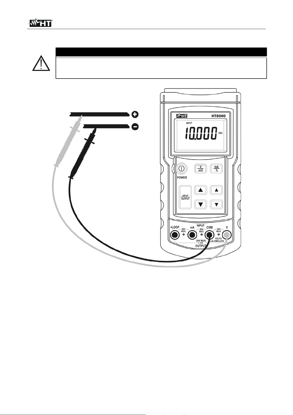
Fig. 2: DC Voltage measurement
1. Press INPUT/OUTPUT key and select the measurement mode. The “INPUT” symbol is
displayed
2. Press V/mV key and select the desired measurement unit. The symbol “V” or “mV” is
displayed
3. Insert the red plug into V jack and the black plug into COM jack
4. Connect the red and black test leads to the positive and negative poles of the circuit
under test respectively (see Fig. 2). The voltage value will be displayed
5. The message "O.L" means that the voltage exceeds the measuring limits. The symbol
"-O.L" on the display means that voltage has opposite polarity respect the connection
shown in Fig. 2
EN - 7
Page 9

HT8000
4.3.2. DC Voltage generation
Maximum input for DC voltage is 30V. Do not attempt to take any voltage
measurement exceeding such limit to avoid the risk of electrical shock and
damages to the instrument.
CAUTION
Fig. 3: DC Voltage generation
1. Press INPUT/OUTPUT key and select the generation mode. The “OUTPUT” symbol is
displayed
2. Press V/mV key and select the desired measurement unit. The symbol “V” or “mV” is
displayed
3. By means arrow keys and (see Fig. 1 – parts 9, 10, 11 and 12) to set the value of
output generated voltage. The maximum set values are 100mV and 10V. The voltage
value will be displayed
4. Insert the red plug into V jack and the black plug into COM jack
5. Connect the red and black test leads to the positive and negative poles of the external
device respectively (see Fig. 3).
6. For the generation of a negative value of voltage connect the test leads in the opposite
direction than shown in Fig. 3
EN - 8
Page 10

HT8000
4.3.3. DC current measurement
Maximum input for DC current is 24mA. Do not attempt to take any current
measurement exceeding such limit to avoid the risk of electrical shock and
damages to the instrument
CAUTION
Fig. 4: DC current measurement
1. Switch OFF the circuit under test
2. Press INPUT/OUTPUT key and select the measurement mode. The “INPUT” symbol is
displayed
3. Press mA/% key and select the desired measurement unit. The symbol “mA” or “mA%”
is displayed
4. Insert the red plug into mA jack and the black plug into COM jack
5. Connect red and black plugs in series with the circuit under test respecting the polarity
and current flow (see Fig. 4).
6. Power the circuit under test. The current value will be displayed
7. The message "O.L" means that the current exceeds the measuring limits. The symbol
"-O.L" on the display means that current has opposite direction than shown in Fig. 4
EN - 9
Page 11
HT8000
4.3.4. DC current generation
The maximum DC current generated by the instrument is 24mA with DC
voltage of current generator max 24VDC
CAUTION
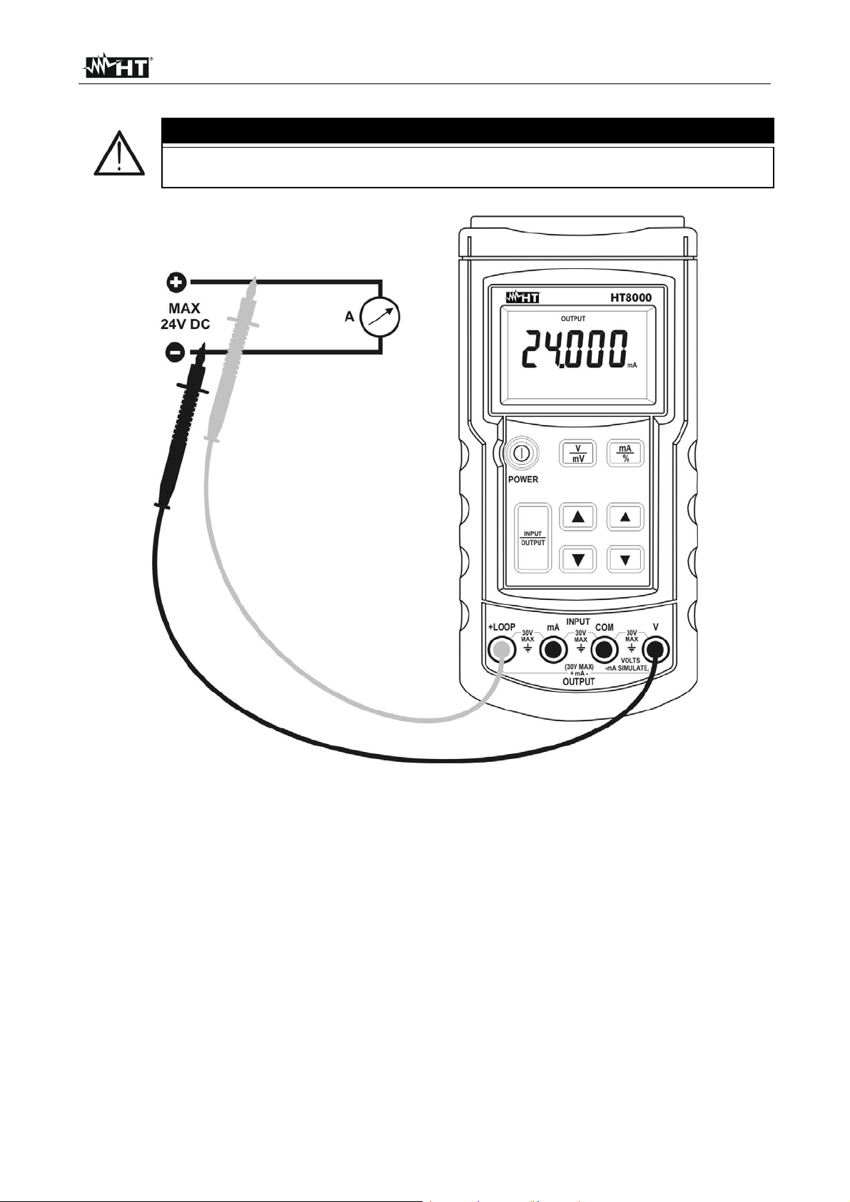
Fig. 5: DC current generation
1. Press INPUT/OUTPUT key and select the generation mode. The “OUTPUT” symbol is
displayed
2. Press mA/% key and select the desired measurement unit. The symbol “mA” or “mA%”
is displayed
3. Insert the red plug into +LOOP jack and the black plug into V jack
4. Connect the red and black test leads respectively to the positive and negative poles of
the external device which should receive the power supply (see Fig. 5)
5. By means arrow keys and (see Fig. 1 – parts 9, 10, 11 and 12) to set the value of
output generated current. The maximum set value is 24mA DC. For the “mA%” output
consider that -25% = 0mA, 0% = 4mA, 100% = 20mA and 125% = 24mA. The current
value will be displayed
6. For the generation of a negative value of current connect the test leads in the opposite
direction than shown in Fig. 5
EN - 10
Page 12

HT8000
4.3.5. Loop current measurement of external transducers
CAUTION
In this mode the instrument generate a fixed output voltage of 24VDC
which permits to supply an external transducer and perform the
simultaneous current measurement on it
Maximum input for DC current is 24mA. Do not attempt to take any current
measurement exceeding such limit to avoid the risk of electrical shock and
damages to the instrument
Fig. 6: Loop current measurement of external transducers
1. Switch OFF the circuit under test
2. Press INPUT/OUTPUT key and select the measurement mode. The “INPUT” symbol is
displayed
3. Press mA/% key and select the desired measurement unit. The symbol “mA” or “mA%”
is displayed
4. Insert the red plug into +LOOP jack and the black plug into mA jack
5. Connect red and black plugs to the external transducer respecting the polarity and
current flow (see Fig. 6).
6. Power the circuit under test. The current value will be displayed
7. The message "O.L" means that the current exceeds the measuring limits. For the
generation of a negative value of voltage connect the test leads in the opposite
direction than shown in Fig. 6
EN - 11
Page 13

HT8000
4.3.6. Simulating of a transducer
In this mode the instrument generate a output current up to 24mADC. It is
necessary the use of a external power supply with 30VDC maximum voltage
to perform the adjustment of the current
CAUTION
Fig. 7: Simulating of a transducer
1. Press INPUT/OUTPUT key and select the generation mode. The “OUTPUT” symbol is
displayed
2. Press mA/% key and select the desired measurement unit. The symbol “mA” or “mA%”
is displayed
3. Insert the red plug into V jack and the black plug into COM jack
4. Connect the red and black test leads respectively to the positive of the external power
supply and positive pole of the external measurement device (e.g. multimeter – see Fig.
7)
5. By means arrow keys and (see Fig. 1 – parts 9, 10, 11 and 12) to set the value of
output generated current. The maximum set value is 24mA DC with DC voltage fixed to
24V DC. For the “mA%” output consider that -25% = 0mA, 0% = 4mA, 100% = 20mA
and 125% = 24mA. The current value will be displayed
6. For the generation of a negative value of current connect the test leads in the opposite
direction than shown in Fig. 7
EN - 12
Page 14

HT8000
5. MAINTENANCE
5.1. GENERAL INFORMATION
1. This is a precision instrument. To guarantee its performances be sure to use it
according to these instructions and keep it stored on suitable environmental conditions.
2. Do not expose it to high temperatures or humidity or direct sunlight.
3. Be sure to turn it off after use. If you expect not to use the instrument for a long period
remove batteries to avoid leakages of battery liquid which could damage the its inner
components.
5.2. BATTERY REPLACEMENT
When the symbol " " is displayed, battery need replacement.
Before replacing battery disconnect the test leads from any energized
circuits to avoid electrical shocks
1. Switch OFF the meter
2. Disconnect the test leads from the input terminals
3. Unscrew the fixing screw and remove the cover of battery case
4. Disconnect the battery and insert a new battery of the same type (see § 6.1.2)
observing the proper polarity
5. Re-screw the cover of battery case
6. Use the appropriate battery disposal methods for your area
5.3. FUSES REPLACEMENT
The FUSE1 or FUSE2 replacement is necessary in the herewith situations:
FUSE1 On DC voltage generation no signal is given by the instrument
FUSE2 On DC current measurement the instrument always shows the
“0.000” indication with a input signal applied
FUSE2 On DC current generation the “OUTPUT” symbol is always
blinking at display and no signal is given by the instrument
1. Turn OFF the meter
2. Disconnect the test leads from the input terminals
3. Unscrew the fixing screw and remove the cover of battery case
4. Unscrew the four fixing screws and remove the lower part of the case
5. Unscrew the two fixing screws of the PCB internal protection and remove it
6. Remove the defective fuse and install a new fuse of the same size (see § 6.1.2)
7. Re-screw the PCB internal protection
8. Re-screw the lower part of the case
9. Re-screw the cover of battery case
5.4. CLEANING
To clean the instrument use a soft dry cloth. Never use a wet cloth, solvents or water.
5.5. END OF LIFE
CAUTION
CAUTION
CAUTION: this symbol indicates that equipment its accessories and battery shall
be subject to a separate collection and correct disposal
EN - 13
Page 15
HT8000
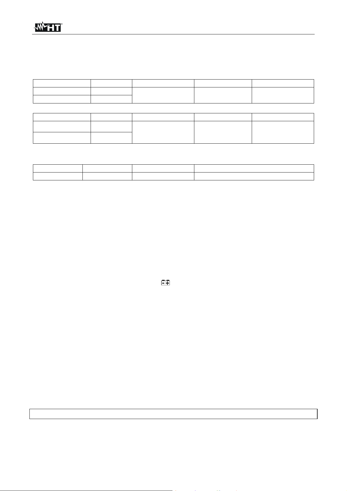
6. TECHNICAL SPECIFICATIONS
6.1. TECHNICAL FEATURES
Accuracy calculated as [%rdg + (no. dgt x resol.)] at 18°C28°C (64°F 82°F), <75%RH
DC Voltage (measured and generated)
Range Resolution Accuracy Input impedance Overload protection
0.01100.00mV
0.00110.000V
DC Current (measured and generated)
Range Resolution Accuracy Pe r c e n ta g e v a l u e O v e r load protection
0.00124.000mA
-25.00 125.00%
Source mode: 1000 @ 20mA (battery voltage 6.8V) ; 700 @ 20mA (battery voltage within 5.8V and 6.8V)
Simulating mode: required loop voltage: 24V nominal, 30V maximum, 12V minimum
Loop mode
Range Resolution Accuracy Overload protection
24V DC Not necessary
6.1.1. Reference standards
Safety: IEC/EN61010-1
Insulation: double insulation
Pollution degree: 2
Max height of use: 3000m (9843 ft)
6.1.2. General data
Mechanical characteristics
Dimensions (L x W x H): 190 x 89 x 42mm, 7 x 4 x 2 inches
Weight (including battery): 350g (12 ounces)
Power supply
Battery type: 1x9V alkaline NEDA1604, 006P, IEC6F22
Low battery indication: " " symbol is displayed
Battery life: 4 hours (1604 type), 2hours (006P type)
Auto Power OFF: after 6 minutes of idleness (disabled)
Display
Specifications: 5 LCD + symbol, decimal point
Over range indication: “O.L” message at display
Negative value indication: “-O.L” message at display for the herewith values:
<-2mV [100mV], <-0.2V [10V], <-1mA [24mA]
Fuses type FF 125mA/250V, 5x20mm, 0.03kA
6.2. ENVIRONMENT
6.2.1. Environmental conditions
Reference temperature: 18°C 28°C ; (64°F 82°F)
Working temperature: -10 ÷ 55°C ; (14°F ÷ 131°F)
Relative humidity: <75%RH
Storage temperature: -40 ÷ 60°C ; (-40°F ÷ 140°F)
This product conforms to the prescriptions of the EMC directive 2004/108/EEC
6.3. ACCESSORIES
Couple of test leads – Cod. KIT4000A User manual
Battery
0.01mV
0.001V
0.001mA
0.01%
(0.02rdg +2dgt) 2M, <100pF
0% = 4mA
(0.015%rdg+4dgt)
100% = 20mA
125% = 24mA
10%
30VDC
Fast fuse
125mA, 250V
30VDC
EN - 14
Page 16

HT8000
7. SERVICE
7.1. WARRANTY CONDITIONS
This instrument is guaranteed for one year against material or production defects, in
accordance with our general sales conditions. During the warranty period the manufacturer
reserves the right to decide either to repair or replace the product.
Should you need for any reason to return back the instrument for repair or replacement
take prior agreements with the local distributor from whom you bought it. Do not forget to
enclose a report describing the reasons for returning (detected fault). Use only original
packaging. Any damage occurred in transit due to non original packaging will be charged
anyhow to the customer.
The warranty doesn’t apply to:
Accessories and batteries (not covered by warranty).
Repairs made necessary by improper use (including adaptation to particular
applications not foreseen in the instructions manual) or improper combination with
incompatible accessories or equipment.
Repairs made necessary by improper shipping material causing damages in transit.
Repairs made necessary by previous attempts for repair carried out by non skilled or
unauthorized personnel.
Instruments for whatever reason modified by the customer himself without explicit
authorization of our Technical Dept.
Use not provided by the instrument's specifications or in the instruction manual.
The contents of this manual may not be reproduced in any form whatsoever without the
manufacturer’s authorization.
Our products are patented and our logotypes registered. We reserve the right to
modify specifications and prices in view of technological improvements or
developments which might be necessary.
7.2. SERVICE
Shouldn’t the instrument work properly, before contacting your distributor make sure that
batteries are correctly installed and working, check the test leads and replace them if
necessary.
Should you need for any reason to return back the instrument for repair or replacement
take prior agreements with the local distributor from whom you bought it.
Do not forget to enclose a report describing the reasons for returning (detected fault). Use
only original packaging. Any damage occurred in transit due to non original packaging will
be charged anyhow to the customer.
The manufacturer will not be responsible for any damage to persons or things.
EN - 15
 Loading...