

Page 1

ENGLISH
User manual
Copyright HT ITALIA 2013 Release EN 2.00 - 02/01/2013
Page 2

Page 3

HT7052
Table of Content:
1 PRECAUTIONS AND SAFETY MEASURES .............................................................................. 2
1.1 Preliminary instructions ........................................................................................................................ 2
1.2 During use ............................................................................................................................................ 3
1.3 After use ............................................................................................................................................... 3
1.4 Definition of measurement (overvoltage) category .............................................................................. 3
2 GENERAL DESCRIPTION .......................................................................................................... 4
2.1 Instrument features .............................................................................................................................. 4
3 PREPARATION FOR USE .......................................................................................................... 5
3.1 Initial inspections .................................................................................................................................. 5
3.2 Instrument power supply ...................................................................................................................... 5
3.3 Calibration ............................................................................................................................................ 5
3.4 Storage ................................................................................................................................................. 5
4 DESCRIPTION OF PARTS .......................................................................................................... 6
4.1 Instrument description .......................................................................................................................... 6
4.2 Description of test leads ....................................................................................................................... 7
5 INITIAL OPERATIONS ................................................................................................................ 8
5.1 Switching on the instrument ................................................................................................................. 8
5.1.1 Mains powered instrument operation ................................................................................................ 8
5.1.2 Backlight operation ............................................................................................................................ 8
5.1.3 Autocalibration ................................................................................................................................... 8
5.2 Configuration and Setup of systems parameters ................................................................................. 9
6 HOW TO PERFORM THE MEASUREMENTS .......................................................................... 10
6.1 Theory of insulation resistance measurement ................................................................................... 10
6.1.1 Time dependence test – Diagnostic test ......................................................................................... 12
6.1.2 Withstanding voltage test ................................................................................................................ 15
6.2 Guard terminal .................................................................................................................................... 16
6.3 Use of internal filters ........................................................................................................................... 17
6.3.1 The purpose of filtering .................................................................................................................... 17
6.4 Voltage measurement ........................................................................................................................ 18
6.5 Insulation resistance measurement ................................................................................................... 19
6.5.1 Setting of parameters ...................................................................................................................... 19
6.5.2 Perform the measurement ............................................................................................................... 20
6.6 Diagnostic test .................................................................................................................................... 22
6.6.1 Setting of parameters ...................................................................................................................... 22
6.6.2 Perform the measurement ............................................................................................................... 23
6.7 Insulation resistance with step voltage test ........................................................................................ 25
6.7.1 Setting of parameters ...................................................................................................................... 25
6.7.2 Perform the measurement ............................................................................................................... 26
6.8 Withstanding voltage test ................................................................................................................... 28
6.8.1 Setting of parameters ...................................................................................................................... 28
6.8.2 Perform the measurement ............................................................................................................... 29
7 MANAGEMENT OF MEMORY DATA ....................................................................................... 30
7.1 Saving, recall and clear measurement results ................................................................................... 30
8 CONNECTION OF THE INSTRUMENT TO PC ........................................................................ 31
8.1 Installation of software and initial configurations (Win XP) ................................................................ 31
9 MAINTENANCE ......................................................................................................................... 33
9.1 General information ............................................................................................................................ 33
9.2 Replacement and charging batteries ................................................................................................. 33
9.3 Cleaning the instrument ..................................................................................................................... 33
9.4 End of life............................................................................................................................................ 33
10TECHNICAL SPECIFICATIONS ............................................................................................... 34
10.1Safety standards ................................................................................................................................ 35
10.2General characteristics ....................................................................................................................... 36
10.3Environment ....................................................................................................................................... 36
10.4Accessories ........................................................................................................................................ 36
11SERVICE ................................................................................................................................... 37
11.1Warranty conditions ............................................................................................................................ 37
11.2Service ................................................................................................................................................ 37
EN - 1
Page 4
HT7052
1 PRECAUTIONS AND SAFETY MEASURES
The instrument has been designed in compliance with standards IEC/EN61557-1 and
IEC/EN61010-1 regarding electronic measuring instruments
For the operator’s safety and to prevent damaging the instrument, follow the
procedures described in this manual and carefully read all notes preceded by
the symbol
Before and during measurements, carefully observe the following instructions:
Do not perform any measurement in humid environments, in the presence of gas or
explosive or inflammable material or in dusty areas
Even when no measurements are being performed, avoid any contact with the circuit
being tested, with exposed metal parts, with unused measuring leads or circuits, etc
Do not perform any measurement when anomalies are found in the instrument, such as
deformations, breaks, substance leaks, no display view, etc
Pay special attention when measuring voltages above 25V in special environments
(building yards, swimming pools, etc.) and 50V in ordinary environments, as there is the
danger of electric shocks
In this manual and on the instrument, the following symbols are used:
WARNING: Observe the instructions reported in the manual. An improper use
could damage the instrument and lead to dangerous situations for the operator
DC voltage or current
CAUTION
Dangerous voltages: risk of electric shocks
Instrument with double insulation
1.1 PRELIMINARY INSTRUCTIONS
This instrument has been designed for use in an environment with pollution level 2
It may also be used to test industrial electrical systems up to CAT IV 600V to earth with
maximum voltage 600V between inputs
Follow the usual safety rules to protect the operator from dangerous currents and
protect the instrument against improper use
Never use the instrument resting on the floor, it must be placed over flat horizontal
surfaces
Only the accessories supplied with the instrument guarantee safety standards. They
must be in good conditions and replaced, if necessary, with identical models
Do not measure systems exceeding the current and voltage limit values specified
Do not perform measurements in environmental conditions not within the limit values
indicated in this manual
Before connecting the probes to the circuit to be tested, check that the correct function
is selected
EN - 2
Page 5
HT7052
1.2 DURING USE
Carefully read the following recommendations and instructions:
CAUTION
Failure to observe the warnings and/or instructions may damage the
instrument and/or its components or generate a danger for the operator. If,
during use, the low battery symbol appears on the display, insert the supply
cable into the Europlug socket to start battery recharge. During battery
recharge, it is possible to perform measurements
Before selecting a new function, disconnect the measuring probes from the circuit
When the instrument is connected to the circuit being tested, never touch any unused
lead
Avoid measuring resistance with external voltages. Even if the instrument is protected,
as an excess voltage may cause instrument malfunctions
In case of a capacitive test object (long tested cable etc.), automatic discharge of the
object may not be done immediately after finishing the measurement – “Please wait,
discharging” message will be displayed
Handling with capacitive loads note that 40nF charged to 1kV or 5nF charged to 10 kV
are hazardous live
1.3 AFTER USE
When measurements are completed, turn off the instrument by pressing the ON/OFF key
1.4 DEFINITION OF MEASUREMENT (OVERVOLTAGE) CATEGORY
Standard "IEC/EN61010-1: Safety requirements for electrical equipment for measurement,
control and laboratory use, Part 1: General requirements", defines what is intended for
measurement category, commonly known as overvoltage category. In § 6.7.4: Measuring
circuits, it reads:
Circuits are divided into the following measurement categories:
Measurement category IV is for measurements performed at the source of a low-
voltage installation
Examples are electric counters and measurements on primary devices protecting
against overcurrents and on ripple adjusting units
Measurement category III is for measurements performed on installations inside
buildings
Examples are measurements performed on distribution boards, circuit breakers, wiring
harnesses, including cables, bars, junction boxes, switches, sockets of fixed
installations and appliances designed for industrial use and other equipment, e.g.
stationary motors connected to fixed systems
Measurement category II is for measurements performed on circuits directly
connected to the low-voltage installation
Examples are measurements performed on household appliances, portable tools and
similar equipment
Measurement category I is for measurements performed on circuits not directly
connected to the MAINS
Examples are measurements performed on circuits not derived from the MAINS and on
circuits derived from the MAINS provided with a special (internal) protection. In this
latter case, the stress caused by the transients is variable; therefore, (OMISSIS) it is
necessary that the user knows the appliance’s resistance to transients
EN - 3
Page 6

HT7052
2 GENERAL DESCRIPTION
The instrument HT7052 You purchased, if used in compliance with the indications given in
this manual, guarantees accurate and reliable measurements and the utmost safety
thanks to a development of new conception which ensures double insulation and,
consequently, compliance with the requirements of overvoltage category IV
2.1 INSTRUMENT FEATURES
High insulation resistance measurement up to 10 T
Programmable test voltage from 500V up to 10 kV, step 25 V
R(t) Graphs
Programmable timer (1s up to 30 min)
Automatic discharge of test object after completion of measurement
Capacitance measurement
Insulation resistance measurement with step-up voltage test
Five discrete test voltages proportionately set within preset test voltage range
Programmable timer 1 min up to 30 min per step
Polarization Index (PI), Dielectric Absorption ratio (DAR) and Dielectric Discharge (DD)
ratio measurements
PI = Rins (t2) / Rins (t1)
DAR = R1min / R15s
DD = Idis1min / C*U
Withstanding voltage (DC) up to 10 kV
Programmable ramp test voltage from 500 V up to 10 kV
High resolution ramp (approx. 25 V per step)
Programmable threshold current up to 5mA
Voltage and frequency measurement up to 600 V AC/DC
A dot matrix LCD offers easy-to-read results and all associated parameters. The operation
is straightforward and clear to enable the user to operate the instrument without the need
for special training (except reading and understanding this user manual)
Test results can be stored on the instrument. The new professional PC SW enables
straightforward transfer of test results and other parameters in both directions between the
test instrument and PC
EN - 4
Page 7
HT7052
3 PREPARATION FOR USE
3.1 INITIAL INSPECTIONS
Before shipment, the instrument’s electronics and mechanics have been inspected. All
possible precautions have been taken in order for the instrument to be delivered without
damage
However, we recommend generally inspecting the instrument in order to detect any
damage suffered during transport. Should you detect any anomalies, immediately contact
the forwarding agent or the dealer
Moreover, we recommend checking that the package contains all parts listed in § 10.4.
Should you find any discrepancy, please contact the dealer. Should it become necessary
to return the instrument, please follow the instructions reported in § 11
3.2 INSTRUMENT POWER SUPPLY
The instrument is power-supplied through 6x1.2V IEC LR20 NiMH internal rechargeable
batteries which are recharged from the mains by means of a battery charger integrated in
the instrument itself. The symbol “ “ illuminated in the left bottom part indicates that
the batteries are flat and must be recharged. To recharge or replace the batteries, follow
the instructions given in § 10.2
Use only NiMh rechargeable batteries (IEC LR20)
Connect the instrument to the mains power supply for 20 hours to fully
charge batteries (typical charging current is 600mA). When you charge the
batteries for the first time, it normally takes about 3 charge and discharge
cycles for the batteries to regain full capacity
CAUTION
3.3 CALIBRATION
The instrument complies with the technical specifications reported in this manual. Its
correct operation is guaranteed for one year from the date of purchase
3.4 STORAGE
In order to guarantee accurate measurements and protect the instrument from possible
failures, after a long storage period under extreme environmental conditions, wait for the
instrument to return to a normal condition (see the environmental specifications listed in §
0)
EN - 5
Page 8
HT7052
4 DESCRIPTION OF PARTS
4.1 INSTRUMENT DESCRIPTION
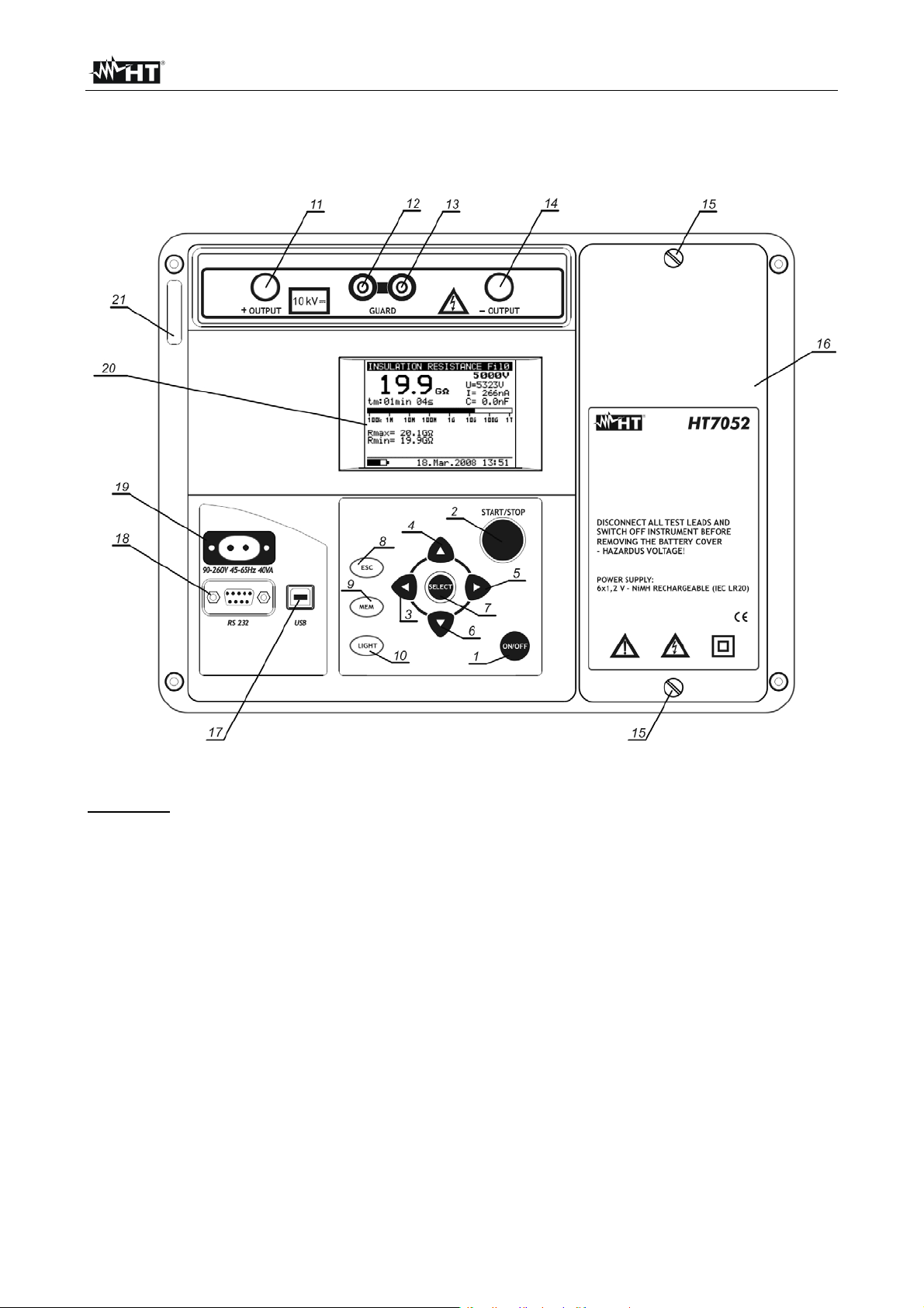
Fig. 1: Instrument description
LEGEND:
1 ON/OFF key to switch the instrument ON or OFF
2 START/STOP key to start or stop any measurement
3-4-5-6 , , , arrow keys to select parameters and set values
7 SELECT key to enter set-up mode parameters
8 ESC key to exit the selected mode
9 MEM key to store, recall and erase results
10 Light key to turn the display backlight ON or OFF
11 Positive insulation resistance test terminal +OUTPUT
12 -13 GUARD test terminals intended to lead away potential leakage current
14 Negative insulation resistance test terminal –OUTPUT
15 Screw to fixing battery cover
16 Battery cover
17 USB galvanic port for connection to PC
18 RS-232 galvanic port for connection to PC
19 Mains connector to connect the instrument to the mains supply
20 LCD display
21 Label with serial number of the instrument
EN - 6
Page 9
HT7052
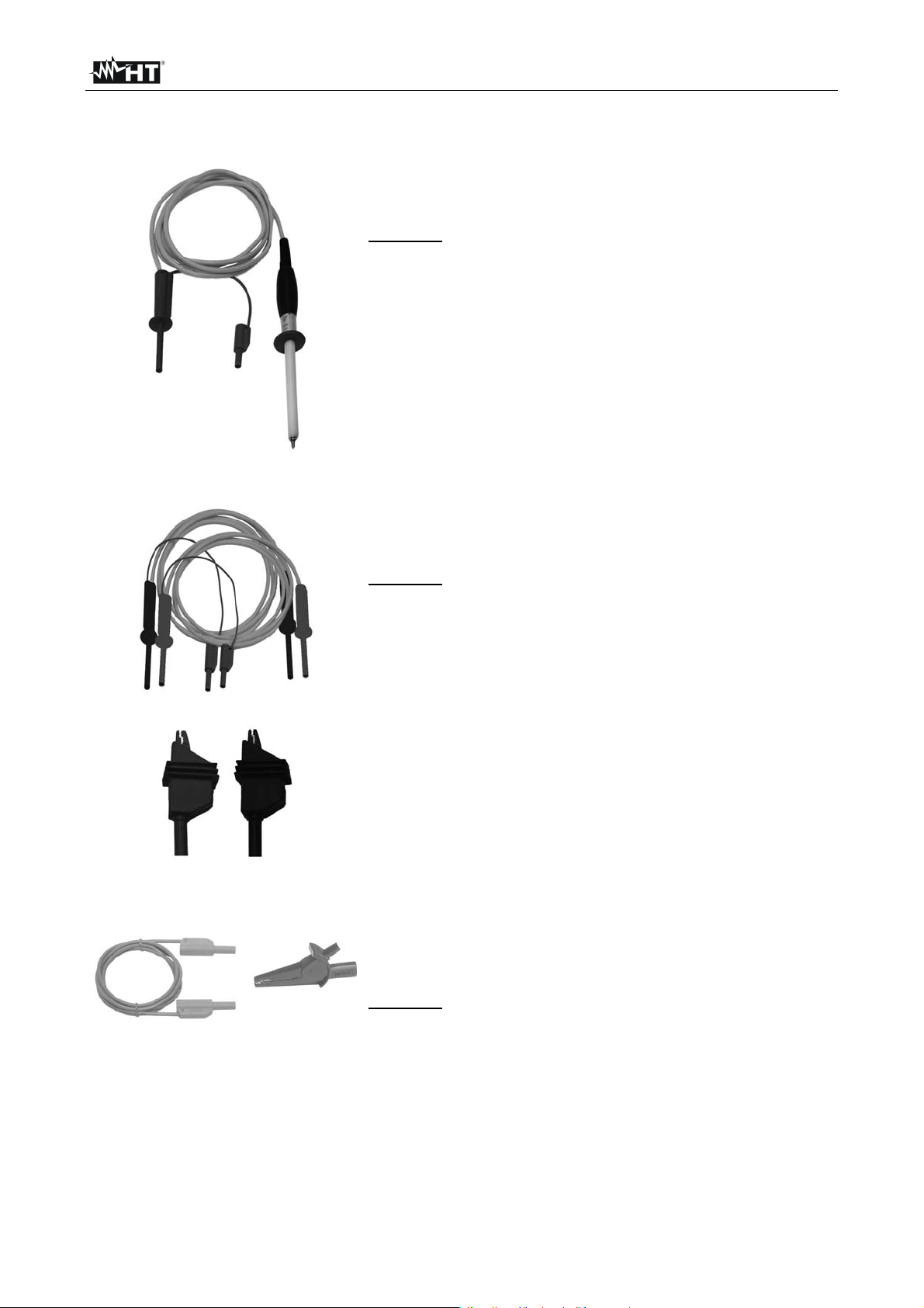
4.2 DESCRIPTION OF TEST LEADS
Test lead 1
This test lead is designed for hand held testing of
insulation resistance
Features
Shielded cable in order to increase the immunity to
external disturb and improve the accuracy of
measurements
Insulation of yellow shielded cable: 12kVDC
Length cable = 2m
Test lead with double insulation and protection
10kVDC
Red banana connector with basic protection 10kVDC
and double protection 5kVDC
Test leads 2
Guard test lead
Green guard banana connector: CAT IV 600V
These test leads is designed for diagnostic testing of
insulation
Features
Shielded cables in order to increase the immunity to
external disturb and improve the accuracy of
measurements
Insulation of yellow shielded cables: 12kVDC
Length cables = 2m
Red/black banana connectors with basic protection
10kVDC and double protection 5kVDC
Green guard banana connectors: CAT IV 600V
Red/Black alligator clips with basic protection
10kVDC and double protection 5kVDC
This test lead is used in connection with the object on
test in order to reduce or cancel the surface leakage
current (see § 6.2)
Features
Cable banana-banana with protection CAT IV 600V
Alligator clip CAT IV 600V
EN - 7
Page 10
HT7052
5 INITIAL OPERATIONS
5.1 SWITCHING ON THE INSTRUMENT
5.1.1 Mains powered instrument operation
If you connect instrument to the mains supply when instrument is turned
OFF, internal charger will begin to charge the batteries but instrument will
remain turned OFF. In button left angle of LCD, flashing battery indicator
will appear to indicate that the batteries are charging
If batteries are defective or missing and the instrument is connected
to the mains, the instrument do not switch on
If batteries are defective or missing, the charger will not work. In
button left corner of LCD screen only plug character will be appeared
If the instrument is connected to the mains supply when the instrument is
turn ON, the instrument will automatically switch from the battery supply to
the main supply. In button left corner of the LCD screen, the plug character
will appear
If instrument is not in measuring mode*, the internal charger will begin to
charge the batteries. In button left corner of LCD screen battery indicator
will start to flash, indicating that the batteries are charging
It is recommended to DO NOT connect or disconnect the instrument to
mains supply while the instrument is in measuring mode
5.1.2 Backlight operation
Instrument supplied by the batteries
After turning the instrument ON the LCD backlight is automatically turned ON. It can be
turned OFF and ON by simply clicking the LIGHT key
Instrument supplied by the mains
After turning the instrument ON the LCD backlight is automatically turned OFF. It can be
turned OFF and ON by simply clicking the LIGHT key
Auto power OFF
The instrument can be switched OFF only by pressing the ON/OFF key. The auto-off
function is not available to allow long-term measurements to be performed
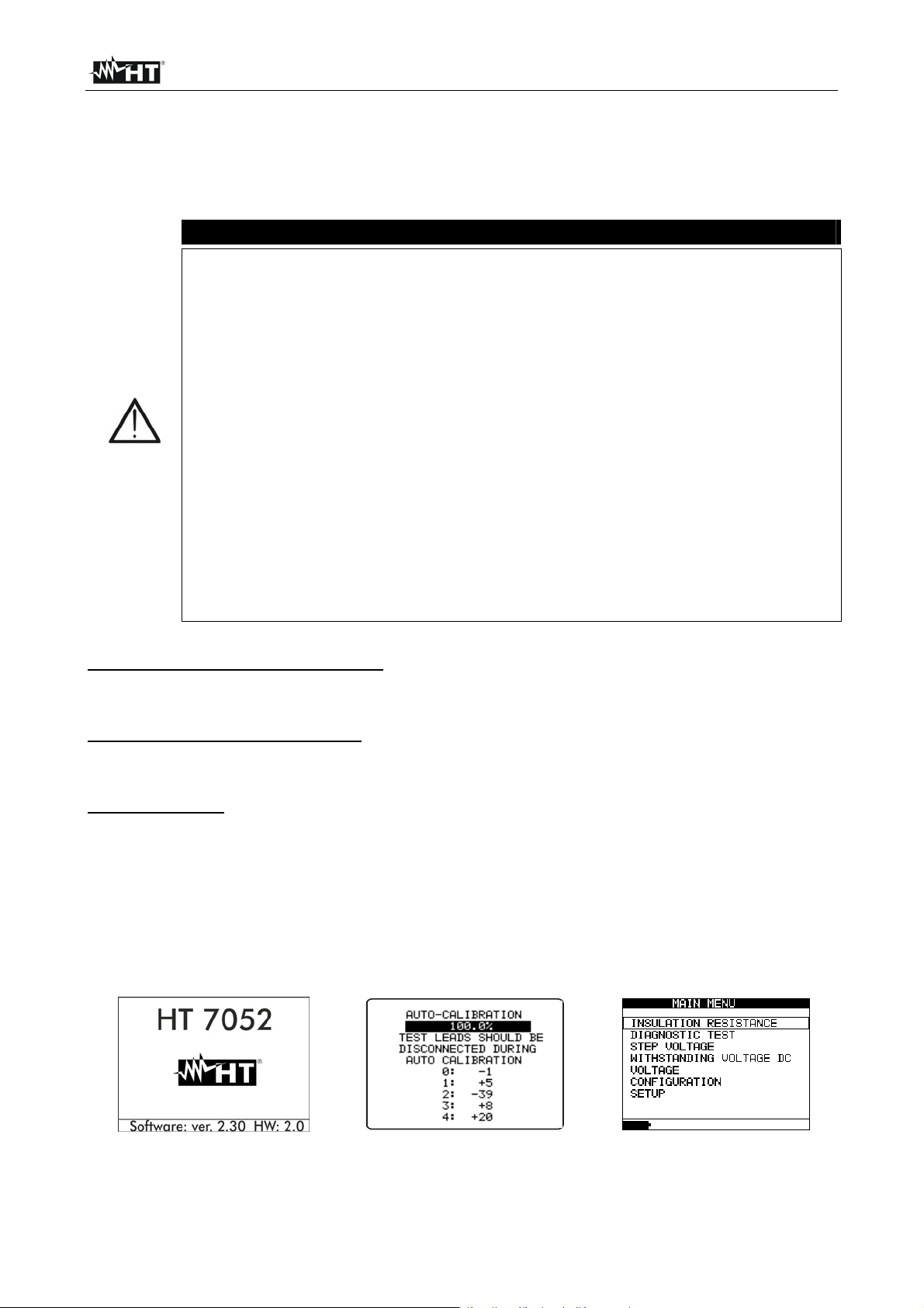
5.1.3 Autocalibration
The instrument is switched ON by pressing the ON/OFF key. After turning on, the
instrument will perform the autocalibration (see Fig. 3). Measuring test leads should be
disconnected during autocalibration. If not, the autocalibration procedure could be false
and instrument will require disconnection of the test leads and repeat switching OFF and
ON
CAUTION
Fig. 2: Spash screen Fig. 3: Autocalibration Fig. 4: Main menu
After finishing the autocalibration, the main menu (see Fig. 4) will appear and instrument
is ready for normal operation
EN - 8
Page 11
HT7052
Auto-calibration prevents the reduction in accuracy when measuring very low currents. It
compensates the effects caused by ageing, temperature and humidity changes etc. A new
auto-calibration is recommended when the temperature changes by more than 5C. If the
instrument detects an incorrect state during the autocalibration, the following warning
message will be displayed:
CAUTION
TEST LEADS CONNECTED: DISCONNECT AND SWITCH ON THE
INSTRUMENT AGAIN
CONDITIONS OUT OF RANGE: PRESS START TO CONTINUE
Possible reasons for out of range conditions are excessive humidity, excessively high
temperature, etc. In this case it is possible to perform measurements by pressing the
START/STOP button again but results could be out of technical specification
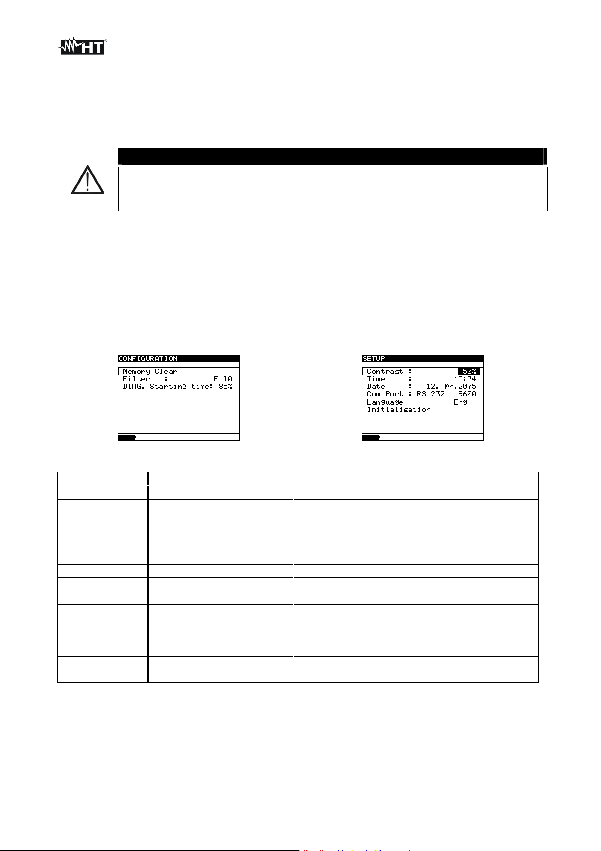
5.2 CONFIGURATION AND SETUP OF SYSTEMS PARAMETERS
The configuration and setup function enables the selection and adjustment of the
parameters (see Table 1) that are not directly involved in the measurement procedure (see
Fig. 5 and Fig. 6). In the lower section of the display the power supply status is shown
Fig. 5: Configuration menu Fig. 6: Setup menu
PARAMETERS VALUE DESCRIPTION
Memory clear
Filter
DIAG. Starting
time
Contrast
Time
Date
COM port
Language
Initialization
Fil1, Fil2, Fil3, Fil0 Selection of noise rejecting filter (see § 6.3)
RS232 2400, RS232 4800,
RS232 9600,RS232 19200,
USB 115000
Ita, Eng, Esp, Deu Set system language
Clear all memory locations
Adjustment of start of the timer in the
0%…90%
0%…100% Adjustment of the LCD contrast
Set real time (hour: minute)
Set current date (day-month-year)
For internal factory and service maintenance
DIAGNOSTIC TEST functions, according to the
nominal voltage Unominal. See additional
explanation in § 6.1)
Set communication mode and rate
only
Table 1: Configuration of system parameters
1. Use and arrows to select parameter (line) to be adjusted
2. Use or arrows to change the value of the selected parameter. If there are two or
more sub-parameters in one line (e.g. date and time) then use the SELECT key to skip
to the next sub-parameters and back
3. Press the ESC key to exit from configuration and back to the main menu
EN - 9
Page 12
HT7052
6 HOW TO PERFORM THE MEASUREMENTS
6.1 THEORY OF INSULATION RESISTANCE MEASUREMENT
The purpose of insulation tests
Insulating materials are important parts of almost every electrical product. The material’s
properties depend not only on its compound characteristics but also on temperature,
pollution, moisture, ageing, electrical and mechanical stress, etc. Safety and operational
reliability require the regular maintenance and testing of the insulation material to ensure it
is kept in good operational condition.
materials
DC vs. AC testing voltage
Testing with a DC voltage is widely accepted as being useful as testing with AC and / or
pulsed voltages. DC voltages can be used for breakdown tests especially where high
capacitive leakage currents interfere with measurements using AC or pulsed voltages. DC
is mostly used for insulation resistance measurement tests. In this type of test, the voltage
is defined by the appropriate product application group. This voltage is lower than the
voltage used in the withstanding voltage test so the tests can be applied more frequently
without stressing the test material
Typical insulation tests
In general, insulation resistance tests consist of the following possible procedures:
Simple insulation resistance measurement also called a spot test
Measurement of the relationship between voltage and insulation resistance
Measurement of the relationship between time and insulation resistance
Test of residual charge after the dielectric discharge
The results of this test can indicate whether the replacement of the insulation system is
required. Typical examples of where testing insulation resistance and its diagnosis are
recommended are transformer and motor insulation systems, cables and other electrical
equipment
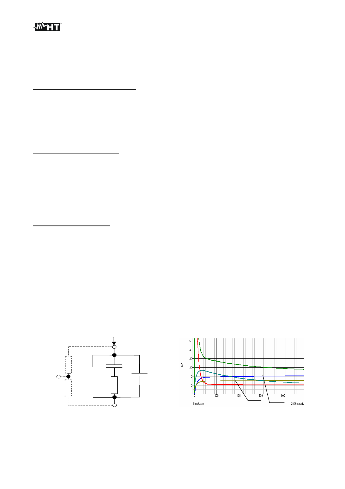
Electrical representation of insulating material
The represents the equivalent electrical circuit of an insulating material
Guard
surface
Riss1
Riso
Riss2
Itest
+
Rpi
-
material
Cpi
Fig. 7: Equivalent electrical circuit Fig. 8: Current graphs
High voltage tests are used to test insulating
t
Ites
IPI
Ciso
I
Ciso
I
I
Riso
Riss
EN - 10
Page 13
HT7052
R
, R
iss1
R
= the actual insulation resistance of material
iso
C
= capacitance of material
iso
Cpi, Rpi = represents polarization effects
The Fig. 8 shows typical currents for that circuit, where:
I
= overall test current (I
test
I
= polarization absorption current
PI
I
RISO
I
RISS
= surface resistivity (position of optional guard connection)
iss2
= IPI+ I
test
RISO
+ I
RISS
)
= actual insulation current
= surface leakage current
Basic Insulation resistance test
Virtually every standard concerning the safety of electrical equipment and installations
requires the performance of a basic insulation testing. When testing lower values (in the
range of M), the basic insulation resistance (R
) usually dominates. The results are
iso
adequate and stabilize quickly
It is important to remember the following:
The voltage, time and limit are usually given in the appropriate standard or regulation
Measuring time should be set to 60 s or the minimum time required for the Insulation
capacitance Ciso to be charged up
Sometimes it is required to take ambient temperature into account and adjust the result
for a standard temperature of 40C
If surface leakage currents interfere with the measurements (see Riss above) use the
guard connection (see § 5.2.). This becomes critical when measured values are in the G
range
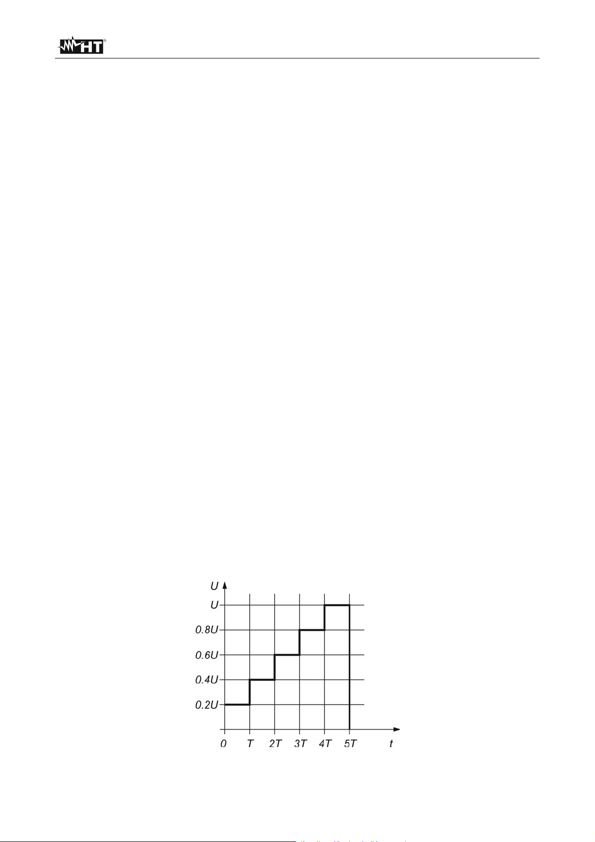
Voltage dependence test – Step voltage test
This test shows if the insulation under test has been electrically or mechanically stressed.
In this instance the quantity and size of insulation anomalies (e.g. cracks, local
breakdowns, conductive parts, etc). is increased and the overall breakdown voltage is
reduced. Excessive humidity and pollution have an important role especially in the case of
mechanical stress. If the results of successive tests show a reduction in the tested
insulation resistance the insulation should be replaced
In this function the instrument measure the insulation resistance by considering 5 equal
time intervals with the test voltage divided from 1/5 of nominal value to the set nominal
value (see Fig. 9)
Fig. 9: Insulation measurement with step voltage test
EN - 11
Page 14
HT7052
R
6.1.1 Time dependence test – Diagnostic test
Diagnostic test is a long duration test for evaluating the quality of the insulation material
under test. The results of this test enable the decision to be made on the preventive
replacement of the insulation material
DIELECTRIC ABSORPTION RATIO (DAR)
DAR is ratio of Insulation Resistance values measured after 15s and after 1 minute. The
DC test voltage is present during the whole period of the test (also an Insulation
Resistance measurement is continually running). At the end, the DAR ratio is displayed:
iso
15
iso
s
tC10
U
min1
s
.
V
3
DAR
Some applicable values:
DAR value Tested material status
< 1.25 Not acceptable
< 1.6 Considered as good insulation
> 1.6 Excellent
When determining Riso (15s) pay attention to the capacitance of the test object. It has to
be charged-up in the first time section (15s). Approximate maximum capacitance using:
max
where:
t = period of first time unit (e.g. 15s)
U = test voltage.
To avoid this problem, increase the DIAG. Starting time parameter in CONFIGURATION
menu, because start of timer in the DIAGNOSTIC TEST functions depends on the test
voltage. The timer begins to run when test voltage reaches the threshold voltage, which is
product of the DIAG. Starting time and nominal test voltage (Unominal)
Using filters (fil1, fil2, fil3) in the DAR function is not recommended!
Analysing the change in the measured insulation resistance over time and calculating the
DAR and PI are very useful maintenance tests of an insulating material
R
F
EN - 12
Page 15
HT7052
R
POLARIZATION INDEX (PI)
PI is the ratio of Insulation Resistance values measured after 1 minute and after 10
minutes. The DC test voltage is present during the whole period of the measurement (an
Insulation Resistance measurement is also running). On completion of the test the PI ratio
is displayed:
R
PI
General applicable values:
PI value Tested material status
1 to 1.5 Not acceptable (older types)
2 to 4 (typically 3) Considered as good insulation (older types)
>4(very high insulation resistance) Modern type of (good) insulation systems
When determining Riso (1min) pay close attention to the capacitance of the object under
test. It has to be charged-up in the first time section (1 min). Approximate maximum
capacitance using:
F
max
where:
t = period of first time unit (e.g. 1min)
U = test voltage
To avoid this problem, increase the DIAG. Starting time parameter in CONFIGURATION
menu, because start of timer in the DIAGNOSTIC TEST functions depends on the test
voltage. The timer begins to run when test voltage reaches the threshold voltage, which is
product of the DIAG. Starting time and nominal test voltage (Unominal)
min10
iso
min1
iso
tC10
U
s
.
V
3
EN - 13
Page 16
HT7052
DIELECTRIC DISCHARGE RATIO (DD)
An additional effect of polarization is the recovered charge (from Cpi) after the regular
discharging of a completed test. This can also be a supplementary measurement for
evaluation of the quality of insulating material. This effect is generally found in insulating
systems with large capacitance Ciso. The polarisation effect (described in “Polarisation
Index”) causes a capacitance to form (Cpi). Ideally this charge would dissipate
immediately a voltage was removed from the material. In practice, this is not the case
DD is the diagnostic insulation test carried out after the completion of the Insulation
Resistance measurement. Typically the insulation material is left connected to the test
voltage for 10 30 min and then discharged before the DD test is carried out. After 1
minute a discharge current is measured to detect the charge re-absorption of the insulation
material. A high re-absorption current indicates contaminated insulation (mainly based on
moisture:
mAIdis
DD
where:
Idis 1min = discharging current measured 1 min after regular discharge
U= test voltage
C= capacitance of test object
General applicable values:
DD Value Tested material status
> 4 Bad
2 - 4 Critical
< 2 Good
min1
FCVU
.
EN - 14
Page 17
HT7052
6.1.2 Withstanding voltage test
Some standards allow the use of a DC voltage as an alternative to AC withstanding
voltage testing. For this purpose the test voltage has to be present across the insulation
under test for a specific time. The insulation material only passes if there is no breakdown
or flash over. Standards recommend that the test starts with a low voltage and reaches the
final test voltage with a slope that keeps the charging current under the limit of the current
threshold. The test duration normally takes 1 min
The instruments offers Withstanding Voltage test of insulation material. It covers two types
of tests:
Breakdown voltage testing of high voltage device, e.g. transient suppressors and
DC withstanding voltage test for insulation coordination purposes
Both functions require breakdown current detection. The test voltage increases step by
step from the Start up to the Stop value over a predefined time and it is kept at the Stop
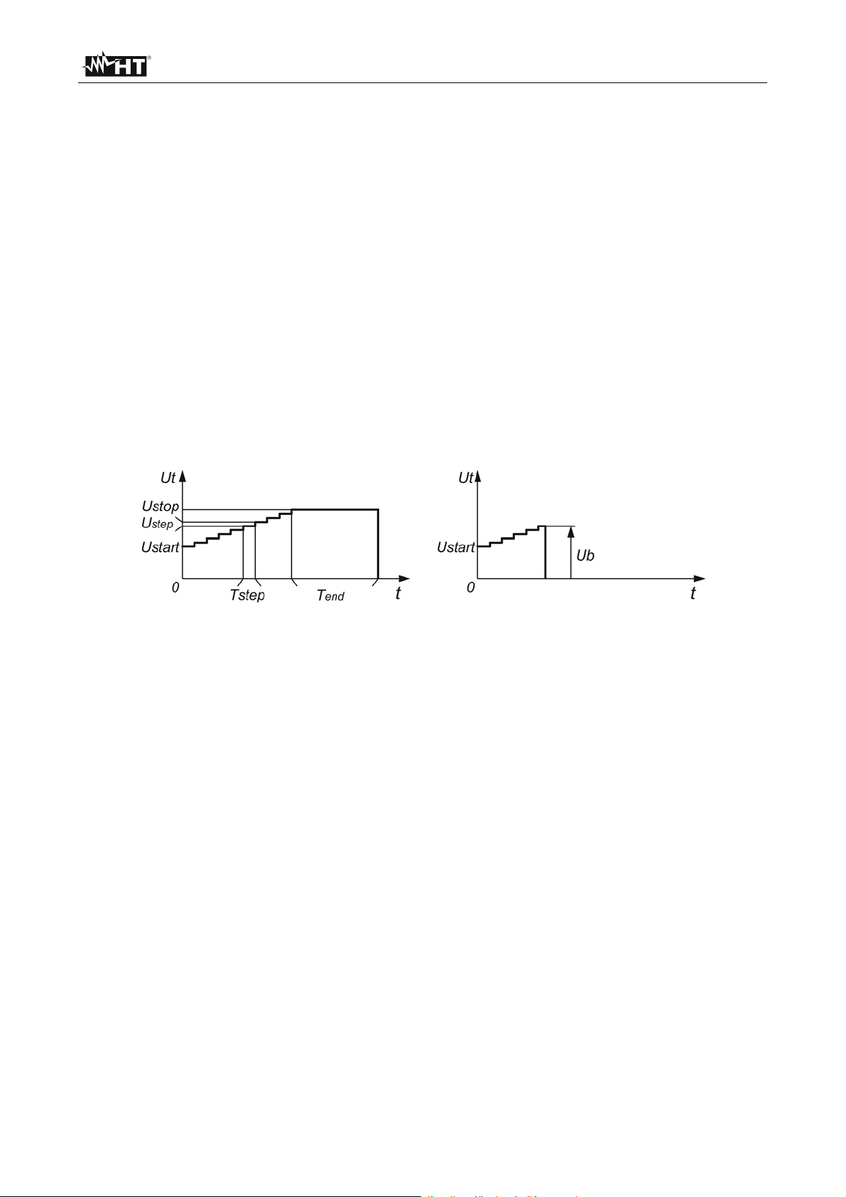
value for a predefined test time (see Fig. 10 – left part) or it happens the breakdown on
device under test (see Fig. 10 – right part)
Fig. 10: Withstanding test without breakdown (left) and with breakdown (right)
Ut = test voltage
t = time
Ustart = starting voltage
Ustep = voltage step approx. 25 V (fixed value - not modify)
Ustop = end test voltage
Tstep = test voltage duration per step
Tend = constant test voltage duration after reaching End value
Ub = breakdown voltage
Humidity and insulation resistance measurements
When testing outside the reference ambient conditions, the quality of the insulation
resistance measurements can be affected by humidity. Humidity adds leakage paths onto
the surface of the complete measuring system, (i.e. the insulator under test, the test leads,
the measuring instrument etc). The influence of humidity reduces accuracy especially
when testing very high resistances (e.g. T). The worst conditions arise in environments
containing high condensation, which can also reduce safety. In the case of high humidity, it
is recommended to ventilate the test areas before and during the measurements. In the
case of condensed humidity the measuring system must dry and it can take several hours
or even few days to recover
EN - 15
Page 18
HT7052
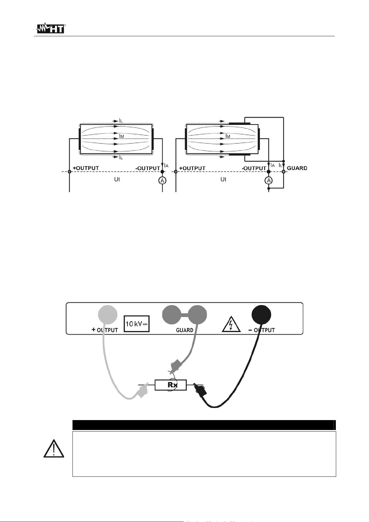
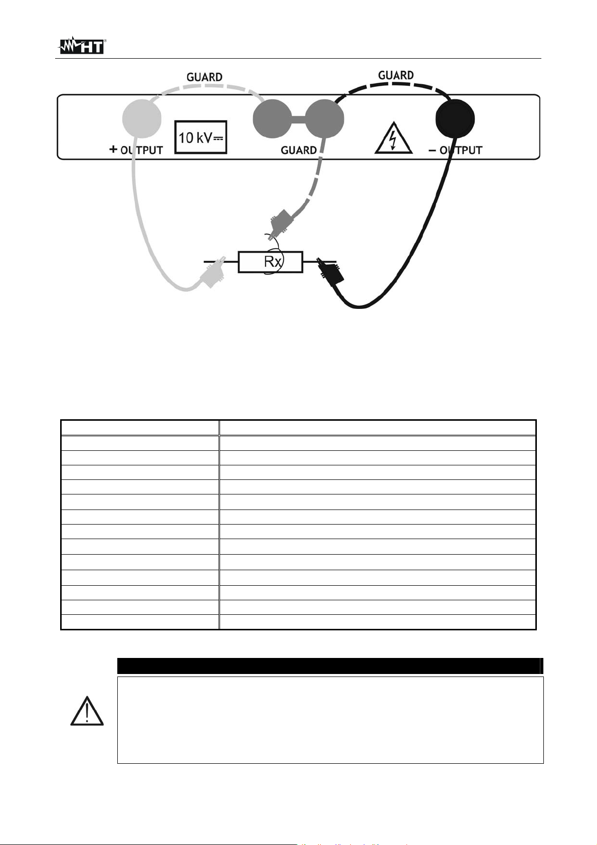
6.2 GUARD TERMINAL
The purpose of the GUARD terminal is to lead away potential leakage currents (e.g.
surface currents), which are not a result of the measured insulation material itself but are a
result of the surface contamination and moisture. This current interferes with the
measurement i.e. the Insulation Resistance result is influenced by this current. The
GUARD terminal is internally connected to the same potential as the negative test terminal
(black one). The GUARDs test clip should be connected to the test object so as to collect
most of the unwanted leakage current (see Fig. 11)
where:
Fig. 11: Principle scheme relative to the Guard terminal
Ut ..................... Test voltage
IL ...................... Leakage current (resulted by surface dirt and moisture)
IM ...................... Material current (resulted by material conditions)
IA ...................... Test current
Result without GUARD terminal: R
Result using GUARD terminal: R
= Ut / IA = Ut / (IM + IL) Incorrect result
INS
= Ut / IA = Ut / IM correct result
INS
The GUARD terminal it is internal connected at the same negative test lead (black). The
alligator clip should be connected to the object on test in way to detect the most possible
leakege current (see Fig. 12)
Fig. 12: Connection of the Guard terminal to the object on test
CAUTION
It is recommended to use the GUARD connection when high insulation
resistance (> 10G) should be measured
The guard terminal is protected by an internal impedance 400k
The instrument has two guard terminals to allow easy connection of
shielded measuring leads
EN - 16
Page 19
HT7052
A
6.3 USE OF INTERNAL FILTERS
Filters are built in to reduce the influence of noise on measurement results. This option
enables more stable results especially when dealing with high Insulation Resistances
(Insulation Resistance, Diagnostic Test, Step Voltage). In these functions, the status of the
filter option is shown in the top right corner of the LCD screen. The below table contains a
definition of the individual filter options
Filter options Description
Fil0 Low pass filter with cut off frequency of 0.5 Hz in signal line
Fil1
dditional low pass filter with cut off frequency of 0.05 Hz in
the signal line
Fil2 Fil1 with increased integrating time (4 s)
Fil3 Fil2 with additional cyclic averaging of 5 results
Table 2: Filter options
6.3.1 The purpose of filtering
The internal filters smooth the measured currents by means of averaging and bandwidth
reduction. There are various sources of disturbance:
AC currents at the mains frequency and its harmonics, switching transients etc, cause
the results to become unstable. These currents are mostly cross talk through insulation
capacitances close to live systems
Other currents induced or coupled in the electromagnetic environment of the insulation
under test
Ripple current from internal high voltage regulator,
Charging effects of high capacitive loads and / or long cables.
Voltage changes are relatively narrow on high resistance insulation, so the most important
point is to filter the measured current
CAUTION
Any of the selected filter options increases the settling time with Fil1 to 60
s, Fil2 to 70 s, and Fil3 to 120s
It is necessary to pay close attention to the selection of time intervals when
using the filters
The recommended minimum measuring times when using filters are the
settling times of the selected filter option
Example:
A noise current of 1mA/50Hz adds approximately 15% distribution to the measured result
when measuring 1G.
By selecting FIL1 option the distribution will reduce to less than 2 %
In general using FIL2 and FIL3 will further improve the noise reduction
EN - 17
Page 20
HT7052
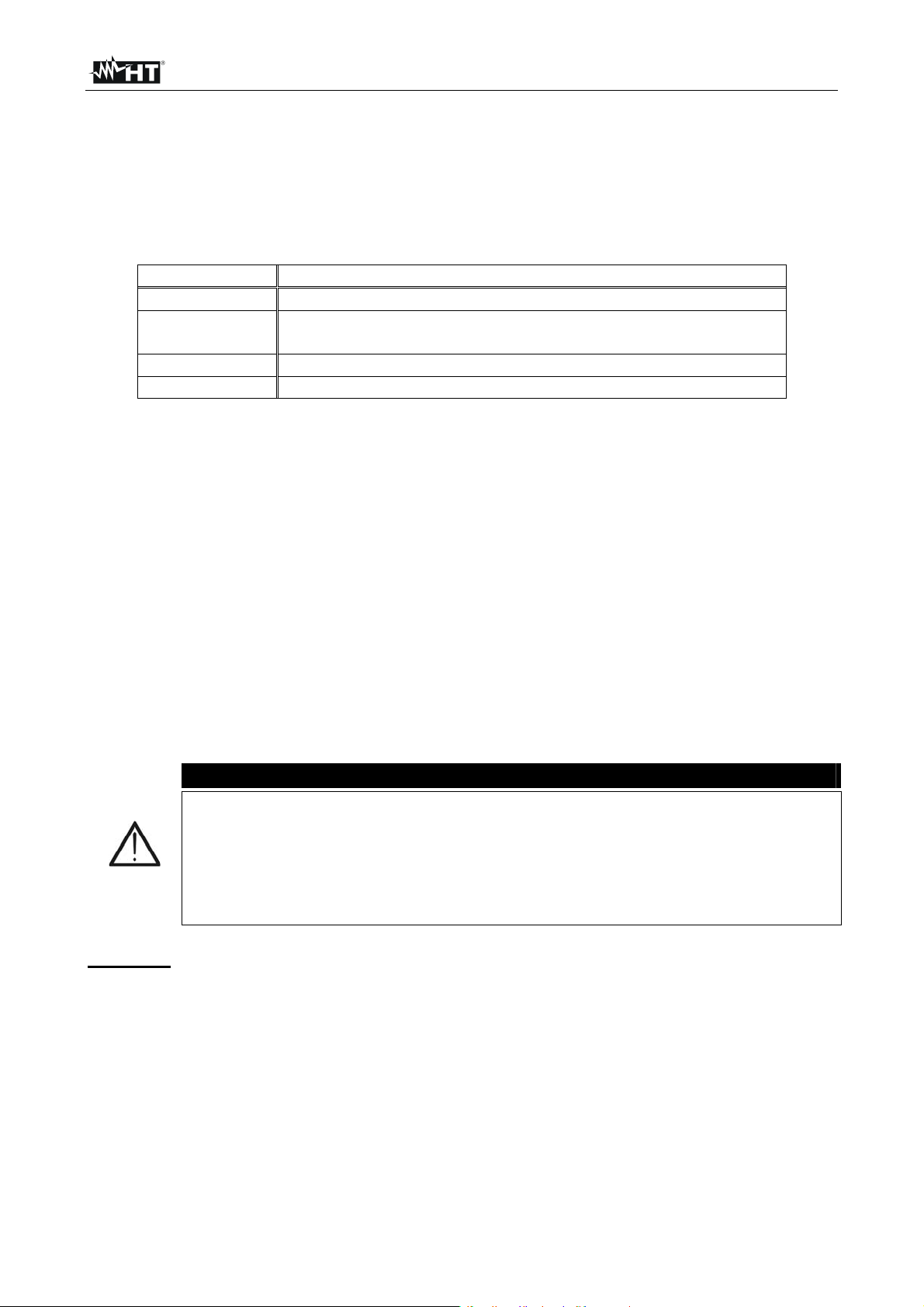
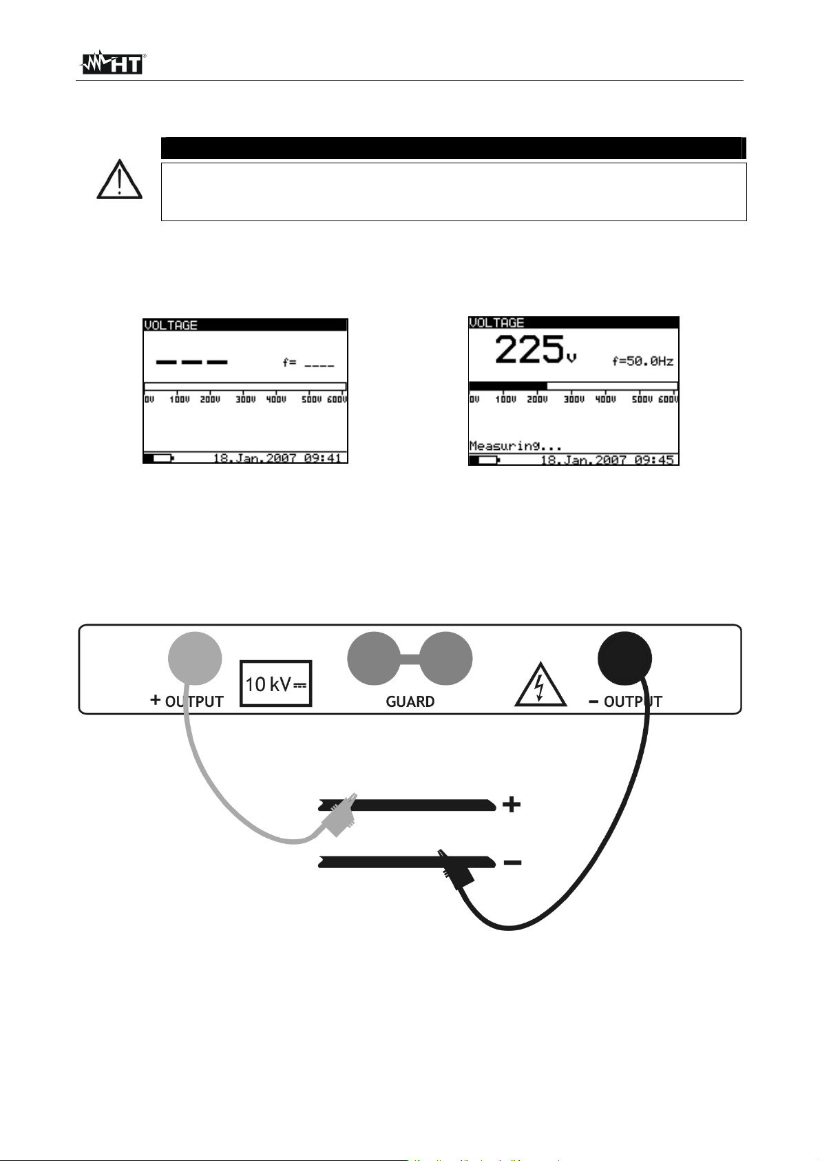
6.4 VOLTAGE MEASUREMENT
CAUTION
Maximum input for DC or AC voltage is 600V. Do not attempt to take any
voltage measurement that exceeds the limits. Exceeding the limits could
cause electrical shock and damage the instrument
1. Switch on the instrument by pressing the ON/OFF key
2. Select with arrow keys or the item “VOLTAGE” on main menu and confirm with
SELECT key. The screen of Fig. 13 is shown by the meter
Fig. 13: Initial screen of voltage measure Fig. 14: Screen of measured value
3. Connect the red part of the Test lead 1 or Test leads 2 (see § 4.2) to the +OUTPUT
input and the black part of the Test leads 2 (see § 4.2) to the –OUTPUT input
4. Connect the tip of Test lead 1 or Test leads 2 (positive) and the black cable of Test
leads 2 (negative) to the object on test respect the polarities for DC voltage
measurement (see Fig. 15)
Fig. 15: Connection of meter for voltage measurement
5. Press START/STOP key to activate the measurement in continuous mode
6. Press again the START/STOP to stop the measurement. The result of test is shown at
display (see Fig. 14)
7. For saving the result see § 7
EN - 18
Page 21
HT7052
6.5 INSULATION RESISTANCE MEASUREMENT
6.5.1 Setting of parameters
1. Switch on the instrument by pressing the ON/OFF key
2. Select with arrow keys or the item “INSULATION RESISTANCE” on main menu
and confirm with SELECT key. The screen of Fig. 16 is shown by the meter. In case of
activation of Graphic R(t) option press arrow keys or to select the graphical
screen of Fig. 17
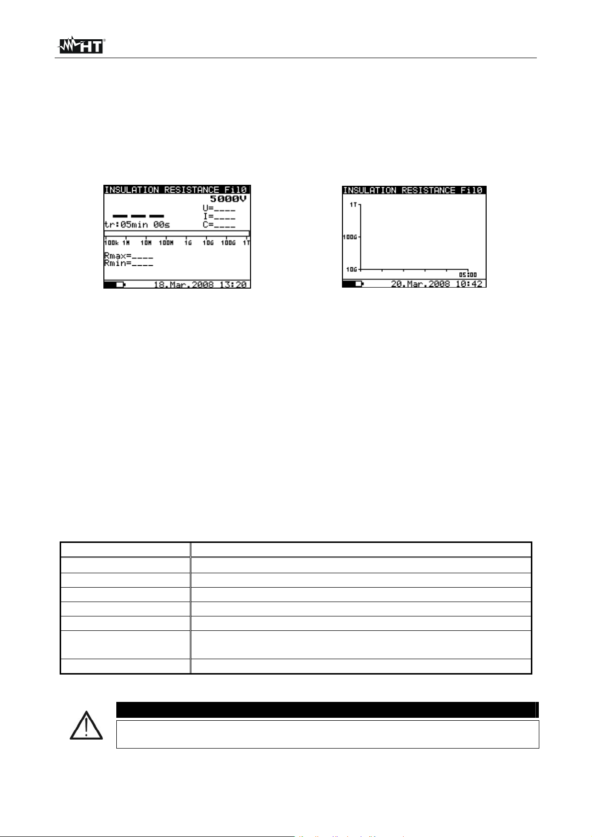
Fig. 16: Initial numerical screen Fig. 17: Initial graphical screen
3. Press again the SELECT key to enter in the setup parameters section. The screen of
Fig. 18 is shown by the meter
4. Use the arrow keys or for the selection of parameters. The herewith Table 3
shows the meaning of the measurement parameters
5. Set the values by using the arrow keys or . Press SELECT key to select possible
sub-parameters and repeat the settings
6. To activate the graphical screen the parameter Graph R(t) should be ON and the Timer
must be activated (see Fig. 18). The time duration of graphical function is
correspondent to the value of set Timer
7. The Timer value could be very long (up to 30 minutes), so the special automatic
decimation algorithm (LOG) is use to write the Graph R(t) at display (see Fig. 19)
8. The cursors of the Graph R(t) could be activated with key at the end of
measurement. The cursors of the Graph R(t) could be moved with or keys
9. Press ESC key to save the settings and back to the measurement screen or the
START/STOP key to exit from the settings menu and activate the test
Parameter Description
Unominal
Set test voltage – Range 500V10kV step 25V
Timer Duration of the measurement
Timer ON/OFF ON: timer activated, OFF timer disabled
Time 1 Time to accept and display first Rmin and Rmax results
Graph R(t) Enable/Disable Graph R(t)
R(t)
Set of minimum and maximum values of R(t) for graphical
screen
R(t) Type Set of “LIN” (linear) o “LOG” algorithm of graphical screen
Table 3: Setting of internal parameters
Timer and Time1 are independent timers. Maximum time for each of them is
30 min 60s
CAUTION
EN - 19
Page 22
HT7052
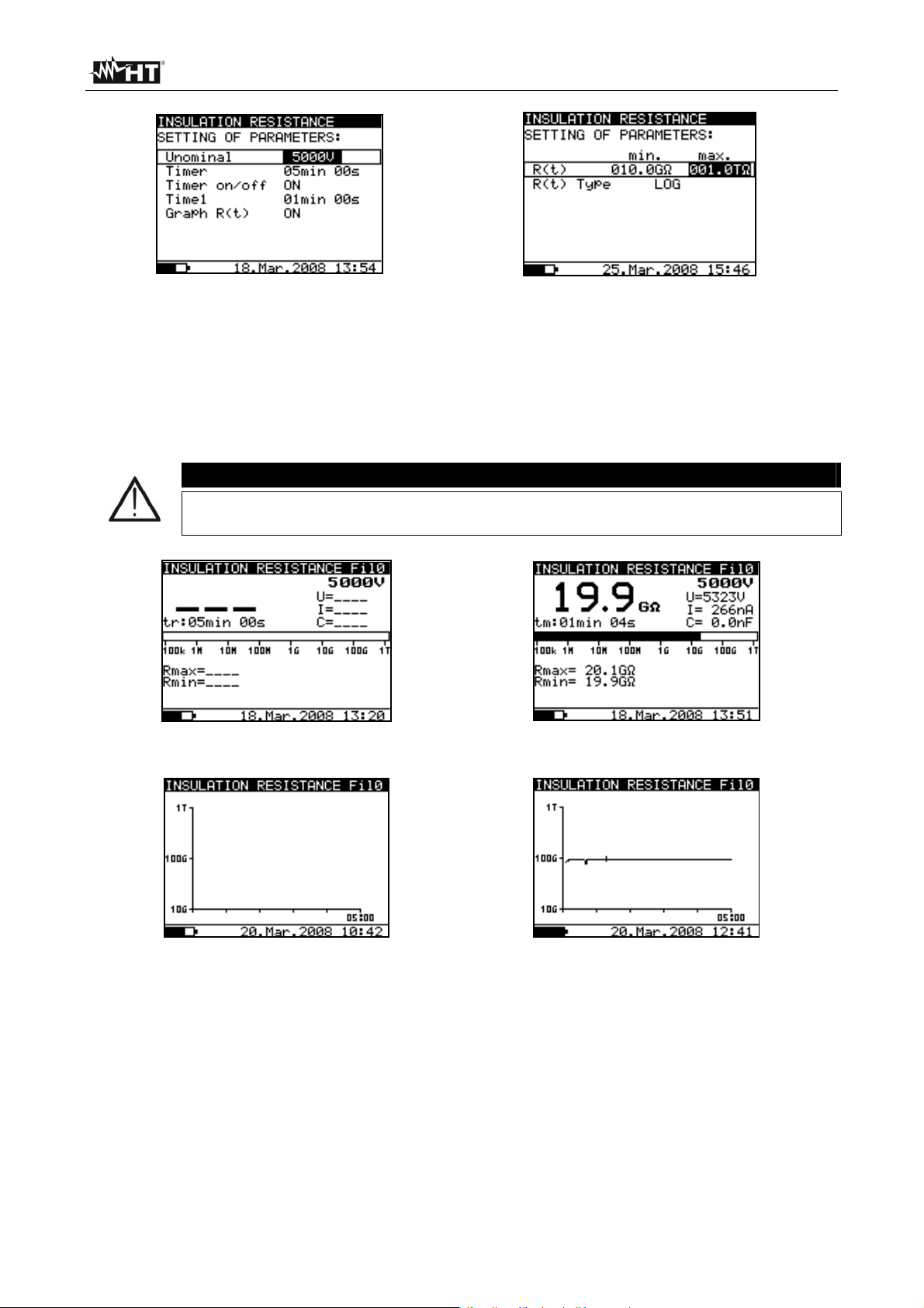
Fig. 18: Setting parameters Fig. 19: Setting of graph R(t) parameters
6.5.2 Perform the measurement
1. Switch on the instrument by pressing the ON/OFF key
2. Select with arrow keys or the item “INSULATION RESISTANCE” on main menu
and confirm with SELECT key. The screen of Fig. 20 is shown by the meter. In case of
activation of Graphic R(t) option press arrow keys or to select the graphical
screen of Fig. 22
It is not possible to switching mode of presentation when measurement
running
CAUTION
Fig. 20: Initial numerical screen Fig. 21: Numerical screen of result
Fig. 22: Initial graphical screen Fig. 23: Graphical screen of result
3. Connect the red part of the Test lead 1 or Test leads 2 (see § 4.2) to the +OUTPUT
input and the black part of the Test leads 2 (see § 4.2) to the –OUTPUT input
4. Connect the tip of Test lead 1 or Test leads 2 (positive) and the black cable of Test
leads 2 (negative) to the object on test (see Fig. 24)
EN - 20
Page 23

HT7052
Fig. 24: Connection of instrument for insulation measurement
5. Press START/STOP key to activate the measurement in continuous mode
6. Wait for a stable result at display and press again START/STOP key to stop the
measurement or wait for the end of the set Timer. The result of test is shown at display
(see Fig. 21 or Fig. 23) with meaning of items descript in Table 4
7. Wait for the object under test to discharge
8. For saving the result see § 7
Parameter at display Description
Fil0 (Fil1, Fil2, Fil3)
5000V
Filter type enabled, see the chapter 5.3. Configuration
(see § 6.3)
Set test voltage
U=5323V Applied test voltage
I=266nA Applied test current
19.9G
Result of insulation measurement
C=0.0nF Capacitance of measured object
Tm:01min 04s Timer information – test duration
Bargraph Analogue representation of result
Rmax=20.G
Rmin=19.9G
Maximum value of result (only if timer is enabled)
Minimum value of result (only if timer is enabled)
Table 4: Meaning of parameters of insulation measurement
CAUTION
If the timer is disabled then OFF is displayed instead of the timer value
During a measurement, the timer information displays the time needed to
the complete the measurement (tr) while after the completion the test
duration (tm) is displayed
A high-voltage warning symbol appears on the display during the
measurement to warn the operator of a potentially dangerous test voltage
Value of capacitance is measured during the final discharge of the test
object
EN - 21
Page 24
HT7052
6.6 DIAGNOSTIC TEST
6.6.1 Setting of parameters
1. Switch on the instrument by pressing the ON/OFF key
2. Select with arrow keys or the item “DIAGNOSTIC TEST” on main menu and
confirm with SELECT key. The screen of Fig. 25 is shown by the meter. In case of
activation of Graphic R(t) option press arrow keys or to select the graphical
screen of Fig. 26
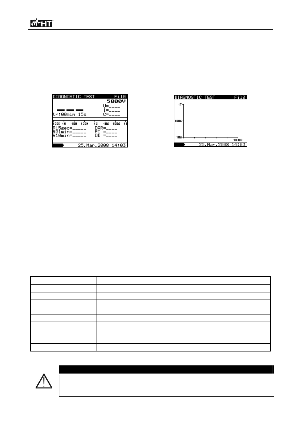
Fig. 25: Initial numerical screen Fig. 26: Initial graphical screen
3. Press again the SELECT key to enter in the setup parameters section. The screen of
Fig. 27 is shown by the meter
4. Use the arrow keys or for the selection of parameters. The herewith Table 3
shows the meaning of the measurement parameters
5. Set the values by using the arrow keys or . Press SELECT key to select possible
sub-parameters and repeat the settings
6. To activate the graphical screen the parameter Graph R(t) should be ON and the Timer
must be activated (see Fig. 27). The time duration of graphical function is
correspondent to the value of set Time3
7. The Timer value could be very long (up to 30 minutes), so the special automatic
decimation algorithm (LOG) is use to write the Graph R(t) at display (see Fig. 28)
8. The cursors of the Graph R(t) could be activated with key at the end of
measurement. The cursors of the Graph R(t) could be moved with or keys
9. Press ESC key to save the settings and back to the measurement screen or the
START/STOP key to exit from the settings menu and activate the test
Parameter Description
Unominal
Set test voltage – Range 500V10kV step 25V
Time1 Time to take R1min result
Time2 Time to take R1min result and calculate DAR
Time3 Time to take R3min result and calculate PI
DD ON/OFF ON: DD enabled, OFF: DD disabled
Graph R(t) Enable/Disable Graph R(t)
R(t)
Set of minimum and maximum values of R(t) for graphical
screen
R(t) Type Set of “LIN” (linear) o “LOG” algorithm of graphical screen
Table 5: Setting of internal parameters
CAUTION
Time1 Time2 Time3 are timers with the same start point. The value of
each presents the duration from the start of the measurement. The maximum
time is 30 min
EN - 22
Page 25
HT7052
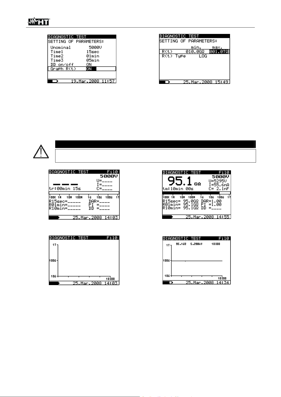
Fig. 27: Setting parameters Fig. 28: Setting of graph R(t) parameters
6.6.2 Perform the measurement
1. Switch on the instrument by pressing the ON/OFF key
2. Select with arrow keys or the item “DIAGNOSTIC TEST” on main menu and
confirm with SELECT key. The screen of Fig. 29 is shown by the meter. In case of
activation of Graphic R(t) option press arrow keys or to select the graphical
screen of Fig. 31
It is not possible to switching mode of presentation when measurement
running
CAUTION
Fig. 29: Initial numerical screen Fig. 30: Numerical screen of result
Fig. 31: Initial graphical screen Fig. 32: Graphical screen of result
3. Connect the red part of the Test lead 1 or Test leads 2 (see § 4.2) to the +OUTPUT
input and the black part of the Test leads 2 (see § 4.2) to the –OUTPUT input. In case
of use of GUARD terminals (see § 6.2) connect also the green cables to the “GUARD”
input (see Fig. 33)
4. Connect the tip of Test lead 1 or Test leads 2 (positive) and the black cable of Test
leads 2 (negative) to the object on test (see Fig. 33)
EN - 23
Page 26
HT7052
Fig. 33: Connection of instrument for diagnostic test
5. Press START/STOP key to activate the insulation measurement
6. Wait for the end of the set Timers. The result of test is shown at display (see Fig. 30 or
Fig. 32) with meaning of items descript in Table 6
7. Wait for the object under test to discharge
8. For saving the result see § 7
Parameter at display Description
Fil0 (Fil1, Fil2, Fil3) Filter type enabled on test (see § 6.3)
5000V
Set test voltage – step 25 V
U=5295V Applied test voltage
I=55.6nA Applied test current
95.1G
Result of insulation measurement
C=2.1nF Capacitance of measured object
Bargraph Analogue representation of Riso result
R15sec=95.0G
R01min=95.1G
R10min=95.1G
Resistance value measured after set time 1
Resistance value measured after set time 2
Resistance value measured after set time 3
DAR=1.00 DAR as ratio of R1min / R15s
PI=1.00 PI as ratio of R10min/R1min
DD= DD result
Table 6: Meaning of parameters of diagnostic test
CAUTION
A high-voltage warning symbol appears on the display during the
measurement to warn the operator of a potentially dangerous test voltage
The value of the capacitance is measured during the final discharge of the
test object
If enabled, the instrument measures Dielectric Discharge (DD) when the
capacitance is in the range 5nF 50F
EN - 24
Page 27
HT7052
6.7 INSULATION RESISTANCE WITH STEP VOLTAGE TEST
6.7.1 Setting of parameters
1. Switch on the instrument by pressing the ON/OFF key
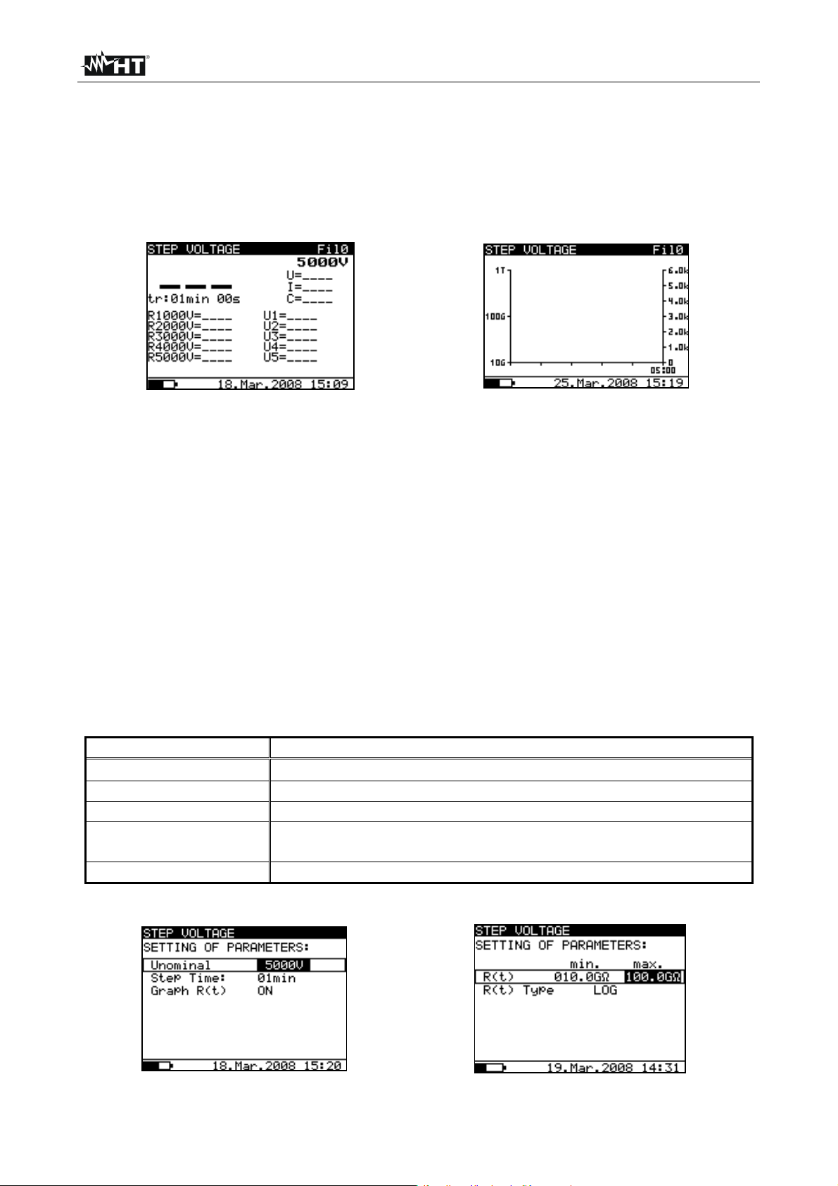
2. Select with arrow keys or the item “STEP VOLTAGE” on main menu and confirm
with SELECT key. The screen of Fig. 34 is shown by the meter. In case of activation of
Graphic R(t) option press arrow keys or to select the graphical screen of Fig. 35
Fig. 34: Initial numerical screen Fig. 35: Initial graphical screen
3. Press again the SELECT key to enter in the setup parameters section. The screen of
Fig. 36 is shown by the meter
4. Use the arrow keys or for the selection of parameters. The herewith Table 7
shows the meaning of the measurement parameters
5. Set the values by using the arrow keys or . Press SELECT key to select possible
sub-parameters and repeat the settings
6. To activate the graphical screen the parameter Graph R(t) should be ON and the Timer
must be activated (see Fig. 36). The time duration of graphical function is
correspondent to the value of Step Timer multiplied by 5
7. The Timer value could be very long (up to 150 minutes), so the special automatic
decimation algorithm (LOG) is use to write the Graph R(t) at display (see Fig. 37)
8. The cursors of the Graph R(t) could be activated with key at the end of
measurement. The cursors of the Graph R(t) could be moved with or keys
9. Press ESC key to save the settings and back to the measurement screen or the
START/STOP key to exit from the settings menu and activate the test
Parameter Description
Unominal
Step time Duration of measurement per step
Graph R(t) Enable/Disable Graph R(t)
R(t)
R(t) Type Set of “LIN” (linear) o “LOG” algorithm of graphical screen
Set test voltage – Range 2kV10kV step 125V
Set of minimum and maximum values of R(t) for graphical
screen
Table 7: Setting of internal parameters
Fig. 36: Setting parameters Fig. 37: Setting of graph R(t) parameters
EN - 25
Page 28
HT7052
6.7.2 Perform the measurement
1. Switch on the instrument by pressing the ON/OFF key
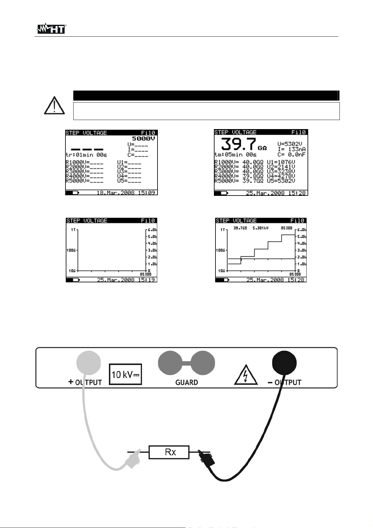
2. Select with arrow keys or the item “STEP VOLTAGE” on main menu and confirm
with SELECT key. The screen of Fig. 38 is shown by the meter. In case of activation of
Graphic R(t) option press arrow keys or to select the graphical screen of Fig. 40
It is not possible to switching mode of presentation when measurement
running
CAUTION
Fig. 38: Initial numerical screen Fig. 39: Numerical screen of result
Fig. 40: Initial graphical screen Fig. 41: Graphical screen of result
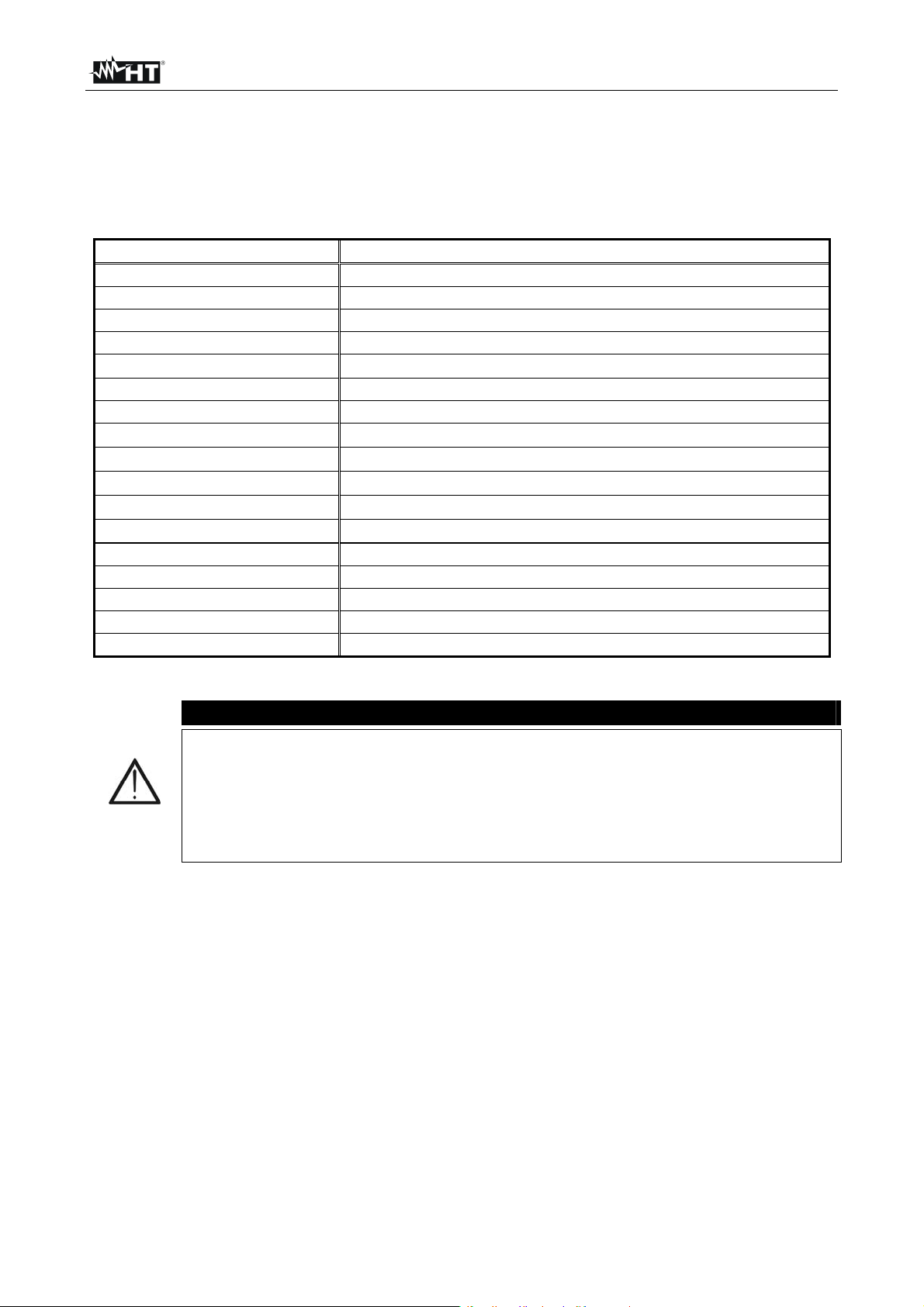
3. Connect the red part of the Test lead 1 or Test leads 2 (see § 4.2) to the +OUTPUT
input and the black part of the Test leads 2 (see § 4.2) to the –OUTPUT input
4. Connect the tip of Test lead 1 or Test leads 2 (positive) and the black cable of Test
leads 2 (negative) to the object on test (see Fig. 24)
Fig. 42: Connection of instrument for insulation measurement
EN - 26
Page 29
HT7052
d
t
d
d
5. Press START/STOP key to activate the insulation measurement
6. Wait for the end of the set Timers. The result of test is shown at display (see Fig. 39 or
Fig. 41) with meaning of items descript in Table 8
7. Wait for the object under test to discharge
8. For saving the result see § 7
Parameter at display Description
Fil0 (Fil1, Fil2, Fil3) Filter type enabled (see § 6.3)
5000V
Set test voltage – step 125 V
U=5302V Applied test voltage
I=133nA Applied test current
39.7G
Result of insulation measurement
C=0.0nF Capacitance of measured object
Tm:05min 00s Actual test duration
st
R1000V=40.0G
R2000V=40.0G
R3000V=40.0G
R4000V=39.8G
R5000V=39.7G
U1=1076V 1
U2=2141V 2
U3=3238V 3
Last result of 1
Last result of 2nd step
Last result of 3
Last result of 4th step
Last result of 5th step
s
step voltage
n
step voltage
r
step voltage
step
r
step
U4=4278V 4th step voltage
U5=5302V 5th step voltage
Table 8: Meaning of parameters of insulation measurement with step voltage
CAUTION
Timer information is displayed from the start of the measurement until the
completion of each step measurement
A high-voltage warning symbol appears on the display during the
measurement to warn the operator of a potentially dangerous test voltage
The value of the capacitance is measured during the final discharge of the
test object
EN - 27
Page 30
HT7052
6.8 WITHSTANDING VOLTAGE TEST
6.8.1 Setting of parameters
1. Switch on the instrument by pressing the ON/OFF key
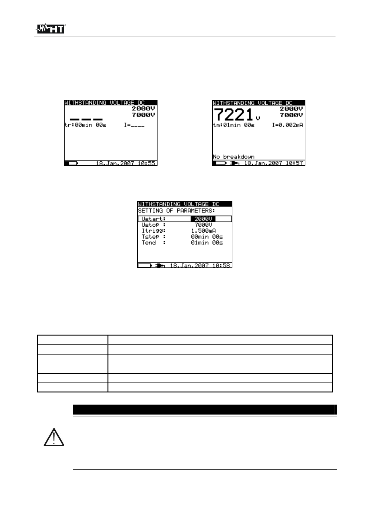
2. Select with arrow keys or the item “WITHSTANDING VOLTAGE DC” on main
menu and confirm with SELECT key. The screen of Fig. 43 is shown by the meter
Fig. 43: Initial screen withstanding test Fig. 44: Final screen withstanding test
3. Press again the SELECT key to enter in the setup parameters section. The screen of
Fig. 45 is shown by the meter
Fig. 45: Setting parameters
4. Use the arrow keys or for the selection of parameters. The herewith Table 9
shows the meaning of the measurement parameters
5. Set the values by using the arrow keys or . Press SELECT key to select possible
sub-parameters and repeat the settings
6. Press ESC key to save the settings and back to the measurement screen or the
START/STOP key to exit from the settings menu and activate the test
Parameter Description
Ustart
Ustop
Itrigg
Start test voltage – Range 500V10kV step 25V
Stop test voltage – Range 500V10kV step 25V
Set trigger leakage current – Range 0.001mA 5mA step 10A
Tstep Duration of test voltage per one step
Tend Duration of constant test voltage after reaching stop value
Table 9: Setting of internal parameters
CAUTION
Tstep and Tend are independent timers. The maximum time for each timer
is 30 min 60 s. Tend begins after the completion of the ramp period. Ramp
period can be calculated from:
Ttot-ramp Tstep * [(Ustop-Ustart) / 25V]
If Tstep is set to 00min 00s, then the ramp voltage increases by
approximately 25 V every 2s
EN - 28
Page 31

HT7052
6.8.2 Perform the measurement
1. Switch on the instrument by pressing the ON/OFF key
2. Select with arrow keys or the item “WITHSTANDING VOLTAGE DC” on main
menu and confirm with SELECT key. The screen of Fig. 43 is shown by the meter
3. Connect the red part of the Test lead 1 or Test leads 2 (see § 4.2) to the +OUTPUT
input and the black part of the Test leads 2 (see § 4.2) to the –OUTPUT input
4. Connect the tip of Test lead 1 or Test leads 2 (positive) and the black cable of Test
leads 2 (negative) to the object on test (see Fig. 46)
Fig. 46: Connection of instrument for withstanding test
5. Press START/STOP key to activate the measurement
6. Wait until the set timers run out or until breakdown occurs. The result of test is shown
at display (see Fig. 44) with meaning of items descript in Table 10
7. Wait for the object under test to discharge
8. For saving the result see § 7
Parameter at display Description
2000V
7000V
7221V
Start test voltage
Stop test voltage
Applied test voltage
I=0.002mA Measured leakage current
Tm:01min 00s Timer information
Table 10: Meaning of parameters of withstanding test
CAUTION
Breakdown is detected when the measured current reaches or exceeds the
set current level Itrigg (see § 6.8.1)
The timer shows the time needed to complete each step during the
measurement and it shows the total measurement period after the
completion of the measurement
A high-voltage warning symbol appears on the display during the
measurement to warn the operator of a potentially dangerous test voltage
EN - 29
Page 32

HT7052
7 MANAGEMENT OF MEMORY DATA
7.1 SAVING, RECALL AND CLEAR MEASUREMENT RESULTS
SAVING DATA
1. With measurement result displayed press MEM key. The screen of Fig. 47 is shown by
the instrument
SAVE CLR RCL nnnn
Fig. 47: Saving data
2. Use the arrow keys or and select the “MEM” option. The “nnnn” number shows
the memory location where the data will be saved
3. Press again MEM key to confirm the operation. A double acoustic signal is given by the
instrument
RECALL SAVED DATA
1. Press MEM key, use the arrow keys or to select the “RCL” option and confirm
again with MEM key. The last saved data is shown at display
2. Use the arrow keys or to select and display the saved data correspondent to the
previous memory locations
3. The recalled data with “G” indication means the presence of a graphical screen more
than the numerical. Press SELECT key to display the graphical screen and ESC to
return to the numerical one
4. Press ESC key to exit from the function and return in measurement mode
CLEAR RESULT
1. For clear all internal memory select the “Memory clear” parameter (see § 5.2), press
SELECT key and confirm with MEM key
2. Press ESC key to exit from the function
3. For clear the last saved result press MEM key, use the arrow keys or to select the
“CLR” option and confirm again with MEM. A double acoustic signal is given by the
instrument to confirm the operation
EN - 30
Page 33

HT7052
8 CONNECTION OF THE INSTRUMENT TO PC
The saved data can be transferred to PC by using the TeraView dedicated software
included with instrument
TeraView software permits the herewith operations:
Download data from meter
Define customized settings on the final report
Analyze the results of measurements in numerical and graphical screens
Print the final report
Export the data in text (TXT) format file
MINIMUM SYSTEM REQUIREMENTS
Pentium III – 500MHz
512 MB RAM
100 MB free space on HD
CD-ROM reader
USB/serial port
Video resolution 800x600
Windows systems: Win2k/XP/Vista/Win7 32 bit and 64 bit platforms
8.1 INSTALLATION OF SOFTWARE AND INITIAL CONFIGURATIONS (WIN XP)
1. Close all the open application on the PC
2. Insert the supplied CD-ROM in the PC reader
3. Launch the “TeraView.exe” file included on CD-ROM and follow the steps to correctly
install the TeraView software
4. Switch on the instrument, set the USB mode (see § 5.2) and connect it to the PC by
using the supplied USB cable
5. Read the “Instal_USB_neutral.pdf” file inside the “Handbook” folder for the installation
of USB driver on the PC
6. Launch the TeraView software
7. Select the command “Config Password…”, type the serial number of meter and the
password (which is indicated on the CD-ROM label) and confirm with “Add” (see Fig.
48)
Fig. 48: Insertion of initial password
EN - 31
Page 34
HT7052
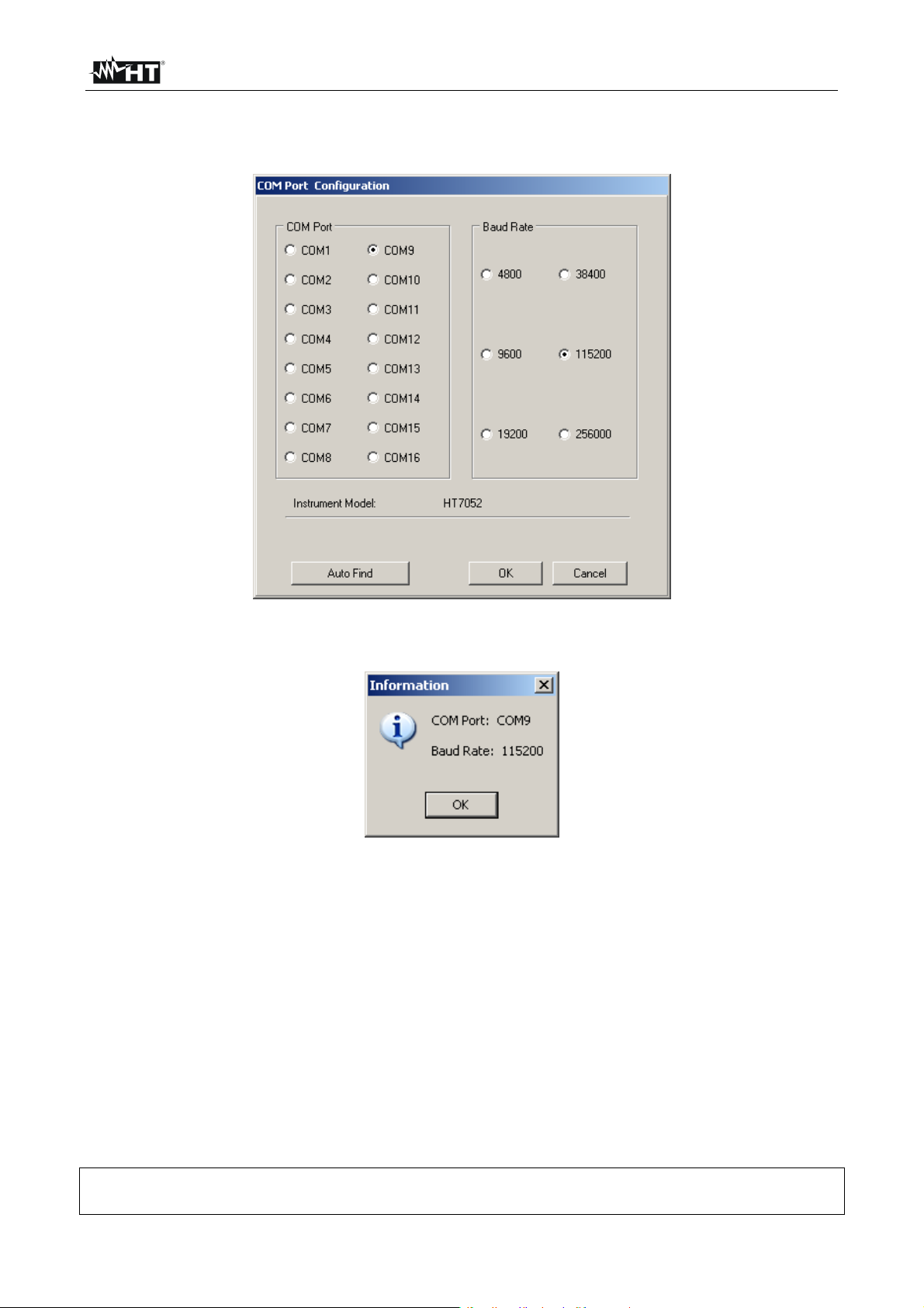
8. Select the “Config COM Port…” command and click on the “AutoFind” button to
start the automatic detection of the instrument (see Fig. 49)
Fig. 49: Connection of the instrument to PC
9. The herewith message means a correct detection of meter by the PC
Fig. 50: Correct detection of instrument
10. In case of failed detection of the meter by the PC it should be necessary to re-configure
the “virtual” COM serial port associated the USB driver previously installed. The
TeraView program can detect automatically serial ports from the COM1 to the COM16.
Follow the herewith steps to modify the COM associated to USB driver:
Right click of mouse on the “My computer” icon on the PC desktop and selection of
“Properties” item
“Hardware” folder “Device Manager” “Ports (COM & LPT)
Move on the “USB CDC Serial Port Emulation (COMxx)” item right click
“Properties”
Select “Port Settings” “Advanced…”
In the COM Port Number list select a “COMxx” among COM1 and COM16
Confirm all operations, come back to software TeraView and repeat the AutoFind
For any information about the use of TeraView software refer to the help on line of
the same program
EN - 32
Page 35

HT7052
9 MAINTENANCE
9.1 GENERAL INFORMATION
The instrument You purchased is a precision instrument. During use and storage, carefully
observe the recommendations listed in this manual in order to prevent possible damage or
dangers during use. Do not use the instrument in environments with high humidity levels or
at high temperatures. Do not directly expose to sunlight. Always turn off the instrument
after use. Never remove the front panel of the instrument. The instrument don’t need any
particular maintenance
9.2 REPLACEMENT AND CHARGING BATTERIES
The instrument is power-supplied through internal rechargeable batteries which are
recharged from the mains by means of a battery charger integrated in the instrument itself.
The symbol “ “ illuminated in the left bottom part indicates that the batteries are flat
and must be recharged
Connect the instrument to the mains power supply for 20 hours to fully
charge batteries. (typical charging current is 600mA). When you charge the
batteries for the first time, it normally takes about 3 charge and discharge
cycles for the batteries to regain full capacity
The operator does not need to disconnect the instrument from mains
supply after the full recharging period. The instrument can be connected
permanently
The instrument will only work when rechargeable batteries are inside the
In case of batteries replacement follow the herewith steps:
instrument
Nominal power supply voltage is 7.2 V DC. Use only six NiMH cells with
size equivalent to IEC LR20 (diameter = 33 mm, height = 58 mm)
1. Turn the power off and disconnect any measurement accessories or mains supply
cable connected to the instrument before opening the battery cover to avoid electric
shock
2. Remove the two screws (see Fig. 1 – Part 15) and open the battery cover
3. Replace all the six batteries with others of the same type respecting the indicated
polarity
4. Restore the battery cover
5. Use the appropriate battery disposal methods for your area
CAUTION
CAUTION
9.3 CLEANING THE INSTRUMENT
To clean the instrument, use a soft dry cloth. Never use humid cloths, solvents, water, etc
9.4 END OF LIFE
Warning: the reported symbol indicates that the appliance, the batteries and its
accessories must be disposed of separately and treated correctly
EN - 33
Page 36

HT7052
10 TECHNICAL SPECIFICATIONS
Accuracy is given as [%rdg + (number of dgt) * resolution] at reference indicated in § 0
INSULATION RESISTANCE MEASUREMENT
Measurement range Resolution Accuracy
120k 999k 1k
1.00M 9.99M 0.01M
10.0M 99.9M 0.1M
100M 999M 1M
1.00G 9.99G 0.01G
10.0G 99.9G 0.1G
100G 999G 1G
1.00T 10.00T 0.01T (15.0 rdg + 3 dgt)
FS value of insulation resistance is defined as: RFS = 1G * Utest [V]
Nominal test voltage: 500 10kV DC
Current capability of test generator: > 1mA
Short-circuit test current: 5mA 10%
Automatic discharge of tested object: yes
Measurement range test voltage Resolution Accuracy
0 9999V
10kV
Nominal test voltage: 500 10kV DC programmable in step of 25V
Accuracy of test voltage: -0 / +10% + 20V
Output power: 10W max
1V
0.1kV
Measurement range test current Resolution Accuracy
0.00 9.99nA
10.0 99.9nA
100 999nA
0.01nA
0.1nA
1nA
1.00 9.99A 0.01A
10.0 9.99A 0.1A
100 999A 1A
1.00 5.50mA
0.01mA
Noise current rejection (resistive load)
Filter option Maximum current @ 50Hz (mA rms)
Fil0 1.5
Fil1 2.5
Fil2 4.5
Fil3 5
Diagram Test voltage – Resistance
(5.0rdg + 3dgt)
(3.0 rdg + 3V)
3.0 rdg
(5.0 rdg + 0.05nA)
12
10
8
6
[ kV ]
4
2
0
0,1 1 10 100
[ M ]
Utest=10kV Utest=5kV
EN - 34
Page 37

HT7052
DAR, PI, DD MEASUREMENT
Measurement range Resolution Accuracy
0.01 9.99
10.0 100.0
Capacitance range for DD test: 5nF 50F
0.01
0.1
(5.0 rdg + 2 dgt)
5.0 dgt
INSULATION MEASUREMENT WITH STEP VOLTAGE
Measurement range test voltage Resolution Accuracy
2000 9999V
10kV
Nominal test voltage: 2000 10kV DC programmable in steps of 125V
Accuracy of test voltage: -0 / +10% + 20V
1V
0.1kV
(3.0 rdg + 3V)
3.0 rdg
WITHSTANDING VOLATGE DC
Measurement range test voltage Resolution Accuracy
500 9999V
10kV
1V
0.1kV
(3.0 rdg + 3V)
3.0 rdg
Measurement range leakage current Resolution Accuracy
0.000 0.009mA
0.01 5.50mA
Nominal test voltage: 500 10kV DC programmable in steps of 25V
Accuracy of test voltage: -0 / +10% + 20V
0.001mA
0.01mA
(3.0 rdg + 3 dgt)
3.0 rdg
AC or DC VOLTAGE
Measurement range Resolution Accuracy
0 600V
Input impedance: 3M 10%
1V
(3.0 rdg + 4V)
Voltage frequency Resolution Accuracy
0 e 45.0 65.0Hz
Frequency within 0 and 45Hz: displayed < 45Hz
Frequency > 65Hz: displayed > 65Hz
0.1Hz
0.2Hz
CAPACITANCE
Measurement range Resolution Accuracy
0.0 99.9nF
100 999nF
0.1nF
1nF
(5.0 rdg + 2 dgt)
1.00 50.0F 0.01F
Full-scale value of capacitance is defined as: CFS = 10F * Utest [kV]
10.1 SAFETY STANDARDS
Instrument safety: IEC/EN61010-1, IEC/EN61557-2
Measuring accessory safety: IEC/EN61010-031
Insulation: double insulation
Protection: IP44 (closed case)
Polluting level: 2
Overvoltage category: CAT IV 600V (to earth), max 600V between inputs
Maximum altitude: 2000m (6561ft)
EN - 35
Page 38

HT7052
10.2 GENERAL CHARACTERISTICS
Mechanical characteristics
Dimensions (LxWxH): 360 x 330 x 160mm; 14 x 13 x 6in
Weight (with batteries): 5.5kg; 11lv
Power supply
External supply: 90-260V AC, 45-65Hz, 60VA
Internal supply: 6x1.2V rechargeable NiMH battery IEC LR20
Low battery indication: symbol “ “ at display
Battery life: approx 4 hours (continuous test on 10kV)
Display
Characteristics: LCD, dot matrix, with backlight (160x116pxl)
Memory
Characteristics: 1000 memory locations
Discharging
Characteristics: each time after the end of test; resistance 425
10%
Connection to PC
RS-232 serial interface: optoinsulated (2400,4800,9600,19200 baud, 1, N)
USB interface: type B standard, 115000 baud
10.3 ENVIRONMENT
Reference temperature: 10°C ÷ 30°C; 50°F ÷ 86°F
Reference humidity: 40%RH ÷ 60%RH
Operating temperature: -10°C ÷ 50°C; 14°F ÷ 122°F
Operating humidity: <90%HR
Storage temperature: -20°C ÷ 70°C; -4°F ÷ 158°F
Storage humidity: <90%HR
This instrument complies with the requirements of European Directive on low
voltage 2006/95/EC (LVD) and of Directive EMC 2004/108/EC
10.4 ACCESSORIES
N 1 Test lead red, protection 10kV, 2m
N 2 Test leads (red/black), basic protection 10kV (double protection 5kV), 2m
N 2 Alligator clips (red/black), basic protection 10kV (double protection 5kV)
N 1 Guard test lead green
N 1 Guard alligator clip green
N 1 Mains cord
N 1 USB cable
N 1 RS-232 cable
“TeraView” software on CD-ROM
6x1.2V rechargeable batteries NiMH type IEC LR20
User manual
ISO9000 calibration certificate
EN - 36
Page 39

HT7052
11 SERVICE
11.1 WARRANTY CONDITIONS
This instrument is warranted against any material or manufacturing defect, in compliance
with the general sales conditions. During the warranty period, defective parts may be
replaced. However, the manufacturer reserves the right to repair or replace the product
Should the instrument be returned to the After-sales Service or to a Dealer, transport will
be at the Customer's charge. However, shipment will be agreed in advance
A report will always be enclosed to a shipment, stating the reasons for the product’s return
Only use original packaging for shipment; any damage due to the use of non-original
packaging material will be charged to the Customer
The manufacturer declines any responsibility for injury to people or damage to property
The warranty shall not apply in the following cases:
Repair and/or replacement of accessories and battery (not covered by warranty)
Repairs that may become necessary as a consequence of an incorrect use of the
instrument or due to its use together with non-compatible appliances
Repairs that may become necessary as a consequence of improper packaging
Repairs which may become necessary as a consequence of interventions performed
by unauthorized personnel
Modifications to the instrument performed without the manufacturer’s explicit
authorization
Use not provided for in the instrument’s specifications or in the instruction manual
The content of this manual cannot be reproduced in any form without the manufacturer’s
authorization.
Our products are patented and our trademarks are registered. The manufacturer
reserves the right to make changes in the specifications and prices if this is due to
improvements in technology
11.2 SERVICE
If the instrument does not operate properly, before contacting the After-sales Service,
please check the conditions of battery and cables and replace them, if necessary
Should the instrument still operate improperly, check that the product is operated
according to the instructions given in this manual
Should the instrument be returned to the After-sales Service or to a Dealer, transport will
be at the Customer's charge. However, shipment will be agreed in advance
A report will always be enclosed to a shipment, stating the reasons for the product’s return
Only use original packaging for shipment; any damage due to the use of non-original
packaging material will be charged to the Customer
EN - 37
Page 40

Page 41

ESPAÑOL
Manual de Instrucciones
Copyright HT ITALIA 2013 Versión ES 2.00 - 02/01/2013
Page 42

Page 43

HT7052
Indice:
1 PRECAUCIONES Y MEDIDAS DE SEGURIDAD ............................................................... 2
1.1 Instrucciones preliminares .................................................................................................................... 2
1.2 Durante el uso ...................................................................................................................................... 3
1.3 Después del uso ................................................................................................................................... 3
1.4 Definición de categoría de medida (sobretensión) ............................................................................... 3
2 DESCRIPCIONES GENERALES ......................................................................................... 4
2.1 Funcionalidad del instrumento .............................................................................................................. 4
3 PREPARACIÓN PARA EL USO .......................................................................................... 5
3.1 Controles iniciales................................................................................................................................. 5
3.2 Alimentación del instrumento ............................................................................................................... 5
3.3 Calibración ............................................................................................................................................ 5
3.4 Almacienamiento .................................................................................................................................. 5
4 NOMENCLATURA ............................................................................................................... 6
4.1 Descripción del instrumento ................................................................................................................. 6
4.2 Utilización de las puntas de prueba ...................................................................................................... 7
5 OPERACIONES INICIALES................................................................................................. 8
5.1 Condiciones del encendido .................................................................................................................. 8
5.1.1 Alimentación del instrumento ..................................................................................................... 8
5.1.2 Uso de la Retroiluminación ........................................................................................................ 8
5.1.3 Autocalibración ........................................................................................................................... 8
5.2 Configuración y Setup de los parámetros de sistema .......................................................................... 9
6 EJECUCIÓN DE LAS MEDIDAS ....................................................................................... 10
6.1 Teoría sobre la medida de la resistencia de aislamiento ................................................................... 10
6.1.1 Prueba en función del tiempo – Prueba diagnóstica ................................................................ 12
6.1.2 Prueba de rigidez dieléctrica .................................................................................................... 15
6.2 TErminal de guarda ............................................................................................................................ 16
6.3 Uso de los filtros internos ................................................................................................................... 17
6.3.1 Significado del filtrado interno .................................................................................................. 17
6.4 Medida de tensión .............................................................................................................................. 18
6.5 Medida de la resistencia de aislamiento ............................................................................................ 19
6.5.1 Configuración de los parámetros ............................................................................................. 19
6.5.2 Ejecución de la medida ............................................................................................................ 20
6.6 Prueba diagnósticas sobre la calidad de los materiales .................................................................... 22
6.6.1 Configuración de los parámetros ............................................................................................. 22
6.6.2 Ejecución de la medida ............................................................................................................ 23
6.7 Medida de aislamiento con rampa de tensión .................................................................................... 25
6.7.1 Configuración de los parámetros ............................................................................................. 25
6.7.2 Ejecución de la medida ............................................................................................................ 26
6.8 Prueba de rigidez dieléctrica en CC ................................................................................................... 28
6.8.1 Configuración de los parámetros ............................................................................................. 28
6.8.2 Ejecución de la medida ............................................................................................................ 29
7 OPERACIONES CON MEMORIA ...................................................................................... 30
7.1 Guardado, rellamado sobre el visualizador y cancelación de los resultados..................................... 30
8 CONEXIÓN DEL INSTRUMENTO AL PC ......................................................................... 31
8.1 Instalación del programma de gestión y configuración inicial (Win XP) ............................................. 31
9 MANTENIMIENTO.............................................................................................................. 33
9.1 Generalidades .................................................................................................................................... 33
9.2 Sustitución y recarga de las baterías ................................................................................................. 33
9.3 Limpieza del instrumento .................................................................................................................... 33
9.4 Fin de vida .......................................................................................................................................... 33
10 ESPECIFICACIONES TÉCNICAS ..................................................................................... 34
10.1 Normas de seguridad ......................................................................................................................... 35
10.2 Características generales ................................................................................................................... 36
10.3 Ambiente ............................................................................................................................................. 36
10.4 Accesorios .......................................................................................................................................... 36
11 ASISTENCIA ...................................................................................................................... 37
11.1 Condiciones de garantía ..................................................................................................................... 37
11.2 Asistencia ........................................................................................................................................... 37
ES - 1
Page 44

HT7052
1 PRECAUCIONES Y MEDIDAS DE SEGURIDAD
El instrumento ha sido proyectado en conformidad a las directivas IEC/EN61557-2 y
IEC/EN61010-1relativas a los instrumentos de medida electrónicos
Para la seguridad del operador y para evitar dañar al instrumento, siga los
procedimientos descritos en el presente manual y lea con particular atención
todas las notas precedidas por el símbolo
Antes y durante la ejecución de las medidas atenergase escrupulosamente a las
siguientes indicaciones:
No efectúe medidas en ambientes húmedos, con presencia de gas o materiales
explosivos, combustibles o en ambientes polvorientos
Evite el contacto con el circuito en examen si se está efectuando medidas, con partes
metálicas expuestas, con terminales de medida inutilizados, circuitos, etc
No efectúe ninguna medida si existe alguna anomalía en el instrumento como
deformación, roturas, pérdidas de sustancias, ausencias de visualización sobre el
visualizador, etc
Preste particular atención cuando se esté efectuando medidas de tensión superiores a
25V en ambientes especiales (obras, piscinas, etc) y 50V en ambientes ordinarios en
cuanto se encuentre en presencia de riesgo de choques eléctricos
En el presente manual y sobre el instrumento son utilizados los siguientes símbolos:
ATENCIÓN: aténgase a las instrucciones mostradas en el manual. Un uso
impropio puede causar daños al instrumento y situaciones peligrosas para el
usuario
ATENCIÓN
Peligro tensiones peligrosas: riesgo de shock eléctrico
Tensión o corriente CC
Instrumento con doble aislamiento
1.1 INSTRUCCIONES PRELIMINARES
Este instrumento ha sido fabricado para un uso en ambiente con nivel de polución 2
Puede ser utilizado para la verificación sobre instalaciones eléctricas industriales hasta
CAT IV 600V respecto a tierra con tensión máxima 600V entre las entradas
Siga las normas de seguridad orientadas a proteger al usuario de corrientes peligrosas
y proteger el instrumento contra un uso erróneo
Utilice el instrumento posicionando solo en superficies horizontales planas al suelo
Sólo los accesorios incluidos con el equipo garantizan las normas de seguridad. Deben
estar en buenas condiciones y si fuese necesario, sustituirlos por los modelos
originales
No efectúe medidas sobre circuitos que superen los límites de corriente y tensión
especificados
No efectúe medidas en condiciones ambientales fuera de las limitaciones indicadas en
el presente manual
Antes de conectar las puntas de prueba al circuito en examen, controle que el
conmutador esté en posición correcta
Asegúrese que el objeto en prueba esté desconectado a la red antes de activar la
medida de la resistencia de aislamiento
ES - 2
Page 45

HT7052
1.2 DURANTE EL USO
Le rogamos que lea atentamente las recomendaciones y las instrucciones siguientes:
ATENCIÓN
La falta de observación de las advertencias y/o instrucciones pueden dañar el
instrumento y/o sus componentes o ser fuente de peligro para el usuario. Si
durante el uso aparece el símbolo de batería agotada inserte el cable de
alimentación para iniciar la recarga de la batería. Durante la recarga de la
batería es posible efectuar mediciones
Antes de cambiar la función desconecte las puntas de medida del circuito en examen
Cuando el instrumento está conectado al circuito en examen no toque nunca cualquier
terminal inutilizado
Evite la medida de resistencia en presencia de tensión externa; aunque el instrumento
está protegido una tensión excesiva podría dañarlo
En caso de medida sobre un objeto con elevada capacidad interna (prueba sobre cables
largos, etc.), la descarga automática puede no ser inmediata al termino de la medida. El
instrumento mostrará en este caso el mensaje: “Espere la descarga del objeto”
En la operación con cargas capacitivas considere que 40nF cargadas con 1kV o 5nF
cargadas con 10kV son condiciones peligrosas
1.3 DESPUÉS DEL USO
Cuando las medidas han sido terminadas apague el instrumento a través de la tecla
ON/OFF
1.4 DEFINICIÓN DE CATEGORÍA DE MEDIDA (SOBRETENSIÓN)
La norma EN61010-1: Prescripciones de seguridad para aparatos eléctricos de medida,
control y para uso en laboratorio, Parte 1: Prescripciones generales, definición de
categoría de medida, comunmente llamada categoría de sobretensión. En el párrafo 6.7.4:
Circuitos de medida, indica:
Los circuitos están subdivididos en las siguientes categorías de medida:
La categoría IV de medida sirve para las medidas efectuadas sobre una fuente de
una instalación de baja tensión
Ejemplo: contadores eléctricos y de medidas sobre dispositivos primarios de
protección de las sobrecorrientes y sobre la unidad de regulación de la ondulación
La categoría III de medida sirve para las medidas efectuadas en instalaciones
interiores de edificios
Ejemplo: medida sobre paneles de distribución, disyuntores, cableados, incluidos los
cables, los embarrados, los interruptores, las tomas de instalaciones fijas y los
aparatos destinados al uso industrial y otros instrumentación, por ejemplo los motores
fijos con conexionado a instalación fija
La categoría II de medida sirve para las medidas efectuadas sobre circuitos
conectados directamente a las instalaciones de baja tensión
Ejemplo: medidas sobre instrumentación para uso doméstico, utensilios portátiles e
instrumentación similar
La categoría I de medida sirve para las medidas efectuadas sobre circuitos no
conectados directamente a la RED DE DISTRIBUCIÓN
Ejemplo: medidas sobre no derivados de la RED y derivados de la RED pero con
protección particular (interna). En este último caso las necesidades de transitorios son
variables, por este motivo (OMISSIS) se requiere que el usuario conozca la capacidad
de resistencia a los transitorios de la instrumentación
ES - 3
Page 46

HT7052
2 DESCRIPCIONES GENERALES
El instrumento HT7052 que acaba de adquirir, se debe utilizar según lo descrito en el
presente manual, garantizando medidas precisas y fiables y la máxima seguridad gracias
a un desarrollo de nueva concepción que asegura el doble aislamiento y el alcance de la
categoría de sobretensión IV
2.1 FUNCIONALIDAD DEL INSTRUMENTO
Medida resistencia de aislamiento con campo de medida hasta 10T
Tensión de prueba programable desde 500V hasta 10kV CC en pasos de 25VCC
Gráficos de la resistencia de aislamiento en función del tiempo
Temporizador programable desde 1s a 30min
Descarga automática del objeto al termino de la prueba
Medida de la capacidad
Resistencia de aislamiento con la tensión de prueba escalonada
Configuración hasta 5 tensiones de prueba
Temporizador programable desde 1s a 30min para cada escalón
Medida del Índice de polarización (PI), del informe de la absorción dieléctrico (DAR) y
del informe de la descarga dieléctrica (DD)
PI = Riso (t2) / Riso (t1)
DAR = R1min / R15s
DD = Idis1min / C*U
Prueba de tensión aplicada (rigidez dieléctrica) hasta 10kVCC
Rampa de tensión programable desde 500V a 10kVCC
Elevada resolución (apróx. 25V por paso)
Umbral de corriente de descarga programable hasta 5mA
Medida de tensión y frecuencia hasta 600V CA/CC
Un visualizador LCD de matríz de puntos permite fáciles lecturas de los resultados de
medida y de los parámetros de control asociados. El funcionamiento es simple y claro y la
utilización, para poder hacer funcionar el instrumento, no necesita de ninguna formación
especifica (si no el haber leido y comprendido el presente manual de instrucciones)
El instrumento puede memorizar los resultados de las pruebas. El programa de gestión
profesional para Windows en dotación permite transferir a un PC los resultados de las
pruebas y otros parámetros
ES - 4
Page 47

HT7052
3 PREPARACIÓN PARA EL USO
3.1 CONTROLES INICIALES
El instrumento, antes de ser expedido, ha sido controlado desde el punto de vista eléctrico
y mecánico. Han sido tomadas todas las precauciones posibles con el fin que el
instrumento pueda ser entregado sin ningún daño
De todas formas se aconseja controlar exhaustivamente el instrumento para comprobar
que no haya sufrido daños durante el transporte. Si se detecta alguna anomalía contacte
inmediatamente con el distribuidor
Se aconseja además controlar que el embalaje contenga todas las partes indicadas en §
10.4. En caso de discrepancias contacte con el distribuidor. En caso de que fuera
necesario devolver el instrumento, se ruega seguir las instrucciones indicadas en el
párrafo § 11
3.2 ALIMENTACIÓN DEL INSTRUMENTO
El instrumento está alimentado por 6x1.2V IEC LR20 baterías internas recargables NiMH
a través del cargador de baterías interno conectado a la red. El símbolo “ “ parte
inferior izquierda, indica que las baterías están descargadas y deben ser recargadas. Para
sustituir o recargar las baterías siga las instrucciones indicadas en el § 9.2
Use exclusivamente baterías recargables NiMH tipo IEC LR20
En el primer uso del instrumento, conecte a la red elétrica durante 20
horas con el fin de recargar completamente las baterías (corriente de
recarga típica 600mA). Normalmente son necesarios 3 cíclos de
carga/descarga para el buen funcionamiento de las baterías
ATENCIÓN
3.3 CALIBRACIÓN
El instrumento respeta las características técnicas reflejadas en el presente manual. Las
prestaciones del instrumento están garantizadas durante un año desde la fecha de
adquisición
3.4 ALMACIENAMIENTO
Para garantizar medidas precisas, después de un largo período de almacenamiento en
condiciones ambientales extremas, espere que el instrumento vuelva a las condiciones
normales (vea las especificaciones ambientales listadas en el párrafo § 0)
ES - 5
Page 48

HT7052
4 NOMENCLATURA
4.1 DESCRIPCIÓN DEL INSTRUMENTO
Fig. 1: Descripción del instrumento
LEYENDA:
1 Tecla ON/OFF para el encendido/apagado del instrumento
2 Tecla START/STOP para el inicio/paro de la medida
3-4-5-6 Teclas , , , para selección de parámetros y configuración valores
7 Tecla SELECT para entrar en modo de configuración parámetros
8 Tecla ESC para salir del modo de configuración parámetros
9 Tecla MEM para guardar, rellamar en el visualizador y cancelar medidas
10 Tecla LIGHT para activar/desactivar la Retroiluminación
11 Terminal de entrada positivo para medida de aislamiento +OUTPUT
12 -13 Terminal GUARD para eliminación corriente de dispersión superficial
14 Terminal de entrada negativo para medida de aislamiento –OUTPUT
15 Tornillo de fijación portapilas
16 Tapa de pilas
17 Puerto USB para conexión instrumento a PC
18 Puerto RS-232 optoaislado para conexión instrumento a PC
19 Conector de entrada para alimentación instrumento
20 Visualizador LCD
21 Etiqueta con número de serie del instrumento
ES - 6
Page 49

HT7052
4.2 UTILIZACIÓN DE LAS PUNTAS DE PRUEBA
Puntas de prueba 1
Estas puntas de prueba han sido diseñada para la
ejecución de las típicas medidas de resistencia de
aislamiento
Características
Cable apantallado con el fin de aumentar la
inmunidad a los transtornos externos y mejora la
precisión sobre las medidas
Aislamiento cable apantallado amarillo: 12kVCC
Longitud cable = 2m
Punta de prueba con doble aislamiento y protección
10kVCC
Conector banana rojo con protección base 10kVCC y
Puntas de prueba 2
Puntas de prueba de guarda
doble protección 5kVCC
Conector de banana guarda verde: CAT IV 600V
Estas puntas de prueba han sido diseñadas para la
comprobación diagnóstica del aislamiento
Características
Cable apantallado con el fin de aumentar la
inmunidad a los transtornos externos y mejora la
precisión sobre las medidas
Aislamiento cable apantallado amarillo: 12kVCC
Longitud cable = 2m
Conectores banana rojo/negro con protección base
10kVCC y doble protección 5kVCC
Conectores banana rojo/negro con protección
10kVCC
Conector de banana guarda verde: CAT IV 600V
Terminales cocodrilo rojo/negro con protección base
10kVCC y doble protección 5kVCC
Este terminal de medida es utilizado para el
conexionado al objeto en prueba con el fin de eliminar la
corriente de dispersión superficial (ver § 6.2)
Características
Cable banana-banana, CAT IV 600V
Terminal a cocodrilo CAT IV 600V
ES - 7
Page 50

HT7052
5 OPERACIONES INICIALES
5.1 CONDICIONES DEL ENCENDIDO
5.1.1 Alimentación del instrumento
Conectando el instrumento apagado a la red eléctrica, el cargador de
baterías inicia la recarga de las baterías internas mientras el instrumento
permanece apagado. En tal condición el símbolo de batería aparece
parpadeante en el visualizador e indica la operación de recarga en curso
Si las baterías son defectuosas o faltan y el instrumento es
conexionado a la red, el instrumento no se encenderá
Si las baterías son defectuosas o falta el cargador de baterías interno
no efectúe ninguna operación de recarga. Aparece un único símbolo
de la toma en el visualizador
Si el instrumento está encendido y conectado a la red se conmutará
automáticamente de la alimentación a baterías a la de red y el símbolo de
la toma aparece en el visualizador
Si el instrumento NO está en fase de medición el cargabaterías recarga las
baterías internas y el símbolo de batería aparece parpadeante en el
visualizador e indica la operación de recarga en curso
Es recomendado NO conectar o desconectar el instrumento de la red
5.1.2 Uso de la Retroiluminación
eléctrica durante una operación de medida
Instrumento alimentado a batería
Al encender el instrumento la retroiluminación es automática y puede ser apagada y/o
reencendida pulsando la tecla LIGHT
Instrumento alimentado a red
Al encender el instrumento la retroiluminación se apaga automáticamente. Es posible
apagar y encender pulsando la tecla LIGHT
Función autoapagado
El instrumento puede ser apagado solo pulsando la tecla ON/OFF. La función de
autoapagado no es disponible con el fin de consentir las pruebas de aislamiento de larga
duración.
5.1.3 Autocalibración
Al encender pulsando la tecla ON/OFF el instrumento, después de la pantalla de
presentación (ver Fig. 1), realiza la propia autocalibración interna (ver Fig. 3) en el cual es
necesario que las puntas estén desconectadas del instrumento. En caso contrario, el
instrumento requiere desconectar las puntas y apagar y volver a enceder
ATENCIÓN
Fig. 2: Pantalla presentación Fig. 3: Autocalibración Fig. 4: Menú principal
Al termino de la operación el instrumento presenta el menú principal con las normales
funciones de medida (ver Fig. 4)
ES - 8
Page 51

HT7052
La autocalibración permite prevenir la disminución de la precisión en el caso de medida en
baja corriente. De este modo son compensados los efectos causados por agentes
externos, temperatura y humedad, etc. Es necesaria una nueva autocalibración si la
temperatura ambiental varia unos 5°C. Si el instrumento detecta una condición errónea
durante la autocalibración pueden ser mostrados en el visualizador los siguientes
mensajes de atención:
ATENCIÓN
PUNTAS CONECTADAS: DESCONÉCTELAS Y REINICIE
NUEVAMENTE EL INSTRUMENTO
CONDICIONES FUERA DE ESCALA: PULSE START PARA CONTINUAR
Las posibles causas para las condiciones externas en el campo de medida son la
excesiva humedad, temperatura muy elevada, etc. En estos casos las medidas pueden
ser realizadas igualmente, pero los resultados pueden no ser comprendido en la clase de
precisión declarada en las especificaciones técnicas (ver § 10)
5.2 CONFIGURACIÓN Y SETUP DE LOS PARÁMETROS DE SISTEMA
Las funciones de configuración y setup permiten la selección y la regulación de los
parámetros de sistema (ver Tabla 1) que no son directamente implicados en la medida
(ver Fig. 5 y Fig. 6). En la parte baja del visualizador es indicado el estado de la
alimentación
Fig. 5: Parámetros menu configuración Fig. 6: Parámetros menu setup
PARÁMETRO VALORES DESCRIPCIÓN
Borrar memoria
Filtro
DIAG.
Tiempo inicial
Contraste
Hora
Fecha
Puerto COM
Idioma
Inicialización
Fil1, Fil2, Fil3, Fil0 Selección filtro reducción ruido (ver § 6.3)
Configuración hora corriente (hora:minutos)
Configuración fecha corriente (día-mes-año)
RS232 2400, RS232 4800,
RS232 9600,RS232 19200,
USB 115000
Ita, Eng, Esp, Deu Adjuste del idioma del sistema
Sólo para servicio de asistencia HT
Cancelación memoria interna
Regulación inicio del temporizador en los test
0%…90%
0%…100% Regulación del contraste visualizador LCD
de diagnósticos en función del porcentual de la
tensión de prueba (ver § 6.1)
Configuración tipo comunicación con PC y
velocidad de transferencia datos
Tabla 1: Configuración de los parámetros de sistema
1. Utilice las teclas flecha o para la selección del parámetro
2. Utilice las teclas flecha o para configurar el valor del parámetro seleccionado. En
caso de dos o más parámetros por línea (ej: fecha/hora), pulse la tecla SELECT para
pasar de un parámetro a otro
3. Pulse la tecla ESC para volver al menú principal del instrumento
ES - 9
Page 52

HT7052
6 EJECUCIÓN DE LAS MEDIDAS
6.1 TEORÍA SOBRE LA MEDIDA DE LA RESISTENCIA DE AISLAMIENTO
Finalidad de la medida de resistencia de aislamiento
Los materiales aislantes son partes importantes de casi todos los productos eléctricos.
Las propiedades del material no solo depende de la propiedad característica intrinseca,
sino también de la temperatura, polución, humedad, agentes externos, el estrés eléctrico y
mecánico, etc. La seguridad y la fiabilidad de cada producto requiere un mantenimiento
regular y un test periódico sobre el aislamiento de los materiales con el fin de permitir
unas óptimas condiciones operativas. Para testear el aislamiento de los materiales son
aplicables métodos de medida con tensiones de prueba elevadas
Diferencia entre tensiones de prueba CC y CA
Las pruebas con uso de tensiones CC son ampliamente aceptadas al igual que la
comprobación de las tensiones CA y/o de pulso. Tensiones en CC pueden ser utilizadas
para pruebas de descarga especialmente cuando existen elevadas corrientes de
dispersión capacitiva interfiriendo en las medidas con uso de tensión CA o pulsante. Estas
son comunmente aplicadas para las medidas de las resistencias de aislamiento. En estos
casos la efectiva tensión de prueba a utilizar será estable según las características de los
simples objetos. Un uso menor se utiliza en la prueba de rigidez dieléctrica el cual
frecuentemente no se tiene la necesidad de someter el material en prueba
Típicas pruebas de aislamiento
En general las pruebas de aislamiento comprenden las siguientes tipologías:
Simples medidas de resistencia de aislamiento también denominada prueba de control
Medida de la resistencia de aislamiento en función de la tensión
Medida de la resistencia de aislamiento en función del tiempo
Prueba de carga residual después de la descarga dieléctrica
Los resultados de esta prueba si es necesario sustituir el sistema de aislamiento. Típicos
ejemplos en el cual las pruebas sobre la resistencia de aislamiento y el análisis
diagnóstico son recomendados en los sistemas de transformadores, motores eléctricos,
cables y otros equipos eléctricos
Representación eléctrica de un material aislante
La siguiente Fig. 7 muestra el circuito equivalente eléctrico de un material aislante en el
cual son evidenciados tanto la componente aislante principal, como la componente
parásita asimilada por los componentes discretos para la fácil construcción del modelo
matemático
Guardia
Superficie
Riss1
Riso
Riss2
Itest
+
Materiale
Cpi
Rpi
-
Ciso
Fig. 7: Circuito eléctrico equivalente Fig. 8: Inicio de la corriente
t
Ites
IPI
I
Ciso
I
I
Riso
Riss
ES - 10
Page 53

HT7052
R
, R
iss1
R
= resistencia de aislamiento real del material
iso
C
= capacidad del material aislante
iso
Cpi, Rpi = efectos de la polarización
La Fig. 8 muestra el típico inicio de la corriente en función del tiempo, en el cual:
I
= corriente de prueba total (I
test
I
= corriente de polarización absorbida
PI
I
RISO
I
RISS
= resistividad superficial (posición del conector opcional de GUARDA)
iss2
= IPI+ I
test
RISO
+ I
RISS
)
= corriente de aislamiento real
= corriente de dispersión superficial
Medida base de la Resistencia de Aislamiento
Practicamente todas las normativa relativas a la seguridad de los equipos y de la
instalación eléctrica requiere la ejecución de una medida base de aislamiento. Cuando
comprobamos valores bajos (en el campo de los M), el valor de R
es predominante.
iso
Los resultados son adecuados y se estabilizan rápidamente. Es importante recordar:
La tensión, la duración y el límite de prueba son generalmente incluidos en la
correspondiente normativa de sector
El tiempo de medida debe ser programado a 60s o al tiempo mínimo requirido para la
carga de la capacidad C
iso
En ocasiones es requerida la consideración de la temperatura ambiental, ajuntando el
resultado para una temperatura estándar de 40°C
Si la corriente superficial interfiere sobre la medida (ver R
más arriba), utilice el
iss
terminal de GUARDA (ver § 6.2) . Esta corriente son críticas para valores medidos en
el campo de los G
Prueba en función de la tensión – Medidas con rampa de tensión
Esta prueba permite ver si el aislamiento en prueba ha sido eléctricamente o
mecánicamente estresado. En tal caso la cantidad y la entidad de las anomalías sobre el
aislamiento como grietas, descarga local, partes conductivas, etc alcanza niveles
elevados es la tensión complesiva de descarga es reducida. Humedad y polución
excesiva tienen una influencia importante especialmente en el caso de la tensión
mecánica. Si los resultados de las sucesivas pruebas muestran una reducción de la
resistencia, el aislamiento debe ser sustituido. En tal función el instrumento mide la
resistencia de aislamiento considerando 5 intervalos de tiempo igual con tensión de
prueba subdividida por 1/5 del valor nominal hasta el valor nominal configurado (ver Fig.
9)
Fig. 9: Medida de aislamiento con rampa de tensión
ES - 11
Page 54

HT7052
R
6.1.1 Prueba en función del tiempo – Prueba diagnóstica
La prueba diagnóstica permite normalmente en una prueba de aislamiento de larga
duración que valore la calidad del material en examen. Los resultados de esta prueba
ayudan a tomar decisiones sobre la posible sustitución preventiva del susodicho material
INFORME DE LA ABSORCIÓN DIELÉCTRICA (DAR)
El parámetro DAR permite en el informe entre el valor de resistencia de aislamiento
medida después de 15s y después de 1minuto. La tensión de prueba se mantiene durante
toda la duración de la prueba y al termino el instrumento incluye el valor del informe:
iso
15
iso
s
tC10
U
min1
s
.
V
3
DAR
Algunos valores de referencia:
Valor DAR Estado material testeado
< 1.25 No acceptable
< 1.6 Buen aislamiento
> 1.6 Excelente
En la medida de la resistencia de aislamiento a 15s debe prestar atención a la capacidad
del objeto en prueba que debe ser cargado entre este tiempo inicial (15s).
Aproximadamente el valor de la máxima capacidad se calcula como:
max
el cual:
t = tiempo de carga inicial (ej: 15s)
U = tensión de prueba
Con el fin de evitar el problema del reducido tiempo inicial no sea suficiente a la carga de
la capacidad del objeto es aconsejable aumentar el valor porcentual del parámetro DIAG.
Tiempo inicial en el interior de la configuración de los parámetros de sistema (ver § 5.2)
en cuanto a la prueba diagnóstica la activación del Temporizador depende de la tensión
de prueba. En particular el Temporizador se activa cuando la tensión de prueba alcanza el
umbral porcentual configurado (ej: tensión de prueba nominal = 1000V y DIAG. Tiempo
inicial = 90% Temporizador activo para tensión de prueba = 900V)
El uso de los filtros internos (Fil1, Fil2, Fil3) es muy recomendado en la medida del DAR
El análisis del cambio de la resistencia de aislamiento en la larga duración de la prueba y
el cálculo del DAR conjuntamente al PI son bastantes útiles en la prueba de
mantenimiento de los materiales aislantes
R
F
ES - 12
Page 55

HT7052
R
ÍNDICE DE POLARIZACIÓN (PI)
La finalidad de esta prueba diagnóstica es evaluar la influencia de la parte de polarización
(Rpi, Cpi). Después de aplicar una tensión elevada a un aislante, los dipolos eléctricos
distribuidos en el aislante se alinean en la dirección del campo eléctrico aplicado. Este
fenomeno es llamado polarización. Por efecto de las moléculas polarizadas se genera una
corriente de polarización (absorción) disminuyendo el valor de la resistencia de
aislamiento
El parámetro PI permite en el informe entre los valores de resistencia de aislamiento
medida después de 1 minuto y después de 10 minutos. La tensión de prueba se mantiene
durante toda la duración de la prueba y al termino el instrumento incluye el valor del
informe:
R
PI
Algunos valores de referencia:
Valores PI Estado material testeado
de 1 a 1.5 No acceptable
de 2 a 4 (típicamente 3) Considerado buen aislante
>4 (resistencia aislamiento muy alta) Tipo moderno de óptimo aislamiento
En la medida de la resistencia de aislamiento a 1 minuto debe prestar debida atención a la
capacidad del objeto en prueba que debe ser cargada entre este tiempo inicial (1min).
Aproximadamente el valor de la máxima capacidad es calculado como:
F
max
el cual:
t = tiempo de carga inicial (ej: 1min)
U = tensión de prueba
Con el fin de evitar el problema del reducido tiempo inicial no sea suficiente a la carga de
la capacidad del objeto es aconsejable aumentar el valor porcentual del parámetro DIAG.
Tiempo inicial en el interior de la configuración de los parámetros de sistema (ver § 5.2)
en cuanto en las pruebas diagnósticas la activación del Temporizador depende de la
tensión de prueba. En particular el Temporizador se activa cuando la tensión de prueba
alcanza el umbral porcentual configurado (ej: tensión de prueba nominal = 1000V y DIAG.
Tiempo inicial = 90% Temporizador activo para tensión de prueba = 900V)
El uso de los fíltros internos (Fil1, Fil2, Fil3) es muy recomendado en la medida del PI
El análisis del cambio de la resistencia de aislamiento en la larga duración de la prueba y
el cálculo del DAR conjuntamente al PI son bastantes útiles en la prueba de
mantenimiento de los materiales aislantes
min10
iso
min1
iso
tC10
U
s
.
V
3
ES - 13
Page 56

HT7052
INFORME DE DESCARGA DIELÉCTRICA (DD)
Un efecto adicional de la polarización es la carga residual (de Cpi) después de la
descarga normal de un prueba completada También puede ser una medición
complementaria para la evaluación complementaria para la evaluación de la calidad del
material aislante. Este efecto es generalmente presente en los sistemas de aislamiento
con elevada capacidad Ciso
Típicamente el material aislante se deja conectado a la tensión de prueba por un tiempo
comprendido entre 10 y 30 minutos y descarga antes que la prueba sobre el parámetro
DD sea efectuado. Después de 1 minuto la corriente de descarga es medida con el fin de
detectar la reabsorción de la carga del material aislante. Una alta reabsorción de corriente
indica una contaminación del aislamiento (principalmente causado por la humedad) según
esta relación:
mAIdis
DD
el cual:
Idis 1min = corriente de descarga medida después de 1 minuto desde el inicio del proceso
de descarga
U = tensión de prueba
C = capacidad del objeto en prueba
Algunos valores de referencia:
Valores DD Estado material testeado
> 4 Malo
2 - 4 crítico
< 2 bueno
min1
FCVU
.
ES - 14
Page 57

HT7052
6.1.2 Prueba de rigidez dieléctrica
Algunas normativas permiten la prueba con tensión CC en alternativa a la tensión CA
eficaz aplicada. Por este motivo, la tensión de prueba debe ser presente a través del
aislamiento en prueba para un intervalo de tiempo específico. El resultado de la medida
es positivo si no se verifica la condición de descarga respecto tierra al termino de la
aplicación. Las normativas recomiendan que la prueba sea iniciada con una baja tensión
para alcanzar la tensión de prueba final con una “rampa” que mantenga el valor de la
corriente de carga no superior a los límites de umbral prestablecido. Normalmente el
tiempo de prueba es a 1 minuto.
El instrumento permite realizar la prueba de rigidez dieléctrica sobre un material aislante
en modo de realizar las siguientes exigencias:
Prueba de descarga sobre dispositivos funcionando en alta tensión (ej: supresores de
transitorios)
Rigidez dieléctrica en CC para coordinación del aislamiento sin descarga
Ambas exigencias requieren la detección de una corriente de descaga. La tensión de
prueba se incrementa paso a paso del valor inicial del valor final en cuyo intervalo de
tiempo predefinido y es mantenido el valor final por un tiempo predefinido (ver Fig. 10 –
parte izquierda) o bien inicia la descarga sobre el dispositivo (ver Fig. 10 – parte derecha)
Fig. 10: Prueba de tensión aplicada sin descarga (izq) y con descarga (derecha)
Ut = tensión de prueba
t = tiempo
Ustart = tensión inicial
Ustep = escalón de tensión (aprox. 25V valor fijo no modificable)
Ustop = tensión final
T. rampa = duración de cada escalón de tensión
T. fin = duración del mantenimiento de la tensión final
Ub = tensión de descarga
Humedad y medida de resistencia de aislamiento
La calidad de la medida de resistencia de aislamiento mas allá de las condiciones
ambientales de referencia, puede ser influenciada por la humedad presente. La humedad
aumenta la conductividad sobre la superficie del sistema de medida complesivo (ej:
aislante en prueba, terminales de prueba, instrumento de medida). Esta influencia reduce
la tolerancia especialmente en la medida de elevadas resistencias (T). Las condiciones
peores son en caso de condensación en cuanto se reduce también la seguridad en las
operaciones. En caso de humedad elevada es aconsejado airear el ambiente antes de
efectuar la medida. En caso de humedad condensada el sistema debe ser
cuidadosamente secado y espere varias horas o algunos días antes de reprender las
medidas
ES - 15
Page 58

HT7052
6.2 TERMINAL DE GUARDA
La finalidad del terminal GUARD presente sobre el instrumento es eliminar del objeto en
prueba las corrientes de dispersión (por ejemplo la corriente superficial) no derivando del
material de aislamiento testeado, pero la suciedad y la humedad superficial. Esta corriente
se superpone a la real de la medida de aislamiento e influye el resultado final de la
medida de la Resistencia de Aislamiento (ver Fig. 11)
Fig. 11: Esquema del principio relativo al terminal de Guarda
donde:
Ut ..................... tensión de prueba
IL ...................... corriente de dispersión (debido a la suciedad y humedad superficial)
IM ...................... corriente del material (debido al estado del material)
IA ...................... corriente de prueba
Resultado sin el terminal GUARD: R
Resultado con el terminal GUARD: R
= Ut / IA = Ut / (IM + IL) …. Resultado no correcto
INS
= Ut / IA = Ut / IM …. Resultado correcto
INS
El terminal GUARD está conectado internamente al mismo potencial del terminal de
prueba negativo (negro). El terminal de cocodrilo debe ser conectado al objeto en prueba
en modo de recoger la mayor cantidad posible de corriente de dispersión (ver Fig. 12)
Fig. 12: Conexión del terminal de Guarda al objeto en prueba
ATENCIÓN
Es aconsejado utilizar el terminal de GUARD cuando se midan altas
resistencias de aislamiento (> 10G)
El terminal de GUARD está internamente protegido por una impedancia de
400 k
El instrumento dispone de dos terminales de guarda con el fin de permitir
una simple conexión de los cables de medida apantallados
ES - 16
Page 59

HT7052
6.3 USO DE LOS FILTROS INTERNOS
Los filtros internos del instrumento son incorporados para reducir la influencia del ruido y
después estabilizar el resultado de medida. Este sistema incluye un buen resultado
especialmente en el caso de medida de elevada resistencia de aislamiento y en la prueba
diagnóstica. En tal función el estado de la opción filtro es mostrada en la parte alta
derecha del visualizador. La siguiente tabla muestra las especificaciones de cada filtro
Opción filtro Significado
Fil0
Fil1
Filtro pasa bajo con frecuencia de corte de 0.5Hz sobre la
línea de la señal
Filtro paso bajo adicional con frecuencia de corte de 0.05Hz
sobre la línea de la señal
Fil2 Fil1 con tiempo de integración mayor (4s)
Fil3 Fil2 con promediación cíclica adicional de 5 resultados
Tabla 2: Opcional filtros internos al instrumento
6.3.1 Significado del filtrado interno
Los filtros internos tienen la finalidad de rendir homogéneamente las corrientes medidas
operando con valores medios y la reducción del ancho de banda. Existen distintas fuentes
de perturbación:
Corrientes CA a la frecuencia de red y relativos armónicos, transitorios de
conmutación, etc, causando inestabilidad del resultado. Esta corriente interferidas
fuertemente por la capacidad de aislamiento conectadas al sistema de red
Otras corrientes inducidas o acopladas en el entorno electromagnético el cual es
efectuado la prueba de aislamiento
Corrientes por pulsos de un regulador de alta tensión
Efectos de cargas fuertemente capacitivas y/o cables de elevada longitud
Las variaciones de tensión son relativamente modestas sobre las resistencia de
aislamiento elevadas por tanto el punto más importante es el filtrado de las corrientes
medidas
ATENCIÓN
Cada filtro seleccionado tiene un tiempo de estabilidad: con Fil1 a 60s, Fil2
a 70s y Fil3 a 120 s
Haga atención a la selección de los intervalos de tiempo cuando se utilizan
los filtros
El tiempo de medida mínimo recomendamos cuando se utilizan filtros son
los tiempo de estabilidad del mismo filtro
Ejemplo
Una corriente de ruido de 1mA/50Hz añade aproximadamente 15% sobre la distribución
del resultado, en la medida de 1G
Seleccionando la opción Fil1 la distribución se reduce al menos al 2%
En general utilizando las opciones Fil2 y Fil3 se compensa totalmente el efecto del
ruido
ES - 17
Page 60

HT7052
6.4 MEDIDA DE TENSIÓN
ATENCIÓN
La máxima tensión CA o CC en las entradas es de 600V. No mida tensiones
que excedan los límites indicados en este manual. La superación de tales
límites pueden causar shock eléctrico al usuario y dañar al instrumento
1. Encienda el instrumento pulsando la tecla ON/OFF
2. Seleccione con las teclas flecha o la función “TENSIÓN” sobre el menú principal
y confirme con la tecla SELECT. La pantalla Fig. 13 es mostrada en el instrumento
Fig. 13: Pantalla inicial medida tensión Fig. 14: Pantalla valor medido
3. Conecte la clavija roja del Terminal 1 o del Terminal 2 (ver § 4.2) en la entrada
+OUTPUT y la clavija del cable negro de la Punta 2 (ver § 4.2) en la entrada –
OUTPUT
4. Conecte la punta del Terminal 1 o del Terminal 2 (positivo) y el cable negro de los
Terminales 2 (negativo) al objeto en prueba respetando la polaridad en caso de
medida de tensión CC (ver Fig. 15)
Fig. 15: Conexión del instrumento para la medida de tensión
5. Pulse la tecla START/STOP para activar la medida de tensión en modo continuo
6. Pulse nuevamente la tecla START/STOP para terminar la medida. El resultado de la
prueba es presente en el visualizador (ver Fig. 14)
7. Para guardar los resultados en memoria ver § 7
ES - 18
Page 61

HT7052
6.5 MEDIDA DE LA RESISTENCIA DE AISLAMIENTO
6.5.1 Configuración de los parámetros
1. Encienda el instrumento pulsando la tecla ON/OFF
2. Seleccione con las teclas flecha o la función “RESISTENCIA DE AISLAMIENTO”
sobre el menú principal y confirme con la tecla SELECT. La pantalla Fig. 16 es
mostrada en el instrumento. En el caso en el cual la opción Gráfico R(t) esté activada
(ON) pulse las teclas flecha o para pasar a la pantalla gráfica Fig. 17
3. Pulse nuevamente la tecla SELECT para entrar en el menú de configuración de los
parámetros de medida. El instrumento muestra la pantalla Fig. 18
4. Utilice las teclas flecha o para la selección de los parámetros. La siguiente Tabla
3 muestra el significado de los parámetros de medida
5. Configure los valores utilizando las teclas flecha o . Pulse la tecla SELECT para
pasar a eventuales subparámetros y repita la configuración
6. Para la activación de la pantalla gráfica es necesario configurar en ON el parámetro
Gráfico R(t) y activar el Temporizador (ver Fig. 18). La duración de la función gráfico
es igual al valor configurado del parámetro Temporizador
7. Por efecto de la posible longitud de la duración del Temporizador (hasta 30 min) un
especial algoritmo interno (LOG) es utilizado por el instrumento para trazar el gráfico
(ver Fig. 19)
8. El cursor del gráfico R(t) puede ser activado utilizando la tecla al termino de la
medida. Utilizando las teclas o es posible moverse por el interior del gráfico
9. Pulse la tecla ESC para guardar las configuraciones efectuadas y volver a la pantalla
de la medida o bien la tecla START/STOP para salir de la pantalla configuración y
Fig. 16: Pantalla inicial numérica Fig. 17: Pantalla inicial gráfica
activar la medida
Nombre parámetro Descripción parámetro
Unominal
Tensión prueba configurada – Escala 500V10kV pasos 25V
Temporizador Duración de la medida
Temp. ON/OFF ON: temporizador activado, OFF temporizador desactivado
Tiempo 1
Tiempo para la aceptación y la visualización del primer
resultado de Rmin y Rmax
Gráfico R(t) Activación/desactivación pantalla gráfica R(t)
R(t)
Configuración valores mínimo y máximo de R(t) para pantalla
gráfica
R(t) Tipo Configuración “LIN” (lineal) o “LOG” de la pantalla gráfica
La opción “Temporizador” y “Tiempo1” son independentes entre ellos. El
máximo valor configurable es de 30min 60s
Tabla 3: Configuración parámetros de medida
ATENCIÓN
ES - 19
Page 62

HT7052
Fig. 18: Configuración parámetros Fig. 19: Config. parámetros gráfico R(t)
6.5.2 Ejecución de la medida
1. Encienda el instrumento pulsando la tecla ON/OFF
2. Seleccione con las teclas flecha o la función “RESISTENCIA DE AISLAMIENTO”
sobre el menú principal y confirme con la tecla SELECT. La pantalla de Fig. 20 es
mostrada por el instrumento. En el caso en cual la opción gráfico R(t) es activada
(ON) pulse las teclas flecha o para pasar a la pantalla gráfica de la Fig. 22
El cambio de la pantalla de tipo numérico a la del tipo gráfico no es posible si
el instrumento es en fase de medida
ATENCIÓN
Fig. 20: Pantalla inicial numérica Fig. 21: Pantalla numérica valor medido
Fig. 22: Pantalla inicial gráfica Fig. 23: Pantalla gráfica valor medido
3. Conecte la clavija roja del Terminal 1 o del Terminal 2 (ver § 4.2) en la entrada
+OUTPUT y la clavija del cable negro de la Punta 2 (ver § 4.2) en la entrada –
OUTPUT
4. Conecte la punta del Terminal 1 o del Terminal 2 (positivo) y el cable negro de los
Terminales 2 (negativo) en el objeto en prueba (ver Fig. 24)
ES - 20
Page 63

HT7052
Fig. 24: Conexión del instrumento para la medida de aislamiento
5. Pulse la tecla START/STOP para activar la medida de aislamiento en modo continuo
6. Espere un resultado estable y pulse nuevamente la tecla START/STOP para terminar
la medida o bien espere el tiempo del eventual Temporizador configurado. El resultado
de la prueba es presente en el visualizador (ver Fig. 21 o Fig. 23) con significado de la
función mostrado en la Tabla 4
7. Espere la descarga automática del objeto en prueba
8. Para el guardado del resultado en memoria ver § 7
Parámetro visualizador Descripción
Fil0 (Fil1, Fil2, Fil3) Tipo de filtro habilitado sobre la medida (ver § 6.3)
5000V
Tensión de prueba configurada
U=5323V Tensión de prueba real aplicada
I=266nA Corriente de prueba real aplicada
19.9G
Resultado medida de aislamiento
C=0.0nF Capacidad del objeto en medida
Tm:01min 04s Duración de medida en función del Temporizador config
Barra gráfica Visualización analógica del resultado de medida
Rmax=20.G
Rmin=19.9G
Tabla 4: Significado parámetros medida de aislamiento
Valor máximo del resultado (sólo Temporiz. habilitado)
Valor mínimo del resultado (solo Temporiz. habilitado)
ATENCIÓN
Si el temporizador está desactivado, será visualizado OFF en vez del valor
en min/seg
Durante la medida, el temporizador indica el tiempo necesario para
completar la medida (tr), mientras que al termino de la prueba será
visualizado el tiempo (tm)
Durante la medida, sobre el visualizador aparece el símbolo de advertencia
de alta tensión, que recuerda al usuario el peligro de tensiones peligrosas
de salida
El valor de la capacidad será medido durante la descarga final del objeto
en prueba
ES - 21
Page 64

HT7052
6.6 PRUEBA DIAGNÓSTICAS SOBRE LA CALIDAD DE LOS MATERIALES
6.6.1 Configuración de los parámetros
1. Encienda el instrumento pulsando la tecla ON/OFF
2. Seleccione con las teclas flecha o la función “PRUEBA DIAGNOSTICO” sobre el
menú principal y confirme con la tecla SELECT. La pantalla Fig. 25 es mostrada por el
instrumento. En el caso en la cual la opción Gráfico R(t) esté activada (ON) pulse las
teclas flecha o para pasar a la pantalla gráfica Fig. 26
Fig. 25: Pantalla inicial numérica Fig. 26: Pantalla inicial gráfica
3. Pulse nuevamente la tecla SELECT para entrar en el menú de configuración de los
parámetros de medida. El instrumento muestra la pantalla Fig. 27
4. Utilice las teclas flecha o para la selección de los parámetros. La siguiente Tabla
5 muestra el significado de los parámetros de medida
5. Configure los valores utilizando las teclas flecha o . Pulse la tecla SELECT para
pasar a eventuales subparámetros y repita la configuración
6. Para la activación de la pantalla gráfica es necesario configurar a ON el parámetro
Gráfico R(t) (ver Fig. 27). La duración de la función gráfico es igual al valor configurado
del parámetro Tiempo3
7. Por efecto de la posible longitud de la duración del Temporizador (hasta 30 min) un
especial algoritmo interno (LOG) es utilizado para trazar el gráfico (ver Fig. 19)
8. El cursor del gráfico R(t) puede ser activado utilizando la tecla al termino de la
medida. Utilizando las teclas o es posible moverse por el interior del gráfico
9. Pulse la tecla ESC para guardar las configuraciones efectuadas y volver a la pantalla
de la medida o bien la tecla START/STOP para salir de la pantalla configuración y
activar la medida
Nombre parámetro Descripción parámetro
Unominal
Tensión de prueba config. – Campo 500V10kV pasos 25V
Tiempo 1 Tiempo para la visualización del primer resultado R1min
Tiempo 2
Tiempo 3
Tiempo para la visualización del segundo resultado R2min y
cálculo del DAR
Tiempo para la visualización tomando el resultado R3min y
cálculo del PI
DD ON/OFF Habilitación/deshabilitación del cálculo parámetro DD
Gráfico R(t) Activación/desactivación pantalla gráfica R(t)
R(t)
Configuración valores mínimo y máximo de R(t) para pantalla
gráfica
R(t) Tipo Configuración “LIN” (lineal) o “LOG” de la pantalla gráfica
Tabla 5: Configuración parámetros de medida
ATENCIÓN
Los tiempos Tiempo 1 Tiempo 2 Tiempo 3 son referidos todos al mismo
instante inicial relativo al inicio de la medición. El tiempo máximo de medida
es 30 min
ES - 22
Page 65

HT7052
Fig. 27: Configuración parámetros Fig. 28: Configuración parámetros gráfico R(t)
6.6.2 Ejecución de la medida
1. Encienda el instrumento pulsando la tecla ON/OFF
2. Seleccione con las teclas flecha o la función “PRUEBA DIAGNÓSTICO” sobre el
menú principal y confirme con la tecla SELECT. La pantalla Fig. 29 es mostrada por el
instrumento. En el caso en el cual la opción gráfico R(t) este activada (ON) pulse las
teclas flecha o para pasar a la pantalla gráfica Fig. 31
El cambio de la pantalla de tipo numérico a la del tipo gráfico no es posible si
el instrumento es en fase de medida
ATENCIÓN
Fig. 29: Pantalla inicial numérica Fig. 30: Pantalla numérica valor medido
Fig. 31: Pantalla iniziale gráfica Fig. 32: Pantalla gráfica valore medidato
3. Conecte la clavija roja del Terminal 1 o del Terminal 2 (ver § 4.2) en la entrada
+OUTPUT y la clavija del cable negro de la Punta 2 (ver § 4.2) en la entrada –
OUTPUT En el caso de uso del terminal de GUARDA (ver § 6.2) conecte también los
cables verdes de los terminales a los cocodrillos de entrada “GUARD” (ver Fig. 33)
4. Conecte la punta del Terminal 1 o del Terminal 2 (positivo) y el cable negro de los
Terminales 2 (negativo) al objeto en prueba (ver Fig. 33)
ES - 23
Page 66

HT7052
Fig. 33: Conexión del instrumento para las pruebas diagnósticas
5. Pulse la tecla START/STOP para activar la medida de aislamiento
6. Espere el tiempo del Temporizador configurado para la medida. El resultado de la
prueba es presente en el visualizador (ver Fig. 30 o Fig. 32) con significado de la
función mostrada en la Tabla 6
7. Espere la descarga automática del objeto en prueba
8. Para el guardado de los resultados en memoria ver § 7
Parametro visualizador Descripción
Fil0 (Fil1, Fil2, Fil3) Tipo de filtro habilitado sobre la medida (ver § 6.3)
5000V
Tensión de prueba configurada – pasos de 25V
U=5295V Tensión de prueba real aplicada
I=55.6nA Corriente de prueba real aplicada
95.1G
Resultado medida de aislamiento
C=2.1nF Capacidad del objeto en medida
Barra gráfica Visualización analógica del resultado de medida
R15sec=95.0G
R01min=95.1G
R10min=95.1G
Resistencia medida después del tiempo 1 configurado
Resistencia medida después del tiempo 2 configurado
Resistencia medida después del tiempo 3 configurado
DAR=1.00 Valor DAR como informe R1min/R15s
PI=1.00 Valor PI como informe R10min/R1min
DD= Resultado del parámetro DD
Tabla 6: Significado parámetros para la prueba diagnóstica
ATENCIÓN
Durante la medida, sobre el visualizador aparece el símbolo de advertencia
de alta tensión, que recuerda al usuario el peligro de tensiones peligrosas
de salida
El valor de la capacidad será medido durante la descarga final del objeto
en prueba
Si es habilitada, el instrumento mide el valor del parámetro DD con
capacidad comprendida en el campo 5nF 50F
ES - 24
Page 67

HT7052
6.7 MEDIDA DE AISLAMIENTO CON RAMPA DE TENSIÓN
6.7.1 Configuración de los parámetros
1. Encienda el instrumento pulsando la tecla ON/OFF
2. Seleccione con las teclas flecha o la función “RAMPA DE TENSIÓN” sobre el
menú principal y confirme con la tecla SELECT. La pantalla Fig. 34 es mostrada en el
instrumento. En el caso en el cual la opción Gráfico R(t) sea activada (ON) pulse las
teclas flecha o para pasar a la pantalla gráfica Fig. 35
Fig. 34: Pantalla inicial numérica Fig. 35: Pantalla inicial gráfica
3. Pulse nuevamente la tecla SELECT para entrar en el menú de configuración de los
parámetros de medida. El instrumento muestra la pantalla Fig. 36
4. Utilice las teclas flecha o para la selección de los parámetros. La siguiente Tabla
7 muestra el significado de los parámetros de medida
5. Configure los valores utilizando las teclas flecha o . Pulse la tecla SELECT para
pasar a eventuales subparámetros y repetir la configuración
6. Para la activación de la pantalla gráfica es necesario configurar a ON el parámetro
Gráfico R(t) (ver Fig. 36). La duración de la función gráfico es igual al valor configurado
del parámetro Tiempo rampa multiplicado por 5
7. Por efecto de la posible longitud de la duración del Temporizador (hasta 150 minutos)
un especial algoritmo interno (LOG) y utilizado por el instrumento para trazar el gráfico
(ver Fig. 37)
8. El cursor del gráfico R(t) puede ser activado utilizando la tecla al termino de la
medida. Utilizando las teclas o es posible moverse por el interior del gráfico
9. Pulse la tecla ESC para guardar la configuración efectuada y volver a la pantalla de la
medida o bien la tecla START/STOP para salir de la pantalla y activar la medida
Nombre parámetro Descripción parámetro
Unominal
Tensión de prueba config. – Campo 2kV10kV pasos 125V
Tiempo rampa Duración de la medida para cada rampa de tensión
Gráfico R(t) Activación/desactivación pantalla gráfica R(t)
R(t) Configuración valores mínimo y máximo para pantalla gráfica
R(t) Tipo Configuración “LIN” (lineal) o “LOG” de la pantalla gráfica
Tabla 7: Configuración parámetros de medida
Fig. 36: Configuración parámetros Fig. 37: Configuración parámetros gráfico R(t)
ES - 25
Page 68

HT7052
6.7.2 Ejecución de la medida
1. Encienda el instrumento pulsando la tecla ON/OFF
2. Seleccione con las teclas flecha o la función “RAMPA DE TENSIÓN” sobre el
menú principal y confirme con la tecla SELECT. La pantalla Fig. 38 es mostrada por el
instrumento. En el caso en el cual la opción Gráfico R(t) sea activada (ON) pulse las
teclas flecha o para pasar a la pantalla gráfica Fig. 40
El cambio de la pantalla de tipo numérico a la del tipo gráfico no es posible si
el instrumento está en fase de medida
ATENCIÓN
Fig. 38: Pantalla inicial numérica Fig. 39: Pantalla numérica valor medido
Fig. 40: Pantalla inicial gráfica Fig. 41: Pantalla gráfica valor medido
3. Conecte la clavija roja del Terminal 1 o del Terminal 2 (ver § 4.2) en la entrada
+OUTPUT y la clavija del cable negro de la Punta 2 (ver § 4.2) en la entrada –
OUTPUT
4. Conecte la punta del Terminal 1 o del Terminal 2 (positivo) y el cable negro de los
Terminales 2 (negativo) en el objeto en prueba(ver Fig. 42)
Fig. 42: Conexión del instrumento para aislamiento con rampa de tensión
ES - 26
Page 69

HT7052
5. Pulse la tecla START/STOP para activar la medida de aislamiento
6. Espere el tiempo del Temporizador configurado sobre la medida. El resultado de la
prueba es presente en el visualizador (ver Fig. 39 o Fig. 41) con significado de la
función mostrada en la Tabla 8
7. Espere la descarga automática del objeto en prueba
8. Para el guardado de los resultados en memoria ver § 7
Parámetro visualizador Descripción
Fil0 (Fil1, Fil2, Fil3) Tipo de filtro habilitado sobre la medida (ver § 6.3)
5000V
Tensión de prueba configurada – pasos de 125V
U=5302V Tensión de prueba real aplicada
I=133nA Corriente de prueba real aplicada
39.7G
Resultado medida de aislamiento
C=0.0nF Capacidad del objeto en medida
Tm:05min 00s Duración configuración de la prueba
R1000V=40.0G
R2000V=40.0G
R3000V=40.0G
R4000V=39.8G
R5000V=39.7G
Resistencia medida después de la primera rampa
Resistencia medida después de la segunda rampa
Resistencia medida después de la tercera rampa
Resistencia medida después de la cuarta rampa
Resistencia medida después de la quinta rampa
U1=1076V Tensión de prueba real primera rampa
U2=2141V Tensión de prueba real segunda rampa
U3=3238V Tensión de prueba real tercera rampa
U4=4278V Tensión de prueba real cuarta rampa
U5=5302V Tensión de prueba real quinta rampa
Tabla 8: Significado parámetros para la medida aislamiento en rampa
ATENCIÓN
El tiempo de medida es mostrado por el inicio de la prueba hasta acabar la
última rampa de tensión
Durante la medida, sobre el visualizador aparece el símbolo de advertencia
de alta tensión, que recuerda al usuario el peligro de tensiones peligrosas
de salida
El valor de la capacidad será medido durante la descarga final del objeto
en prueba
ES - 27
Page 70
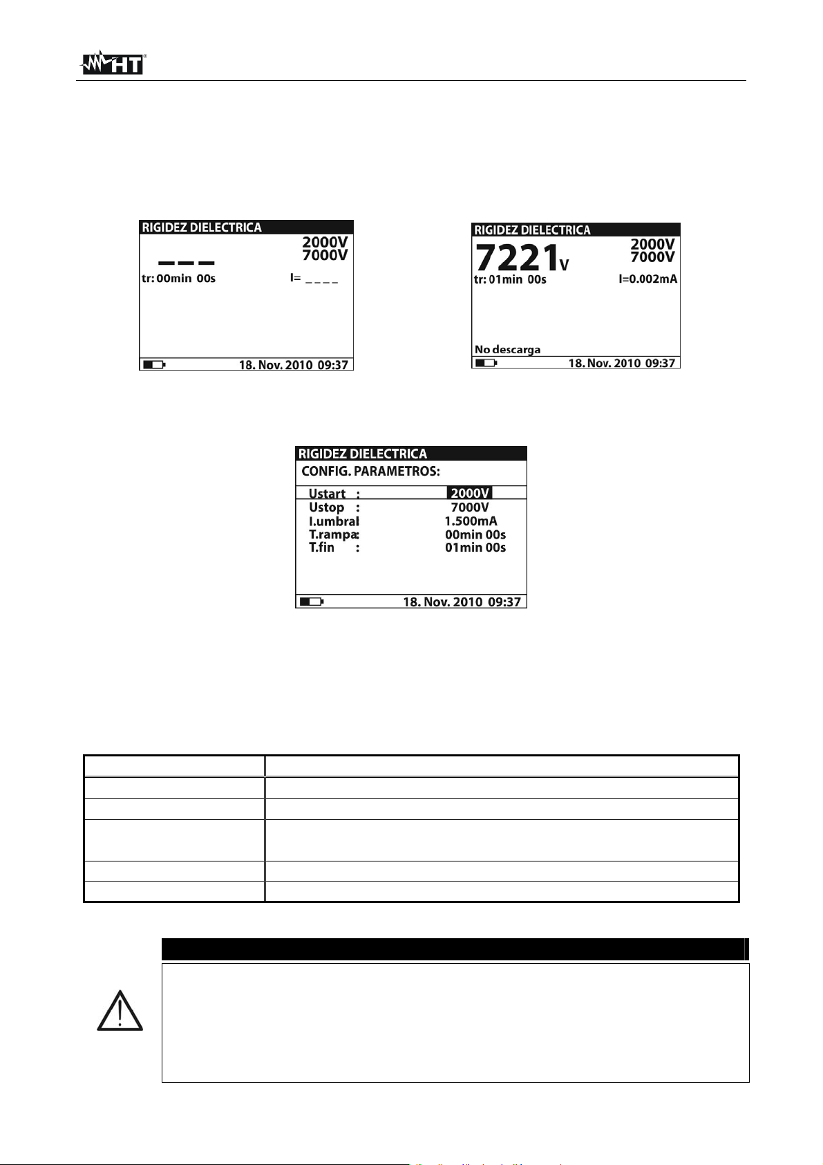
HT7052
6.8 PRUEBA DE RIGIDEZ DIELÉCTRICA EN CC
6.8.1 Configuración de los parámetros
1. Encienda el instrumento pulsando la tecla ON/OFF
2. Seleccione con las teclas flecha o la función “RIGIDEZ’ DIELÉCTRICA” sobre el
menú principal y confirme con la tecla SELECT. La pantalla Fig. 43 es mostrada
Fig. 43: Pantalla inicial prueba rigidez Fig. 44: Pantalla final prueba rigidez
3. Pulse nuevamente al tecla SELECT para entrar en el menú de configuración de los
parámetros de medida. El instrumento muestra la pantalla Fig. 45
Fig. 45: Pantalla configuración parámetros
4. Utilice las teclas flecha o para la selección de los parámetros. La siguiente
muestra el significado de los parámetros de medida
5. Configure los valores utilizando las teclas flecha o . Pulse la tecla SELECT para
pasar a eventuales subparámetros y repetir la configuración
6. Pulse la tecla ESC para guardar la configuración efectuada y volver a la pantalla de la
medida o bien la tecla START/STOP para salir de la pantalla y activar la medida
Nombre parámetro Descripción parámetro
Ustart
Ustop
I.umbral
Tensión de prueba inicial – Campo 500V10kV pasos 25V
Tensión de prueba final – Campo 500V10kV pasos 25V
Umbral límite corriente de descarga – Campo 0.001mA
5mA pasos 10A
T.rampa Duración de aplicación tensión de prueba para cada rampa
T.fin Duración aplicación tensión de prueba después valor final
Tabla 9: Configuración parámetros de medida
ATENCIÓN
Los temporizadores Trampa y Tfin son independientes. El tiempo máximo
configurable es 30min 60s. El temporizador Tfin inicia el completo el
tiempo de duración total de la rampa que puede ser estimado como:
Ttot-rampa Trampa * [(Ustop-Ustart) / 25V]
Si el temporizador Trampa es configurado a 00min 00s la rampa de tensión
se incrementa aproximátivamente de 25V cada 2s
ES - 28
Page 71

HT7052
6.8.2 Ejecución de la medida
1. Encienda el instrumento pulsando el tecla ON/OFF
2. Seleccione con las teclas flecha o la función “RIGIDEZ’ DIELÉCTRICA” sobre el
menú principal y confirme con la tecla SELECT. La pantalla Fig. 43 es mostrada en el
in strumento
3. Conecte la clavija roja del Terminal 1 o del Terminal 2 (ver § 4.2) en la entrada
+OUTPUT y la clavija del cable negro de la Punta 2 (ver § 4.2) en la entrada –
OUTPUT
4. Conecte la punta del Terminal 1 o del Terminal 2 (positivo) y el cable negro de los
Terminales 2 (negativo) en el objeto en prueba (negativo) del objeto en prueba (ver
Fig. 46)
Fig. 46: Conexión del instrumento para prueba de rigidez dieléctrica
5. Pulse la tecla START/STOP para activar la medida
6. Espere la caducidad de los temporizadores configurados o la verificación de la
descarga dieléctrica. El resultado de la prueba es presente en el visualizador (ver Fig.
44) con significado de la función mostrada en la Tabla 10
7. Espere la descarga automática del objeto en prueba
8. Para el guardado del resultado en memoria ver § 7
Parámetro visualizador Descripción
2000V
7000V
7221V
Tensión de prueba inicial configurada
Tensión de prueba final configurada
Tensión de prueba final medida
I=0.002mA Corriente de descarga medida
Tm:01min 00s Tiempo de medida
Tabla 10: Significado parámetros para prueba rigidez dieléctrica
ATENCIÓN
La descarga dieléctrica se verifica cuando la corriente medida supera el
umbral configurada del parámetro Itrigg (ver § 6.8.1)
El temporizador muestra el tiempo necesario para el completo de cada
rampa durante la medida y el tiempo del termino de la medida
Durante la medida, sobre el visualizador aparece el símbolo de advertencia
alta tensión, que recuerda al usuario el peligro de tensiones peligrosas de
salida
ES - 29
Page 72

HT7052
7 OPERACIONES CON MEMORIA
7.1 GUARDADO, RELLAMADO SOBRE EL VISUALIZADOR Y CANCELACIÓN DE
LOS RESULTADOS
GUARDADO DE DATOS
1. Con resultado de la medida presente en el visualizador pulse la tecla MEM. La pantalla
Fig. 47 es mostrada por el instrumento:
MEM BOR REL nnnn
Fig. 47: Guardar datos en memoria
2. Utilice las teclas flecha o y seleccione el opcional “MEM” el número “nnnn” indica
la localización de memoria en en cual será guardado el dato
3. Pulse la tecla MEM para confirmar la operación. Una doble breve señal acústica es
mostrado por el instrumento
RELLAMADO VISUALIZADOR DE LOS RESULTADOS
1. Pulse la tecla MEM, utilice las teclas flecha o para seleccionar la opción REL y
confirme con la tecla MEM. El instrumento muestra el valor en el visualizador del último
resultado guardado en memoria
2. Utilice las teclas flecha o para seleccionar y visualizar los datos correspondientes
a la localización de memoria precedente
3. EI dato rellamado con la indicación “G” indica la presencia de una pantalla gráfica
además de la numérica. Pulse la tecla SELECT para visualizar la pantalla gráfica y
ESC para volver a la anterior numérica
4. Pulse la tecla ESC para salir de la función y volver al modo de medida
CANCELACIÓN DE LOS RESULTADOS
1. Para la cancelación total de la memoria interna seleccione el parámetro “Canc.
memoria (ver el § 5.2), pulse la tecla SELECT y confirme con tecla MEM. Pulse ESC
per salir de la función
2. Pulse MEM para confirmar o ESC para salir de la función
3. Para cancelar la última medida guardada pulse la tecla MEM, utilice las teclas flecha
o para selecionar la opción BOR y confirme con la tecla MEM. Un doble breve
señal acústica es mostrada en el instrumento para confirmar la operación
ES - 30
Page 73

HT7052
8 CONEXIÓN DEL INSTRUMENTO AL PC
Los datos guardados en la memoria interna del instrumento pueden ser transferidos a un
PC utilizando el programa de gestión TeraView incluido en dotación
El programa de gestión TeraView permite efectuar las siguientes operaciones:
Descargar los datos del instrumento
Definir las configuraciones personalizadas sobre el informe final de impresión
Analizar los resultados de las medidas con visualización numéricas y gráficas
Impresión de los informes finales de medida
Exportar los datos de medida en formato texto (TXT)
REQUISITOS MÍNIMOS DE SISTEMA
Pentium III – 500MHz
512 MB RAM
100 MB libres sobre HD
Lector CD-ROM
Puerto serie/USB
Resolución pantalla 800x600
Sistema operativo Windows: Win2k/XP/Vista/Win7 a 32 bit y 64 bit
8.1 INSTALACIÓN DEL PROGRAMMA DE GESTIÓN Y CONFIGURACIÓN INICIAL
(WIN XP)
1. Cierre todas las aplicaciones activas sobre el PC
2. Inserte el CD-ROM en dotación en el lector del PC
3. Ejecute el archivo “TeraView.exe” presente sobre el CD-ROM para iniciar el
procedimiento de instalación guiada del programa TeraView
4. Encienda el instrumento, configure el modo de comunicación USB (ver § 5.2) y
conecte a un puerto USB del PC a través del cable en dotación
5. Abra la carpeta “Handbook” y ejecute el archivo “Instal_USB_neutral.pdf” a fin de
instalar el driver USB sobre el PC que permite el reconocimiento del instrumento
6. Ejecute el programa TeraView
7. Seleccione el comando “Config Contraseña…”, inserte el número de serie del
instrumento y la contraseña (indicada en la etiqueta del CD-ROM incluido en dotación)
y confirme con “Conforme” (ver Fig. 48)
Fig. 48: Inserción contraseña inicial
ES - 31
Page 74

HT7052
8. Seleccione el comando “Config Puerto COM…” y clique sobre el botón
“Autobúsqueda” con el fin de verificar el reconocimiento del instrumento con el PC (ver
Fig. 49)
9. Un mensaje como el de la Fig. 50 indica el correcto reconocimiento con el PC
Fig. 49: Conexión instrumento a un PC
Fig. 50: Reconocimiento correcto del instrumento
10. En el caso en el cual el reconocimiento del instrumento no sea correcto puede ser
necesario configurar correctamente el puerto serie “virtual” COM asociado al driver
USB instalado anteriormente. El programa TeraView puede reconocer el puerto serie
desde el COM1 al COM16. Para modificar el puerto COM asociado al driver proceda
como sigue:
Botón derecho del ratón sobre el icono “Mi PC” presente sobre el escritorio del PC y
seleccione la función “Propiedades”
Pestaña “Hardware” “Administrador de dispositivos” “Puertos (COM & LPT)
Posicionarse sobre la función “USB Serie Puerto (COMxx)” botón derecho
“Propiedades”
Seleccione “Configuración del puerto” “Opciones Avanzadas…”
En el menú cambie el puerto “COMxx” por un COM1…COM16 libre
Confirme las operaciones de cada ventana y vuelva al software TeraView
Para información sobre el uso del software TeraView haga referencia a la Ayuda en
línea del mismo programa
ES - 32
Page 75

HT7052
9 MANTENIMIENTO
9.1 GENERALIDADES
El instrumento que Usted ha adquirido es un instrumento de precisión. Durante el uso y el
almacenamiento respete las recomendaciones enumeradas en este manual para evitar
posibles daños o peligros durante el uso. No utilice el instrumento en entornos
caracterizados por elevadas tasas de humedad o temperatura. No lo exponga
directamente a la luz del sol. Apague siempre el instrumento después de su uso. En
ningún caso quite el panel frontal del instrumento. El instrumento no requiere ningún tipo
de mantenimiento
9.2 SUSTITUCIÓN Y RECARGA DE LAS BATERÍAS
El instrumento ha sido fabricado para ser alimentado con baterías recargables a través del
cargador de baterías integrado con conexión a la red eléctrica. El símbolo “ “ parte
inferior izquierda, indica que las baterías están descargadas y deben ser recargadas
En el primer uso del instrumento, conéctelo a la red eléctrica durante
aproximadamente 20 horas con el fin de recargar completamente las
baterías (corriente de recarga típica 600mA). Normalmente son necesarios
3 cíclos de carga/descarga para el buen funcionamiento de las baterías
El instrumento puede ser continuamente conectado a la red eléctrica
también después del completo ciclo de carga de las baterías internas
El instrumento no puede ser encendido con alimentación exterior con falta
de las baterías internas
En caso de sustitución de las baterías internas opere como sigue:
La tensión de batería es 7.2V CC. Utilice exclusivamente 6x1.2V baterías
recargables NiMH tipo IEC LR20 (diámetro = 33mm, largo = 58mm)
1. Apague el instrumento, desconecte cada terminal de medida y cable de alimentación
antes de operar para la sustitución de las baterías
2. Quite los dos tornillos (ver Fig. 1 – Parte 15) y la tapa de baterías
3. Sustituya las seis baterías internas por otras del mismo tipo respetando la polaridad
indicada en el interior de la tapa de pilas
4. Coloque la tapa de pilas
5. No disperse las baterías usadas en el medio ambiente. Utilice los contenedores
especificos para su reciclado
ATENCIÓN
ATENCIÓN
9.3 LIMPIEZA DEL INSTRUMENTO
Para la limpieza del instrumento utilice un paño limpio y seco. No use nunca paños
húmedos, disolvente, agua, etc
9.4 FIN DE VIDA
ATENCIÓN: el símbolo indica que el aparato y sus accesorios deben ser
reciclados separadamente y tratados de modo correcto
ES - 33
Page 76

HT7052
10 ESPECIFICACIONES TÉCNICAS
La incertidumbre es calculada como [% de la lectura + (número de dígitos) * resolución] a
las condiciones de referencia indicadas en el § 0
Medida de Resistencia de aislamiento
Campo de medida Resolución Incertidumbre
120k 999k 1k
1.00M 9.99M 0.01M
10.0M 99.9M 0.1M
100M 999M 1M
1.00G 9.99G 0.01G
10.0G 99.9G 0.1G
100G 999G 1G
1.00T 10.00T 0.01T (15.0 lectura + 3 dig.)
El valor de FE de la resistencia de aislamiento es definido como: RFS = 1G * Utest [V]
Tensión de prueba nominal: 500 10kV CC
Corriente de prueba nominal: > 1mA
Corriente de cortocircuito: 5mA 10%
Descarga automática objeto en prueba: Si
Campo de medida tensión prueba Resolución Incertidumbre
0 9999V
10kV
Tensión de prueba nominal: 500 10kV CC programable en pasos de 25V
Incertidumbre tensión de prueba: -0 / +10% + 20V
Potencia de salida: 10W max
1V
0.1kV
Campo de medida corriente prueba Resolución Incertidumbre
0.00 9.99nA
10.0 99.9nA
100 999nA
0.01nA
0.1nA
1nA
1.00 9.99A 0.01A
10.0 9.99A 0.1A
100 999A 1A
1.00 5.50mA
0.01mA
Rechazo de ruido de corriente (carga resistiva)
Opciones Filtro Corriente máxima @ 50Hz (mA rms)
Fil0 1.5
Fil1 2.5
Fil2 4.5
Fil3 5
Diagrama Tensión de prueba – Resistencia
(5.0 lectura + 3 dig.)
(3.0 lectura + 3V)
3.0 lectura
(5.0 lectura + 0.05nA)
12
10
8
6
[ kV ]
4
2
0
0,1 1 10 100
[ M ]
Utest=10kV Utest=5kV
ES - 34
Page 77

HT7052
Medida parámetros DAR, PI, DD
Campo de medida Resolución Incertidumbre
0.01 9.99
10.0 100.0
Campo medida capacidad para prueba DD: 5nF 50F
0.01
0.1
(5.0 lectura + 2 dig)
5.0 lectura
Medida aislamiento con rampa de tensión
Campo de medida tensión prueba Resolución Incertidumbre
2000 9999V
10kV
Tensión de prueba nominal: 2000 10kV CC programable en pasos de 125V
Incertidumbre tensión de prueba: -0 / +10% + 20V
1V
0.1kV
(3.0 lectura + 3V)
3.0 lectura
Prueba rigidez dieléctrica CC
Campo de medida tensión prueba Resolución Incertidumbre
500 9999V
10kV
Campo medida corriente descarga Resolución Incertidumbre
0.000 0.009mA
0.01 5.50mA
Tensión de prueba nominal: 500 10kV CC programable en pasos de 25V
Incertidumbre tensión de prueba: -0 / +10% + 20V
1V
0.1kV
0.001mA
0.01mA
(3.0 lectura + 3V)
3.0 lectura
(3.0 lectura + 3 dig)
3.0 lectura
Tensión CA o CC
Campo de medida Resolución Incertidumbre
0 600V
Impedancia de entrada: 3M 10%
1V
(3.0 lectura + 4V)
Frecuencia tensión Resolución Incertidumbre
0 e 45.0 65.0Hz
Frecuencia entre 0 y 45Hz: visualización < 45Hz
Frecuencia > 65Hz: visualización > 65Hz
0.1Hz
0.2Hz
Capacidad
Campo de medida Resolución Incertidumbre
0.0 99.9nF
100 999nF
1.00 50.0F 0.01F
El valor de FE de la capacidad es definido como: CFS = 10F * Utest [kV]
0.1nF
1nF
(5.0 lectura + 2 dig)
10.1 NORMAS DE SEGURIDAD
Seguridad instrumento: IEC/EN61010-1, IEC/EN61557-2
Seguridad accesorios de medida: IEC/EN61010-031
Aislamiento: doble aislamiento
Protección: IP44 (maleta cerrada)
Nivel de Polución: 2
Categoría de sobretensión: CATIV600V (respecto tierra), max 600V entre
entradas
Altitud máx de uso: 2000m
ES - 35
Page 78

HT7052
10.2 CARACTERÍSTICAS GENERALES
Características mecánicas
Dimensiones (Lx an x H): 360 x 330 x 160mm
Peso (con baterías): 5.5kg
Alimentación
Alimentación externa: 90-260V AC, 45-65Hz, 60VA
Alimentación interna: 6 x 1.2V recargables NiMH tipo IEC LR20
Indicación batería descargada: símbolo ““ “ en el visualizador
Autonomía baterías: aprox. 4 horas (prueba continuidad a 10kV)
Visualizador
Características: LCD matriz de puntos, retroiluminado (160x116pxl)
Memoria
Características: 1000 posiciones de memoria
Descarga objeto en prueba
Características: automática después cada prueba, resist. 425 10%
Conexión a PC
Interfaz serie RS-232: optoaisolada (2400,4800,9600,19200 baud, 1, N)
Interfaz USB: tipo B estándar, 115000 baudios
10.3 AMBIENTE
Temperatura de referencia: 10°C ÷ 30°C
Humedad de referencia: 40%HR ÷ 60%HR
Temperatura de uso: -10°C ÷ 50°C
Humedad relativa admitida: <90%HR
Temperatura almacenamiento: -20°C ÷ 70°C
Humedad de almacenamiento: <90%HR
Este instrumento es conforme a los requisitos de la Directiva Europea sobre baja
tensión 2006/95/CE (LVD) y de la directiva EMC 2004/108/CE
10.4 ACCESORIOS
N 1 Punta de prueba rojo, protección 10kV, 2m
N 2 Puntas de prueba (rojo/negro), protección base 10kV (doble protección 5kV), 2m
N 2 Coccodrillos (rojo/negro), protección base 10kV (doble protección 5kV)
N 1 Punta de prueba Guarda verde
N 1 Coccodrillo verde
N 1 Cable de alimentacción
N 1 Cable USB
N 1 Cable RS-232
Software “TeraView” en CD-ROM
6 x 1.2V pilas NiMH IEC LR20
Manual de instrucciones
Certificado de calibracción ISO9000
ES - 36
Page 79

HT7052
11 ASISTENCIA
11.1 CONDICIONES DE GARANTÍA
Este instrumento está garantizado contra cada defecto de materiales y fabricaciones,
conforme con las condiciones generales de venta. Durante el período de garantía, las
partes defectuosas pueden ser sustituidas, pero el fabricante se reserva el derecho de
repararlo o bien sustituir el producto
Siempre que el instrumento deba ser reenviado al servicio post - venta o a un distribuidor,
el transporte será a cargo del cliente. La expedición deberá, en cada caso, ser
previamente acordada
Acompañando a la expedición debe ser incluida una nota explicativa sobre los motivos del
envío del instrumento
Para la expedición utilice sólo en embalaje original, cada daño causado por el uso de
embalajes no originales será a cargo del cliente
El constructor declina toda responsabilidad por daños causados a personas u objetos.
La garantía no se aplica en los siguientes casos:
Reparaciones y/o sustituciones de accesorios y pilas (no cubiertas por la garantía)
Reparaciones que se deban a causa de un error de uso del instrumento o de su uso
con aparatos no compatibles
Reparaciones que se deban a causa de embalajes no adecuados
Reparaciones que se deban a la intervención de personal no autorizado
Modificaciones realizadas al instrumento sin explícita autorización del constructor
Uso no contemplado en las especificaciones del instrumento o en el manual de uso
El contenido del presente manual no puede ser reproducido de ninguna forma sin la
autorización del constructor
Nuestros productos están patentados y las marcas registradas. El constructor se
reserva en derecho de aportar modificaciones a las características y a los precios si
esto es una mejora tecnológica.
11.2 ASISTENCIA
Si el instrumento no funciona correctamente, antes de contactar con el Servicio de
Asistencia, controle el estado de las pilas, de los cables y sustitúyalos si fuese necesario
Si el instrumento continúa manifestando un mal funcionamiento controle si el
procedimiento de uso del mismo es correcto según lo indicado en el presente manual
Si el instrumento debe ser reenviado al servicio post venta o a un distribuidor, el
transporte es a cargo del Cliente. La expedición deberá, en cada caso, previamente
acordada. Acompañando a la expedición debe incluirse siempre una nota explicativa
sobre el motivo del envío del instrumento. Para la expedición utilice sólo el embalaje
original, daños causados por el uso de embalajes no originales serán a cargo del Cliente
ES - 37
Page 80

Page 81

FRANÇAIS
Manuel d’utilisation
Copyright HT ITALIA 2013 Version FR 2.00 - 02/01/2013
Page 82

Page 83

HT7052
Table des matières:
1 PRECAUTIONS ET MESURES DE SECURITE .................................................................. 2
1.1 Instructions préliminaires ...................................................................................................................... 2
1.2 Pendant l’utilisation ............................................................................................................................... 3
1.3 Après l’utilisation ................................................................................................................................... 3
1.4 Définition de catégorie de mesure (surtension) .................................................................................... 3
2 DESCRIPTION GENERALE ................................................................................................ 4
2.1 Fonctions de l'instrument ...................................................................................................................... 4
3 PREPARATION A L'UTILISATION...................................................................................... 5
3.1 Vérification initiale ................................................................................................................................. 5
3.2 Alimentation de l’instrument ................................................................................................................. 5
3.3 Calibration ............................................................................................................................................. 5
3.4 Conservation ......................................................................................................................................... 5
4 NOMENCLATURE ............................................................................................................... 6
4.1 Description de l’instrument ................................................................................................................... 6
4.2 Usage des bornes de mesure .............................................................................................................. 7
5 OPERATIONS INITIALES .................................................................................................... 8
5.1 Conditions à l'allumage ......................................................................................................................... 8
5.1.1 Alimentation de l’instrument ....................................................................................................... 8
5.1.2 Usage du rétro éclairage ............................................................................................................ 8
5.1.3 Autocalibration ........................................................................................................................... 8
5.2 Configuration des paramètres de système ........................................................................................... 9
6 EXECUTION DES MESURES ............................................................................................ 10
6.1 Théorie sur la mesure de résistance d'isolement ............................................................................... 10
6.1.1 Test en fonction du temps – Tests diagnostiques .................................................................... 12
6.1.2 Test de rigidité diélectrique ...................................................................................................... 15
6.2 Borne de garde ................................................................................................................................... 16
6.3 Usage des filtres internes ................................................................................................................... 17
6.3.1 Signification du filtrage interne ................................................................................................. 17
6.4 Mesure de tension .............................................................................................................................. 18
6.5 Mesure de résistance d'isolement ...................................................................................................... 19
6.5.1 Réglage des paramètres .......................................................................................................... 19
6.5.2 Exécution de la mesure ............................................................................................................ 20
6.6 Tests diagnostiques sur la qualité des matériaux .............................................................................. 22
6.6.1 Réglage des paramètres .......................................................................................................... 22
6.6.2 Exécution de la mesure ............................................................................................................ 23
6.7 Mesure d'isolement avec rampe de tension ....................................................................................... 25
6.7.1 Réglage des paramètres .......................................................................................................... 25
6.7.2 Exécution de la mesure ............................................................................................................ 26
6.8 Test de rigidité diélectrique en DC ..................................................................................................... 28
6.8.1 Réglage des paramètres .......................................................................................................... 28
6.8.2 Exécution de la mesure ............................................................................................................ 29
7 OPERATIONS AVEC LA MEMOIRE ................................................................................. 30
7.1 Sauvegarde, rappel à l'écran et effacement des résultats ................................................................. 30
8 CONNEXION DE L'INSTRUMENT AU PC ........................................................................ 31
8.1 Installation du logiciel et configurations initiales (Win XP) ................................................................. 31
9 ENTRETIEN ....................................................................................................................... 33
9.1 Aspects généraux ............................................................................................................................... 33
9.2 Remplacement et recharge des batteries .......................................................................................... 33
9.3 Nettoyage de l’instrument ................................................................................................................... 33
9.4 Fin de la durée de vie ......................................................................................................................... 33
10 SPECIFICATIONS TECHNIQUES ..................................................................................... 34
10.1 Normes de sécurité............................................................................................................................. 35
10.2 Caractéristiques générales ................................................................................................................. 36
10.3 Environnement .................................................................................................................................... 36
10.4 Accessoires ........................................................................................................................................ 36
11 ASSISTANCE ..................................................................................................................... 37
11.1 Conditions de garantie ........................................................................................................................ 37
11.2 Assistance .......................................................................................................................................... 37
FR - 1
Page 84

HT7052
1 PRECAUTIONS ET MESURES DE SECURITE
Cet instrument a été conçu conformément aux réglementations CEI/EN61557-2 et
CEI/EN61010-1, relatives aux instruments de mesure électroniques
Pour votre propre sécurité et afin d’éviter tout dommage à l’instrument,
veuillez suivre avec précaution les instructions décrites dans ce manuel et lire
attentivement toutes les remarques précédées du symbole
Avant et pendant l’exécution des mesures, veuillez respecter scrupuleusement ces
indications:
Ne pas mesurer dans des endroits humides, en la présence de gaz ou matériaux
explosifs, de combustibles ou dans des endroits poussiéreux
Même si on n'est pas en train d'exécuter de mesures, ne pas toucher le circuit sous
test, de parties métalliques exposées avec des bornes de mesure inutilisées, des
circuits, etc
Ne pas effectuer de mesures si vous détectez des anomalies sur l’instrument telles qu’une
déformation, une cassure, des fuites de substances, une absence d’affichage de l’écran,
etc
Prêter une attention particulière lorsque vous mesurez des tensions dépassant 25V
dans des endroits particuliers (chantiers, piscines, etc.) et 50V dans des endroits
ordinaires afin d’éviter le risque de chocs électriques
Dans ce manuel, et sur l’instrument, on utilisera les symboles suivants:
ATTENTION: s'en tenir aux instructions reportées dans ce manuel. Une
utilisation inappropriée pourrait endommager l’instrument et créer des situations
dangereuses pour l'utilisateur
ATTENTION
Attention tensions dangereuses: risque de chocs électriques
Tension ou courant DC
Instrument à double isolement
1.1 INSTRUCTIONS PRELIMINAIRES
Cet instrument a été conçu pour l'utilisation dans un environnement avec niveau de
pollution 2
Il peut être utilisé pour des vérifications sur installations électriques industrielles jusqu'à
la CAT IV 600V à la terre avec une tension maximale de 600V entre les entrées
Veuillez suivre les normes de sécurité principales visant à protéger l'utilisateur contre
des courants dangereux et l’instrument contre une utilisation erronée
N'utiliser l'instrument que lorsqu'il est placé sur des surfaces horizontales nivelées et
adéquates autres que le sol
Seuls les accessoires fournis avec l’instrument garantissent la conformité avec les
normes de sécurité. Ils doivent être en bon état et, si nécessaire, remplacés à
l’identique
Ne pas mesurer de circuits dépassant les limites de tension et de courant spécifiées
Ne pas effectuer de mesures dans des conditions environnementales en dehors des
limites indiquées dans ce manuel
Avant de connecter les embouts au circuit à tester, vérifier que la fonction correcte a
été sélectionnée
S'assurer que l'objet sous test est débranché du réseau avant de lancer la mesure de
la résistance d'isolement
FR - 2
Page 85

HT7052
1.2 PENDANT L’UTILISATION
Lire attentivement les recommandations et instructions suivantes:
ATTENTION
Le non-respect des avertissements et/ou instructions pourrait endommager
l’instrument et/ou ses composants ou mettre en danger l’utilisateur. Si pendant
l'utilisation le symbole de batterie déchargée s'affiche, brancher le câble
d'alimentation pour recharger la batterie. Il est possible d'exécuter des
mesures pendant la recharge de la batterie
Avant de sélectionner une nouvelle fonction, déconnecter les embouts de mesure du circuit
Lorsque l’instrument est connecté au circuit sous test, ne jamais toucher les bornes inutilisées
Eviter de mesurer une résistance si des tensions externes sont présentes. Même si
l’instrument est protégé, une tension excessive pourrait être à l’origine d’un
dysfonctionnement de l'instrument
En cas de mesure sur des objets ayant des capacités internes élevées (tests sur de
longs câbles, etc.), la décharge automatique peut ne pas être presque immédiate à la
fin de la mesure. Dans ces cas-là, l'instrument affiche le message: «Attendere la
scarica dell'oggetto» (Attendre la décharge de l'objet)
Dans les opérations avec charges capacitives, considérer que le fait de charger 40nF
avec 1kV ou 5nF avec 10kV représente des conditions dangereuses
1.3 APRES L’UTILISATION
Une fois les mesures terminées, éteindre l'instrument par la touche ON/OFF
1.4 DEFINITION DE CATEGORIE DE MESURE (SURTENSION)
La norme «CEI 61010-1: Prescriptions de sécurité pour les instruments électriques de
mesure, le contrôle et l’utilisation en laboratoire, Partie 1: Prescriptions générales», définit
ce qu’on entend par catégorie de mesure, généralement appelée catégorie de surtension.
A la § 6.7.4: Circuits de mesure, on lit:
Les circuits sont divisés dans les catégories de mesure qui suivent:
La catégorie de mesure IV sert pour les mesures exécutées sur une source
d'installation à faible tension
Par exemple, les appareils électriques et les mesures sur des dispositifs primaires à protection
contre surtension et les unités de contrôle d’ondulation
La catégorie de mesure III sert pour les mesures exécutées sur des installations dans
les bâtiments
Par exemple, les mesures sur des panneaux de distribution, des disjoncteurs, des câblages, y
compris les câbles, les barres, les boîtes de jonction, les interrupteurs, les prises d’installation
fixe et le matériel destiné à l’emploi industriel et d’autres instruments tels que par exemple les
moteurs fixes avec connexion à une installation fixe
La catégorie de mesure II sert pour les mesures exécutées sur les circuits connectés
directement à l'installation à faible tension
Par exemple, les mesures effectuées sur les appareils électroménagers, les outils portatifs et
sur des appareils similaires
La catégorie de mesure I sert pour les mesures exécutées sur des circuits n’étant pas
directement connectés au RESEAU DE DISTRIBUTION
Par exemple, les mesures sur des circuits ne dérivant pas du RESEAU et des circuits dérivés
du RESEAU spécialement protégés (interne). Dans le dernier cas mentionné, les tensions
transitoires sont variables; pour cette raison, (OMISSIS) on demande que l’utilisateur
connaisse la capacité de résistance transitoire de l’appareil
FR - 3
Page 86

HT7052
2 DESCRIPTION GENERALE
L'instrument HT7052 que vous venez d'acheter, si utilisé conformément à ce qui est décrit
dans ce manuel, vous garantit des mesures soignées et fiables, ainsi que le maximum de
sécurité, grâce à son développement de toute nouvelle conception assurant le double
isolement et l'obtention de la catégorie de surtension IV
2.1 FONCTIONS DE L'INSTRUMENT
Mesure de la résistance d'isolement avec échelle de mesure jusqu'à 10T
Tension d'essai pouvant être programmée de 500V à 10kV DC par pas de 25VDC
Graphiques de la résistance d'isolement en fonction du temps
Timer programmable de 1s à 30min
Décharge automatique de l'objet à la fin de l'essai
Mesure de capacité
Résistance d'isolement avec la tension d'essai à gradins
Réglage de jusqu'à 5 tensions d'essai
Timer programmable de 1s à 30min pour chaque gradin
Mesure de l’Indice de polarisation (PI), du rapport d'absorption diélectrique (DAR) et du
rapport de décharge diélectrique (DD)
PI = Riso (t2) / Riso (t1)
DAR = R1min / R15s
DD = Idis1min / C*U
Essai de tension appliquée (rigidité diélectrique) jusqu'à 10kV DC
Rampe de tension programmable de 500V à 10kV DC
Résolution élevée (25V environ par pas)
Seuil de courant de décharge programmable jusqu'à 5mA
Mesure de tension et fréquence jusqu'à 600V AC/DC
Un afficheur LCD à matrice de points permet des lectures faciles des résultats de mesure
et des paramètres de contrôle associés. Son fonctionnement est clair et simple ; pour faire
marcher l'instrument, l'utilisateur ne nécessite d'aucune formation spécifique (en plus de la
lecture et compréhension de ce manuel d'utilisation)
L'instrument peut mémoriser les résultats des essais. Le logiciel professionnel pour
Windows fourni de dotation permet de transférer au PC les résultats des essais et d'autres
paramètres
FR - 4
Page 87

HT7052
3 PREPARATION A L'UTILISATION
3.1 VERIFICATION INITIALE
L’instrument a fait l’objet d’un contrôle mécanique et électrique avant d’être expédié.
Toutes les précautions possibles ont été prises pour garantir une livraison de l’instrument
en bon état
Toutefois, il est recommandé d’en effectuer un contrôle rapide afin de détecter des
dommages qui auraient pu avoir lieu pendant le transport. En cas d’anomalies, n’hésitez
pas à contacter votre commissionnaire de transport ou votre revendeur
S’assurer que l’emballage contient tous les accessoires listés à la § 10.4. Dans le cas
contraire, contacter le revendeur. S’il était nécessaire de renvoyer l’instrument, veuillez
respecter les instructions dont à la § 11
3.2 ALIMENTATION DE L’INSTRUMENT
L'instrument est alimenté par 6 batteries internes de 1.2V IEC LR20 NiMH rechargeables
par le chargeur interne connecté au réseau. Le symbole « » en bas à gauche indique
que les batteries sont déchargées et doivent être rechargées. Pour remplacer ou
recharger les piles, suivre les instructions de la § 9.2
N'utiliser que des batteries rechargeables NiMH de type IEC LR20
Lors de la première utilisation de l'instrument, le brancher sur le réseau
électrique pendant 20 heures environ de sorte à recharger complètement
les batteries (courant de recharge normal 600mA). Normalement il faut 3
cycles de charge/décharge pour le fonctionnement à régime de la batterie
ATTENTION
3.3 CALIBRATION
L’instrument est conforme aux spécifications techniques décrites dans ce manuel. Ses
performances sont garanties pendant un an à compter de la date d'achat
3.4 CONSERVATION
Afin d’assurer la précision des mesures et protéger l'instrument contre toute panne
possible, après une longue période de stockage en conditions environnementales
extrêmes, il est conseillé d’attendre le temps nécessaire pour que l’instrument revienne
aux conditions normales (voir Conditions environnementales à la § 10.3)
FR - 5
Page 88

HT7052
4 NOMENCLATURE
4.1 DESCRIPTION DE L’INSTRUMENT
Fig. 1: Description de l’instrument
LEGENDE:
1 Touche ON/OFF pour allumer/éteindre l'instrument
2 Touche START/STOP pour démarrer/terminer les mesures
3-4-5-6
Touches , , , pour sélectionner les paramètres et régler les
valeurs
7 Touche SELECT pour accéder au mode de réglage des paramètres
8 Touche ESC pour quitter le mode de réglage des paramètres
9 Touche MEM pour sauvegarder, rappeler à l'écran et effacer les mesures
10 Touche LIGHT pour activer/désactiver le rétro éclairage
11 Entrée positive pour mesure d'isolement +OUTPUT
12 -13 Bornes GUARD pour éliminer les courants de fuite superficiels
14 Entrée négative pour mesure d'isolement -OUTPUT
15 Vis de fixation du compartiment à batteries
16 Couvercle du compartiment à batteries
17 Port USB pour connexion instrument à PC
18 Port RS-232 opto-isolé pour connexion instrument à PC
19 Connecteur d'entrée pour alimentation instrument
20 Afficheur LCD
21 Etiquette avec numéro de série de l’instrument
FR - 6
Page 89

HT7052
4.2 USAGE DES BORNES DE MESURE
Borne 1
Cette borne de mesure est conçue pour exécuter des
mesures typiques de résistance d'isolement
Caractéristiques
Câble blindé pour augmenter l'immunité aux
perturbations externes et améliorer la précision des
mesures
Isolement câble blindé jaune: 12kVDC
Longueur câble = 2m
Astuce avec double isolement et la protection
10kVDC
Connecteur banane rouge avec protection de base
10kVDC et double protection 5kVDC
Bornes 2
Borne de garde
Connecteur de garde banane vert: CAT IV 600V
Ces bornes de mesure sont conçues pour exécuter des
tests diagnostiques et des essais de durée sur
l'isolement
Caractéristiques
Câbles blindés pour augmenter l'immunité aux
perturbations externes et améliorer la précision des
mesures
Isolement câbles blindés jaunes: 12kVDC
Longueur câbles = 2m
Connecteur banane rouge/noir avec protection de
base 10kVDC et double protection 5kVDC
Connecteurs de garde banane vert: CAT IV 600V
Bornes crocodile rouge/noir avec protection de base
10kVDC et double protection 5kVDC
Cette borne de mesure est utilisée pour la connexion à
l'objet sous test afin d'éliminer le courant de fuite
superficiel (voir la § 6.2)
Caractéristiques
Câble banane-banane, CAT IV 600V
Borne crocodile CAT IV 600V
FR - 7
Page 90

HT7052
5 OPERATIONS INITIALES
5.1 CONDITIONS A L'ALLUMAGE
5.1.1 Alimentation de l’instrument
En branchant l'instrument éteint sur le réseau électrique, le chargeur
interne commence la recharge des batteries internes alors que l'instrument
reste éteint. Dans de telles conditions, le symbole de batterie clignote à
l'écran pour indiquer que l'opération de recharge est en cours
Si les batteries sont défectueuses ou font défaut et l'instrument est
connecté au réseau, l'instrument ne s'allume pas
Si les batteries sont défectueuses ou font défaut, le chargeur interne
n'exécute aucune opération de recharge. L'écran ne montre que le
symbole de la fiche
Si l'instrument est allumé et connecté au réseau, il passe automatiquement
de l'alimentation par batterie à celle par le réseau et le symbole de la fiche
est montré à l'écran
Si l'instrument N'est PAS en mesure, le chargeur recharge les batteries
internes et le symbole de batterie clignote à l'écran pour indiquer que
l'opération de recharge est en cours
Il est recommandé de NE PAS connecter ou déconnecter l'instrument
5.1.2 Usage du rétro éclairage
du réseau électrique pendant une mesure
Instrument alimenté par la batterie
A l'allumage, le rétro éclairage de l'instrument est allumé automatiquement et peut être
éteint et/ou rallumé en appuyant sur la touche LIGHT
Instrument alimenté par le réseau
A l'allumage, le rétro éclairage de l'instrument est automatiquement éteint et peut être
allumé et/ou éteint à nouveau en appuyant sur la touche LIGHT
Fonction d'arrêt auto
L'instrument peut être éteint seulement en appuyant sur la touche ON/OFF. La fonction
d'arrêt auto n'est pas disponible pour permettre les tests d'isolement de longue durée
5.1.3 Autocalibration
A l’allumage, en appuyant sur la touche ON/OFF, après la page-écran d'introduction (voir
Fig. 1), l'instrument exécute son autocalibration interne (voir Fig. 3) où il faut que les
embouts soient déconnectés de l'instrument. Autrement, l'instrument demande de
détacher les embouts, d'éteindre et rallumer le dispositif
ATTENTION
Fig. 2: Page-écran
d'introduction
Fig. 3: Autocalibration Fig. 4: Menu principal
A la fin de l'opération, l'instrument présente le menu initial et est prêt pour les opérations
normales de mesure (voir la Fig. 4)
FR - 8
Page 91

HT7052
L’autocalibration permet d'empêcher la diminution de la précision en cas de mesure de
courants faibles. De cette façon, on compense les effets engendrés par des agents
externes, la température et l'humidité, etc. Il faut une nouvelle autocalibration si la
température ambiante varie de plus de 5°C. Si l'instrument détecte une condition erronée
pendant l’autocalibration, l'afficheur peut montrer les messages d'attention ci-dessous:
ATTENTION
TERMINALI COLLEGATI (BORNES CONNECTÉES): SCOLLEGARLI E
RIAVVIARE NUOVAMENTE LO STRUMENTO (LES DÉCONNECTER ET
REDÉMARRER L'INSTRUMENT)
CONDIZIONI FUORI SCALA (CONDITIONS HORS ÉCHELLE):
PREMERE START PER CONTINUARE (APPUYER SUR START POUR
CONTINUER)
Parmi les causes possibles des conditions externes au champ de mesure on trouve
l'humidité excessive, la température trop élevée, etc. Dans ce cas-là, les mesures peuvent
quand même être exécutées, mais les résultats pourraient ne pas être compris dans la
classe de précision déclarée dans les spécifications techniques (voir la § 10)
5.2 CONFIGURATION DES PARAMETRES DE SYSTEME
La fonction de configuration permet de sélectionner et de régler les paramètres (voir
Tableau 1) n'étant pas directement concernés par la mesure (voir Fig. 5 et Fig. 6). Dans la
partie inférieure de l'écran on montre l'état de l'alimentation
Fig. 5: Paramètres de configuration initiale Fig. 6: Paramètres de configuration setup
PARAMETRE VALEUR DESCRIPTION
Canc. memoria
Filtro
DIAG.
Tempo iniziale
Contrasto
Ora
Data
Porta COM
Langue
Inizializzazione
Fil1, Fil2, Fil3, Fil0 Sélection du filtre de réduction perturbation (voir
RS232 2400, RS232 4800,
RS232 9600, RS232 19200,
USB 115000
Ita, Eng, Esp, Deu, Fra Impostazione della lingua di sistema
Tableau 1: Configuration des paramètres de système
Effacement de la mémoire interne
§ 6.3)
Réglage du démarrage du timer dans les tests
0%…90%
diagnostiques en fonction du pourcentage de la
tension d'essai (voir § 6.1)
0%…100% Réglage du contraste de l'écran LCD
Réglage de l'heure courante (heure:minutes)
Réglage de la date courante (jour-mois-année)
Réglage du type de communication avec le PC et
vitesse de transfert des données
Seulement pour le service d'assistance HT ITALIA
1. Utiliser les touches fléchées ou pour sélectionner le paramètre
2. Utiliser les touches fléchées ou pour régler la valeur du paramètre sélectionné.
S'il y a deux paramètres ou plus par ligne (ex: date/heure), appuyer sur la touche
SELECT pour passer d'un paramètre à l'autre
3. Appuyer sur la touche ESC pour revenir au menu principal de l'instrument
FR - 9
Page 92

HT7052
6 EXECUTION DES MESURES
6.1 THEORIE SUR LA MESURE DE RESISTANCE D'ISOLEMENT
But de la mesure de résistance d'isolement
Les matériaux isolants représentent une partie importante de tout produit électrique. Les
propriétés des matériaux ne dépendent pas seulement de leurs caractéristiques
intrinsèques, mais aussi de la température, de la pollution, de l'humidité, des agents
externes, du stress électrique et mécanique, etc. La sécurité et la fiabilité de chaque
produit demandent un entretien régulier et un test périodique de l'isolement des matériaux
de sorte à permettre des conditions opérationnelles optimales. Pour tester l’isolement des
matériaux, on utilise des méthodes de mesure avec tensions d'essai élevées
Différence entre tensions d'essai DC et AC
Les tests utilisant des tensions DC sont largement acceptés tout comme les tensions AC
et/ou impulsives. Les tensions DC peuvent être utilisées pour des essais de décharge,
surtout si des courants de fuite capacitifs élevés interfèrent dans les mesures utilisant des
tensions CA ou impulsives. Elles sont normalement appliquées pour les mesures des
résistances d'isolement. Dans ces cas-là, la tension d'essai réelle à utiliser est établie
selon les caractéristiques de chaque objet. On les utilise moins dans les tests de rigidité
diélectrique où l'on n'a pas souvent la nécessité de stresser le matériau sous test
Tests d'isolement typiques
En ligne générale, les tests d'isolement comprennent les types ci-dessous:
Mesures simples de résistance d'isolement appelées également tests de contrôle
Mesure de la résistance d'isolement en fonction de la tension
Mesure de la résistance d'isolement en fonction du temps
Test de charge résiduelle après la décharge diélectrique
Le résultat de ces tests peut faciliter la décision concernant le remplacement éventuel de
l'isolement total du système. Il est recommandé d'exécuter des tests sur la résistance
d'isolement et des analyses diagnostiques dans les systèmes de transformateurs, les
moteurs électriques, les câbles et d'autres appareils électriques
Représentation du circuit d'un matériau isolant
La Fig. 7 ci-dessous montre le circuit équivalent électrique d'un matériau isolant où l'on
met en relief tant le composant isolant principal que les composants parasites assimilés
aux composants discrets pour la construction aisé du modèle mathématique
Guardia
Superficie
Riss1
Riso
Riss2
Itest
+
Materiale
Cpi
Rpi
-
Ciso
Ites
IPI
I
Ciso
Fig. 7: Circuit électrique équivalent Fig. 8: Évolution des courants
t
I
I
Riso
Riss
FR - 10
Page 93

HT7052
R
, R
iss1
R
= résistance d'isolement réelle du matériau
iso
C
= capacité du matériau isolant
iso
Cpi, Rpi = effets de la polarisation
La Fig. 8 montre l'évolution typique des courants en fonction du temps, où:
I
= courant d'essai total (I
test
I
= courant de polarisation absorbé
PI
I
RISO
I
RISS
= résistivité superficielle (position du connecteur optionnel de GARDE)
iss2
= IPI+ I
test
RISO
+ I
RISS
)
= courant d'isolement réel
= courant de fuite superficiel
Mesure de base de la résistance d'isolement
En ligne théorique, toute réglementation concernant la sécurité des appareils et des
installations électriques demande l’exécution d'une mesure de base d'isolement. Lorsqu'il
faut tester de basses valeurs (dans le champ des M), la valeur de R
est prédominante.
iso
Les résultats sont adéquats et se stabilisent rapidement. Il importe de se rappeler que:
La tension, la durée et la limite d'essai sont normalement fournies par la réglementation
correspondante du secteur
Le temps de mesure devrait être réglé à 60s ou au temps minimum demandé pour la
charge de la capacité C
iso
Il est parfois demandé de tenir pour compte de la température ambiante, en réglant le
résultat pour une température standard de 40°C
Si les courants superficiels interfèrent dans la mesure (voir la R
ci-dessus), il faut
iss
utiliser la borne de GARDE (voir la § 6.2). Ces courants deviennent critiques pour les
valeurs mesurées dans le champ des G
Test en fonction de la tension – Mesures avec rampes de tension
Cet essai permet de voir si l'isolement sous test a été stressé du point de vue électrique
ou mécanique. Dans ce cas-là, la quantité et la gravité des anomalies sur l'isolement,
telles que des ruptures, des décharges locales, des parties conductrices, etc. atteint des
niveaux élevés et la tension totale de décharge est réduite. L'humidité et la pollution
excessives jouent un rôle très important surtout s'il agit de stress mécanique. Si le résultat
des essais en séquence montre une réduction de la résistance, tout l'isolement doit être
remplacé. Dans cette fonction, l'instrument mesure la résistance d'isolement en
considérant 5 intervalles de temps égaux avec tension d'essai divisée par 1/5 de la valeur
nominale jusqu'à la valeur nominale réglée (voir Fig. 9).
Fig. 9: Mesure d'isolement avec rampe de tension
FR - 11
Page 94

HT7052
R
6.1.1 Test en fonction du temps – Tests diagnostiques
Les tests diagnostiques consistent normalement en un essai d'isolement de longue durée
évaluant la qualité du matériau sous test. Les résultats de ces tests facilitent la décision
concernant le remplacement préventif éventuel dudit matériau
RAPPORT D'ABSORPTION DIELECTRIQUE (DAR)
Le paramètre DAR consiste dans le rapport entre la valeur de résistance d'isolement
mesurée après 15s et celle après 1 minute. La tension d'essai est gardée tout au long du
test et à la fin l'instrument fournit la valeur du rapport:
iso
15
iso
s
tC10
U
min1
s
.
V
3
DAR
Quelques valeurs de référence:
Valeur DAR État matériau testé
< 1.25 Non acceptable
< 1.6 Bon isolement
> 1.6 Excellent
Dans la mesure de la résistance d'isolement à 15s, il faut faire attention à la capacité de
l'objet sous test qui doit être chargée dans ce temps initial (15s). De façon approximative,
la valeur de la capacité maximum est calculée en tant que:
max
où:
t = temps de charge initiale (ex: 15s)
U = tension d'essai
Afin d'éviter que le temps initial réduit ne suffise pas au chargement de la capacité de
l'objet, il est recommandé d'augmenter la valeur en pourcentage du paramètre DIAG.
Tempo iniziale dans la configuration des paramètres de système (voir la § 5.2) car dans
les tests diagnostiques l'activation du Timer dépend de la tension d'essai. En particulier, le
Timer s'active lorsque la tension d'essai atteint le seuil en pourcentage réglé (ex: tension
d'essai nominale = 1000V et DIAG. Tempo iniziale = 90% Timer actif pour tension
d'essai = 900V)
L’utilisation des filtres internes (Fil1, Fil2, Fil3) est vivement conseillée dans la mesure du
DAR
L’analyse du changement de la résistance d'isolement tout au long de la durée du test et
le calcul du DAR avec le PI sont très utiles dans les tests d'entretien des matériaux
isolants
R
F
FR - 12
Page 95

HT7052
R
INDICE DE POLARISATION (PI)
Ce test diagnostique vise à évaluer l'influence des effets de polarisation (Rpi, Cpi). Lors de
l'application d'une tension élevée à un isolant, les dipôles électriques distribués sur
l'isolant s'alignent dans la direction du champ électrique appliqué. Ce phénomène
s'appelle polarisation. Par effet des molécules polarisées, on produit un courant de
polarisation (absorption) baissant la valeur totale de la résistance d'isolement
Le paramètre PI consiste dans le rapport entre la valeur de résistance d'isolement
mesurée après 1 minute et celle après 10 minutes. La tension d'essai est gardée tout au
long du test et à la fin l'instrument fournit la valeur du rapport:
R
PI
Quelques valeurs de référence:
Valeur PI État matériau testé
de 1 à 1.5 Non acceptable
de 2 à 4 (normalement 3) Considéré un bon isolant
>4 (résistance d'isolement très élevée) Type moderne d'isolement optimal
Dans la mesure de la résistance d'isolement à 1 minute, il faut faire attention à la capacité
de l'objet sous test qui doit être chargée dans ce temps initial (1 minute). De façon
approximative, la valeur de la capacité maximum est calculée en tant que:
F
max
où:
t = temps de charge initiale (ex: 1min)
U = tension d'essai
Afin d'éviter que le temps initial réduit ne suffise pas au chargement de la capacité de
l'objet, il est recommandé d'augmenter la valeur en pourcentage du paramètre DIAG.
Tempo iniziale dans la configuration des paramètres de système (voir la § 5.2) car dans
les tests diagnostiques l'activation du Timer dépend de la tension d'essai. En particulier, le
Timer s'active lorsque la tension d'essai atteint le seuil en pourcentage réglé (ex: tension
d'essai nominale = 1000V et DIAG. Tempo iniziale = 90% Timer actif pour tension
d'essai = 900V)
L’utilisation des filtres internes (Fil1, Fil2, Fil3) est vivement conseillée dans la mesure du
PI
L’analyse du changement de la résistance d'isolement tout au long de la durée du test et
le calcul du DAR avec le PI sont très utiles dans les tests d'entretien des matériaux
isolants
min10
iso
min1
iso
tC10
U
s
.
V
3
FR - 13
Page 96

HT7052
RAPPORT DE DECHARGE DIELECTRIQUE (DD)
Un effet additionnel de la polarisation est la charge résiduelle (de Cpi) à la fin du
processus régulier de décharge après l'exécution du test. Idéalement, cette charge devrait
se dissiper immédiatement après la coupure de la tension d'essai sur l'objet sous test.
Cela ne se produit pourtant pas dans la pratique. Comme la mesure du PI, le paramètre
DD fournit lui aussi une autre information utile pour l'évaluation de la qualité du matériau
isolant. Cet effet est normalement présent dans les systèmes d'isolement avec capacité
élevée Ciso
Normalement le matériau isolant est laissé connecté à la tension d'essai pendant un délai
compris entre 10 et 30 minutes et déchargé avant l'exécution du test sur le paramètre DD.
Après 1 minute, le courant de décharge est mesuré pour détecter la réabsorption de
charge du matériau isolant. Une absorption de courant élevée indique une contamination
de l'isolement (principalement provoquée par l'humidité) d'après la relation ci-dessous:
mAIdis
DD
où:
Idis 1min = courant de décharge mesuré après 1 minute du début du processus de
décharge
U = tension d'essai
C = capacité de l'objet sous test
Quelques valeurs de référence:
Valeur DD État matériau testé
> 4 mauvais
2 - 4 critique
< 2 bon
min1
FCVU
.
FR - 14
Page 97

HT7052
6.1.2 Test de rigidité diélectrique
Certaines réglementations admettent l'essai avec tension DC au lieu de la tension AC
efficace appliquée. Pour cette raison, la tension d'essai doit être présente à travers
l'isolement sous test pendant un intervalle de temps spécifique. Le résultat de la mesure
est positif si la condition de décharge à la terre ne se produit pas à la fin de l'application.
Les réglementations recommandent que le test soit commencé avec une basse tension et
qu'il atteigne la tension d'essai finale avec une «rampe» gardant la valeur du courant de
charge non supérieure aux limites de seuil établies. Normalement, le temps d'essai est d'1
minute.
L'instrument permet de réaliser le test de rigidité diélectrique sur un matériau isolant de
sorte à satisfaire les exigences qui suivent:
Test de décharge sur dispositifs fonctionnant à haute tension (ex: suppresseurs de
transitoires)
Rigidité diélectrique en DC pour coordination de l'isolement sans décharge
Les deux exigences demandent la détection d'un courant de décharge. La tension d'essai
augmente pas à pas de la valeur initiale jusqu'à la valeur finale dans un intervalle de
temps établi et est gardée à la valeur finale pendant un délai donné (voir Fig. 10 – partie
gauche) ou bien la décharge est faite sur le dispositif (voir Fig. 10 – partie droite).
Fig. 10: Essai de tension appliquée sans décharge (gauche) et avec décharge (droite)
Ut = tension d'essai
t = temps
Ustart = tension initiale
Ustep = gradin de tension (25V environ valeur fixe non modifiable)
Ustop = tension finale
Trampa = durée de chaque gradin de tension
Tfine = durée du maintien de la tension finale
Ub = tension de décharge
Humidité et mesure de résistance d'isolement
La qualité de la mesure de résistance d'isolement, en plus des conditions
environnementales de référence, peut être influencée par l'humidité présente. L’humidité
atteint des parcours conducteurs sur la surface du système de mesure total (ex: isolant
sous test, bornes de mesure, instrument de mesure). Cette influence réduit les tolérances,
notamment dans la mesure de résistances élevées (T). Les conditions les pires se
produisent en cas de condensation car même la sécurité des opérations est réduite. En
cas d'humidité élevée, on recommande d'aérer le local avant d'exécuter la mesure. En cas
d'humidité condensée, le système doit être séché soigneusement et il faut attendre
pendant plusieurs heures ou quelques jours avant de recommencer les mesures
FR - 15
Page 98

HT7052
6.2 BORNE DE GARDE
La borne GUARD sur l'instrument vise à éliminer de l'objet sous test les courants de fuite
(par exemple, le courant superficiel) ne dérivant pas du matériau isolant testé, mais des
saletés et de l'humidité superficielle. Ce courant se superpose au courant réel de la
mesure d'isolement et influence le résultat final de la mesure de la Résistance d'isolement
(voir Fig. 11)
Fig. 11: Schéma de principe concernant la borne de Garde
Où:
Ut ..................... tension d'essai
IL ...................... courant de fuite (dû à la saleté et à l'humidité superficielle)
IM ...................... courant du matériau (dû à l'état du matériau)
IA ...................... courant d'essai
Résultat sans la borne GUARD: R
Résultat avec la borne GUARD: R
= Ut / IA = Ut / (IM + IL) …. Résultat non correct
INS
= Ut / IA = Ut / IM …. Résultat correct
INS
La borne GUARD est internement connectée au même potentiel de la borne d'essai
négative (noire). Le crocodile doit être connecté à l'objet sous test de sorte à récolter la
quantité la plus élevée possible de courant de fuite (voir Fig. 12)
Fig. 12: Connexion de la borne de Garde à l'objet sous test
ATTENTION
Il est recommandé d'utiliser la borne GUARD lorsqu'on mesure des
résistances d'isolement élevées (> 10G)
La borne GUARD est internement protégée par une impédance de 400 k
L'instrument a deux bornes de garde pour permettre une connexion simple
des bornes de mesure blindée
FR - 16
Page 99

HT7052
6.3 USAGE DES FILTRES INTERNES
Les filtres internes de l'instrument sont insérés pour réduire l'influence du bruit et stabiliser
le résultat de mesure. Ce système fournit de bons résultats surtout en cas de mesure de
résistances d'isolement élevées et dans les tests diagnostiques. Dans ces fonctions, l'état
de l'option filtre est montré dans la partie supérieure droite de l'afficheur. Le tableau cidessous montre les spécifications de chaque filtre
Option filtre Signification
Fil0
Fil1
Filtre à pas bas avec fréquence de coupe de 0.5Hz sur la
ligne du signal
Filtre à pas bas additionnel avec fréquence de coupe de
0.05Hz sur la ligne du signal
Fil2 Fil1 avec temps d'intégration supérieur (4s)
Fil3
Fil2 avec cycle additionnel qui fait la moyenne sur 5
résultats
Tableau 2: Options filtres internes de l'instrument
6.3.1 Signification du filtrage interne
Les filtres internes visent à rendre homogènes les courants mesurés en opérant avec des
valeurs moyennes et la réduction de la largeur de la bande. Il existe des sources de
perturbation différentes:
Courants AC à la fréquence de réseau et harmoniques correspondantes, transitoires
de commutation, etc., provoquent l'instabilité du résultat. Ces courants concernent
fortement les capacités d'isolement connectées au système de réseau
D'autres courants induits ou couplés de l'environnement électromagnétique où le test
d'isolement est exécuté
Des courants impulsifs de régulateurs à hautes tensions
Les effets de charges fortement capacitives et/ou câbles ayant une longueur élevée
Les variations de tension sont relativement modestes sur les résistances d'isolement
élevées, donc le point le plus important est le filtrage des courants mesurés
ATTENTION
Chaque filtre sélectionné a un temps de stabilité: avec Fil1 à 60s, Fil2 à
70s et Fil3 à 120 s
Faire attention à la sélection des intervalles de temps lors de l'utilisation
des filtres
Le temps de mesure minimum conseillé lors de l'utilisation des filtres est le
temps de stabilité du filtre même
Exemple:
Un courant de bruit de 1mA/50Hz atteint presque 15% sur la distribution du résultat, dans
la mesure de 1G
En sélectionnant l’option Fil1, la distribution se réduit à moins de 2%
En général en utilisant les options Fil2 et Fil3 on compense complètement l'effet du
bruit
FR - 17
Page 100

HT7052
6.4 MESURE DE TENSION
ATTENTION
La tension d’entrée maximale AC ou DC est de 600V. Ne pas mesurer de
tensions excédant les limites indiquées dans ce manuel. Le dépassement de
ces limites pourrait entraîner des chocs électriques pour l'utilisateur et
endommager l’instrument
1. Allumer l'instrument en appuyant sur la touche ON/OFF
2. Sélectionner à l'aide des touches fléchées ou l'option «TENSIONE» dans le
menu principal et confirmer avec la touche SELECT. La page-écran de Fig. 13 est
montrée par l'instrument
Fig. 13: Page-écran initiale de mesure de la
tension
Fig. 14: Page-écran valeur mesurée
3. Connecter l’embout rouge de la borne 1 ou de la borne 2 (voir la § 4.2) à l'entrée
+OUTPUT et l’embout du câble noir de la borne 2 (voir la § 4.2) à l'entrée –OUTPUT.
4. Connecter l'embout de la borne 1 ou de la borne 2 (positif) et le câble noir des bornes
2 (négatif) à l’objet sous test en respectant les polarités en cas de mesure de tension
DC (voir Fig. 15).
Fig. 15: Connexion de l'instrument pour mesure de tension
5. Appuyer sur la touche START/STOP pour activer la mesure de tension en continu
6. Appuyer à nouveau sur la touche START/STOP pour terminer la mesure. Le résultat
du test s'affiche à l'écran (voir Fig. 14)
7. Pour la sauvegarde du résultat en mémoire, voir la § 7
FR - 18
 Loading...