

Page 1

ENGLISH
User manual
Copyright HT ITALIA 2012 Release EN 2.02 - 04/05/2012
Page 2

HT2055
Table of Contents:
1 PRECAUTIONS AND SAFETY MEASURES .............................................................................. 2
1.1 Preliminary instructions ........................................................................................................................ 2
1.2 During use ............................................................................................................................................ 3
1.3 After use ............................................................................................................................................... 3
1.4 Definition of measurement (overvoltage) category .............................................................................. 3
2 GENERAL DESCRIPTION .......................................................................................................... 4
2.1 Instrument features ............................................................................................................................. 4
3 PREPARATION FOR USE .......................................................................................................... 5
3.1 Initial inspections .................................................................................................................................. 5
3.2 Instrument power supply ...................................................................................................................... 5
3.3 Calibration ............................................................................................................................................ 5
3.4 Storage ................................................................................................................................................. 5
4 DESCRIPTION OF PARTS .......................................................................................................... 6
4.1 HT2055S station unit description ......................................................................................................... 6
4.1.1 Modify of supply voltage for HT2055S unit........................................................................................ 6
4.2 Description of test leads ....................................................................................................................... 7
4.2.1 Front view .......................................................................................................................................... 7
4.2.2 Top view ............................................................................................................................................ 7
4.2.3 Backside view .................................................................................................................................... 8
5 INITIAL OPERATIONS WITH HT2055M UNIT ............................................................................ 9
5.1 Settings ................................................................................................................................................. 9
5.1.1 Language selection ........................................................................................................................... 9
5.1.2 Help screen ....................................................................................................................................... 9
5.1.3 Synchronization ............................................................................................................................... 10
5.1.4 Default settings ................................................................................................................................ 11
5.1.5 Time/Date settings .......................................................................................................................... 11
5.2 Messages at display ........................................................................................................................... 11
6 INITIAL OPERATIONS WITH HT2055S UNIT .......................................................................... 12
6.1 Settings ............................................................................................................................................... 12
6.1.1 Default settings ................................................................................................................................ 12
6.1.2 Setting output power ....................................................................................................................... 13
6.1.3 Setting alarm condition .................................................................................................................... 13
6.2 Adjust contrast of display ................................................................................................................... 14
6.3 Help screens ...................................................................................................................................... 14
6.4 Messages at display ........................................................................................................................... 14
7 HOW TO PERFORM THE MEASUREMENTS .......................................................................... 15
7.1 Theory of Step/Contact voltage measurements ................................................................................. 15
7.2 Step/Contact voltage measurement ................................................................................................... 16
7.3 Earth resistance measurement .......................................................................................................... 21
7.4 Ground resistivity measurement ........................................................................................................ 23
8 OPERATION WITH MEMORY ................................................................................................... 25
8.1 Saving results ..................................................................................................................................... 26
8.2 Recall result at display ....................................................................................................................... 26
8.3 Delete saved results ........................................................................................................................... 27
9 CONNECTION OF THE INSTRUMENT TO PC ........................................................................ 28
9.1 Installation of software and initial configurations (Win XP) ................................................................ 28
10MAINTENANCE ......................................................................................................................... 30
10.1Replacement and charging batteries ................................................................................................. 30
10.2Replacement fuses of HT2055S unit ................................................................................................. 30
10.3Cleaning the instrument ..................................................................................................................... 30
10.4End of life............................................................................................................................................ 30
11TECHNICAL SPECIFICATIONS ............................................................................................... 31
11.1General characteristics ....................................................................................................................... 32
11.2Environment ....................................................................................................................................... 33
11.3Standard accessories ......................................................................................................................... 33
11.4Optional accessories .......................................................................................................................... 33
12SERVICE ....................................................................................................................... ............ 34
12.1Warranty conditions ............................................................................................................................ 34
12.2Service ................................................................................................................................................ 34
EN - 1
Page 3
HT2055
1 PRECAUTIONS AND SAFETY MEASURES
The instrument has been designed in compliance with standards IEC/EN61557-1 and
IEC/EN61010-1 regarding electronic measuring instruments.
For the operator’s safety and to prevent damaging the instrument, follow the
procedures described in this manual and carefully read all notes preceded by
the symbol .
Before and during measurements, carefully observe the following instructions:
Do not perform any measurement in humid environments, in the presence of gas or
explosive or inflammable material or in dusty areas
Even when no measurements are being performed, avoid any contact with the circuit
under test, with exposed metal parts, with unused measuring leads or circuits, etc.
Do not perform any measurement when anomalies are found in the instrument, such as
deformations, breaks, substance leaks, no display view, etc.
During instrument operation, the ventilation holes on casing of HT2055S unit should
always stay open to ensure enough air-flow for cooling
Disconnect all test leads, switch off the instrument and remove the mains cord before
changing the fuse on the HT2055S unit
Pay special attention when measuring voltages above 25V in special environments
(building yards, swimming pools, etc.) and 50V in ordinary environments, as there is
danger of electric shocks.
In this manual and on the instrument, the following symbols are used:
WARNING: Observe the instructions reported in the manual. An improper use
could damage the instrument and lead to dangerous situations for the operator.
AC voltage or current.
CAUTION
Instrument with double insulation.
1.1 PRELIMINARY INSTRUCTIONS
This instrument (HT2055M) has been designed for use in an environment with pollution
level 2
It may also be used to test industrial electrical systems up to CAT II 300V and CAT IV
50V to earth (HT2055S) and CAT IV 50V (HT2055M)
Follow the usual safety rules to protect the operator from dangerous currents and
protect the instrument against improper use
Never use the instrument standing on the floor, it must be placed on flat horizontal
surfaces
Only the accessories supplied with the instrument guarantee safety standards. They
must be in good conditions and replaced, if necessary, with identical models
Do not measure systems exceeding the current and voltage limit values specified
Do not perform measurements under environmental conditions out of the limit values
indicated in this manual
Before connecting the probes to the circuit under test, check that the correct function is
selected
EN - 2
Page 4

HT2055
1.2 DURING USE
Carefully read the following recommendations and instructions:
Failure to observe the warnings and/or instructions may damage the
instrument and/or its components or generate a danger for the operator
CAUTION
Before selecting a new function, disconnect the measuring probes from the circuit
When the instrument is connected to the circuit under test, never touch any unused
lead
The auxiliary current probe can be subject to a higher voltage. Avoid the contact with
this probe during measurement
Avoid measuring resistance with external voltages. Even if the instrument is protected,
as an excess voltage may cause instrument malfunctions
1.3 AFTER USE
When measurements are completed, turn off the instrument by pressing the ON/OFF key.
1.4 DEFINITION OF MEASUREMENT (OVERVOLTAGE) CATEGORY
Standard "IEC/EN61010-1: Safety requirements for electrical equipment for measurement,
control and laboratory use, Part 1: General requirements", defines what is intended for
measurement category, commonly known as overvoltage category. In § 6.7.4: Measuring
circuits, it reads:
Circuits are divided into the following measurement categories:
Measurement category IV is for measurements performed at the source of a low-
voltage installation.
Examples are electric counters and measurements on primary devices protecting
against overcurrents and on ripple adjusting units.
Measurement category III is for measurements performed on installations inside
buildings.
Examples are measurements performed on distribution boards, circuit breakers, wiring
harnesses, including cables, bars, junction boxes, switches, sockets of fixed
installations and appliances designed for industrial use and other equipment, e.g.
stationary motors connected to fixed systems.
Measurement category II is for measurements performed on circuits directly
connected to the low-voltage installation.
Examples are measurements performed on household appliances, portable tools and
similar equipment.
Measurement category I is for measurements performed on circuits not directly
connected to the MAINS.
Examples are measurements performed on circuits not derived from the MAINS and on
circuits derived from the MAINS provided with a special (internal) protection. In this
latter case, the stress caused by the transients is variable; therefore, (OMISSIS) it is
necessary that the user knows the appliance’s resistance to transients.
EN - 3
Page 5

HT2055
2 GENERAL DESCRIPTION
The instrument HT2055 you purchased grants accurate and reliable measurements as
well as the utmost safety provided it is used in compliance with the indications given in this
manual. Thanks to a new concept development it ensures double insulation and,
consequently, compliance with the requirements of overvoltage category IV.
The instrument is composed of the following two units:
HT2055S Station unit which can generate the test current in order to perform the
step/contact voltage and the earth/resistivity measurements
HT2055M Meter unit in order to perform the step/contact voltage measurements with
test current generated by the station unit.
2.1 INSTRUMENT FEATURES
Step/contact voltage measurement with test current of max 55A
Earth resistance measurement with 4 wire method
Ground resistivity measurement with Wenner method
Use of metal plates for step/contact voltage measurement
Initial synchronizing for autonomous use of the meter unit
DSP internal filtering for compensation of disturbance effect on the measurement
Internal memory for saving test
USB interface for data transfer to PC
Use of rechargeable batteries on meter unit
A dot matrix LCD offers easy-to-read results and all associated parameters. The operation
is straightforward and clear to enable the user to operate the instrument without the need
for special training (except reading and understanding this user manual).
Test results can be stored on the instrument. The new professional PC SW enables
straightforward transfer of test results and other parameters in both directions between the
test instrument and PC
EN - 4
Page 6

HT2055
3 PREPARATION FOR USE
3.1 INITIAL INSPECTIONS
Before shipment, the instrument’s electronics and mechanics were inspected. All possible
precautions were taken to permit delivery of instrument free of damage.
However, we recommend generally inspecting the instrument in order to detect any
damage suffered during transport. Should you detect any anomalies, immediately contact
the forwarding agent or the dealer.
Moreover, we recommend checking that the package contains all parts listed in § 11.3.
Should you find any discrepancy, please contact the dealer. Should it be necessary to
return the instrument, please follow the instructions reported in § 12.
3.2 INSTRUMENT POWER SUPPLY
The station unit HT2055S is power-supplied by 230V ± 10%, 50/60Hz mains while the
meter unit HT2055M is power-supplied through 6x1.2V IEC AA internal rechargeable
batteries which are recharged from the mains by means of a battery charger supplied as
standard accessory. The use of 6x1.5V type AA LR6 alkaline batteries is also possible for
this unit. The symbol “ “ indicates that the batteries are low and must be recharged.
To recharge or replace the batteries, follow the instructions given in § 10.1
Use NiMh rechargeable batteries IEC LR6 all of the same type for the
HT2055M unit
Do not charge alkaline battery cells
At the first use of HT2055M unit connect the instrument to the mains power
supply for at least 14 hours to fully charge batteries. When you charge the
batteries for the first time, it normally takes about 4 charge and discharge
cycles for the batteries to regain full capacity
CAUTION
3.3 CALIBRATION
The instrument complies with the technical specifications reported in this manual. Its
correct operation is guaranteed for one year from the date of purchase.
3.4 STORAGE
In order to guarantee accurate measurements and protect the instrument from possible
failures, after a long storage period under extreme environmental conditions, wait for the
instrument to return to a normal condition (see the environmental specifications listed in §
11.2).
EN - 5
Page 7

HT2055
4 DESCRIPTION OF PARTS
4.1 HT2055S STATION UNIT DESCRIPTION
Fig. 1: HT2055S unit description
CAPTION:
1 Protection fuse on mains (see § 11.1)
2 Switch for supply voltage selection (110/230V)
3 ON/OFF key to switch the instrument ON or OFF
4 Input connector for mains cord
5 RS-232 galvanic port for connection to HT2055M unit
6 C1/H terminal for connection of auxiliary earth probe
7 P1/S for connection of auxiliary voltage probe
8 P2/ES for connection of auxiliary current probe
9 C2/E for connection of auxiliary earth probe
10 HELP key
11 – 12
and keys for function selection and parameter settings
13 LCD display with backlit
14 Key for adjust contrast of display
15 MEM key for access to internal memory (see § 8)
16 ESC key to return at previous screen
17 , , , arrow keys and TEST key to activation measurements
4.1.1 Modify of supply voltage for HT2055S unit
1. Open the fuses compartment (see Fig. 1 – Part 1) with a screwdriver
2. Extract the red switch (see Fig. 1 – Part 2) from the fuses compartment
3. Rotate the switch in way to correctly read the “115V” or “230V” indication
correspondent to the desired supply voltage
4. Restore the switch in the fuses compartment and close it
EN - 6
Page 8
HT2055
4.2 DESCRIPTION OF TEST LEADS
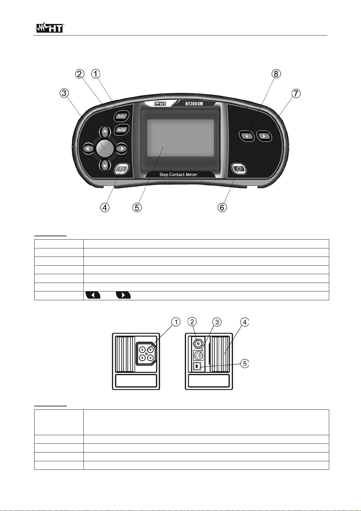
4.2.1 Front view
CAPTION:
1 ESC key to return at previous screen
2 MEM key for access to internal memory (see § 8)
3 , , , arrow keys and TEST key to activation measurements
4 Backlight key
5 LCD display
6 ON/OFF key to switch the instrument ON or OFF
7 - 8
4.2.2 Top view
CAPTION:
Test connector.
1
CAUTION: maximal allowed voltage between test terminals and ground is
50V. Maximal allowed voltage between test terminals is 100V
2 Power supply socket
3 PS/2 connector (for RS232 communication)
4 Protection cover
5 USB connection
Fig. 2: HT2055M unit front view description
and keys for function selection and parameter settings
Fig. 3: HT2055M unit top view description
EN - 7
Page 9
HT2055
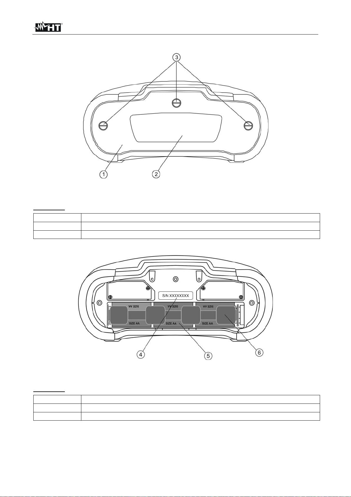
4.2.3 Backside view
Fig. 4: HT2055M unit backside view description
CAPTION:
1 Battery compartment cover
2 Safety information label
3 Fixing screws for battery compartment cover
CAPTION:
4 Serial number label
5 Battery cells (6x1.2V NiMH type AA)
6 Battery compartment
Fig. 5: HT2055M battery compartment description
EN - 8
Page 10

HT2055
5 INITIAL OPERATIONS WITH HT2055M UNIT
Press the or function keys to display the below screens relative to the Step
Voltage, Contact Voltage and Settings (see Fig. 6)
Fig. 6: Screens of general menu
5.1 SETTINGS
The below operations are possible within Settings menu:
Language selection
Help screens on connections
Syncronizing with the station unit HT2055S
Restore of default conditions
Recall at display of saved results (see § 8.2) and clear memory (see § 8.3)
Setting of system time/date
5.1.1 Language selection
Fig. 7: Screen of language selection
1. Press or keys to enter Settings menu
2. Select the item “Select Language” with the or keys and press TEST key
3. Select the desired language with the or keys and confirm with TEST key
4. Press ESC key to exit and go back to the previous screen
5.1.2 Help screen
Fig. 8: Help screen
1. Press or keys to enter Settings menu
2. Select the item “Help” with the or keys and press TEST key
3. Select the desired help screen with the or keys
4. Press ESC key to exit and go back to the previous screen
EN - 9
Page 11

HT2055
5.1.3 Synchronization
Selecting this option will allow to upload different data from the station unit to the meter
unit. The possible options are:
Synchronization of the actual time/date and the generated current
Uploading of test current results for Step / Contact voltage calculation
Uploading of earth resistance and ground resistivity results
Fig. 9: Synchronization screen
1. Press or keys to enter Settings menu
2. Select the item “Synchronize” with the or keys and press TEST key
3. Connect both units by using the PS/2-RS-232 supplied cable
4. Select one of the below options with the or keys and confirm with TEST key
TIME, CURRENT
STEP/CONTACT VOLT
EARTH RESULT
5. Press ESC key to exit and go back to the previous screen
Station’s time and date will be uploaded to the meter. Value
of generator current will be uploaded to the meter
Values of logged generator currents I
will be uploaded to
GEN
the Meter for calculation of Step voltage or Contact voltage
Stored earth resistance or ground resistivity results in the
station will be uploaded to the meter
CAUTION
The main purpose of the Time/ Current synchronization is to enable a
correction of the step and contact voltage results after the test. During the
test the step and contact voltage results are calculated based on the I
set on the meter. After the test the obtained results can be updated with
the real generator currents I
station. The stored U
STEP
measured at the same time with the
GEN
and U
CONTACT
values are then corrected
according to the following formula:
UU
STEPoldSTEPnew
I
SET
I
I
UU
CONToldCONTnew
I
SET
)_(
generatedactuallyGEN
generatedactuallyGEN
)_(
The synchronization is active for 24 h
If date / time are changed on the meter or station the synchronization of
time and date will be lost. The current logger must be cleared before it can
proceed with measurements. Before clearing it you can download its
content to the meter
GEN
EN - 10
Page 12

HT2055
5.1.4 Default settings
This section permits to restore the default value (factory) of measurement parameters and
limits set on the instrument
Fig. 10: Initial settings screen
1. Press or keys to enter Settings menu
2. Select the item “Initial Settings” with the or keys and press TEST key
3. Select the “NO” or “YES” options with the or keys and confirm with TEST
4. Press ESC key to exit and go back to the previous screen
The default values are the following:
Language
Contact and Step voltage
English
I
= 10A
GEN
I
= 1kA
FLT
R
= 1MΩ
INP
U
= 50V
LIM
5.1.5 Time/Date settings
Fig. 11: Time/Date settings screen
1. Press or keys to enter Settings menu
2. Select the item “Set Date/Time” with the or keys and press TEST key
3. Use the ,, and keys to set the date/time and confirm with TEST
4. Press ESC key to exit and go back to the previous screen
5.2 MESSAGES AT DISPLAY
The below messages (icons) can be displayed on the meter unit:
The meter and the station are not synchronized
Measurement is running
Results can be stored
Measurement result is within pre-set limits (PASSED)
Measurement result is out of pre-set limits (FAILED)
EN - 11
Page 13

HT2055
6 INITIAL OPERATIONS WITH HT2055S UNIT
Press the or function keys to display the below screens relative to the
earth/resistivity measurements and Settings (see Fig. 12)
Fig. 12: Screens of general menu
6.1 SETTINGS
The below operations are possible within Settings menu:
Language selection (see § 5.1.1)
Restore of default conditions
Setting power of current generator
Setting of alarm conditions when switching off test current
Recall at display of saved results (see § 8.2) and clear memory (see § 8.3)
Time/date setting (see § 5.1.5)
6.1.1 Default settings
This section permits to restore the default value (factory) of measurement parameters and
limits set on the instrument
Fig. 13: Initial settings screen
1. Press or keys to enter Settings menu
2. Select the item “Initial Settings” with the or keys and press TEST key
3. Select the “NO” or “YES” options with the or keys and confirm with TEST
4. Press ESC key to exit and go back to the previous screen
The default values are the following:
Contrast
Language
Alarm
Power of generator
Distance “a”
50%
English
Disabled
100%
2.0m
EN - 12
Page 14

HT2055
6.1.2 Setting output power
This section permits to set the output power of current generator by selecting the
percentages: 10%, 25%, 50%, 75% and 100%
Fig. 14: Output power generator setting screen
1. Press or keys to enter Settings menu
2. Select the item “Power Range” with the or keys and press TEST key
3. Select the desired percentage with the or keys and confirm with TEST
4. Press ESC key to exit and go back to the previous screen
CAUTION
When the current generator is started the output power is automatically set to
the available maximum value. If the conditions change during the
measurement the generator may switch off. Possible causes for switching off
are:
The output can become overloaded by high external earth currents. In this
case it is recommended to decrease the output power down to 75% or 50%
and restart the generator
The current stopped flowing abruptly. If stop was caused by disconnection
of the leads it is not necessary to lower down the power. The generator can
be restarted.
6.1.3 Setting alarm condition
This section permits to set an acoustic alarm condition when stopping current generation
due to noise effect or unexpected opening of circuit under test
Fig. 15: Alarm condition setting screen
1. Press or keys to enter Settings menu
2. Select the item “Alarm” with the or keys and press TEST key
3. Select the options “ENABLED” or “DISABLED” with the or keys and confirm with
TEST
4. Press ESC key to exit and go back to the previous screen
An active alarm helps to avoid wrong interpretation of the Step and Contact
voltage results. The readings will be close to 0 V if no test current is flowing
CAUTION
EN - 13
Page 15

HT2055
6.2 ADJUST CONTRAST OF DISPLAY
1. Press the key. The following screen is shown:
2. Use the or keys to reduce or increase the contrast percentage of display
3. Press the TEST key to confirm the operation or the ESC key to exit from this function
6.3 HELP SCREENS
1. Pressing screen to display the help screen correspondent to the selected function
2. Use the or keys to select the other help screens
3. Press ESC key to exit and go back to the previous screen
6.4 MESSAGES AT DISPLAY
The below messages/screens can be displayed by the station meter:
Voltage between test terminals C1/H and C2/E is higher than
allowed (>10 V). Disconnect the test leads and check why an
external voltage was detected
During current generation output was overloaded or test current
abruptly fell down. Overload can be caused by high spurious earth
current. In this case it is recommended to decrease the output power
(see § 6.1.2)
Output current is too low (< 0.2A). A too low current can be caused
because of bad connection or high probe resistance
Date / time was changed in the station and consequently the
synchronization between station and meter gets lost. The current
logger must be cleared. Before clearing it its contents can be
downloaded to the meter
Output power is not set to maximum
Measurement is running
Results can be stored
High electrical noise was detected during measurement. Results may be
impaired
High resistance of current (c) and/ or voltage (p) probes. Results may be
impaired
EN - 14
Page 16

HT2055
7 HOW TO PERFORM THE MEASUREMENTS
7.1 THEORY OF STEP/CONTACT VOLTAGE MEASUREMENTS
An earth electrode / grid depleted into ground has a certain resistance, depending on its
size, surface (oxides on the metal surface) and the soil resistivity around the electrode.
The earth resistance is not concentrated in one point but is distributed around the
electrode. Correct connection of exposed conductive parts assures that the voltage on
them stays below dangerous level in case of a fault.
If a fault happens a fault current will flow through the earth electrode. A typical voltage
distribution occurs around the electrode (the “voltage funnel”). The largest part of the
voltage drop is concentrated around the earth electrode. The Fig. 16 shows how fault, step
and contact voltages occur as a result of fault currents flowing through the earth electrode
/ grid in the ground.
Fault currents close to power distribution objects (substations, distribution towers, plants)
can be very high, up to 200 kA. This can result in dangerous step and contact voltages. If
there are underground metal connections (intended or unknown) the voltage funnel can
get atypical forms and high voltages can occur far from the point of failure. Therefore the
voltage distribution in case of a fault around these objects must be carefully analyzed.
Fig. 16: Dangerous voltages on a faulty earth system
The guidelines define limit values of step/contact voltages depending on the time of fault
elimination by the protection devices (typically declared by the Mains Energy provider). If
the value of fault voltage is over this limit it is necessary to verify that the values of
step/contact voltages in some potentially dangerous points of the plants (e.g: access
areas, close to metal structures normally de-energized, gates, safety nets, etc) fall within
standard values.
EN - 15
Page 17

HT2055
7.2 STEP/CONTACT VOLTAGE MEASUREMENT
The measurements of step/contact voltage are performed by a voltmeter with an internal
resistance of 1k simulating the body resistance and with two weight probes of 25 kg
each simulating feet. Alternatively it is possible to use two metal plates instead of
weight probes on the ground where the operator stands.
CAUTION
During the measurement a test current is injected into the earth through an
auxiliary probe. The resistance of the auxiliary probe should be as low as
possible in order to inject a high test current. The resistance can be decreased
by using more probes in parallel or using an auxiliary earth system as
auxiliary probe. A higher injected current improves the immunity against
spurious earth currents.
As the test current is usually only a small fraction of the highest fault current the measured
voltages must be up scaled according to the following equation:
I
Fault
UU
,
MeasuredCS
I
Gen
U
………..calculated step or contact voltage in case of fault current
S,C
U
Measured
I
Fault
I
Gen
….measured voltage during the test
………..maximal earth current in case of a fault
………..injected test current
Installation of station unit
1 Place the station unit close to the earth system under test (distance max. 10m).
Connect the unit at the input terminal C1/H by using the supplied cable
2 Fit the auxiliary metal probe (1m length) on the ground at a distance of at least 5 times
the maximum diagonal of the earth system under test (see Fig. 17). Connect the input
terminal C2/E to the probe by using the 50m long cable (if enough) or use another
customized cable for longer distances. The nature of the measurement method permits
the use of different cables without any resistance compensation. Use also several
probes connected in parallel among them if it is necessary to reduce the contact
resistance on that point.
EN - 16
Page 18

HT2055
Fig. 17: Circuit scheme for step voltage measurement
Fig. 18: Circuit scheme for contact voltage measurement
Generation of test current
3 Switch on the station unit HT2055S
4 Use or keys and select the “CURRENT GEN.” screen (see Fig. 19)
Fig. 19: Test current generation screen
EN - 17
Page 19

HT2055
5 Press TEST key to activate the operation. The value of generated current is displayed.
Check this value.
CAUTION
The output power is set automatically to its available maximum value (see
§ 6.1.2)
Completely unwind measuring cable to avoid affecting test current value
(coil impedance)
Usually the resistance of auxiliary probe can affect the generated test
current. The injected current can be increased by placing more probes in
parallel.
Synchronization between the units before the test (recommended)
Before starting with the step/contact voltage measurements it is recommended to
synchronize the meter and the station units. The synchronization sets the same date and
time in both units. Therefore the measured voltages can be correctly scaled after the
measurements. If the current is generated during the synchronization its value is also sent
to the meter unit (see § 5.1.3)
6 Connect both meter and station units through the PS/2-RS-232 cable supplied as
accessory (see Fig. 20)
Fig. 20: RS-232 connection between units
7 Select the option “Synchronize Time, Current” on the meter unit (see § 5.1.3) and
confirm with TEST key. The messages “Connecting...” and “Synchronizing…” are
displayed.
CAUTION
The measurements can be carried out without synchronization. In this case
the measuring current must be set / changed manually. If the injected current
is changing during the test the I
parameter must be adjusted manually. The
GEN
measurement results cannot be corrected after the measurement.
EN - 18
Page 20

HT2055
Perform step/contact voltage measurements
8 Use or keys and select the CONTACT VOLT or STEP VOLT measurements
on the meter unit
Fig. 21: Screens for step/contact voltage measurements
9 Use ,, and keys and perform the settings of the following test parameters:
Igen
Iflt
Rinp
Ulim
Test current (manual setting considering the range 0.20A ÷ 50A) or
automatically fitted by the station unit during the synchronization
Maximum fault current of earth system (range 10A ÷ 200kA)
Input resistance of the meter unit (1M, 1k)
Limit value for step/contact voltage measurements (range 1V ÷ 10kV)
Iflt Fault current value given by the Mains Energy provider
Rinp Input resistance fixed to 1k for step/contact voltage measurements
Ulim Voltage limit given by Guidelines according to the time of fault elimination by the
protection devices
10 Place and connect the test metal plates to each other where the operator stands, close
to the points where step voltage measurement (see Fig. 17) or contact voltage (see
Fig. 18) is required respecting the necessary distances
11 Connect the metal plates to the meter unit by using the cables supplied
12 Press TEST key on the meter unit and perform the step voltage of the contact voltage
measurements. The following screens are displayed by the meter:
Fig. 22: Screens for results of step/contact voltage measurements
Where:
U calculated step/contact voltage
Um measured step/contact voltage
13 Press MEM key to save the result inside memory (see § 8.1)
EN - 19
Page 21

HT2055
Synchronization between the units after the test (recommended)
If the meter and station units were synchronized during the measurements they should be
synchronized again after completing the tests. In this step the values of generated currents
(measured with the station) are downloaded to the meter so automatically correcting the
measured results previously stored and providing the correct value of step and contact
voltages.
14 Connect both meter and station units through the PS/2-RS-232 cable supplied (see
Fig. 20)
15 Select the option “Synchronize Time, Current” on the meter unit (see § 5.1.3) and
confirm with TEST key. The messages “Connecting...” and “Synchronizing…” are
displayed.
16 The following screens can be displayed by the meter unit during the synchronization
Fig. 23: Example of screens on the synchronization operation
NOT SYNCHRONIZED number of not synchronized results
Synchronization of step/contact voltage results can last up to several 10
seconds. A bargraph is showing the progress.
CAUTION
EN - 20
Page 22

HT2055
7.3 EARTH RESISTANCE MEASUREMENT
The earth resistance measurement is performed by the HT2055S station unit only by using
the standard 3-wire method with two supplied auxiliary probes fitted at adequate distances
from the earth system under test according to the Fig. 24
Fig. 24: Connection of instrument for earth resistance measurement
1 Place the station unit close to the earth system under test (distance max. 10m)
2 Connect the input terminals C2/E and ES to the earth system under test by using the
cables supplied
3 Fit the auxiliary metal probe (1m length) on the ground at a distance of least 5 times
the maximum diagonal of the earth system under test (see Fig. 24). Connect the input
terminal C1/H to the probe by using the 50m long cable supplied (if enough) or use
another customized cable for longer distance. The nature of the measurement method
permits the use of different cables without any resistance compensation. Use also
more probes connected in parallel to each other if it’s necessary to reduce the contact
resistance on that point
4 Fit the auxiliary metal probe (60m length) on the ground at a distance of at least 2.5
times the maximum diagonal of the earth system under test (see Fig. 24). Connect the
input terminal S to the probe by using the 50m long cable supplied (if enough) or use
another customized cable for longer distance. The nature of the measurement method
permits the use of different cables without any resistance compensation. Use also
more probes connected in parallel to each other if it’s necessary to reduce the contact
resistance on that point
CAUTION
For large sized installations, place the ampere metric probe (H) at a distance
equal to the diagonal of the earth installation and the volt metric probe (S) at a
distance equal to about 0.5 times the diagonal of the earth installation. In the
latter case several measurements shall be carried out moving the volt metric
probe back and forth (along the measurement direction) with respect to the
middle point and checking that the result is nearly constant
EN - 21
Page 23

HT2055
5 Use or keys and select the EARTH RE measurement on the station unit. The
following screen is displayed:
Fig. 25: Main screen of earth resistance measurement
6 Press TEST key to perform the measurement. The result is displayed
Fig. 26: Result screen of earth resistance measurement
Where:
R Measured value of earth resistance
Rp Voltage probe resistance (S)
Rc Current probe resistance (H)
CAUTION
When starting test the unit performs a preliminary check of the resistance
values for current probe (Rc) and voltage probe (Rp) stopping the test if
these values are assumed to be too high and giving the following
messages “Rc: >2.0k” and “Rp: >2.0k”. Decrease the value of these
resistance wetting the ground close to the probes and/or connect more
probes in parallel
High noise currents and voltages on earth could affect the measurement
results. In this case the tester displays the ”NOISE” warning
7 Press MEM key to save the result inside memory (see § 8.1)
CAUTION
To view stored earth resistance results on PC they must be downloaded to the
meter unit first. To download the results select earth results from Synchronize
menu (see § 5.1.3). After the results are downloaded the stored data in
the station unit will be automatically deleted
EN - 22
Page 24

HT2055
7.4 GROUND RESISTIVITY MEASUREMENT
For the ground resistivity measurement the test current is injected through two current
probes (C1/H and C2/E). The voltage probes S and ES must be placed between the
current probes (equidistance ‘a’ between probes must be considered). Using different
distances between the test probes means that the material is measured at different
depths. By increasing the distance ‘a’ a deeper layer of ground material is measured (see
Fig. 27)
Fig. 27: Connection of the unit for ground resistance measurement
1 Use or keys and select the EARTH RE measurement on the station unit
2 Use the or keys to select the “EARTH ” measurement. The below screen is
displayed:
Fig. 28: Main screen of ground resistance measurement
3 Use the or keys to select the “a” parameter. Use the or keys to set the value
expressed in meters into the range 0.1 ÷ 30.0 by steps of 0.1m
4 Fit the auxiliary test probes at the same distance “a” set on the station unit and connect
the input terminals C1/H, C2/E (current probes), ES and S (voltage probes) to the earth
system under test by using the cables supplied as accessories (see Fig. 27)
5 Press TEST key to perform the measurement. The result is displayed
Fig. 29: Result screen of ground resistance measurement
Where:
Measured value of ground resistivity
Rp Voltage probe resistance (sum of S+ES)
Rc Current probe resistance (sum of C1/H +C2/E)
EN - 23
Page 25

HT2055
CAUTION
When starting test the unit performs a preliminary check of the resistance
values of current probe (Rc) and voltage probe (Rp) stopping the test if
these values are assumed to be too high and giving the messages “Rc:
>2.0k” and “Rp: >2.0k”. Decrease the resistance value wetting the
ground close to the probes and/or connect more probes in parallel
High noise currents and voltages in earth could affect the measurement
results. In this case the tester displays the ”NOISE” warning
6 Press MEM key to save the result inside memory (see § 8.1)
CAUTION
To view stored ground resistivity results on PC they must be downloaded to
the meter unit first. To download the results select earth results in Synchronize
menu (see § 5.1.3). After the results are downloaded the stored data in
the station unit will be automatically deleted
EN - 24
Page 26

HT2055
t
d
d
8 OPERATION WITH MEMORY
The measurement results, including associated parameters, can be saved inside the
internal memories of station unit and meter unit. In particular:
The step/contact voltage measurements can be saved in the meter unit
The earth resistance/ground resistivity measurements can be saved in the station unit
and then transferred to the meter unit
The values of generated currents are automatically saved in the station unit
The internal memory of both units is divided into 3 levels with max 199 locations each. The
number of measurements which can be saved in a location is only limited by the available
memory
The internal memory (see Fig. 30) includes two types of structures:
The data structure defines the order of the saved results with the division into
“OBJECTS” and “LOCATIONS”
The structure of measurements defines the information on the type and the number
of measurements associated to the selected data structure (Object and Location)
Fig. 30: Structure of internal memory of the meters
This kind of structure permits an easy manipulation of saved data as:
The results are organized and structured into groups
The surfing among the saved results is simplified
The printed report can be created with or without minor modifications after the
downloading to PC
Data structure
RECALL RESULTS
Type of operation inside the memory
OBJECT 001
LOC1 001
Data structure (OBJECT, LOCATIONS)
LOC2 001
s
1
OBJECT 001
LOC1 001
LOC2 001
level OBJECT: defines the default name of the object
which is an associated reference number
n
2
level LOC1: defines the first measurement point which is
associated reference number relative to the saved data
r
3
level LOC2: defines the second measurement point which
is associated reference number relative to the saved data
EN - 25
Page 27

HT2055
Measurement structure
No.: 1
No.: 1 [13]
> No.: 7/7
STEP VOLT
Number of measurements associated to the selected location
Number of measurements in the selected location
[Number of measures in the selected location and sub-locations]
Number of selected test / Number of all results saved in the
selected location
Type of measurement saved in the selected location
8.1 SAVING RESULTS
At the end of a measurement test the result and the parameters can be saved into memory
(the icon is shown in the bottom part of display). For saving result follow the following
steps:
1 Press MEM key on the meter. The herewith screen is displayed:
Fig. 31: Saving results inside memory
2 The “FREE“ message means the percentage value of memory still available for saving
operation
3 Use the or keys to select the type of location (Object / Loc1 / Loc2) and the or
to decrease or increase the numerical marker associated to the location (range 1 ÷
199)
4 Press again MEM key to complete the saving of data or the ESC key to exit without
saving
8.2 RECALL RESULT AT DISPLAY
The recall of result at display can be performed in the following equivalent ways:
By pressing MEM key in any measurement screen of the meter
Selecting the item “MEMORY RECALL RESULTS” in settings menu (see § 5.1)
Fig. 32: Recall results at display
1 Use the or keys to select the type of location (Object / Loc1 / Loc2) and the or
to decrease or increase the numerical marker associated to the location (range 1 ÷
199)
2 Press TEST key to select the number of the desired measurement
3 Press again TEST key for recall at display the result of desired measurement
EN - 26
Page 28

HT2055
8.3 DELETE SAVED RESULTS
The following operations are available:
Deletion of all memory
Deletion of data in single selected locations
Deletion of generated currents (only for station unit)
Deletion of internal memory
1 Selected the item “MEMORY CLEAR ALL MEMORY” inside settings menu (see §
5.1). The following screen is displayed
Fig. 33: Deletion of internal memory
2 Press TEST key to confirm the operation. The message “CLEARING MEMORY” is
displayed
3 Press ESC key to exit without performing any operation
Deletion of single measurement
1 Select the item “MEMORY DELETE RESULTS” inside settings menu (see § 5.1).
The folowing screen is displayed
Fig. 34: Deletion of single measurement
2 Use the or keys to select the type of location (Object / Loc1 / Loc2) and the or
to decrease or increase the numerical marker associated to the location (range 1 ÷
199)
3 Press MEM key. The message “CLEAR RESULTS?” is displayed
4 Press TEST key to confirm the operation or ESC to exit the function
Deletion of generated currents
If the meter and station units are synchronized (see § 5.1.3 and § 7.2) the values of
generated currents are stored (together with time and date) in a separated part of the
station’s memory. For delete this currents on the station unit follow the herewith steps:
1 Select the item “MEMORY CLEAR CURRENT LOG” inside settings menu. The
following screen is displayed
Fig. 35: Delete generated currents
2. Press TEST key to confirm the operation. The message “CLEARING MEMORY” is
displayed or press ESC to exit the function
EN - 27
Page 29

HT2055
9 CONNECTION OF THE INSTRUMENT TO PC
The saved data can be transferred to PC by using the TeraView software provided with
instrument.
TeraView software permits the following operations:
Download data from meter
Define customized settings on the final report
Analyse the results of measurements in numerical and graphical screens
Print the final report
Export the data to text (TXT) format file
MINIMUM SYSTEM REQUIREMENTS
Pentium III – 500MHz
512 MB RAM
100 MB free space on HD
CD-ROM reader
USB/serial port
Video resolution 800x600
Windows systems: Win2k/XP/Vista/Win7 32 bit and 64 bit platforms
9.1 INSTALLATION OF SOFTWARE AND INITIAL CONFIGURATIONS (WIN XP)
1. Close all open applications on the PC
2. Insert the supplied CD-ROM in the PC reader
3. Launch the “TeraView.exe” file included on CD-ROM and follow the steps to correctly
install the TeraView software
4. Switch on the instrument and connect it to the PC by using the supplied USB cable or
the PS/2 – RS-232 serial cable connected to a COM port. The USB port have always
priority
5. Read the “Instal_USB_neutral.pdf” file inside the “Handbook” folder for the installation
of USB driver on the PC
6. Launch the TeraView software
7. Select the command “Config Password…”, type the serial number of meter and the
password (which is indicated on the CD-ROM label) and confirm with “Add” (see Fig.
36)
Fig. 36: Insertion of initial password
EN - 28
Page 30

HT2055
8. Select the “Config COM Port…” command and click on the “AutoFind” button to
start the automatic detection of the instrument (see Fig. 37)
Fig. 37: Connection of the instrument to PC
9. The herewith message means a correct detection of meter by the PC
Fig. 38: Correct detection of instrument
10. In case of meter detection failure by the PC it should be necessary to re-configure the
“virtual” COM serial port associated with the USB driver previously installed. The
TeraView program can detect automatically serial ports from COM1 to COM22. Follow
the following steps to modify the COM associated to USB driver:
Right click of mouse on the “My computer” icon on the PC desktop and selection of
“Properties” item
“Hardware” folder “Device Manager” “Ports (COM & LPT)
Move on the “USB CDC Serial Port Emulation (COMxx)” item right click
“Properties”
Select “Port Settings” “Advanced…”
In the COM Port Number list select a “COMxx” among COM1 and COM22
Confirm all operations, come back to software TeraView and repeat the AutoFind
For any information about the use of TeraView software refer to the help on line of
the program
EN - 29
Page 31

HT2055
10 MAINTENANCE
CAUTION
During use and storage, carefully observe the recommendations listed in
this manual in order to prevent possible damage or dangers during use
Do not use the instrument in environments with high humidity levels or at
high temperatures. Do not directly expose to sunlight. Always turn off the
instrument after use. Never remove the front panel of the instrument. The
instrument don’t need any particular maintenance
10.1 REPLACEMENT AND CHARGING BATTERIES
The instrument is power-supplied through internal rechargeable batteries 6x1.2V NiMH
type AA LR03 which are recharged from the mains by means of a supplied battery
charger. The Fig. 39 – left part - shows the low battery level and the need of a recharging
operation. The symbol of recharging battery is shown in Fig. 39 – right
Fig. 39: Condition of low battery level and recharging
In case of batteries replacement follow the following steps:
CAUTION
Turn the power off and disconnect any measurement accessories or mains
supply cable connected to the instrument before opening the battery cover to
avoid electric shock
1. Remove the three screws (see Fig. 4 – Part 3) and open the battery cover
2. Replace all the batteries with others of the same type respecting the indicated polarity
3. Restore the battery cover
4. Use the appropriate battery disposal methods for your area
10.2 REPLACEMENT FUSES OF HT2055S UNIT
Switch off and disconnect any measurement accessories or mains supply
cable before opening the fuses compartment to avoid electric shock
CAUTION
1. Open the fuses compartment (see Fig. 1 – Part 1) with a screwdriver
2. Extract the red switch (see Fig. 1 – Part 2) from the fuses compartment
3. Extract the damaged fuses in the lateral sides of switch and replace them with others of
the same type (see § 11.1)
4. Restore the switch in the fuses compartment and close it
10.3 CLEANING THE INSTRUMENT
To clean the instrument, use a soft dry cloth. Never use humid cloths, solvents, water, etc.
10.4 END OF LIFE
Warning: the reported symbol indicates that the appliance, the batteries and its
accessories must be disposed of separately and treated correctly.
EN - 30
Page 32

HT2055
11 TECHNICAL SPECIFICATIONS
The accuracy is calculated as [% rdg + (number of dgt) * resolution] at reference condition
indicated in § 11.2
Step/Contact voltage measurement
Measured voltage range Resolution Accuracy
0.01 19.99mV
20.0 199.9mV
200 1999mV
2.00 19.99V
20.0 59.9V
Calculated voltage range Resolution Accuracy
0.0 199.9V
200 999V
(*) The calculated value of step/contact voltage is obtained by the relationship: US=Umis ·Iflt/Igen; UC=Umis ·Iflt/Igen;
Fault current range (selectable): 10A 200kA
Input resistance (selectable): 1k, 1M
Noise reducing: DSP 55Hz filtering, 64dB rejection of 50/60Hz noise
Generated current range Resolution Accuracy
0.00 9.99A
10.0 99.9A
Generated current: 55A max
Test voltage: <55V
Test frequency: 55Hz
Earth resistance measurement
Measurement range Resolution Accuracy
0.001 1.999 0.001
2.00 19.99 0.01
20.0 99.9
100.0 199.9 (5.0rdg)
Open voltage: < 50V AC
Test current: < 7.5A
Frequency of test signal: 55Hz
Influence of probe resistance: ±(10%rdg + 10dgt)
(Rc, Rp)
Automatic test of probe resistance: Yes
Automatic detection of voltage noise
max (10 + 100R) or 2k considering lower value
Ground resistivity measurement
Measurement range Resolution Accuracy
0.00m 9.99m 0.01m
10.0m 99.9m 0.1m
100m 999m 1m
1.00km 9.99km 0.01km
10.0km 99.9km 0.1km
Principle of measure: Wenner method = 2** distance* R
0.01mV
0.1mV
1mV
0.01V
0.1V
0.1V
1V
0.01A
0.1A
0.1
(2.0rdg + 2dgt)
calculated value (*)
(3.0rdg + 5dgt)
(3.0rdg + 3dgt)
(2.0rdg + 5dgt)
Calculated value, considering
accuracy of resistance to earth
function
EN - 31
Page 33

HT2055
11.1 GENERAL CHARACTERISTICS
Station unit HT2055S
Power supply: 110V (±10%) or 230V AC (±10%), 50/60Hz
Max. power consumption: 750VA
Protection on mains: 2x fuse T 6.3A / 500V (5mm x 20mm)
Safety of meter: IEC/EN61010-1
Safety of accessories: IEC/EN61010-031
Installation over 1kVAC: HD 637 S1
Earth/resistivity measurement: ANSI/IEEE Std 81
Italian guideline: CEI 11-1
Spanish guideline: RAT 2008
Insulation: class I
Measurement category: CAT II 300V, CAT IV 50V
Pollution degree: 3
Mechanical protection: IP30
Display: LCD dot matrix (128 x 64) with backlit
Internal memory: 1000 locations
Generated current: saved for min 24h
Communication interface: RS-232 (with meter unit HT2055M)
Dimensions (LxWxH): 563 x 257 x 275mm ; 22 x 10 x 11 inches
Weight (without accessories): 29.5kg ; 60lv
Meter unit HT2055M
Internal power supply: 6x1.2V rechargeable batteries NiMH type AA LR03
6x1.5V alkaline batteries type AA LR03
Battery life (rechargeable): 12 hours (typical)
External power supply: 100-240V AC, 50-60Hz / 12V DC
Safety of meter: IEC/EN61010-1
Safety of accessories: IEC/EN61010-031
Insulation: double insulation
Measurement category: CAT IV 50V
Pollution degree: 2
Mechanical protection: IP40
Display: LCD dot matrix (128 x 64) with backlit
Auto Power OFF: after 15 minutes of idleness (not disabled)
Internal memory: 1500 locations
Communication interface: RS-232 and USB
Dimensions (LxWxH): 230 x 115 x 103mm ; 9 x 5 x 4 inches
Weight (with batteries): 1.3kg ; 3lv
EN - 32
Page 34

HT2055
11.2 ENVIRONMENT
Reference temperature: 10°C ÷ 30°C ; 50°F ÷ 86°F
Reference humidity: 35% ÷ 65%RH
Operating temperature: 0°C ÷ 40°C ; 32°F ÷ 104°F
Operating humidity: <85%HR
Storage temperature: -10°C ÷ 60°C ; 14°F ÷ 140°F
Storage humidity: <80%HR
This instrument complies with the requirements of European Directive on low
voltage 2006/95/EC (LVD) and of Directive EMC 2004/108/EC
11.3 STANDARD ACCESSORIES
Station unit HT2055S
Meter unit HT2055M
Power cord for HT2055S unit
Metal current probe, 1m length
Metal voltage probe, 60cm length
Metal plate (200x100mm), 2 pcs
Test cable black, 50m, 10mm2, with alligator clip, with industrial plug, on wheel
Test cable black, 10m, 10mm2, with alligator clip, with industrial plug
Test cable red, 50m, on wheel
Test cable green, 10m, with alligator clip, on wheel
Test cable red, 1m, with alligator clip
Test cable black, 1.5m
Test cable black, with plug for HT2055M, 2x3m
Alligator clip black, 4 pcs
6 x 1.2V rechargeable batteries NiMH type AA, LR03
External adapter 100-240V AC / 12V DC
USB cable
RS-232 - PS/2 cable
“TeraView” software on CD-ROM
Soft carrying bag, 2 pcs
Belt for use of HT2055M unit on neck
User manual
ISO9000 calibration certificates
Wood carrying case
11.4 OPTIONAL ACCESSORIES
Metal current probe, 1m length
Metal voltage probe, 60cm length
EN - 33
Page 35

HT2055
12 SERVICE
12.1 WARRANTY CONDITIONS
This instrument is warranted against any material or manufacturing defect, in compliance
with the general sales conditions. During the warranty period, defective parts may be
replaced. However, the manufacturer reserves the right to repair or replace the product.
Should the instrument be returned to the After-sales Service or to a Dealer, transport will
be at the Customer's charge. However, shipment will be agreed in advance.
A report will always be enclosed to a shipment, stating the reasons for the product’s return.
Only use original packaging for shipment; any damage due to the use of non-original
packaging material will be charged to the Customer.
The manufacturer declines any responsibility for injury to people or damage to property.
The warranty shall not apply in the following cases:
Repair and/or replacement of accessories and battery (not covered by warranty).
Repairs that may become necessary as a consequence of an incorrect use of the
instrument or due to its use together with non-compatible appliances.
Repairs that may become necessary as a consequence of improper packaging.
Repairs which may become necessary as a consequence of interventions performed
by unauthorized personnel.
Modifications to the instrument performed without the manufacturer’s explicit
authorization.
Use not provided for in the instrument’s specifications or in the instruction manual.
The content of this manual cannot be reproduced in any form without the manufacturer’s
authorization.
Our products are patented and our trademarks are registered. The manufacturer
reserves the right to make changes in the specifications and prices if this is due to
improvements in technology.
12.2 SERVICE
If the instrument does not operate properly, before contacting the After-sales Service,
please check the conditions of battery and cables and replace them, if necessary.
Should the instrument still operate improperly, check that the product is operated
according to the instructions given in this manual.
Should the instrument be returned to the After-sales Service or to a Dealer, transport will
be at the Customer's charge. However, shipment will be agreed in advance.
A report will always be enclosed to a shipment, stating the reasons for the product’s return.
Only use original packaging for shipment; any damage due to the use of non-original
packaging material will be charged to the Customer.
EN - 34
 Loading...