


ENGLISH
User manual
Copyright HT ITALIA 2012 Version EN 1.01 - 19/03/2012

HT701
Table of contents:
1. PRECAUTIONS AND SAFETY MEASURES ............................................................... 2
1.1. Preliminary instructions ..................................................................................................... 2
1.2. During use ......................................................................................................................... 3
1.3. After use ............................................................................................................................ 3
1.4. Definition of measurement (overvoltage) category ............................................................ 3
2. GENERAL DESCRIPTION ........................................................................................... 4
2.1. Measuring average values and TRMS values ................................................................... 4
2.2. Definition of true root mean square value and crest factor ................................................ 4
3. PREPARATION FOR USE ........................................................................................... 5
3.1. Initial checks ...................................................................................................................... 5
3.2. Instrument power supply ................................................................................................... 5
3.3. Calibration ......................................................................................................................... 5
3.4. Storage .............................................................................................................................. 5
4. OPERATING INSTRUCTIONS ..................................................................................... 6
4.1. Instrument description ....................................................................................................... 6
4.2. Description of function keys .............................................................................................. 7
4.2.1. HOLD/LOCK key ................................................................................................................. ....... 7
4.2.2. MAX/MIN/ key .......................................................................................................................... 7
4.2.3. Hz/0/ key ........................................................................................................................... 7
4.2.4. MODE key ...................................................................................................................... ............ 7
4.2.5. STORE/RECALL key .................................................................................................................. 8
4.2.6. RANGE/50V-1kV key ................................................................................................................. 8
4.2.7. TEST key .................................................................................................................................... 8
4.3. Internal modes of the instrument ....................................................................................... 9
4.3.1. Deactivation of the Autobacklight function ................................................................................. 9
4.3.2. Deactivation of the Auto power off function ................................................................................ 9
4.3.3. AutoTest and Manual Test mode ............................................................................................... 9
4.3.4. HFR mode ...................................................................................................................... ............ 9
4.3.5. SMOOTH mode .......................................................................................................................... 9
4.3.6. Integrity test on internal fuse ...................................................................................................... 9
4.4. Measuring operations ...................................................................................................... 10
4.4.1. DC Voltage measurement ........................................................................................................ 10
4.4.2. AC Voltage and Frequency measurement ............................................................................... 11
4.4.3. DC Current measurement ........................................................................................................ 12
4.4.4. AC current and frequency measurement ................................................................................. 13
4.4.5. Resistance measurement and continuity test ........................................................................... 14
4.4.6. Diode test .................................................................................................................................. 15
4.4.7. Capacitance measurement ....................................................................................................... 16
4.4.8. Temperature measurement ...................................................................................................... 17
4.4.9. Insulation resistance measurement .......................................................................................... 18
5. MAINTENANCE ......................................................................................................... 19
5.1. Replacing the batteries and the internal fuse .................................................................. 19
5.2. Cleaning the instrument .................................................................................................. 19
5.3. End of life ........................................................................................................................ 19
6. TECHNICAL SPECIFICATIONS ................................................................................ 20
6.1. Technical characteristics ................................................................................................. 20
6.1.1. Electrical characteristics ........................................................................................................... 23
6.1.2. Considered standards .............................................................................................................. 23
6.1.3. General characteristics ............................................................................................................. 23
6.2. Environment .................................................................................................................... 23
6.2.1. Environmental conditions for use ............................................................................................. 23
6.3. Accessories ..................................................................................................................... 24
6.3.1. Standard accessories ............................................................................................................... 24
6.3.2. Optional accessories ................................................................................................................ 24
7. SERVICE .................................................................................................................... 25
7.1. Warranty conditions ......................................................................................................... 25
7.2. Service ............................................................................................................................ 25
EN - 1
HT701
1. PRECAUTIONS AND SAFETY MEASURES
The instrument has been designed in compliance with directive IEC/EN61010-1 relevant to
electronic measuring instruments. For your safety and in order to prevent damaging the
instrument, please carefully follow the procedures described in this manual and read all
notes preceded by the symbol with the utmost attention. Before and after carrying out
the measurements, carefully observe the following instructions:
Do not carry out any measurement in humid environments.
Do not carry out any measurements in case gas, explosive materials or flammables are
present, or in dusty environments.
Avoid any contact with the circuit being measured if no measurements are being
carried out.
Avoid any contact with exposed metal parts, with unused measuring probes, circuits,
etc.
Do not carry out any measurement in case you find anomalies such as deformation,
breaks, substance leaks, absence of display on the screen, etc.
Pay special attention when measuring voltages higher than 20V, since a risk of
electrical shock exists.
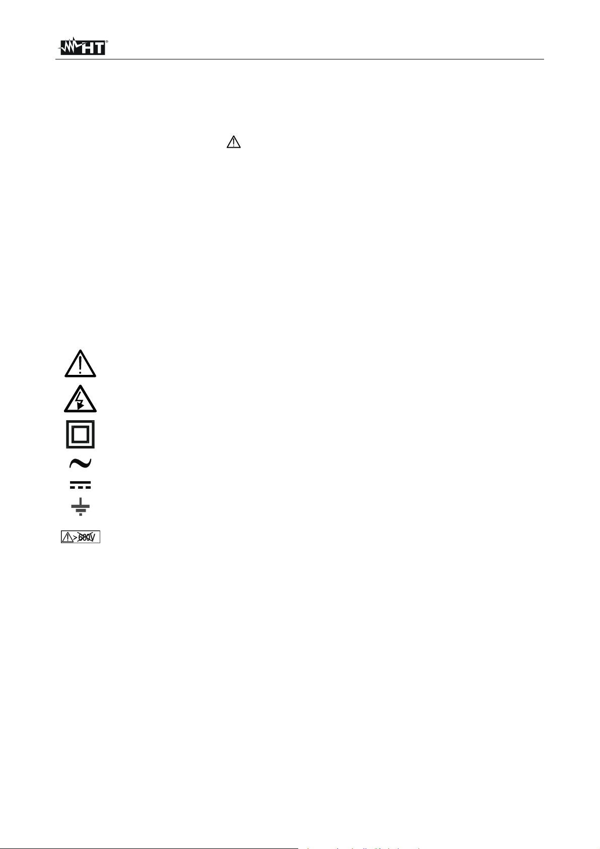
The following symbols are used in this manual:
Caution: observe the instructions given in this manual; an improper use could
damage the instrument or its components
Presence of dangerous voltage ( 30V): electrical shock hazard
Double-insulated meter
AC voltage or current
DC voltage or current
Connection to earth
When measuring insulation, do not apply between input terminals any voltage
higher than 600V DC/ACrms
1.1. PRELIMINARY INSTRUCTIONS
This instrument has been designed for use in environments of pollution degree 2.
It can be used for VOLTAGE and CURRENT measurements on installations with CAT
III 1000V and CAT IV 600V.
Follow the normal safety rules devised to protect the user again st dangerous currents
and the instrument against incorrect use.
Only the leads supplied with the instrument guarantee compliance with the safety
standards. They must be in good conditions and be replaced with identical models,
when necessary.
Do not test circuits exceeding the specified voltage limits.
Do not perform any test under environmental conditions exceeding the limits indicated
in §s 6.1.1 and 6.2.1.
Check that the batteries are correctly inserted.
Before connecting the test leads to the circuit to be test ed, make sure that the switch is
correctly set.
Make sure that the LCD display and the switch indicate the same function.
EN - 2
HT701
1.2. DURING USE
Please carefully read the following recommendations and instructions:
CAUTION
Failure to comply with the Caution notes and/or Instructions may damage
the instrument and/or its components or be a source of danger for the
operator.
Before activating the rotary switch, disconnect the test leads from the circuit under test.
When the instrument is connected to the circuit under test, do not touch any unused
terminal.
Avoid measuring resistance if external voltages are present. Even if the instrument is
protected, excessive voltage could cause a malfunction of the instrument.
While measuring, if the value or the sign of the quantity being measured remain
unchanged, check if the HOLD function is enabled.
1.3. AFTER USE
When measurement is complete, set the rotary switch to OFF to turn off the instrument.
If the instrument is not to be used for a long time, remove the batteries.
1.4. DEFINITION OF MEASUREMENT (OVERVOLTAGE) CATEGORY
Standard “CEI 61010-1: Safety requirements for electrical equipment for measurement,
control and laboratory use, Part 1: General requirements” defines what measurement
category, commonly called overvoltage category, is. § 6.7.4: Measured circuits, reads:
(OMISSIS)
Circuits are divided into the following measurement categories:
Measurement category IV is for measurements performed at the source of the low-
voltage installation
Examples are electricity meters and measurements on primary overcurrent protection
devices and ripple control units.
Measurement category III is for measurements performed on installations inside
buildings.
Examples are measurements on distribution boards, circuit breakers, wiring, including
cables, bus-bars, junction boxes, switches, socket-outlets in the fixed installation, and
equipment for industrial use and some other equipment, for example, stationary motors
with permanent connection to fixed installation.
Measurement category II is for measurements performed on circuits directly
connected to the low-voltage installation.
Examples are measurements on household appliances, portable tools and similar
equipment.
Measurement category I is for measurements performed on circuits not directly
connected to MAINS.
Examples are measurements on circuits not derived from MAINS, and specially
protected (internal) MAINS-derived circuits. In the latter case, transient stresses are
variable; for that reason, the standard requires that the transient withstand capability of
the equipment is made known to the user.
EN - 3

HT701
2. GENERAL DESCRIPTION
Instrument HT701 carries out the following measurements:
DC and AC TRMS voltage
DC and AC TRMS current
Resistance and Continuity test
Insulation resistance with test voltage of 50, 100, 250, 500, 1000VDC
AC voltage and current frequency
Capacity
Diode test
Temperature with K-type probe
Each of these functions can be selected using the 8-position rotary switch, including an
OFF position. The instrument is also equipped with function keys (see § 4.2) and an
analogue graphic bar. The selected quantity appears on the LCD display with the
indication of the measuring unit and of the enabled functions.
The instrument is also equipped with an automatic display backlighting function
(Autobacklight) and with an Auto Power OFF function which automatically switches off the
instrument approx. 20 minutes after the last time a function key was pressed or the rotary
switch was turned. To switch on the instrument again, turn the rotary switch.
2.1. MEASURING AVERAGE VALUES AND TRMS VALUES
Measuring instruments of alternating quantities are divided into two big families:
AVERAGE-VALUE meters: instruments measuring the value of the sole wave at
fundamental frequency (50 or 60 Hz).
TRMS (True Root Mean Square) VALUE meters: instruments measuring the TRMS
value of the quantity being tested.
With a perfectly sinusoidal wave, the two families of instruments provide identical results.
With distorted waves, instead, the rdgs shall differ. Average-value meters provide the RMS
value of the sole fundamental wave; TRSM meters, instead, provide the RMS value of the
whole wave, including harmonics (within the instrument’s bandwidth). Therefore, by
measuring the same quantity with instruments from both families, the values obtained are
identical only if the wave is perfectly sinusoidal. In case it is distorted, TRMS meters shall
provide higher values than the values read by average-value meters.
2.2. DEFINITION OF TRUE ROOT MEAN SQUARE VALUE AND CREST FACTOR
The root mean square value of current is defined as follows: “In a time equal to a period,
an alternating current with a root mean square value with an intensity of 1A, circulating on
a resistor, dissipates the same energy that, during the same time, would have been
dissipated by a direct current with an intensity of 1A”. This definition results in the numeric
expression:
Tt
0
1
G=
T
The Crest Factor is defined as the relationship between the Peak Value of a signal and its
RMS value: CF (G)=
sinusoidal wave it is 2 =1.41. In case of dist ortion, the Crest Factor takes higher values
as wave distortion increases.
2
dttg
)(
t
0
The root mean square value is indicated with the acronym RMS.
G
p
This value changes with the signal waveform, for a purely
G
RMS
EN - 4

HT701
3. PREPARATION FOR USE
3.1. INITIAL CHECKS
Before shipping, the instrument has been checked from an electric as well as mechanical
point of view.
All possible precautions have been taken so that the instrument is delivered undamaged.
However, we recommend generally checking the instrument in order to detect possible
damage suffered during transport. In case anomalies are found, immediately contact the
forwarding agent.
We also recommend checking that the packaging contains all components indicated in §
6.3.1. In case of discrepancy, please contact the Dealer.
In case the instrument should be returned, please follow the instructions given in § 7.
3.2. INSTRUMENT POWER SUPPLY
The instrument is supplied with four 1.5V AA IEC LR6 alkaline batteries, included in the
package.
In order to prevent compromising its charge, the battery is not inserted in the instrument.
For battery installation, follow the instructions given in § 5.1
When the batteries are flat, the symbol “ ” appears on the display. To replace/insert the
batteries, see § 5.1.
3.3. CALIBRATION
The instrument has the technical specifications described in this manual. The instrument’s
performance is guaranteed for 12 months.
3.4. STORAGE
In order to guarantee precise measurement, after a long storage time under extreme
environmental conditions, wait for the instrument to come back to normal condition (see
the environmental specifications contained in § 6.2.1 before use).
EN - 5
HT701
4. OPERATING INSTRUCTIONS
4.1. INSTRUMENT DESCRIPTION
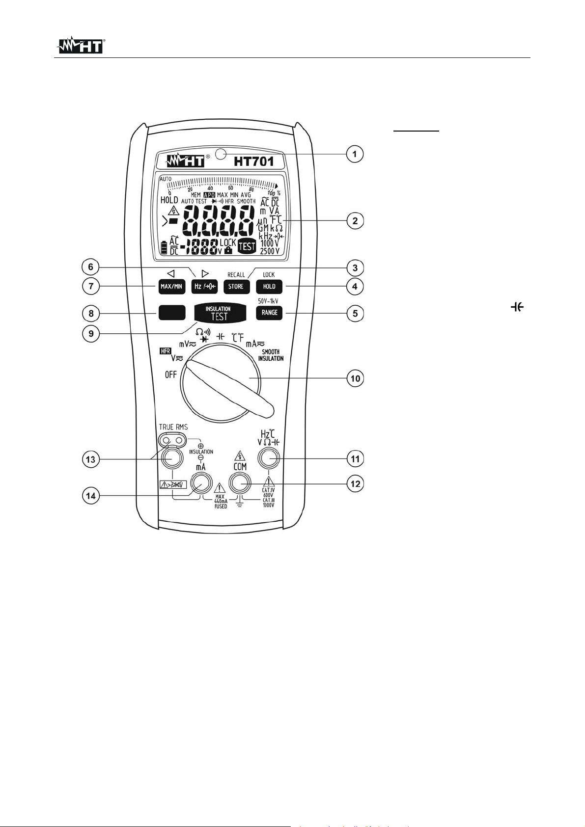
CAPTION:
1. Auto Backlight
2. LCD display
3. STORE/RECALL key
4. HOLD/LOCK key
5. RANGE key
6. Hz/0 key
7. MAX/MIN key
8. MODE key
9. TEST key
10. Rotary selector switch
11. Input terminal Hz°CV
12. Input terminal COM
13. Input terminal
INSULATION
14. Input terminal mA
Fig. 1: Instrument description
EN - 6

HT701
4.2. DESCRIPTION OF FUNCTION KEYS
The following § describes the functions of the different keys. When pressing a key, the
display shows the symbol of the activated function and the buzzer sounds.
4.2.1. HOLD/LOCK key
Pressing the HOLD/LOCK key:
in any function, except for the insulation measurement, keeps the value of the
measured quantity shown on the display. The message “HOLD” appears on the
display. Press the HOLD key again, the MODE key, the RANGE key or turn the rotary
switch to exit the function.
When measuring insulation (see § 4.4.9), pressing the HOLD/LOCK key allows
blocking the test voltage set and carrying out a continuous measurement. The symbols
“ ” and “LOCK” appear on the display. Press the TEST key to exit the function.
4.2.2. MAX/MIN/ key
Pressing the MAX/MIN/ key:
in any function, except for insulation measurement, activates the detection of
Maximum, Minimum and Average (AVG) values of the quantity being tested. Both
values are constantly updated, as soon as the instrument measures a higher (MAX) or
lower (MIN) value. The display shows the symbol associated with the selected function:
“MAX” for maximum value and “MIN” for minimum value. The flashing symbol “MAX
MIN” shows the current value on the display. The symbol “AVG” shows on the display
the value of the average between the maximum and the minimum value currently
shown on the display. Press and hold the MAX/MIN/ key for 2 seconds, the MODE
key, the RANGE key or turn the rotary switch to exit the function.
In “RECALL” function (recalling the data saved in the memory on the display – see §
4.2.5), the key allows selecting the memory cell before the one currently shown on
the display.
4.2.3. Hz/0/ key
Pressing the Hz/0/ key:
in functions “V”, “mV” and “mA” allows selecting voltage or current frequency
measurement. The symbol “Hz” is shown on the display. Press the key again or turn
the rotary switch to exit the function.
In functions “ ” and “” (for values < approx. 3 - e.g.: short-circuited test leads) it
allows measuring the quantity to be tested. The symbol “0” appears on the display,
initially steady. When pressing the key, the symbol “0” flashes and the value of the
quantity being tested is saved as offset for the following measurements. The display
shows the relative value, obtained as: relative value (displayed) = current value –
offset. Press the Hz/0/ key, the MODE key, the RANGE key or turn the rotary
switch to exit the function.
In “RECALL” function (recalling the data saved in the memory on the display – see §
4.2.5), the key allows selecting the memory cell after the one currently shown on the
display.
4.2.4. MODE key
The MODE key allows:
Selecting the functions on the rotary switch, highlighted in orange.
Quitting sub-functions selected on the instrument.
Switching from AutoTest mode to Manual mode (see § 4.3.3).
Deleting the internal memory of the instrument (see § 4.2.5)
EN - 7

HT701
4.2.5. STORE/RECALL key
The STORE/RECALL key carries out the following operations:
Simply pressing the key allows saving the value on the display in the memory. The
symbol “MEM” flashes for a second and the considered memory location is
immediately indicated on the display. Each measuring function has its own dedicated
memory space for a maximum of 100 available locations for each of them.
Pressing and holding the key for 2 seconds allows recalling the data saved in the
internal memory on the display. The symbol “MEM” and the indication of the last
memory location are shown on the display together with the measurement result. Press
the keys or to select the desired memory location. Press and hold the keys or
for 2 seconds to rapidly select the memory locations.
Press and hold the MODE key for 2 seconds to delete the whole instrument memory.
The message “nOnE” is shown on the display and the indication of the memory
location is taken back to “0”. As an alternative, press and hold the STORE/RECALL
key while switching on the instrument.
Press the STORE/RECALL key again or turn the rotary switch to exit the function.
4.2.6. RANGE/50V-1kV key
Pressing the RANGE/50V-1kV key allows the following operations:
Manual selection of the measuring range of the different functions (except for positions
, , °C and °F and insulation measurement). T he symbol “AUTO” disappears from
the display and the cyclic pressure of the key modifies the position of the decimal point
on the display. Press and hold the RANGE key for 2 seconds or turn the rotary switch
to exit the function and restore the symbol “AUTO” on the display.
Selecting t he test voltage in insulation measurement (see § 4.4.9) among the following
values: 50V, 100V, 250V, 500V and 1000VDC. The symbols of the selected voltages
are shown at the bottom of the display on the right.
Quitting sub-functions selected on the instrument.
4.2.7. TEST key
Pressing the TEST key allows activating the insulation resistance measurement on the
instrument (see § 4.4.9).
EN - 8

HT701
4.3. INTERNAL MODES OF THE INSTRUMENT
4.3.1. Deactivation of the Autobacklight function
The instrument has a display backlighting function (see Fig.1 – part 1) which activates
automatically in conditions of poor visibility. The function deactivates automatically after a
few seconds. To manually disable the function, proceed as follows:
1. Switch off the instrument (OFF).
2. Turn the rotary switch in any position, keeping the MAX/MIN key pressed until the
display has completely turned on.
3. Switch off and then on again the instrument to enable the function.
4.3.2. Deactivation of the Auto power off function
In order to preserve internal batteries, the instrument switches automatically off 20 minutes
after it was last used. The symbol “APO” appears on the display when this function is
active. When the instrument must be used for long periods of time, it may be useful to
deactivate the Auto Power Off function as follows:
1. Switch off the instrument (OFF).
2. Turn the rotary switch in any position, keeping the MODE key pressed until the display
has completely turned on. The symbol “APO” disappears.
3. Switch off and then on again the instrument to enable the function.
4.3.3. AutoTest and Manual Test mode
In measuring functions “V”, “mV” and “mA” it is possible to use the following two modes:
AutoTest it allows the automatic detection of AC or DC measurement of voltage or
current. The message “AUTOTEST” is shown on the display. This is the mode set
whenever the instrument is switched on.
Manual Test it allows manually setting the AC or DC measurement of voltage or
current.
Press the MODE key to switch from AutoTest mode to Manual mode. The message
“AUTOTEST” disappears from the display and the modes “DC” or “AC” can be selected by
pressing the MODE key again. Press and hold the MODE key for 2 seconds to go back to
the AutoTest mode, or switch off and then on again the instrument.
4.3.4. HFR mode
In measuring function “V”, when pressing the MODE key in Manual mode, it is possible to
select “HFR” (High Frequency Reject) measurement. In this case, the AC voltage
measurement is carried out considering a maximum signal frequency of 500Hz, and this
allows eliminating different harmonic components from it.
Press the MODE key to exit the “HFR” mode.
4.3.5. SMOOTH mode
In insulation resistance measuring mode, by pressing the MODE key it is possible to select
the “SMOOTH” mode, which enables a greater stability of the result displayed. Press the
MODE key to exit the “SMOOTH” mode.
4.3.6. Integrity test on internal fuse
The instrument allows testing the status of the internal fuse as follows:
1 Insert a test lead into input terminal Hz°CV .
2 Turn the rotary switch to . Press the MODE key to select diode test (symbol
“ ” on the display).
3 Insert the test lead into input mA. With indication of a result typically <2V Fuse OK.
With indication “OL” the fuse must be replaced.
EN - 9

HT701
4.4. MEASURING OPERATIONS
4.4.1. DC Voltage measurement
The maximum input DC voltage is 1000 V. Do not measure voltages
exceeding the limits given in this manual. Exceeding voltage limits could
result in electrical shocks to the user and damage to the instrument.
CAUTION
Fig. 2: Use of the instrument for DC voltage measurement
1. Select positions V
or mV
2. If necessary, press the MODE key for manually selecting DC measurement (see §
4.3.3).
3. Use the RANGE key for manually selecting the measuring range (see § 4.2.6) or use
Autorange selection. If voltage value is unknown, select the highest range
4. Insert the red cable into input lead Hz°CV
and the black cable into input lead COM
5. Position the red lead and the black lead respectively in the points with positive and
negative potential of the circuit to be measured. The display shows the value of
voltage.
6. If the display shows the message “OL”, select a higher range.
7. When symbol “-” appears on the instrument’s display, it means that voltage has the
opposite direction with respect to the connection in Fig. 2
8. For using the HOLD function, see § 4.2.1, for measuring MAX/MIN/AVG values see §
4.2.2 and for saving the result, see § 4.2.5
EN - 10

HT701
4.4.2. AC Voltage and Frequency measurement
CAUTION
The maximum input AC voltage is 1000Vrms. Do not measure voltages
exceeding the limits given in this manual. Exceeding voltage limits could
result in electrical shocks to the user and damage to the instrument.
Fig. 3: Use of the instrument for AC voltage measurement
1. Select positions V or mV
2. If necessary, press the MODE key for manually selecting AC measurement (see §
4.3.3) or HFR measurement (see § 4.3.4).
3. Use the RANGE key for manually selecting the measuring range (see § 4.2.6) or use
Autorange selection. If voltage value is unknown, select the highest range.
4. Insert the red cable into input lead Hz°CV and the black cable into input lead COM
5. Position the red lead and the black lead respectively in the points of the cir cuit to be
measured (see Fig. 3). The display shows the value of voltage.
6. If the display shows the message “OL”, select a higher range.
7. Press the Hz/0 key to display the frequency measure of AC voltage. The symbol
“Hz” is shown on the display.
8. For using the HOLD function, see § 4.2.1, for measuring MAX/MIN/AVG values see §
4.2.2 and for saving the result, see § 4.2.5
EN - 11

HT701
4.4.3. DC Current measurement
The maximum input DC current is 400mA. Do not measure currents
exceeding the limits given in this manual. Exceeding current limits could
result in electrical shocks to the user and damage to the instrument.
CAUTION
Fig. 4: Use of the instrument for DC current measurement
1. Cut off power supply from the circuit to be measured
2. Select the mA position.
3. If necessary, press the MODE key for manually selecting DC measurement (see §
4.3.3).
4. Use the RANGE key for manually selecting the measuring range (see § 4.2.6) or use
Autorange selection. If current value is unknown, select the highest range.
5. Insert the red cable into the input terminal mA and the black cable into the input
terminal COM.
6. Connect the red lead and the black lead in series to the circuit whose current you want
to measure, respecting polarity and current direction (see Fig. 4)
7. Supply the circuit to be measured. The display shows the value of current.
8. If the display shows the message “OL”, the maximum measurable value has been
reached
9. When symbol “-” appears on the instrument’s display, it means that current has the
opposite direction with respect to the connection of Fig. 4
10. For using the HOLD function, see § 4.2.1, for measuring MAX/MIN/AVG values see §
4.2.2 and for saving the result, see § 4.2.5
EN - 12

HT701
4.4.4. AC current and frequency measurement
CAUTION
The maximum input AC current is 400mA. Do not measure currents
exceeding the limits given in this manual. Exceeding current limits could
result in electrical shocks to the user and damage to the instrument.
Fig. 5: Use of the instrument for AC current measurement
1. Cut off power supply from the circuit to be measured.
2. Select the mA
position.
3. If necessary, press the MODE key for manually selecting AC measurement (see §
4.3.3).
4. Use the RANGE key for manually selecting the measuring range (see § 4.2.6) or use
Autorange selection. If current value is unknown, select the highest range.
5. Insert the red cable into the input terminal mA and the black cable into the input
terminal COM
6. Connect the red lead and the black lead in series to the circuit whose current you want
to measure (see Fig. 5)
7. Supply the circuit to be measured. The display shows the value of current.
8. If the display shows the message “OL”, the maximum measurable value has been
reached.
9. Press the Hz/0 key to display the frequency measure of AC current. The symbol
“Hz” is shown on the display.
10. For using the HOLD function, see § 4.2.1, for measuring MAX/MIN/AVG values see §
4.2.2 and for saving the result, see § 4.2.5
EN - 13

HT701
4.4.5. Resistance measurement and continuity test
CAUTION
Before attempting any resistance measurement, cut off power supply from
the circuit to be measured and make sure that all capacitors are discharged,
if present.
Fig. 6: Use of the instrument for resistance measurement and continuity test
1. Select the position. The symbol “M” is shown on the display.
2. Use the RANGE key for manually selecting the measuring range (see § 4.2.6) or use
Autorange selection. If resistance value is unknown, select the highest range.
3. Insert the red cable into input lead Hz°CV
and the black cable into input lead COM
4. Short-circuit the leads and, if necessary, press the Hz/0 key to activate the Relative
measurement (see § 4.2.3). The symbol “0” flashes and the value on the display is
zeroed
5. Position the test leads in the desired points of the circuit to be measured (see Fig. 6).
The display shows the value of resistance
6. If the display shows the message “OL”, select a higher range
7. Press the MODE key to select the Continuity test. The symbol “
” is shown on the
display. Insert the red and black cables as instructed for resistance measurement. The
buzzer activates for resistance values <30
8. For using the HOLD function, see § 4.2. 1, for measuring MAX/MIN/AVG values see §
4.2.2 and for saving the result, see § 4.2.5
EN - 14

HT701
4.4.6. Diode test
Before attempting any diode test, cut off power supply from the circuit to be
measured and make sure that all capacitors are discharged, if present.
CAUTION
Fig. 7: Use of the instrument for diode test
1. Select the
2. Press the MODE key to select the Diode Test. The symbol “
position.
” is shown on the
display.
3. Insert the red cable into input lead Hz°CV and the black cable into input lead COM.
4. Position the leads at the ends of the diode to be tested, respecting the indicated
polarity (see Fig. 7). The value of directly polarized threshold voltage is shown on the
display. For a good P-N junction, the instrument must show a value between 0.4 and
0.9V. If threshold value is equal to 0mV, the P-N junction of the diode is short-circuited.
5. If the instrument shows the message “OL”, the terminals of the diode are reversed with
respect to the indication given of Fig. 7 otherwise, the P-N junction of the diode is
damaged
6. For using the HOLD function, see § 4.2.1, for measuring MAX/MIN/AVG values see §
4.2.2 and for saving the result, see § 4.2.5
EN - 15

HT701
4.4.7. Capacitance measurement
Before carrying out capacitance measurements on circuits or capacitors, cut
off power supply from the circuit being tested and let all capacitance in it be
discharged.
CAUTION
Fig. 8: Use of the instrument for Capacitance measurement
1. Select the position.
2. If necessary, press the Hz/0 key to activate the Relative capacitance
measurement (see § 4.2.3). The symbol “0” flashes and the value on the display
is zeroed.
3. Use the RANGE key for manually selecting the measuring range (see § 4.2.6) or use
Autorange selection. If the value of capacitance is unknown, select the highest range.
4. Insert the red cable into input lead Hz°CV
and the black cable into input lead COM
5. Position the leads at the ends of the capacitor to be tested, respecting, if necessary, the
positive (red cable) and negative (black cable) polarity on the capacitor to be tested (see
Fig. 8). The display shows the value of capacitance.
6. The message “OL” indicates that the value of capacitance exceeds the maximum
measurable value.
7. For using the HOLD function, see § 4.2.1, for measuring MAX/MIN/AVG values see §
4.2.2 and for saving the result, see § 4.2.5
EN - 16

HT701
4.4.8. Temperature measurement
Fig. 9: Use of the instrument for Temperature measurement
1. Select the °C°F position.
2. Press the MODE key to select measurement in °C or °F.
3. Insert the provided adapter into the input terminals Hz°CV and COM, respecting
the red and black colours found on it (see Fig. 9)
4. Connect the provided K-type wire probe or one of the optional probes (see § 6.3.2) to
the instrument by means of the adapter, respecting the positive and negative polarity
on the probe’s plug. The display shows the value of temperature.
5. The message “OL” indicates that the value of temperature exceeds the maximum
measurable value.
6. For using the HOLD function, see § 4.2.1, for measuring MAX/MIN/AVG values see §
4.2.2 and for saving the result, see § 4.2.5
EN - 17

HT701
4.4.9. Insulation resistance measurement
CAUTION
Check that no voltage is present at the ends of the circuit to be tested
before carrying out an insulation measurement.
During the whole test, make sure that the applied voltage cannot be
accessed by third parties and adequately arrange the system by
disconnecting everything that must not be included in the test.
Fig. 10: Use of the instrument for Insulation measurement
1. Select the INSULATION position.
2. Press the RANGE key for manually selecting test voltage (see § 4.2.6).
3. If necessary, press the MODE key for selecting the “SMOOTH” mode (see § 4.3.5).
The message “SMOOTH” is shown on the display.
4. If necessary, press the HOLD/LOCK key for selecting the “LOCK” mode (see § 4.2.1).
The symbols “ ” and “LOCK” appear on the display.
5. Insert the red remote probe into input lead “” and the black cable into input lead “
”
(see Fig. 10).
6. Position the leads at the ends of the circuit to be tested, respecting positive and negative
polarity (see Fig. 10). If necessary, use the alligator clips.
7. Press and hold the TEST key (with “LOCK” function deactivated) on the instrument or
on the remote probe to start measuring. The symbols “TEST” and “
”, further to the
indication of test voltage, are shown on the display. Release the TEST key to stop
measuring. The result, expressed in M, is shown on the display
8. The message “> full scale M” indicates that the measured value exceeds the full
scale relevant to the selected test voltage.
9. To save the result, see § 4.2.5
EN - 18

HT701
5. MAINTENANCE
CAUTION
Only expert and trained technicians should perform maintenance
operations. Before carrying out this operations, make sure you have
disconnected all cables from the input terminals
Do not use the instrument in environments with high humidity levels or
high temperatures. Do not expose to direct sunlight
Always switch off the instrument after use. In case the instrument is not to
be used for a long time, remove the battery to avoid liquid leaks that could
damage the instrument’s internal circuits
5.1. REPLACING THE BATTERIES AND THE INTERNAL FUSE
When the LCD displays the flat battery symbol “ ”, it is necessary to replace the batteries
Fig. 11: Replacing the batteries and the internal fuse
Battery replacement
1. Remove the test leads from the instrument.
2. Remove the fastening screw and remove the battery compartment cover.
3. Remove the batteries and insert the same number of batteries of the same type (see §
6.1.3) respecting the correct polarity, then restore the battery compartment cover (see
Fig. 11). Use the relevant containers for battery disposal.
Fuse replacement (see § 4.3.6)
1. Position the rotary switch to OFF and remove the cables from the input terminals.
2. Remove the fastening screw and remove the battery compartment cover.
3. Remove the damaged fuse, insert a fuse of the same type (see § 6.1.3) and close the
battery compartment again.
5.2. CLEANING THE INSTRUMENT
Use a soft and dry cloth to clean the instrument. Never use wet cloths, solvents, water, etc.
5.3. END OF LIFE
WARNING: the symbol on the instrument indicates that the appliance and its
accessories must be collected separately and correctly disposed of.
EN - 19

HT701
6. TECHNICAL SPECIFICATIONS
6.1. TECHNICAL CHARACTERISTICS
Accuracy is indicated as [% rdg + (number of dgt * resolution)] at 23°C±5°C, <80%RH
DC Voltage
Range Resolution Accuracy Input impedance Overload protection
100.00mV 0.01mV
1000.0mV 0.1mV
10.000V 0.001V
100.00V 0.01V
1000.0V 0.1V
AC TRMS Voltage
Range Resolution
100.00mV 0.01mV
1000.0mV 0.1mV
10.000V 0.001V
100.00V 0.01V
1000.0V 0.1V
(*) In range: 60 Hz ÷ 1kHz
Input impedance: 10M // < 100pF
For non-sinusoidal voltage, consider the following crest factors (CF):
1.4 CF < 2.0 Add 1.0%rdg to accuracy
2.0 CF < 2.5 Add 2.5%rdg to accuracy
2.5 CF 3.0 Add 4.0%rdg to accuracy
AC TRMS Voltage – HFR mode
Range Resolution
10.000V 0.001V
100.00V 0.01V
1000.0V 0.1V
(*) In range: 60 Hz ÷ 500Hz
Input impedance: 10M // < 100pF
Cutting frequency in HFR mode: 1kHz
For non-sinusoidal voltages, add the same errors as AC TRMS voltage
DC Current
Range Resolution Accuracy Overload protection
100.00mA 0.01mA
400.0mA 0.1mA
AC TRMS Current
Range
100.00mA 0.01mA
400.0mA 0.1mA
For non-sinusoidal currents, add the same errors as AC TRMS voltage
(0.08%rdg+3dgt)
(0.08%rdg+2dgt)
Accuracy
(5060Hz)
10M // <100pF
Accuracy
(605KHz)
(0.9%rdg+3dgt)
(0.9%rdg+3dgt)
(1.9%rdg+3dgt)
(1.9%rdg+3dgt) (*)
Accuracy
(5060Hz)
Accuracy
(605KHz)
(0.9%rdg+3dgt) (2.9%rdg+3dgt)
(0.2%rdg + 2dgt)
Resolution
Accuracy
(505kHz)
(1.5%rdg + 2dgt)
1000VDC/ACrms
Overload protection
1000VDC/ACrms
Overload protection
1000VDC/ACrms
max 440mA
Overload protection
max 440mA
EN - 20

HT701
Resistance
Range Resolution Accuracy
1000.0 0.1
10.000k 0.001k
100.00k 0.01k
(0.5%rdg+2dgt)
1000.0k 0.1k
10.000M 0.001M
40.00M 0.01M
Max voltage
open circuit
Approx. 0.25V 1000VDC/ACrms
Overload protection
Continuity test
Range Accuracy Buzzer Open circuit voltage Overload protection
400.0 (0.5%rdg+2dgt) <30
Approx. 1.2V
1000VDC/ACrms
Diode test
2.000V
Range
Accuracy
(0.5%rdg+2dgt)
Test current Open circuit voltage Overload protection
0.6mA 2.5V 1000VDC/ACrms
Frequency of AC Voltage and AC Current
Range Resolution Accuracy
100.00Hz 0.01Hz
1000.0Hz 0.1Hz
10.000kHz 0.001kHz
100.00kHz 0.01kHz
Signal sensitivity for frequency measure
(0.1%rdg+5dgt)
Function Range
10Hz ÷ 10kHz 10kHz ÷ 100kHz
AC mV
100.00mV 15.00mV
1000.0mV 150.0mV
10.000V 1.500V
AC V
100.00V 3V -
1000.0V 30V -
AC mA
100.00mA 15.00mA -
400.0mA 30mA -
Minimum duration
of pulse
10µs
Sensitivity (sinusoidal wavefor m)
Overload protection
1000VDC/ACrms
max 440mA
Capacitance
Range Resolution Accuracy Measuring time Overload protection
10.000nF 0.001nF
100.00nF 0.01nF
1000.0nF 0.1nF
10.000F 0.001F
100.00F 0.01F
1000.0F 0.1F
10.000mF 0.001mF
40.00mF 0.01mF
(1.2%rdg+80dgt)
(1.2%rdg+20dgt)
(1.2%rdg+2dgt)
(1.2%rdg+20dgt)
(1.2%rdg+80dgt)
0.7s
1000VDC/ACrms
3.75s
7.5s
EN - 21

HT701
Temperature with K probe
Range Resolution Accuracy Overload protection
-200.0°C ÷ 0.0°C
0.0°C ÷ 1200.0°C
-328.0°F ÷ 32.0°F
32.0°F ÷ 2192.0°F
0.1°C
0.1°F
(1.0%rdg+2°C)
(1.0%rdg+1°C)
(1.0%rdg+36°F)
(1.0%rdg+18°F)
1000VDC/ACrms
Insulation resistance
Test voltage Measuring range Accuracy Overload protection
2.000M
50V DC
100V DC
250V DC
500V DC
1000V DC
Test voltage accuracy: +20%rdg, -0%rdg
Short-circuit current: 1mA
Minimum resistance (@ nominal current 1mA): 50k (50V), 100k (100V), 250k (250V), 500k (500V), 1M (1000V)
Discharge time of measured object: <1s (C 1µF)
Maximum capacitive load: 1µF
Voltage detection on circuit: test inhibited for voltages 30V AC/DC on inputs
20.00M
55.0M
2.000M
20.00M
110.0M
2.000M
20.00M
200.0M
275M
2.000M
20.00M
200.0M
550M
2.000M
20.00M
200.0M
2000M
22.0G (10%rdg+3dgt)
(1.5%rdg+5dgt)
600VDC/ACrms
EN - 22

HT701
6.1.1. Electrical characteristics
Conversion: TRMS
Sampling frequency: 3 times per second
Temperature coefficient: 0.15x(accuracy) /°C, <18°C or >28°C
NMRR Normal Mode Rejection Ratio: > 50dB for DC quantities and 50/60Hz
CMRR Common Mode Rejection Ratio: >100dB from DC up to 60Hz (DCV)
> 60dB from DC, up to 60Hz (ACV)
6.1.2. Considered standards
Safety: IEC/EN 61010-1
IEC/EN61557-1, IEC/EN61557-2
Insulation: double insulation
Pollution level: 2
Overvoltage category: CAT IV 600V, CAT III 1000V
Max operating altitude: 2000m (6561ft)
6.1.3. General characteristics
Mechanical characteristics
Size (with shell): 207 (L) x 95 (W) x 52 (H) mm (8 x 4 x 2 inch)
Weight (batteries included): 630g (22 ounces)
Power supply
Battery type: 4 x 1.5V alkaline type AA IEC LR6
Low battery indication: symbol “ ” with battery voltage < approx. 4.8V
Battery life: approx. 80 hours
600 insulation test with new batteries at room
temperature (1M @ 1kV, duty cycle of 5s on
and 25s off)
Auto Power Off after 20 minutes of idleness (disabled)
Memory
Characteristics: max. 100 locations for each function
Display
Characteristics: 5 LCD, 10000 points, decimal sign, analogue
bargraph and autobacklight
Over range indication: “OL” or “-OL”
6.2. ENVIRONMENT
6.2.1. Environmental conditions for use
Reference temperature: 23° ± 5°C (73 ± 41°F)
Operating temperature: 0° ÷ 50°C (32° ÷ 122°F)
Allowable relative humidity: <80%RH
Storage temperature: -20° ÷ 60°C (-4 ÷ 140°F) (batteries not fitted)
Storage humidity: <80%RH (batteries not fitted)
This instrument satisfies the requirements of Low Voltage Directive 2006/95/EC
(LVD) and of EMC Directive 2004/108/EC
EN - 23

HT701
6.3. ACCESSORIES
6.3.1. Standard accessories
Pair of test leads
Pair of alligator clips
Remote probe for insulation measurement
K-type wire probe + adapter
Belt with magnetic end for fastening to metal surfaces
Protection holster
Batteries (not inserted)
User manual
6.3.2. Optional accessories
Couple of test leads Cod. 4413-2
K-type probe for air and gas temperature Cod. TK107
K-type probe for semisolid substance temperature Cod. TK108
K-type probe for liquid substance temperature Cod. TK109
K-type probe for surface temperature Cod. TK110
K-type probe for surface temperature with 90° tip Cod. TK111
EN - 24

HT701
7. SERVICE
7.1. WARRANTY CONDITIONS
This instrument is warranted against any material or manufacturing defect, in compliance
with the general sales conditions. During the warranty period, defective parts may be
replaced. However, the manufacturer reserves the right to repair or replace the product.
Should the instrument be returned to the After-sales Service or to a Dealer, transport will
be at the Customer’s charge. However, shipment will be agreed in advance.
A report will always be enclosed to a shipment, stating the reasons for the product’s return.
Only use original packaging for shipment; any damage due to the use of non-original
packaging material will be charged to the Customer.
The manufacturer declines any responsibility for injury to people or damage to property.
The warranty shall not apply in the following cases:
Repair and/or replacement of accessories and battery (not covered by warranty).
Repairs that may become necessary as a consequence of an incorrect use of the
instrument or due to its use together with non-compatible appliances.
Repairs that may become necessary as a consequence of improper packaging.
Repairs which may become necessary as a consequence of interventions performed
by unauthorized personnel.
Modifications to the instrument performed without the manufacturer’s explicit
authorization.
Use not provided for in the instrument’s specifications or in the instruction manual.
The content of this manual cannot be reproduced in any form without the manufacturer’s
authorization.
Our products are patented and our trademarks are registered. The manufacturer
reserves the right to make changes in the specifications and prices if this is due to
improvements in technology.
7.2. SERVICE
If the instrument does not operate properly, before contacting the After-sales Service,
please check the conditions of batteries and cables and replace them, if necessary.
Should the instrument still operate improperly, check that the product is operated
according to the instructions given in this manual.
Should the instrument be returned to the After-sales Service or to a Dealer, transport will
be at the Customer’s charge. However, shipment will be agreed in advance.
A report will always be enclosed to a shipment, stating the reasons for the product’s return.
Only use original packaging for shipment; any damage due to the use of non-original
packaging material will be charged to the Customer.
EN - 25
 Loading...