

Page 1
A
A
•
A
A
A
A
ITA
HT603
MANUALE D’USO
© Copyright HT ITALIA 2011 Versione IT 1.01 - 19/12/2011
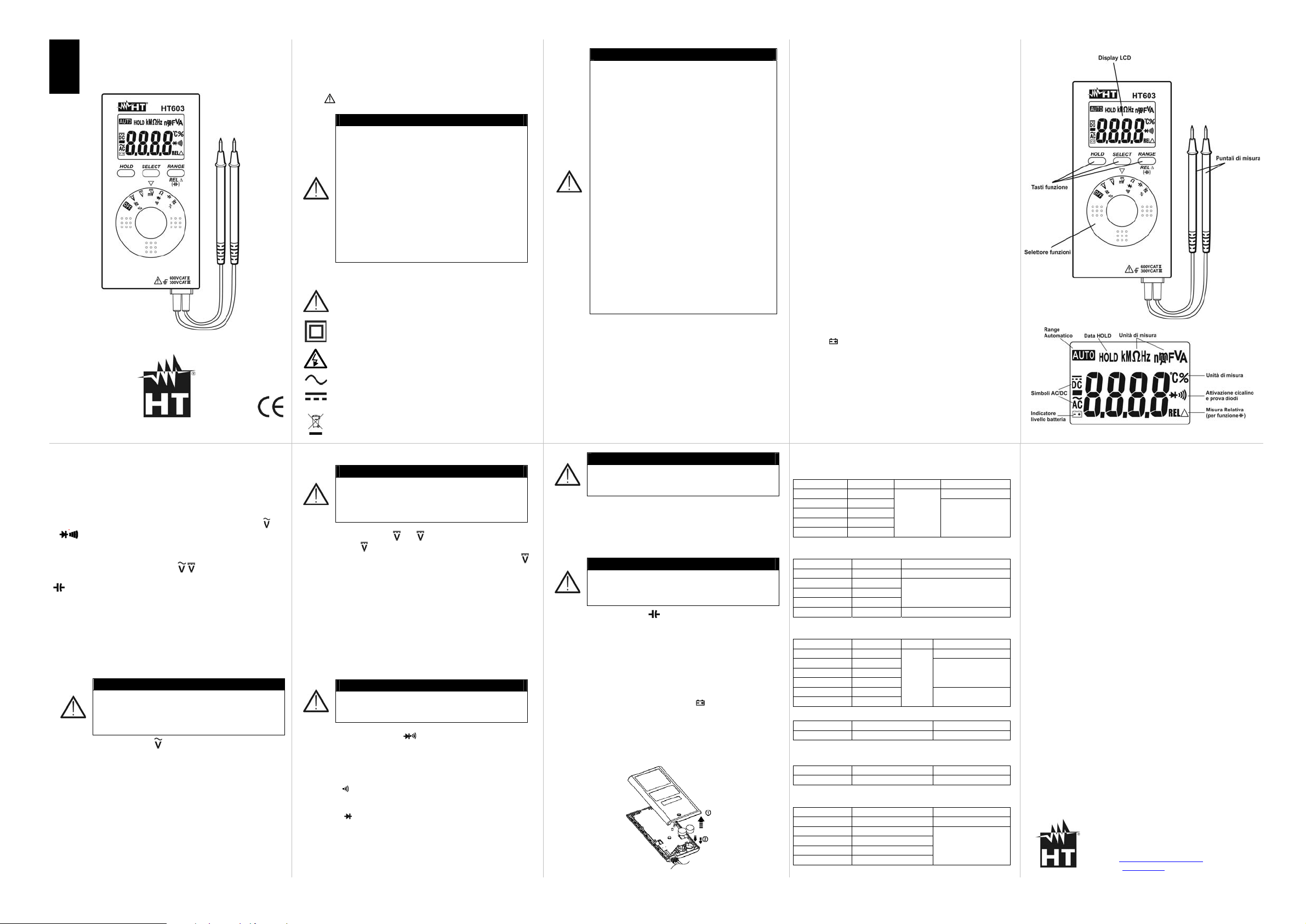
5. DESCRIZIONE DEI TASTI FUNZIONE
5.1 Tasto HOLD
La pressione del tasto HOLD attiva il mantenimento del valore della
grandezza visualizzata a display. Conseguentemente alla pressione
di tale tasto la scritta "HOLD" appare a display. Premere
nuovamente il tasto HOLD per uscire dalla funzione
5.2 Tasto SELECT
La pressione ripetuta del tasto SELECT permette di selezionare le
sotto-funzioni corrispondenti alle posizioni del selettore
Ω
e Hz%
5.3 Tasto RANGE / REL∆
Premere il tasto RANGE/REL∆ per attivare il cambio portata
manuale sullo strumento (funzioni
, e Ω) spegnendo la scritta
"AUTO" a display. Premere il tasto RANGE/ REL∆ (solo funzione
) per attivare la misura relativa. Lo strumento mostra il simbolo
“REL ∆” e azzera il valore a display. Premere ancora il tasto per
uscire dalla funzione
5.4 Disabilitazione Auto Power OFF
Per la disabilitazione della funzione Auto Power OFF:
1. Spegnere lo strumento (OFF)
2. Accendere lo strumento tenendo premuto il tasto RANGE
6. ESECUZIONE DELLE MISURE
6.1 Misura di Tensione AC, Frequenza e Duty Cycle
ATTENZIONE
La massima tensione AC in ingresso è 600V. Non
misurare tensioni che eccedano i limiti indicati in
questo manuale. Il superamento di tali limiti potrebbe
causare shock elettrici all’utilizzatore e danni allo
strumento
1. Selezionare la posizione Hz%. I simboli “AC” e “AUTO” sono
presenti a display. Premere il tasto SELECT per la selezione
della misura di tensione AC (simbolo “V” a display) e il tasto
RANGE per la selezione del campo manuale (vedere § 5.3)
2. Posizionare il puntale rosso ed il puntale nero sul circuito in
esame. Il valore della tensione AC è mostrato a display
3. Il messaggio "OL." indica che il valore di tensione eccede il
valore massimo misurabile
4. Premere il tasto SELECT per la visualizzazione del valore della
frequenza. Il simbolo “Hz” è mostrato a display
5. Premere il tasto SELECT per la visualizzazione del valore del
Duty Cycle (ciclo di lavoro). Il simbolo “%” è mostrato a display
6. Per l’uso della funzione Data HOLD vedere il § 5.1
Hz%,
1. PRECAUZIONI E MISURE DI SICUREZZA
Lo strumento è stato progettato in conformità alla direttiva
IEC/EN61010-1, relativa agli strumenti di misura elettronici. Per la
Sua sicurezza e per evitare di danneggiare lo strumento, La
preghiamo di seguire le procedure descritte nel presente manuale e
di leggere con particolare attenzione tutte le note precedute dal
simbolo
TTENZIONE
• Non effettuare misure in ambienti umidi
• Non effettuare misure in presenza di gas o
materiali esplosivi, combustibili o in ambienti
polverosi
• Evitare contatti con il circuito in esame se non
si stanno effettuando misure
• Evitare contatti con parti metalliche esposte,
con terminali di misura inutilizzati, circuiti, ecc
• Non effettuare alcuna misura qualora si
riscontrino anomalie nello strumento come,
deformazioni, rotture, fuoriuscite di sostanze,
assenza di visualizzazione sul display, ecc
• Prestare particolare attenzione quando si
effettuano misure di tensioni superiori a 20V in
Nel presente manuale e sullo strumento sono utilizzati i seguenti
simboli:
quanto è presente il rischio di shock elettrici
Attenzione: attenersi alle istruzioni riportate nel
manuale; un uso improprio potrebbe causare danni
allo strumento o ai suoi componenti.
Strumento con doppio isolamento
Pericolo Alta Tensione. Rischio di shock elettrici
Tensione AC
Tensione DC
ATTENZIONE: il simbolo riportato sullo strumento
indica che l'apparecchiatura, i suoi accessori e le
batterie devono essere raccolti separatamente e
6.2. Misura di Tensione DC
trattati in modo corretto
TTENZIONE
La massima tensione DC in ingresso è 600V. Non
misurare tensioni che eccedano i limiti indicati in
questo manuale. Il superamento di tali limiti potrebbe
causare shock elettrici all’utilizzatore e danni allo
strumento
1. Selezionare le posizioni
“AUTO” (solo
RANGE per la selezione del campo di misura manuale (solo
o m del selettore . I simboli “DC” e
) sono presenti a display. Premere il tasto
)
(vedere § 5.3)
2. Posizionare il puntale rosso (polarità positiva) ed il puntale nero
(polarità negativa) sul circuito in esame. Il valore della tensione
DC è mostrato a display
3. La visualizzazione del simbolo "-" sul display dello strumento
indica che la tensione ha verso opposto rispetto al collegamento
eseguito
4. Il messaggio "OL." indica che il valore di tensione eccede il
valore massimo misurabile
5. Per l’uso della funzione Data HOLD vedere il § 5.1
6.3 Misura di Resistenza, Test Continuità e Prova Diodi
TTENZIONE
Prima di effettuare qualunque misura di resistenza
accertarsi che il circuito in esame non sia alimentato e
che eventuali condensatori presenti siano scarichi
1. Selezionare la posizione Ω
sono presenti a display. Premere il tasto RANGE per la selezione
del campo di misura manuale (vedere § 5.3)
2. Posizionare i puntali nei punti desiderati del circuito in esame. Il
valore della resistenza è visualizzato a display
3. Premere il tasto SELECT per la selezione del Test Continuità
(simbolo “
” a display). Il cicalino suona per valori di resistenza
<50Ω
4. Premere il tasto SELECT per la selezione della Prova Diodi
(simbolo “
” a display). Collegare il puntale di misura rosso
all’anodo del diodo ed il puntale nero al catodo. La tensione di
polarizzazione diretta, tipicamente 0.4 ~ 0.9V è mostrata a
display. Invertire le connessioni sul diodo. Un risultato “OL.” a
display indica il corretto funzionamento della giunzione
. I simboli “MΩ” “O.L” e “AUTO”
1.1 Istruzioni preliminari
TTENZIONE
Questo strumento è stato progettato per un
utilizzo in un ambiente con livello di
inquinamento 2
• Può essere utilizzato per misure di TENSIONE
su installazioni in CAT III 300V e CAT II 600V
• Solo i puntali forniti a corredo dello strumento
garantiscono gli standard di sicurezza. Essi
devono essere in buone condizioni e sostituiti,
se necessario, con modelli identici
• Non effettuare misure su circuiti che superano i
limiti di tensione specificati
• Non effettuare misure in condizione ambientali
al di fuori delle limitazioni indicate nel § 8
• Controllare se le batterie sono inserite
correttamente
• Prima di collegare i puntali al circuito in esame,
controllare che il selettore sia posizionato
correttamente
• Controllare che il display LCD e il selettore
indichino la stessa funzione
• Prima di azionare il selettore, scollegare i
puntali di misura dal circuito in esame
• Quando lo strumento è connesso al circuito in
esame non toccare mai un qualunque
terminale inutilizzato
• Se, durante una misura, il valore o il segno
della grandezza in esame rimangono costanti
1.2 Definizione di categoria di sovratensione
controllare se è attivata la funzione HOLD
In accordo alla norma IEC/EN61010-1 i circuiti sono suddivisi nelle
seguenti categorie di misura:
• La CAT IV serve per le misure effettuate su una sorgente di
un’installazione a bassa tensione
• La CAT III serve per le misure effettuate in installazioni all’interno
di edifici
• La CAT II serve per le misure effettuate su circuiti collegati
direttamente all’installazione a bassa tensione
• La CAT I serve per le misure effettuate su circuiti non collegati
direttamente alla RETE DI DISTRIBUZIONE
6.4 Misura di Frequenza e Duty Cycle
TTENZIONE
Non eseguire misure su circuiti con tensione
maggiore di 600V AC/DC al fine di evitare shock
1. Selezionare la posizione Hz%. Premere il tasto SELECT per la
elettrici e possibili danni allo strumento
selezione della misura di frequenza o Duty Cycle. I simboli “Hz” o
“%” sono presenti a display. Posizionare i puntali nei punti
desiderati del circuito in esame. Il valore della frequenza (in kHz o
MHz) oppure il valore percentuale è mostrato a display
6.5 Misura di Capacità
TTENZIONE
Prima di eseguire misure di capacità su circuiti o
condensatori, rimuovere l’alimentazione al circuito
sotto esame e lasciare scaricare tutte le capacità
1. Selezionare la posizione ” ”. Premere il tasto RANGE/REL∆ nel
2. Posizionare i puntali ai capi del condensatore in esame rispettando
3. Il messaggio "OL." indica che il valore di capacità eccede il valore
7. SOSTITUZIONE BATTERIE
Quando sul display appare il simbolo "
batterie operando nel modo seguente:
1. Spegnere lo strumento con il tasto OFF
2. Svitare la vite di fissaggio del vano batteria e rimuoverlo
3. Rimuovere le batterie e sostituirle con altre dello stesso tipo
4. Riposizionare il coperchio del vano batteria
presenti in esso
caso di misura di capacità in “nF”. Il valore si azzera a display
eventualmente le polarità positive (cavo rosso) e negative (cavo nero)
sul condensatore in esame. Il valore della capacità è mostrato a
display
massimo misurabile
" occorre sostituire le
2. DESCRIZIONE GENERALE
Lo strumento HT603 esegue le seguenti misure:
• Tensione DC e AC
• Resistenza e Test Continuità
• Frequenza e Duty Cycle (ciclo di lavoro)
• Capacità
• Prova diodi
Ciascuna di queste funzioni può essere selezionata tramite un
selettore a 7 posizioni. Sono inoltre presenti i tasti funzione
HOLD, SELECT e RANGE/REL∆ (vedere § 5.1, § 5.2 e § 5.3).
La grandezza selezionata appare sul display LCD con indicazioni
dell’unità di misura e delle funzioni abilitate. Lo strumento è
inoltre dotato di un dispositivo di Auto Power OFF che provvede a
spegnere automaticamente lo strumento trascorsi 30 minuti
dall'ultima pressione dei tasti funzione o rotazione del selettore
3. PREPARAZIONE ALL’UTILIZZO
3.1 Controlli iniziali
Lo strumento, prima di essere spedito, è stato controllato dal
punto di vista elettrico e meccanico. Sono state prese tutte le
precauzioni possibili affinché lo strumento potesse essere
consegnato senza danni. Tuttavia si consiglia, comunque, di
controllare sommariamente lo strumento per accertare eventuali
danni subiti durante il trasporto. Se si dovessero riscontrare
anomalie contattare immediatamente lo spedizioniere. Si
consiglia inoltre di controllare che l’imballaggio contenga tutte le
parti indicate al § 8. In caso di discrepanze contattare il
rivenditore. Qualora fosse necessario restituire lo strumento, si
prega di seguire le istruzioni riportate al § 9
3.2 Alimentazione dello strumento
Lo strumento è alimentato tramite 2x1.5V batterie tipo LR44
inserite nello strumento. Quando la batteria è scarica appare il
simbolo "
riportate al §7
3.3 Taratura
". Per sostituire la batteria seguire le istruzioni
Lo strumento rispecchia le caratteristiche tecniche riportate nel
presente manuale. Le prestazioni dello strumento sono garantite
per un anno
3.4 Conservazione
Per garantire misure precise, dopo un lungo periodo di
immagazzinamento in condizioni ambientali estreme, attendere
che lo strumento ritorni alle condizioni normali (vedere le
specifiche ambientali elencate al § 8
8. SPECIFICHE TECNICHE
Incertezza riferita a 23°C± 5°C, <80%RH
Tensione AC
Campo misura Risoluzione Frequenza Incertezza
400.0mV 0.1mV
4.000V 0.001V
40.00V 0.01V
400.0V 0.1V
600V 1V
Impedenza di ingresso: 10MΩ, <100pF; Prot. da sovraccarichi: 600V rms
Tensione DC
Campo misura Risoluzione Incertezza
400.0mV 0.1mV
4.000V 0.001V
40.00V 0.01V
400.0V 0.1V
600V 1V
Impedenza di ingresso: 10MΩ, <100pF; Prot. sovraccarichi: 600V rms
Resistenza e Test Continuità
Campo misura Risoluzione Buzzer Incertezza
400.0Ω 0.1Ω
4.000kΩ 0.001kΩ
400.0kΩ 0.1kΩ
4.000MΩ 0.001MΩ
40.00MΩ 0.01MΩ
50 ÷ 500Hz
<50Ω
(campo
400Ω)
Frequenza
Campo misura Risoluzione Incertezza
0.001Hz ÷5MHz
Sensibilità: 1.0Vp-p (Onda quadra) ; Vmax: 5.0Vp-p, 240V (50/60Hz)
Duty Cycle
Campo misura Risoluzione Incertezza
0.1% ÷ 99.9% 0.1%
Sensibilità: 1.0Vp-p 30% ≤Duty≤70% (Onda quadra) ; Vmax: 5.0Vp-p
Capacità
Campo misura Risoluzione Incertezza
50.00nF 0.01nF
500.0nF 0.1nF
5.000µF 0.001µF
50.00µF 0.01µF
100.0µF 0.1µF
0.001Hz ÷ 0.001MHz ±(0.3%lettura+5cifre)
±(1.5%lettura+5cifre)
±(0.9%lettura+5cifre)
±(0.7%lettura+5cifre)
±(0.6%lettura+2cifre)
±(0.7%lettura+5cifre)
±(0.9%lettura+5cifre)
±(0.9%lettura+2cifre) 40.00kΩ 0.01kΩ
±(1.5%lettura+5cifre)
±(0.5%lettura+3cifre)
±(5.0%lettura+0.2nF)
±(2.9%lettura+5cifre)
4. DESCRIZIONE DELLO STRUMENTO E DEL DISPLAY
Sicurezza: IEC/EN61010-1
Categoria di misura: CAT III 300V, CAT II 600V, Grado di inquinamento: 2
Isolamento: doppio isolamento
Conformità a direttiva 2004/108/CE (EMC) e 2006/95/CE (LVD)
Display: LCD, 4 cifre, 5000 punti
Frequenza di campionamento: 3 volte/s
Prova diodi: corrente prova 1.1mA, tensione a vuoto: 1.5VDC (max)
Indicazione fuori scala: simboli “OL.” o “-OL.” a display
Alimentazione: 2x1.5V batterie tipo LR44
Auto Power OFF: dopo 30 minuti di non utilizzo
Temperatura di riferimento: 23°C± 5°C; <80%RH
Temp. lavoro: 0 ÷30°C <80%RH ; 30 ÷40°C <75%RH ; 40 ÷50°C <45%RH
Temperatura di conservazione: -20 ÷ 60°C ; <80%RH
Max altitudine di utilizzo: 2000m
Dimensioni (LxLaxH): 112x56x12mm
Peso (con batterie): 115g
Accessori in dotazione: puntali, batterie (inserite), manuale d’uso
9. ASSISTENZA
9.1 Condizioni di garanzia
Questo strumento è garantito contro ogni difetto di materiale e
fabbricazione, in conformità con le condizioni generali di vendita.
Durante il periodo di garanzia, le parti difettose possono essere
sostituite, ma il costruttore si riserva il diritto di riparare ovvero
sostituire il prodotto.
Qualora lo strumento debba essere restituito al servizio post vendita o ad un rivenditore, il trasporto è a carico del Cliente. La
spedizione dovrà, in ogni caso, essere preventivamente concordata.
Allegata alla spedizione deve essere sempre inserita una nota
esplicativa circa le motivazioni dell’invio dello strumento.
9.2 Assistenza
Se lo strumento non funziona correttamente, prima di contattare il
Servizio di Assistenza, controllare lo stato della batteria e dei cavi e
sostituirli se necessario. Se lo strumento continua a manifestare
malfunzionamenti controllare se la procedura di utilizzo dello stesso
è conforme a quanto indicato nel presente manuale. Qualora lo
strumento debba essere restituito al servizio post - vendita o ad un
rivenditore, il trasporto è a carico del Cliente. La spedizione dovrà, in
ogni caso, essere preventivamente concordata. Allegata alla
spedizione deve essere sempre inserita una nota esplicativa circa le
motivazioni dell’invio dello strumento. Per la spedizione utilizzare
solo l’imballaggio originale; ogni danno causato dall’utilizzo di
imballaggi non originali verrà addebitato al Cliente.
HT ITALIA SRL
Via della Boaria, 40
48018 – Faenza (RA) – ITALY
Tel: +39-0546-621002
Fax: +39-0546-621144
Web: www.ht-instruments.com
Email: ht@htitalia.it
Page 2
•
ENG
HT603
USER MANUAL
© Copyright HT ITALIA 2011 Release EN 1.01 - 19/12/2011
5. FUNCTION KEYS DESCRIPTION
5.1 HOLD key
By pressing HOLD key the measured value is hold on the display
where the symbol "HOLD" appear. Pressing again HOLD to disable
this function and resume normal operation
5.2 SELECT key
Press SELECT key to select the sub-functions relative to the
Ω
and Hz% posiction of rotary switch
5.3 RANGE/REL∆ key
By pushing RANGE/REL∆ key the manual mode is activated
(functions
RANGE/REL∆ key (only function
, and Ω) and the “AUTO” symbol disappears. Press
) to enable relative
measurement. The “REL ∆” symbol is shown and the value is zeroed
at display. Press again the key to exit from the function
5.4 Disable Auto Power OFF
For the disable of Auto Power OFF feature:
1. Switch off the instrument
2. Switch on the instrument by press and hold RANGE key
6. HOW TO PERFORM THE MEASUREMENTS
6.1 AC Voltage, Frequency and Duty Cycle measurements
CAUTION
Maximum input for AC voltage measurements is
600V. Do not take any voltage measurement
exceeding this limit in order not to risk electrical shock
or damaging the meter
1. Rotate the selector on Hz% position. The “AC” and “AUTO”
symbols are shown at display. Press SELECT key for AC volt a g e
measurement selection (symbol “V” at display) and press
RANGE key for the selection of manual range (see § 5.3)
2. Connect the red and black test leads on the circuit under test.
The AC voltage value is displayed
3. If the message "OL." is displayed the maximum voltage value
was exceeded
4. Press SELECT key for the visualization of frequency value. The
symbol “Hz” is shown at display
5. Press SELECT key for the visualization of Duty Cycle value. The
symbol “%” is shown at display
6. For Data HOLD feature see § 5.1
Hz%,
1. PRECAUTIONS AND SAFETY MEASUREMENTS
This instrument complies with safety Standard IEC/EN61010-1
related to electronic measuring instruments. For your own safety and
to avoid damaging the instrument follow the procedures described in
this instruction manual and read carefully all notes preceded by this
symbol
CAUTION
• Avoid measuring in humid or wet places
• Avoid measuring in rooms where explosive
gas, combustible gas, steam or excessive dust
is present
• Keep you insulated from the object under test
• Do not touch exposed metal parts such as test
lead ends, sockets, fixing objects, circuits etc.
• Avoid doing that if you notice anomalous
conditions such as breakages, deformations,
fractures, leakages of battery fluid, blind display
etc.
• Be careful when measuring voltages exceeding
The following symbols are used in user manual and on the meter:
20V to avoid risks of electrical shock
CAUTION - refer to the instruction manual - an
improper use may damage the instrument or its
components
Double insulated meter
Danger high voltage: risk of electric shock
AC voltage
DC voltage
CAUTION: this symbol indicates that equipment, its
accessories and battery shall be subject to a
separate collection and correct disposal
6.2 DC Voltage measurement
CAUTION
Maximum input for DC voltage measurements is
600V. Do not take any voltage measurement
exceeding this limit in order not to risk electrical shock
or damaging the meter
1. Rotate the selector on or m position. The “DC” and “AUTO”
) symbols are shown at display. Press RANGE key for the
(only
selection of manual range (only
) (see § 5.3)
2. Connect the red test lead (positive pole) and black test lead
(negative pole) on the circuit under test. The DC voltage value is
displayed
3. The symbol "-" on the instrument display indicates that the
voltage has opposite direction compared to the previous
connection
4. If the message "OL." is displayed the maximum voltage value
was exceeded
5. For Data HOLD feature see § 5.1
6.3 Resistance, Continuity test and Diode test measurements
CAUTION
Before taking resistance measurements on circuit
remove power from the circuit under test and
discharge all capacitors
1. Rotate the selector onto Ω
symbols are displayed. Press RANGE key for the selection of
manual range (see § 5.3)
2. Connect the test leads to the circuit under test. The resistance
value is displayed
3. Press SELECT key for Continuity Test selection (symbol “
display). The buzzer sounds when resistance values are lower
than 50Ω
4. Press SELECT key for DiodeTest selection (symbol “
display). Connect the red lead to the positive side (anode) of the
diode and the black lead to the negative side (cathode). The
meter displays the diode voltage typically within 0.4 ~ 0.9V.
Reverse the connections and measure the voltage across the
diode again. The message “OL." on the display corresponds to a
correct junction
position. The “MΩ” and “AUTO”
” at
” at
1.1 Preliminary instructions
CAUTION
This instrument has been designed for use in
environments with pollution degree 2
• It can be used for VOLTAGE measurements
on installations with overvoltage category CAT
III 300V and CAT II 600V
• Only the leads supplied with the instrument
guarantee compliance with the safety
standards in force. They must be under good
conditions and, if necessary, replaced with
identical ones
• Do not test or connect to any circuit exceeding
the specified overload protection
• Do not effect measurements under
environmental conditions exceeding the limits
indicated in § 8
• Make sure that batteries are properly installed
• Before connecting the test probes to the
installation, make sure that the function
selector is positioned on the required
measurement
• Make sure that LCD and function selector
indicate the same function
• When changing the range, first disconnect the
test leads from the circuit under test in order to
avoid any accident
• When the instrument is connected to
measuring circuits never touch any unused
terminal
• If during measurement the displayed values
remain constant check whether the HOLD
1.2 Measuring overvoltage category definitions
function is active
According to the IEC/EN61010-1 guidelines the circuits are divided
into the following measurement categories:
• CAT IV is for measurements performed at the source of the low-
voltage installation
• CAT III is for measurements performed in the building installation
• CAT II is for measurements performed on circuits directly
connected to the low voltage installation
• CAT I is for measurements performed on circuits not directly
connected to MAINS
6.4 Frequency and Duty Cycle measurements
CAUTION
Do not perform measurements on circuits with a
voltage exceeding 600V AC/DC to avoid possible
shock hazard
1. Rotate the selector onto Hz% position. Press SELECT key for
Frequency or Duty Cycle measurement selection. The “Hz” or “%”
symbols are shown at display. Connect the test leads to the circuit
under test. The frequency value (in kHz or MHz) or the percentage
value are shown at display
6.5 Capacitance measurement
CAUTION
Before taking any in circuit or capacitance
measurement, remove power from the circuit being
1. Rotate the selector onto ” ” position. Press RANGE/ REL∆ key
2. Connect the test leads to the capacitor terminals taking care of the
3. If the message "OL." is displayed the maximum capacitance value
7. BATTERY REPLACEMENT
When the "
be replaced as follows:
1. Switch OFF the meter
2. Remove the fixing screw and the battery compartment cover
3. Remove batteries and replace with new ones of the same type
4. Replace battery compartment cover
tested and discharge all capacitors
for “nF” capacitance measurement. The value is zeroed at display
positive polarity (red test lead) and negative polarity (black test
lead). The capacitance value will be displayed
was exceeded
" low battery indication is displayed the batteries must
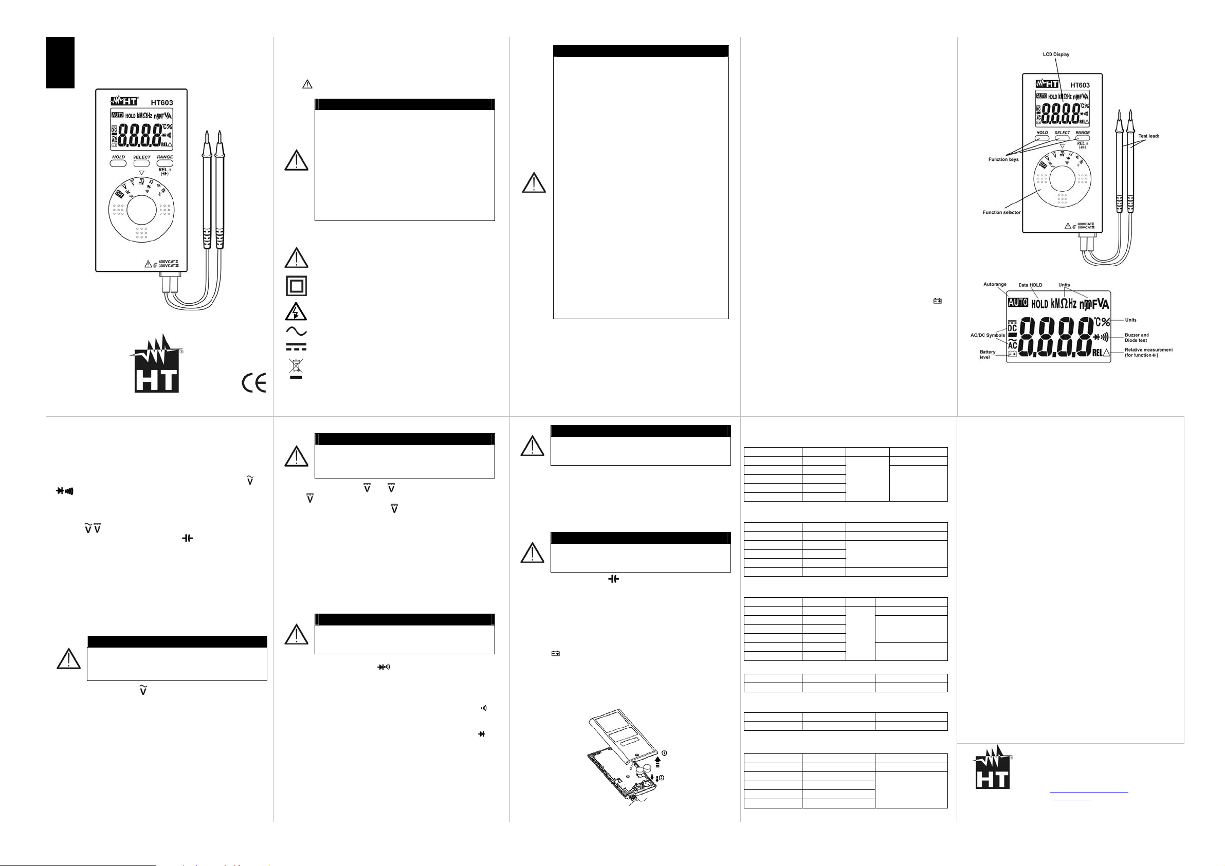
2. GENERAL DESCRIPTION
HT603 performs the following measurements:
• DC and AC voltage
• Resistance and continuity test
• Frequency and Duty Cycle
• Capacitance
• Diode test
All selectable by means of a 7-position function selector. Function
keys HOLD, SELECT and RANGE/REL∆ are also available (see
§ 5.1, § 5.2 and § 5.3). The selected quantity is displayed with
indication of measuring unit and active functions. The instrument
is provided with an Auto Power Off function consisting in an
automatic switching off 30 minutes after last pressure on keys or
rotation of selector. To resume normal operation, switch on the
instrument again
3. PREPARATION FOR USE
3.1 Initial checks
This instrument was checked both mechanically and electrically
prior to shipment. All possible cares and precautions were taken
to let you receive the instrument under perfect conditions.
Notwithstanding we suggest you to check it rapidly (any damage
may have occurred during transport – if so please contact the
local distributor from whom you bought the item). Make sure that
all standard accessories mentioned in § 8 are included. Should
you have to return back the instrument for any reason please
follow the instructions mentioned in § 9
3.2 Supply voltage
The instrument is powered by 2x1.5V button batteries type LR44
included on meter. When batteries are low the symbol "
displayed. To replace/insert batteries follow the instructions
indicated in § 7
3.3 Calibration
The instrument complies with the technical specifications
contained in this manual and such compliance is guaranteed for
12 months
3.4 Storage
After a period of storage under extreme environmental conditions
exceeding the limits mentioned in § 8 let the instrument resume
normal operating conditions before using it
8. TECHNICAL SPECIFICATIONS
The accuracy is referred to 23°C± 5°C, <80%RH
AC Voltage
Meas. Range Resolution Frequency Accuracy
400.0mV 0.1mV
4.000V 0.001V
40.00V 0.01V
400.0V 0.1V
600V 1V
Input impedance: 10MΩ, <100pF; Overload protection: 600V rms
DC Voltage
Meas. Range Resolution Accuracy
400.0mV 0.1mV
4.000V 0.001V
40.00V 0.01V
400.0V 0.1V
600V 1V
Input impedance: 10MΩ, <100pF; Overload protection: 600V rms
Resistance and Continuity test
Meas. Range Resolution Buzzer Accuracy
400.0Ω 0.1Ω
4.000kΩ 0.001kΩ
400.0kΩ 0.1kΩ
4.000MΩ 0.001MΩ
40.00MΩ 0.01MΩ
50 ÷ 500Hz
<50Ω
(range
400Ω)
Frequency
Meas. Range Resolution Accuracy
0.001Hz ÷5MHz
Sensitivity: 1.0Vp-p (square wave) ; Vmax: 5.0Vp-p, 240V (50/60Hz)
Duty Cycle
Meas. Range Resolution Accuracy
0.1% ÷ 99.9% 0.1%
Sensitivity: 1.0Vp-p 30% ≤Duty≤70% (square wave) ; Vmax: 5.0Vp-p
Capacitance
Meas. Range Resolution Accuracy
50.00nF 0.01nF
500.0nF 0.1nF
5.000µF 0.001µF
50.00µF 0.01µF
100.0µF 0.1µF
0.001Hz ÷ 0.001MHz ±(0.3%rdg+5dgt)
±(1.5%rdg+5dgt)
±(0.9%rdg+5dgt)
±(0.7%rdg+5dgt)
±(0.6%rdg+2dgt)
±(0.7%rdg+5dgt)
±(0.9%rdg+5dgt)
±(0.9%rdg+2dgt) 40.00kΩ 0.01kΩ
±(1.5%rdg+5dgt)
±(0.5%rdg+3dgt)
±(5.0%rdg+0.2nF)
±(2.9%rdg+5dgt)
4. INSTRUMENT AND DISPLAY DESCRIPTION
" is
Safety: IEC/EN61010-1
Measurement category: CAT III 300V , CAT II 600V, Pollution degree: 2
Insulation: double insulation
Compliance with 2004/108/CE (EMC) and 2006/95/CE (LVD) Directives
Display: LCD, 4dgt, 5000 points
Sampling rate: 3 times/s
Diode test: test current 1.1mA, open voltage: 1.5VDC (max)
Over range indication: “OL.” or “-OL.” symbols at display
Power supply: 2x1.5V button batteries type LR44
Auto Power OFF: after 30 minutes of idleness
Reference temperature/humidity: 23°C± 5°C (73°F ± 41°F) ; <80%RH
Working temp.: 0 ÷30°C <80%RH ; 30 ÷40°C <75%RH ; 40 ÷50°C <45%RH
Storage temperature/humidity: -20 ÷ 60°C (-4°F ÷ 140°F) ; <80%RH
Max height of use: 2000 m (6562ft)
Dimensions (LxWxH): 112x56x12mm (4x2x0.5in)
Weight (with batteries): 115g (0.2lv)
Included accessories: test leads, batteries (fitted), user manual
9. SERVICE
9.1 Warranty conditions
This instrument is guaranteed for one year against material or
production defects, in accordance with our general sales conditions.
During the warranty period the manufacturer reserves the right to
decide either to repair or replace the product. Should you need for
any reason to return back the instrument for repair or replacement
take prior agreements with the local distributor from whom you
bought it. Do not forget to enclose a report describing the reasons for
returning (detected fault). Use only original packaging. Any damage
occurred in transit due to not original packaging will be charged
anyhow to the customer
9.2 Service
Should the instrument not work properly, make sure that batteries are
correctly installed and working before contacting your distributor, also
check the test leads and replace them if necessary. Should you need
for any reason to return back the instrument for repair or replacement
take prior agreements with the local distributor from whom you
bought it. Do not forget to enclose a report describing the reasons for
returning (detected fault). Use only original packaging. Any damage
occurred in transit due to not original packaging will be charged
anyhow to the customer. The manufacturer will not be responsible for
any damage to persons or things
HT ITALIA SRL
Via della Boaria, 40
48018 – Faenza (RA) – ITALY
Tel: +39-0546-621002
Fax: +39-0546-621144
Web: www.ht-instruments.com
Email: ht@htitalia.it
Page 3

A
•
A
A
ESP
MANUAL DE INSTRUCCIONES
HT603
© Copyright HT ITALIA 2011 Versión ES 1.01 - 19/12/2011
5. DESCRIPCIÓN DE LAS TECLAS FUNCIÓN
5.1 Tecla HOLD
Pulsando la tecla HOLD activamos la congelación del valor leido en
el visualizador. Aparecerá en pantalla el mensaje "HOLD”. Esta
modalidad puede ser desactivada si pulsamos nuevamente la tecla
HOLD
5.2 Tecla SELECT
La presión repetida de la tecla SELECT permite seleccionar las subfunciones correspondientes a las posiciones del selector
y Hz%
Ω
5.3 Tecla RANGE/REL∆
Pulse la tecla RANGE/REL para activar el cambio de rango manual
(funciones
Pulse la tecla RANGE/ REL∆ (sólo función
, y Ω) apagando el texto "AUTO" en el visualizador.
) para activar la
medida relativa. El instrumento muestra el símbolo “REL∆ ” y pone a
cero el valor en el visualizador. Pulse nuevamente la tecla para salir
de la función
5.4 Deshabilitación función Autoapagado
Para deshabilitar la función Autoapagado:
1 Apague el instrumento (OFF)
2 Encienda el instrumento manteniendo pulsada la tecla RANGE
6. INSTRUCCIONES OPERATIVAS
6.1 Medida de Tensión CA, Frecuencia y Ciclo de trabajo
ATENCIÓN
La máxima tensión CA de entrada es 600V. No mida
tensiones que superen los límites indicados en este
manual. Si se superan estos límites de tensión puede
causar el choque eléctrico al usuario y daños al
1. Seleccione la posición Hz%. Los símbolos “AC” y “AUTO” se
2. Posicione la punta roja y la punta negra en el circuito en examen.
3. El mensaje "OL." indica que el valor de la tensión excede el valor
4. Pulse la tecla SELECT para la visualización del valor de
5. Pulse la tecla SELECT para la visualización del valor de ciclo de
6. Para el uso de la función HOLD ver el § 5.1
instrumento
muestran en el visualizador. Pulse la tecla SELECT para
seleccionar la medida de tensión CA (símbolo “V” en el
visualizador) y la tecla RANGE para la selección del campo
manual (ver § 5.3)
El valor de la tensión CA se muestra en el visualizador
máximo medible
frecuencia. El símbolo “Hz” se muestra en el visualizador
trabajo. El símbolo “%” se muestra en el visualizador
Hz%,
1. PRECAUCIONES Y MEDIDAS DE SEGURIDAD
El instrumento ha sido proyectado conforme a la directiva
IEC/EN61010-1, relativa a los instrumentos de medida electrónicos.
Para su seguridad y para evitar dañar el instrumento, le rogamos
que siga los procedimientos descritos en el presente manual y
preste particular atención a todas las notas precedidas por el
símbolo
ATENCIÓN
• No efectúe medidas en entornos húmedos
• No efectúe medidas en presencia de gas o
materiales explosivos, combustibles o en
ambientes con polvo
• Evite el contacto con el circuito en examen si
no se están efectuando medidas
• Evite contactos con partes metálicas
expuestas, con terminales de medidas
inutilizados, circuitos, etc
• No efectúe ninguna medida si encuentra
alguna anomalía en el instrumento como
deformaciones, roturas, pérdidas de
sustancias, ausencia de visualizador, etc
• Preste particular atención cuando se efectúen
medidas de tensión superiores a 20V ya que
En el presente manual y en el instrumento se utilizan los siguientes
símbolos:
existe el riesgo del choque eléctrico
Atención: aténgase a las instrucciones indicadas en
el manual; un uso impropio puede causar daños al
instrumento o a sus componentes.
Instrumento con doble aislamiento
Peligro Alta Tensión: riesgo de shock eléctrico
Tensión CA
Tensión CC
ATENCIÓN: el símbolo adjunto indica que el
instrumento pila y sus accesorios deben ser
reciclados separadamente y tratados de modo
correcto
6.2 Me di da de Tensi ón CC
ATENCIÓN
La máxima tensión CC de entrada es 600V. No mida
tensiones que superen los límites indicados en este
manual. Si se superan estos límites de tensión puede
causar el choque eléctrico al usuario y daños al
instrumento
1. Seleccione las posiciones o m . Los símbolos “DC” y “AUTO”
) aparecen en el visualizador. Pulse la tecla RANGE para
(sólo
activar el cambio de escala manual (sólo
) (ver § 5.3)
2. Posicione la punta roja (polo positivo) y la punta negra (polo
negativo) respectivamente en los puntos en el circuito en
examen. El valor de la tensión CC se muestra en el visualizador
3. El símbolo “-“ en el visualizador indica que la dirección de la
tensión está invertida respecto a la conexión anterior
4. El mensaje "OL." indica que el valor de la tensión es superior al
fondo de escala
5. Para el uso de la función HOLD ver el § 5.1
6.3 Medida de Resistencia, Prueba de Continuidad y Diodos
ATENCIÓN
Antes de realizar cualquier medida en un circuito de
resistencia, desconecte la alimentación del circuito y
asegúrese que los condensadores estén
1. Seleccione la posición Ω . Los símbolos “MΩ” y “AUTO”
2. Inserte las dos puntas de prueba en el punto deseado del
3. Pulse la tecla SELECT para seleccionar la prueba de
4. Pulse la tecla SELECT para seleccionar la prueba de diodos
descargados
aparecen en el visualizador. Pulse la tecla RANGE para activar
el cambio de escala manual (ver § 5.3)
circuito, luego el instrumento muestra el resultado
continuidad (símbolo “
” en el visualizador). El zumbador emite
una señal acústica cuando el valor de la resistencia medida es
inferior a 50Ω
(símbolo “
” en el visualizador). Conecte la punta roja al ánodo
del diodo y la punta negra al cátodo. El instrumento muestra la
tensión de polarización directa. Tal tensión es típicamente entre
0.4 ~ 0.9V para una buena unión. Invierta las conexiones y mida
la caida de potencial en los sentidos del diodo. Un resultado
“OL.” indica el correcto funcionamiento de la unión
1.1 Instrucciones preliminares
TENCIÓN
Este instrumento ha sido proyectado para su
uso en entornos con nivel de polución 2
• Puede ser utilizado para medidas de TENSIÓN
en instalaciones con CAT III 300V y CAT II
600V
• Sólo las puntas de prueba incluidas en el
embalaje del instrumento garantizan las
normas de seguridad. Por lo tanto deben estar
en buenas condiciones e sustituirlas si fuese
necesario con modelos idénticos
• No efectúe medidas en circuitos que superen
los límites de corriente y tensión especificados
• No efectúe medidas en condiciones
ambientales fuera de las limitaciones indicadas
en el § 8
• Controle que las pilas esté instaladas
correctamente
• Antes de conectar las puntas al circuito en
examen, controle que el conmutador esté
posicionado correctamente
• Controle que el visualizador LCD y el
conmutador indiquen la misma función
• Antes de accionar el conmutador, desconecte
las puntas de prueba del circuito en examen
• Cuando el instrumento está conectado al
circuito en examen no toque nunca ningún
terminal inutilizado
• Si, durante una medida, el valor o el signo de
la magnitud en examen permanece constante
1.2 Definición de categoría de sobretensión
controle si está activada la función HOLD
En acuerdo con la norma IEC/EN61010-1 los circuitos están
subdivididos en las siguientes categorías de medida:
• La CAT IV sirve para las medidas efectuadas sobre una fuente
de una instalación de baja tensión
• La CAT III sirve para las medidas efectuadas en instalaciones
interiores de edificios
• La CAT II sirve para las medidas efectuadas sobre circuitos
conectados directamente a las instalaciones de baja tensión
• La CAT I sirve para las medidas efectuadas sobre circuitos no
conectados directamente a la RED DE DISTRIBUCIÓN
6.4 Medida de Frecuencia y Ciclo de trabajo
TENCIÓN
Para evitar el riesgo de sufrir un choque eléctrico no
realice nunca medida en circutos con más de 600V
1. Seleccione la posición Hz%. Pulse la tecla SELECT para
CA/CC
seleccionar la medida de frecuencia o ciclo de trabajo. Los
símbolos “Hz” o “%”se muestra en el visualizador. Inserte las dos
puntas de prueba en el punto deseado del circuito, luego el
instrumento muestra el resultado (en kHz o MHz) o el valor
percentual
6.5 Medida de Capacidad
TENCIÓN
Antes de realizar medidas de capacidad sobre
circuitos o condensadores, quite la alimentación al
circuito bajo examen y deje descargar todas las
1. Seleccione la posición ”. Pulse la tecla RANGE/REL∆ para
2. Posicione las conexiones en los terminales del condensador en
3. El mensaje "OL." indica que el valor de la capacidad es superior
7. SUSTITUCIÓN DE LAS PILAS
Cuando sobre el visualizador LCD aparece el símbolo "
necesario sustituir las pilas como sigue:
1. Apague el instrumento con la tecla OFF
2. Quite el tornillo de fijación de la tapa de pilas
3. Desconecte las pilas y inserte nueva pilas del mismo tipo
4. Vuelva a poner la parte inferior
capacidades presentes en este
hacer “nF” medidas de capacidad. El instrumento muestra el
símbolo “REL∆” y cera el valor en el visualizador
examen respetando la polaridad po sitiv a (punta roj a) y nega tiv a (punta
negra). El valor de la capacidad se muestra en el visualizador
al fondo de escala
2. DESCRIPCIÓN GENERAL
El instrumento HT603 puede efectuar las siguientes medidas:
• Tensión CC y CA
• Resistencia y Prueba Continuidad
• Frecuencia y ciclo de trabajo
• Capacidad
• Prueba de diodos
Cada unos de estos parámetros pueden ser seleccionados
mediante el selector rotativo de 7 posiciones. Existen las teclas
función HOLD, SELECT y RANGE/REL∆ (ver el § 5.1, § 5.2 y §
5.3). El parámetro seleccionado aparece en el visualizador con
indicaciones de la unidad de medida y de las funciones puestas
en marcha. El instrumento posee un dispositivo de autoapagado
que apaga automáticamente el instrumento transcurridos 30
minutos desde la última vez que se presione una tecla o se haga
rotar el selector.
3. PREPARACIÓN PARA EL USO
3.1 Controles iniciales
El instrumento, antes de ser enviado, ha sido controlado desde el
punto de vista eléctrico y mecánico. Han sido tomadas todas las
precauciones posibles con el fin que el instrumento pueda ser
enviado sin ningún daño. Por lo tanto aconsejamos controlar
exhaustivamente el instrumento para encontrar eventuales daños
producidos durante el transporte. Si se encontrase cualquier
anomalía contacte inmediatamente con el transportista. Por otra
parte le aconsejamos que controle que el embalaje contenga
todas las piezas indicadas en el § 8 y en el caso de que exista
cualquier discrepancia contacte con el distribuidor. Si por
cualquier causa fuese necesario sustituir el instrumento, se ruega
seguir las instrucciones indicadas en el § 9
3.2 Alimentación del instrumento
El instrumento se alimenta mediante 2x1.5V botón pilas modelo
LR44 incluidas en el instrumento. Cuando la pila está descargada
aparece el símbolo "
instrucciones reflejadas en el § 7
3.3 Calibrado
". Para sustituir la pila siga las
El instrumento respeta las características técnicas reflejadas en
este manual. Las prestaciones del instrumento están
garantizadas durante un año
3.4 Almacenamiento
Para garantizar medidas precisas, después de un largo período
de almacenamiento en condiciones ambientales extremas,
espere a que el instrumento esté en condiciones normales antes
de realizar cualquier medida (vea el § 8)
8. ESPECIFICACIONE TECNICAS
La incertidumbre es relacionada a 23°C± 5°C, <80%RH
Tensión CA
Campo medida Resolución Frecuencia Incertidumbre
400.0mV 0.1mV
4.000V 0.001V
40.00V 0.01V
400.0V 0.1V
600V 1V
Impedancia de entrada: 10MΩ, <100pF ; Prot. sobrecarga: 600V rms
Tensión CC
Campo medida Resolución Incertidumbre
400.0mV 0.1mV
4.000V 0.001V
40.00V 0.01V
400.0V 0.1V
600V 1V
Impedancia de entrada: 10MΩ, <100pF ; Prot. sobrecarga: 600V rms
Resistencia y Prueba de Continuidad
Campo medida Resolución Buzzer Incertidumbre
400.0Ω 0.1Ω
4.000kΩ 0.001kΩ
40.00kΩ 0.01kΩ
400.0kΩ 0.1kΩ
4.000MΩ 0.001MΩ
40.00MΩ 0.01MΩ
Frecuencia
" es
Campo medida Resolución Incertidumbre
0.001Hz ÷5MHz
Sensitividad: 1.0Vp-p (onda cuadrada) ; Vmax: 5.0Vp-p, 240V (50/60Hz)
Ciclo de Trabajo
Campo medida Resolución Incertidumbre
0.1% ÷ 99.9% 0.1%
Sensitividad: 1.0Vp-p 30% ≤Duty≤70% (onda cuadrada) ; Vmax: 5.0Vp-p
Capacidad
Campo medida Resolución Incertidumbre
50.00nF 0.01nF
500.0nF 0.1nF
5.000µF 0.001µF
50.00µF 0.01µF
100.0µF 0.1µF
0.001Hz ÷ 0.001MHz ±(0.3%lectura+5dgt)
50 ÷ 500Hz
<50Ω
(campo
400Ω)
±(1.5%lec+5dgt)
±(0.9%lec+5dgt)
±(0.7%lectura+5dgt)
±(0.6%lectura+2dgt)
±(0.7%lectura+5dgt)
±(0.9%lectura+5dgt)
±(0.9%lectura+2dgt)
±(1.5%lectura+5dgt)
±(0.5%lectura+3dgt)
±(5.0%lectura+0.2nF)
±(2.9%lectura+5dgt)
4. DESCRIPCIÓN DEL INSTRUMENTO Y VISUALIZADOR
Seguridad: IEC/EN61010-1
Categoria de medida: CAT III 300V , CAT II 600V, Nivel de Polución: 2
Aislamiento: doble aislamiento
Conformidad en las Directivas 2004/108/CE (EMC) y 2006/95/CE (LVD)
Visualizador: 4 LCD, 5000 puntos
Frecuencia de muestreo: 3 voltas/s
Prueba de diodos: corriente de prueba 1.1mA, tensión en vacio: 1.5VDC (max)
Indicación fuera escala: “OL.” o bien “-OL.” en el visualizador
Alimentación: 2x1.5V botón pilas tipo LR44, GPA76P
AutoApagado: después 30 minutos de no utilizar
Temperatura/Humedad de referencia: 23°C± 5°C (73°F ± 41°F) ; <80%RH
Temp. de uso: 0 ÷30°C <80%RH ; 30 ÷40°C <75%RH ; 40 ÷50°C <45%RH
Temperatura/Humedad de almacenaje: --20 ÷ 60°C (-4°F ÷ 140°F) ; <80%RH
Altitud max de uso: 2000m (6562ft)
Dimensiones (LxLaxH): 112x56x12mm (4x2x0.5in)
Peso (incluidas las pilas): 115g (0.2lv)
Accesorios en dotación: puntas de prueba, pilas, manual de instrucciones
9. ASISTENCIA
9.1 Condiciones de garantía
Este equipo está garantizado en cualquier material en su defecto de
fábrica, de acuerdo con las condiciones generales de venta. Durante
el período de garantía (un año), las piezas defectuosas serán
reemplazadas, el fabricante se reserva el derecho de decidir si
repara o canjea el producto. En el caso de tener que devolver el
instrumento al departamento post-venta o al distribuidor regional, el
envío del instrumento va a cargo del cliente. La entrega debe estar
acordada con el consignatario. Para el envío añada una nota en el
mismo paquete, lo más claro posible, las razones de reenvío y
usando el embalaje original.
9.2 Servicio
Si el equipo no funciona correctamente, antes de contactar con el
servicio técnico compruebe el estado de la pila, las puntas de
prueba, etc., y cámbielo si fuese necesario. Si el equipo no funciona
correctamente consulte el modo de funcionamiento descrito en este
manual. Cuando el instrumento deba enviarse al servicio postventa
o a un distribuidor, el transporte será a cargo del cliente. La
expedición deberá, en cada caso y previamente acordado y
aceptado el presupuesto por escrito. El envío, siempre debe
acompañarse de una nota explicativa lo más detallada posible de los
motivos del envío del instrumento. Utilice sólo el embalaje original,
todo daño causado por el uso de embalajes distintos al original será
a cargo del cliente. El constructor declina toda responsabilidad por
daños causados a personas u objetos.
HT Instruments, S.L.
Legalitat, 89
08024 – Barcelona – SPAIN
Tel: +34-93 408 17 77
Fax: +34-93 408 36 30
Web: www.htinstruments.com
Email: info@htinstruments.com
Page 4

A
•
A
A
DEU
BEDIENUNGSANLEITUNG
HT603
© Copyright HT ITALIA 2011 Ausführung DE 1.01 - 19/12/2011
5. FUNKTIONTASTEN
5.1 HOLD-Taste
Wenn die HOLD Taste gedrückt wird, erscheint ein kleines „H“ und
“HOLD” im Display und die Anzeige wird eingefroren. Um den Data
Hold Modus zu verlassen drücken Sie erneut die HOLD Taste.
5.2 SELECT-Taste
Drücken Sie die SELECT-Taste, um die Unter-Funktionen in Bezug
auf die
Hz%, Ω und Hz%- Schalter-Position zu wählen
5.3 RANGE/REL∆-Taste
Durch Drücken RANGE/REL∆-Taste wird der manuelle Modus
aktiviert (Funktionen
verschwindet. Drücken Sie RANGE/REL∆-Taste (nur Funktion
um die Relativ-Messung zu ermöglichen. Das "REL∆"-Symbol wird
angezeigt und der Wert wird im Display auf Null gesetzt. Drücken Sie
erneut die Taste, um die Funktion zu verlassen
5.4 Auto Power OFF deaktivieren
Um die Auto-Power-OFF-Funktion zu deaktivieren:
1 Schalten Sie das Messgerät aus
2 Schalten Sie das Messgerät an und halten Sie dabei die Taste
RANGE gedrückt
6. MESSUNGEN
6.1 AC-Spannungs, Frequenz und Duty Cycle Messung
Die max. Eingangsspannung ist AC 600V. Versuchen
Sie keine Spannung zu messen, die höher ist. Es
besteht die Gefahr eines Stromschlages und das
Multimeter könnte zerstört werden
1. Drehen Sie den Wahlschalter auf die Hz% Position. Die "AC"
und "AUTO" Symbole werden im Display angezeigt. Drücken Sie
die SELECT-Taste für die Auswahl AC Spannungsmessung
(Symbol "V" im Display) und drücken Sie die Taste RANGE für
die Auswahl der manuellen Bereichswahl (siehe § 5.3)
2. Schließen Sie die rote und schwarze Messleitung an den zu
prüfenden Schaltkreis. Der AC-Spannungswert wird angezeigt
3. Wenn die Meldung "OL." angezeigt wird, ist der maximale
Spannungsbereich überschritten
4. Drücken Sie die SELECT-Taste für die Anzeige des
Frequenzwertes. Das Symbol "Hz" wird im Display angezeigt
5. Drücken Sie die SELECT-Taste für die Visualisierung vom Duty
Cycle Wert (Tastverhältnis). Das Symbol "%" wird im Display
angezeigt
6. Informationen über die HOLD-Funktionen erhalten Sie bei § 5.1
, und Ω) und das "AUTO"-Symbol
ACHTUNG
1. SICHERHEITSHINWEISE
Dieses Multimeter entspricht dem Sicherheitsstandard
IEC/EN61010-1 für elektronische Messgeräte. Zu Ihrer eigenen
Sicherheit und um Schäden des Gerätes zu vermeiden, folgen sie
bitte den Hinweisen in dieser Bedienungsanleitung und lesen sie alle
Hinweise sorgfältig mit diesem Zeichen
.
ACHTUNG
• Vermeiden Sie Messungen in feuchter oder
nasser Umgebung, stellen Sie sicher, dass die
Umgebungsbedingungen innerhalb der
Gerätespezifikation liegen
• Vermeiden Sie Messungen in der Nähe von
explosiven oder brennbaren Gasen oder dort
wo Gase gelagert werden, vermeiden Sie auch
Messungen in der Nähe von extremer Hitze
und Staub
• Achten Sie darauf, dass Sie isoliert zum zu
testenden Objekt stehen
• Berühren Sie keine frei liegenden Metallteile
wie Enden von Prüfleitungen, Steckdosen,
Befestigungen, Schaltkreise etc
• Nehmen Sie keine Messungen vor, wenn Sie
anomale Bedingungen wie Bruchschäden,
Deformationen, Sprünge, Austritt von
Batterieflüssigkeit, keine Anzeige am Display
etc. bemerken
• Sind Sie besonders vorsichtig, wenn Sie
Spannungen über 20V messen, um sich nicht
Folgende Symbole kommen zur Anwendung:
des Risikos von Stromschlägen auszusetzen
VORSICHT: Beziehen Sie sich auf die nicht isoliert
Bedienungsanleitung. Falscher Gebrauch
beschädigt vielleicht das Messgerät oder seine
Bestandteile
Messgerät doppelt isoliert
VORSICHT – gefährliche Spannung. Gefahr eines
Stromschlages.
AC Spannung
DC Spannung
ACHTUNG: Dieses Symbol zeigt an, dass das
Gerät, Batterie und die einzelnen Zubehörteile
fachgemäß und getrennt voneinander entsorgt
6.2. DC-Spannungsmessung
werden müssen
ACHTUNG
Die max. Eingangsspannung ist DC 600V. Versuchen
Sie keine Spannung zu messen, die höher ist. Es
besteht die Gefahr eines Stromschlages und das
Multimeter könnte zerstört werden
1. Drehen Sie den Wahlschalter auf die oder m Position. The
“DC” und “AUTO” (nur
) Symbole werden im Display angezeigt.
Taste RANGE für die Auswahl der manuellen Bereichswahl (nur
) (siehe § 5.3)
2. Verbinden Sie nun die rote und die schwarze Messleitung mit
)
dem positiven und dem negativen-Pol. Der DC-Spannungswert
wird angezeigt
3. Das Symbol "-" im Display zeigt, an das die Prüfleitungen
umgepolt werden müssen, damit die Spannung positiv angezeigt
wird
4. Wenn die Meldung "OL." angezeigt wird, ist der maximale
Spannungsbereich überschritten
5. Informationen über die HOLD-Funktionen erhalten Sie bei § 5.1
6.3 Widerstandsmessung, Durchgangsprüfung und Diodentest
ACHTUNG
Bevor Sie irgendwelche Widerstandsprüfungen
durchführen, entfernen Sie die Spannung am
Messkreis, der geprüft werden soll, und entladen Sie
1. Stellen Sie den Drehschalter in die Position Ω . Das “MΩ” und
2. Schliessen Sie die Messleitungen an das zu prüfende Objekt an.
3. Drücken Sie die SELECT-Taste für die Anzeige des
4. Drücken Sie die SELECT-Taste für die Anzeige des Diodentest
alle Kondensatoren
“AUTO” Symbol wird angezeigt. Drücke die RANGE Taste für die
manuelle Bereichsauswahl (siehe § 5.3)
Der Widerstandswert wird angezeigt
Durchgangsprüfung. Das Symbol “
” wird im Display angezeigt.
Die Durchgangsprüfung ist immer aktiv und der Summer ertönt
bei Messwerten < 50Ω
(Symbol“
” wird im Display angezeigt). Schließen Sie die rote
Messleitung an die positive Seite (Anode) der Diode an und die
schwarze Messleitung an die negative Seite (Kathode).Der
typische Spannungsabfall ist 0.4 ~ 0.9 V, und der Signaltongeber
erklinkt. Kehren Sie die Verbindungen um und messen Sie die
Spannung über der Diode noch einmal. Der Diodentest kann zu
folgenden Anzeigen führen "OL."
1.1 Vorbereitung
CHTUNG
Dieses Gerät wurde für den Gebrauch in
Umgebungen der Schutzklasse 2 entworfen
• Es kann zum Messen von Spannungen in
Installationen der Kategorie CAT III 300V und
der Kategorie CAT II 600V benutzt werden
• Nur die original Messleitungen die beim Gerät
dabei waren, entsprechen den gültigen
Sicherheitsstandards. Sie müssen in gutem
Zustand sein, und, falls nötig, durch identische
ersetzt werden
• Testen Sie keinen, und schließen Sie das
Gerät auch an keinen Stromkreis an, der den
angegebenen Überlastungsschutz übersteigt
• Nehmen Sie keinen Messungen vor, die die
angezeigten Grenzen in § 8 überschreiten
• Überprüfen Sie den korrekten Einsatz der
Batterien
• Vor dem Anschluss der Messleitungen in der
Installation überprüfen Sie, ob der richtige
Messbereich eingestellt ist
• Überprüfen Sie ob das Display und der
Bereichswahlschalter die Selbe Funktion
anzeigen
• Wenn Sie den zu messenden Bereich
ändernder, trennen Sie die Messleitungen
zuerst vom zu prüfenden Objekt, um jeden
Unfall zu vermeiden
• Wenn das Gerät an die Messschaltungen
angeschlossen ist, berühren Sie nie eine
freiliegende Prüfleitung
• Wenn Sie während der Messung einer Größe
oder eines Wertes, die Hold-Funktion drücken
bleibt die Anzeige erhalten, solange die HoldFunktion an ist
1.2 Uberspannungskategorien-definitionen
Die Norm IEC/EN61010-1 Messkategorien sind wie folgt eingeteilt:
• CAT IV ist für Messgeräte, die an der Einspeisung der
Niederspannungsanlagen messen können
• CAT III ist für Messgeräte, die in Gebäudeinstallationen messen
können
• CAT II ist für Messgeräte, die Messungen an Geräten ausführen
die ein Netzanschlusskabel haben
• CAT I ist für Messgeräte, die Messungen an Stromkreisen
ausführen, die nicht direkt mit dem Netz verbunden sind
6.4 Frequenz und Duty Cycle (Tastverhältnis) Messung
CHTUNG
Führen Sie keine Messungen an Schaltungen mit
einer Spannung von mehr als 600V AC / DC, um
mögliche Gefahr eines elektrischen Schlags zu
1. Drehen Sie den Wahlschalter auf die Hz% Position. Drücken Sie
vermeiden
die SELECT-Taste für die Visualisierung vom Frequenzwertes
oder Duty Cycle Wert (Tastverhältnis). Das Symbol “Hz” oder "%"
wird im Display angezeigt. Verbinden Sie die Messleitungen mit
dem Messobjekt. Die Größe der Frequenz (kHz oder MHz) oder
Prozentsatz wird im Display angezeigt
6.4 Kapazitätsmessung
CHTUNG
Bevor Sie irgendwelche Kapazitätsmessung
durchführen, entfernen Sie die Spannung am
Messkreis, der geprüft werden soll und entladen Sie
1. Stellen Sie den Drehschalter in die Position “ ”. Drücken
2. Verbinden Sie die Messleitungen mit dem Kondensator, (achten
3. Wenn die Meldung "OL." angezeigt wird, ist der maximale
7. BATTERIEWECHSEL
Sind die Batterien leer, erscheint dieses Symbol "
Wechseln Sie dann die Batterien:
1. Schalten Sie das Messgerät AUS
2. Entfernen Sie die Schraube und die Batterieabdeckung
3. Entfernen Sie die Batterien und ersetzen Sie diese durch neue
4. Befestigen Sie wieder die Batterieabdeckung
alle Kondensatoren
RANGE/REL∆-Taste für "nF" Kapazitätsmessung. Der Wert
“REL∆” wird im Display auf Null
Sie auf die korrekte Polarität), der Kapazitätswert wird durch die
automatische Bereichswahl erkannt und angezeigt
Kapazitätsmessung überschritten
" im Display.
gleichen Typs
2. ALLGEMEINE BESCHREIBUNG
Das Multimeter HT603 kann folgende Messungen ausführen:
• DC und AC Spannung
• Widerstandmessung und Durchgangsprüfung
• Frequenz und Duty Cycle Messung
• Kapazitätsmessung
• Diodentest
Jede dieser Funktionen kann mittels des 7-stelligen
Drehschalters gewählt werden. Es stehen noch weitere HOLD,
SELECT und RANGE/REL∆ Funktionstasten (§ 5.1, § 5.2 und §
5.3), die eine Umschaltung der Funktionen über das Display
ermöglichen zur Verfügung. Die gewählte Einstellung wird mit
Hinweis auf die Maßeinheit und aktive Funktionen angezeigt. Um
Batteriekapazität zu sparen, wird das Instrument 30 Minuten nach
der letzten Benutzung einer Funktionstaste oder der Veränderung
der Drehschalterposition ausgeschaltet. Die Wiedereinschaltung
erfolgt durch die Wahl der Drehschalterposition OFF und
Wiedereinschalten
3. VORBEREITUNGEN FÜR DEN GEBRAUCH
3.1 Vorabprüfung
Dieses Multimeter wurde vor dem Versand mechanisch und
elektrisch überprüft. Es wurden alle möglichen Maßnahmen
getroffen, damit Sie das Gerät in perfektem Zustand erhalten.
Nichtsdestotrotz empfehlen wir eine schnelle Überprüfung (beim
Transport könnte es eventuell zu Beschädigungen gekommen
sein). – In diesem Fall wenden Sie sich bitte an den Händler, bei
dem Sie das Gerät erworben haben. Gehen Sie sicher, dass alle
in § 8. angeführten Standardzubehörteile vorhanden sind. Sollten
Sie das Gerät aus irgendeinem Grund zurückgeben müssen,
folgen Sie bitte den Anweisungen in § 9
3.2 Stromversorgung
Die Stromversorgung des Gerätes erfolgt durch eine 2x1.5V
Batterien LR44 im Lieferumfang enthalten. Ist die Batterie leer,
erscheint dieses "
Batterie wie im § 7 beschrieben
3.3 Kalibrierung
" Symbol im Display. Wechseln Sie die
Das Gerät entspricht den technischen Spezifikationen, die in
dieser Gebrauchsanweisung angegeben sind, und diese
Entsprechung wird für ein Jahr ab Gebrauch garantiert. Eine
jährliche Neukalibrierung wird empfohlen
3.4 Lagerung
Nach einer Lagerung des Gerätes unter extremen
Umweltbedingungen, die den Zeitraum, der in § 8 angeführt ist,
überschreitet, warten Sie, bis das Gerät wieder normale
Messbedingungen erreicht hat, bevor Sie es benutzen
8. TECHNISCHE FUNKTIONEN
Die Genauigkeit ist bezogen auf 23°C± 5°C, <80%RH
AC Spannung
Messbereich Auflösung Frequenz Genauigkeit
400.0mV 0.1mV
4.000V 0.001V
40.00V 0.01V
400.0V 0.1V
600V 1V
Innenwiderstand: 10MΩ, <100pF ; Schutz vor Überlast: 600Vrms
DC Spannung
Messbereich Auflösung Genauigkeit
400.0mV 0.1mV
4.000V 0.001V
40.00V 0.01V
400.0V 0.1V
600V 1V
Innenwiderstand: 10MΩ, <100pF ; Schutz vor Überlast: 600Vrms
Widerstandsmessung und Durchgangsprüfung
Messbereich Auflösung Buzzer Genauigkeit
400.0Ω 0.1Ω
4.000kΩ 0.001kΩ
400.0kΩ 0.1kΩ
4.000MΩ 0.001MΩ
40.00MΩ 0.01MΩ
50 ÷ 500Hz
<50Ω
(Mess.
400Ω)
Frequenz
Messbereich Auflösung Genauigkeit
0.001Hz ÷5MHz
Sensitivität: 1.0Vp-p (Rechtecksignal) ; Vmax: 5.0Vp-p, 240V (50/60Hz
Tastverhältnis
Messbereich Auflösung Genauigkeit
0.1% ÷ 99.9% 0.1%
Sensitivität: 1.0Vp-p 30% ≤Duty≤70% (Rechtecksignal) ; Vmax: 5.0Vp-p
Kapazitäts-Messbereich
Messbereich Auflösung Genauigkeit
50.00nF 0.01nF
500.0nF 0.1nF
5.000µF 0.001µF
50.00µF 0.01µF
100.0µF 0.1µF
0.001Hz ÷ 0.001MHz ±(0.3%Anz+5dgt)
±(1.5%Anz+5dgt)
±(0.9%Anz+5dgt)
±(0.7%Anz+5dgt)
±(0.6%Anz+2dgt)
±(0.7%Anz+5dgt)
±(0.9%Anz+5dgt)
±(0.9%Anz+2dgt) 40.00kΩ 0.01kΩ
±(1.5%Anz+5dgt)
±(0.5%Anz+3dgt)
±(5.0%Anz+0.2nF)
±(2.9%Anz+5dgt)
4. INSTRUMENT UND ANZEIGE BESCHREIBUNG
Sicherheitsnorm: IEC/EN61010-1
Überspannungskategorie: CAT III 300V , CAT II 600V, Verschmutzungs-grad: 2,
Isolierung: doppelte Isolation
EMV Übereinstimmung mit 2004/108/CE (EMC) und 2006/95/CE (LVD)
Display: LCD, 4 dgt, 5000 Digits
Messrate: 3 times/s
Diodentest: test strom 1.1mA, test spannung 1.5V DC max
Überlastanzeige: “OL.” oder “-OL.”
Batterietyp: 2x1.5V Alkaline Batterien LR44 GPA76P
Auto Power OFF: nach 30 min
Referenzbedingung: 23°C± 5°C (73°F ± 41°F) ; <80%RH
Arbeitstemperatur: 0 ÷30°C <80%RH ; 30 ÷40°C <75%RH ; 40 ÷50°C <45%RH
Lagertemperatur /Lagerfeuchtigkeit: -20 ÷ 60°C (-4°F ÷ 140°F) ; <80%RH
Für Innenbenutzung, max. Höhe: 2000m (6562ft)
Größe (LxWxH): 112x56x12mm (4x2x0.5in)
Gewicht (incl. Batterie): 115g (0.2lv)
Standard Zubehör: Batterien, Bedienerhandbuch
9. SERVICE
9.1 Garantiebedingungen
Für dieses Gerät gewähren wir Garantie auf Material- oder
Produktionsfehler, entsprechend unseren allgemeinen
Geschäftsbedingungen. Während der Garantiefrist behält sich der
Hersteller das Recht vor, das Produkt wahlweise zu reparieren oder
zu ersetzen. Falls Sie das Gerät aus irgendeinem Grund für
Reparatur oder Austausch einschicken müssen, setzen Sie sich bitte
zuerst mit dem lokalen Händler in Verbindung, bei dem Sie das
Gerät gekauft haben. Vergessen Sie nicht, einen Bericht über die
Gründe für das Einschicken beizulegen (erkannte Mängel).
Verwenden Sie nur die Originalverpackung
9.2 Kundendienste
Für den Fall, dass das Gerät nicht korrekt funktioniert, stellen Sie vor
der Kontaktaufnahme mit Ihrem Händler sicher, dass die Batterien
korrekt eingesetzt sind und funktionieren. Überprüfen Sie die
Messkabel und ersetzen Sie diese bei Bedarf. Stellen Sie sicher,
dass Ihre Betriebsabläufe der in dieser Betriebsanleitung
beschriebenen Vorgehensweise entsprechen. Falls Sie das Gerät
aus irgendeinem Grund zur Reparatur oder zum Austausch
einschicken müssen, setzen Sie sich zuerst mit Ihrem lokalen
Händler in Verbindung, beim dem Sie das Gerät gekauft haben.
Vergessen Sie nicht, einen Bericht über die Gründe für das
Einschicken beizulegen (erkannte Mängel). Verwenden Sie nur die
Originalverpackung. Alle Schäden beim Versand, die auf
Nichtverwendung der Originalverpackung zurückzuführen sind, hat
auf jeden Fall der Kunde zu tragen. Der Hersteller übernimmt keine
Haftung für Personen- oder Sachschäden.
HT INSTRUMENTS
Am Waldfriedhof 1b, 41352 Korschenbroich
Tel: +49-2161 564 581, Fax: 02161 564 583
Web: www.ht-instruments.de;
Email: ht@ht-instruments.de
Page 5

A
A
•
A
A
A
A
FRA
MANUEL D'UTILISATION
HT603
© Copyright HT ITALIA 2011 Version FR 1.01 - 19/12/2011
5. DESCRIPTION DES TOUCHES DE FONCTION
5.1 Touche HOLD (Verr)
La pression de la touche HOLD active le verrouillage de la valeur de
la grandeur affichée à l'écran. Après avoir appuyé sur cette touche,
le message « HOLD » s'affiche à l'écran. Appuyer à nouveau sur la
touche HOLD pour quitter cette fonction.
5.2 Touche SELECT
La pression en séquence de la touche SELECT permet de
sélectionner les sous-fonctions correspondant aux positions du
sélecteur
5.3 Touche RANGE / REL∆
Appuyer sur la touche RANGE/REL∆ pour activer le changement
d'échelle manuelle sur l'instrument (fonctions
le message « AUTO » à l'écran. Appuyer sur la touche RANGE/
REL∆ (fonction
correspondante. L'instrument montre le symbole « REL ∆ » et met à
zéro la valeur à l'écran. Appuyer à nouveau sur la touche pour quitter
cette fonction.
5.4 Invalidation Auto Power OFF (Arrêt Auto)
Pour invalider la fonction Auto Power OFF :
1. Eteindre l'instrument (OFF)
2. Allumer l'instrument en gardant enfoncée la touche RANGE.
6. EXECUTION DES MESURES
6.1 Mesures de Tension AC, Fréquence et Duty Cycle
1. Sélectionner la position Hz%. Les symboles « AC » et
2. Positionner l’embout rouge et l'embout noir sur le circuit sous
3. Le message « OL. » indique que la valeur de tension dépasse la
4. Appuyer sur la touche SELECT pour afficher la valeur de
5. Appuyer sur la touche SELECT pour afficher la valeur de Duty
6. Pour utiliser la fonction Data HOLD, consulter la § 5.1.
Hz%, Ω et Hz%.
, et Ω) en éteignant
seulement) pour activer la mesure
ATTENTION
La tension d’entrée maximale AC est de 600V. Ne
pas mesurer de tensions excédant les limites
indiquées dans ce manuel. Le dépassement de ces
limites pourrait entraîner des chocs électriques pour
l'utilisateur et endommager l’instrument.
« AUTO » sont présents à l'écran. Appuyer sur la touche
SELECT pour sélectionner la mesure de tension AC (symbole
« V » à l'écran) et sur la touche RANGE pour sélectionner
l'échelle manuelle (voir la § 5.3)
test. La valeur de tension AC apparaît à l’écran.
valeur maximale mesurable.
fréquence. Le symbole « Hz » s'affiche à l'écran.
Cycle (cycle de travail). Le symbole « % » s'affiche à l'écran.
1. PRECAUTIONS ET MESURES DE SECURITE
Cet instrument a été conçu conformément à la directive
CEI/EN61010-1, relative aux instruments de mesure électroniques.
Pour votre propre sécurité et afin d’éviter tout endommagement de
l’instrument, veuillez suivre avec précaution les instructions décrites
dans ce manuel et lire attentivement toutes les remarques
précédées du symbole
.
TTENTION
• Ne pas effectuer de mesures dans des endroits
humides.
• Eviter d’utiliser l’instrument en la présence de
gaz ou matériaux explosifs, de combustibles ou
dans des endroits poussiéreux.
• Se tenir éloigné de l’instrument sous test si
aucune mesure n’est en cours d’exécution.
• Ne pas toucher de parties métalliques
exposées telles que des bornes de mesure
inutilisées, des circuits, etc.
• Ne pas effectuer de mesures si vous détectez
des anomalies sur l’instrument telles qu’une
déformation, une cassure, des fuites de
substances, une absence d’affichage de
l’écran, etc.
• Prêter une attention particulière lorsque vous
mesurez des tensions au-delà de 20V afin
Dans ce manuel, et sur l’instrument, on utilisera les symboles
suivants :
6.2 Mesure de tension DC
d’éviter le risque de chocs électriques.
Attention : s’en tenir aux instructions reportées dans
ce manuel ; une utilisation inappropriée pourrait
endommager l’instrument ou ses composants.
Instrument à double isolement.
Danger haute tension : risque de chocs électriques.
Tension AC
Tension DC
ATTENTION : ce symbole indique que l’instrument,
ses accessoires et les piles doivent être soumis à un
tri sélectif et éliminés convenablement.
TTENTION
La tension d’entrée maximale DC est de 600V. Ne
pas mesurer de tensions excédant les limites
indiquées dans ce manuel. Le dépassement de ces
limites pourrait entraîner des chocs électriques pour
l'utilisateur et endommager l’instrument.
1. Sélectionner les positions ou m du sélecteur. Les symboles
« DC » et « AUTO » (seulement
) sont présents à l'écran.
Appuyer sur la touche RANGE pour la sélection de l'échelle de
mesure manuelle (seulement
) (voir la § 5.3)
2. Positionner l’embout rouge (polarité positive) et l'embout noir
(polarité négative) sur le circuit sous test. La valeur de tension
DC apparaît à l’écran.
3. L'affichage du symbole « - » sur l'écran de l'instrument indique
que la tension a une direction opposée par rapport à la
connexion effectuée.
4. Le message « OL. » indique que la valeur de tension dépasse la
valeur maximale mesurable.
5. Pour utiliser la fonction Data HOLD, consulter la § 5.1.
6.3 Mesure de résistance, test de continuité et test des diodes
TTENTION
Avant d'effectuer toute mesure de résistance, vérifier
que l’alimentation du circuit sous test est coupée et
que tous les condensateurs, si présents, sont
1. Sélectionner la position Ω . Les symboles « MΩ » « O.L » et
2. Positionner les embouts sur les points désirés du circuit sous
3. Appuyer sur la touche SELECT pour sélectionner le test de
4. Appuyer sur la touche SELECT pour sélectionner le test des
déchargés.
« AUTO » sont présents à l'écran. Appuyer sur la touche RANGE
pour la sélection de l'échelle de mesure manuelle (voir la § 5.3).
test. La valeur de résistance apparaît à l’écran.
continuité (symbole «
» à l'écran). L'alarme sonnera pour les
valeurs de résistance <50Ω.
diodes (symbole «
» à l'écran). Relier l'embout de mesure
rouge à l'anode de la diode et l'embout noir à la cathode. La
tension de polarisation directe, typiquement 0.4 ~ 0.9V, est
affichée à l'écran. Inverser les connexions sur la diode. Si
« OL. » est affiché à l'écran, la jonction fonctionne correctement.
1.1 Instructions préliminaires
TTENTION
Cet instrument a été conçu pour une utilisation
dans un environnement avec niveau de
pollution 2.
• Il peut être utilisé pour des mesures de
TENSION sur des installations en CAT III 300V
et CAT II 600V.
• Seuls les embouts fournis avec l’instrument
garantissent la conformité avec les normes de
sécurité. Ils doivent être en bon état et, si
nécessaire, remplacés à l’identique.
• Ne pas mesurer de circuits dépassant les
limites de tension spécifiées.
• Ne pas effectuer de mesures dans des
conditions environnementales en dehors des
limites indiquées à la § 8.
• Vérifier si les piles sont insérées correctement.
• Avant de connecter les embouts au circuit à
tester, vérifier que le sélecteur est positionné
correctement.
• Contrôler que l’afficheur LCD et le sélecteur
indiquent la même fonction.
• Avant d’activer le sélecteur, déconnecter les
embouts de mesure du circuit sous test.
• Lorsque l’instrument est connecté au circuit
sous test, ne jamais toucher les bornes
inutilisées.
• Si une valeur mesurée ou le signe d’une
grandeur sous test restent constants pendant
la mesure, contrôler si la fonction HOLD (Verr)
1.2 Définition de catégorie de surtension
est activée.
Conformément à la norme CEI/EN61010-1, les circuits sont
divisés dans les catégories de mesure qui suivent :
• La CAT IV sert pour les mesures exécutées sur une source
d'installation à faible tension.
• La CAT III sert pour les mesures exécutées sur des installations
dans les bâtiments.
• La CAT II sert pour les mesures exécutées sur les circuits
connectés directement à l'installation à faible tension.
• La CAT I sert pour les mesures exécutées sur les circuits n'étant
pas connectés directement au RESEAU DE DISTRIBUTION.
6.4 Mesure de fréquence et Duty Cycle
TTENTION
Ne pas effectuer de mesures sur des circuits avec
tension supérieure à 600V AC/DC afin d'éviter tout
1. Sélectionner la position Hz%. Appuyer sur la touche SELECT
choc électrique et dommage à l'instrument.
pour sélectionner la mesure de fréquence ou Duty Cycle. Les
symboles « Hz » et « % » sont présents à l'écran. Positionner les
embouts sur les points désirés du circuit sous test. La valeur de
fréquence (en kHz ou MHz) ou bien la valeur en pourcentage sont
affichées.
6.5 Mesure de Capacité
TTENTION
Avant d'effectuer de mesures de capacité sur circuits
ou condensateurs, couper l'alimentation au circuit
sous test et laisser décharger toutes les capacités s'y
1. Sélectionner la position « ». Appuyer sur la touche
2. Positionner les embouts aux extrémités du condensateur sous test en
3. Le message « OL. » indique que la valeur de capacité dépasse la
7. REMPLACEMENT DES PILES
Lorsque le symbole «
comme il suit :
1. Eteindre l'instrument par la touche OFF
2. Dévisser la vis de fixation du logement des piles et le retirer.
3. Retirer les piles et les remplacer par d'autres du même type.
4. Remettre en place le couvercle du logement des piles.
trouvant.
RANGE/REL∆ en cas de mesure de capacité en « nF ». La valeur
affichée se met à zéro.
respectant, le cas échéant, les polarités positives (câble rouge) et
négatives (câble noir) sur le condensateur sous test. La valeur de
capacité apparaît à l’écra n.
valeur maximale mesurable.
» s'affiche, il faut remplacer les piles
.
2. DESCRIPTION GENERALE
L'instrument HT603 exécute les mesures suivantes :
• Tension DC et AC
• Résistance et Test de continuité
• Fréquence et Duty Cycle (cycle de travail)
• Capacité
• Test des diodes
Chacune de ces fonctions peut être sélectionnée à l’aide d’un
sélecteur à 7 positions. Les touches de fonction HOLD, SELECT
et RANGE/REL∆ sont également présentes (voir § 5.1, § 5.2 et §
5.3). La grandeur sélectionnée s'affiche à l'écran LCD avec
l'indication de l'unité de mesure et des fonctions validées.
L'instrument est également équipé d'un dispositif d'Auto Power
OFF (Arrêt Auto) qui éteint automatiquement l'instrument après
30 minutes de la dernière pression des touches de fonction ou
rotation du sélecteur.
3. PREPARATION A L'UTILISATION
3.1 Vérification initiale
L’instrument a fait l’objet d’un contrôle mécanique et électrique
avant d’être expédié. Toutes les précautions ont été prises pour
garantir une livraison de l’instrument en bon état. Toutefois, il est
recommandé d’effectuer un contrôle rapide afin de détecter des
dommages qui auraient pu avoir lieu pendant le transport. En cas
d’anomalies, n’hésitez pas à contacter votre commissionnaire de
transport. S’assurer que l’emballage contient tous les accessoires
listés à la § 8. Dans le cas contraire, contacter le revendeur. S’il
était nécessaire de renvoyer l’instrument, veuillez respecter les
instructions dont à la § 9.
3.2 Alimentation de l’instrument
L'instrument est alimenté par 2 piles de 1.5V de type LR44
insérées à son intérieur. Lorsque les piles sont déchargées, le
symbole «
instructions de la § 7.
3.3 Etalonnage
» s'affiche. Remplacer les piles en suivant les
L’instrument est conforme aux spécifications techniques décrites
dans ce manuel. Ses performances sont garanties pendant un
an.
3.4 Conservation
Afin d’assurer la précision des mesures, après une longue
période de stockage en conditions environnementales extrêmes,
il est conseillé d’attendre le temps nécessaire afin que
l’instrument revienne aux conditions normales (voir Conditions
environnementales à la § 8).
8. SPECIFICATIONS TECHNIQUES
Imprécision référée à 23°C± 5°C, <80%HR
Tension AC
Echelle de mesure Résolution Fréquence Imprécision
400.0mV 0.1mV
4.000V 0.001V
40.00V 0.01V
400.0V 0.1V
600V 1V
Impédance d'entrée : 10MΩ, <100pF ; Prot. contre surtension : 600V rms
Tension DC
Echelle de mesure Résolution Imprécision
400.0mV 0.1mV
4.000V 0.001V
40.00V 0.01V
400.0V 0.1V
600V 1V
Impédance d'entrée : 10MΩ, <100pF ; Prot. contre surtension : 600V rms
Résistance et Test de continuité
Echelle de mesure Résolution Alarme Imprécision
400.0Ω 0.1Ω
4.000kΩ 0.001kΩ
40.00kΩ 0.01kΩ
400.0kΩ 0.1kΩ
4.000MΩ 0.001MΩ
40.00MΩ 0.01MΩ
50 ÷ 500Hz
(Echelle
400Ω)
Fréquence
Echelle de mesure Résolution Imprécision
0.001Hz ÷5MHz
Sensibilité : 1.0Vp-p (Onde carrée) ; Vmax : 5.0Vp-p, 240V (50/60Hz)
Duty Cycle
Echelle de mesure Résolution Imprécision
0.1% ÷ 99.9% 0.1%
Sensibilité : 1.0Vp-p 30% ≤Duty≤70% (Onde carrée) ; Vmax : 5.0Vp-p
Capacité
Echelle de mesure Résolution Imprécision
50.00nF 0.01nF
500.0nF 0.1nF
5.000µF 0.001µF
50.00µF 0.01µF
100.0µF 0.1µF
0.001Hz ÷ 0.001MHz ±(0.3%lect+5dgt)
±(0.7%lect+5dgt)
±(0.6%lect+2dgt)
±(0.7%lect+5dgt)
<50Ω
±(1.5%lect+5dgt)
±(0.9%lect+5dgt)
±(0.9%lect+5dgt)
±(0.9%lect+2dgt)
±(1.5%lect+5dgt)
±(0.5%lect+3dgt)
±(5.0%lect+0.2nF)
±(2.9%lect+5dgt)
4. DESCRIPTION DE L'INSTRUMENT ET DE
L'AFFICHEUR
Sécurité : CEI/EN61010-1
Catégorie de mesure : CAT III 300V, CAT II 600V, Degré de pollution : 2
Isolement : double isolement
Conformité à la directive 2004/108/CE (EMC) et 2006/95/CE (LVD)
Ecran : LCD, 4 chiffres, 5000 points
Fréquence d'échantillonnage : 3 fois/s
Test des diodes : courant d'essai 1.1mA, tension à vide : 1.5VDC (max)
Indication hors échelle : symboles « OL. » ou « -OL. » à l'écran
Alimentation : 2 piles 1.5V type LR44
Auto Power OFF : après 30 minutes d'inutilisation
Température de référence : 23°C± 5°C; <80%HR
Temp. de service : 0 ÷30°C <80%RH ; 30 ÷40°C <75%RH ; 40 ÷50°C <45%RH
Température de stockage : -20 ÷ 60°C ; <80%HR
Altitude d'utilisation maximale : 2000m
Dimensions (LxLaxH) : 112x56x12mm
Poids (avec piles) : 115g
Accessoires fournis : embouts, piles (insérées), manuel d'utilisation
9. ASSISTANCE
9.1 Conditions de garantie
Cet instrument est garanti contre tout défaut de matériel ou de
fabrication, conformément aux conditions générales de vente.
Pendant la période de garantie, toutes les pièces défectueuses
peuvent être remplacées, mais le fabricant se réserve le droit de
réparer ou de remplacer le produit.
Si l’instrument doit être renvoyé au service après-vente ou à un
revendeur, le transport est à la charge du Client. Cependant,
l’expédition doit être convenue d’un commun accord à l'avance. Le
produit retourné doit toujours être accompagné d’un rapport qui
établit les raisons du retour.
9.2 Assistance
Si l’instrument ne fonctionne pas correctement, avant de contacter le
service d’assistance, veuillez vérifier les piles et les câbles de test, et
les remplacer si besoin en est. Si l’instrument ne fonctionne toujours
pas correctement, vérifier que la procédure d’utilisation est correcte
et qu’elle correspond aux instructions données dans ce manuel. Si
l’instrument doit être renvoyé au service après-vente ou à un
revendeur, le transport est à la charge du Client. Cependant,
l’expédition doit être convenue d’un commun accord à l'avance. Le
produit retourné doit toujours être accompagné d’un rapport qui
établit les raisons du retour. Pour l’envoi, n’utiliser que l’emballage
d’origine ; tout endommagement causé par l’utilisation d’emballages
non originaux sera débité au Client.
HT ITALIA SRL
Via della Boaria, 40
48018 – Faenza (RA) – ITALIE
Tél : +39-0546-621002
Fax : +39-0546-621144
Site web : www.ht-instruments.com
E-mail : ht@htitalia.it
 Loading...