

Page 1

ENGLISH
User manual
© Copyright HT ITALIA 2009 Release IT 1.00 - 16/03/2009
Page 2

HT-5000
Indice:
1 SAFETY PRECAUTIONS AND PROCEDURES ..........................................................2
2 DESCRIZIONE GENERALE.........................................................................................3
3 PREPARATION FOR USE ...........................................................................................3
3.1 Initial ......................................................................................................................3
3.2 Supply voltage.......................................................................................................3
3.3 Calibration .............................................................................................................3
3.4 Storage..................................................................................................................3
4 OPERATING INSTRUCTIONS.....................................................................................4
4.1 Instrument description ...........................................................................................4
4.1.1 Description of the receiver RX5000 ............................................................................. 4
4.1.2 Display and control panel of RX5000........................................................................... 5
4.1.3 Description of transmitter TX5000................................................................................ 6
4.2 Connection and initial use of transmitter TX5000 ..................................................7
4.2.1 Transmitter signals and operation modes .................................................................... 7
4.2.2 Options for direct and inductive signal coupling........................................................... 8
4.2.2.1 Direct coupling on cables and pipes ................................................................................... 8
4.2.2.2 Coupling with special accessories .................................................................................... 10
4.2.2.3 Inductive signal coupling ................................................................................................... 11
4.2.2.4 Signal coupling in non-metallic pipes................................................................................ 13
4.2.3 Initial use of the transmitter TX5000 .......................................................................... 14
4.3 Use of receiver RX5000 ......................................................................................15
4.3.1 Modes of operation for the receiver RX5000 ............................................................. 15
4.3.1.1 Regulating the sensitivity level to match the reception signal strength............................. 16
4.3.1.2 Handling the receiver and locating the line ....................................................................... 17
4.3.1.3 Changing of the system settings ....................................................................................... 18
4.3.2 General site surveying ............................................................................................... 19
4.3.3 Determining the direction of a line.............................................................................. 20
4.3.4 Determining the depth of a line .................................................................................. 21
4.3.5 Functional test of the receiver .................................................................................... 24
5 MAINTENANCE .........................................................................................................26
5.1 Replacement floor cap of the receiver RX5000 ...................................................26
5.2 Replacement batteries of receiver RX5000 .........................................................26
5.3 Replacement batteries of transmitter TX5000 .....................................................27
5.4 Cleaning ..............................................................................................................27
5.5 End of life ............................................................................................................27
6 TECHNICAL SPECIFICATION...................................................................................28
6.1 Technical characteristics of receiver RX5000......................................................28
6.2 Technical characteristics of transmitter TX5000..................................................29
6.3 General specifications .........................................................................................29
6.4 Accessories .........................................................................................................29
6.4.1 Standard accessories................................................................................................. 29
6.4.2 Optional accessories.................................................................................................. 29
7 SERVICE....................................................................................................................30
7.1 Warranty conditions.............................................................................................30
7.2 Service ................................................................................................................30
EN - 1
Page 3
HT-5000
1 SAFETY PRECAUTIONS AND PROCEDURES
This instrument conforms with safety Standard IEC/EN61010-1 related to electronic
measuring instruments. For your own safety and to avoid damaging the instrument follow
the procedures described in this instruction manual and read carefully all notes preceded
by this symbol .
When taking measurements:
• It is important to observe the general electric regulations of the particular country in
which the device will be setup and used, as well as current national regulations for
accident prevention and current company internal regulations (work, operating and
safety regulations
• The use of original accessories ensures system safety and reliable operation. The use
of other parts is not permitted and shall result in termination of the warranty
• Connections to live cables should be made by qualified personnel
• Keep you insulated from the object under test
• Do not touch exposed metal parts such as test lead ends, sockets, fixing objects,
circuits etc
• Avoid doing that if you notice anomalous conditions such as breakages, deformations,
fractures, leakages of battery liquid, blind display etc
• HT-5000 can only locate lines which emit a signal. Therefore it is important to always
exercise extreme caution when digging, even if no lines have been found
• Refer always to the user manual. An improper use may damage the instrument or its
components
The following symbols are used on meter and in manual:
CAUTION - refer to the instruction manual - an improper use may damage the
instrument or its components
Double insulated meter
EN - 2
Page 4

HT-5000
2 DESCRIZIONE GENERALE
The HT-5000 location system is designed for the uncomplicated and user-friendly
determination of the location, orientation and depth of metallic lines (e.g. cable and pipe
lines). It can be used to probe areas for unknown lines or for locating specific lines.
HT-5000 (composed by a TX5000 transmitter unit and RX5000 receiver unit) is
distinguished by the following features:
• Robust construction for use in poor weather and in harsh environments
• Simple, user-friendly operation concept with a minimum number of controls
• Reliable battery status indicator
The RX5000 receiver is distinguished by the following features:
• passive signal modes for locating lines without the TX5000 transmitter
• active signal modes for locating lines / probes when used together with a transmitter
• Automatic depth determination when used together with a transmitter
• Semi-automatic depth estimation in passive signal modes
• Sensitivity level can be adjusted automatically or manually
• Lighted display for use in dim environments
3 PREPARATION FOR USE
3.1 INITIAL
This instrument was checked both mechanically and electrically prior to shipment.
All possible cares and precautions were taken to let you receive the instrument in perfect
conditions. Notwithstanding we suggest you to check it rapidly (eventual damages may
have occurred during transport – if so please contact the local distributor from whom you
bought the item).
Make sure that all standard accessories mentioned in paragraph 6.4. are included.
Should you have to return back the instrument for any reason please follow the
instructions mentioned in chapter 7
3.2 SUPPLY VOLTAGE
The TX5000 unit is supplied by 6x1.5V alkaline batteries type IEC LR20 included as
standard accessories. The battery life is about 40 hours. The RX5000 unit is supplied by
10x1.5V alkaline batteries type IEC LR06 with battery life of about 40 hours
3.3 CALIBRATION
The instrument complies with the technical specifications contained in this manual and
such compliance is guaranteed for 12 months
3.4 STORAGE
After a period of storage in extreme environmental conditions exceeding the limits
mentioned in paragraphs 6.1 and 6.2 let the instrument resume normal operating
conditions before using it
EN - 3
Page 5
HT-5000
4 OPERATING INSTRUCTIONS
4.1 INSTRUMENT DESCRIPTION
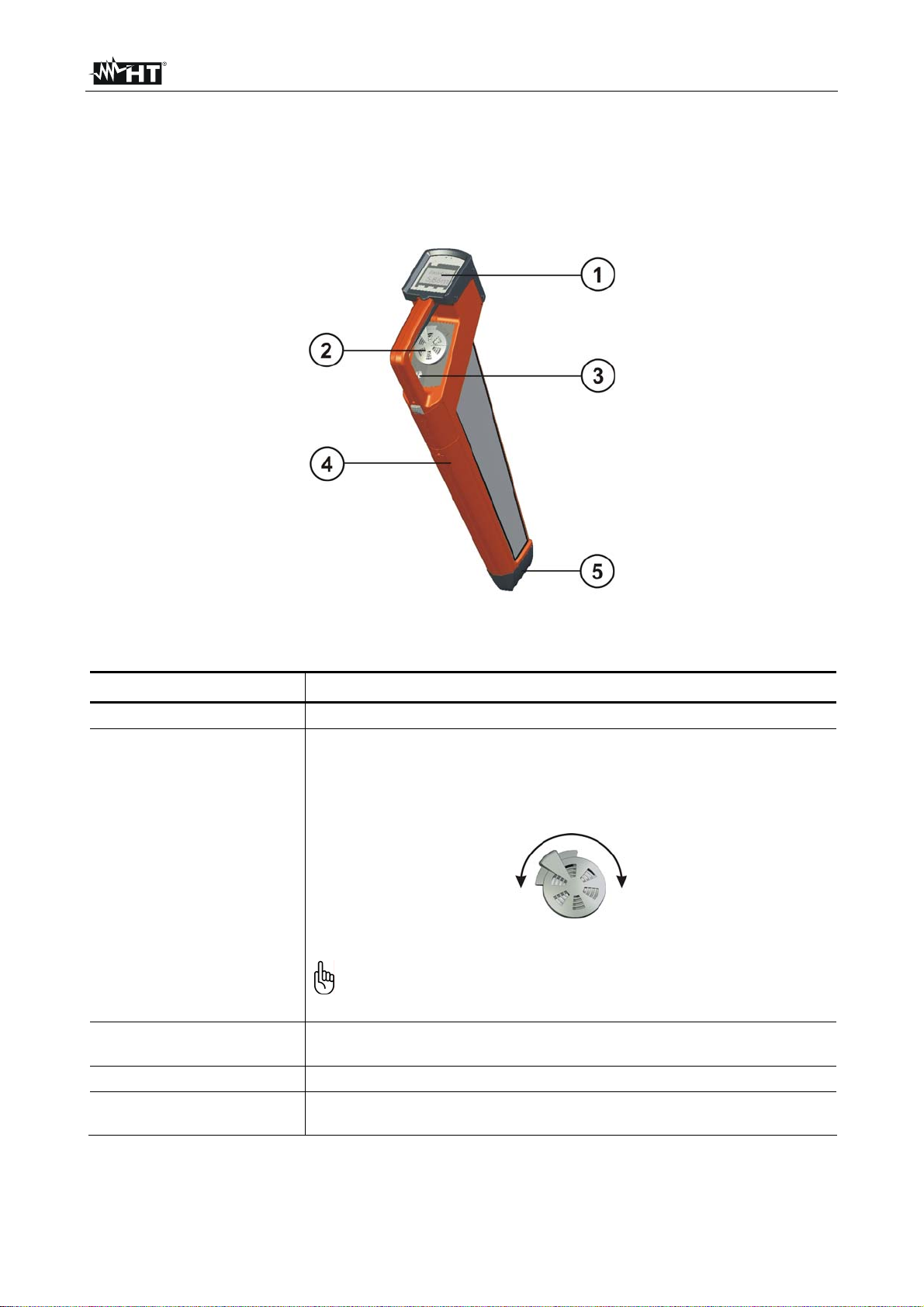
4.1.1 Description of the receiver RX5000
Fig. 1: Description of the receiver RX5000
Item Description
1
Control panel with display (see paragraph 4.1.2)
Speaker with volume control
The speaker plays back various acoustic signals (e.g. beeps
with modulating pitch relative to the signal strength)
2
Quieter Louder
When the receiver is switched on, the volume is set at a
standard level. The receiver will only start with the volume
at a different level if the volume has been manually
increased before switching off the receiver
3
Headphone jack
To connect headphones with a 3.5 mm plug connector
4 Battery compartment
5
Floor cap
This replaceable floor cap serves to protect the housing
EN - 4
Page 6
HT-5000
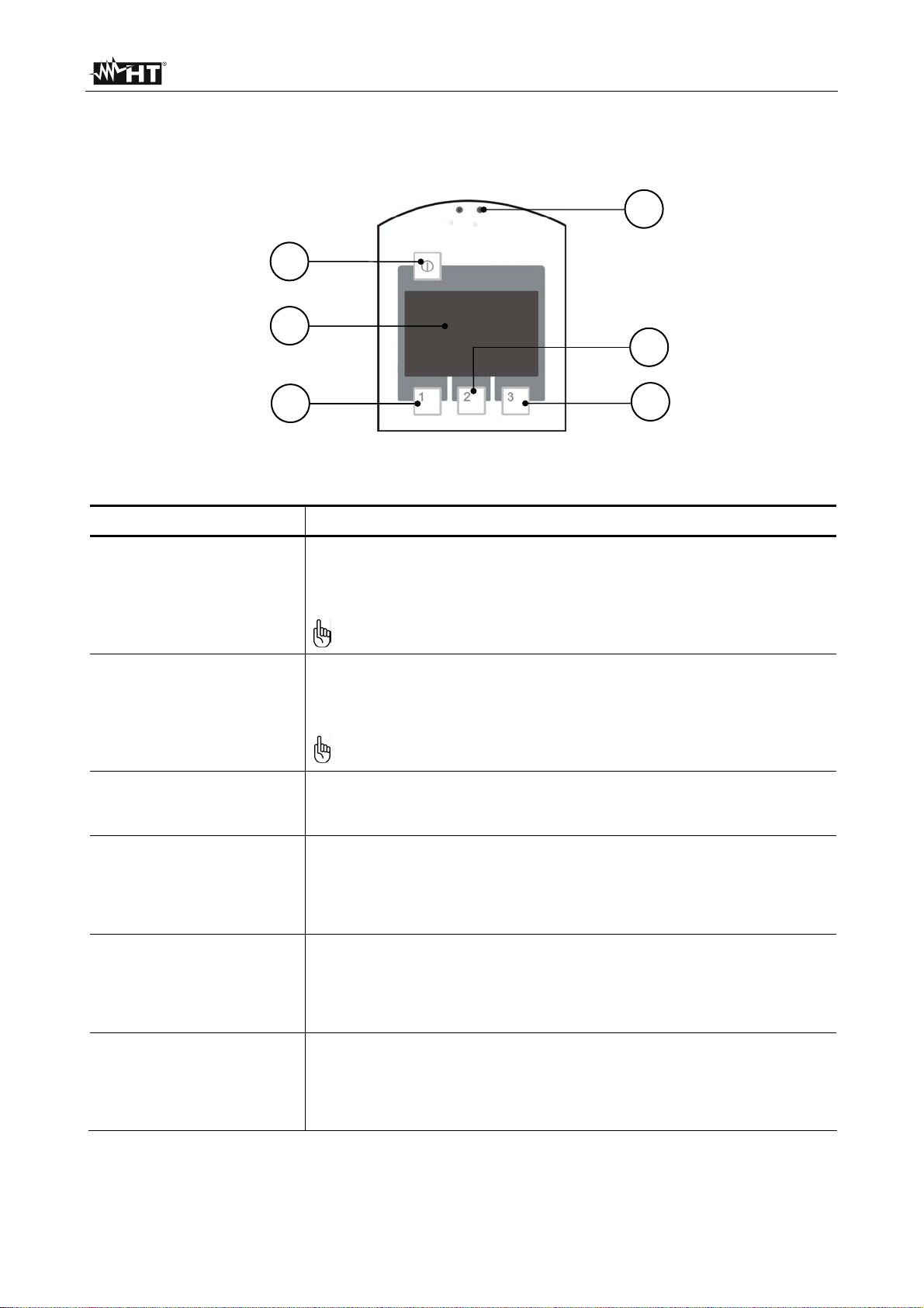
4.1.2 Display and control panel of RX5000
1
2
3
5
4
6
Fig. 2: Display and control panel of RX5000
Item Description
Light sensor
Light sensitive photo cells to automatically regulate the display
1
lighting
The display lighting can be manually activated for one
minute by briefly covering the light sensor
On/Off switch
By quickly pressing this button the receiver can be switched on
2
or off
The RX5000 will switch off automatically if no functions are
carried out within 7 minutes of being switched on
Display
3
Provides a visual indication of reception strength, line depth,
mode of operation, battery status and menu items
Function key 1
4
Depending on the status of the system, this button is used to:
• Manually decrease reception sensitivity
• Start measuring depth
Function key 2
5
Depending on the status of the system, this button is used to:
• Adjust reception sensitivity
• Start measuring depth
Function key 3
6
Depending on the status of the system, this button is used to:
• Select the mode of operation / receiving frequency
• Manually increase reception sensitivity
EN - 5
Page 7
HT-5000
4.1.3 Description of transmitter TX5000
The TX5000 transmitter is distinguished by the following features:
• Inductive coupling of the signal using the integrated antenna or transmitter clamp
• Direct (galvanic) coupling of the signal using connected equipment (such as the
measurement cable and power socket adapter)
• Two-step adjustable transmission power (0.1W / 0.5W)
• Selectable signal output continuous or pulsed
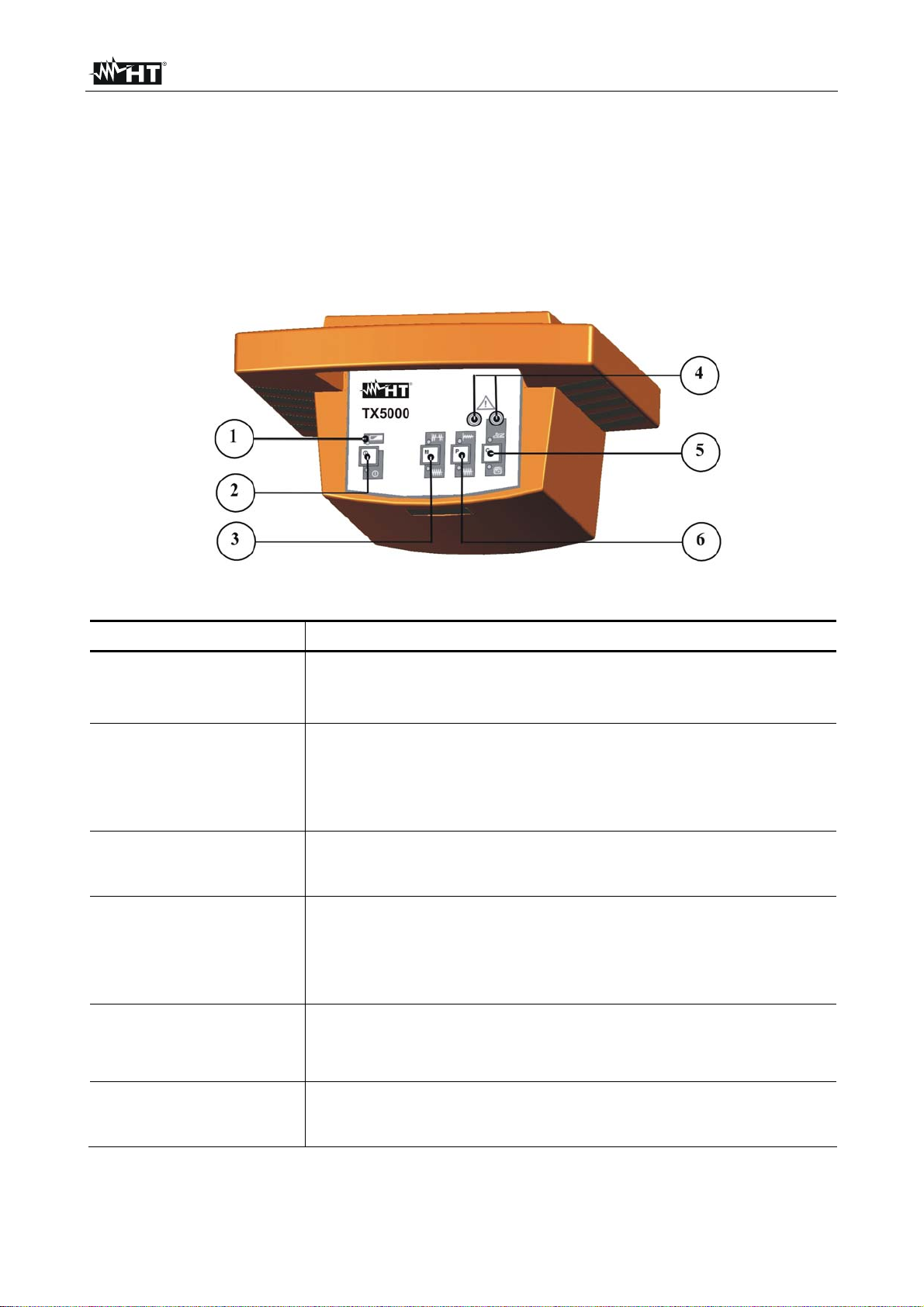
Fig. 3: Front panel of transmitter TX5000
Item Description
Battery status indicator
1
When the battery status LED blinks in red, the batteries need
to be replaced
On/Off switch
By quickly pressing this button the TX5000 can be switched on
2
or off.
All appropriate LED’s blink when the transmitter is on,
depending on operating function
Signal type function key
3
This key is used to switch between continuous and pulsed
signal output
Jacks for connecting accessories
These jacks are used to create a direct galvanic connection
4
with the target line or to create a connection using a special
connection set (e.g. 100mm transmitter clamp or house
connection set)
Mode function key
5
This key is used to switch between inductive and direct signal
coupling (galvanically or via transmitter clamp)
Signal strength function key
6
This key is used to select one of two signal strength levels
(0.1W or 0.5W)
EN - 6
Page 8
HT-5000
4.2 CONNECTION AND INITIAL USE OF TRANSMITTER TX5000
4.2.1 Transmitter signals and operation modes
The type and strength of the output signal can be configured by the user as follows to
meet the specific requirements of either the line to be located or the site to be surveyed:
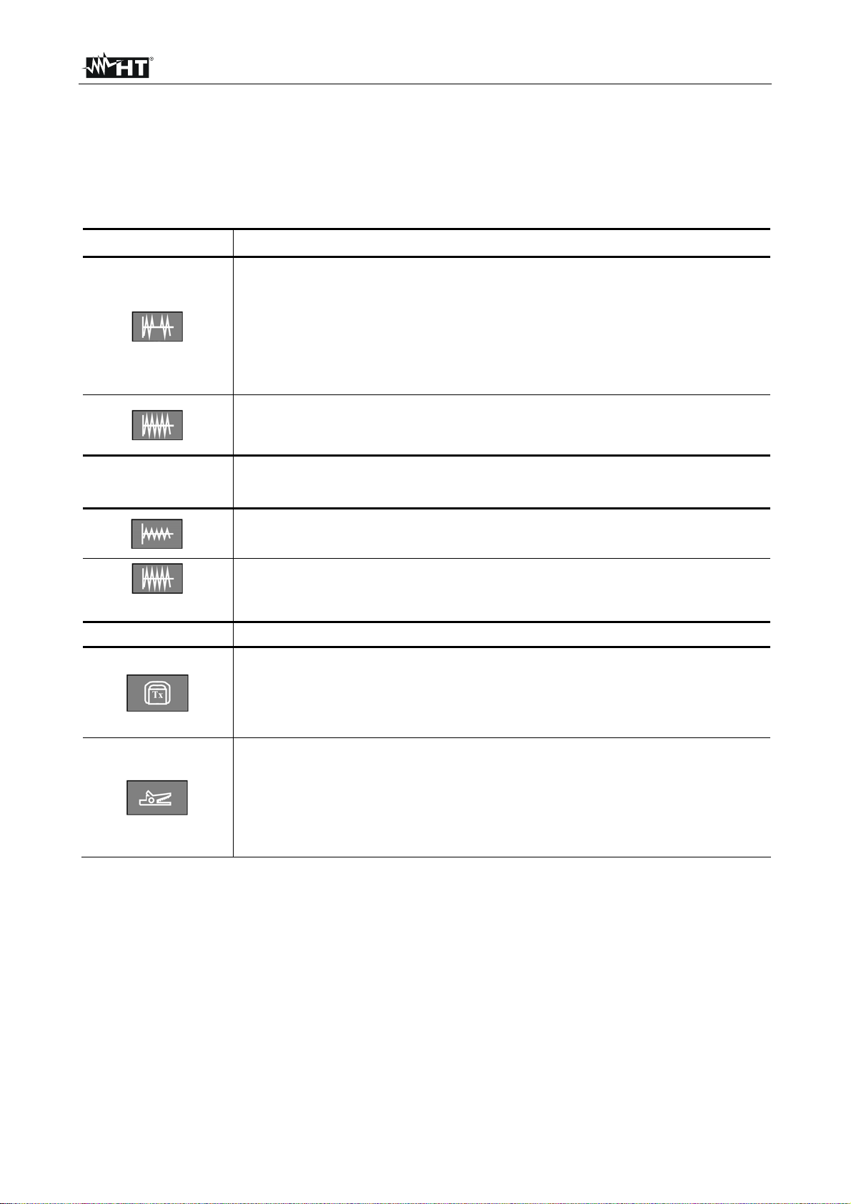
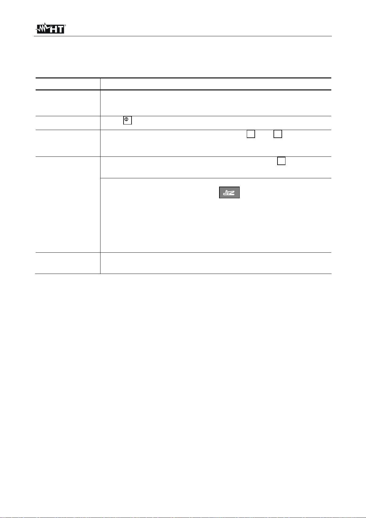
Symbol Signal type
Pulsed signal
As it is more easily distinguished from other signals, the pulsed signal
is helpful for locating when there is interference within the frequency
range of the transmitter. This also helps to conserve the batteries
Depth measurements cannot be made using a pulsating signal
Continuous signal
This signal type has to be activated before a taking a depth
measurement
Symbol Signal strength
Low output signal strength (0.1W)
Low signal strength conserves the batteries
High output signal strength (0.5W)
Symbol Operation modes
Inductive connection
In this mode of operation the transmitter's signal is emitted through
the integrated antenna and is thereby inductively coupled with any
metallic lines located within a certain radius
Direct connection
In this mode of operation the signal is directly coupled with a metallic
line via the measurement cable which is connected to the jacks on
the front panel of the transmitter. Transmitter clamps, alligator clips or
power socket adapters (for example) may be used to connect the
measurement cable to the lines
EN - 7
Page 9
HT-5000
4.2.2 Options for direct and inductive signal coupling
CAUTION
If the transmitter is connected to electrical service cables, it has to be
considered that the device is designed to achieve CAT II / CAT III 440 V and
CAT IV 300 V with Class 2 protection (double insulation) according to IEC / EN
61010-1. This means that the maximum voltage between the two terminals
must not exceed 440 V in measurement categories CAT II / CAT III and 300 V
in measurement category CAT IV
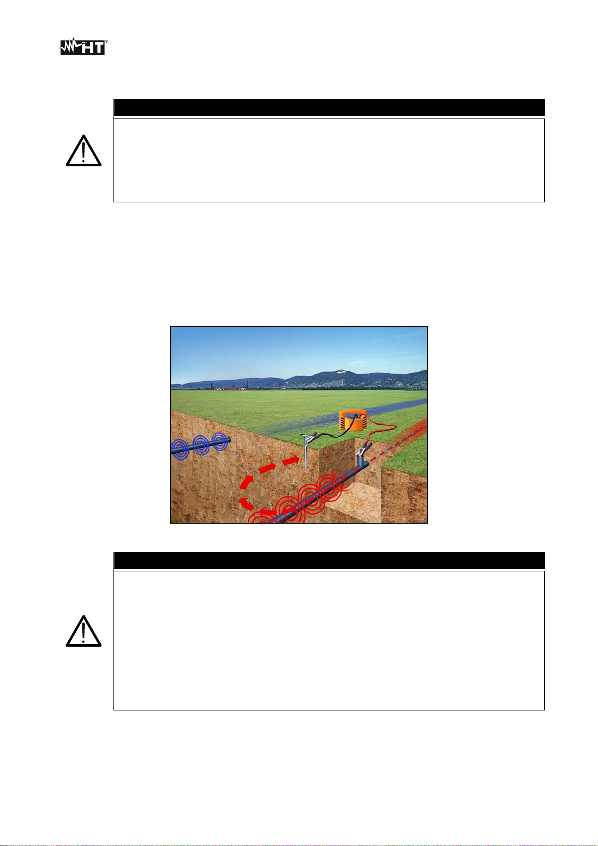
4.2.2.1 Direct coupling on cables and pipes
Direct galvanic coupling is practical for cables which are easily accessible and free of
current. The method of connection is dependent upon the position and nature of the lines
(e.g. insulation, cable conduit, accessibility of the cable ends).
Direct coupling presents a reliable option for selective cable location, as the signal can be
coupled onto a specific cable with virtually no loss.
The following illustration shows an example of direct coupling:
Fig. 4: Direct coupling on cables and pipes
CAUTION
If the lines being located are energised, the following five safety precautions
should be taken before connecting the transmitter:
1. Disconnect power supply
2. Secure against reconnection
3. Check for presence of current
4. Make earth connection and short circuit of parts
5. Cover or block access to adjacent components which are energized
If the system cannot be de-energized the use of the inductive coupling
clamp is possible to perform the location of objects
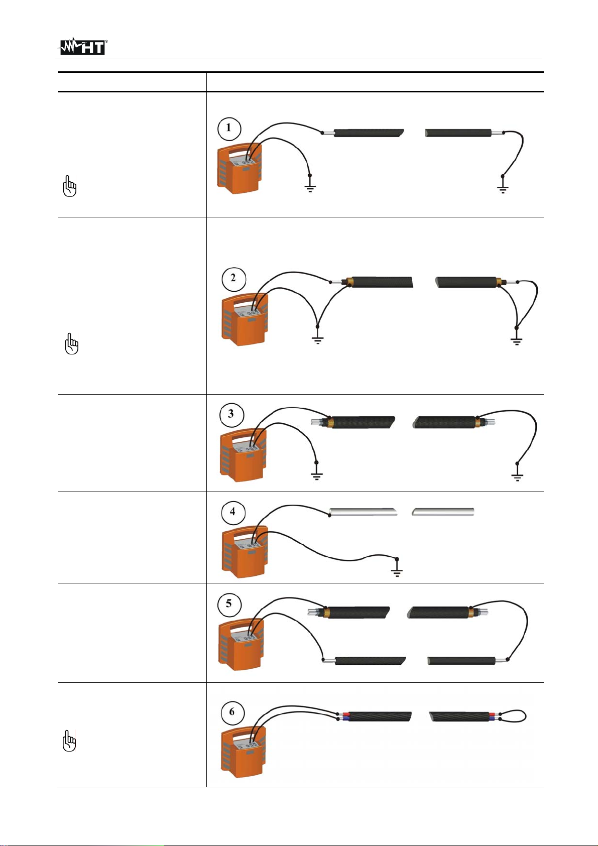
The following table explains various basic principles of direct galvanic coupling.
EN - 8
Page 10
HT-5000
Application Principle of coupling
Single-wire lines or pipes (with
or without insulation against
earthing)
The distance between the earth
spike and the ends of the
connected lines should be as great
as possible
There is a danger of the return
current flowing through the
earth into adjacent lines, which
could result in their path being
follow
Single-wire cable with metallic
screen and earthing insulation
Short circuit between internal
conductor and screen at the end of
the cable with earthing at the
beginning and end of the cable as
well
If the earth connections made
are unfavourable, the current
in the internal conductor and
the return current in the screen
will cancel each other out.
Under certain circumstances
this can prevent the cable from
being detected. Alternatively, a
connection without an earth
connection can also be made
Multiple-wire cable (internal
conductor connected or
disconnected) with metallic
screen and earthing insulation
verso terra
Same application as in example 1
Metallic conduit (with or without
insulation against earthing)
The earth spike and the conduit
should be spaced as far apart as
possible. Under certain
circumstances, optimum
positioning of the earth spike may
require several attempts
If a return wire is available
The spacing of the return wire
should correspond to at least
10 times the depth of the line being
located
Pair of wires (with or without
screen) with short circuit at the
end of the cable
Adjacent conductors
horizontal Ö
Minimum of the reception
signal
vertically Ö
Maximum of the reception
signal
EN - 9
Page 11
HT-5000
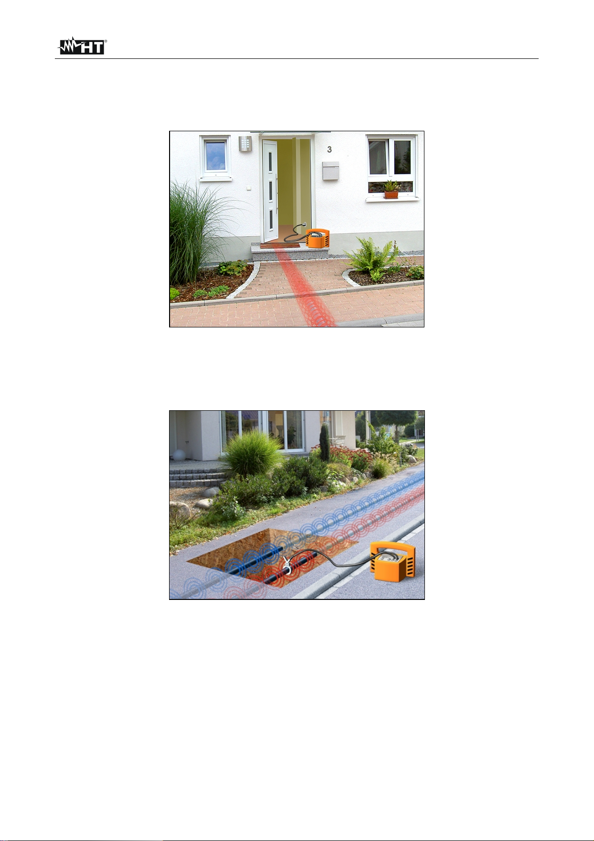
4.2.2.2 Coupling with special accessories
The signal from the transmitter can be directly coupled into plug sockets, antenna
connections coax and telephone jacks with the aid of a suitable adapter cable (Cod.
890008852). In doing so, it is not necessary to disconnect the lines.
Fig. 5: Couplng via adapter cable
The transmitter signal can be coupled onto easily accessible cables with the aid of a
100mm transmitter clamp (Cod. 820005314). In doing so, it is not necessary to disconnect
the cables
Fig. 6: Coupling via transmitter clamp
By ensuring that the transmitter clamp is completely closed around the cable, only a small
leakage field will be generated. This can significantly reduce the unwanted coupling of the
signal onto neighbouring lines.
Ideally the cables will be grounded at both ends, but even if they are not grounded at one
end, selecting high power transmitter output will assist easy location
EN - 10
Page 12

HT-5000
A
4.2.2.3 Inductive signal coupling
For lines which are not easily accessible, the signal from the transmitter has to be
inductively coupled via the integrated antenna. The inductive coupling of the signal is
highly recommended if unknown lines are to be located (e.g. at a construction site).
To determine the orientation of a specific line, the transmitter has to be positioned directly
above the presumed line as shown in Fig. 7. In doing so, the best signal coupling is
achieved when the handle of the transmitter housing is aligned with the presumed lay of
the line
Fig. 7:Inductive signal coupling
CAUTION
When locating lines using inductive signal coupling, the following guidelines
should be observed:
s the signal can be coupled onto other conductors when using inductive
•
coupling, direct coupling of the transmitter is always preferable when
locating lines selectively. Inductive signal coupling should only be opted for
in cases where the line being located is not easily accessible (see
paragraph 4.2.1 and 4.2.2)
• While taking measurements, make sure that a distance of at least 15m is
always maintained between the receiver and transmitter in order to prevent
the coupling of the transmitter's signal through the air
• When searching for unknown lines at a site, the position of the transmitter
has to be changed at least once by one metre and 90°
• It is also a good idea to position the transmitter at visible cable ends such as
at distribution boxes or light poles
EN - 11
Page 13

HT-5000
p
Under certain circumstances lines at lower depths can 'hide' deeper, adjacent lines, thus
making it more difficult to locate them.
In such cases, the transmission characteristics of the transmitter TX5000 can be fully
utilised and the lines which have already been located can be masked out (see Fig. 8)
Fig. 8: Masking-out lines
Line with weaker
inductive coupling
Line with good
inductive cou
ling
Follow the steps listed below in order to locate lines by masking-out adjacent lines
Step Action
Use the RX5000 and TX5000 to locate and pinpoint a buried line (see
1
paragraph 4.3.2)
With the RX5000 rested on the ground straight above the located
2
line, ask a colleague to place the TX5000 on its back (see Fig. 8)
nearby the line path (at least 15m away from the receiver)
Slide the TX5000 across the line until the signal strength bargraph is
lowest, indicating that the transmitter is directly above the line which,
thus, is masked-out
3
Note that adjacent lines may not be parallel with the first cable
route, so sweep the receiver around in a circle about 10m - 15m
radius from the transmitter, with the handle pointing towards the
transmitter. Any metallic lines within 2.5m of the transmitter will be
coupled with the transmitted signal
Pinpoint and determine the direction of any buried lines (see
4
paragraph 4.3.1.2)
EN - 12
Page 14

HT-5000
4.2.2.4 Signal coupling in non-metallic pipes
With the aid of the FlexSonde GOK50-R the transmitter's signal can be transmitted
through non-metallic pipes, as shown in the picture below:
Fig. 9: Signal coupling in non-metallic pipes
Alternatively, any other active probe (e.g. a camera probe) with adequate transmitting
frequency can be located using the receiver. For a detailed description, please refer to the
manual of the respective product.
When locating non-metallic pipes, the following guidelines should be observed:
• Contrary to the line location, a probe location has to be performed in perpendicular
position to the probe, i.e., the handle of the receiver has to be hold at right angle to the
probe
• Practice locating the probe or FlexSonde head before pushing it into the drain or duct.
• Strongest signal will be detected when the receiver is above and perpendicular to the
probe (as shown in Fig. 9)
The signal transmitted by the probe results in three signal maxima on the ground surface
level. Typically, there is a smaller maximum in front of the actual signal maximum and one
behind it.
For this reason, it should be always evaluated whether there are further signal maxima in
front of or behind the detected signal maximum. An accurate depth determination can only
be performed directly above the actual (highest) signal maximum.
If the receiver is operated in automatic sensitivity level adjustment mode, these lower
signal maxima are usually masked-out
EN - 13
Page 15
HT-5000
4.2.3 Initial use of the transmitter TX5000
Follow the steps listed below in order to prepare the transmitter to search for lines in
conjunction with the receiver:
Step Action
Connect the transmitter to the line to be located using the most
1
suitable method, or place the transmitter on the site to be searched
see paragraph 4.2.2
2
3
Press to switch on the transmitter
Select the desired output signal using the and function keys
M P
(see paragraph 4.1.3)
A green LED indicates that the respective setting is active
Select the desired mode of operation using the button (see
C
paragraph 4.1.3)
Result:
4
In Direct mode, an LED next to the
good the connection is to the connected line:
symbol indicates how
• Green blinking: good (low-resistance) connection
• Alternating red and green: sufficient connection
• Red blinking: poor/no (high-resistance) connection
As described in paragraph 4.3.1 use the RX5000 to locate metallic
5
conductors
EN - 14
Page 16
HT-5000
4.3 USE OF RECEIVER RX5000
4.3.1 Modes of operation for the receiver RX5000
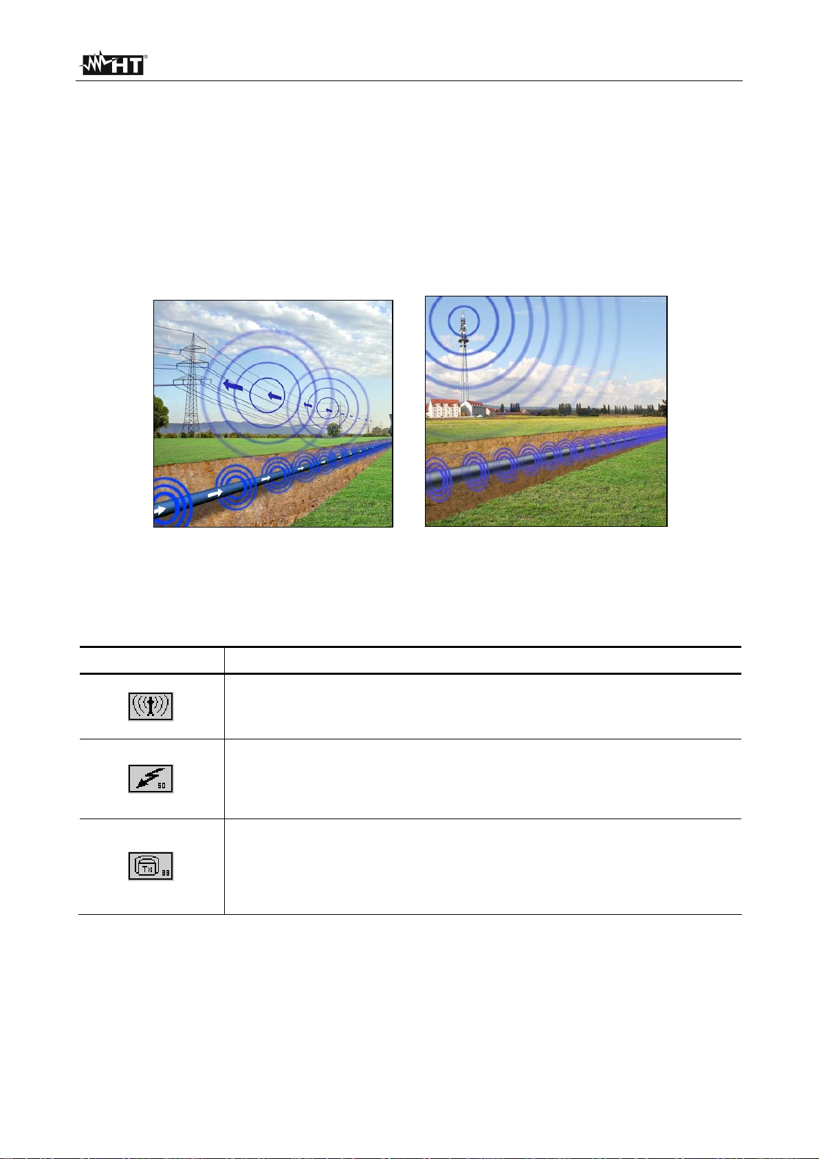
If a TX5000 transmitter is not available, a site can also be probed by means of passive line
location.
The RX5000 receiver is capable of detecting radio signals in the frequency range between
15kHz to 23kHz as well as power signals in the frequency range between 50/60Hz.
The following pictures illustrate how each of the signals couple onto conductors buried in
the ground:
Fig. 10: Use of receiver RX5000
The two options explained above for passive location together with the options of active
location with a transmitter or a probe transmitting a signal with an appropriate frequency
result in the following modes of operation:
Symbol Mode of operation
RADIO
For locating cables which are carrying VLF reradiated radio signals
POWER GRID
For locating mains power supply cables, through which current with a
grid frequency is flowing
TRANSMITTER
For locating cables or pipes, onto which the signal from an active
transmitter is coupled. The figure indicates the currently selected
frequency which has to correspond to the frequency of the transmitter
TX5000
EN - 15
Page 17
HT-5000
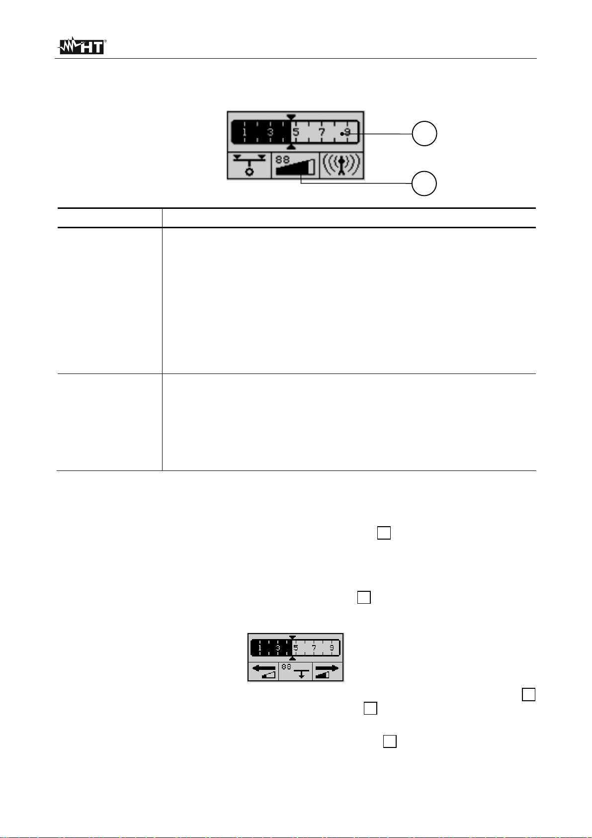
4.3.1.1 Regulating the sensitivity level to match the reception signal strength
Reception signal strength and sensitivity are shown in the following segments of the
display:
1
2
Item Mode of operation
Reception signal display bargraph
The strength of the reception signal is represented by this bargraph
scale. These are relative values which are based on the sensitivity
level set in the receiver
The triangles (▲▼) above and below the scale are a visual marker
1
for maximum values. They move towards the right as long as the
signal strength increases and continue in this direction until it either
levels off or decreases. The maximum marker remains in this position
for 3 seconds and thus provides the user with a helpful visual aid for
determining the maximum signal strength
Sensitivity display (gain level in %)
The sensitivity level set in the receiver (which coincides with the total
spectrum which the receiver is capable of processing) is represented
2
by this scale. The higher the level of sensitivity is set, the more
capable the receiver is of detecting weaker signals.
The numeric display above the bars shows the utilisation factor as a
percent
Should the scale for reception signal strength bargraph provide virtually no indication, or
the display is completely utilised, either a manual or automatic adjustment of the sensitivity
level has to be made.
To start an automatic sensitivity level adjustment, the
¾
2
button has to be pressed
once. The sensitivity level of the receiver will be automatically adjusted so that the
strength of the signal currently being received will be optimally displayed (fill half of the
scale)
¾ To start a manual sensitivity level adjustment, the
2
button has to be pressed for
about 2 seconds. The following indicator will appear in the display:
¾ Now the sensitivity of the receiver can be decreased by one percent by pressing the
button, or increased by one percent by pressing the button. This process can be
accelerated by holding down the respective button
¾ To exit the manual sensitivity level adjustment menu, the
1
3
2
button has to be pressed
for two seconds. By pressing the button only short, the depth measurement process will
begin
EN - 16
Page 18
HT-5000
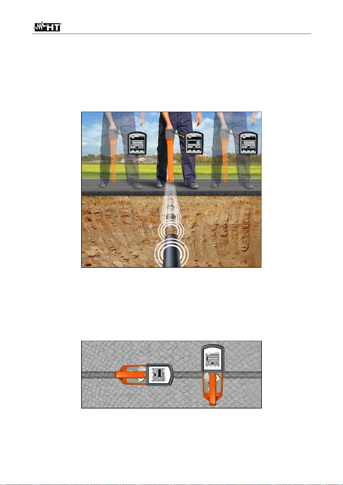
4.3.1.2 Handling the receiver and locating the line
In order to be able to determine the position and orientation of a metallic conductor, the
following rules should be internalised and applied when locating lines.
As shown in Fig. 11 the receiver should always be held in front of the body in an upright
position and as close to the ground as possible. When the transmitter is brought directly
over a metallic conductor, the maximum signal strength will be measured. If the receiver is
moved away from the conductor towards the side and is not rotated while doing so, the
signal will drop off proportionately
Fig. 11: Handling the receiver RX5000
The alignment of the receiver in relation to the orientation of the conductor (the antenna
being the starting point of alignment) has the following effects on the reception signal
strength:
• Receiver in line with the conductor Ö maximum signal strength
• Receiver perpendicular to the conductor Ö minimum signal strength
Fig. 12: Alignment of the receiver RX5000
EN - 17
Page 19
HT-5000
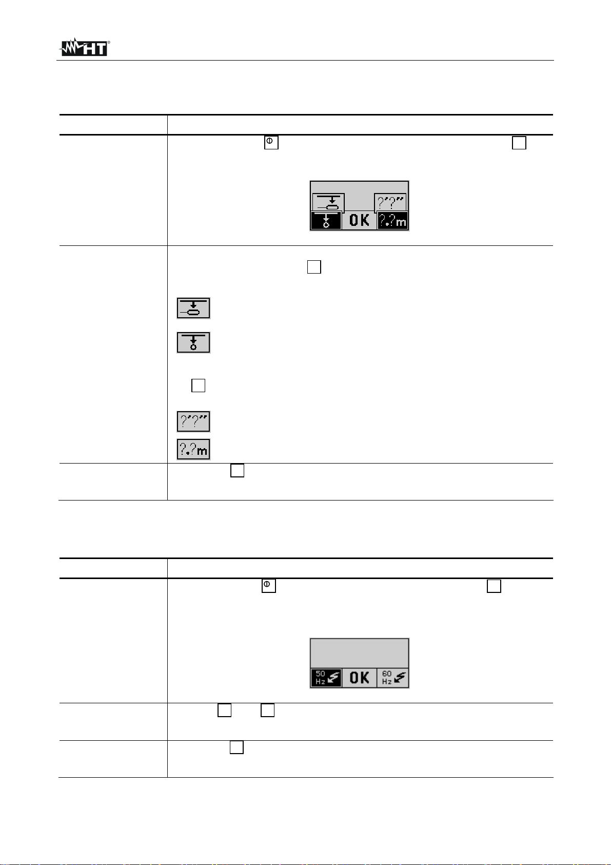
4.3.1.3 Changing of the system settings
Proceed as follows to change the settings:
Step Action
Briefly press the button while continuing to hold down the key
until an audible signal is heard. The following image is display:
1
Now one of the following depth measurement processes may be
selected by pressing the key:
Select this symbol if you want to determine the depth of a
probe which has been pushed into a non-metallic pipe
Select this symbol if you want to determine the depth of a
2
line, the signal of an active transmitter is coupled onto
Now a unit of length used by the system may be selected by pressing
3
the key:
1
1
Feet (ft)
Metre (m)
2
3
Press the key to save the settings. The changes will remain in
effect even after the receiver is switched off and back on again
Proceed as follows to change the receiving frequency of operation modes with more than
one possible frequency:
Step Action
Briefly press the key while continuing to hold down the key until
3
an audible signal is heard. The selectable frequencies are now visible
in the display:
1
3 1
2
3
Use the and keys to switch between 50 and 60Hz. The active
setting is marked with a black background
Press the key to save the settings. The changes will remain in
2
effect even after the receiver is switched off and back on again
EN - 18
Page 20
HT-5000
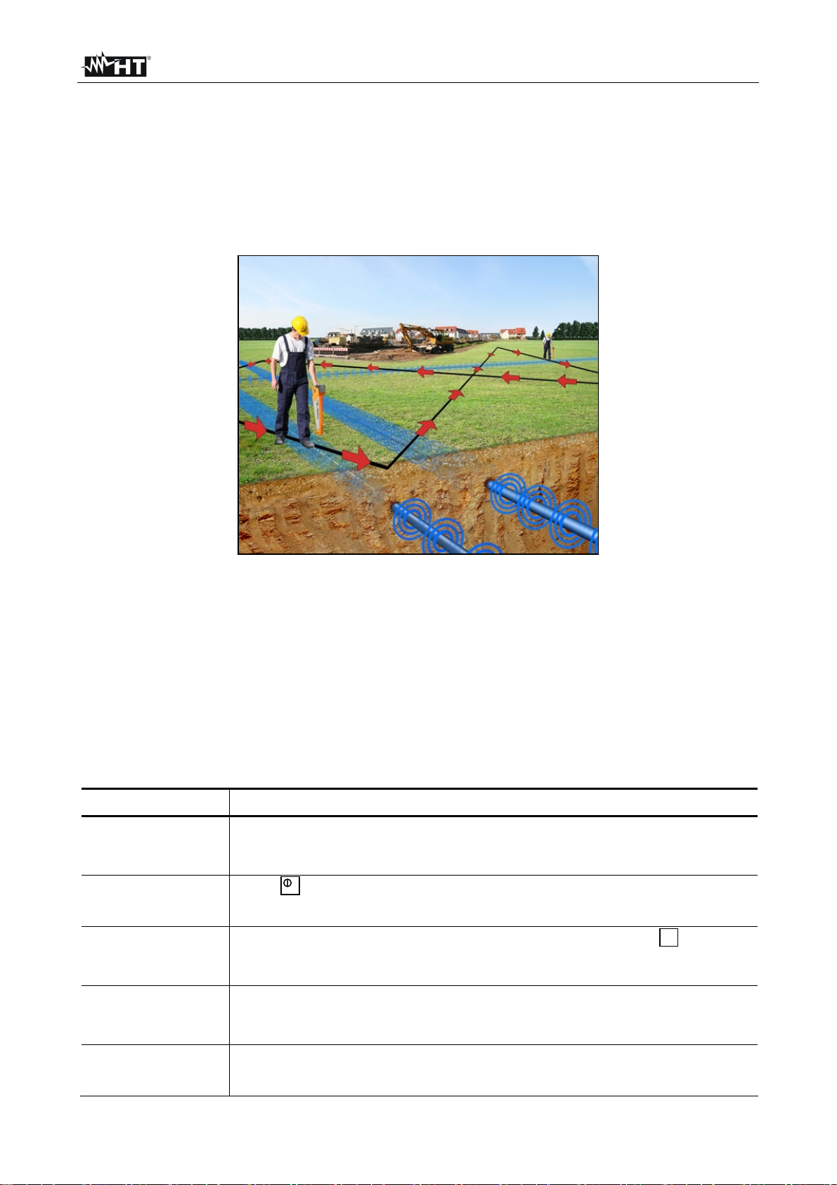
4.3.2 General site surveying
A general site probing urgently needs to be conducted and there is inaccurate or no
information available as to the location and orientation of metallic conductors on a site
planned for construction (e.g. excavation work).
When a site is to be searched for unknown conductors, a systematic approach should be
taken. The following picture illustrates how to proceed:
Fig. 13: General site surveying
Carry out a passive survey in POWER GRID and RADIO modes using a grid search
pattern to cover the site and locate conductors in all directions
If the site will be surveyed with the aid of the TX5000 transmitter used on induction, the
position of the transmitter should be changed by at least one metre and 90° after the first
sweep of the site and the site should be probed again in the same manner. The minimum
spacing of 15m between the transmitter and receiver must always be maintained
Follow the steps below when probing a site for unknown metallic conductors:
Step Action
If the site will be searched with the aid of the TX5000 transmitter, it
1
needs to be configured as described in paragraph 4.2.3 before
proceeding
Press to switch on the receiver RX5000
2
3
3
Select the desired mode of operation by pressing the key (see
paragraph 4.3.1). The symbol for the currently selected mode of
operation is shown in the lower right-hand corner of the display
Pace off the site as previously described and make a grid search of
4
the site (see Fig. 13). Adjust the sensitivity of the receiver as needed
if the signal level is too strong / weak (see paragraph 4.3.1.1)
When a conductor is located, pinpoint the strongest signal (see
5
paragraph 4.3.1.2) and mark the location
EN - 19
Page 21

HT-5000
4.3.3 Determining the direction of a line
Step Action
If the direction of the conductor will be determined with the aid of the
TX5000 transmitter, couple the transmitter's signal onto the metallic
1
conductor in such a way that there is as little signal loss as possible
(see paragraph 4.2.2 and paragraph 4.3.1)
2
3
Press to switch on the receiver
Select the desired mode of operation by pressing the key (see
3
paragraph 4.3.1). The symbol for the currently selected mode of
operation is shown in the lower right-hand corner of the display
Hold the receiver perpendicular to the position of a known metallic
4
conductor, e.g. above a location which was marked during the
probing of the site (see paragraph 4.3.2)
Rotate the receiver (through its own axis) over this location until the
maximum signal strength is indicated (see paragraph 4.3.1.2)
5
Result: The receiver is in line with the conductor when it is positioned
where the signal is strongest, which is prerequisite for determining
the direction of the line
To determine the path over an extended distance, proceed by
moving forward while maintaining the maximum signal strength. If the
signal becomes weaker, check that the conductor has not changed
direction or become deeper, move and/or rotate the receiver to the
left and right until the maximum signal strength is detected again.
6
The path of the metallic conductor should always be followed until it
exits the site being searched, and its path should be clearly marked
along the way with paint/chalk or marker flags
Adjust the sensitivity of the receiver as needed if the signal level is
too strong / weak. It is advisable to manually adjust the sensitivity
level (see paragraph 4.3.1.1)
EN - 20
Page 22
HT-5000
4.3.4 Determining the depth of a line
The RX5000 receiver has an automatic push key depth measurement feature. One
precondition is that a clear signal from the TX5000 transmitter is coupled onto the
conductor to be measured. For this procedure, the transmitter's signal has to be
continuous (not pulsed) (see paragraph 4.2.1).
In addition to this precondition, automatic depth measurement will only function when the
mode of operation of the receiver is set to TRANSMITTER. It will not function if set to
POWER GRID or RADIO
If these preconditions are not met, a rough estimate of the depth may be made using the
manual method
If the depth of a non-metallic pipe needs to be determined, the measurement has to be
made with aid of a probe, e.g. FlexSonde GOK50-R (see paragraph 4.2.2.4). In order to
accommodate the transmission characteristics of a probe, the RX5000 receiver has a
special depth measurement mode which has to be activated through the system settings
(see paragraph 4.3.1.3)
As a result, the way a depth measurement can be performed depends not only on the
active operation mode but also on how the depth measurement mode is set (Transmitter
or Probe). A symbol in the lower left of the display indicates which mode is currently
accessible
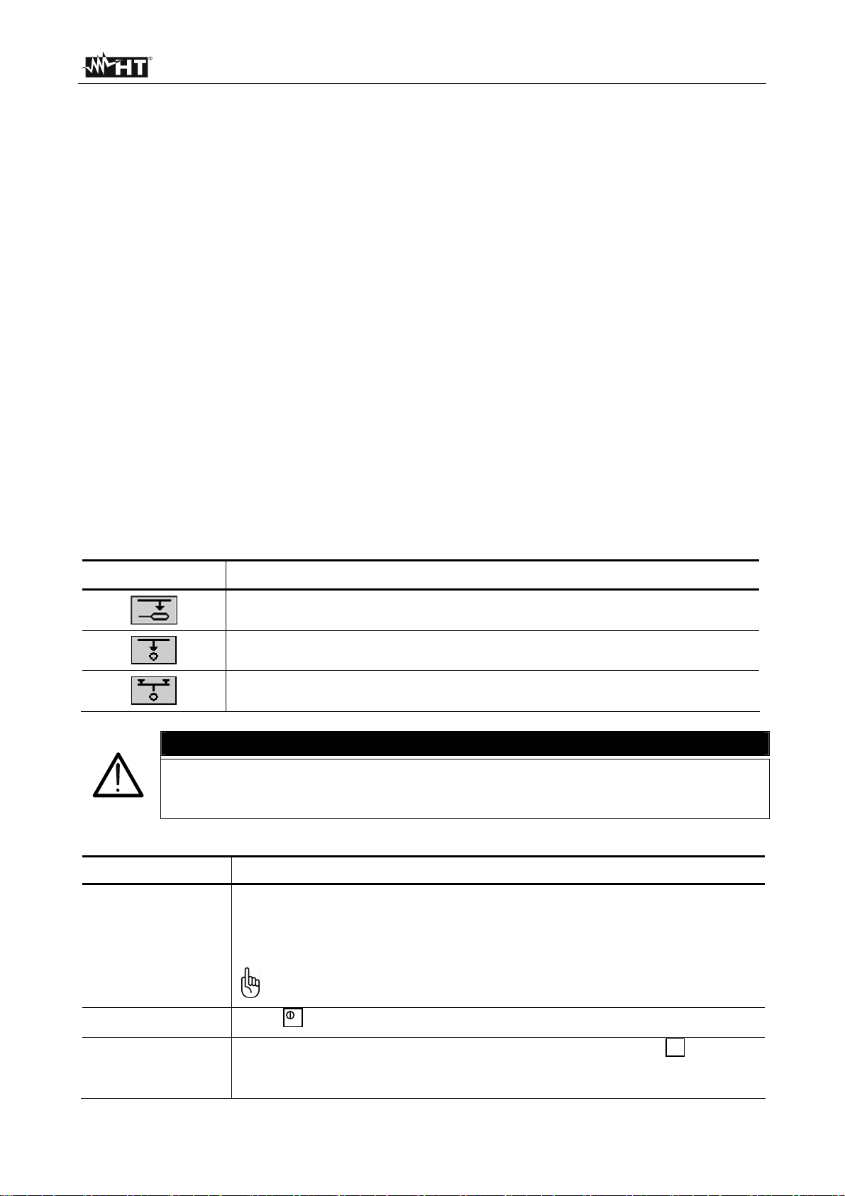
Symbol Description
For determining the depth of a probe which has been pushed into a
non-metallic pipe
For determining the depth of a line, the signal of an active transmitter
is coupled onto
For determining the depth of a line which carries radio signals or grid
frequency signals
ATTENZIONE
Even after the depth has been successfully determined, all excavation work
should be done with caution. This is particularly important if a rough estimate
Follow the steps below to determine the depth of a metallic conductor:
of the depth was made, as this can result in even greater deviations
Step Action
If the depth of the conductor will be determined with the aid of the
TX5000 transmitter, couple the transmitter's signal onto the metallic
conductor in such a way that there is as little signal loss as possible
1
(see paragraph 4.2.2 e paragraph 4.3.1)
Do not forget to set the transmitter to continuous signal, not a
pulsed signal when measuring depth
2
3
Press to switch on the receiver
Select the desired mode of operation by pressing the key (see
3
paragraph 4.3.1). The symbol for the currently selected mode of
operation is shown in the lower right-hand corner of the display
EN - 21
Page 23
HT-5000
With a steady grip, hold the receiver perpendicular to the position of a
known metallic conductor, e.g. above a location which was marked
4
during the site survey. The signal strength bargraph should show
zero (see paragraph 4.3.2). In doing so, the tip of the receiver should
touch the ground
Rotate the receiver (through its own axis) over this location until the
5
maximum signal strength is indicated (see paragraph 4.3.1.2)
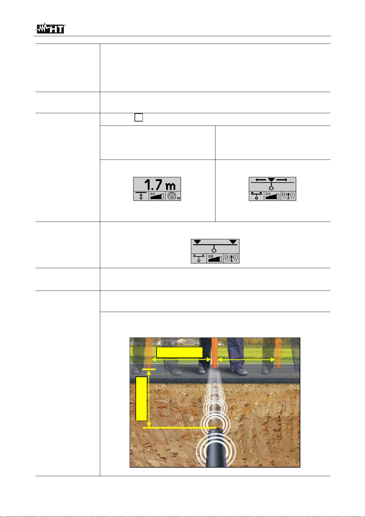
Press the button to begin measuring the depth
1
6
7
8
For automatic depth measure
(while working in TRANSMITTER
or PROBE mode)…
…the depth value is displayed (
The other steps can be skipped
For making a rough estimate of
the depth (while working in
RADIO or POWER GRID
mode)....
…the herewith symbol is shown
continue from step 7
Move slowly to one side until the following symbol appears in the
display and an acoustic signal sounds:
Mark this spot, then move in the opposite direction to the other side of
the line until the symbol appears in the display again
Mark this spot as well, then measure the distance between the two
spots
Result: Half the distance between the two spots corresponds
approximately to the depth of the line
Distance
9
Depth
EN - 22
Page 24
HT-5000
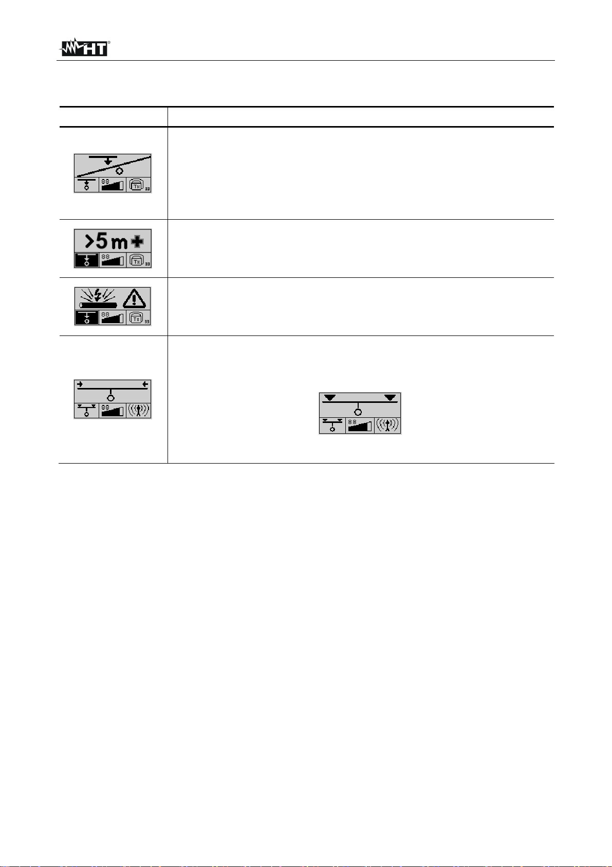
During the depth measuring process, the following symbols are used to notify the user
about certain characteristics and errors:
Symbol Meaning
For of one of the following reasons, the depth could not be
measured:
• The signal received was too weak or too irregular
• The receiver was not held steady enough during the measure
• The receiver was not positioned directly above the line at the
beginning of the process
The depth of the metallic conductor / probe exceeds the measuring
range (5m / 7m). Depth measurement cannot be performed
The depth of the metallic conductor amounts to less than 30 cm (1 ft).
Such conductors must be specially marked in order to prevent
damage during construction
The receiver was moved too far to the left or right while making a
rough estimate. Move in the opposite direction until the following
symbol appears
Proceed as described in step 8 on the previous page
EN - 23
Page 25
HT-5000
4.3.5 Functional test of the receiver
If problems or strange measuring results occur during a line location procedure, it may be
helpful to check the functionality of the receiver using the integrated self-test. This test may
provide information about possible malfunctions of the instrument. Preferably, the self-test
should be performed in an interference-free environment without live cables
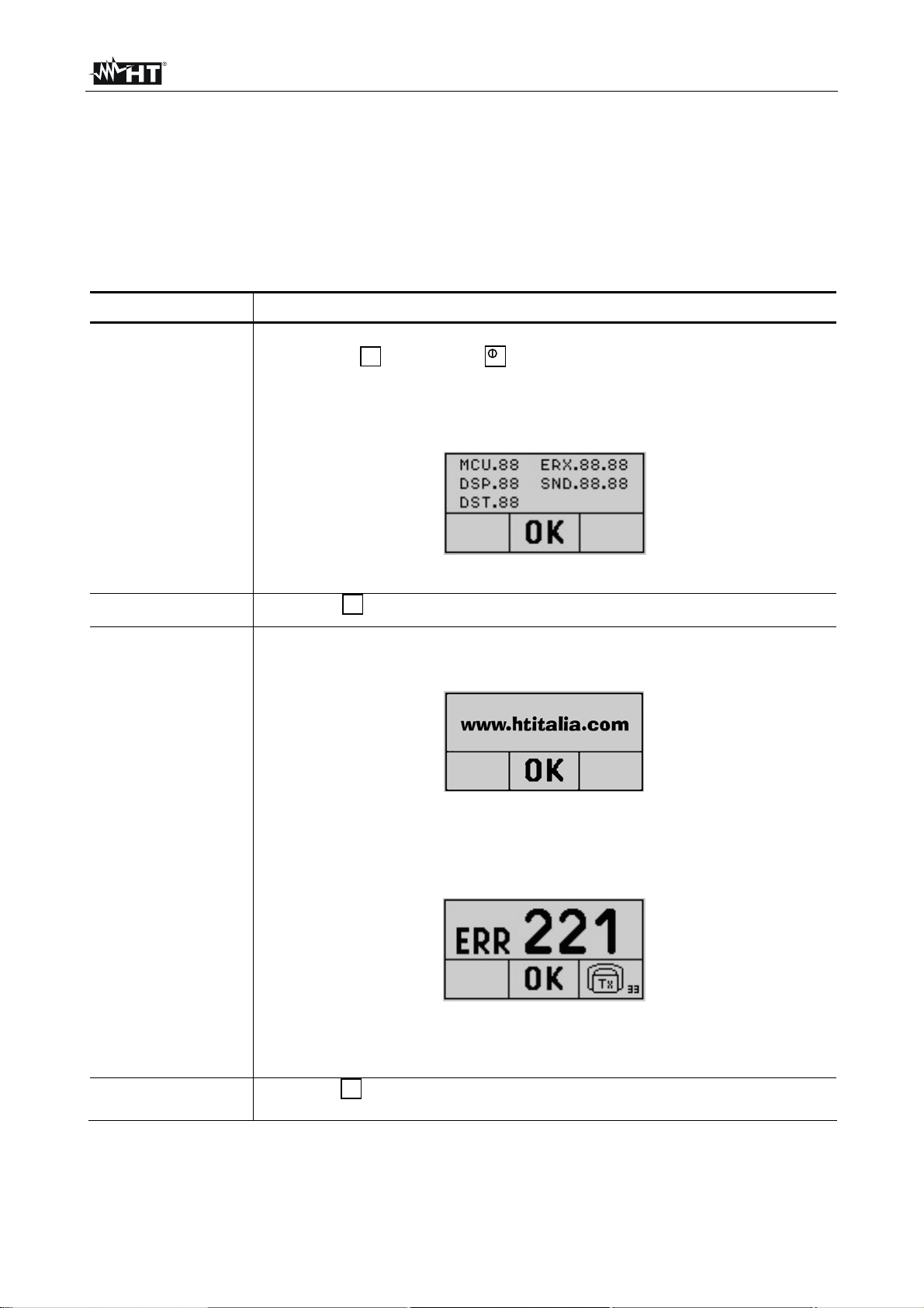
Proceed as follows to perform a self-test:
Step Action
1
2
Switch off the receiver RX5000. The test can be started by pressing
and holding followed by for at least 3 seconds
2
If the self-test is successfully accessed, the display should show the
software and hardware versions of the receiver components:
Press the function key to start the self-test
2
If the test is successfully passed without any problems, the display
shows the following information:
If a fault is recognized during the test, the self-test procedure is
3
terminated and the display indicates the respective error code (see
next page):
If this is the case, the error code should be forwarded to the service
department of HT ITALIA
2
4
Press the function key to exit the self-test
EN - 24
Page 26

HT-5000
Error code Description
000
201
Unimplemented frequency
Not enough battery power for the self-test procedure
Interferences too strong for the self-test procedure
210
In this case, the self-test should be repeated in an environment
with less interferences
220
230
240
250
Fault internal module L1. Contact service dept of HT ITALIA
Fault internal module L2. Contact service dept of HT ITALIA
Fault internal modules L1 and L2. Contact service dept of HT ITALIA
Generic fault. Contact service dept of HT ITALIA
EN - 25
Page 27
HT-5000
5 MAINTENANCE
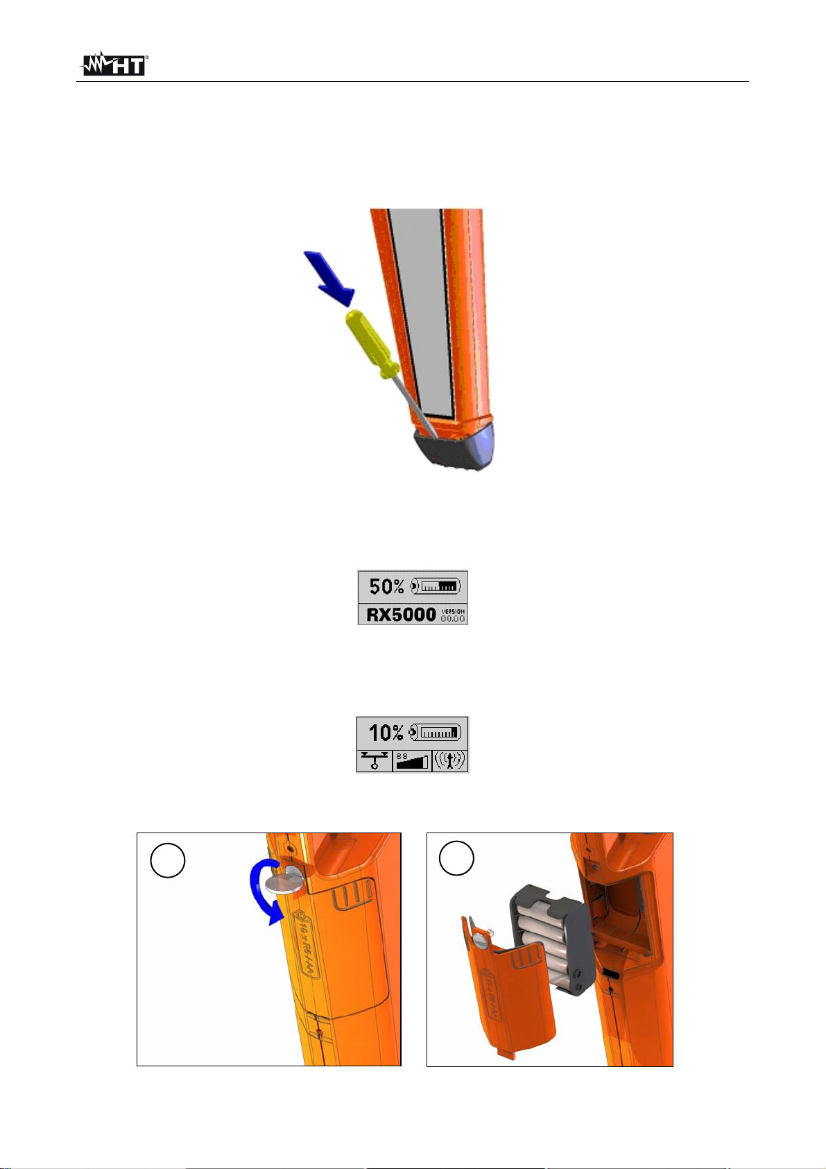
5.1 REPLACEMENT FLOOR CAP OF THE RECEIVER RX5000
The plastic floor cap, which prevents the tip of the receiver from being damaged, can be
easily replaced with the aid of a pointed object (e.g. screwdriver).
Fig. 14: Replacement of the floor cap
5.2 REPLACEMENT BATTERIES OF RECEIVER RX5000
The status of the receiver's batteries is checked upon start-up and indicated in the display:
The system regularly checks the battery strength as well. If battery capacity falls below 10
% of the threshold value, an audible warning signal is given and the current status of the
batteries is shown in the upper part of the display:
In order to replace the 10x1.5V batteries type AA, the battery housing must be removed
(e.g. using a coin) as described in the following illustrations
1
2
Fig. 15: Replacement internal batteries of RX5000
EN - 26
Page 28

HT-5000
5.3 REPLACEMENT BATTERIES OF TRANSMITTER TX5000
The batteries in the transmitter TX5000 have to be replaced as soon as the red LED
battery indicator starts to blink
Should this occur while the user is busy locating a line with the receiver, he/she will be
informed of the weak batteries via the reception signal:
Type of signal Normal signal Signal when batteries are weak
In order to change the 6x1.5 V batteries type LR20, both screws on the back of the
transmitter must be (e.g. with the aid of a coin) turned through ¼ turn (1) and the battery
tray must be pulled (2) (see Fig. 16). Please note that all the batteries are fitted in the
same direction
Fig. 16: Replacement batteries of TX5000
5.4 CLEANING
To clean the instrument use a soft dry cloth. Never use a wet cloth, solvents or water
5.5 END OF LIFE
CAUTION: this symbol indicates that equipment and its accessories shall be
subject to a separate collection and correct disposal
EN - 27
Page 29

HT-5000
6 TECHNICAL SPECIFICATION
6.1 TECHNICAL CHARACTERISTICS OF RECEIVER RX5000
Parameter Value
Frequency ranges
• Mode 1: Radio
• Mode 2: Power network
• Mode 3: Transmitter
Sensitivity
• Mode 1: Radio
• Mode 2: Power network
• Mode 3: Transmitter
Depth determination
• Depth range
• Resolution
• Accuracy (signal without disturb)
- Mode 1: Radio
- Mode 2: Power network
- Mode 3: Transmitter
15kHz ÷ 23kHz
50Hz / 60Hz
32.768kHz
Refer to a depth of 1m
> 20µA
> 7µA
> 5µA
…of a conductor …of a probe
0.3m÷5m (12in÷16ft)
0.1m
±20%rdg
±20%rdg
±5%rdg (up to 2m)
±20%rdg (2÷5m)
0.3m÷7m (12in÷23ft)
0.1m
±10%rdg (up to 2m)
±20%rdg (2÷7m)
Power supply
Battery life
Working temperature
• Operation
• Storage
Size (LxWxH)
10x1.5V batteries type IEC AA LR06
40 hours (for intermittent use with alkaline
batteries, 20 °C)
according to IEC/EN60068-1
-20 ÷ 55°C (-4 ÷ 131°F)
-30 ÷ 70°C (-22 ÷ 158°F)
660 x 252 x 99mm (26 x 10 x 4)”
Weight (included batteries) 2.5kg (5lb)
Mechanical protection
Dust and water protected
according to a IEC/EN60529
IP67 up to the lower edge of the battery
IP56 for all parts above this delineation
EN - 28
Page 30

HT-5000
6.2 TECHNICAL CHARACTERISTICS OF TRANSMITTER TX5000
Parameter Value
Transmitted power (switchable) 0.1W / 0.5W
Frequency
Power supply
Battery life
Working temperature
• Operation
• Storage
Category of measure
Size (LxWxH)
32.768kHz
6x1.5V batteries type IEC LR20
40 hours (for intermittent use with alkaline
batteries, 20 °C)
according to IEC/EN60068-1
-20 ÷ 55°C (-4 ÷ 131°F)
-30 ÷ 70°C (-22 ÷ 158°F)
CAT II / CAT III 440V, CAT IV 300V
260 x 255 x 140mm (10.2 x 10 x 5.5)”
Weight (included batteries) 1.7kg (3lb)
Mechanical protection
Dust and water protected
6.3 GENERAL SPECIFICATIONS
according to a IEC/EN60529
IP56
Parameter Value
Sinusoidal vibrations
Peak acceleration
Frequency
According to IEC / EN 60068–2–6
20m/s2
10Hz ÷150Hz
Free fall
Max. height (packaged)
Safety
Protection class
Insulation
Relative humidity
According to IEC/EN60068-2-32
80cm (weight up to10kg)
IEC/EN61010-1
III (according to IEC/EN61140)
Double insulation
max 93% at 30°C
6.4 ACCESSORIES
6.4.1 Standard accessories
• Transmitter TX5000 • 6x1.5V batteries IEC LR20
• Receiver RX5000 • 10x1.5V batteries IEC LR06
• 2 cables R/B banana + alligator clip, 2m • Carrying bag
• 1 cable black banana + alligator clip, 10m • User manual
• 1 earth metal probe
6.4.2 Optional accessories
• Flexi sonde set for locating non-metallic pipes – Cod GOK50-R
• Transmitter clamp, 100mm diameter for the inductive coupling – Cod. 820005314
• Set of cables (Shuko plug + cable with RJ11 + coax cable) – Cod. 890008852
EN - 29
Page 31

HT-5000
7 SERVICE
7.1 WARRANTY CONDITIONS
This instrument is guaranteed for one year against material or production defects, in
accordance with our general sales conditions. During the warranty period the manufacturer
reserves the right to decide either to repair or replace the product.
Should you need for any reason to return back the instrument for repair or replacement
take prior agreements with the local distributor from whom you bought it. Do not forget to
enclose a report describing the reasons for returning (detected fault). Use only original
packaging. Any damage occurred in transit due to non original packaging will be charged
anyhow to the customer.
The warranty doesn’t apply to:
• Accessories and batteries (not covered by warranty).
• Repairs made necessary by improper use (including adaptation to particular
applications not foreseen in the instructions manual) or improper combination with
incompatible accessories or equipment.
• Repairs made necessary by improper shipping material causing damages in transit.
• Repairs made necessary by previous attempts for repair carried out by non skilled or
unauthorized personnel.
• Instruments for whatever reason modified by the customer himself without explicit
authorization of our Technical Dept.
• Use not provided by the instrument's specifications or in the instruction manual.
The contents of this manual may not be reproduced in any form whatsoever without the
manufacturer’s authorization.
Our products are patented and our logotypes registered. We reserve the right to
modify specifications and prices in view of technological improvements or
developments which might be necessary.
7.2 SERVICE
Shouldn’t the instrument work properly, before contacting your distributor make sure that
batteries are correctly installed and working and replace them if necessary.
Should you need for any reason to return back the instrument for repair or replacement
take prior agreements with the local distributor from whom you bought it. Do not forget to
enclose a report describing the reasons for returning (detected fault). Use only original
packaging. Any damage occurred in transit due to non original packaging will be charged
anyhow to the customer.
The manufacturer will not be responsible for any damage to persons or things.
EN - 30
 Loading...