

Page 1

ENGLISH
User manual
Copyright HT ITALIA 2012 Release EN 1.01 - 14/05/2012
Page 2

HT401
Table of contents:
1. PRECAUTIONS AND SAFETY MEASURES ............................................................... 2
1.1. Preliminary instructions ..................................................................................................... 2
1.2. During use ......................................................................................................................... 3
1.3. After use ............................................................................................................................ 3
1.4. Definition of measurement (overvoltage) category ............................................................ 3
2. GENERAL DESCRIPTION ........................................................................................... 4
2.1. Measuring average values and TRMS values ................................................................... 4
2.2. Definition of true root mean square value and crest factor ................................................ 4
3. PREPARATION FOR USE ........................................................................................... 5
3.1. Initial checks ...................................................................................................................... 5
3.2. Instrument power supply ................................................................................................... 5
3.3. Calibration ......................................................................................................................... 5
3.4. Storage .............................................................................................................................. 5
4. OPERATING INSTRUCTIONS ..................................................................................... 6
4.1. Instrument description ....................................................................................................... 6
4.1.1. Description of the controls ................................................................................................................. 6
4.2. Description of function keys .............................................................................................. 7
4.2.1. RANGE key ....................................................................................................................................... 7
4.2.2. VoltSense key .................................................................................................................................... 7
4.2.3. MIN MAX key ..................................................................................................................................... 7
4.2.4. SMART HOLD key ............................................................................................................................. 7
4.2.5. Backlight key ............................................................................................................................... 7
4.2.6. MODE key ......................................................................................................................................... 7
4.3. Internal modes of instrument ............................................................................................. 8
4.3.1. PEAK/HOLD mode ............................................................................................................................ 8
4.3.2. AC+DC mode ..................................................................................................................................... 8
4.3.3. AutoV LoZ mode ................................................................................................................................ 8
4.3.4. Disabling the Auto Power OFF function ............................................................................................. 8
4.3.5. Wrong insertion indication ................................................................................................................. 8
4.4. Operating instructions ....................................................................................................... 9
4.4.1. DC Voltage measurement ................................................................................................................. 9
4.4.2. AC Voltage measurement and Frequency ....................................................................................... 10
4.4.3. AC Voltage measurement with low input impedance ...................................................................... 11
4.4.4. DC Current measurement ................................................................................................................ 12
4.4.5. AC Current measurement and Frequency ....................................................................................... 13
4.4.6. Resistance measurement ................................................................................................................ 14
4.4.7. Diode and Continuity test ................................................................................................................. 15
4.4.8. Capacitance measurement .............................................................................................................. 16
4.4.9. Temperature measurement ............................................................................................................. 17
5. MAINTENANCE ......................................................................................................... 18
5.1. Battery and fuses replacement ........................................................................................ 18
5.2. Cleaning the instrument .................................................................................................. 18
5.3. End of life ........................................................................................................................ 18
6. TECHNICAL SPECIFICATIONS ................................................................................ 19
6.1. Technical characteristics ................................................................................................. 19
6.1.1. Electrical characteristics .................................................................................................................. 21
6.1.2. Reference standards ....................................................................................................................... 21
6.1.3. General characteristics .................................................................................................................... 21
6.2. Environment .................................................................................................................... 22
6.2.1. Environmental conditions for use ..................................................................................................... 22
6.3. Accessories ..................................................................................................................... 22
6.3.1. Standard accessories ...................................................................................................................... 22
6.3.2. Optional accessories ....................................................................................................................... 22
7. SERVICE .................................................................................................................... 23
7.1. Warranty conditions ......................................................................................................... 23
7.2. Service ............................................................................................................................ 23
EN - 1
Page 3

HT401
1. PRECAUTIONS AND SAFETY MEASURES
The instrument has been designed in compliance with Directive IEC/EN 61010-1 relevant
to electronic measuring instruments. For your safety and in order to prevent damaging the
instrument, please carefully follow the procedures described in this manual and read all
notes preceded by the symbol with the utmost attention. Before and after carrying out
the measurements, carefully observe the following instructions:
Do not carry out any measurement in humid environments.
Do not carry out any measurements in case gas, explosive materials or flammables are
present, or in dusty environments.
Avoid any contact with the circuit being measured if no measurements are being
carried out.
Avoid any contact with exposed metal parts, with unused measuring probes, circuits,
etc.
Do not carry out any measurement in case you find anomalies in the instrument such
as deformation, breaks, substance leaks, absence of display on the screen, etc.
Use extreme care when voltage exceeds 20V. This kind of voltage can cause electric
shock
The following symbols are used in this manual:
CAUTION: observe the instructions given in this manual; improper use could
damage the instrument or its components.
High voltage danger: electrical shock hazard.
Double-insulated meter.
AC voltage or current.
DC voltage or current.
Ground reference
1.1. PRELIMINARY INSTRUCTIONS
This instrument has been designed for use in environments of pollution degree 2
It can be used for VOLTAGE and CURRENT measurements on installations with
overvoltage CAT III 1000V and CAT IV 600V
Please take the standard safety precautions aimed at protecting you against dangerous
electrical currents and protecting the instrument against incorrect use
Only the leads supplied with the instrument guarantee compliance with the safety
standards. They must be in good conditions and be replaced with identical models,
when necessary
Do not test circuits exceeding the specified voltage limits
Do not perform any test under environmental conditions exceeding the limits indicated
in § 6.2.1.
Check that the battery is correctly inserted
Before connecting the test leads to the circuit to be test ed, make sure that the switch is
correctly set.
Make sure that the LCD display and the rotary switch indicate the same function.
EN - 2
Page 4

HT401
1.2. DURING USE
Please carefully read the following recommendations and instructions:
CAUTION
Failure to comply with the Caution notes and/or Instructions may damage
the instrument and/or its components or be a source of danger for the
operator.
Before activating the rotary switch, disconnect the test leads from the circuit under test.
When the instrument is connected to the circuit under test, do not touch any unused
terminal.
Avoid measuring resistance if external voltages are present. Even if the instrument is
protected, excessive voltage could cause a malfunction of the instrument.
While measuring, if the value or the sign of the quantity being measured remain
unchanged, check if the HOLD function is enabled.
1.3. AFTER USE
When measurement is complete, set the rotary switch to OFF to turn off the instrument
If the instrument is not to be used for a long time, remove the battery
1.4. DEFINITION OF MEASUREMENT (OVERVOLTAGE) CATEGORY
Standard “IEC/EN61010-1: Safety requirements for electrical equipment for measurement,
control and laboratory use, Part 1: General requirements” defines what measurement
category, commonly called overvoltage category, is. § 6.7.4: Measured circuits, reads:
(OMISSIS)
Circuits are divided into the following measurement categories:
Measurement category IV is for measurements performed at the source of the low-
voltage installation.
Examples are electricity meters and measurements on primary overcurrent protection
devices and ripple control units.
Measurement category III is for measurements performed on installations inside
buildings.
Examples are measurements on distribution boards, circuit breakers, wiring, including
cables, bus-bars, junction boxes, switches, socket-outlets in the fixed installation, and
equipment for industrial use and some other equipment, for example, stationary motors
with permanent connection to fixed installation.
Measurement category II is for measurements performed on circuits directly
connected to the low-voltage installation.
Examples are measurements on household appliances, portable tools and similar
equipment.
Measurement category I is for measurements performed on circuits not directly
connected to MAINS.
Examples are measurements on circuits not derived from MAINS, and specially
protected (internal) MAINS-derived circuits. In the latter case, transient stresses are
variable; for that reason, the standard requires that the transient withstand capability of
the equipment is made known to the user.
EN - 3
Page 5

HT401
2. GENERAL DESCRIPTION
The instrument HT401 carries out the following measurements:
DC and AC TRMS voltage
DC and AC TRMS current
Resistance and Continuity test
Frequency of voltage and current
Capacitance
Diode test
Temperature with type K probe
DC/AC voltage measurement with low impedance (AutoV)
Each of these functions can be selected using the 10-position rotary switch, including an
OFF position. The instrument is also equipped with function keys (see § 4.2) a bargraph
and backlight. The selected quantity appears on the LCD display with the indication of the
measuring unit and of the enabled functions.
The instrument is also equipped with an Auto Power OFF function which automatically
switches off the instrument approx. 20 minutes after the last time a function key was
pressed or the rotary switch was turned. To switch on the instrument again, turn the rotary
switch.
2.1. MEASURING AVERAGE VALUES AND TRMS VALUES
Measuring instruments of alternating quantities are divided into two big families:
AVERAGE-VALUE meters: instruments measuring the value of the sole wave at
fundamental frequency (50 or 60 Hz).
TRMS (True Root Mean Square) VALUE meters: instruments measuring the TRMS
value of the quantity being tested.
In the presence of a perfectly sinusoidal wave, the two families of instruments provide
identical results. In the presence of distorted waves, instead, the rdg shall differ. Averagevalue meters provide the RMS value of the sole fundamental wave; TRSM meters,
instead, provide the RMS value of the whole wave, including harmonics (within the
instrument’s bandwidth). Therefore, by measuring the same quantity with instruments from
both families, the values obtained are identical only if the wave is perfectly sinusoidal. In
case it is distorted, TRMS meters shall provide higher values than the values read by
average-value meters.
2.2. DEFINITION OF TRUE ROOT MEAN SQUARE VALUE AND CREST FACTOR
The root mean square value of current is defined as follows: “In a time equal to a period,
an alternating current with a root mean square value with an intensity of 1A, circulating on
a resistor, dissipates the same energy that, during the same time, would have been
dissipated by a direct current with an intensity of 1A”. This definition results in the numeric
expression:
Tt
0
1
2
dttg
G=
T
The Crest Factor is defined as the relationship between the Peak Value of a signal and its
RMS value: CF (G)=
sinusoidal wave it is 2=1.41. In case of distortion, the Crest Factor takes higher values
as wave distortion increases.
)(
t
0
The root mean square value is indicated with the acronym RMS.
G
p
This value changes with the signal waveform, for a purely
G
RMS
EN - 4
Page 6

HT401
3. PREPARATION FOR USE
3.1. INITIAL CHECKS
Before shipping, the instrument has been checked from an electric as well as mechanical
point of view.
All possible precautions have been taken so that the instrument is delivered undamaged.
However, we recommend generally checking the instrument in order to detect possible
damage suffered during transport. In case anomalies are found, immediately contact the
forwarding agent.
We also recommend checking that the packaging contains all components indicated in §
6.3. In case of discrepancy, please contact the Dealer.
In case the instrument should be replaced, please carefully follow the instructions given in
§ 7.
3.2. INSTRUMENT POWER SUPPLY
The instrument is powered by a single 9V battery type NEDA1604, JIS006P, IEC6F22
included in the package.
In order to prevent compromising its charge, the battery is not inserted in the instrument.
For battery installation, follow the instructions given in § 5.1.
The “ ” symbol appears when the battery is flat. Replace the battery by following the
instructions given in § 5.2.
3.3. CALIBRATION
The instrument has the technical specifications described in this manual. The instrument’s
performance is guaranteed for one year.
3.4. STORAGE
In order to guarantee precise measurement, after a long storage time under extreme
environmental conditions, wait for the instrument to come back to normal condition (see
the environmental specifications contained in § 6.2.1 before use).
EN - 5
Page 7
HT401
4. OPERATING INSTRUCTIONS
4.1. INSTRUMENT DESCRIPTION
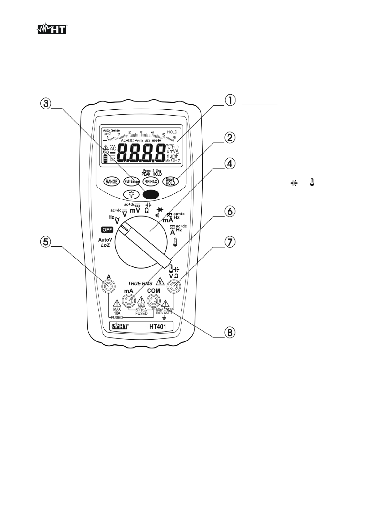
4.1.1. Description of the controls
CAPTION:
1. LCD display
2. Function keys
3. MODE key
4. Rotary switch
5. Input terminal A
6. Input terminal mA
7. Input terminal for
measuring V .
8. Input terminal COM
Fig. 1: Instrument description
EN - 6
Page 8

HT401
4.2. DESCRIPTION OF FUNCTION KEYS
The following § describes the functions of the different keys. When pressing a key, the
display shows the symbol of the activated function and the buzzer sounds.
4.2.1. RANGE key
Press the RANGE key to activate the manual mode and to disable the Autorange function.
The symbol “RANGE” appears in the upper left part of the display. In manual mode,
cyclically press the RANGE key to change measuring range: the relevant decimal point will
change position. The RANGE key is not active in the switch position / . In Autorange
mode, the instrument selects the most appropriate ratio for carrying out the measurement.
If a rdg is higher than the maximum measurable value, the indication “O.L” appears on the
display. Press and hold the RANGE key for more than 1 second to exit the manual mode
and restore the Autorange mode.
4.2.2. VoltSense key
The VoltSense key permits the detection of AC voltage without contact. Perform the
herewith steps:
1. Switch on the instrument in any position of selector
2. Approach the instrument close to the point of test
3. Press and hold the VoltSense key. If an AC voltage is detected a continuous sound is
emitted by the instrument and the number of LCD segments indicates the intensity of
electric field in the point of test. In case of no indication from the instrument a
voltage could be present
4. Release the VoltSense key to exit from the function
4.2.3. MIN MAX key
Pressing the MIN MAX key once activates the detection of maximum and minimum values
of the quantity being tested. Both values are constantly updated and are displayed
cyclically every time the same key is pressed again. The display shows the symbol
associated with the selected function: “MAX” for maximum value and “MIN” for minimum
value. The flashing symbol “MAX MIN” shows the current value on the display. The MAX
MIN key is not active when the HOLD function is activated.
Press and hold the MIN MAX key for more than 1 second or turn the selector to exit the
function.
4.2.4. SMART HOLD key
Pressing the SMART HOLD key keeps the value of the measured quantity on the dis play.
The symbol “HOLD” appears on the display, the instrument emits a continuous acoustic
alarm and the display flashes if the measured value differs by more than 50 dgt from the
value read on the display. Press the SMART HOLD key again or turn the rotary switch to
exit the function.
4.2.5. Backlight key
Press the key to activate/deactivate the backlight of the display. This function is active
in any position of the rotary switch.
4.2.6. MODE key
Press the MODE key to activate the secondary functions (orange-coloured on the switch).
Pressing the key again takes the instrument back to primary (initial) functions.
EN - 7
Page 9

HT401
4.3. INTERNAL MODES OF INSTRUMENT
4.3.1. PEAK/HOLD mode
When operating in PEAK/HOLD function, the instrument records the Max or Min voltage or
current peak values. When a new MAX peak value or MIN peak value is detected, the
instrument saves the new values. Press the key again to stop recording peak values.
Press and hold the MIN/MAX key for 2 seconds to activate the PEAK HOLD mode.
Press and hold the MIN MAX key for more than 1 second or turn the selector to exit the
function.
4.3.2. AC+DC mode
In the voltage and current measurements by pressing MODE key the selection of “AC+DC”
measurement mode is possible. This mode permits the evaluation of possible DC
components overlapped on a generic alternate waveform signal and this can be very
useful for the measurements on impulsive signals typically of non-linear loads (e.g:
welders, electric ovens, etc).
4.3.3. AutoV LoZ mode
This mode permits to perform the AC voltage measurement with a low input impedance in
way to avoid the wrong rdg due to stray voltage in capacitive coupled
CAUTION
Inserting the instrument between phase and ground conductors, the RCDs
protection devices can be tripping out during the test. In this case the
measurement can be performed only inserting the instrument between
phase and neutral conductor firstly checking the neutral electrical potential
4.3.4. Disabling the Auto Power OFF function
In order to preserve internal batteries, the instrument switches automatically off
approximately 20 minutes after it was last used. The symbol “APO” appears on the display
when this function is active. When the instrument must be used for long periods of time, it
may be useful to deactivate the Auto Power Off function as follows:
Switch off the instrument (OFF)
Switch on the instrument by turning the rotary switch and pressing and holding the
MODE key. The “AoFF” message is shown at display
Switch off and on the instrument to automatically enable the feature
4.3.5. Wrong insertion indication
A continuous sound and a “Prob” message are shown by the instrument in case of wrong
insertion of test leads according to the position of function selector. Fit the test lead in the
correct configuration in way to stop the alarm condition
EN - 8
Page 10

HT401
4.4. OPERATING INSTRUCTIONS
4.4.1. DC Voltage measurement
The maximum input DC voltage is 1000 V. Do not measure voltages
exceeding the limits given in this manual. Exceeding these limits could
result in electrical shocks to the user and damage to the instrument.
CAUTION
Fig. 2: DC voltage measurement
1. Select
or positions
2. Press the MODE key to activate “DC” or “AC+ DC” modes (see § 4.3.2)
3. Press the RANGE key to activate manual range selection (see § 4.2.1) or use the
Autorange feature. If the voltage value is unknown select the maximum range
4. Insert the red cable into input lead
V and the black cable into input lead COM
5. Position the red lead and the black lead respectively in the points with positive and
negative potential of the circuit to be measured (see Fig. 2). The voltage value is
shown on the display
6. The message “O.L” indicates that the voltage being measured exceeds the maximum
value measurable by the instrument
7. When symbol “-” appears on the instrument’s display, it means that voltage has the
opposite direction with respect to the connection in Fig. 2
8. For Maximum and Minimum value measurement and HOLD function measurement,
please refer to § 4.2
EN - 9
Page 11

HT401
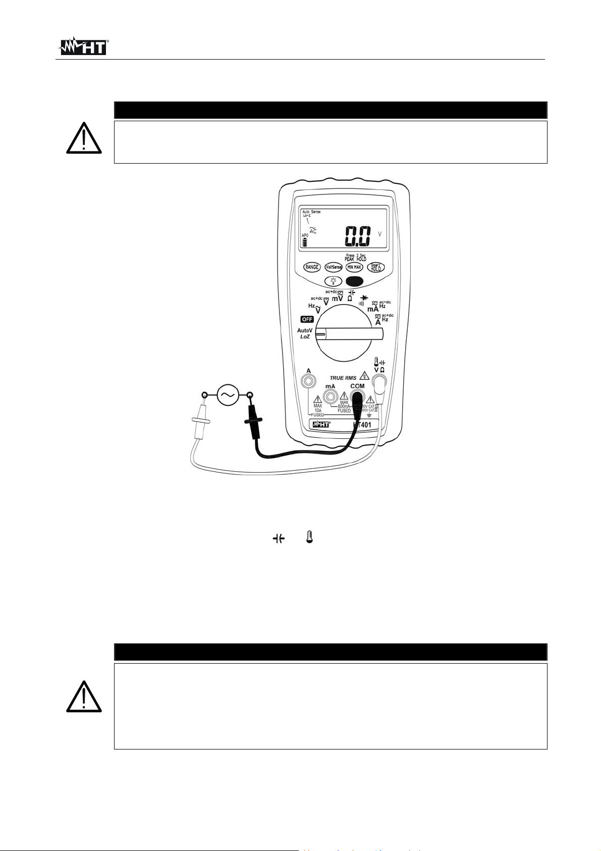
4.4.2. AC Voltage measu rement and Frequency
CAUTION
The maximum input AC voltage is 1000 V. Do not measure voltages
exceeding the limits given in this manual. Exceeding these limits could
result in electrical shocks to the user and damage to the instrument.
Fig. 3: AC voltage measurement
1. Select the
or position
2. Press the MODE key to activate “AC” or “AC+ DC” modes (see § 4.3.2)
3. Press the RANGE key to activate manual range selection (see § 4.2.1) or use the
Autorange feature. If the voltage value is unknown select the maximum range
4. Insert the red cable into input lead V and the black cable into input lead COM
(see Fig. 3)
5. Position the test leads in the desired points of the circui t to be measured. The voltage
value is shown on the display
6. The message “O.L” indicates that the voltage being measured exceeds the maximum
value measurable by the instrument
7. Press the MODE key to activate Hz frequency measurement (only
position). The
“Hz” symbol is shown at display. Bargraph is disabled for this measurement
8. For Maximum and Minimum value measurement, HOLD function and PEAK HOLD
measurement, please refer to § 4.2
EN - 10
Page 12
HT401
4.4.3. AC Voltage measurement with low input impedance
CAUTION
The maximum input AC voltage is 1000 V. Do not measure voltages
exceeding the limits given in this manual. Exceeding these limits could
result in electrical shocks to the user and damage to the instrument.
Fig. 4: AC voltage with low impedance (LoZ)
1. Select the AutoV LoZ position (see § 4.3.3)
2. Insert the red cable into input lead V and the black cable into input lead COM
(see Fig. 4)
3. Position the test leads in the desired points of the circui t to be measured. The voltage
value is shown on the display
4. The message “O.L” indicates that the voltage being measured exceeds the maximum
value measurable by the instrument
5. For HOLD function please refer to § 4.2
CAUTION
Inserting the instrument between phase and ground conductors, the RCDs
protection devices can be tripping out during the test. In this case the
measurement can be performed only inserting the instrument between
phase and neutral conductor firstly checking the neutral electrical potential
Wait about 1 hours to perform resistance/continuity test measurements
after the AutoV test
EN - 11
Page 13
HT401
4.4.4. DC Current measurement
The maximum input DC current is 10A. Do not measure currents exceeding
the limits given in this manual. Exceeding these limits could result in
electrical shocks to the user and damage to the instrument
CAUTION
Fig. 5: DC current measurement
1. Cut off power supply from the circuit to be measured.
2. Select the
or positions
3. Insert the red cable and the black cable into the input terminals mA or A and COM
4. Press the MODE key to activate “DC” or “AC+ DC” modes (see § 4.3.2)
5. Press the RANGE key to activate manual range selection (see § 4.2.1) or use the
Autorange feature. If the current value is unknown select the maximum range
6. Connect the red lead and the black lead in series to the circuit whose current you want
to measure, respecting polarity and the current direction indicated in Fig. 5
7. Supply the circuit to be measured. The display shows the value of current.
8. The message “O.L” indicates that the current being measured exceeds the maximum
value measurable by the instrument
9. When symbol “-” appears on the instrument’s display, it means that current has the
opposite direction with respect to the connection in Fig. 5
10. For Maximum and Minimum value measurement and HOLD function measurement,
please refer to § 4.2
EN - 12
Page 14

HT401
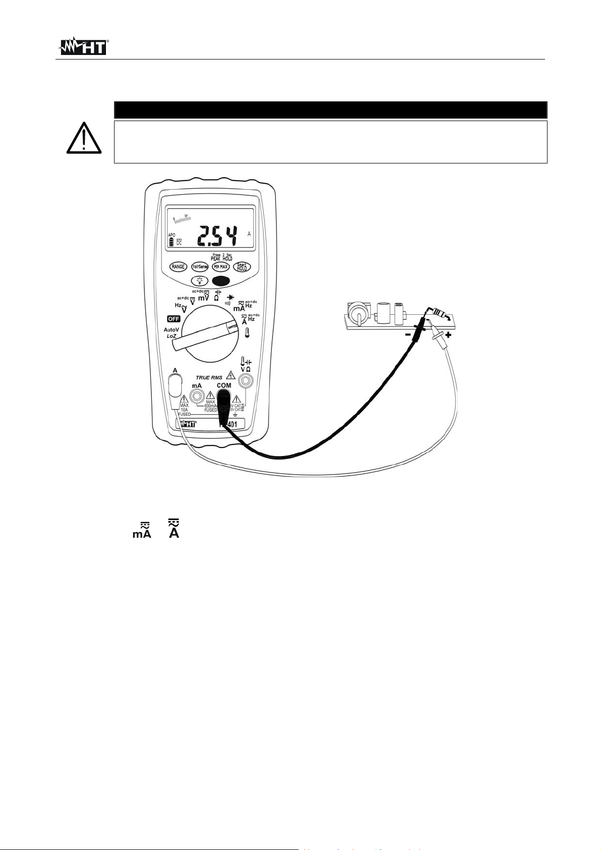
4.4.5. AC Current measurement and Frequency
CAUTION
The maximum input AC current is 10A. Do not measure currents exceeding
the limits given in this manual. Exceeding these limits could result in
electrical shocks to the user and damage to the instrument.
Fig. 6: AC current measurements
1. Cut off power supply from the circuit to be measured.
2. Select the or positions
3. Insert the red cable and the black cable into the input terminals mA or A and COM
4. Press the MODE key to activate “AC” or “AC+ DC” modes (see § 4.3.2)
5. Press the RANGE key to activate manual range selection (see § 4.2.1) or use the
Autorange feature. If the current value is unknown select the maximum range
6. Connect the red lead and the black lead in series to the circuit whose current you want
to measure, respecting polarity and the current direction indicated in Fig. 6
7. Supply the circuit to be measured. The display shows the value of current.
8. The message “O.L” indicates that the current being measured exceeds the maximum
value measurable by the instrument
9. Press the MODE key to activate Hz frequency measurement (only position). The
“Hz” symbol is shown at display. Bargraph is disabled for this measurement
10. For Maximum and Minimum value measurement, HOLD function and PEAK HOLD
measurement, please refer to § 4.2
EN - 13
Page 15
HT401
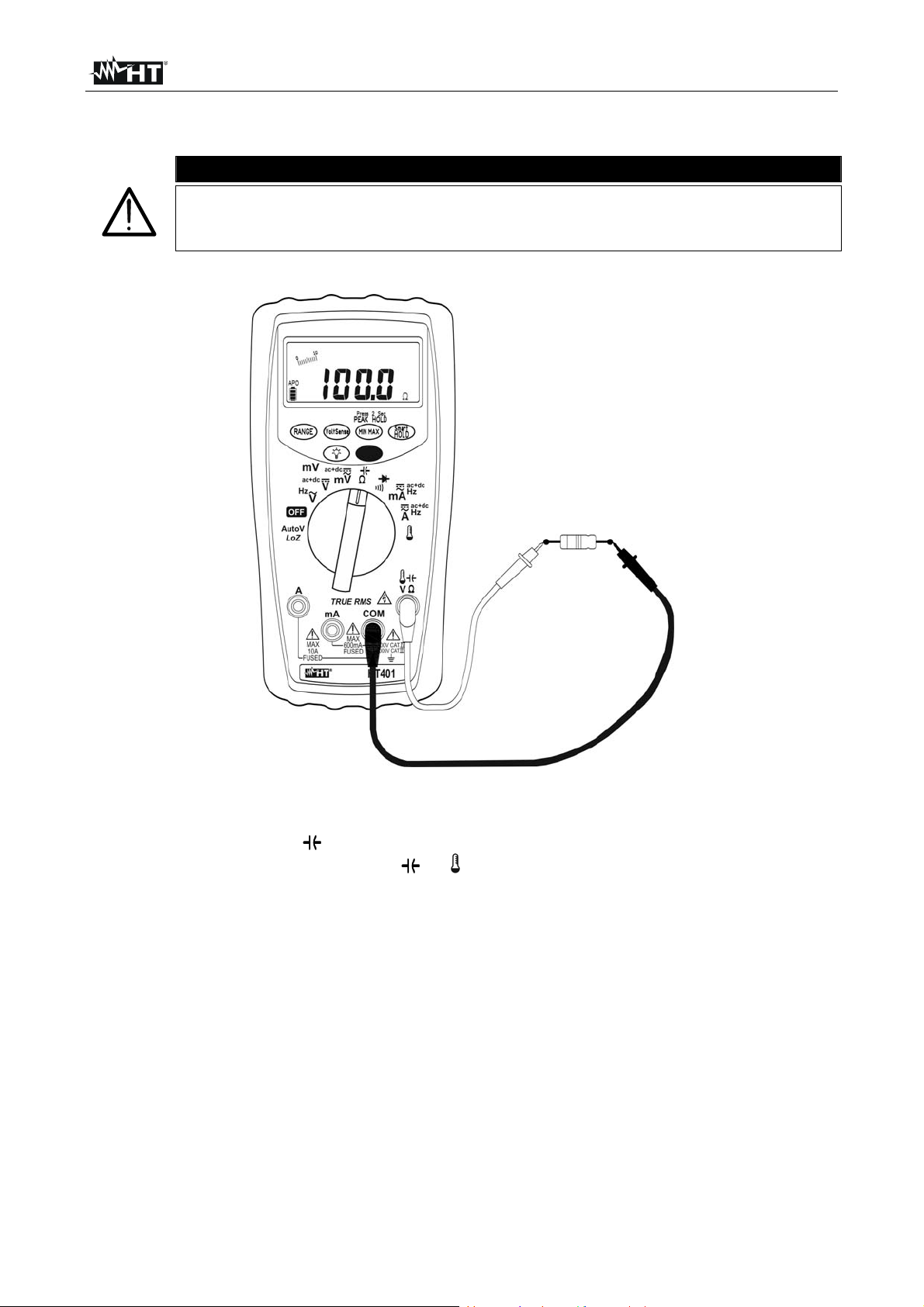
4.4.6. Resistance measurement
Before attempting any resistance measurement, cut off power supply from
the circuit to be measured and make sure that all capacitors are discharged,
if present.
CAUTION
Fig. 7: Resistance measurement
1. Select the position /
2. Insert the red cable into input lead V and the black cable into input lead COM
3. Press the RANGE key to activate manual range selection (see § 4.2.1) or use the
Autorange feature. If the resistance value is unknown select the maximum range
4. Position the test leads in the desired points of the circuit to be measured. The value of
resistance is shown on the display (see Fig. 7)
5. The message “O.L” indicates that the resistance being measured exceeds the
maximum value measurable by the instrument.
6. For Maximum and Minimum value measurement and HOLD function please refer to §
4.2
EN - 14
Page 16
HT401
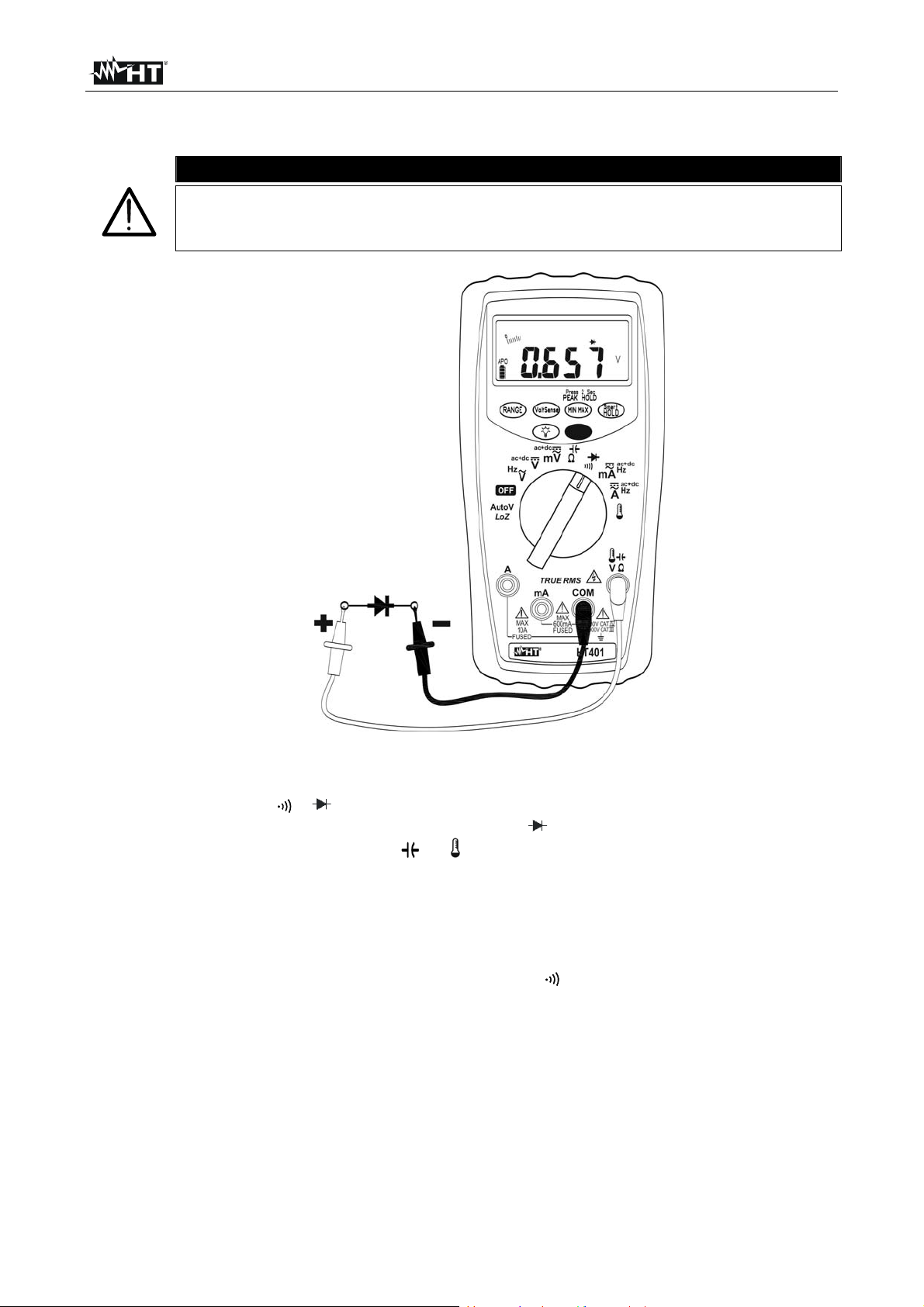
4.4.7. Diode and Continuit y test
Before attempting any resistance measurement, cut off power supply from
the circuit to be measured and make sure that all capacitors are discharged,
if present.
CAUTION
Fig. 8: Diode and continuity test
1. Select the position /
2. Press the MODE key to start testing diodes. The “ ” symbol is shown at display
3. Insert the red cable into input lead V and the black cable into input lead COM
4. Connect the red lead to the anode and the black lead to t he cathode of the diode (see
Fig. 8). The instrument’s display shows the direct polarization voltage. This voltage is
typically 0.4 ~ 0.9V with good junctions.
5. Reverse connections and measure potential drop at the ends of the diode. An “O.L”
result on the display indicates the correct operation of the junction.
6. Press the MODE key to select Continuity test. The “ ” symbol is shown at display
7. Insert the red and black cables as described in “Resistance measurement” to carry out
the measurement. The buzzer is ON for resistance values < 30
8. For HOLD function please refer to § 4.2
EN - 15
Page 17
HT401
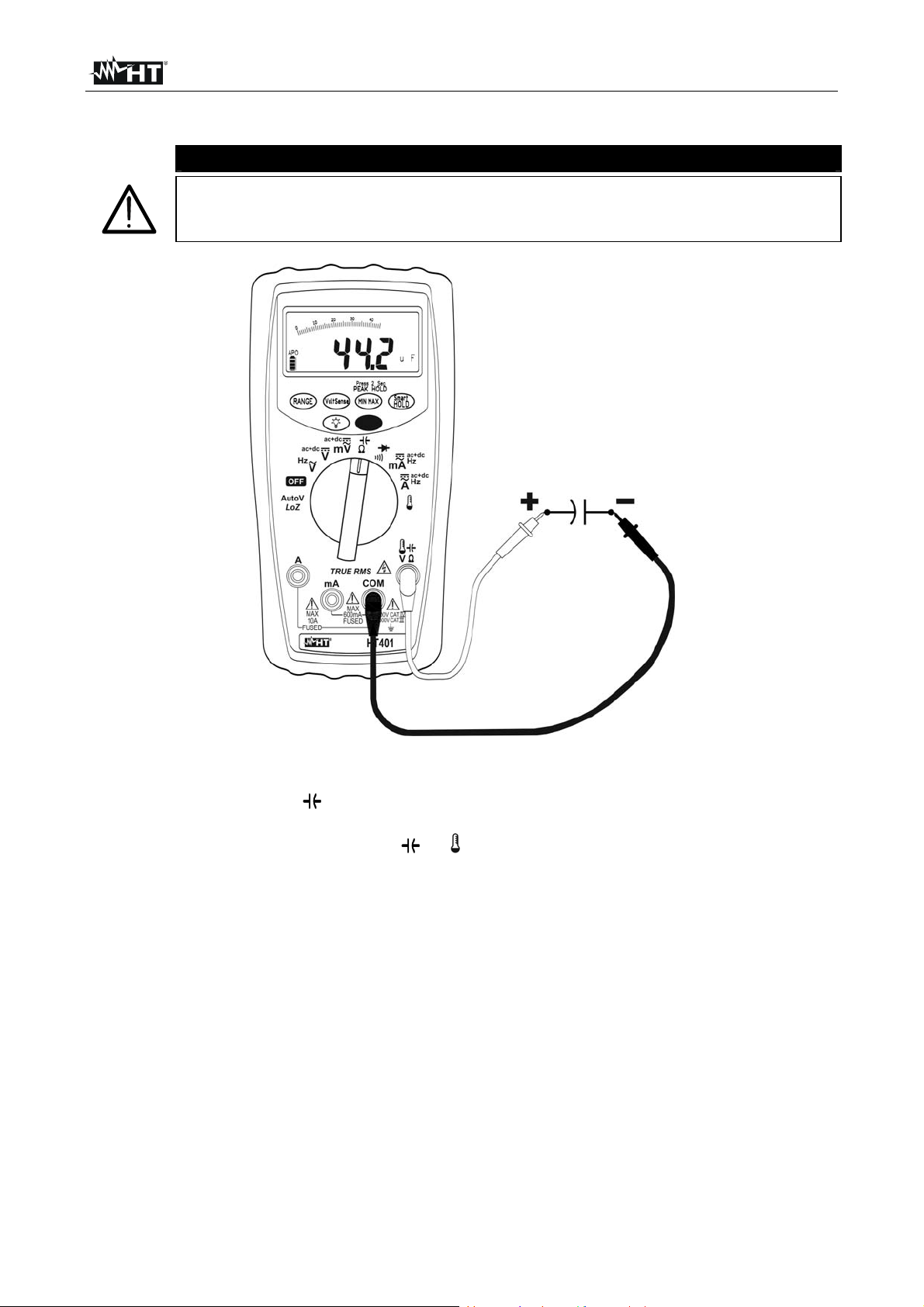
4.4.8. Capacitance measurement
Before carrying out capacitance measurements on circuits or capacitors, cut
off power supply from the circuit being tested and let all capacitance in it be
discharged
CAUTION
Fig. 9: Capacitance measurement
1. Select the position /
2. Press MODE key to activate capacitance measurement
3. Insert the red cable into input lead
V and the black cable into input lead COM
4. Press the RANGE key to activate manual range selection (see § 4.2.1) or use the
Autorange feature. If the capacitance value is unknown select the maximum range
5. Position the leads at the ends of the capacitor to be tested, respecting the indicated
polarity. The value of capacitance is shown on the display with automatic range
selection
6. The message “O.L” indicates that the capacitance being measured exceeds the
maximum value measurable by the instrument.
7. For Maximum and Minimum value measurement and HOLD function please refer to §
4.2
EN - 16
Page 18

HT401
4.4.9. Temperature measurement
Fig. 10: Temperature measurement
1. Select the position
2. Press the MODE key to select measurement in °C or °F
3. Insert the supplied adapter into the input terminals V and COM respecting the red
and black colours found on it.
4. Connect the K-type probe to the instrument by means of the adapter, respecting the
positive and negative polarity on the probe’s plug. The display shows the value of
temperature
5. The message “O.L” indicates that the temperature being measured exceeds the
maximum value measurable by the instrument
6. For Maximum and Minimum value measurement and HOLD function please refer to §
4.2
EN - 17
Page 19

HT401
5. MAINTENANCE
CAUTION
Only expert and trained technicians should perform maintenance
operations. Before carrying out this operations, make sure you have
disconnected all cables from the input terminals
Do not use the instrument in environments with high humidity levels or
high temperatures. Do not expose to direct sunlight
Always switch off the instrument after use. In case the instrument is not to
be used for a long time, remove the battery to avoid liquid leaks that could
damage the instrument’s internal circuits
5.1. BATTERY AND FUSES REPLACEMENT
When the LCD displays the flashing symbol “ ”, it is necessary to replace the battery.
Fig. 11: Replacement of the battery and internal fuses
Replacing battery
1. Position the rotary switch to OFF and remove the cables from the input terminals.
2. Remove the protection shell from the instrument
3. Loosen the screw of the rear battery compartment cover, remove the cover and extract
the battery (see Fig. 11)
4. Insert a new battery of the same type (see § 6.1.3) respecting the indicated polarity,
close the compartment and reinsert the protection shell
Replace fuses
1. Position the rotary switch to OFF and remove the cables from the input terminals
2. Remove the protection shell from the instrument
3. Loosen the screw of the rear battery compartment cover and the four fastening screws
of the rear semi-shell
4. Remove the damaged fuse and insert a new fuse of the same type (see § 6.1.3).
Close the semi-shell and reinsert the protection shell
5.2. CLEANING THE INSTRUMENT
Use a soft and dry cloth to clean the instrument. Never use wet cloths, solvents, water, etc.
5.3. END OF LIFE
CAUTION: the symbol on the instrument indicates that the appliance and its
accessories must be collected separately and correctly disposed of.
EN - 18
Page 20
HT401
6. TECHNICAL SPECIFICATIONS
6.1. TECHNICAL CHARACTERISTICS
Accuracy is indicated as [% rdg + (dgt number) * resolution] at 23°C ± 5°C,< 80%HR
DC Voltage
Range Resolution Accuracy Input impedance
60.00mV 0.01mV
(0.08rdg+10dgt)
600.0mV 0.1mV
6.000V 0.001V
60.00V 0.01V
(0.08rdg+2dgt)
10M // < 100pF
600.0V 0.1V
1000V 1V
AC TRMS Voltage
Range Resolution
60.00mV 0.01mV
600.0mV 0.1mV
6.000V 0.001V
60.00V 0.01V
600.0V 0.1V
1000V 1V
For non-sinusoidal voltages, add the following errors depending on the crest factor (CF):
1.4 < CF < 2.0 1%rdg to the accuracy
2.0 < CF < 2.5 2.5%rdg to the accuracy
2.5 < CF < 3.0 4.0%rdg to the accuracy
Max crest factor: 3.0 (0 ÷ 3000dgt); 2.0 (3000 ÷ 5000dgt); 1.6 (5000 ÷ 6000dgt)
PEAK HOLD feature: specified accuracy ±150dgt
Accuracy
(50Hz 1kHz)
(1.2rdg+5dgt)
(0.8rdg+5dgt)
Input impedance
10M // < 100pF
AC + DC TRMS Voltage
Range Resolution
60.00mV 0.01mV
600.0mV 0.1mV
6.000V 0.001V
60.00V 0.01V
600.0V 0.1V
1000V 1V
For non-sinusoidal signals, add the same errors as AC TRMS voltage
PEAK HOLD feature: specified accuracy ±150dgt
Accuracy
(50Hz 1kHz)
(2.0rdg+10dgt)
(2.0rdg+5dgt)
Input impedance
10M // < 100pF
Auto-V (low impedance AC/DC voltage measurement)
Range Resolution Accuracy Input impedance
600.0VDC 0.1V
1000VDC 1V
600.0VAC 0.1V
1000VAC 1V
For non-sinusoidal signals, add the same errors as AC TRMS voltage
PEAK HOLD feature: specified accuracy ±150dgt
(0.8rdg+3dgt) about 3k
Protection against
overcharge
1000VDC/ACrms
Protection against
overcharge
1000VDC/ACrms
Protection against
overcharge
1000VDC/ACrms
Protection against
overcharge
1000VDC/ACrms
EN - 19
Page 21

HT401
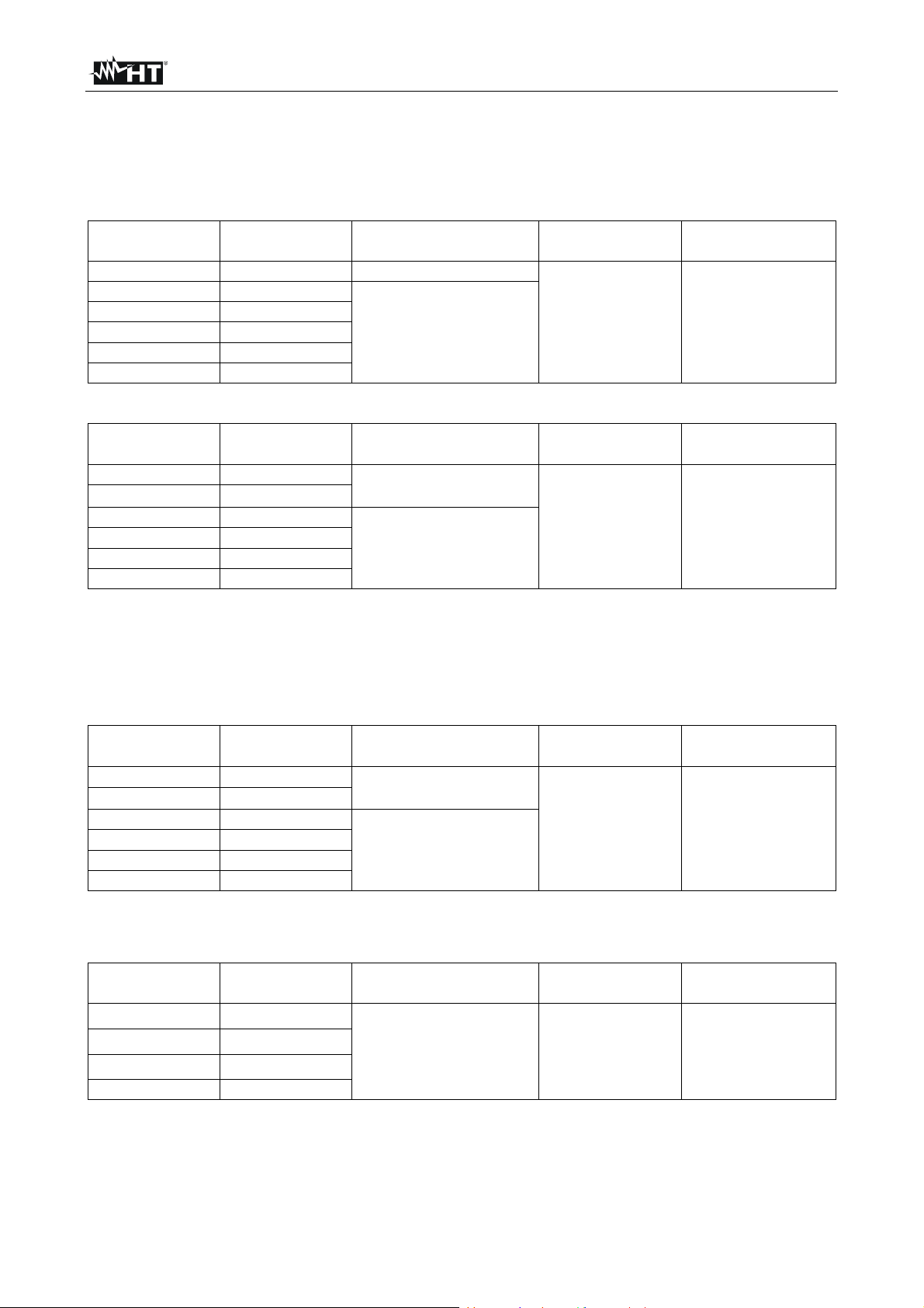
DC Current
Range Resolution Accuracy Measuring time
60.00mA 0.01mA
600.0mA 0.1mA
6.000A 0.001A
(0.8rdg+3dgt)
3min (A)
10min (mA)
10.00A 0.01A
Protection against
overcharge
max 440mA (mA)
max 11A (A)
AC TRMS Current
Range Resolution
Accuracy
(50Hz 1kHz)
60.00mA 0.01mA
600.0mA 0.1mA
(1.2rdg+3dgt)
6.000A 0.001A
10.00A 0.01A
For non-sinusoidal currents, add the same errors as AC TRMS voltage
PEAK HOLD feature: specified accuracy ±150dgt
Measuring time
3min (A)
10min (mA)
Protection against
overcharge
max 440mA (mA)
max 11A (A)
AC + DC TRMS Current
Range Resolution
Accuracy
(50Hz 1kHz)
60.00mA 0.01mA
600.0mA 0.1mA
(2.0rdg+5dgt)
6.000A 0.001A
10.00A 0.01A
For non-sinusoidal signals, add the same errors as AC TRMS voltage
PEAK HOLD feature: specified accuracy ±150dgt
Measuring time
3min (A)
10min (mA)
Protection against
overcharge
max 440mA (mA)
max 11A (A)
Frequency
Range Resolution Accuracy
Minimum
frequency
100.00Hz 0.01Hz
1000.0Hz 0.1Hz
10.000kHz 0.001kHz
(0.1rdg+2dgt)
1Hz 1000VDC/ACrms
100.00KHz 0.01KHz
Sensitivity: > > 5.0Vpp (VAC 1Hz ~ 10kHz); > 10Vpp ( VAC 10kHz ~ 100kHz); > 2mApp (ACmA); > 0.2App (ACA)
Protection against
overcharge
Resistance
Range Resolution Accuracy (*)
600.0 0.1 (0.8rdg+5dgt)
6.000k 0.001k
60.00k 0.01k
600.0k 0.1k
(0.8rdg+2dgt)
6.000M 0.001M
Maximum open
circuit voltage
2.5V
(600 and 6k)
0.6V
(other ranges)
40.00M (*) 0.01M (1.0rdg+5dgt)
Test current : approx. 0.1mA
(*) Specified for measurements 1 hour after Auto-V test. Add 10dgt for measurements before this interval
(**) Small instability < ± 50dgt for measurements >10 M
Protection against
overcharge
1000VDC/ACrms
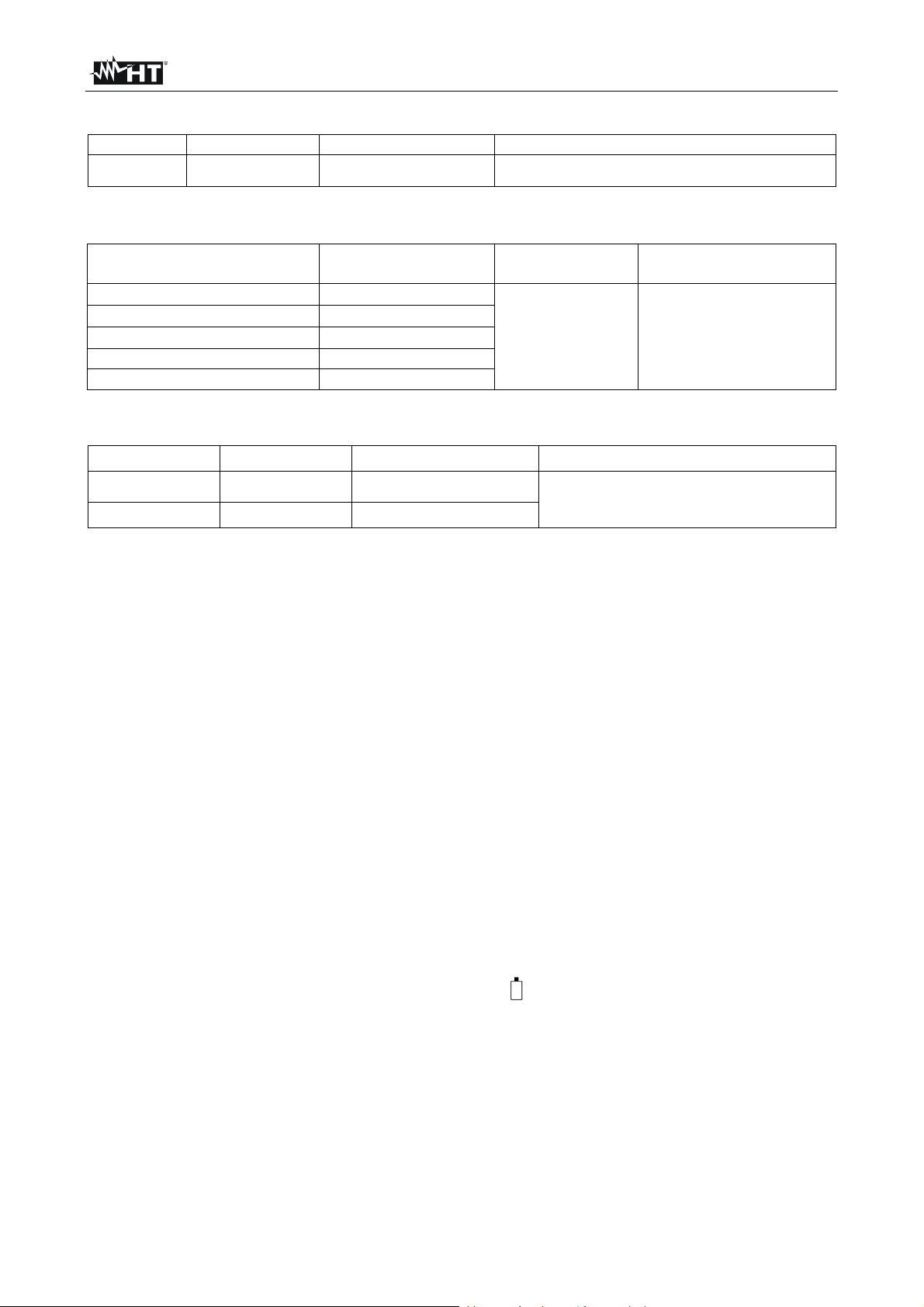
Diode test
Open
circuit
voltage
Protection against
overcharge
Range Resolution Accuracy
2.000V 1mV
(1.5rdg+2dgt)
current
< 0.4mA <2.5V 1000VDC/ACrms
Test
EN - 20
Page 22
HT401
Continuity test
Range Resolution Accuracy Protection against overcharge
600 0.1 (0.8rdg+5dgt)
Buzzer activated for R < 30 and deactivated for R > 100
1000VDC/ACrms
Capacity
Range Resolution Accuracy
1.000F 0.001F
10.00F 0.01F
100.0F 0.1F
1.000mF 0.001mF
10.00mF 0.01mF
Maximum time for reaching results: 0.7s C<1mF; 3s C> 1 mF
(1.2rdg+2dgt)
Protection against
overcharge
1000VDC/ACrms
Temperature with type K probe
Range Resolution Accuracy (*) Protection against overcharge
-40.0 400 °C
-40.0 752 °F
(*) The specified accuracy applies at the reference environmental temperature ±1°C. If temper ature differs by more than
5 degrees, to obtain the declared accuracy, a stabilization time of 2 hours is required
0.1°C
0.1°F
(1.0rdg+10dgt)
(1.0rdg+18dgt)
1000VDC/ACrms
6.1.1. Electrical characteristics
Conversion: TRMS
Sampling frequency: 3 times per second
Temperature coefficient: 0.15x(accuracy) /°C, <18°C or >28°C
6.1.2. Reference standards
The instrument complies with standards: IEC/EN 61010-1, UL61010-1,
Insulation: double insulation
Pollution level: 2
Overvoltage category: CAT IV 600V, CAT III 1000V
Max height of use: 2000m (6561ft)
6.1.3. General characteristics
Mechanical characteristics
Size (with shell): 190(L) x 94(W) x 48 (H) mm (7.5 x 3.7x 1.9 in)
Weight (battery included): 460g (1Lv)
Power supply
Battery type: 1x9V battery NEDA1604, JIS006P, IEC6F22
Low battery indication: symbol “ ” at display
Battery duration: approx. 150 hours (no backlight)
Auto Power OFF: after 20 minutes of idleness
Fuses: FUSE71: F11A/1000V, 20kA
FUSE72: F440mA/1000V, 10kA
Display
Characteristics: 4 LCD, 6000 dots plus decimal sign, bargraph
and backlight
Over range indication: “O.L” or “-O.L”
EN - 21
Page 23

HT401
6.2. ENVIRONMENT
6.2.1. Environmental conditions for use
Reference temperature: 23 ± 5°C (73 ± 41°F)
Operating temperature/humidity: -10 ÷ 50°C (14 ÷ 122°F)
-10 ÷ 30°C (<80%RH); 30 ÷ 40°C (<75%RH);
40 ÷ 50°C (<45%RH)
Storage temperature/humidity: -20 ÷ 60°C (-4 ÷ 140°F) (battery not inserted)
Storage humidity: <80%RH (battery not inserted)
This instrument satisfies the requirements of Low Voltage Directive 2006/95/EC
(LVD) and of EMC Directive 2004/108/EC
6.3. ACCESSORIES
6.3.1. Standard accessories
Couple of test leads
K probe adapter and wire probe
Protection holster
Battery (not inserted)
User manual
6.3.2. Optional accessories
Couple of test leads Cod. 4413-2
K-type probe for air and gas temperature Cod. TK107
K-type probe for semisolid substance temperature Cod. TK108
K-type probe for liquid substance temperature Cod. TK109
K-type probe for surface temperature Cod. TK110
K-type probe for surface temperature with 90° tip Cod. TK111
EN - 22
Page 24

HT401
7. SERVICE
7.1. WARRANTY CONDITIONS
This instrument is warranted against any material or manufacturing defect, in compliance
with the general sales conditions. During the warranty period, defective parts may be
replaced. However, the manufacturer reserves the right to repair or replace the product.
Should the instrument be returned to the After-sales Service or to a Dealer, transport will
be at the Customer’s charge. However, shipment will be agreed in advance.
A report will always be enclosed to a shipment, stating the reasons for the product’s return.
Only use original packaging for shipment; any damage due to the use of non-original
packaging material will be charged to the Customer.
The manufacturer declines any responsibility for injury to people or damage to property.
The warranty shall not apply in the following cases:
Repair and/or replacement of accessories and battery (not covered by warranty).
Repairs that may become necessary as a consequence of an incorrect use of the
instrument or due to its use together with non-compatible appliances.
Repairs that may become necessary as a consequence of improper packaging.
Repairs which may become necessary as a consequence of interventions performed
by unauthorized personnel.
Modifications to the instrument performed without the manufacturer’s explicit
authorization.
Use not provided for in the instrument’s specifications or in the instruction manual.
The content of this manual cannot be reproduced in any form without the manufacturer’s
authorization.
Our products are patented and our trademarks are registered. The manufacturer
reserves the right to make changes in the specifications and prices if this is due to
improvements in technology.
7.2. SERVICE
If the instrument does not operate properly, before contacting the After-sales Service,
please check the conditions of battery and cables and replace them, if necessary.
Should the instrument still operate improperly, check that the product is operated
according to the instructions given in this manual.
Should the instrument be returned to the After-sales Service or to a Dealer, transport will
be at the Customer’s charge. However, shipment will be agreed in advance.
A report will always be enclosed to a shipment, stating the reasons for the product’s return.
Only use original packaging for shipment; any damage due to the use of non-original
packaging material will be charged to the Customer.
EN - 23
 Loading...