

Page 1
User manual
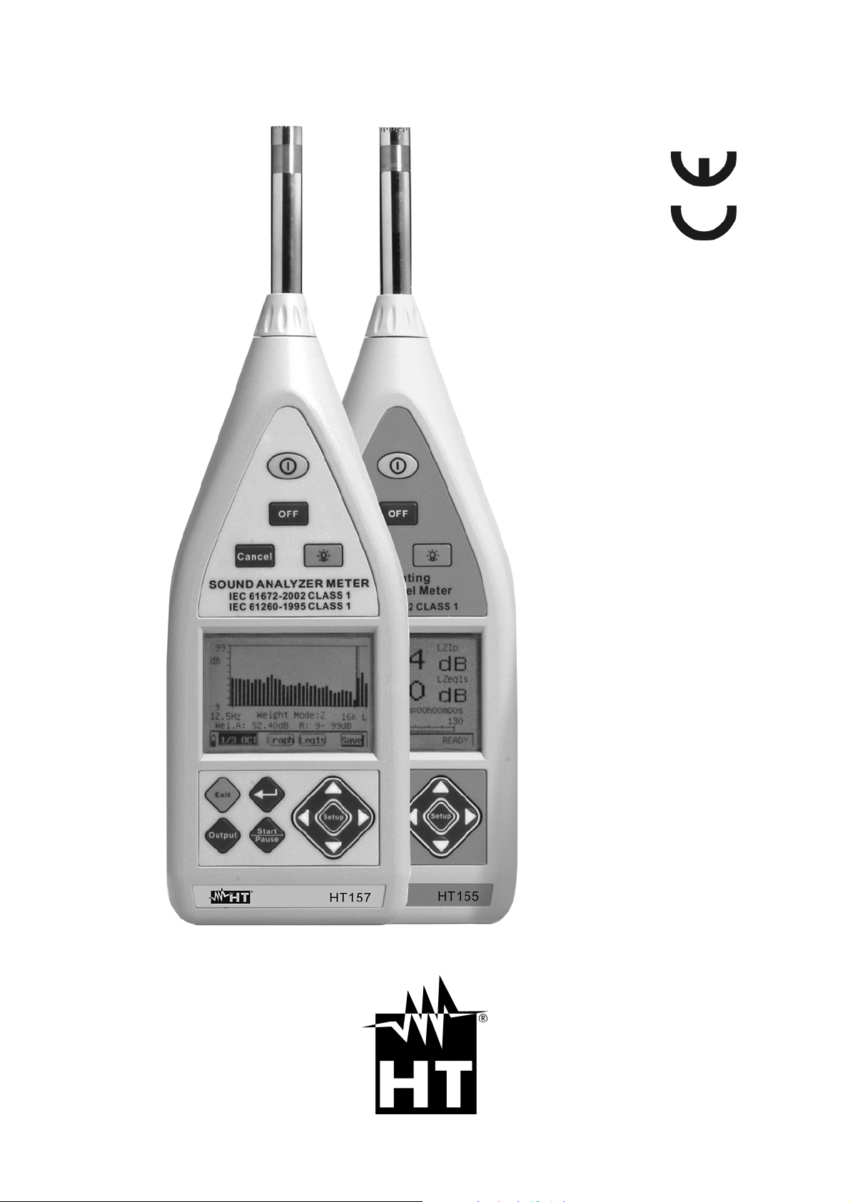
HT155 – HT157
Copyright HT ITALIA 2011 Release EN 1.02 - 28/12/2011
Page 2

Page 3

HT155 - HT157
Table of contents:
1. PRECAUTIONS AND SAFETY MEASURES .................................................................. 3
1.1. Preliminary instructions .................................................................................................... 3
1.2. During use ........................................................................................................................ 3
1.3. After use ........................................................................................................................... 3
2. GENERAL DESCRIPTION .............................................................................................. 4
3. PREPARATION FOR USE .............................................................................................. 5
3.1. Initial inspections .............................................................................................................. 5
3.2. Instrument power supply .................................................................................................. 5
3.3. Calibration ........................................................................................................................ 5
3.4. Storage ............................................................................................................................. 5
4. OPERATING INSTRUCTIONS ........................................................................................ 6
4.1. Instrument description ...................................................................................................... 6
4.1.1. Front panel .................................................................................................................... 6
4.1.2. Output interface ............................................................................................................. 6
4.2. Description of function keys ............................................................................................. 7
4.3. Analogue output description............................................................................................. 7
4.4. Display contrast adjustment ............................................................................................. 8
4.5. Turning ON/OFF the instrument ...................................................................................... 8
4.6. Configuration of measuring parameters ........................................................................... 9
4.6.1. Foreword ....................................................................................................................... 9
4.6.2. Programming menu interface ........................................................................................ 9
4.6.3. Defining the measure name ........................................................................................ 11
5. CARRYING OUT MEASUREMENTS ............................................................................ 13
5.1. Statistic analysis of noise ............................................................................................... 13
5.1.1. Initial operations .......................................................................................................... 13
5.1.2. Statistic analysis operations ........................................................................................ 14
5.1.3. 24-hour analysis operations ........................................................................................ 17
5.1.4. Integration analysis operations .................................................................................... 21
5.2. Noise analysis in 1/1 and 1/3 octave band (HT157 only)............................................... 24
5.2.1. Initial operations .......................................................................................................... 24
5.2.2. Octave band analysis (1/1) .......................................................................................... 25
5.2.2.1. Operations for sections LIST, GRAPH and TOTAL ................................................... 25
5.2.3. Analysis in third-octave band (1/3) .............................................................................. 30
5.2.3.1. Operations for sections LIST, GRAPH ....................................................................... 30
5.2.3.2. Operations in TOTAL section ..................................................................................... 33
6. INSTRUMENT ACOUSTIC CALIBRATION ................................................................... 35
6.1.1. Foreword ..................................................................................................................... 35
6.1.2. Preliminary operations ................................................................................................. 35
6.1.3. Acoustic calibration with calibrator HT151 .................................................................. 37
6.1.3.1. Replacing the calibrator battery ................................................................................. 38
6.1.3.2. Calibration result display ............................................................................................ 39
6.1.4. Direct acoustic Calibration ........................................................................................... 39
7. OPERATIONS WITH THE MEMORY ............................................................................ 40
7.1. Recalling results on the display...................................................................................... 40
7.1.1. Recalling the statistic analysis data on the display ..................................................... 41
7.1.2. Recalling the 24H analysis data on the display ........................................................... 42
7.1.3. Recalling the integration measurement data on the display ........................................ 44
7.1.4. Recalling the data of the octave band analysis (1/1) on the display ........................... 45
7.1.4.1. Recalling the data of the analysis in Total octave band (1/1) ..................................... 46
7.1.5. Recalling the data of the analysis in third-octave band (1/3) on the display ............... 47
7.2. Data transfer onto USB Pen Drive ................................................................................. 48
8. OPERATIONS WITH SOUNDVIEW SOFTWARE ......................................................... 49
EN - 1
Page 4

HT155 - HT157
8.1. Foreword ........................................................................................................................ 49
8.2. Minimum system requirements ...................................................................................... 49
8.3. Installing the driver USB ................................................................................................. 49
8.4. Use of SoundView software ........................................................................................... 51
8.4.1. Copy and Print commands .......................................................................................... 51
8.4.2. File menu ..................................................................................................................... 52
8.4.3. View menu ................................................................................................................... 53
8.4.4. Name Menu ................................................................................................................. 53
8.4.5. Result menu ................................................................................................................ 54
8.4.6. Calibration menu ......................................................................................................... 54
8.4.7. Help menu ................................................................................................................... 54
9. MAINTENANCE ............................................................................................................ 55
9.1. General information ........................................................................................................ 55
9.2. replacing the batteries .................................................................................................... 55
9.3. Cleaning the instrument ................................................................................................. 55
9.4. End of life ....................................................................................................................... 55
10. TECHNICAL SPECIFICATIONS ............................................................................. 56
10.1. Technical specifications .......................................................................................... 56
10.2. Statistic analisys chararcteristics ............................................................................ 57
10.3. Characteristics of analysis in 1/1 and 1/3 octave band (HT157 only) .................... 57
10.4. Characteritics of portable calibrator HT151 ............................................................ 57
10.5. General characteristics ........................................................................................... 58
10.6. Accessories ............................................................................................................ 58
11. SERVICE ................................................................................................................ 59
11.1. Warranty conditions ................................................................................................ 59
11.2. Service .................................................................................................................... 59
12. APPENDIXES ......................................................................................................... 60
12.1. Appendix 1 – Frequency weighting characteristics ................................................ 60
12.2. Appendix 2 – characteristics of 1/3 octave band filter ............................................ 61
12.3. Appendix 3 – frequency weighting A, C ................................................................. 64
12.4. Appendix 4 – characteristics of 4Hz high-pass digital filter .................................... 65
EN - 2
Page 5
HT155 - HT157
A
1. PRECAUTIONS AND SAFETY MEASURES
The instrument has been designed in compliance with the directives regarding electronic
measuring instruments. For your safety and to prevent damaging the instrument, we
recommend following the procedures described in this manual and carefully reading all
notes preceded by the symbol .
Before and during measurements, carefully observe the following instructions:
Do not perform any measurement in humid environments.
Do not perform any measurement in the presence of gas, explosive or flammable
material, or in dusty areas.
Do not perform any measurement when anomalies are found in the instrument, such as
deformations, breaks, substance leaks, no display view, etc.
In this manual and on the instrument, the following symbols are used:
Warning: observe the instructions reported in the manual. An improper use could
damage the instrument or its components.
Instrument complying with the standards relevant to the EC mark
1.1. PRELIMINARY INSTRUCTIONS
CAUTION
The instrument has been designed for measuring sound pressure levels
(SPL) from 25dB to 140dB with frequency ranging from 10Hz to 20kHz
We recommend following the usual safety rules to protect the instrument
against improper use
After a long storage period or if the instrument has been used under critical
conditions, recalibrating the instrument is recommended (see § 6)
Check if the batteries are correctly inserted
1.2. DURING USE
We recommend carefully reading the following recommendations and instructions:
CAUTION
Failure to observe the warnings and/or instructions may damage the
instrument and/or its components or generate a danger for the operator.
Do not perform measurements in environmental conditions not within the
limit values indicated in § 10.5
lways use the windproof protection when carrying out measurements in
environments where air currents are present
Do not subject the instrument to strong mechanical stress and keep the
microphone dry
1.3. AFTER USE
When measurements are completed, turn off the instrument.
If the instrument is not to be used for a long time, remove the battery.
EN - 3
Page 6

HT155 - HT157
2. GENERAL DESCRIPTION
This manual refers to models HT155 and HT157. In the manual, the generic term
“instrument” refers to both devices and, if not otherwise indicated, characteristics are to be
considered as common to both models
The instrument has the following functions:
Measurement of sound pressure level (SPL) Type 1
Real-time and statistic analysis
Octave band and in 1/3 octave band analysis (HT157 only)
Measures weighted in frequency by means of A, C and Z curves and F, S impulses
Fast, Slow, Impulse, PeakC+, Peak C- integrations
Measurement of noise equivalent levels (Leq)
Inner memory for saving measures and recordings
AC analogue output for connection to external dataloggers
USB interface for connection to PC and/or USB pen drive
Wide backlit LCD display
The front panel of the instrument bears the function keys for the selection of the abovelisted functions (see chapter 4.2). The measured value appears on the wide LCD display
with the indication of the measuring unit and of the enabled functions.
In the lower part of the instrument there are the terminals for the AC analogue output with
3,5 mm coaxial connector and the (USB) ports for the connection of a possible DC 5V
external adapter for power supply without using the internal battery and RS-232 (nonactive output)
In the rear part of the instrument there is a hole for installing the instrument onto a possible
tripod while measuring.
EN - 4
Page 7

HT155 - HT157
3. PREPARATION FOR USE
3.1. INITIAL INSPECTIONS
Before shipment, the instrument’s electronics and mechanics have been inspected.
All possible precautions have been taken in order for the instrument to be delivered
without damage.
However, we recommend generally inspecting the instrument in order to detect any
damage suffered during transport. Should you detect any anomalies, immediately contact
the forwarding agent.
Moreover, we recommend checking that the package contains all parts listed in § 10.6.
Should you find any discrepancy, please contact the dealer.
Should it become necessary to return the instrument, please follow the instructions
reported in § 11.
3.2. INSTRUMENT POWER SUPPLY
The instrument is supplied by 4x1.5V alkaline batteries type AA IEC LR06 included in the
package. The battery duration is of approximately 8 hours. When batteries are almost flat,
the symbol “ ” appears on the display, further to the indication “BATTERY LOW”. To
replace the batteries, follow the instructions given in § 9.2.
The instrument may be supplied also by means of the provided external DC 5V supply
connected to the USB interface. It is not necessary to remove the internal battery when
the external power supply is connected. The instrument is provided with an automatic
control which detects the presence of batteries or power supply and monitors the battery
voltage. In case the external power supply is used and supply drops while measuring, the
instrument passes directly to using the batteries, with no measurement interruption.
3.3. CALIBRATION
The instrument complies with the technical specifications reported in this manual. The
instrument performance is guaranteed for 12 months.
3.4. STORAGE
In order to guarantee precise measurements, after a long storage period, in extreme
environmental conditions, wait for the instrument to return to normal conditions (see the
environmental specifications listed in § 10.5)
EN - 5
Page 8
HT155 - HT157
4. OPERATING INSTRUCTIONS
4.1. INSTRUMENT DESCRIPTION
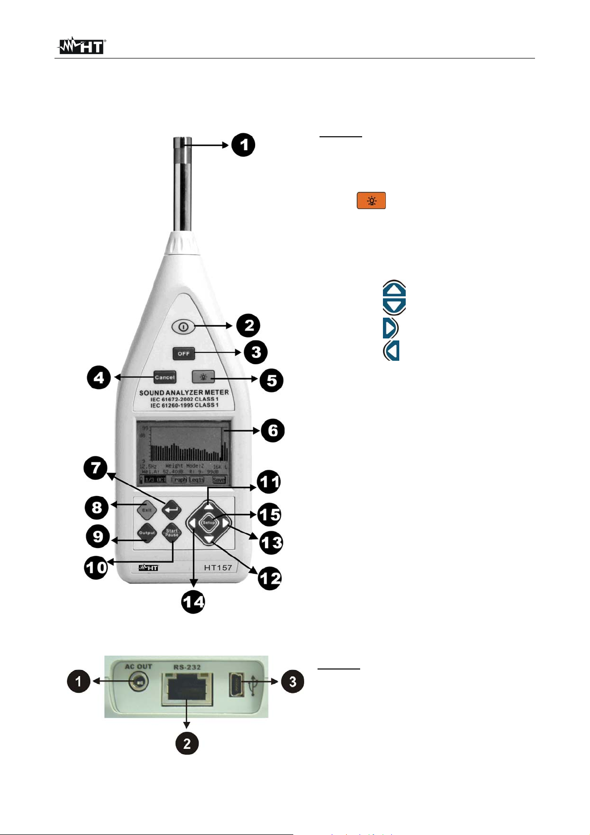
4.1.1. FRONT PANEL
LEGEND:
1. Microphone
2. ON key
3. OFF key
4. CANCEL key
5. Key to turn on the backlight
6. LCD display
7. ENTER key
8. EXIT key
9. OUTPUT key
10. START/PAUSE key
11. Arrow key for programming
12. Arrow key for programming
13. Arrow key for programming
14. Arrow key for programming
15. SETUP key for programming
Fig. 1: Description of the instrument’s front panel
4.1.2. OUTPUT INTERFACE
Fig. 2: Description of the output interface
EN - 6
LEGEND:
1. AC analogue output
2. RS-232 interface (not active)
3. Mini USB interface
Page 9
HT155 - HT157
A
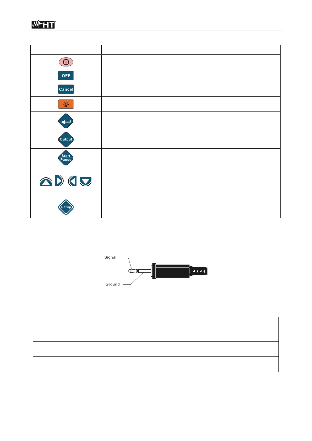
4.2. DESCRIPTION OF FUNCTION KEYS
Key Description
Pressing the ON key allows turning on and internally resetting
the instrument at any time
The OFF key allows turning off the instrument
The CANCEL key allows deleting the saved data from the
instrument’s memory
ctivates/deactivates the display’s backlight. Backlight turns off
automatically after 15s
The ENTER key allows entering the internal programming
screens and confirming the selections made
The OUTPUT key allows stopping the measurements and
automatically saving the result in the memory
The START/PAUSE key allows activating or pausing a
measurement
The arrow keys allow navigating the programming menu,
increasing/decreasing the parameter values by one unit (press
, , ,
and hold the keys for fast advance) and adjusting the display
contrast
The SETUP key allows rapidly accessing the programming
menu without passing from the main menu when a
measurement is in progress
4.3. ANALOGUE OUTPUT DESCRIPTION
The instrument is provided with an AC voltage analogue output proportional to the input
signal measured in dB, which can be used to connect a 3.5mm output jack with the
characteristics shown in Fig. 3
Fig. 3: Description of jack for AC analogue output
The proportion between the output and the input signal depends on the measuring range
of the instrument and is shown in the following table:
Gain range Output/input ratio Measuring range [dB]
-10dB 0.316 50~140
0dB 1 40~130
10dB 3.16 30~120
20dB 10 20~110
30dB 31.6 10~100
40dB 100 0~90
The impedance of the AC output signal is 1k. We recommend that the charge resistance
connected to the AC output is at least 100k and that the charge capacity is lower than
200pF. The ratio between the input and the output signal is 1mV / 0.1dB. The max output
voltage is 3.2V.
EN - 7
Page 10
HT155 - HT157
4.4. DISPLAY CONTRAST ADJUSTMENT
The instrument allows adjusting the display contract, proceeding as follows:
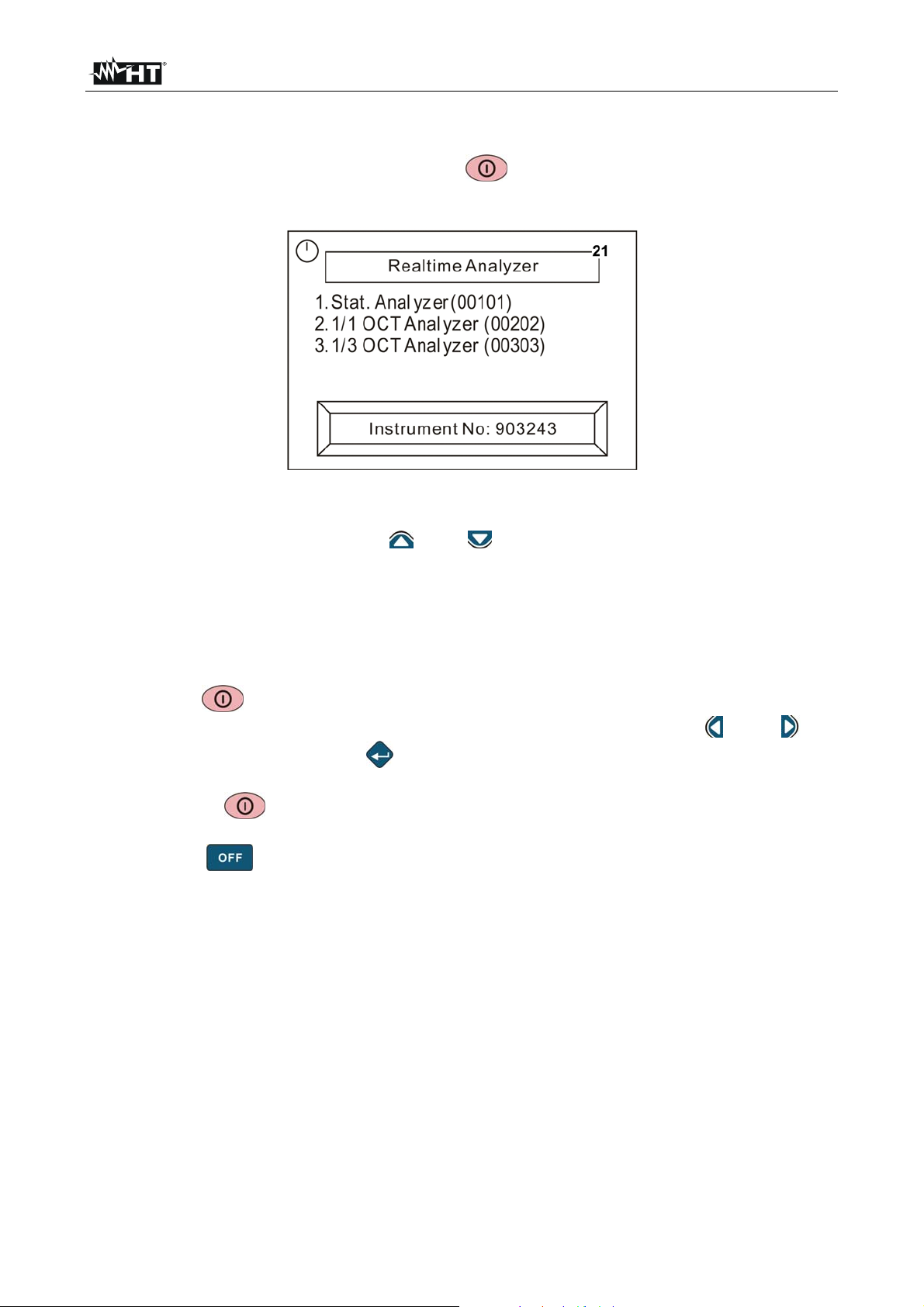
1. Turn on the instrument by pressing the key. The display shows the following
screen:
Fig. 4: Display contrast adjustment
2. Within 5s, press the arrow keys “ ” and “ ” respectively to decrease or increase the
contrast level of the display. This parameter is shown in the upper right-hand part of the
box “Realtime Analyzer”. Up to 30 contrast levels are possible
4.5. TURNING ON/OFF THE INSTRUMENT
Respect the following instructions when turning on and off the instrument
Press the key to turn on the instrument. The main screen in which the possible
measuring modes are listed is shown on the display. Use the keys “ ” and “ ” for
selecting and confirm with “ ”. If no key is pressed within 5s, the instrument
automatically sets itself to the last mode used
Pressing the
instrument back to the initial selection menu
Press the key to turn off the instrument. With the instrument turned off, the
instrument’s clock does not stop working thanks to the internal back-up battery. This
battery is continuously recharged when the instrument is measuring and at least 24
hours are necessary for a complete charge. With fully charged back-up battery, the
internal clock is maintained for over 3 months
The measurement results are saved in an internal flash memory and are always
maintained even with no external power supply or with the instrument turned off
key when measuring automatically resets the system and brings the
EN - 8
Page 11
HT155 - HT157
4.6. CONFIGURATION OF MEASURING PARAMETERS
4.6.1. FOREWORD
Before activating a recording operation, it is necessary to set the necessary parameters
such as the measure name, the measuring time, etc., on the instrument, starting from
section “Setup” of the main menu (see Fig. 5) or pressing the “ ” key inside a measuring
section. The instrument will automatically save the values of the parameters each time it is
turned off, subsequently recalling them each time it is turned on.
CAUTION
It is not possible to access the “Setup” section while the instrument is
recording
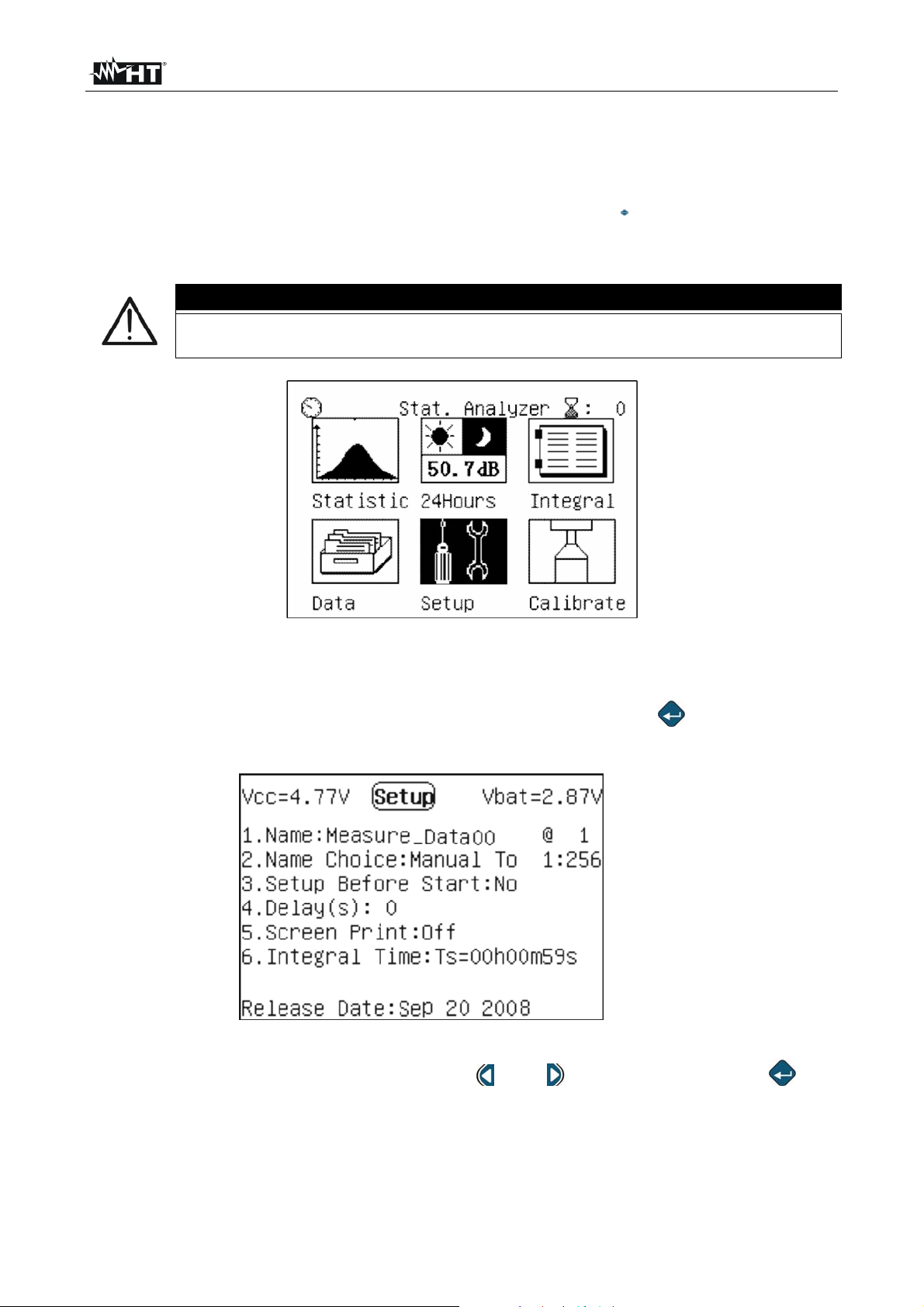
Fig. 5: Selection of the instrument’s SETUP section
4.6.2. PROGRAMMING MENU INTERFACE
Select the “Setup” section in the main menu and confirm with “ ”. The instrument
displays the screen shown in Fig. 6:
Line 1
Line 2
Line 3
Line 4
Line 5
Line 6
Line 7
Line 8
Fig. 6: Internal screen of programming menu
The single items can be selected by using the “ ” and “ ” keys and pressing the “ ” key
to modify the parameter values.
The following table contains the descriptions of the single lines contained in the
programming menu
EN - 9
Page 12
HT155 - HT157
On the left side of the line there is the voltage battery and on the right
Line 1
Line 2
Line 3
side the back-up battery voltage. In case the voltage value is > 10V, the
message “Over” will appear on the display
In this line, it is possible to select the name of measurement as a
reference for the data saved during the operation, choosing among a list
of names, which can be created by the user (see § 4.6.3), using the “ ”
and “ ” keys. The indication “@ 1” for example is the indication of the
first name available in the list
In this line it is possible to define, by using the “ ” and “ ” keys, a
criterion for the choice of the measure name. In particular, two modes are
available:
Auto mode the measure name is automatically changed by the
instrument each time a new measurement is started
Manual mode the measure name is not changed automatically by
the instrument and only the user can make the change
By using the “ ” and “ ” keys, it is possible to select the options:
Line 4
Line 5
Line 6
Line 7
Option No the instrument directly starts measuring when the “ ”
key is pressed
Option Yes before starting measuring, the instrument accesses the
Setup section when the “ ” key is pressed, so that the parameters
can be checked and/or changed. When the “ ” key is pressed, the
instrument starts measuring. This option is not available for the
“24Hours” operating mode
In this line it is possible to select, by means of the “
delay time (max 10s) for the activation of measurement after the “ ”
key is pressed. Value “0” indicates no delay. This option is not
available for the “24Hours” operating mode
In this line, by means of the “ ” and “ ” keys, it is possible to activate
(On) or deactivate (Off) the print of the values shown on the display by
means of a mini-printer connected to the RS-232 output, by pressing the
“ ” key. This function is not available
In this line it is possible to set the total measuring time, from 1s to 24
hours. The instrument allows rapidly setting, by means of the “ ” and
“ ” keys, the following 12 preset levels: 10s, 1min, 5min, 10min, 15min,
20min, 30min, 1h, 2h, 4h, 8h, 24h, or it is possible to set the desired
value by using the “ ” and “ ” keys to move to the “h”, “m” or “s” fields
and the “
” and “ ” keys to set the values
” and “ ” keys, a
Line 8 This line contains the date of the instrument’s Fw version
EN - 10
Page 13
HT155 - HT157
4.6.3. DEFINING THE MEASURE NAME
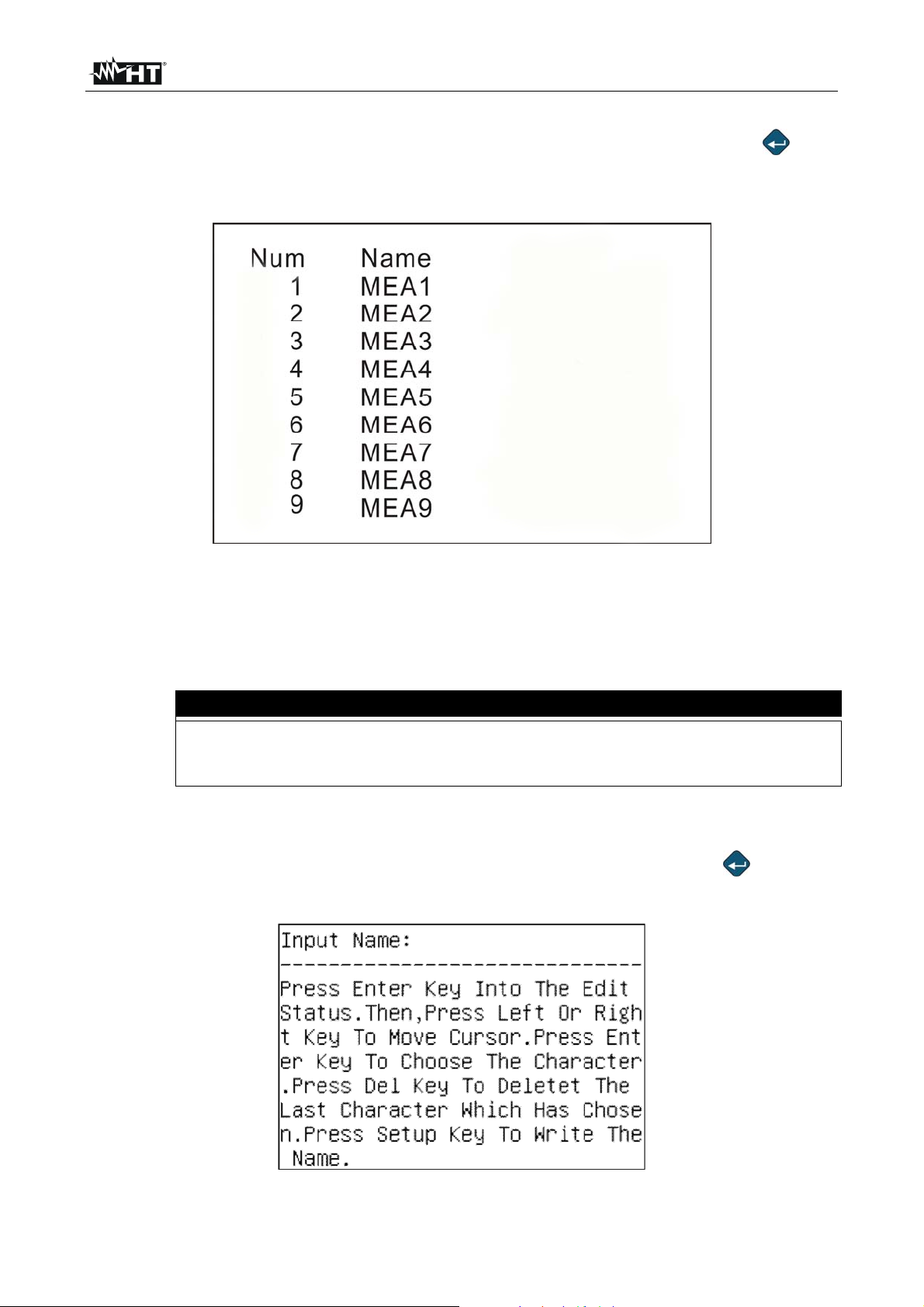
By selecting Line 3 inside the programming menu (see Fig. 6) and pressing the “ ” key,
the instrument displays the following screen, which shows a list of the measure names
created by the user:
Fig. 7: Screen containing the list of measure names
The first column, “Num”, refers to the number of the memory location used for saving the
measure name. The second column, “Name”, indicates the saved name, associated to the
relevant location
The instrument is capable of saving up to 256 measure names. If this
CAUTION
reference is exceeded, it automatically deletes all 256 names already
created, only saving the last input name
To create a new measure name, proceed as follows:
1. Select Line 2 inside the programming menu (see Fig. 6) and press the “
” key. The
instrument displays the following screen:
Fig. 8: Initial screen for setting the measure name
EN - 11
Page 14
HT155 - HT157
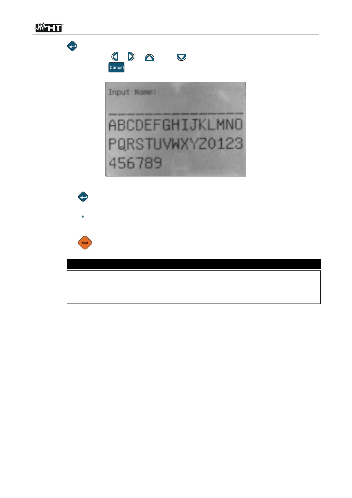
2. Press “ ” again to enter the next screen, where it is possible to digit the measure
name by using the “ ”, “ ”, “ ” and “ ” keys, for the selection of the available
characters, and the “ ” key to cancel the last input character.
Fig. 9: Screen for typing the measure name
3. Press the “ ” key to confirm each character of the measure name (m ax 14 characters
available)
4. Press the “ ” key to save the created measure name, which will be automatically
present in Line 2 of the programming menu, further to the number of the location
assigned to it.
5. Press the “ ” key to exit the programming menu
CAUTION
For a more rapid creation of the measure names, we recommend using the
provided software and to subsequently send these elements to the instrument
connected to the PC via USB interface. Deletion of the measure names on
the instrument is only possible via the software (see § 8.4.4)
EN - 12
Page 15
HT155 - HT157
5. CARRYING OUT MEASUREMENTS
The instrument is capable of carrying out different types of analyses of the sound pressure
level of a noise source:
1. Statistic analysis of noise
2. Spectrum analysis of noise with octave-band filter (1/1) (HT157 only)
3. Spectrum analysis of noise with third-octave band filter (1/3) (HT157 only)
For simplicity, the following descriptions are referred to the instrument model HT157
5.1. STATISTIC ANALYSIS OF NOISE
5.1.1. INITIAL OPERATIONS
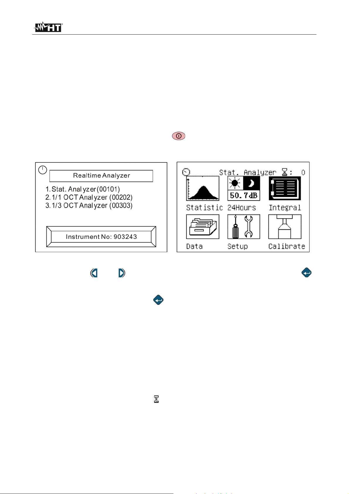
1. Turn on the instrument by pressing the “ ” key. The screen for the selection of the
analysis type is shown on the display for approximately 5s (see Fig. 10)
Fig. 10: Initial screens of statistic analysis
2. Use the keys “ ” and “ ” the option “Stat.Analyzer (00101)” and confirm with “ ”.
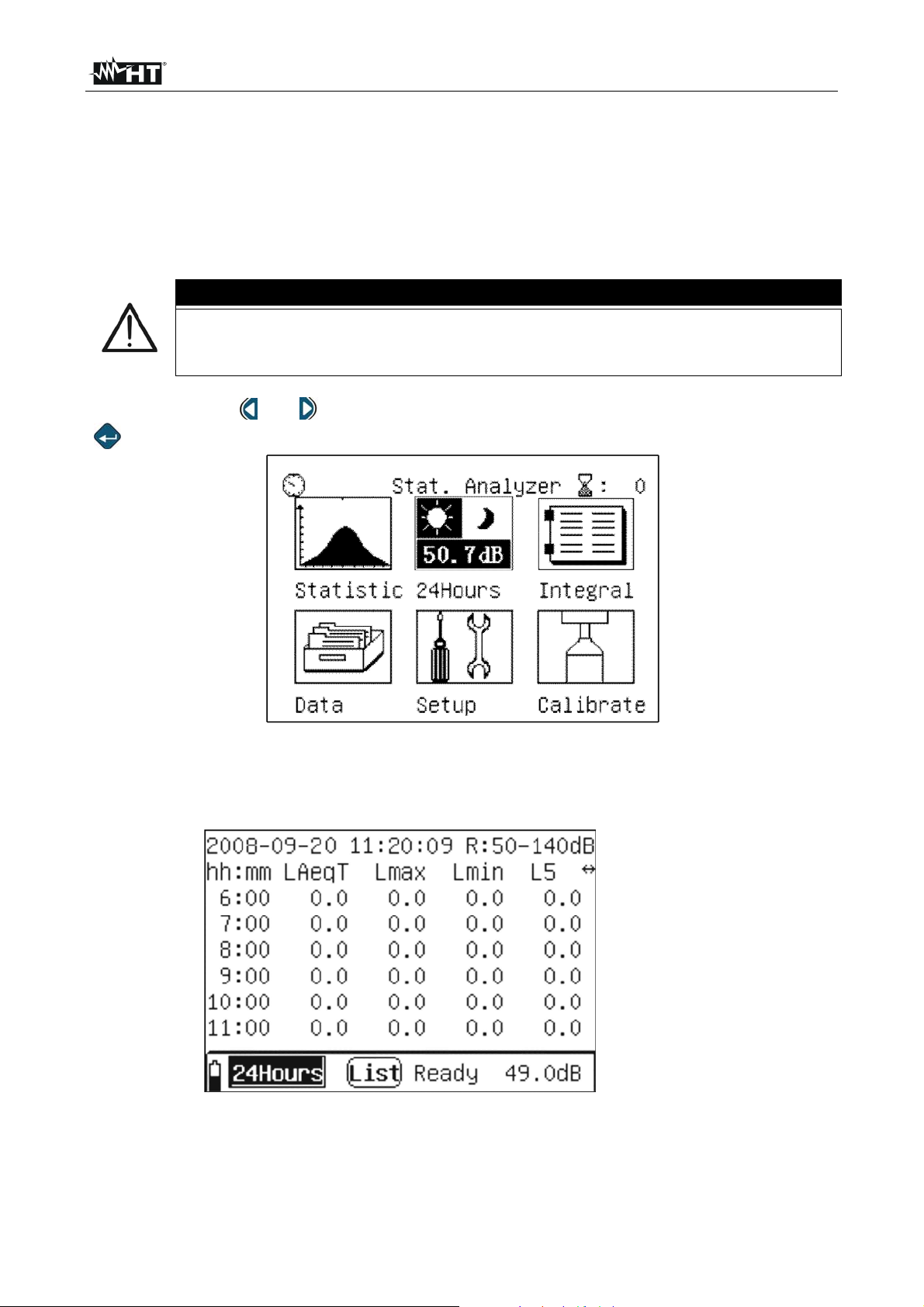
The instrument shows the main menu of the statistic analysis, consisting of 6 icons on
the display
3. Select the relevant icon and press “ ” to enter the specific menu. In detail:
Statistic the instrument measures the sound pressure level with weighting “A”,
with time constant Fast and equivalent noise level
24 Hours measurement of the sound pressure level in a fixed time period of 24
hours
Integral the instrument integrates the sound pressure level in the three frequency
weightings (A, C, Z) and in the three time constants (Slow, Fast, Impulse)
Data Section which contains the data of the recordings saved with the instrument
(see chapter 7)
Setup allows accessing the instrument’s programming menu (see § 4.6)
Calibrate section in which it is possible to calibrate the sensitivity level of the
microphone by using the provided portable calibrator HT151 (see § 6.1.3)
4. The indication next to the icon “ :XXX” in the right-hand top part of the display
indicates the number of the group of the datum which can be saved in the instrument’s
memory
EN - 13
Page 16
HT155 - HT157
5.1.2. STATISTIC ANALYSIS OPERATIONS
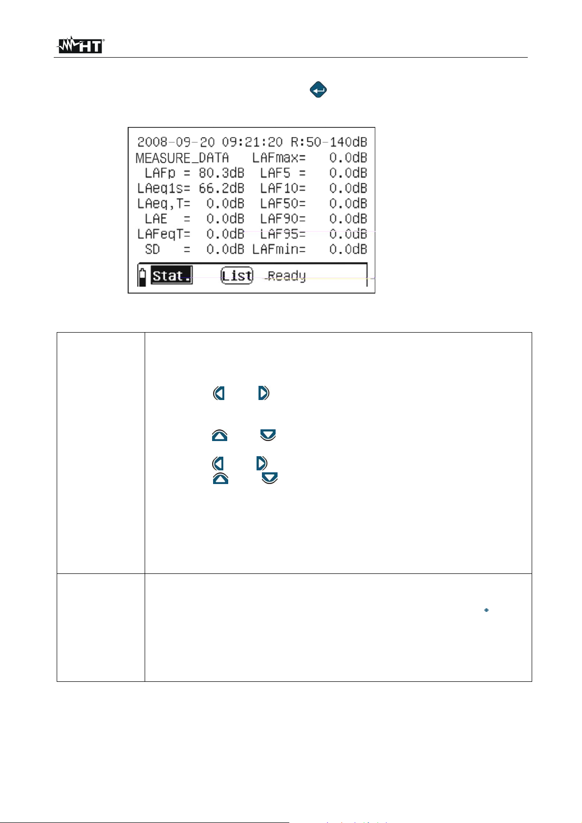
1. Select the “Statistic” icon and confirm with “ ”. The ins trument shows the following
screen relevant to the numerical display of the measured quantities
Line 1
Lines 2,8
Line 9
Fig. 11: Numerical screen of statistic analysis
The left part shows the current date/time set on the instrument, while the
right part shows the measuring range currently used by the instrument.
Both the parameters can be programmed by the user as follows:
Date/time setting
1. Use the “ ” and “ ” keys to move the flashing cursor to fields YYYY
(year), MM (month), DD (day), HH (hours), MM (minutes) SS
(seconds)
2. Use the “ ” and “ ” keys to select the desired program:
Line 1
Configuration of the measuring range
1. Use the “ ” and “ ” keys to move the flashing cursor to symbol “R”
2. Use the “
” and “ ” keys to select the measuring range among the
following options: 0 90dB, 10 100dB, 20 110dB, 30 120dB, 40
130dB, 50 140dB according to the reading carried out by the
instrument. After each range modification, the reading takes
approximately 3s to become stable
Lines 2 8
The central part of the display shows:
The measure name in the first 14 characters of the second line,
defined in the programming section (see § 4.6.3). Press the “ ” key to
change the measure name
The values of the measured quantities are updated in real time
every second. The following parameters, relevant to the sound
pressure level, are considered: LAFp, LAeq1s, LAeq,T, LAE, LAFeqT,
SD, LAFmax, LAF5, LAF10, LAF50, LAF90, LAF95, LAFmin
EN - 14
Page 17
HT155 - HT157
This line contains:
The “ ” icon, which indicates the battery charge level
The “ ” icon, which indicates the measuring mode. In the same
position, the following messages can be displayed: “OVER” and
“UNDER”, to indicate that the measured values are respectively higher
Line 9
and lower than the maximum and minimum range set. Operate on
Line 1 to change the measuring range value
The “ ” icon allows selecting the current numerical display or the
graphic display of data
The messages “Ready” (instrument ready for recording) “Run”
(instrument recording), “Pause” (instrument paused), “Save”
(instrument saving) or “End” (end of measuring campaign
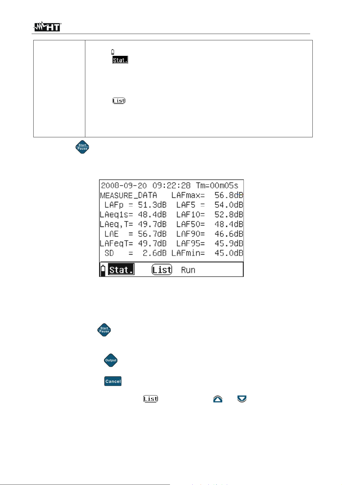
2. Press the “ ” key to start recording the values of the statistic analysis with a duration
equal to the total measuring time (Tm) defined in the programming menu (see § 4.6).
The instrument displays the following screen:
Fig. 12: Statistic analysis activation
3. The “Run” message appears in the lower part of the instrument, to indicate that a
recording is currently in progress. In this condition, the indication of the measuring
range disappears and the measuring time appears, and cannot be changed while
recording
4. By pressing the “ ” key while recording, the instrument is paused. The indication
“Pause” appears in the lower part of the instrument. Press the key a second time to
start recording again
5. When pressing the “ ” key with paused instrument, measurement is stopped and the
result is saved in the internal memory
6. When pressing the “ ” key with paused instrument, the measurement being carried
out is cancelled and the instrument waits for a new recording
7. With the flashing cursor on the “ ” icon, press the “ ” or “ ” keys to access the
graphic display of the measure. The instrument displays the following screen:
EN - 15
Page 18
HT155 - HT157
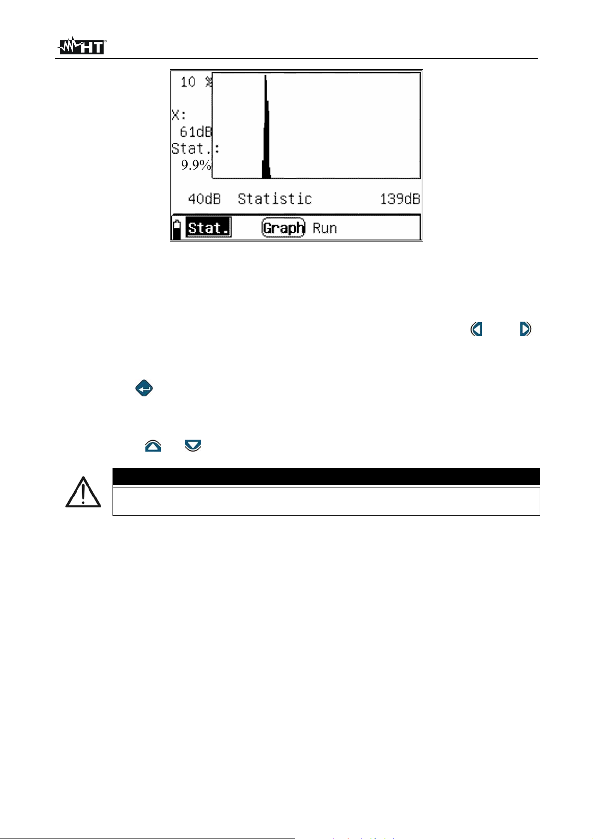
Fig. 13: Graphic screen of statistic analysis
8. The screen shows the diagram of the statistic distribution corresponding to the
recording in progress, with update every second. The left part of the graphic displays
the statistic percentage of the sound pressure level corresponding to the dB value
measured by the instrument, which can be changed by means of the “ ” and “ ”
arrow keys, within the measuring range reported on the x-axis. In the example in Fig.
13, the value of the sound pressure level is 61dB in 9.9% of the values measured
within the 40 – 139dB range.
9. Press the “ ” key to pass from the statistic distribution diagram to the cumulative
distribution diagram (Accumulation), which shows each statistic level of the noise
10. In the graphical screens, it is always possible to pause and/or stop recording in the
same way as with numerical display, which it is always possible to go back to by
pressing the “ ” or “ ” keys, with the cursor on the “Graph” icon
CAUTION
The main menu cannot be selected while recording. Cancel or stop recording
to carry out this operation
11. Once the measuring time has elapsed, the recording stops and the result is
automatically saved in the instrument’s memory. The “End” message appears in the
lower part of the instrument
EN - 16
Page 19
HT155 - HT157
5.1.3. 24-HOUR ANALYSIS OPERATIONS
The “24Hours” analysis is a statistic analysis, but has a fixed duration of 24 hours starting
from the programmable date/time, and divides the measuring results of the various
quantities in 24 intervals of one hour each. After the analysis has automatically stopped,
the calculated values of Ld, Ln and Ldn noise are also provided. This mode is appropriate
when it is necessary to repeat an analysis of a certain duration (measuring time) from the
same second of each hour during a whole day.
CAUTION
The measuring time within each interval can be set (see § 4.6.2) in a range of
1min 59min. For a measuring time different from this range, the instrument
automatically considers a time of 20min
1. Use the keys “ ” or “ ” to select the “24Hours” icon (see Fig. 14) and confirm with
”.
“
Fig. 14: Selection of 24Hours analysis
2. The instrument shows the following screen relevant to the measured quantities in
numerical form:
Line 1
Line 2
Lines 3-8
Line 9
Fig. 15: 24Hours analysis screen in numerical form
3. Consider the following table for the meaning of the items found in screen of Fig. 15:
EN - 17
Page 20

HT155 - HT157
The left part shows the current date/time set on the instrument, while the
right part shows the measuring range currently used by the instrument.
Both the parameters can be programmed by the user as follows:
Date/time setting
1. Use the “ ” and “ ” keys to move the flashing cursor to fields YYYY
(year), MM (month), DD (day), HH (hours), MM (minutes) SS
(seconds)
2. Use the “ ” and “ ” keys to select the desired program:
Line 1
Line 2
Lines 3- 8
Configuration of the measuring range
1. Use the “ ” and “ ” keys to move the flashing cursor to symbol “R”
2. Use the “ ” and “ ” keys to select the measuring range among the
following options: 0 90dB, 10 100dB, 20 110dB, 30 120dB, 40
130dB, 50 140dB according to the reading carried out by the
instrument. After each range modification, the reading takes
approximately 3s to become stable
By using the “ ” or “ ” keys to move the flashing cursor to the
“hh:mm” field and repeatedly using the “ ” or “ ” keys, the
instrument shows the 24 intervals from “0:00 to 23:00” and the values
of the Ld, Ln, Ldn parameters. By moving the cursor to the symbol “”
and pressing the “ ” or “ ” keys, the instrument shows the
following quantities in a horizontal line: LAeqT, Lmax, Lmin, L5, L10,
L50, L90, L95, SD, LAFeq, corresponding to the statistic analysis of
the sound pressure level with frequency weighting “A” and time
constant F
These lines show in real time the values of the quantities integrated by
the instrument during the whole measuring time and the resulting values
at the end of each interval
The left part of the line shows:
The “ ” icon, which indicates the battery charge level
The “
The “
(with flashing cursor on the icon, press the “
Line 9
4. With the message “Ready” on the display, press the “ ” key to enter the instrument’s
programming menu and set the relevant parameters (measure name, measuring time,
etc…) as described in § 4.6). Press the “ ” key to go back to the measuring screen
to graphic display “Graph”)
The messages “Ready”, “Run”, “Wait” or “End”, to respectively
indicate: waiting to start measuring, measurement in progress, waiting
to start measuring in new range and end of measurement
The indication in real time (e.g.: 49.0 dB) of the sound pressure level
measured by the instrument
” icon, which indicates the current operating mode.
” icon, to indicate the type of numerical display of the results
” or “ ” keys to pass
EN - 18
Page 21
HT155 - HT157
5. Press the “ ” key to start measuring. After this operation, the instrument:
Starts measuring from the minute indicated in the system date/time and shows this
reference in column “hh:mm” with the relevant values of the quantities read in real
time
Shows the message “Run” on the display
In line 1, it shows the measuring time “Tm” instead of the indication of the set range
Disables the possibility of accessing the programming menu by pressing the “ ” key.
Stops measuring to enter the programming menu again
6. Once the measuring time has elapsed, the instrument:
Shows the indication “Wait” on the display, to indicate that it is waiting to start
(instant “00”) in the new measuring interval at the hour following the initial one (see
) (e.g.: if measurement is started at 8:49, the second measurement will be started at
9:49:00)
Shows the measuring range again instead of the measuring time “Tm”
This operation is repeated for each of the remaining 24 intervals
Fig. 16: Screen of instrument waiting to start a new recording (Wait)
CAUTION
When a measurement is in progress (Run) or waiting (Wait), the
”,“ ”,“ ”,“ ”,“ ” keys are not active and it is necessary to stop or
“
cancel measurement to activate them again
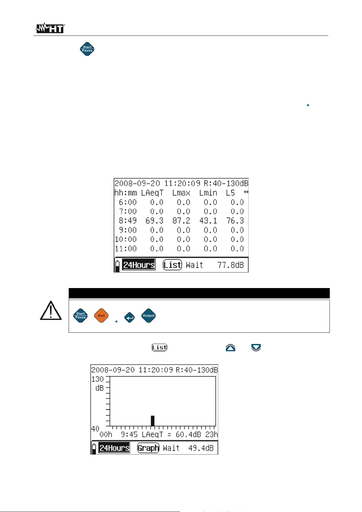
7. With the flashing cursor on the “ ” icon, press the “ ” or “ ” keys to access the
graphic display of the measure. The instrument displays the following screen:
Initial line
Central lines
Final line
Fig. 17: Screen of graphic display in 24Hours mode
EN - 19
Page 22

HT155 - HT157
The left part shows the current date/time set on the instrument, while the
right part shows the measuring range currently used by the instrument.
Initial line
Both parameters can be programmed, as with numerical display
By using the “ ” or “ ” keys to move the flashing cursor to the
“hh:mm” field and repeatedly using the “ ” or “ ” keys, the
Central lines
instrument shows the graphic values of the 24 intervals from “0:00 to
23:00”. By moving the cursor to one of the parameters (e.g.: LAeqT)
and by using the “ ” or “ ” keys, the instrument shows the graphic
values of the quantities exactly as for the numerical view
The left part of the line shows:
The “ ” icon, which indicates the battery charge level
The “ ” icon, which indicates the current operating mode.
The “Graph” icon, to indicate the type of graphic display of the results
” or “ ” keys to pass
Final line
(with flashing cursor on the icon, press the “
to numerical display “
”)
The messages “Ready”, “Run”, “Wait” or “End”, to respectively
indicate: waiting to start measuring, measurement in progress, waiting
to start measuring in new range and end of measurement
The indication in real time (e.g.: 49.0 dB) of the sound pressure level
measured by the instrument
8. Once the 24 intervals have elapsed, the recording stops and the result is
automatically saved in the instrument’s memory. The “End” message appears in the
lower part of the instrument (see Fig. 18). Each interval maintains the same name as
the measure
Fig. 18: Final display of 24Hours measure
9. To exit from the “24Hours” mode, press the “ ” key. The instrument shows the
message “Press Enter key to exit!”. Press “ ” to go back to the main menu. Press the
“
” key again to go back to the measuring mode
10. Once measurement is completed, press “
” to go back to the main menu
EN - 20
Page 23

HT155 - HT157
5.1.4. INTEGRATION ANALYSIS OPERATIONS
In this type of analysis, the instrument carries out an instant measurement, measures
integrated values and peak “C” values of the sound pressure level in the three frequency
weightings (A, C, Z) and in the three time constants (Slow, Fast, Impulse)
1. Use the “ ” or “ ” keys to select the “Integral” icon (see Fig. 19) and confirm with
“ ”.
Fig. 19: Integral analysis selection
2. The instrument shows the following screen relevant to the measured instant quantities:
Line 1
Lines 2-7
Line 8
Line 9
Fig. 20: Screen of instant values of Integral analysis
The left part shows the current date/time set on the instrument, while the
right part shows the measuring range currently used by the instrument.
Date/time setting
Use the “ ” and “ ” keys to move the flashing cursor to fields YYYY
(year), MM (month), DD (day), HH (hours), MM (minutes) SS (seconds)
and use the “ ” and “ ” keys to carry out the desired programming
Configuration of the measuring range
Line 1
Use the “ ” and “ ” keys to move the flashing cursor to symbol “R” and
use the “ ” and “ ” keys to select the measuring range among the
following options: 0 90dB, 10 100dB, 20 110dB, 30 120dB, 40
130dB, 50 140dB according to the reading carried out by the
instrument. After each range modification, the reading takes
approximately 3s to become stable
EN - 21
Page 24

HT155 - HT157
These lines show in real time the instant values of the following
quantities, measured by the instrument: LAFp, LCFp, LZFp, LASp,
Lines 2- 7
LCSp, LZSp, LAIp, LCIp, LZIp, LAeq1s, LCeq1s, LZeq1s
corresponding to the impulse levels of sound pressure with weightings A,
C, Z and time constants Slow (S), Fast (F) and Impulse (I)
The left part of the line shows a graphic bar, which dynamically updates
the values of the instant quantities: LAFinst, LASinst, LAIinst, LCFinst,
LCSinst, LCIinst, LZFinst, LZSinst, LZIinst found on the right part, by
Line 8
moving the cursor on one of them by means of the “ ” or “ ” keys and
selecting them by means of the “ ” or “ ” keys. Please note that each
segment of the graphic bar corresponds to 10dB within the selected
range
This line shows:
The “ ” icon, which indicates the battery charge level
The “ ” icon, which indicates the Integral mode selected
The “ ” icon, to indicate the type of instant display and the “Integ”
icon, to indicate the integration measurement
Line 9
The messages “Ready”, “Run”, “Finish” and “End” to indicate
respectively that the instrument is ready to carry out a recording
(Integr mode), that a recording is in progress, that a recording has
finished and that the whole operation has been completed
The “ ” icon which allows saving the values on the display in the
instrument’s memory
3. In the instant display, the following operations associated to the “ ” icon are
possible:
With cursor flashing on the “ ” icon, press the “ ” key to save the instant data
shown on the display in the memory area (see § ). During this operation, the “ ”
icon is completely highlighted for a few seconds, before it goes back to normal
display, to indicate correct saving
With the cursor flashing on the “ ” icon, press the “ ” or “ ” keys to instantly
select the “Lock” option. Subsequently, press the “ ” key to lock the quantity data
values shown on the display. Press “
With the cursor flashing on the “
select the “Max” option. By subsequently pressing the “
” again to exit the “Lock” function
” icon, press the “ ” or “ ” keys to instantly
” key, the instrument
shows the maximum value of the quantities shown on the display, and the value
automatically updates when a higher value is detected. Press “
” again to exit the
“Max” function
4. By using the “ ” or “ ” keys, the instrument goes to the following screen relev ant to
the integrated quantities:
EN - 22
Page 25

HT155 - HT157
Fig. 21: Screen of integrated values of Integral analysis
It allows setting the current date/time and the measuring range in the
Line 1
same way as for the instant value display
These lines show in real time the values of the following quantities
Lines 2- 7
integrated by the instrument: LAeqT, LCeqT, LZeqT, LAFmax, LAFmin,
LAFeqT, LASeqT, LAIeqT, LAE, E, Cpeak+, Cpeak-
Line 1
Lines 2-7
Line 8
Line 9
Line 8
programming menu (see § 4.6.2) and the measuring time “Tm”
5. Press the “ ” key to start the integration measurement. The instrument automatically
shows the screen with the integrated values (see Fig. 21) and the “Run” message
appears on the display
6. When the instrument reaches the measuring time (Tm = Ts), the instrument stops the
integration measurement and the “End” message appears on the display. Data are
automatically saved in the instrument’s memory
7. By pressing the “ ” key while a process is in progress, the instrument pauses
measurement and the “Pause” message appears on the display. In this situation:
By pressing the “ ” key, the instrument stops measuring, shows the “Finish”
message on the display and automatically saves the data up to that instant
In this line, the left part shows the duration of the “Ts” measure set in the
By pressing the “
” key, the measurement in progress is automatically cancelled
and the instrument goes back to the waiting condition, showing the “Ready”
message on the display
By pressing the “
” key again, the measurement starts again from the instant in
which it was stopped and the “Run” message appears on the display again
CAUTION
While a measurement is in progress (Run), it is not possible to access the
programming menu and it is necessary to first complete or stop it
The “ ” icon cannot be used for data integration measurement
EN - 23
Page 26

HT155 - HT157
5.2. NOISE ANALYSIS IN 1/1 AND 1/3 OCTAVE BAND (HT157 ONLY)
Further to the statistic analysis, the instrument HT157 allows carrying out accurate
measurements of the noise spectrum by using internal octave-band (1/1) and third-octaveband (1/3) filters
5.2.1. INITIAL OPERATIONS
1. Turn on the instrument by pressing the “ ” key. The screen for the selection of the
analysis type is shown on the display for approximately 5s (see Fig. 22)
Fig. 22: Initial screens for analysis in 1/1 and 1/3 octave band
2. Use the “
” or “ ” keys to select the item “1/1 OCT Analyzer (00202)” and press “ ”
to activate the octave band analysis (1/1) or the item “1/3 OCT Analyzer (00303)” and
press “ ” to activate the third-octave band analysis (1/3). The instrument shows the
main menu consisting of 6 icons on the display
3. Select the relevant icon and press “
” to enter the specific menu:
List the instrument shows, in numerical form, the sound pressure level for each
central band frequency in the range 16Hz 16kHz (1/1 analysis) and in the range
12.5Hz 16kHz (1/3 analysis) and the equivalent levels weighted A, C and Z
Graph the instrument shows the histograms of the 1/1 and 1/3 analyses
Total the instrument shows the whole of the data of the spectrum analysis
Data Section which contains the data of the recordings saved with the instrument
(see §)
Setup allows accessing the instrument’s programming menu (see § 4.6)
Calibrate section in which it is possible to make the initial calibr ation by using the
provided portable calibrator HT151 (see § 6.1.3)
4. The indication next to the icon “
:XXX” in the right-hand top part of the display
indicates the number of the group of the datum which can be saved in the instrument’s
memory
EN - 24
Page 27

HT155 - HT157
5.2.2. OCTAVE BAND ANALYSIS (1/1)
5.2.2.1. Operations for sections LIST, GRAPH and TOTAL
2. Select the “List” icon and confirm with “ ”. The instrument displays the following
numerical screen:
Line 1
Lines 2,8
Line 9
Fig. 23: Numerical screen of octave band analysis (1/1)
The left part shows the current date/time set on the instrument, while the
right part shows the measuring range selected.
Date/time setting
1. Use the “ ” and “ ” keys to move the flashing cursor to fields YYYY
(year), MM (month), DD (day), HH (hours), MM (minutes) SS
(seconds)
2. Use the “ ” and “ ” keys to select the desired program:
Line 1
Configuration of the measuring range
1. Use the “ ” and “ ” keys to move the flashing cursor to symbol “R”
2. Use the “ ” and “ ” keys to select the measuring range among the
following options: 0 90dB, 10 100dB, 20 110dB, 30 120dB, 40
130dB, 50 140dB according to the reading carried out by the
instrument. After each modification, the reading takes approximately
3s to become stable
The central part of the display shows the instant values of the sound
pressure level for each central band frequency from 16Hz to 16kHz,
Lines 2 8
further to the values of the equivalent noise levels Leq1s and Leq,T
updated in real time at each second. Also the values of parameters LA,
LC, LZ weighted in modes A, C and Z are shown
Line 8
This line contains:
The “ ” icon, which indicates the battery charge level
The “ ” icon which indicated the 1/1 measuring mode. In the
same position, the following messages can be displayed: “OVER” and
“UNDER”, to indicate that the measured values are respectively higher
and lower than the maximum and minimum range set. Operate on
Line 1 to change the measuring range value
The “ ” icon allows selecting the current numerical display, the
graphic display of data and the total display
The “Linst” shows the instant values, the “Leq1s” icon shows the
values of the level equivalent to 1s and the icon “Leq,T” shows the
values of the equivalent level of the whole measuring time
The “ ” icon which allows saving the values on the display
EN - 25
Page 28

HT155 - HT157
3. Press the “ ” key to start recording the values of the spectrum analysis 1/1 with a
duration equal to the total measuring time (Tm) defined in the programming menu (see
§ 4.6). In this condition, the indication of the measuring range disappears and the
measuring time appears, and cannot be changed while recording, and the “Leq,T” icon
appears automatically on the display. The instrument displays the following screen:
Fig. 24: Activation of recording of 1/1 spectrum analysis
3. By pressing the “ ” key while recording, the instrument is paused. Press the key a
second time to start recording again
4. When the instrument reaches the measuring time (Tm = Ts), the instrument stops the
integration measurement and the data are automatically saved in the memory
5. When pressing the “ ” key with paused instrument, measurement is stopped and the
result is saved in the internal memory
6. When pressing the “ ” key with paused instrument, the measurement being carried
out is cancelled and the instrument waits for a new recording
7. In the List and Leq1s display, the following operations associated to the “
” icon
are possible:
With cursor flashing on the “
shown on the display in the memory area (see § ). During this operation, the “
” icon, press the “ ” key to save the instant data
”
icon is completely highlighted for a few seconds, before it goes back to normal
display, to indicate correct saving
With cursor flashing on the “ ” icon, press the “ ” or “ ” keys to select the
“Lock” option. Subsequently, press the “
” key to lock the quantity data values
shown on the display. Press “ ” again to exit the “Lock” function
With cursor flashing on the “ ” icon, press the “ ” or “ ” keys to select the
“Max” option. By subsequently pressing the “ ” key, the instrument shows the
maximum value of the quantities shown on the display, and the value automatically
updates when a higher value is detected. Press “ ” again to exit the “Max” function
8. With cursor flashing on the “ ” icon, press the “ ” or “ ” keys to access the
“Graph” graphic display of the measure (or select the “Graph” icon in the main menu).
The instrument displays the following screen:
EN - 26
Page 29

HT155 - HT157
Fig. 25: Graphic screen of 1/1 spectrum analysis
9. The screen shows the histogram of the sound pressure level associated to the
frequency spectrum whose center is reported on the x-axis, further to the indications of
the frequency weightings A, C, and Z. The minimum and maximum values on the y-axis
are determined by the measuring range selection
10. Move the cursor to the line at the bottom of the x-axis and use the “ ” or “ ” keys to
select the spectrum frequencies. Observe the movement of a “music note” at the top of
the graph. Use the same keys to dynamically modify the measuring range.
11. For the remaining functions, please refer to the numerical display
12. With cursor flashing on the “ ” icon, press the “ ” or “ ” keys to access the
“Total” display of the measure (or select the “Total” icon in the main menu). The
instrument displays the following screen, relevant to the “Linst” item:
Fig. 26: Total section screen 1/1 spectrum analysis – Instant values
2. The initial part shows the system date/time and the measuring range which can be
modified by using the “
provides the instant values of the following sound pressure levels in frequency
weightings A, C, Z and with time constants Fast, Slow, Impulse: LAFp, LCFp, LZFp,
LASp, LCSp, LZSp, LAIp, LCIp, LZIp. Lines 7 and 8 show, in graphic bars, the instant
values of the quantities: LAFinst, LASinst, LAIinst, LCFinst, LCSinst, LCIinst,
LZFinst, LZSinst, LZIinst
3. Select the “ ” icon and confirm with “ ” to save the data in the instrument’s
memory
” or “ ” keys. In the five central lines, the instrument
EN - 27
Page 30

HT155 - HT157
CAUTION
The “Max” and “Lock” functions are not active for instant values shown in the
graphic bar
4. With flashing cursor on the “Linst” item, select the “Leq1s” options with the “ ” or
“ ” keys. The instrument shows the following screen relevant to the values of the
noise level equivalent to 1s:
Fig. 27: Total section screen 1/1 spectrum analysis – Leq1s values
5. Use the “Save” functions to save the screen on the display and the options “Lock” and
“Max” respectively to block the values on the display and show the maximum value of
the quantities
6. With flashing cursor on the “Linst” item, select the “Leq,T” options with the “ ” or “ ”
keys. The instrument shows the following screen relevant to the values of the
equivalent noise level:
Fig. 28: Total section screen 1/1 spectrum analysis – LeqT values
18. Press the “ ” key to start recording the values of the spectrum analysis 1/1 with a
duration equal to the total measuring time (Tm) defined in the programming menu (see
§ 4.6). In this condition, the indication of the measuring range disappears and the
measuring time appears, and cannot be changed while recording, and the “Leq,T” icon
appears automatically on the display
19. By pressing the “
” key while recording, the instrument is paused. Press the key a
second time to start recording again
20. When the instrument reaches the measuring time (Tm = Ts), the instrument stops the
integration measurement and the data are automatically saved in the memory
EN - 28
Page 31

HT155 - HT157
21. When pressing the “ ” key with paused instrument, measurement is stopped and the
result is saved in the internal memory
22. When pressing the “ ” key with paused instrument, the measurement being carried
out is cancelled and the instrument waits for a new recording
CAUTION
The main menu cannot be selected while recording. Cancel or stop
recording to carry out this operation
The “Max” and “Lock” functions are not active while recording values
EN - 29
Page 32

HT155 - HT157
5.2.3. ANALYSIS IN THIRD-OCTAVE BAND (1/3)
5.2.3.1. Operations for sections LIST, GRAPH
1. Select the “List” icon and confirm with “ ”. The instrument displays the following
numerical screen:
Line 1
Line 2
Lines 3,8
Line 9
Fig. 29: Numerical screen of analysis in third-octave band (1/3)
The left part shows the current date/time set on the instrument, while the
right part shows the measuring range selected.
Date/time setting
8. Use the “ ” and “ ” keys to move the flashing cursor to fields YYYY
(year), MM (month), DD (day), HH (hours), MM (minutes) SS
(seconds)
9. Use the “ ” and “ ” keys to select the desired program:
Line 1
Configuration of the measuring range
1. Use the “ ” and “ ” keys to move the flashing cursor to symbol “R”
2. Use the “ ” and “ ” keys to select the measuring range among the
following options: 0 90dB, 10 100dB, 20 110dB, 30 120dB, 40
130dB, 50 140dB according to the reading carried out by the
instrument. After each modification, the reading takes approximately
3s to become stable
Line 2
Lines 3-8
In this line, by using the “
” and “ ” keys, it is possible to select the
type of frequency weighting (A, C or Z) and the three pages (0, 1 and 2)
of the instant values of the sound pressure levels for each central band
frequency from 12.5Hz to 16kHz
These lines show the instant values of the sound pressure level for each
central band frequency from 12.5Hz to 160 Hz (page 0), from 200Hz to
2.5kHz (page 1) and from 3.15kHz to 16kHz (page 2), further to the
values of the parameters LA, LC, LZ with A, C and Z weighting (page 2)
EN - 30
Page 33

HT155 - HT157
This line contains:
The “ ” icon, which indicates the battery charge level
The “ ” icon which indicated the 1/3 measuring mode. In the
same position, the following messages can be displayed: “OVER” and
“UNDER”, to indicate that the measured values are respectively higher
and lower than the maximum and minimum range set. Operate on
Line 9
Line 1 to change the measuring range value
The “ ” icon allows selecting the current numerical display, the
graphic display of data and the total display
The “Linst” shows the instant values, the “Leq1s” icon shows the
values of the level equivalent to 1s and the icon “Leq,T” shows the
values of the equivalent level of the whole measuring time
The “
” icon which allows saving the values on the display
2. Press the “ ” key to start recording the values of the spectrum analysis 1/3 with a
duration equal to the total measuring time (Tm) defined in the programming menu (see
§ 4.6). In this condition, the indication of the measuring range disappears and the
measuring time appears, and cannot be changed while recording, and the “Leq,T” icon
appears automatically on the display. The instrument displays the following screen:
Fig. 30: Activation of recording of 1/3 spectrum analysis
3. By pressing the “
” key while recording, the instrument is paused. Press the key a
second time to start recording again
4. When the instrument reaches the measuring time (Tm = Ts), the instrument stops the
integration measurement and the data are automatically saved in the memory
5. When pressing the “
” key with paused instrument, measurement is stopped and the
result is saved in the internal memory
6. When pressing the “ ” key with paused instrument, the measurement being carried
out is cancelled and the instrument waits for a new recording
7. In List and Leq1s display, the following operations are possible:
With cursor flashing on the “ ” icon, press the “ ” key to save the instant data
shown on the display in the memory area (see § ). During this operation, the “ ”
icon is completely highlighted for a few seconds, before it goes back to normal
display, to indicate correct saving
EN - 31
Page 34

HT155 - HT157
With cursor flashing on the “ ” icon, press the “ ” or “ ” keys to select the
“Lock” option. Subsequently, press the “ ” key to lock the quantity data values
shown on the display. Press “ ” again to exit the “Lock” function
With cursor flashing on the “ ” icon, press the “ ” or “ ” keys to select the
“Max” option. By subsequently pressing the “ ” key, the instrument shows the
maximum value of the quantities shown on the display, and the value automatically
updates when a higher value is detected. Press “
” again to exit the “Max” function
13. With cursor flashing on the “ ” icon, press the “ ” or “ ” keys to access the
“Graph” graphic display of the measure (or select the “Graph” icon in the main menu).
The instrument displays the following screen:
Fig. 31: Graphic screen of 1/3 spectrum analysis
14. The screen shows the histogram of the sound pressure level associated to the
frequency spectrum whose center is reported on the x-axis, further to the indications of
the frequency weightings A, C, and Z. The minimum and maximum values on the y-axis
are determined by the measuring range selection
15. Move the cursor to the lines at the bottom of the x-axis and use the “ ” or “ ” keys to
select the spectrum frequencies and the type of frequency weighting A, C or Z. Use the
same keys to dynamically modify the measuring range. In graphic display, it is only
possible to select options Leq1s and Leq,T
16. For the remaining functions, please refer to the numerical display
EN - 32
Page 35

HT155 - HT157
5.2.3.2. Operations in TOTAL section
1. Select the “Total” item in the main menu (see Fig. 22) and confirm with “ ”. The
instrument displays the following screen, relevant to the “Linst” item:
Fig. 32: Total section screen 1/3 spectrum analysis – Instant values
2. The initial part shows the system date/time and the measuring range which can be
modified by using the “ ” or “ ” keys. In the five central lines, the instrument
provides the instant values of the following sound pressure levels in frequency
weightings A, C, Z and with time constants Fast, Slow, Impulse: LAFp, LCFp, LZFp,
LASp, LCSp, LZSp, LAIp, LCIp, LZIp. Lines 7 and 8 show, in graphic bars, the instant
values of the quantities: LAFinst, LASinst, LAIinst, LCFinst, LCSinst, LCIinst,
LZFinst, LZSinst, LZIinst
3. Select the “ ” icon and confirm with “ ” to save the data in the instrument’s
memory
CAUTION
The “Max” and “Lock” functions are not active for instant values shown in the
graphic bar
4. With flashing cursor on the “Linst” item, select the “Leq1s” options with the “ ” or
“
” keys. The instrument shows the following screen relevant to the values of the
noise level equivalent to 1s
Fig. 33: Total section screen 1/3 spectrum analysis – Leq1s values
EN - 33
Page 36

HT155 - HT157
5. Use the “Save” functions to save the screen on the display and the options “Lock” and
“Max” respectively to block the values on the display and show the maximum value of
the quantities
6. With flashing cursor on the “Linst” item, select the “Leq,T” options with the “ ” or “ ”
keys. The instrument shows the following screen relevant to the values of the
equivalent noise level:
Fig. 34: Total section screen 1/3 spectrum analysis – LeqT values
7. Press the “ ” key to start recording the values of the spectrum analysis 1/1 with a
duration equal to the total measuring time (Tm) defined in the programming menu (see
§ 4.6). In this condition, the indication of the measuring range disappears and the
measuring time appears, and cannot be changed while recording, and the “Leq,T” icon
appears automatically on the display
8. By pressing the “ ” key while recording, the instrument is paused. Press the key a
second time to start recording again
9. When the instrument reaches the measuring time (Tm = Ts), the instrument stops the
integration measurement and the data are automatically saved in the memory
10. When pressing the “
” key with paused instrument, measurement is stopped and the
result is saved in the internal memory
11. When pressing the “ ” key with paused instrument, the measurement being carried
out is cancelled and the instrument waits for a new recording
CAUTION
The main menu cannot be selected while recording. Cancel or stop
recording to carry out this operation
The “Max” and “Lock” functions are not active while recording values
EN - 34
Page 37

HT155 - HT157
6. INSTRUMENT ACOUSTIC CALIBRATION
6.1.1. FOREWORD
The instrument is regularly calibrated upon purchase and upon first use. The acoustic
calibration of the sensitivity level of the microphone is recommended in order to always
carry out correct tests at the beginning of each measuring campaign and must be carried
out by using the provided portable calibrator in Class 1 HT151, with an operating
frequency of 1kHz 1% and harmonic distortion <1%.
6.1.2. PRELIMINARY OPERATIONS
Select the “Calibrate” icon in any measuring mode and confirm with “ ”. The instrument
displays the following screen:
Line 1
Line 2
Line 3
Line 4
Line 1
Line 2
Line 5
Line 6
Fig. 35: Initial screen of calibration section
This line contains the serial number of the microphone, which is a readonly datum, not modifiable by the user
This line contains the field relevant to the free-field correction of the
microphone on the sound-level meter. To use the instrument with ½”
microphones, this parameter is 0.15dB at a frequency of 1kHz. To
change this value, proceed as follows:
Use the keys “
” or “ ” to select “Mod.” and confirm with “ ”. The
“Mod” field appears highlighted
Use the “ ” or “ ” keys to move the cursor to Line 2 and the “ ” or
” keys to define the value in steps of 0.1dB. Accordingly, also the
“
“App” field is highlighted
Move the cursor to the “App” field and press “ ” to confirm
This line contains the indication of the output sensitivity level of the
preamplifier of the microphone used by the instrument. The microphone
may need to be calibrated again in case the preamplifier is replaced,
because of the different gain and input capacitance values. Proceed as
follows:
Line 3
Use the keys “ ” or “ ” to select “Mod.” and confirm with “ ”. The
“Mod” field appears highlighted
Use the “ ” or “ ” keys to move the cursor to Line 3 and the “ ” or
“ ” keys to define the value in steps of 0.1dB. Accordingly, also the
“App” field is highlighted
Move the cursor to the “App” field and press “ ” to confirm
EN - 35
Page 38

HT155 - HT157
Line 4
Line 5
Line 6
This line indicated the sound pressure level set on the portable calibrator
HT151 during the calibration operation (see § 6.1.3)
This line shows the results of the calibration operation. When the
instrument is calibrated by means of frequency weighting type C, “Lpx=”
indicates the current sensitivity level of the microphone
This line contains the menu items which can be selected by the user
The “Rec.” option allows displaying the results of each calibration
operation
The “Cal.” Option allows activating the calibration procedure (see §
6.1.3)
The “App.” option is used for saving each setting defined by the user
during the manual adjustment procedures of the sensitivity levels
The “Mod.” option is used for the selection of the items relevant to the
manual adjustments of the sensitivity levels
EN - 36
Page 39

HT155 - HT157
6.1.3. ACOUSTIC CALIBRATION WITH CALIBRATOR HT151
CAUTION
For the first acoustic calibration of the instrument’s microphone, set the
sound pressure level (SPL) according to the values allowed by the portable
calibrator HT151 (94.0dB and 114.0dB). For values different from these
reference values, program the instrument as described in § 6.1.2
The portable calibrator HT151, which can be used to calibrate the sensitivity
of the microphones, guarantees a very steady performance level, compliant
with standard IEC 60492:2003 in Class 1
1. Turn on the instrument and select any operating mode, and wait f or a few s econds until
it reaches the operating temperature
2. Use the “ ” or “ ” to select the “Calibrate” icon and confirm with “ ” to enter the
calibration mode (see Fig. 35)
3. Set the value of the sound pressure level to 94.0dB or 114.0dB according to the values
available on the calibrator HT151 (see § 6.1.2 – Line 4) as follows:
Use the keys “ ” or “ ” to select “Mod.” and confirm with “ ”. The “Mod” field
appears highlighted
Use the “ ” or “ ” keys to move the cursor to Line 4 and the “ ” or “ ” keys to
define the value in steps of 0.1dB. Press and hold the keys for an increase/decrease
in steps of 1dB. Accordingly, also the “App” field is highlighted
Move the cursor to the “App” field and press “ ” to confirm the value
4. Insert the lower part of the portable calibrator HT151 into the ½” microphone of the
instrument until a click is heard (see Fig. 36)
Fig. 36: Insertion of the calibrator HT151 into the instrument
EN - 37
Page 40

HT155 - HT157
5. Press and hold the “ON” key on the calibrator HT151 to activate the level equal to
94.0dB, looking at the activation of the red LED on the calibrator. Press and hold both
“ON” and “+20dB” keys to activate the level equal to 114.0dB. Preliminarily check the
emission of the output sound of the calibrator. Otherwise, replace the internal battery
(see §
6. Select the “Cal.” option on the instrument (see Fig. 35) and press the “ ” key to
activate calibration, which takes 10s
7. Press and hold the key(s) on the calibrator and look at the count of the seconds from 0
to 9 in the left-hand top part of the instrument’s display. In the lower part of the display,
the indication “LpC” indicates the applied sound pressure level, approximately equal to
the difference between the value provided by the calibrator and the free-field correction
of the microphone, while “Lpx” indicates the current sensitivity level of the microphone
8. Move the cursor to the “App.” option and press the “ ” key to save the new sensitivity
level of the microphone in the memory
9. If the difference between the previous sensitivity level and the new level measured with
calibration is > 3dB, for a few seconds the instrument shows the message “The
difference between these two sensitivity is too large! Please affirm the calibration is
correct!” If so, repeat the calibration procedure and, if necessary, contact the customer
service, as the microphone could be damaged
10. Remove the calibrator HT151 from the instrument. The calibrator turns off automatically
when releasing the “ON” key
6.1.3.1. Replacing the calibrator battery
LEGEND:
1. Metal cover of battery compartment
2. “ON” key to turn on the calibrator and
red LED
3. “+20dB” key to activate the sound
pressure level of 114.0dB
4. Adapter for the insertion of a ½”
microphone
5. Internal cavity of the calibrator
Fig. 37: Replacing the calibrator HT151 battery
1. Fully unscrew the metal cover of the battery compartment
2. Extract the battery from inside the calibrator
3. Replace the battery with an equivalent one (see § 10.4)
4. Restore the metal cover of the battery compartment into place and screw it in
EN - 38
Page 41

HT155 - HT157
6.1.3.2. Calibration result display
The instrument allows saving up to 256 calibration operations. For subsequent operations,
the memory space is automatically reset and only the last operation carried out is saved.
To recall the operation on the display, proceed as follows:
1. Use the keys “ ” or “ ” to select “Rec.” and confirm with “ ”. The instrument shows
the following screen, which contains the date/time in which the operation was carried
out and the measured sensitivity level
Fig. 38: Calibration result display
2. Use the “ ” or “ ” keys to go to the screens on the following pages
3. Press the “ ” key to exit the mode and to go back to the previous page
6.1.4. DIRECT ACOUSTIC CALIBRATION
In case the calibrator is not available and with an a priori known indication of the sensitivity
level of the microphone, this parameter can be set directly on the instrument as follows:
1. Use the keys “ ” or “ ” to select “Mod.” and confirm with “ ”. The “Mod” field
appears highlighted
2. Use the “
define the value in steps of 0.1dB. Press and hold the keys for an increase/decrease in
steps of 1dB. Accordingly, also the “App” field is highlighted
3. Move the cursor to the “App” field and press “
” or “ ” keys to move the cursor to Line 3 and the “ ” or “ ” keys to
” to confirm the sensitivity level
EN - 39
Page 42

HT155 - HT157
7. OPERATIONS WITH THE MEMORY
The instrument is provided with an internal Flash memory with a capacity of 64Kbytes for
saving data. Each saved measure can have a maximum size of up to 512 bytes, and
therefore it is possible to save up to 128 measure groups. The saved data can be
transferred onto the provided USB pen or transferred to the PC via USB connection and
analyzed with the provided software. Each measure can be recalled on the instrument’s
display.
7.1. RECALLING RESULTS ON THE DISPLAY
1. Select the “Data” icon in any measuring mode (see Fig. 39) and confirm with “ ”
Fig. 39: Selection of memory data viewing mode
2. The instrument shows the following screens, which can be selected by using the “ ”
and “ ” keys
Fig. 40: Screens of saved data
Num Indicates the number of the used memory location
Name Indicates the measure name defined by the user
Date Indicates the date in which the measure was saved
Time Indicates the time in which the measure was saved
Mode Indicates the type of measure saved
STA statistic data analysis
INT data of an integration measurement inside the statistic analysis
24Hxx data of the “24Hours” measurement inside the statistic analysis. The two
characters “xx” indicate the number of the saved interval
OCT indicates the octave band analysis (1/1)
1/3OCT indicates the 1/3 octave band analysis (1/3)
ALL indicates the total analysis of results
3. Use the keys “
” or “ ” for selecting the desired measure and confirm with “ ”.
Press “ ” to go back to the main menu
EN - 40
Page 43

HT155 - HT157
7.1.1. RECALLING THE STATISTIC ANALYSIS DATA ON THE DISPLAY
1. Select a datum corresponding to the “STA” indication available in the list of saved
measures and press “ ”. The instrument displays the following screen:
Line 1
Line 2
Line 3
Line 4
Lines 5-10
Fig. 41: Numerical display of "STA" analysis data
Line 1
This line shows the measure name defined in the programming menu
(see § 4.6)
Line 2 This line shows the date/time when measurement was started
Line 3
This line shows the type of “STA” measurement and the measuring time
defined in the programming menu (see § 4.6)
Line 4 This line shows the measuring range selected before starting measuring
Lines 5-10 These lines show the numerical values measured by the instrument
2. Press the “ ” key to view the graphic trend of the statistic analysis and “ ” again to
view the cumulative values of distribution
Fig. 42: Graphic display of "STA" analysis values
3. By using the “” or “” keys, it is possible to move the cursor on the x-axis, scrolling the
values within the selected measuring range
4. Press the “
” key again to go back to numerical display or the “ ” key to go back to the
initial screen
EN - 41
Page 44

HT155 - HT157
7.1.2. RECALLING THE 24H ANALYSIS DATA ON THE DISPLAY
1. Select a datum corresponding to the “24H” indication available in the list of saved
measures and press “ ”. The instrument displays the following screen:
Line 1
Line 2
Line 3
Line 4
Lines 5-10
Fig. 43: Initial numerical display of "24H" analysis data
Line 1
This line shows the measure name defined in the programming menu
(see § 4.6)
Line 2 This line shows the date/time when measurement was started
This line shows the type of “24Hxx” measurement, where “xx” stands for
Line 3
the number of intervals considered (max 24), and the measuring time
defined in the programming menu (see § 4.6)
Line 4 This line shows the measuring range selected before starting measuring
Lines 5-10 These lines show the numerical values measured by the instrument
2. Press the “ ” key to display in detail the value of each interval considered (e.g.: 8
intervals in Fig. 45). Press the “ ” or “ ” keys to go to the next pages and the “” or “”
keys to display the values of parameters Ld, Ln and Ldn
Fig. 44: Detailed display of "24H" analysis intervals
3. Press the “ ” key again for a graphic histogram display of the distribution of the
measured values for each interval
EN - 42
Page 45

HT155 - HT157
Fig. 45: Display of distribution graphic of the "24H" analysis values
4. Press the “ ” or “ ” keys to go to the next pages and the “” or “” keys to display the
values of data in the single intervals
5. Press the “
initial screen
” key again to go back to numerical display or the “ ” key to go back to the
EN - 43
Page 46

HT155 - HT157
7.1.3. RECALLING THE INTEGRATION MEASUREMENT DATA ON THE DISPLAY
1. Select a datum corresponding to the “INT” indication available in the list of saved
measures and press “ ”. The instrument displays the following screen:
Line 1
Line 2
Line 3
Line 4
Lines 5-10
Fig. 46: Initial page display of "INT" analysis data
Line 1
This line shows the measure name defined in the programming menu
(see § 4.6)
Line 2 This line shows the date/time when measurement was started
Line 3 The type of “INT” measurement is shown
Line 4 This line shows the measuring range selected before starting measuring
Lines 5-10 These lines show the numerical values measured by the instrument
2. Press the “” key to access the final page. The instrument shows the following screen,
which also indicates the measuring time defined in the programming menu (see § 4.6)
Fig. 47: Final page display of "INT" analysis data
3. Press the “” key to go back to the previous screen or the “ ” key to go back to the initial
screen
EN - 44
Page 47

HT155 - HT157
7.1.4. RECALLING THE DATA OF THE OCTAVE BAND ANALYSIS (1/1) ON THE
DISPLAY
1. Select a datum corresponding to the “OCT” indication available in the list of saved
measures and press “ ”. The instrument shows the following screens, which can be
selected by using the “” or “” keys
Fig. 48: Numerical screens of 1/1 analysis data
Line 1 (Page1)
Line 2 (Page1) This line shows the date/time when measurement was started
Line 3 (Page1) The type of “OCT” measurement is shown
Line 4 (Page1) This line shows the measuring range selected before starting measuring
Lines 5-10
2. Press the “
The instrument displays the following screen:
This line shows the measure name defined in the programming menu
(see § 4.6)
These lines show the numerical values measured by the instrument,
divided into each central band frequency considered
” key to access the graphic display of the spectrum octave band analysis.
Fig. 49: Graphic display of 1/1 spectrum analysis
3. Press the “ ” key to go back to the previous screen and to the initial screen
EN - 45
Page 48

HT155 - HT157
7.1.4.1. Recalling the data of the analysis in Total octave band (1/1)
Within the “OCT” analysis, it is possible to display the following screens relevant to the
“TOTAL” function, which considers the whole of the data:
Fig. 50: Display of "TOTAL" analysis data
Line 1 (Page1)
This line shows the measure name defined in the programming menu
(see § 4.6)
Line 2 (Page1) This line shows the date/time when measurement was started
Line 3 (Page1) The type of “ALL” measurement is shown
Line 4 (Page1) This line shows the measuring range selected before starting measuring
Lines 5-10
These lines show the values of the sound pressure levels, both instant
and relevant to integrations carried out with programmable time
EN - 46
Page 49

HT155 - HT157
7.1.5. RECALLING THE DATA OF THE ANALYSIS IN THIRD-OCTAVE BAND (1/3) ON
THE DISPLAY
1. Select a datum corresponding to the “1/3OCT” indication available in the list of saved
measures and press “ ”. The instrument shows the following screens, which can be
selected by using the “” or “” keys
Fig. 51: Numerical screens of 1/3 analysis data
Line 1 (Page1)
This line shows the measure name defined in the programming menu
(see § 4.6)
Line 2 (Page1) This line shows the date/time when measurement was started
Line 3 (Page1) The type of “1/3OCT” measurement is shown
Line 4 (Page1) This line shows the measuring range selected before starting measuring
These lines show the numerical values measured by the instrument
Lines 5-10
(Leq1s o Leq,T), divided into each central band frequency, f0 (Hz),
considered
CAUTION
Independently from the type of frequency weighting selected for measurement,
the saved data include anyway also the results obtained with Z (Zero)
weighting
2. Press the “ ” key to access the graphic display of the spectrum analysis in 1/ 3 octave
band. The instrument displays the following screen:
Fig. 52: Graphic display of 1/3 spectrum analysis
3. Press the “ ” key to go back to the previous screen and to the initial screen
EN - 47
Page 50

HT155 - HT157
7.2. DATA TRANSFER ONTO USB PEN DRIVE
CAUTION
Transferring the data contained in the instrument’s memory onto an external
USB pen drive unit is guaranteed only when using the USB pen drive
provided with the instrument. This does not exclude, however, that
appropriately formatted USB pen drives can be used.
1. Select section “Data” in the main menu and confirm with “ ”, when entering the
instrument’s memory area (see Fig. 40)
2. Press the “ ” key. The instrument shows the message “Please insert Usb-Disk…..” on
the display
3. Insert the provided USB pen drive into the relevant USB port on the instrument, by
using the appropriate connection cable provided
4. After a few moments, the instrument checks the initialization of the connected pen drive
and verifies if the necessary space for a correct data transfer is available. In case of
insufficient memory space in the USB pen drive, the instrument shows a message on
the display.
5. After transfer is completed, the instrument shows the same screen as in section “Data”
(see Fig. 40)
6. In the USB pen drive, the instrument creates a subfolder in the main root with a name
equal to the date of transfer and, inside it, there are files with extension *.TXT with a
name consisting of the first 6 letters of the names of the files defined upon recording
plus two letters corresponding to the memory location where they were saved in the
instrument. These files contain the data of the performed recordings
7. Extract the USB pen drive and connect it to the PC for data display
8. Press “ ” to go back to the main menu of the instrument
EN - 48
Page 51

HT155 - HT157
8. OPERATIONS WITH SOUNDVIEW SOFTWARE
8.1. FOREWORD
The SoundView Windows software provided with the instrument allows carrying out the
following operations:
Downloading the data of the recordings carried out with the instrument connected to the
PC via USB interface
Read and analyze the saved data and customize them into PC folders with names
defined by the user, which is not possible by operating directly on the instrument itself
Define, in a simple way, the names of the measurements and send them directly to the
instrument
Display the data of the analyses in numerical and graphic format
Download the results of the calibration operations carried out on the instrument
Export the data of the recordings in Excel file format
Copy and print directly the data downloaded by the instrument to PC
8.2. MINIMUM SYSTEM REQUIREMENTS
The following characteristics are necessary for a correct installation and use of the
software
Processor Pentium III 500MHz or higher
RAM memory: 128Mbytes
100Mbytes of free space available on HD
Operating system Windows 2k or higher
8.3. INSTALLING THE DRIVER USB
When connecting the instrument to the PC for the first time via an USB port of the PC, it is
necessary to install the USB driver, so that the instrument can be recognized. To this
purpose, proceed as follows (e.g.: Windows XP operating system):
1. Turn on the instrument in any screen
2. Connect the instrument to an USB port of the PC by means of the supplied cable
3. The PC shows the following screen:
4. Select the option “Install from list or specific location” in order to select the driver from a
specific folder and click on the “Next” key. The PC shows the following screen:
EN - 49
Page 52

HT155 - HT157
5. Press the “Browse” key and select the folder …\Sound Meter usb driver\ inside the
USB pen drive provided (after saving the content of the pen drive on the HD of the PC).
Press “Next”
6. Select the file with extension “ch375wdm.inf” and proceed with “Next”
7. The installation procedure of the driver is started by the PC
8. Press “Finish” to stop the installation procedure of the USB driver
EN - 50
Page 53

HT155 - HT157
8.4. USE OF SOUNDVIEW SOFTWARE
After installing the software from the file “Setup.exe” contained in the USB pen drive
provided with the instrument, launch the program. The PC shows the following screen:
Fig. 53: Initial software screen
8.4.1. COPY AND PRINT COMMANDS
With a open measure shown to PC (command “Input Data” of File menu), perform a right
click on measure name the “Copy” and “Print” are available on program
Fig. 54: Use of Copy and Print commands
Copy A copy of graph and numerical data of current measure in a XLS file is performed
Print The direct print of graph and numerical data of current measure is performed
EN - 51
Page 54

HT155 - HT157
8.4.2. FILE MENU
This menu contains the following controls:
Control Description
Input Name (CTRL+N)
Key
Input Data (CTRL+D)
Key
Setup (CTRL+Z)
Key
It allows opening a file with extension (*.XLS) relevant to a
defined measure name, available inside the PC (see § 8.4.4)
It allows selecting a folder in the PC, in which there are
analyses downloaded from the instrument (corresponding to
files with *.TXT extension)
It allows selecting the communicating mode (USB) between
instrument and PC (the option “Serial Port” is not active)
and the path in which to save the data of the recordings
downloaded from the instrument (Path). Press SAVE to
confirm
It allows exporting all the measures currently open in an
Excel file format (*.XLS). The software allows defining the
name of a folder and the saving path of the file
Export to XLS
“Conversion.xls” automatically created
Exit (CTRL+E) It allows exiting the program
EN - 52
Page 55

HT155 - HT157
8.4.3. VIEW MENU
In this menu there are the following controls, which can be activated by the user in order to
carry out the operations more rapidly:
Toolbar it allows displaying/hiding the toolbar
Status bar it allows displaying/hiding the status bar
Work Space it allows displaying/hiding the work space
8.4.4. NAME MENU
This menu contains the following controls:
Control Description
Read Out (CTRL+C)
It allows viewing the list of the measure names defined by the
user on the instrument in section “Measure Name” of the
Key
program
It allows adding a custom measure name which can be
viewed in section “Measure Name” of the program and which
can be sent to the instrument. The provided program opens
the following window, in which it is possible to digit the
desired name, confirming with “Add”
Add (CTRL+A)
Key
Write In (CTRL+R)
Key
Save (CTRL+B)
Key
Clear (CTRL+U)
Key
It allows sending to the instrument the whole list of the
measure names defined by the user, which can be viewed in
section “Measure Name” of the program Before carrying out
this operation, the program shows the following window:
where it is necessary to put in the instrument’s serial number
(on the rear side of the instrument itself) in the same format
as it is written on the label (e.g.: “8C0001” is correct, while
“8c0001” is not)
Upon correct activation of the control, the instrument turns off
and on again automatically, and a confirmation message is
provided by the program
It allows saving the measure name defined by the user with
extension *.XLS in a folder on the PC
It allows deleting each measure name inside the
instrument. In this condition, the program first of all requires
that the serial number is correctly put in, then sends the
control to the instrument, which turns off and on again
automatically, to confirm that the operation has been
correctly carried out
EN - 53
Page 56

HT155 - HT157
8.4.5. RESULT MENU
This menu contains the controls which allow transferring the recorder data from the
instrument, analyzing the data and clearing all data from the instrument’s memory
Control Description
It allows downloading the instrument’s memory content onto
the PC. According to the type of analysis, the downloaded
Read Results (CTRL+J)
Key
Realtime Analyze Command not active
Clear Results (CTRL+F)
8.4.6. CALIBRATION MENU
This menu contains the controls to manage the information relevant to the calibrations
performed on the instrument by using the portable calibrator HT151 (see § 6.1.3)
Control Description
data will appear in section “Measure Data” as TXT file and
will be shown both in graphical and in numerical format in the
working space. Defining the path where the file must be
saved is possible by using the “Setup” control (see § 8.4.1)
It allows clearing the whole instrument’s memory content.
Before carrying out this operation, the program requires that
the instrument’s serial number is correctly put in
Read Cal (CTRL+X)
Key
View Cal (CTRL+W)
Key
Clear Cal (CTRL+V)
8.4.7. HELP MENU
It provides information on the program’s version
It allows saving on the PC the list of the calibrations
contained in the instrument’s memory in a file with extension
*.CAL
It allows opening a fine with extension *.CAL available in the
PC
It allows deleting the whole list of calibrations available in the
instrument’s memory. Before carrying out this operation, the
program requires that the instrument’s serial number is
correctly put in
EN - 54
Page 57

HT155 - HT157
9. MAINTENANCE
9.1. GENERAL INFORMATION
The instrument You purchased is a precision instrument. During use and storage, carefully
observe the recommendations listed in this manual in order to prevent possible damage or
dangers during use.
Do not use the instrument in environments with high humidity levels or at high
temperatures. Do not directly expose to sunlight.
Always turn off the instrument after use. If the instrument is not to be used for a long time,
remove the battery to prevent any leaks of liquids which could damage the instrument’s
internal circuits.
9.2. REPLACING THE BATTERIES
When the LCD display shows the symbol ” ” and the message “BATTERY LOW”, it is
necessary to replace the internal batteries
Fig. 55: Replacement of internal batteries
1. Turn off the instrument.
2. Open the battery compartment.
3. Removed the old batteries (see Fig. 55)
4. Insert new batteries of the same type (see § 10.5), respecting the indicated polarities.
5. Close the battery compartment.
6. Do not scatter old batteries in the environment. Use the appropriate containers for
disposal.
9.3. CLEANING THE INSTRUMENT
To clean the instrument, use a soft dry cloth. Never use humid cloths, solvents, water, etc.
9.4. END OF LIFE
WARNING: the symbol reported on the instrument indicates that the appliance,
its accessories and the battery must be disposed of separately and treated
correctly.
EN - 55
Page 58

HT155 - HT157
10. TECHNICAL SPECIFICATIONS
10.1. TECHNICAL SPECIFICATIONS
Uncertainties are referred to a temperature of 23°C±5°C with relative humidity <80%UR
Measuring range
Weighting type A: 25 140dB
Weighting type C: 30 140dB
Weighting type Z: 35 140dB
SLM level Peak C: 50 143dB
Ranges [dB]
Weighting A
Weighting C
Weighting Z
Peak C
For sensitivity values <50mV/Pa, the measuring range is higher. For
example, with a microphone with a sensitivity of 40mV/Pa (-28dB), the
measuring range increases by 2dB and the reference value on the display
passes to range 42 132dB
We recommend using a ½” pre-polarized microphone with a sensitivity of
50mV/Pa, frequency range: 10Hz 20kHz, basic noise <16dB(A)
Linear dynamic range: >90dB
Resolution: 0.1dB (statistic), 0.01dB (1/1 and 1/3 octave)
Frequency range: 10Hz 20kHz (0.2dB); 1Hz 23kHz (1.0dB)
Gain range: -10dB, 0dB, 10dB, 20dB, 30dB, 40dB
Internal error: 0.1dB
Internal noise voltage: <4V (1Hz 23kHz linear)
Background noise: <13dB(A), 15dB(C), 25dB(Z)
Total noise: <18dB(A), 23dB(C), 28dB(Z)
Voltage measuring range: 15V 10V (TRMS)
Frequency weighting: A/C/Z
Time constants: Fast, Slow, Impulse, Peak C+, Peak C-
Internal A/D converter: 24 bits
Anti-aliasing filter: cut-off frequency 23.5kHz, attenuation 100dB
Sampling frequency: 20.8s (48kHz)
Integration time: 1s 24h at preset or custom intervals
Internal memory: 64kByte flash memory
Memory capacity: max 128 groups/ max 256 calibrations
Analogue output: AC, ratio 1mV/0.1dB, max voltage 3.2V
Output interface: mini-USB 1.1 and 2.0 compatible
Connection to USB pen drive: recommended TRASCEND JF V30 2GB
Microphone: ½” with prepolarized condenser with pre-amplifier,
0 90 10 100 20 110 30 120 40 130 50 140
25 90 25 100 25 110 30 120 40 130 50 140
30 90 30
100 30 110 30 120 40 130 50 140
35 90 35 100 35 110 35 120 40 130 50 140
50 93 50 103 50 113 50 123 60 133 70 143
CAUTION
sensitivity: 50mV/Pa, frequency range:
10Hz20kHz, noise <16dB(A)
EN - 56
Page 59

HT155 - HT157
10.2. STATISTIC ANALISYS CHARARCTERIS TICS
Functions: SLM statistic analysis in weighting A
Frequency integration with programmable period
Statistic analysis in 24 hours (24H)
Analysis type Measured parameters (*)
Statistic
AFp
L
Aeq1s
, L
, L
AFmax
Aeq,T
, L
AF5
, LAE, L
, L
AfeqT.
AF10
, L
AF50
, L
AF90
, L
AF95
L
24H Ld, Ln, Ldn further to statistic analysis parameters
, L
AFmin
, SD,
, L
L
Integration
(*) X = frequency weighting A/C/Z ; Y = time constants F/S/I
xyp
,L
AFmax,LAFmin,LAFeqT
xyi
, L
xeq,1s
, L
, L
ASeqT
, LAE, E, C
xeq,T
, L
AIeqT
peak+
, C
peak-
10.3. CHARACTERISTICS OF ANALYSIS IN 1/1 AND 1/3 OCTAVE BAND (HT157
ONLY)
Functions: Spectrum analysis of noise in octave band (1/1)
and 1/3 octave band with integration measure
Frequency weighting:
A/C/Z
Spectrum analysis interface: spectrum frequency ensemble
Total analysis interface: realized with digital filter (see § 12.2)
Weighting Z added with high-pass digital filter (cut-off frequency: 4Hz) (see § 12.4)
Type of filter: digital, G=2 for analysis 1/1 and 1/3 octave band
Central frequencies of 1/1 octave band:
16Hz, 31.5Hz, 63Hz, 125Hz, 250Hz, 500Hz, 1kHz, 2kHz, 4kHz, 8kHz, 16kHz (see §
12.2 and § 12.3)
Central frequencies of 1/3 octave band:
12.5Hz, 16Hz, 20Hz, 25Hz, 31,5Hz, 490Hz, 50Hz, 63Hz, 80Hz, 100Hz, 125Hz,
160Hz, 200Hz, 250Hz, 315Hz, 400Hz, 500Hz, 630Hz, 800Hz, 1kHz, 1.25kHz,
1.6kHz, 2kHz, 2.5kHz, 3.15kHz, 4kHz, 5kHz, 6.3kHz, 8kHz, 10kHz,12.5kHz, 16kHz
(see § 12.2)
Measured parameters (*): L
fmeq,1s
, L
fmeq,T
, L
xyp
, L
xyi
, L
xeq,1s
, L
, LAE, E, C
xeq,T
peak
Tm
(*) fm = central frequency; X = frequency weighting A/C/Z ; Y = time constants F/S/I
Noise (E)’s exposure range : 0 65.535Pa
2
h
10.4. CHARACTERITICS OF PORTABLE CALIBRATOR HT151
Selectable SLM levels: 94dB and 114dB (reference 2x10⁻⁵Pa)
Uncertainty: 0.3dB (94dB); 0.5dB (114dB)
Reference frequency: 1kHz 1%
Distortion: 1%
Reference standard: IEC 60942:2003 Class 1 and ANSI S1.40:1984
Stability time: 3s
Operating temperature: -10°C 50°C (-14°F 122°F)
Storing temperature: -25°C 0°C (-13°F 158°F)
Reference humidity: <90%HR
Atmospheric pressure: 65kPa 100kPa
Power supply: 1x9V battery type IEC 6F22 or NEDA 1604
Dimensions: 117(L) x 53() mm ; 5(L) x 2()”
Weight (with battery and ½” adapter):250g (9 ounces)
EN - 57
Page 60

HT155 - HT157
10.5. GENERAL CHARACTERISTICS
Display
Characteristics: LCD, (240x160pxl), backlit
Display update: 1Hz (numerical data), 10Hz (graphic data)
Power supply
Internal power supply: 4x1.5V alkaline batteries type IEC LR6, AA
Low battery indication: symbol “ ” and message “BATTERY LOW”
Duration: approx. 8 hours
External power supply: AC100-240V, 50/60Hz / 5VDC 2A external adapter
Mechanical characteristics
Dimensions: 285(L) x 90(W) x 39(H)mm
11 (L) x 4 (W) x 2 (H)”
Weight (batteries included): approx. 500g (18 ounces)
Environmental conditions for use
Maximum altitude: 2000m
Reference temperature: 23°C ± 5°C ; (73°F ± 41°F)
Operating temperature: 5 ÷ 40 °C ; (41°F ÷ 104°F)
Operating humidity: <80%RH (up to 31°C) and <50%RH (at 40°C)
Storing temperature: -10 ÷ 60 °C ; (14°F ÷ 140°F)
Storing humidity: < 70%RH
Reference standard
Statistic analysis and integration: IEC 61672:2002 Class 1, CNS 7129
IEC 60651:1979 Type 1, IEC6080 4:2000 Type 1
1/1 and 1/3 analysis (HT157 only): IEC 61260:1995 Class 1
This instrument complies with the requirements of European Directive EMC
2004/108/EC
10.6. ACCESSORIES
Instrument HT155 or HT157
Portable calibrator HT151
Windproof protection
Mini-USB/USB cable for PC connection
USB Pen Drive type TRASCEND JF V30/2GB
Cable for USB Pen Drive connection to the instrument
AC/DC power supply with USB adapter cable
Rigid transport suitcase
Batteries
ISO9000 calibration certificate of instrument and calibrator
User manual
EN - 58
Page 61

HT155 - HT157
11. SERVICE
11.1. WARRANTY CONDITIONS
This instrument is warranted against any material or manufacturing defect, in compliance
with the general sales conditions. During the warranty period, defective parts may be
replaced. However, the manufacturer reserves the right to repair or replace the product.
Should the instrument be returned to the After-sales Service or to a Dealer, transport will
be at the Customer's charge. However, shipment will be agreed in advance. A report will
always be enclosed to a shipment, stating the reasons for the product’s return. Only use
original packaging for shipment; any damage due to the use of non-original packaging
material will be charged to the Customer.
The manufacturer declines any responsibility for injury to people or damage to property.
The warranty shall not apply in the following cases:
Repair and/or replacement of accessories and battery (not covered by warranty).
Repairs that may become necessary as a consequence of an incorrect use of the
instrument or due to its use together with non-compatible appliances.
Repairs that may become necessary as a consequence of improper packaging.
Repairs which may become necessary as a consequence of interventions performed
by unauthorized personnel.
Modifications to the instrument performed without the manufacturer’s explicit
authorization.
Use not provided for in the instrument’s specifications or in the instruction manual.
The content of this manual cannot be reproduced in any form without the manufacturer’s
authorization.
Our products are patented and our trademarks are registered. The manufacturer
reserves the right to make changes in the specifications and prices if this is due to
improvements in technology.
11.2. SERVICE
If the instrument does not operate properly, before contacting the After-sales Service,
please check the conditions of battery and cables and replace them, if necessary. Should
the instrument still operate improperly, check that the product is operated according to the
instructions given in this manual.
Should the instrument be returned to the After-sales Service or to a Dealer, transport will
be at the Customer's charge. However, shipment will be agreed in advance. A report will
always be enclosed to a shipment, stating the reasons for the product’s return. Only use
original packaging for shipment; any damage due to the use of non-original packaging
material will be charged to the Customer.
EN - 59
Page 62

HT155 - HT157
12. APPENDIXES
12.1. APPENDIX 1 – FREQUENCY WEIGHTING CHARACTERISTICS
EN - 60
Page 63

HT155 - HT157
12.2. APPENDIX 2 – CHARACTERISTICS OF 1/3 OCTAVE BAND FILTER
EN - 61
Page 64

HT155 - HT157
EN - 62
Page 65

HT155 - HT157
EN - 63
Page 66

HT155 - HT157
12.3. APPENDIX 3 – FREQUENCY WEIGHTING A, C
Frequency [Hz] A [dB] C [dB]
10 -70.4 -14.3 500 -3.2 0
12.5 -63.4 -11.2 630 -1.9 0
16 -56.7 -8.5 800 -0.8 0
20 -50.5 -6.2 1000 0 0
25 -44.7 -4.4 1250 0.6 0
31.5 -39.4 -3.0 1600 1.0 -0.1
40 -34.6 -2.0 2000 1.2 -0.2
50 -30.2 -1.3 2500 1.3 -0.3
63 -26.2 -0.8 3150 1.2 -0.5
80 -22.5 -0.5 4000 1.0 -0.8
100 -19.1 -0.3 5000 0.5 -1.3
125 -16.1 -0.2 6300 -0.1 -2.0
160 -13.4 -0.1 8000 -1.1 -3.0
200 -10.9 0 10000 -2.5 -4.4
250 -8.6 0 12500 -4.3 -6.2
315 -6.6 0 16000 -6.6 -8.5
400 -4.8 0 20000 -9.3 -11.2
Frequency [Hz] A [dB] C [dB]
EN - 64
Page 67

HT155 - HT157
12.4. APPENDIX 4 – CHARACTERISTICS OF 4HZ HIGH-PASS DIGITAL FILTER
EN - 65
Page 68

Via della Boaria, 40
48018 – Faenza (RA)- Italy
Tel: +39-0546-621002 (4 linee r.a.)
Fax: +39-0546-621144
Email: ht@htitalia.it
http://www.ht-instruments.com
 Loading...