

Page 1
ITALIANO HP30D1
ATTENZIONE
• Questa nota deve essere letta integralmente. Qualunque operazione su conduttori in tensione può essere
Non utilizzare la pinza al di fuori dei limiti di Tensione (600V) e corrente (1000A AC/DC) specificate in questo
• Urti violenti possono danneggiare lo strumento
DESCRIZIONE STRUMENTO
SOSTITUZIONE BATTERIA
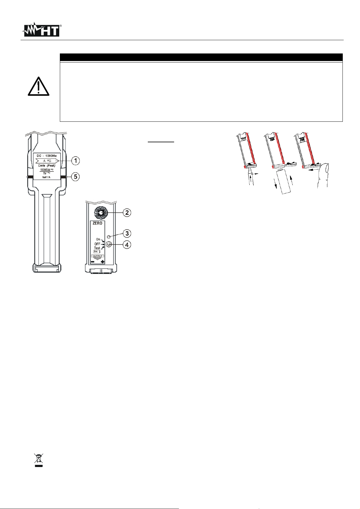
Freccia indicante il
verso di riferimento
Regolatore condizione
Selettore ON/OFF e
test di carica della
Per la sostituzione della batteria interna (per
batteria
Corrente primaria:
1000A AC/DC FS
Grado di inquinamento:
2 secondo IEC/EN61010-1
Campo di misura:
10A ÷ 1000A
Isolament o protett ivo:
Doppio isolam ento
Rapporto di uscita:
1000/1 1mV =1A
Categoria di installazione:
CAT III 600V
Incertezza:
±(10%let tur a + 2mV ) da 10 a 100A
±(1.5%lettura + 2mV) da 700 a 1000A
Alimentazione:
1 x 9V batt eria tipo 6LR61
Autonomia batteria:
circa 72 ore
Indice di Protezione:
IP20
Influenza del posizionamento
del cav o:
Campo di temperatura:
-5°C ÷ +50°C
Max diametro cavo (mm):
83 (barre 100x64 o 122x54)
Coefficiente di temperatura:
0.1% della lettura / °C
Dimensioni (mm):
336(L) x 137(La) x 42(H)
Impedenza di carico:
>10kΩ e <100pF
Peso:
Ca 1.8kg
Campo di frequenza:
DC ÷ 1000Hz
Collegamento in uscita:
Connettore Hypertac
ATTENZIONE: il simbolo riportato sullo strumento indica che l'apparecchiatura ed i suoi accessori devono essere
raccolti separat amente e tratt ati in modo corretto
Copyright HT IT ALI A 20 11 Versione 1.00 - 14/07/2011
MANUALE D’USO
pericolosa
• L'o pera tore deve ess ere comp let amente informat o su tut te l e necessar ie normative per la sicurezza
•
manuale
• Cor rent i di valo re el evato in prossim i tà del toroide posso no alt erare la m isu r a
• Al fine di massimizzare la precisione di lettura posizionare il conduttore sempre al centro del toroide
• Pri ma di utilizza re la pinza v er ificare sempre che la med esima s ia i ntegra e p erf et tamente funzionante
LEGENDA:
1.
della corrente
2.
di ZE RO
3. LED rosso indicatore
4.
batter ia i nter na
5. Limite della zona di
Fig. 2: Sostituzione batteria interna
sicurezza per
impugnare la pinza
tens ion e <6V) opera re com e segu e (ved ere Fig.
2):
1. Esercitare una lieve pressione sul piccolo
foro presente sul coperchio del vano batteria
utilizzando ad esempio la punta di un giravite
2. Traslare verso l’esterno il coperchio del vano
batteria
3. Estrarre la batteria scarica e sostituirla con
una dello stesso tipo rispettando la polarità
Fig. 1: D escrizione strumento
indicata sul manico della pinza
4. Richiudere a scatto il coperchio del vano
SPECIFICHE TECNICHE (temperatura amb iente 18°C ± 5°C e cavo centrato nel toroid e)
±(2%let tur a + 2mV ) da 100 a 700A
0,5% a 50Hz
PROCEDURA DI MISURA
1. Connettere il terminale di uscita della pinza allo strumento utilizzato per la visualizzazione
2. Mantenere premuto il selettore ON/OFF nella posizione “Test” per 10s e verificare l’accensione del LED rosso indicatore. Sostituire
la b at t er i a ( ved er e Fi g. 2) in caso di LED rosso spento. Nel caso in cui il led stia acceso per meno di 10s non sono garantite le 72
ore di funzionamento
3. Accendere la pinza spostando il selettore su “On”. Il LED ross o i ndic ator e deve esser e ac ceso . Verific are l’indicazione prossima
allo zero a display dello strumento usato per la visualizzazione. Agire eventualmente sul regolatore ZERO per azz era re il va lor e a
display prima di procedere con la mis ura
4. Aprire il toroide ed inserire il conduttore di cui si vuole misurare la corrente al centro dello stesso, rispettando la direzione della
corrente in misura (vedere Fig. 1)
5. Eseg uire l a l ett ura dell a corrente sullo st rumento uti lizzato per la visualizzazione. Spegnere la pinza dopo l’utilizzo
1
Page 2

ENGLISH HP30D1
SAFETY WARNING
• This note must be read in full. Any operations on live conductors can be dangerous
The operator is expected to be fully aware of all necessary electrical safety regulations and procedures. Safe
Strong vibrations and impacts may cause damage to the instru ment
INSTRUMENT DESCRIPTION
BATTERY REPLACEMENT
Arrow which shows the
current reference
ZERO adjustment
ON/OFF and battery
Indicate the limits of
safe area for handling
Consider the herewith steps to replace internal
top of battery cover by using e.g. a small
Prima ry rates cu rrent:
1000A AC/DC FS
Pollution degree:
2 com ply wi th IEC/EN61010-1
Measuring range:
10A ÷ 1000A
Insulation:
Double insulation
Output ratio:
1000/1 1mV =1A
Overvoltage category:
CAT III 600V
Accuracy:
±(10%rdg+ 2m V) from 10 to 100A
±(1.5%rdg + 2mV) from 700 to 1000A
Power supply:
1 x 9V battery type 6LR61
Battery life:
about 72 hours
Protection index::
IP20
Temper ature range:
-5°C ÷ +50°C
Max diamet er of cable (mm):
83 (bars 100x64 or 122x54)
Temper ature Co efficient:
0.1% of reading / 1°C
Dimensioni (mm):
336(L) x 137(La) x 42(H)
Load impedance:
>10kΩ e <100pF
Weight:
Ca 1.8kg
Frequency range:
DC ÷ 1000Hz
Output connector:
Hypertac connector
CAUTION: this symbol indicates that equipment and its accessories shall be subject to a separate
collection and cor r ec t disposal
Copyright HT IT ALI A 20 11 Release 1.00 - 14/07/2011
USER MANUAL
•
operation is this responsibility
• Never exceed the limit of voltage (600V) or current (1000A AC/DC) indicate in this manual
• When mea suring current, i f stron g current nears to the clamp j aw, i t will aff ect t he ac curacy
• While measuring current, always put the tested conductor in the center of c l amp ja w so a s to obt ain a more
accurate reading
• It is up to the user to ensure that the equipment is at all times in its original safe conditions
•
LEGEND:
1.
direction
2.
thumbwheel
3. Red LED i ndicator
4.
test selector
5.
Fig. 2: Battery replacement operation
the clamp
battery (for voltage <6V) (see Fig. 2):
1. Perf orm a li ttle pr essure o n the hol e on the
screwdriver
2. Shift a nd det ach the b at ter y cov er
3. Remove the battery and replace with a same
type new one considering the correct polarity
Fig. 1: I nstr ument des cription
which is shown on clamp handle
4. Replac e w it h a click the bat ter y cov er
TECHNICAL SPECIFICATIONS (ambient temperature 18°C ± 5°C and condutctor centered in the toru s)
±(2%rdg + 2mV) f rom 100 to 700A
Position cable sensitivity: 0,5% at 50Hz
MEASUREMENT PROCEDURE
1. Connect clamp’s output terminal to the inputs of the instrument to be used as indicator
2. Press and hold the ON/OFF selector on “Test” position for 10s and verify the red LED on. Replace the battery (see Fig. 2) if the
red LED is off. In the event that the LED is turned on for less than 10s are not guaranteed 72 hours of operation
3. Power on the met er by move the s elector on “On” position. The red LED should be fixed on. Verify the zero at display of
ins trument to be used as indicator . If no move ZERO regulation trimmer on clamp before start the measurement
4. Open the clamp and put the tested conductor in the center of the clamp jaws. No gap is allowed between the connections of
cl amp jaws. A lways co nsider t he cor rect conn ection of cl amp (s ee Fig. 1)
5. Read the current value in t he indicator’s display. Turn off the meter at th e end of mea surements
2
Page 3

SPANISH HP30D1
ATENCIÓN
• Esta nota debe ser leida en su totalidad. Cualquier operación sobre conductores con tensión puede ser
No utilice la pinza fuera de los límites de Tensión (600V) y corriente (1000A CA/CC) especificada en este
• Tirones violentos pueden d añar el instrumento
DESCRIPCIÓN DEL INSTRUMENTO
CAMBIO DE LA PILA
indicando el
Regulación condición
Selector ON/OFF y test
de carga de la pila
zona de
Para la sustitución de la pila interna (para
Efectúe una leve presión sobre el pequeño
agujero presente sobre la tapa de pilas
utilizando por ejemplo la punta de un
Extraiga la pila descargada y sustitúyala
con una del mismo tipo respetando la
4. Ponga de nuevo la tapa de pilas
Corriente primaria:
1000A AC/DC FS
Grado de polución:
2 segundos IEC/EN61010-1
Rango medida:
10A ÷ 1000A
Aislamiento:
Doble aislamiento
Relación:
1000/1 1mV =1A
Categorí a de sobret ensión:
CAT III 600V
Precisión:
±(10%lectura + 2mV) da 10 a 100A
±(1.5% lectura + 2m V) da 700 a 1000A
Alimentación:
1 x 9V pila tipo 6LR61
Dura ción de la batería
Ca 72 horas
Indi ce de p rot ección
IP20
Influencia del
posicionamiento del cable:
Rango de temperatura:
-5°C ÷ +50°C
Máx diámetro cable (mm):
83 (bares 100x64 o 122x54)
Coeficiente d e temp eratura:
0.1% lectura / 1°C
Dimensiones (mm):
336(L) x 137(La) x 42(H)
Carga externa:
>10kΩ e <100pF
Peso:
Ca 1.8kg
Rango de frecuencia:
DC ÷ 1000Hz
Conexión de salida:
Hyp ertac ter mi nal
ATENCIÓN: el símbolo incluido sobre el instrumento indica que el aparato y sus accesorios deben ser reciclados
separadamente y tratados de modo correcto
Copyright HT IT ALI A 20 11 Versión 1.00 - 14/07/2011
MANUAL DE INSTRUCCIONES
peligrosa
• El usuario debe estar completamente informado sobre todas las necesarias normativas para la seguridad
•
manual
• Cor r iente de valor el evad o cer ca del tor oidal puede alterar la medida
• Con el fin de maximizar la precisión de lectura posicione el conductor siempre en el centro del toroidal
• Antes de utilizar la pinza verifique que esté en buen estado
LEYENDA:
1. Flecha
sentido de la corriente
2.
ZERO
3. LED rojo indicador
4.
interna
Límite de la
5.
seguridad para
impugnar la pinza
Fig. 2: C ambi o de la pila
tensiones <6V) proceda como sigue (ver Fig.
2):
1.
destornillador
2. Desp lace la tapa de pilas
3.
Fig. 1: Descr ipc ión del i nstr umento
ESPECIFICACIONES TÉCNICAS (temperatura de 18 ° C ± 5 ° C y cable centrada en el toro)
±(2% lectura + 2mV) da 100 a 700A
0,5% a 50Hz
PROCEDIMIENTO DE MEDIDA
1. Conecte el terminal de salida de la pinza al instrumento utilizado para la visuali z aci ón
2. Mantenga pulsado el selector ON/OFF en la posición “Test” para 10s y verifique el encendido del LED rojo indicador. Sustituya
la pila (v er Fig. 2) en caso de LED rojo apagado. En el caso de que el LED se enciende por menos de 10 segundos no se
garantiza 72 horas de operación
3. Encienda la pinza con el selector en “On”. El LED rojo indicador debe estar encendido . Ver if iqu e l a ind ica ci ón pr óx ima al c ero
en el visualizador del instrumento. Gire eventualmente sobre el regulador ZERO para dejar a cero el valor antes de proceder
con la medidAbra el maxilar e coloque en el centro el conductor del cual se desea medir la corriente, respetando la dirección de
la corriente (ver Fig. 1)
4. Efectúe la l ectura d e la cor ri ente sobre el i nstrumento utilizado para l a v isualización
5. Apague la pinza después de su uso
polaridad indicada en el mango de la pinza
3
Page 4

DEUTSCH HP30D1
ACHTUNG
• Diese Anleitung und die enthaltenen Sicherheitshinweise sind zu lesen und zu befolgen
chen Sicherheitsbestimmungen bezogen auf das Schützen Ihrer selbst vor
gefährlichen elektrischen Strömen und Spannungen kennen und einhalten. Die sichere Benutzung liegt in
Bei der Strommessung beeinflussen starke Ströme, die nahe oder dicht an der Zange vorbeifließen, die
der Zangenöffnung, damit Sie
Es liegt in der Pflicht und Verantwortung des Anwenders, sicherzustellen, dass das Messgerät nur im
Starke Vibrationen und äußere Schlageinwirkungen können das Messgerät beschädigen
INSTRUMENTEN BESCHREIBUNG
BATTERIEWECHSEL
AN/AUS und Battery
Beachten Sie die hier angegebene
Drücken Sie leicht mit einem
her in das kleine Loch des
Schieben Sie den Batteriefachdeckels zur
Entfernen Sie die Batterie und ersetzen Sie
teriefachdeckel mit
einem Klick wieder in die richtige Position
Strombereich:
1000A AC/DC FS
Verschmutzungsgrad:
2 (IEC/EN61010-1)
Messbereich:
10A ÷ 1000A
Isolation:
Doppelte, verstärkte Isolation
Ausgangsverhältnis:
1000/1 1mV =1A
Überspannungskategorie:
CAT III 600V
Genauigkeit:
±(10%rdg + 2mV) 10A bis 100A
±(1.5%rdg + 2mV) 700A bis 1000A
Stromversorgung:
1 x 9V batterientyp 6LR61
Batterie Lebensdauer:
72 Stunden
Indice di Protezione:
IP20
Einfluss der Position der
Kabel:
Arbeitstemperatur:
-5°C ÷ +50°C
Max. Kabeldurchmesser (mm):
83 (bars 100x64 oder 122x54)
Temperaturkoeffizient:
± 0.1%anz /°C
Dimensionen (mm):
336(L) x 137(La) x 42(H)
Minimale Last:
>10kΩ e <100pF
Gewicht:
1.8kg
Frequenzbereich:
DC ÷ 1000Hz
Anschluss:
Hyp ertac Steck er
Achtung: Dieses Symbol zeigt an, dass das Gerät und die einzelnen Zubehörteile fachgemäß und getrennt
voneinander entsorgt werden müssen
Copyright HT IT ALI A 20 11 Ausführung 1.00 - 14/07/2011
BEDIENUNGSANLEITUNG
• Der Anwender muss die übli
sei ner V eran twortung
• Messen Sie keine Stromkreise, d ie die Spannungs- oder Stromgren zwerte d es St romwandlers von 6 00V bzw.
1000A AC/DC übersteigen
•
Messgenauigkeit
• Setz en Si e, wen n Sie Str om mes sen, d en gepr üft en Leit er imm er in s Zent rum
eine gena uer e Ablesung der Messwer te er halten
•
Originalzustand eing esetzt wird
•
LEGENDE:
1. Richtungspfeil der die
Stromflussrichtung
anzeigt
2. ZERO “Null” Justage
3. Roter L ED In dikator
4.
Test Wahlschalter
5. Geben S i e d i e G renz en
des sicheren Bereichs
Abb. 2: Batterieaustausch
für den Umgang mit der
Klemme
Vorgehensweise um die Batterie zu ersetzen.
(für Spannungen <6V) (siehe Abb.2):
1.
Schraubendre
Batteriefachdeckels
2.
Seite und ent fer nen Sie I hn
3.
diese durch eine Batterie gleichen Typs.
TECHNISCHE CHARAKTERIS TIK (Umgebungstemperatur 18 ° C ± 5 ° C und condutctor in den Torus zentriert)
Abb. 1:Instrumentenbeschreibung
Beac hten Si e die korrekte Polarität
4. Setzen Sie den Bat
±(2%rdg + 2mV) 100A bis 700A
0,5% 50Hz
MESSUNG DURCHFÜHREN
1. Verbinden Sie die Ausgangsmessleitungen der Stromzange mit den Eingängen des Messgerätes zur Messwer terfassun g
2. Stellen und halten Sie den ON/OFF Schalter in der Position “Test” für 10s und üb er p r üf en S i e, o b d i e ro t e L ED an i s t. Er set z en
Sie die Batterie wenn die rote LED aus ist (siehe Abb. 2). Für den Fall, dass die LED eingeschaltet ist für weniger als 10s
ausgeschaltet sind nicht 72 Stunden Betrieb gewährleistet
3. Stel len Sie d en O N/O FF Sc halt er i n di e Posi ti on “ON”. Die rote LED sollte leuchten. Überprüfen Sie, ob die Anzeige des mit
angeschlossenen Messgerätes den W ert “0“ anzeigt. Wenn nicht, st ellen Sie mit Hilf e des ZERO Trimmers den angezeigten
Wert auf „0“ bevor Sie die Messung starten
4. Öffnen Sie die Stromzangenbacken und legen Sie den zu überprüfenden Leiter in die Mitte der Zangenbacken. Die
Zangenbacken müssen komplett geschlossen sein. Der Richtungspfeil auf der Stromzange muss in die Stromflussrichtung
zeigen. ( siehe A bb. 1)
5. Lesen Sie den Stromwert vom Messgerät ab. Schalten Sie die Stromzange nach Beendigung der Messungen aus
4
 Loading...