

Page 1

ENGLISH
User manual
Copyright HT ITALIA 2012 Release EN .0 - 4//2012
Page 2

GEO416 - GEO416GS
Table of contents:
1. SAFETY PRECAUTIONS AND PROCEDURES .......................................................... 2
1.1. Preliminary instructions ..................................................................................................... 2
1.2. During use ......................................................................................................................... 3
1.3. After use ............................................................................................................................ 3
1.4. Definition of measurement category (Overvoltage) ........................................................... 3
2. GENERAL DESCRIPTION ........................................................................................... 4
2.1. Instrument description ....................................................................................................... 4
3. PREPARING THE INSTRUMENT ................................................................................ 4
3.1. Initial check........................................................................................................................ 4
3.2. Power supply ..................................................................................................................... 4
3.3. Calibration ......................................................................................................................... 4
3.4. Storage .............................................................................................................................. 4
4. WORKING INSTRUCTIONS ........................................................................................ 5
4.1. Instrument description ....................................................................................................... 5
4.2. MEASURING ACCESSORIES DESCRIPTION ................................................................ 5
Fig. 2: Measuring accessories description ................................................................................................ 5
4.2.1. Switching on ............................................................................................................................. 6
4.2.2. Auto power off .......................................................................................................................... 6
4.3. EARTH 3W – 3 wire earth resistance measurement ......................................................... 7
4.4. EARTH 2W – 2 wire earth resistance measurement ......................................................... 9
4.5. - Ground resistivity measurement ................................................................................ 12
4.5.1. Anomalous measuring applications ....................................................................................... 15
5. MANAGEMENT OF STORED DATA .......................................................................... 17
5.1. How to save a measurement ........................................................................................... 17
5.2. how to cancel one or several measurements .................................................................. 17
5.3. How to recall a measurement .......................................................................................... 18
6. INSTRUMENT RESET ............................................................................................... 19
7. INSTRUMENT CONNECTION TO PC ....................................................................... 19
8. MAINTENANCE ......................................................................................................... 20
8.1. General............................................................................................................................ 20
8.2. Battery replacement ........................................................................................................ 20
8.3. Instrument cleaning ......................................................................................................... 20
8.4. End of life ........................................................................................................................ 20
9. TECHNICAL SPECIFICATIONS ................................................................................ 21
9.1. Technical features ........................................................................................................... 21
9.1.1. Reference standards .............................................................................................................. 22
9.1.2. General features .................................................................................................................... 22
9.2. Environment .................................................................................................................... 22
9.2.1. Operating environmental conditions ...................................................................................... 22
9.3. Accessories ..................................................................................................................... 22
9.3.1. Standard and optional accessories GEO416 ......................................................................... 22
9.3.2. Standard accessories GEO416GS ........................................................................................ 22
10. SERVICE .................................................................................................................... 23
10.1. Warranty terms ................................................................................................................ 23
10.2. After-sales service ........................................................................................................... 23
11. PRACTICAL REPORTS FOR ELECTRICAL TESTS ................................................. 24
11.1. Earth resistance in tt systems ......................................................................................... 24
11.2. Earth resistance, voltaamperemetric method .................................................................. 25
11.2.1. Creating cables extensions .................................................................................................... 25
11.2.2. Method for small-sized earth rods.......................................................................................... 25
11.2.3. Method for large-sized earth rods .......................................................................................... 25
11.3. Ground resistivity ............................................................................................................. 26
11.3.1. Approximate evaluation of intentional rods' contribution ....................................................... 27
EN - 1
Page 3
GEO416 - GEO416GS
1. SAFETY PRECAUTIONS AND PROCEDURES
The instrument was designed in compliance with standards IEC/EN61557 and
IEC/EN61010-1 relative to electronic equipment.
CAUTION
For your own safety and to avoid damaging the instrument you are
recommended to follow the procedures described in this manual and read
carefully all instructions preceded by this symbol
Before and during measurements keep to the following instructions:
Do not take measurements in wet places as well as in the presence of explosive gas
and combustibles or in dusty places
Even though you are not taking any measurement avoid any contact with the circuit
under test, with exposed metal parts, unused measuring terminals, circuits etc
Do not take any measurement any measurement whenever anomalous conditions
occur such as deformations, breaks, leakages, blind display etc
Pay utmost attention when taking measurements of voltage higher than 25V in special
places (building yards, swimming pools, etc.) and higher than 50V in ordinary places
due to the risk of electric shock.
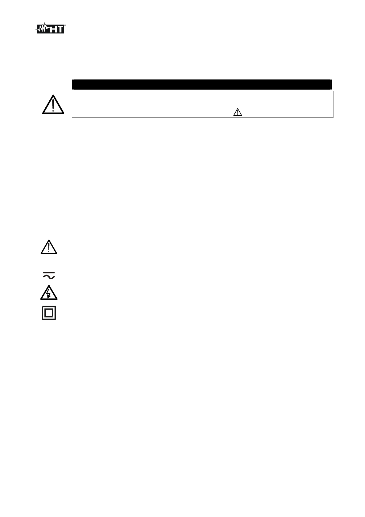
The following symbols are used in this manual as well as on the instrument:
CAUTION: Please read carefully this manual in order to understand the
nature of the potential danger and the actions to undertake
Refer to the instruction manual. An improper use may damage the instrument or
its components as well as endanger the user
DC or AC voltage and current
High voltage danger: risk of electric shock
Double insulation
1.1. PRELIMINARY INSTRUCTIONS
This instrument was designed for use in environments with pollution degree 2
It can be used for voltage and current measurements on electrical installations with
CAT III 240V to earth and maximum voltage of 415V between inputs
You are recommended to respect the usual safety regulations aimed at protecting you
against dangerous currents and the instrument against improper use
Only the original accessories supplied along with the instrument guarantee compliance
with the safety standards in force. They must be in a good condition and, if necessary,
replaced with identical ones
Do not test nor connect to any circuit exceeding the specified overload protection
Do not take measurements under environmental conditions exceeding the limits
indicated in this manual
Make sure that batteries are correctly installed
Before connecting test leads to the circuit under test check that the right function was
selected.
EN - 2
Page 4
GEO416 - GEO416GS
1.2. DURING USE
You are recommended to read carefully the following instructions:
CAUTION
Failure to comply with warnings and instructions may damage the instrument
and/or its components as well as injure the operator. If the low battery symbol
is displayed during use interrupt testing and replace batteries following the
procedure described in § 8.2
Before selecting a new function disconnect the test leads from the circuit under test
When the instrument is connected to the circuit under test never touch any unused
terminal
Do not measure resistance in the presence of external voltages; although the
instrument is protected, an excessive voltage may cause malfunction
Avoid submitting the instrument to voltage while measuring (i.e. a test lead slipping off
the measuring point accidentally touching an energized point).
1.3. AFTER USE
Turn off the instrument pressing ON/OFF key after using it
If you expect not to use the instrument for a long time remove the batteries.
1.4. DEFINITION OF MEASUREMENT CATEGORY (OVERVOLTAGE)
The standards IEC/EN61010-1: Safety requirements for electrical equipment for
measurement, control and laboratory use, Part 1: General requirements, define what a
measurement category, usually called over voltage category, means. Under § 6.7.4:
Measuring circuits, it quotes:
Circuits are divided into the following measurement categories:
Measurement category IV is for measurements performed at the source of a low-
voltage installation.
Examples are electricity meters and measurements on primary excess current
protection devices as well as ripple control units.
Measurement category III is for measurements performed in the building installations.
Examples are measurements on distribution boards, circuit breakers, wiring, including
cables, bus-bars, junction boxes, switches, socket-outlets in the fixed installations, and
equipment for industrial use as well as some other equipment, for example, stationary
motors with permanent connection to fixed installations.
Measurement category II is for measurements performed on circuits directly
connected to the low voltage installations.
Examples are measurements on household appliances, portable tools and similar
equipment.
Measurement category I is for measurements performed on circuits not directly
connected to MAINS.
Examples are measurements on circuits not derived from MAINS, and specially
(internally) protected MAINS-derived circuits. In this latter case, transient stresses are
variable; for this reason, the norm requires that the transient withstanding capability of
the equipment is made known to the user.
EN - 3
Page 5
GEO416 - GEO416GS
2. GENERAL DESCRIPTION
This instrument will grant you accurate and reliable measurements provided that is used
according to the instructions given in this manual. You will enjoy the highest safety thanks
to a development of newest conception assuring double insulation and over voltage
category III.
2.1. INSTRUMENT DESCRIPTION
EARTH 2W: 2-wire earth resistance measurement
EARTH 3W: 3-wire earth resistance measurement
ρ: 4-wire ground resistivity measurement.
3. PREPARING THE INSTRUMENT
3.1. INITIAL CHECK
This instrument was checked both mechanically and electrically prior to shipment. All
possible cares and precautions were taken to let you receive the instrument under perfect
conditions.
Notwithstanding we suggest you to check it rapidly to check any damage which may have
occurred during transport. Should it be the case please contact immediately the forwarder
or your dealer.
Make sure that all standard accessories mentioned in the enclosed packing list (see § 9.3)
are included in the packaging. In case of discrepancies contact your dealer. Should you
have to return back the instrument for any reason please follow the instructions mentioned
under § 10.
3.2. POWER SUPPLY
The instrument is powered by batteries (see § 9.1.2). The battery charge is displayed on
the right top side. The symbol indicates that batteries are fully charged, while the
symbol indicates that batteries are low and shall be replaced.
To replace/insert batteries follow the instructions indicated under § 8.2.
3.3. CALIBRATION
The instrument complies with the technical specifications reported in this manual and such
a compliance Is guaranteed for one year after purchase date.
3.4. STORAGE
After a period of storage under extreme environmental conditions exceeding the limits let
the instrument resume normal measuring conditions before using it (see § 9.2.1). This
precaution will grant accurate measurements without risking to damage the instrument.
EN - 4
Page 6

GEO416 - GEO416GS
4. WORKING INSTRUCTIONS
4.1. INSTRUMENT DESCRIPTION
CAPTION:
1. Inputs
2. ENTER/,,,keys
3. ESC/ key
4. RCL/CLR key
5. Display
6. GO key
7. SAVE key
8. ON/OFF key
Fig. 1: Instrument’s description
ENTER key to select measuring mode
Arrow keys to move the cursor selecting the required parameters
key to turn on the display backlight for 30 seconds
ESC key to quit without selecting any mode
RCL key to recall data stored in the instrument’s memory
CLR key to cancel the selected measurements from the instrument’s memory
GO key to start a measurement
SAVE key to store measurements
ON/OFF key to turn on/off the instrument
4.2. MEASURING ACCESSORIES DESCRIPTION
CAPTION:
1. Barrier
2. Hand-Held Area
Fig. 2: Measuring accessories description
EN - 5
Page 7
GEO416 - GEO416GS
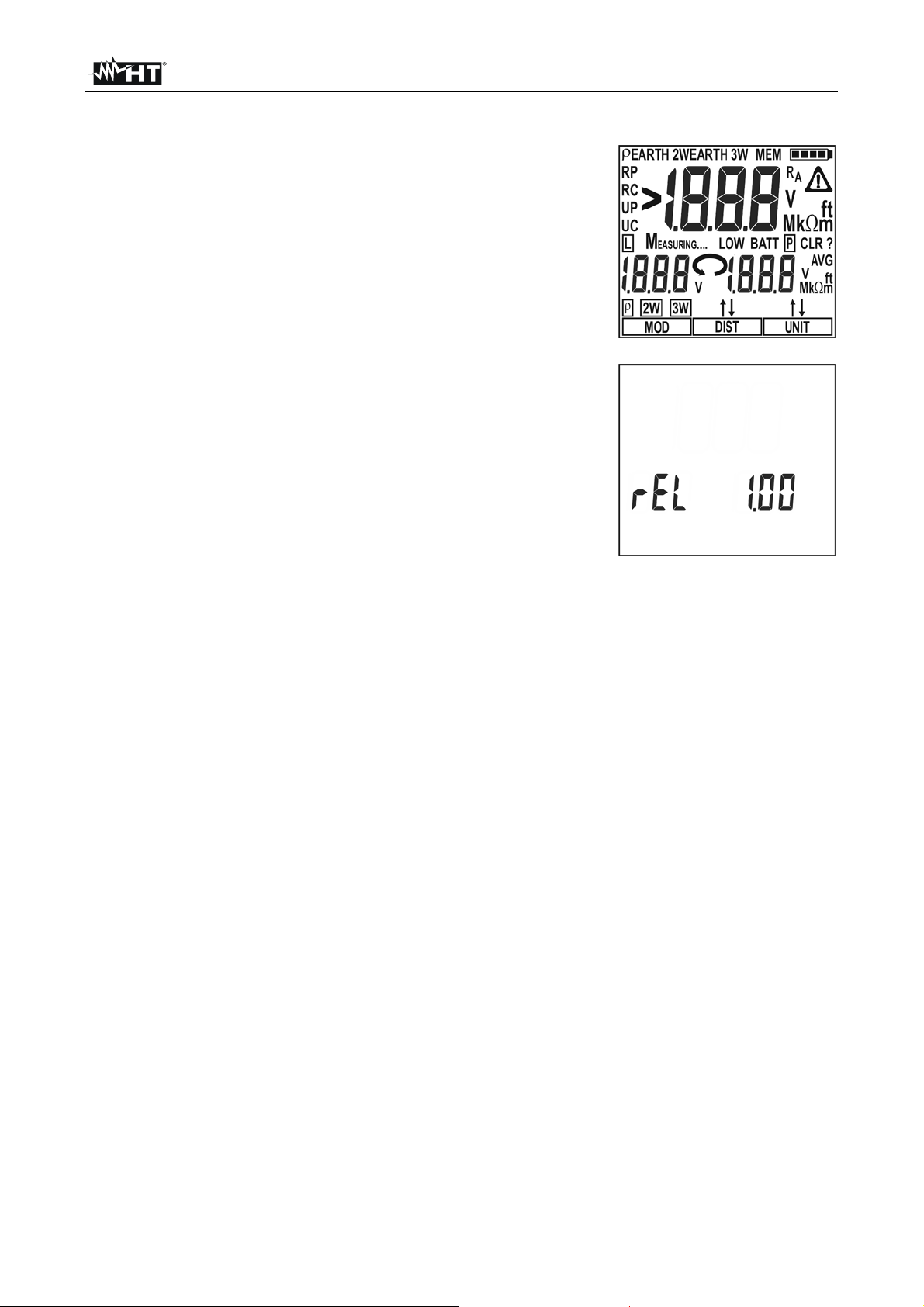
4.2.1. Switching on
When switching on the instrument a brief tone is audible along
with display of all segments for about one second.
Subsequently the last firmware version as well as the last
selected measuring mode are displayed before switching off.
4.2.2. Auto power off
The instrument automatically turns off 3 minutes after the last key pressing. To resume
operation turn on the instrument pressing the on/off key.
EN - 6
Page 8
GEO416 - GEO416GS
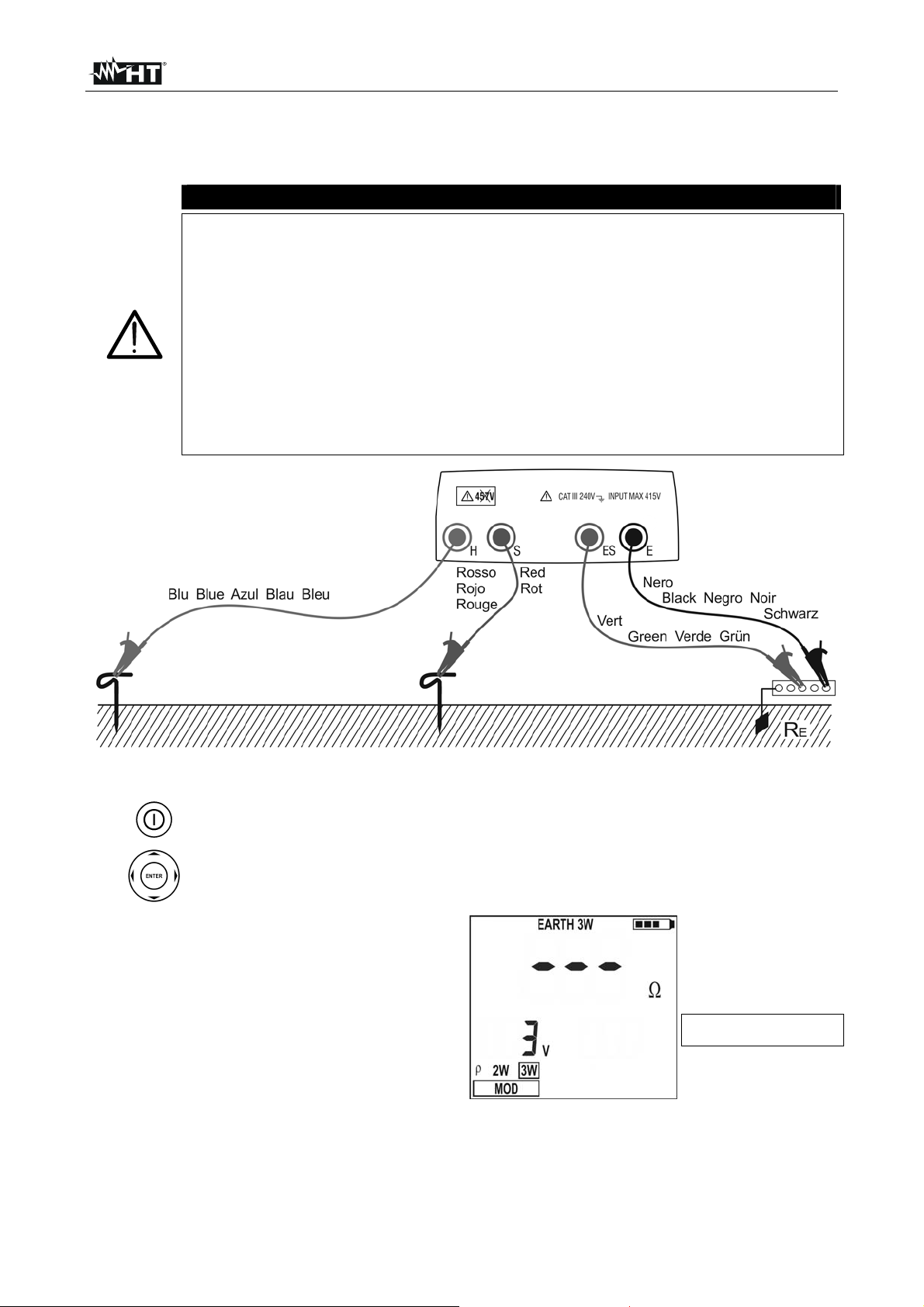
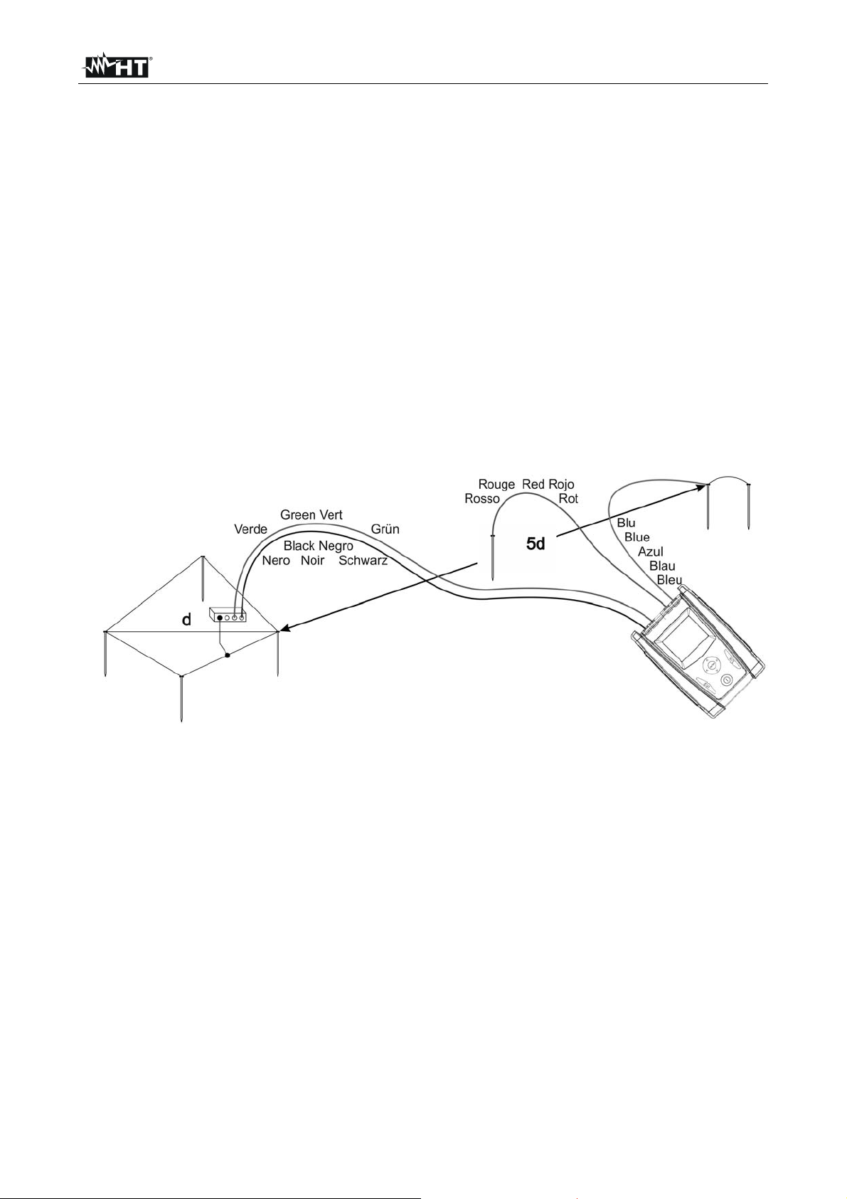
4.3. EARTH 3W – 3 WIRE EARTH RESISTANCE MEASUREMENT
The measurement is carried out in compliance with standards IEC 781, VDE 0413,
IEC/EN61557-5.
CAUTION
The instrument can be used for voltage and current measurements on
installations with over voltage category CAT III 240V to earth and maximum
voltage of 415V between inputs. Do not connect the instrument to
installations whose voltages exceed the limits indicated in this manual.
Exceeding such limits may cause electric shock to the user and damage
the instrument
Always connect the cables to the instrument and to the alligator clips when
the latter are not connected to the plant under test
Always respect the Hand-held area of probe (see § 4.2)
If the length of the supplied cables isn’t suitable for the plant under test (see
§ 11), You can create your own extensions following indications in § 11.2.1
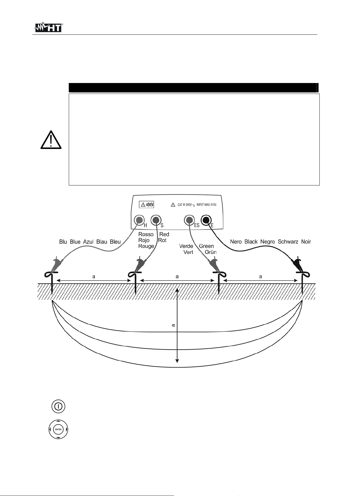
Fig. 3: Three-wire earth resistance measurement
1.
2.
Turn on the instrument pressing the ON/OFF key
Pressing right/left arrow keys , select MOD, then pressing up/down arrow
keys , select 3W option
3. A screen similar to the one beside
appears where the input interfering
voltage value of the instrument is
displayed
Input interfering voltage
value
4. Connect the blue, red, green and black cables to the corresponding instrument’s input
terminals H, S, ES, E then adding crocodiles if necessary
EN - 7
Page 9
GEO416 - GEO416GS
g
5. Extend, if necessary, the blue and red measuring cables separately using cables with
proper section. Adding any extension does not require calibration and does not affect
the measured earth resistance value
Drive the auxiliary rods into the ground keeping to the distance instructions provided
6.
by the standards (§ 11.2)
7. Connect crocodiles to the auxiliary rods and to the installation under test (see Fig. 3)
8.
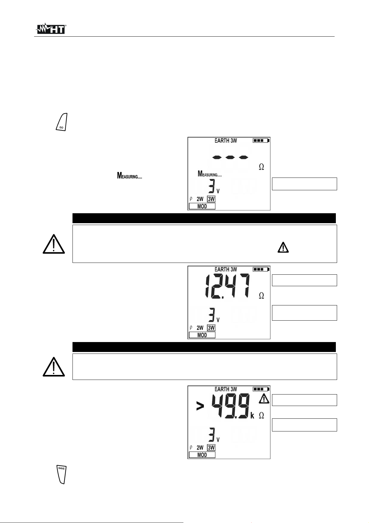
Press GO key, the instrument starts carrying out measurement
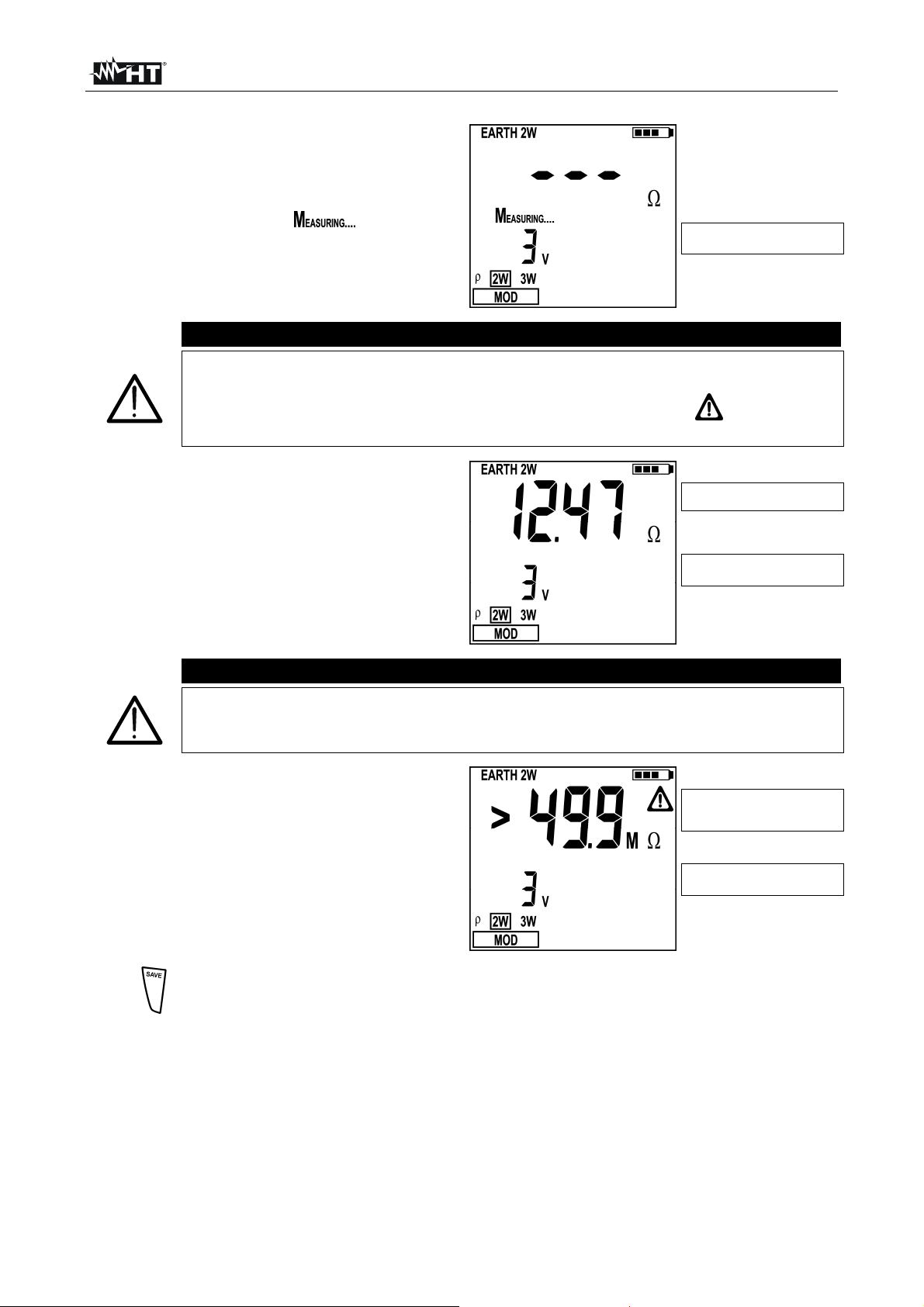
9. While the instrument is measuring a
screen similar to the one beside
appears where the instrument’s input
interfering voltage value is displayed.
When the message is displayed
do not disconnect or touch the test
leads
CAUTION
When starting measurement the input interfering voltage is measured at both
the volt and ampere circuit. Should it range between 3 V and 9 V, the
instrument carries out measurement and displays the symbol indicating the
uncertainty decline of the measurement (§ 9.1)
10. When the test is over, should the earth
resistance value be lower than the full
scale, the instrument emits a double
tone indicating the positive outcome of
the test and displays the resistance
measurement as well as the interfering
voltage value at the time of measuring
CAUTION
The resistance measurement is effected with 4-wire volt ampere method
without being affected by the resistance value of the cables. It is therefore not
necessary to effect compensation of cable resistance or of any extension
11. When the test is over, should the earth
resistance value be higher than the full
scale, the instrument emits a long tone
indicating the negative outcome of the
test and displays the screen beside
Input interfering voltage
value
Earth resistance
measurement
Input interfering voltage
value
Earth resistance value
her than full scale
hi
Input interfering voltage
value
12.
The measurements can be stored pressing the SAVE key twice (§ 5.1)
EN - 8
Page 10
GEO416 - GEO416GS
4.4. EARTH 2W – 2 WIRE EARTH RESISTANCE MEASUREMENT
CAUTION
The instrument can be used for voltage and current measurements on
installations with over voltage category equal to CAT III 240V to earth and
maximum voltage of 415V between inputs. Do not connect the instrument
to installations whose voltages exceed the limits indicated in this manual.
Exceeding such limits may cause electric shock to the user and damage
the instrument
Always connect the cables to the instrument and to the alligator clips when
the latter are not connected to the plant under test
Always respect the Hand-held area of probe (see § 4.2)
If the length of the supplied cables isn’t suitable for the plant under test (see
§ 11), You can create your own extensions following indications in § 11.2.1
Whenever it is not possible to drive rods into the ground to take a three-wire measurement
(i.e. historical centres), it is possible to use the simplified two-wire method which gives an
excess value for the sake of safety. To carry out the test a suitable auxiliary rod is
necessary; an auxiliary rod is deemed as suitable when its earth resistance is negligible
and independent of the earth installation under test.
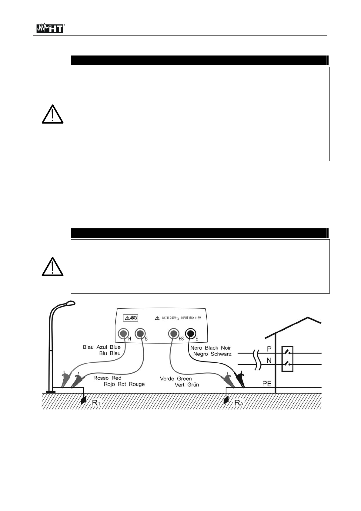
In Fig. 4 a lamp post is used as auxiliary rod, however any metal body driven into the
ground can be used provided that the above mentioned requirements are met.
CAUTION
The instrument displays the sum value of RA+RT as result (see Fig. 4 and Fig.
5). Therefore the measurement achieved is the closer to RA (prospective
value) the more negligible is the value RT of the auxiliary rod with respect to
RA itself. In addition the measurement will be increased “for safety sake” by
RT, i.e. if RA+RT results to be coordinated with protective conductors, RA alone
will be far more coordinated
Fig. 4: Two-wire earth resistance measurement using an auxiliary rod
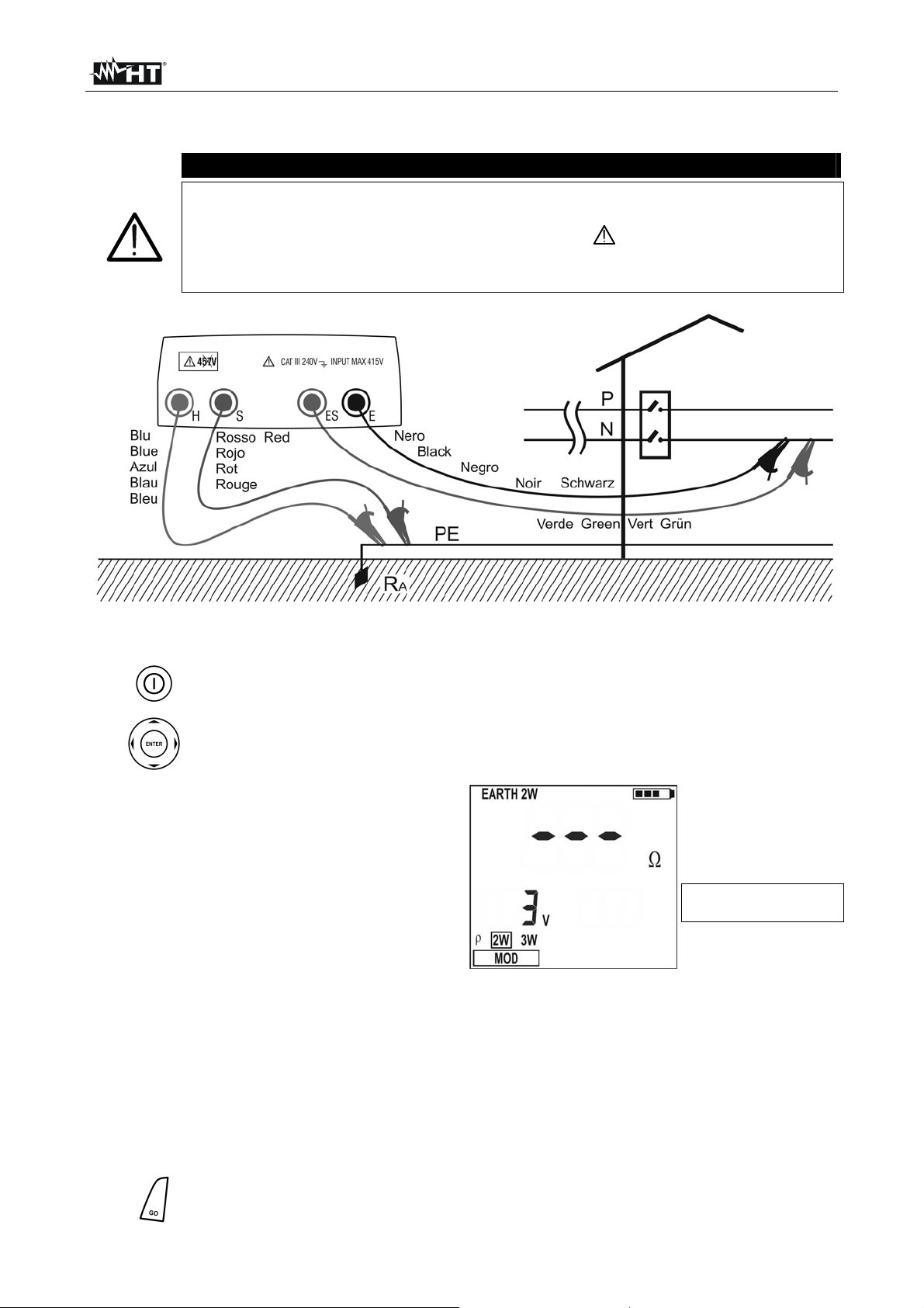
In the TT systems (see Fig. 5) it is possible to perform a two-wire earth measurement
using the NEUTRAL conductor provided by the national Energy Board taken directly from
a socket or panel board as an auxiliary rod; if also the earth connection is available, the
measurement can be taken on the socket directly, between NEUTRAL and EARTH.
EN - 9
Page 11
GEO416 - GEO416GS
CAUTION
If you wish to effect the measurement using the neutral and earth conductors
of an ordinary socket, you may accidentally connect to phase; in this case the
detected voltage as well as the warning symbol for wrong entering will be
displayed and no measurement will be effected even though the GO key is
pressed
Fig. 5: Two-wire earth resistance measurement from the panel board
1.
2.
Turn the instrument on pressing the ON/OFF key
Pressing the right and left arrow keys , select MOD, then pressing the up
and down arrow keys , select 2W option
3. A screen similar to the one beside
appears where the input interfering
voltage value of the instrument is
displayed
Input interfering voltage
value
4. Connect the blue, red, green and black cables to the corresponding instrument’s input
terminals H, S, ES, E then adding crocodiles if necessary
5. Extend, if necessary, the blue and red measuring cables separately using cables with
proper section. Adding any extension does not require calibration and does not affect
the measured earth resistance value
Connect crocodiles to the auxiliary rods and to the installation under test (see Fig. 4
6.
and Fig. 5)
7.
Press GO key, the instrument starts carrying out measurement
EN - 10
Page 12
GEO416 - GEO416GS
8. While the instrument is measuring a
screen similar to the one beside
appears where the instrument’s input
interfering voltage value is displayed.
When the message
do not disconnect or touch the test
is displayed
leads
CAUTION
When starting measurement the input interfering voltage is measured at both
the volt and ampere circuit. Should it range between 3 V and 9 V, the
Input interfering voltage
value
instrument carries out measurement and displays the symbol
uncertainty decline of the measurement (§ 9.1)
9. When the test is over, should the earth
resistance value be lower than the full
scale, the instrument emits a double
tone indicating the positive outcome of
the test and displays the resistance
measurement as well as the interfering
voltage value at the time of measuring
CAUTION
The resistance measurement is effected with 4-wire volt ampere method
without being affected by the resistance value of the cables. It is therefore not
necessary to effect compensation of cable resistance or of any extension
10. When the test is over, should the earth
resistance value be higher than the full
scale, the instrument emits a long tone
indicating the negative outcome of the
test and displays the screen beside
indicating the
Earth resistance
measurement
Input interfering voltage
value
Earth resistance
measurement higher than
full scale
Input interfering voltage
value
11.
The measurements can be stored pressing the SAVE key twice (§ 5.1)
EN - 11
Page 13
GEO416 - GEO416GS
A
4.5. - GROUND RESISTIVITY MEASUREMENT
The ground resistivity value is an essential parameter to calculate the resistance value of
the earth rods to be used for the earth installation’s construction. The measurement is
effected according to standards IEC 781, VDE 0413, IEC/EN61557-5.
CAUTION
The instrument can be used for voltage and current measurements on
installations with over voltage category equal to CAT III 240V to earth and
maximum voltage of 415V between inputs. Do not connect the instrument
to installations whose voltages exceed the limits indicated in this manual.
Exceeding such limits may cause electric shock to the user and damage
the instrument
lways connect the cables to the instrument and to the alligator clips when
the latter are not connected to the plant under test
Always respect the Hand-held area of probe (see § 4.2)
If the length of the supplied cables isn’t suitable for the plant under test (see
§ 11), You can create your own extensions following indications in § 11.2.1
1.
2.
Turn on the instrument pressing the ON/OFF key
Pressing right/left arrow keys , select MOD, then pressing up/down arrow
keys , select option
Fig. 6: Ground resistivity measurement
EN - 12
Page 14
GEO416 - GEO416GS
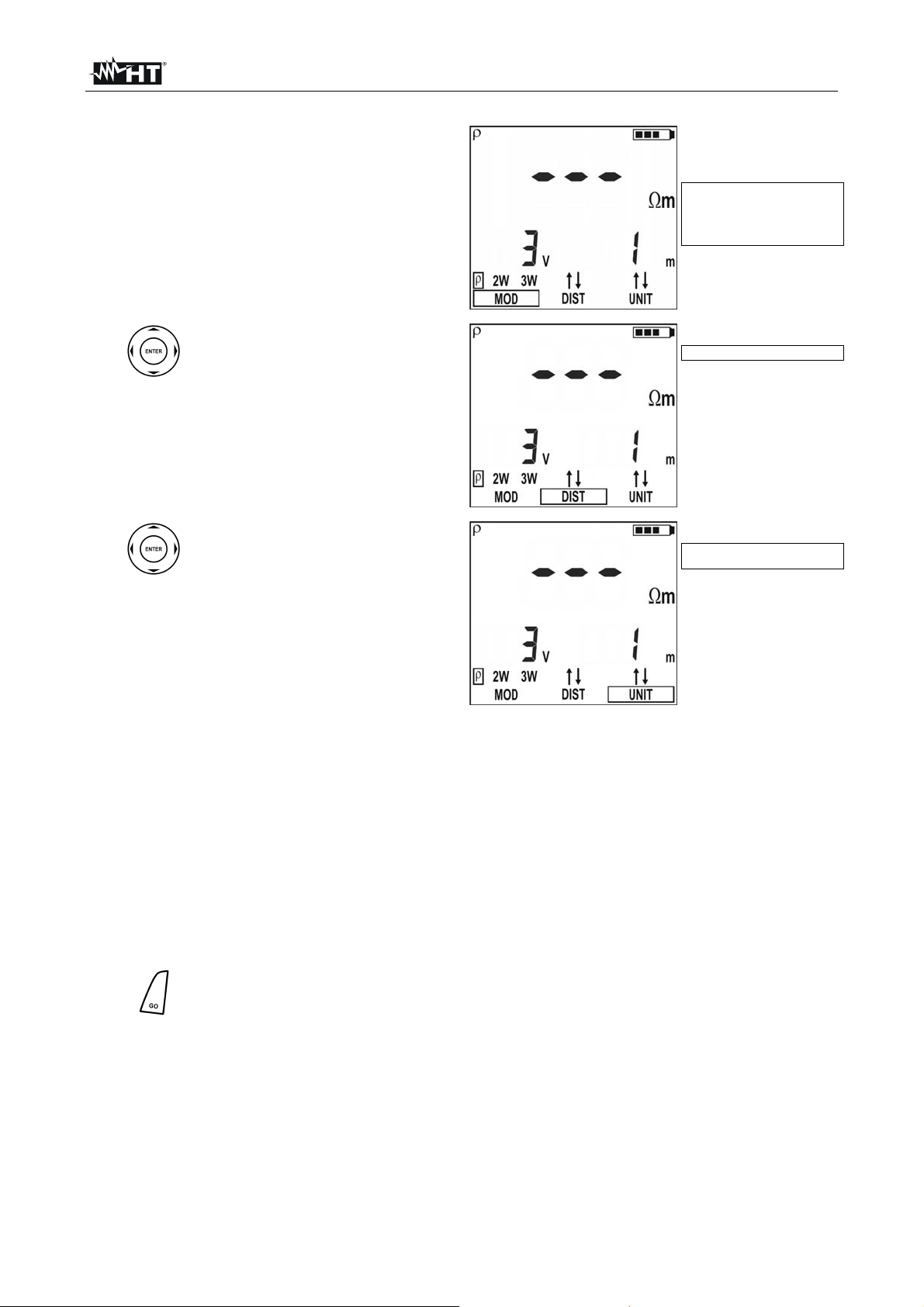
3. A screen similar to the one beside
appears where both the input interfering
voltage of the instrument and the rods’
distance value are displayed
Value of input interfering
voltage and rods' distance
set
4.
Should you need to modify the
rods’ distance press the arrow
keys , and select DIST,
then pressing the arrow keys
, set the desired distance
(ranging from 1 up to 10 metres,
by steps of one or from 3 up to
Value of rods' distance set
30 feet by steps of three)
To set the distance measuring
5.
unit press the arrow keys ,
and select UNIT, then pressing
the arrow keys , set the
desired measuring unit (m or ft)
Measuring unit selected
6. Connect the blue, red, green and black cables to the corresponding instrument’s input
terminals H, S, ES, E then adding crocodiles if necessary
7. Extend, if necessary, the blue and red measuring cables separately using cables with
proper section. Adding any extension does not require calibration and does not affect
the measured ground resistivity value
8. Drive the auxiliary rods into the ground placing them on a line at a mutual distance
equal to that selected on the instrument. Setting a distance other than the actual
distance between the earth rods may affect the measurement (§11.3)
Connect crocodiles to the auxiliary rods (see Fig. 6)
9.
10.
Press GO key, the instrument starts carrying out measurement
EN - 13
Page 15
GEO416 - GEO416GS
y
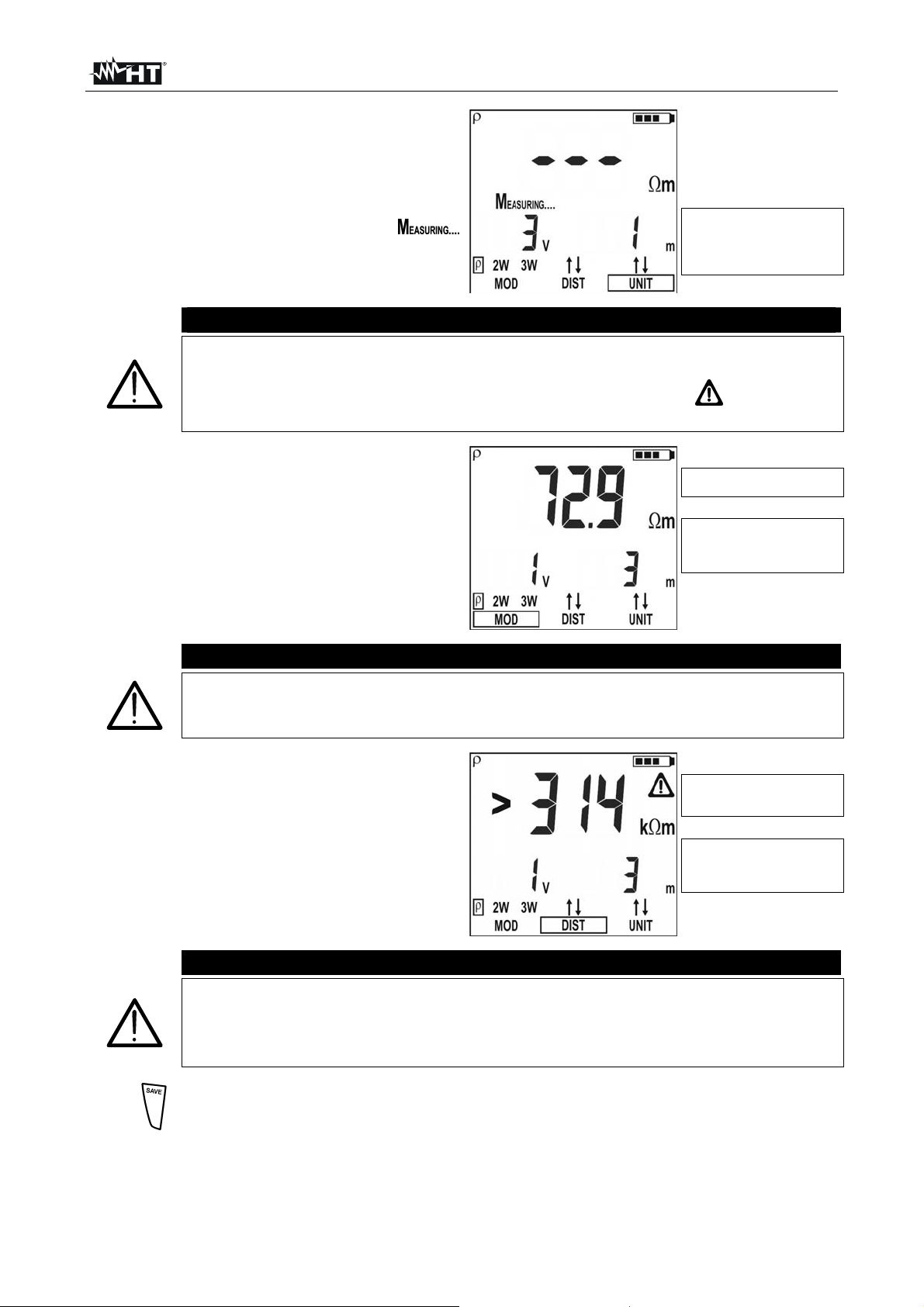
11. While the instrument is measuring a
screen similar to the one beside
appears where the instrument’s input
interfering voltage value and the
distance set between auxiliary rods are
displayed. When the message
is displayed do not disconnect or touch
the test leads
CAUTION
When starting measurement the input interfering voltage is measured at both
the volt and ampere circuit. Should it range between 3 V and 9 V, the
Value of input interfering
voltage and rods' distance
set
instrument carries out measurement and displays the symbol
uncertainty decline of the measurement (§ 9.1
12. When the test is over, should the
ground resistivity value be lower than
the full scale, the instrument emits a
double tone indicating the positive
outcome of the test and displays the
resistivity measurement as well as the
interfering voltage value at the time of
measuring
CAUTION
The resistivity measurement is effected with 4-wire volt ampere method without
being affected by the resistance value of the cables. It is therefore not
necessary to effect compensation of cable resistance or of any extension.
13. When the test is over, should the
ground resistivity value be higher than
the full scale, the instrument emits a
long tone indicating the negative
outcome of the test and displays the
screen beside
indicating the
Measurement of ground
resistivit
Value of input interfering
voltage and rods' distance
set
Measurement of ground
resistivity higher than the
full scale
Value of input interfering
voltage and rods' distance
set
CAUTION
The full scale is calculated as ρ
= 2 DIST R where DIST is the value set
MAX
for the distance among the rods and R the maximum resistance value which
can be measured by the instrument. The full scale of ground resistivity
measurement depends on the setting of the distance among the rods
14.
The measurements can be stored pressing the SAVE key twice (§ 5.1)
EN - 14
Page 16
GEO416 - GEO416GS
g
g
g
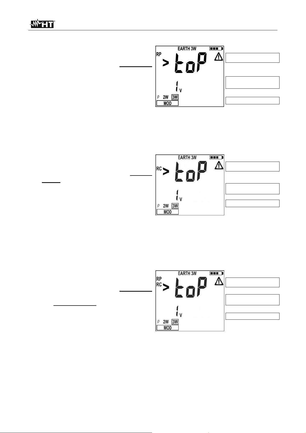
4.5.1. Anomalous measuring applications
1. When starting a measurement the
instrument checks the continuity of
measuring cables. If the volt circuit
(red cable S and green cable ES) is
interrupted or its resistance value is
too high, the instrument displays a
screen similar to the one beside. Check
that terminals are properly connected
and that the earth rod is connected to
Volt circuit’s resistance too
h
hi
Value of input interfering
voltage
Example for 3W mode
terminal S and not driven into a pebbly or scarcely conductive ground. In this latter
case pour water around the rod to decrease its resistance value (§ 11.2).
RP>top is displayed when:
The S rod’s resistance RS > 50KΩ is summed up to the volt circuit
2. When starting a measurement the
The resistance of rod S exceeds the value 1200 + 100 RX [Ω] (where RX is the
earth resistance value)
instrument checks the continuity of
measuring cables. If the ampere
circuit (blue cable H and black cable
E) is interrupted or its resistance
value is too high, the instrument
displays a screen similar to the one
Ampere circuit’s resistance
h
too hi
Value of input interfering
voltage
Example for 3W mode
beside. Check that terminals are
properly connected and that the earth
rod is connected to
terminal H and not driven into a pebbly or scarcely conductive ground. In this latter
case pour water around the rod to decrease its resistance value (§ 11.2).
RC>top is displayed when:
The H rod’s resistance RH > 50KΩ is summed up to the ampere circuit
The resistance of rod H exceeds the value 1200 + 100 R
earth resistance value)
3. When starting a measurement the
instrument checks the continuity of
measuring cables. If the volt circuit
(red cable S and green cable ES) and
the ampere circuit (blue cable H and
black cable E) are both interrupted or
their resistance values are too high,
the instrument displays a screen similar
to the one beside. Check that the
X [Ω] (where RX is the
Both volt and ampere
circuits’ resistance too hi
Value of input interfering
voltage
Example for 3W mode
terminals are properly connected and that the earth rods connected to terminals S
and H are not driven into a pebbly or scarcely conductive ground. In this latter case
pour water around the rods to decrease their resistance value (§ 11.2).
RP, RC>top is displayed when:
The S rod’s resistance RS > 50KΩ is summed up to the volt circuit and the H
rod’s resistance H R
Both the S rod’s resistance and the H rod’s resistance exceed the value 1200 +
H > 50KΩ is summed up to the ampere circuit
100 RX [Ω] (where RX is the earth resistance value)
h
EN - 15
Page 17
GEO416 - GEO416GS
g
g
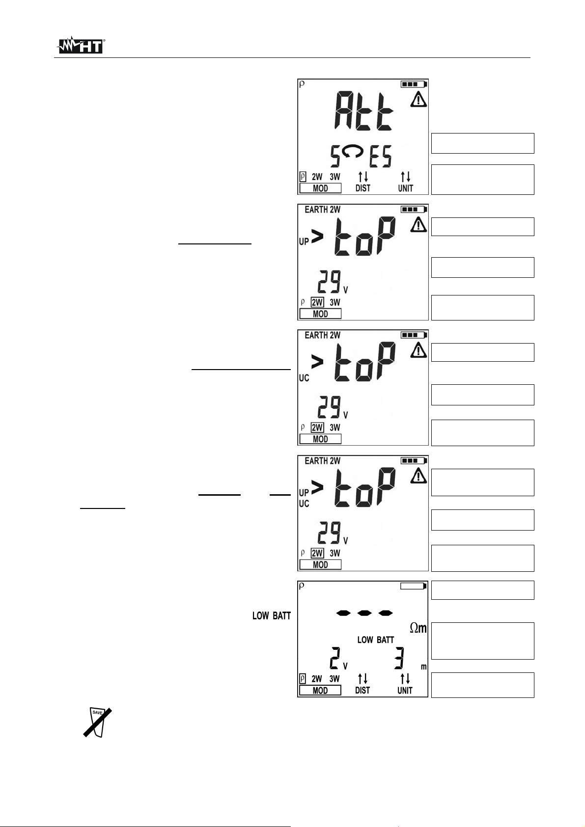
4. When starting a measurement, if the
red cable (connected to S terminal)
and the green cable (connected to ES
terminal) are reversed, the instrument
do not perform the test, emits a long
sound tone and displays the screen
beside
5. When starting a measurement, if an
interfering voltage higher than 9V is
detected at the volt circuit’s input,
the instrument do not perform the test,
emits a long sound tone and displays
the screen beside
6. When starting a measurement, if an
interfering voltage higher than 9V is
detected at the ampere circuit’s
input, the instrument do not perform the
test, emits a long sound tone and
displays the screen beside
Red and green cables
reversed
Example under ρ mode
Too high input interfering
e at volt circuit
volta
Input interfering voltage
value
Example under 2W mode
Too high input interfering
e at ampere circuit
volta
Input interfering voltage
value
7. When starting a measurement, if an
interfering voltage higher than 9V is
detected at both the ampere and volt
circuits’ inputs, the instrument do not
perform the test, emits a long sound
tone and displays the screen beside
8. If battery voltage is too low the
instrument displays the symbol of low
battery as well as the message
and no measurement is allowed. It is
however possible to carry out settings,
reading of stored data, etc
9.
The above said anomalous cases cannot be stored
Example under 2W mode
Too high input interfering
voltage at both ampere
and volt circuits
Input interfering voltage
value
Example under 2W mode
Too low power supply, low
batteries
Input interfering voltage
value and distance set
among rods
Example under ρ mode
EN - 16
Page 18
GEO416 - GEO416GS
p
p
p
5. MANAGEMENT OF STORED DATA
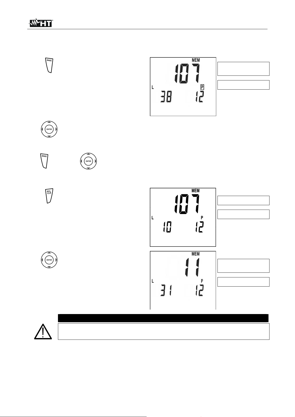
5.1. HOW TO SAVE A MEASUREMENT
1.
After taking a measurement
press SAVE key, the instrument
displays a screen similar to the
one beside
No. of memory location
where the measurement
has to be saved
Last value set for
arameters L and P
Should you need to modify the values of the parameters L and P press the
2.
3.
arrow keys , and select L or P, then pressing the arrow keys , set
the desired value (from 1 to 255). These values can enable you to trace back
the place where the measurement was effected
OR
Confirm measurement storing pressing SAVE key or ENTER
key
5.2. HOW TO CANCEL ONE OR SEVERAL MEASUREMENTS
Press RCL key, the instrument
1.
displays a screen similar to the
one beside
Number of the last memory
location used
Values of L and P
arameters
Press the arrow keys , to
2.
select the memory location
where cancellation of data is to
be started , the displays a
screen similar to the one beside
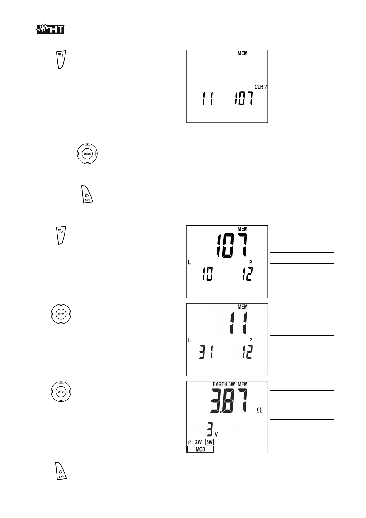
CAUTION
Confirming cancellation of data causes removal of all stored data starting from
the selected location till the last memory location
Number of the memory
location where cancellation
is to be started
Values of L and P
arameters
EN - 17
Page 19
GEO416 - GEO416GS
q
p
play
p
Press the CLR key, the
3.
instrument displays a screen
similar to the one beside
First and last memory
location to be cancelled
and confirmation re
uired
Alternatively:
Confirm cancellation of measurements pressing ENTER key, the
Or:
4.
4.
instrument emits a double sound tone confirming cancellation of the
selected measurements
Press ESC key to go back to previous screen
5.3. HOW TO RECALL A MEASUREMENT
Press the RCL key, the
1.
instrument displays a screen
similar to the one beside
Number of the last memory
location
Values of L and P
arameters
Press the arrow keys , to
2.
select the memory location
whose content is to be
displayed
Press the ENTER key to display
3.
the measurement stored inside
the selected memory location,
the instrument displays a
screen similar to the one beside
Press the ESC key to go back to previous screen and press the ESC key
4.
again to exit the memory management
Number of the memory
location whose content is
to be dis
Values of L and P
arameters
Measurement stored in the
selected memory location
Values of interfering
voltage at measurement
ed
EN - 18
Page 20
GEO416 - GEO416GS
3
6. INSTRUMENT RESET
CAUTION
BEFORE CARRYING OUT THE INSTRUMENT’S RESET SAVE ALL DATA
RELATIVE TO THE MEASUREMENTS EFFECTED BY DOWNLOADING
THEM TO A PC
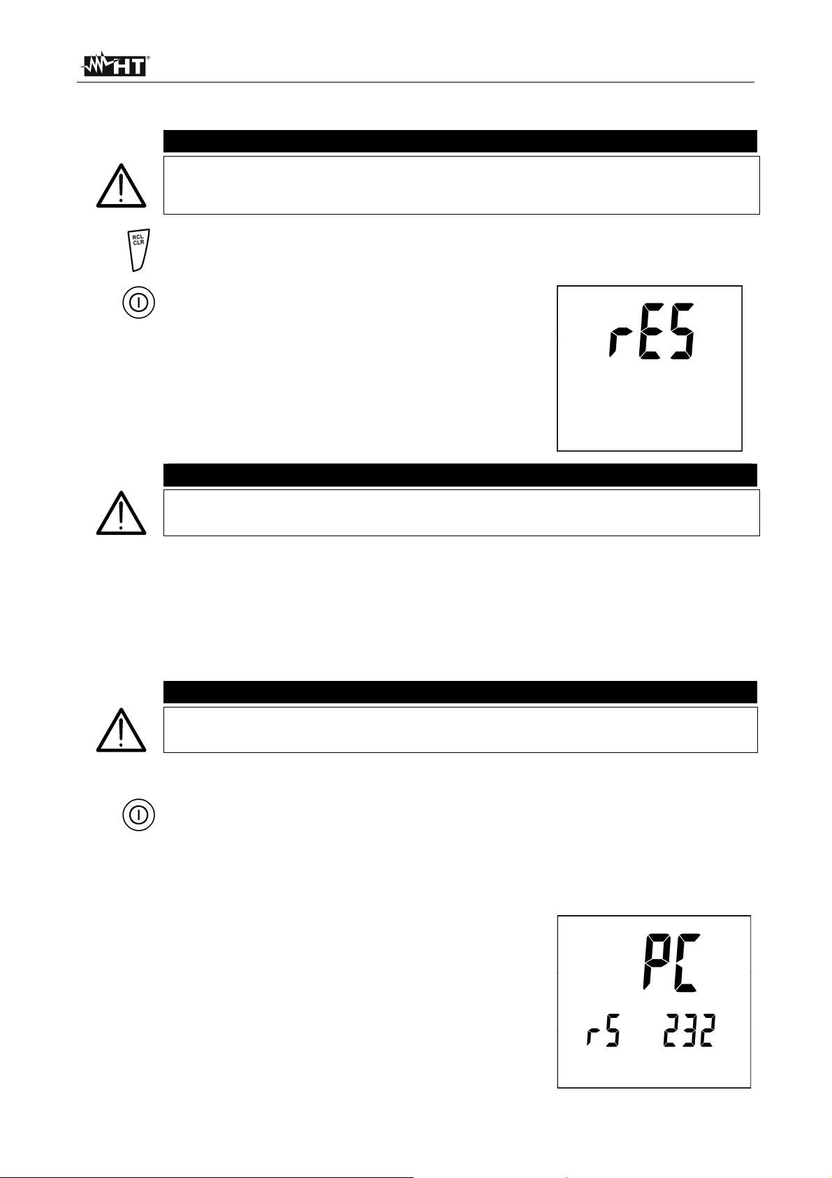
1.
2.
When the instrument is off press the RCL/CLR key
Keeping down the RCL/CLR key, press the switch
on key. The instrument emits a short sound tone
showing all display segments for approx. 1
second. Then it emits a second short sound tone
CAUTION
displaying the screen beside for approx. 3
seconds
The HARD RESET procedure deletes all data previously stored and the
parameter DST resumes its default value (1 m or 3 ft)
7. INSTRUMENT CONNECTION TO PC
The instrument can be connected to a PC by means of the serial port or USB and opt
insulated cable provided along with the software package. First it’s necessary to select the
COM port used for the transmission and the correct baud rate (9600 bps). To set these
parameters install the software and consult the help on line.
The selected port shall be free of any other device or application such as mouse, modem, etc.
CAUTION
Optical port emits Laser radiations , Don’t locate beam at eye level. Class 1M
laser apparatus according to EN 60825-1
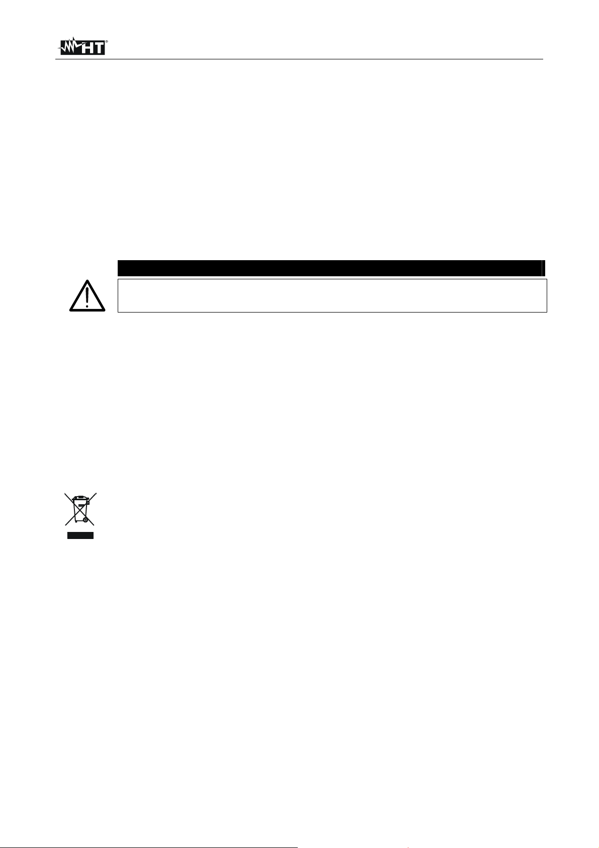
To transfer stored data to PC keep to the following procedure:
1.
Turn on the instrument pressing the power key
Connect the instrument to a PC by means of the opt insulated cable provided with the
software package. Communication is enabled at any function except for
2.
measurements as well as when memory management is active (§ 5)
. Use the data management software to download the
instrument’s stored data to a PC. During the data transfer
the instrument displays a screen as beside, then after
completing the data transfer goes back to the previously
selected mode
EN - 19
Page 21
GEO416 - GEO416GS
8. MAINTENANCE
8.1. GENERAL
This is a precision instrument. Strictly follow the instructions for use and storage reported
in this manual to avoid any possible damage or danger during use.
Do not use this tester under unfavorable conditions of high temperature or humidity. Do
not expose to direct sunlight.
Be sure to turn off the tester after use. If the instrument is not to be used for a long period
you are recommended to remove batteries to avoid leakages of battery liquid which may
damage its internal circuits.
8.2. BATTERY REPLACEMENT
When the low battery indication (see § 9.1.2) is displayed the batteries are to be replaced.
CAUTION
Only skilled technicians can open the instrument and replace batteries. Before
removing batteries disconnect all cables from input terminals
1. Turn off the instrument pressing the ON/OFF key for a while
2. Disconnect the cables from the input terminals
3. Remove the battery cover screws and detach the battery cover
4. Replace batteries with new ones of the same type (see § 9.1.2) keeping to the right
polarity signs
5. Replace cover and screws
6. Use the appropriate battery disposal methods for your area
8.3. INSTRUMENT CLEANING
Use a soft dry cloth to clean the instrument. Do not use wet clothes, solvents, water etc.
8.4. END OF LIFE
Caution: this symbol indicates that equipment and its accessories shall be
subject to a separate collection and correct disposal.
EN - 20
Page 22
GEO416 - GEO416GS
9. TECHNICAL SPECIFICATIONS
9.1. TECHNICAL FEATURES
Accuracy indicated as [%reading + (number dgts * resolution)] at 23 ± 5°C, <80%RH
3- and 2-wire earth resistance measurement - EARTH 3W and EARTH 2W
Measurement range (**)
Reading [] Measure []
0.01 19.99 0.08 19.99
20.0 199.9 20.0 199.9
200 1999 200 1999
2.00 19.99k 2.00 19.99k
20.0 49.9k 20.0 49.9k
Resolution []
0.01
0.1
1
0.01k
0.1k
Ground resistivity measurement - (distance among the rods=1m)
Range (**)
Reading [m] Measure m]
0.06 19.99 0.50 19.99
20.0 199.9 20.0 199.9
200 1999 200 1999
2.00 19.99k 2.00 19.99k
20.0 199.9k 20.0 199.9k
200 314k 200 314k
Measuring frequency: 77.5Hz; Test current: 12mA; Open loop voltage: < 25Vrms
Disturbance voltage on ampere and volt circuits: the measurement is taken with the stated accuracy if the interfering
voltage is 3V, while for interfering voltages ranging from > 3V and 9V, the accuracy decreases progressively;
with an interfering voltage equal to 9V the instrument does not perform the test
(*) If RP > 1200 + 100 RX and/or RC > 1200 + 100 RX, RP > 50k and/or RC > 50k and the instrument carries out the
test, the accuracy of the instrument is (10% reading) where:
RP = resistance of the voltage circuit; RC = resistance of the current circuit; RE = measured earth resistance
(**) Automatic selection of the range
Interfering voltage measurement
Range (**)
Reading [V] Measure [V]
0 460 7 460
(**) Automatic selection of the range
Resolution [m]
0.01
0.1
1
0.01k
0.1k
1k
Resolution [V] Uncertainty
1
Accuracy (*)
(2.5%rdg + 2dgt)
Accuracy (*)
(2.5%rdg+2dgt)
(2.0%rdg+2dgt)
EN - 21
Page 23
GEO416 - GEO416GS
9.1.1. Reference standards
Safety: IEC/EN61010-1, IEC/EN61557-1, IEC/EN61557-5
Measuring accessories’ safety: IEC/EN61010-031
Technical literature: IEC/EN61187
Insulation: double insulation
Mechanical protection: IP50 according IEC/EN60529
Pollution level: 2
Measurement category: CAT III 240V (to earth), maximum 415V between inputs
Max height of use: 2000m (6562ft)
9.1.2. General features
Mechanical features
Dimensions (L x W x H): 235 x 165 x 75mm (9 x 6 x 3in)
Weight (including batteries): 1kg (2lv)
Power supply
Battery type: 6x1.5V batteries type AA LR6 or
6x1.2V rechargeable batteries NI-MH AA LR6 2100mA
Low battery indication: symbol “ ” is displayed
Battery life: approx. 500 tests
Auto Power OFF: after 3 min of idleness
Display
Features: LCD custom with back-light 73x65 mm
Memory
Features: 999 memory locations
PC connection
Features: optoinsulated port for bi-directional communication
9.2. ENVIRONMENT
9.2.1. Operating environmental conditions
Reference calibration temperature: 23 ± 5°C (73 ± 41°F)
Working temperature: 0 ÷ 40°C (32°F ÷ 104°F)
Maximum relative humidity: <80%RH
Storage temperature: -10 ÷ 60°C (14°F ÷ 140°F)
Storage humidity: <80%RH
This instrument complies with the requirements of the European Low Voltage
Directive 2006/95/CE (LVD) and EMC Directive 2004/108/CE
9.3. ACCESSORIES
9.3.1. Standard and optional accessories GEO416
See enclosed packing list
9.3.2. Standard accessories GEO416GS
Set of 4 cables, banana-banana, L=1m KIT416CV
Set of 4 alligator clips COC4-UK
Carrying bag BORSA2000N
ISO9000 calibration certificate
User manual
EN - 22
Page 24

GEO416 - GEO416GS
10. SERVICE
10.1. WARRANTY TERMS
This instrument is guaranteed against material or manufacturing defects, in accordance
with general sales conditions. During the warranty period the manufacturer reserves the
right to decide either to repair or replace the product.
Should you need for any reason to return back the instrument for repair or replacement
take prior agreements with your local distributor. Freight charges are up to the customer.
Do not forget to enclose a report describing the reasons for returning the unit as well as
the detected fault.
Use only original packaging. Any damage occurred in transit due to no-original packaging
will be charged anyhow to the customer.
The manufacturer will not be responsible for any damage to persons or things.
The warranty doesn’t apply to the following cases:
Repair and/or replacement of accessories and batteries (not covered by warranty)
Repairs made necessary due to improper use (including adaptation to particular
applications not foreseen in the instructions manual) or improper combination with
incompatible accessories or equipment
Repairs made necessary due to improper shipping material causing damages in transit
Repairs made necessary due to previous attempts for repair carried out by unskilled or
unauthorized personnel
Instruments for whatever reason modified by the customer himself without explicit
authorization of our Technical Dept
Use not provided by the instrument's specifications or in the instruction manual.
The contents of this manual may not be duplicated in any form whatsoever without the
manufacturer’s authorization.
Products are patented and logotypes registered. The manufacturer reserves the
right to modify specifications and prices in view of technological improvements or
developments which might be necessary.
10.2. AFTER-SALES SERVICE
Shouldn’t the instrument work properly, before contacting your distributor make sure that
batteries are correctly installed and working, check the test leads and replace them if
necessary.
Make sure that your operating procedure corresponds to the one described in this manual.
Should you need for any reason to return back the instrument for repair or replacement
take prior agreements with your local distributor. Freight charges are up to the customer.
Do not forget to enclose a report describing the reasons for returning the unit as well as
the detected fault.
Use only original packaging. Any damage occurred in transit due to no-original packaging
will be charged anyhow to the customer.
The manufacturer will not be responsible for any damage to persons or things.
EN - 23
Page 25

GEO416 - GEO416GS
11. PRACTICAL REPORTS FOR ELECTRICAL TESTS
11.1. EARTH RESISTANCE IN TT SYSTEMS
The test is aimed at checking that the RCD is coordinated with the earth resistance value.
It is not possible to assume an earth resistance value as reference limit when controlling
the test result, while it is necessary to check every time that the co-ordination complies
with the requirements of the Standards.
The parts to be checked are represented by the whole earth installation under working
conditions. The check is to be effected without disconnecting the earth rods.
The earth resistance value measured shall meet the following relation RA < 50 / Ia where:
RA = resistance of the earth installation whose value can be set with the following
measurements:
Three-wire earth resistance with volt ampere method
Two-wire earth resistance with volt ampere method
Phase to earth fault loop impedance (*)
Two-wire earth resistance in the socket with volt ampere method (**)
Earth resistance obtained by the measurement of contact voltage Ut (**)
Earth resistance obtained by the tripping time test of the RCDs (A, AC),RCD S
(A, AC) (**)
Ia = tripping current in 5s of the automatic RCD; rated tripping current of the RCD (in
case of RCD S 2 In) in ampere
50 = safety limit voltage (reduced down to 25V in special environments)
(*) If the installation is protected by an RCD the measurement shall be effected
upstream or downstream the RCD short-circuiting it to avoid its tripping
(**) This method, even though not presently provided for by standards, provide values,
which compared with numberless reference 3-wire tests resulted to be reliable for
earth resistance
Example
Let's assume an installation protected by an RCD Ia = 30 mA. The earth resistance is
measured using one of the methods quoted above. To evaluate whether the installation
resistance is complying with the standards in force multiply the result by 0.03A (30 mA). If
the result is lower than 50V (or 25V for special environments) the installation can be
considered as coordinated as it meets the above said relation.
In case of 30 mA RCDs (most civil installations) the maximum earth resistance allowed is
50 V/ 0.03=1666Ω permitting to use even simplified methods which though do not provide
extremely accurate values, give values approximate enough to calculate the coordination.
EN - 24
Page 26
GEO416 - GEO416GS
11.2. EARTH RESISTANCE, VOLTAAMPEREMETRIC METHOD
11.2.1. Creating cables extensions
If the length of the supplied cables isn’t suitable for the plant under test, You can create
your own extensions without influencing the instrument’s accuracy.
For your own safety and to avoid damaging the instrument you are recommended to
respect the following indications:
Always use cable characterized by Insulation voltage and Insulation class complying to
Nominal voltage and measurement category (Overvoltage) of the plant under test
Always use terminal connectors characterized by measurement category (Overvoltage)
and Nominal voltage complying to Nominal voltage of the plant under test (see § 1.4). It
is recommended the 1066-IECN optional accessory
11.2.2. Method for small-sized earth rods
Let a current stream between the earth rod under test and an auxiliary probe placed at a
distance equal to fivefold the diagonal of the area limiting the earth installation itself. Place
the voltage probe at approximately half way between the earth rod and the current probe,
finally measure voltage between both of them.
Fig. 7: Earth resistance measurement – small-sized earth rods
11.2.3. Method for large-sized earth rods
This procedure is based on the volt ampere metric method as well, however it is mainly
used whenever it is difficult to place an auxiliary current rod at a distance equal to fivefold
the diagonal of the area limiting the earth installation. Place the current probe at a
distance equal to the diagonal of the earth installation. To make sure that the voltage
probe is placed outside the area affected by the rod under test as well as the auxiliary rod,
take several measurements, firstly placing the voltage probe at half way between the
installation and the auxiliary current probe, later moving the probe to both the installation
under test and the auxiliary current probe. Such measurements shall give compatible
results, any difference among measurement values taken indicates that the voltage rod
was driven within the influence area of the installation under test or of the auxiliary current
rod. Such measurements cannot be considered as reliable.
In this instance it is necessary to further extend distance between the auxiliary current rod
and the rod under test, then repeat the whole procedure as above described.
EN - 25
Page 27
GEO416 - GEO416GS
Fig. 8: Earth resistance measurement – large-sized earth rods
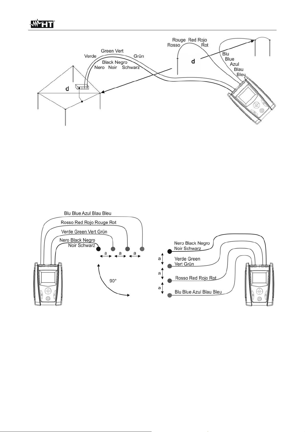
11.3. GROUND RESISTIVITY
This test aims at analyzing the resistivity value of the ground in order to define the type of
rods to be used when designing the installation. For the resistivity test correct or not
correct values do not exist. The various values measured by positioning the rods at
growing distances “a” must be quoted in a graph. According to the resulting curve, suitable
rods will be chosen. As the test result can be affected by metal parts buried such as pipes,
cables or other rods etc., it is advisable in case of doubts to take a second measurement
positioning the rods at an equal distance "a", but rotating their axis by 90°.
Fig. 9: Measurement of ground resistivity
The resistivity value is given by the following relation: E = 2 a R where:
= ground resistivity
E
a = distance between probes [m]
R = resistance measured by the instrument []
EN - 26
Page 28
GEO416 - GEO416GS
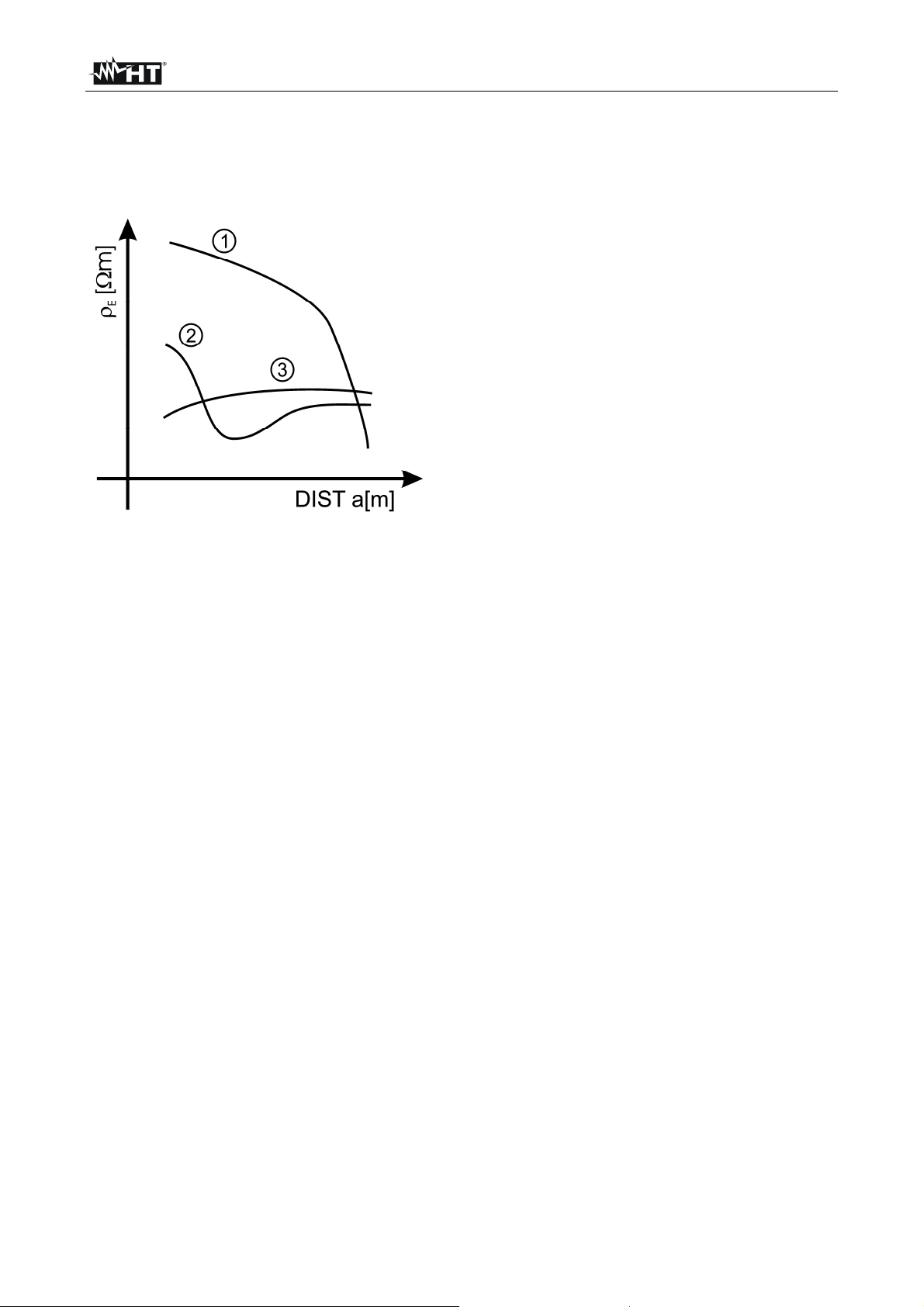
The measuring method allows defining the specific resistivity of a ground layer up to the
depth corresponding approximately to the distance “a” between the rods. If you increase
the distance “a” you can reach deeper ground layers and check the ground homogeneity.
After several measurements you can trace a profile according to which the most suitable
rod is chosen.
Curve 1: as decreases only in depth, it’s
advisable to use a very deep rod
Curve 2: as E decreases only until the depth
a, it’s not useful to increase the
depth of the rod beyond a
Curve 3: the ground resistivity is quite
constant, so increasing depth does
not make E decrease, therefore a
ring rod must be used
Fig. 10: Measurement of ground resistivity
11.3.1. Approximate evaluation of intentional rods' contribution
The resistance of a rod Rd can be calculated with the following formulas ( = average
resistivity of the ground).
a) resistance of a vertical rod
Rd = / L
where L = length of the element touching the ground
b) resistance of an horizontal rod
Rd = 2 / L
where L = length of the element touching the ground
c) resistance of linked elements
The resistance of a complex system made of more elements in parallel is always higher
than the resistance, which could result from a simple calculation of single elements in
parallel, especially if those elements are close to each other and therefore interactive. For
this reason, in case of a linked system the following formula is quicker and more effective
than the calculation of the single horizontal and vertical elements:
Rd = / 4r
where r = radius of the circle which circumscribes the link
EN - 27
Page 29

ESPAÑOL
Manual de instrucciones
Copyright HT ITALIA 2012 Versión ES .0 - 4//2012
Page 30

GEO416 - GEO416GS
Índice:
1. PRECAUCIONES Y MEDIDAS DE SEGURIDAD ........................................................ 2
1.1. Instrucciones preliminares ................................................................................................. 2
1.2. Durante el uso ................................................................................................................... 3
1.3. Después del uso................................................................................................................ 3
1.4. Definición de categoría de medida (sobretensión) ............................................................ 3
2. DESCRIPCIÓN GENERAL ........................................................................................... 4
2.1. Funcionalidad del instrumento .......................................................................................... 4
3. PREPARACIÓN PARA EL USO ................................................................................... 4
3.1. Controles iniciales ............................................................................................................. 4
3.2. Alimentación del instrumento ............................................................................................ 4
3.3. Calibración ........................................................................................................................ 4
3.4. Almacenamiento................................................................................................................ 4
4. INSTRUCCIONES OPERATIVAS ................................................................................ 5
4.1. Descripción del instrumento .............................................................................................. 5
4.2. Descripción de las puntas de prueba ................................................................................ 5
Fig. 2: Descripción de las puntas de prueba ............................................................................................ 5
4.2.1. Encendido ................................................................................................................................ 6
4.2.2. Autoapagado ............................................................................................................................ 6
4.3. EARTH 3W – medición de la resistencia de tierra a 3 puntos .......................................... 7
4.4. EARTH 2W – medición de la resistencia de tierra a 2 puntos .......................................... 9
4.5. - medición de la resistividad del terreno ....................................................................... 12
4.5.1. Situaciones anómalas en mediciones ................................................................................... 15
5. GESTIÓN DE LOS DATOS EN MEMORIA ................................................................ 17
5.1. Como guardar una medida .............................................................................................. 17
5.2. Como cancelar una o más medidas ................................................................................ 17
5.3. Como rellamar una medida ............................................................................................. 18
6. RESET DEL INSTRUMENTO .................................................................................... 19
7. CONEXIÓN DEL INSTRUMENTO AL PC .................................................................. 19
8. MANTENIMIENTO ...................................................................................................... 20
8.1. Generalidades ................................................................................................................. 20
8.2. Cambio de pilas ............................................................................................................... 20
8.3. Limpieza del instrumento ................................................................................................ 20
8.4. Fin de vida ....................................................................................................................... 20
9. ESPECIFICACIONES TÉCNICAS .............................................................................. 21
9.1. Características técnicas .................................................................................................. 21
9.1.1. Normas de referencia ............................................................................................................ 22
9.1.2. Características generales ...................................................................................................... 22
9.2. Ambiente ......................................................................................................................... 22
9.2.1. Condiciones ambientales de uso ........................................................................................... 22
9.3. Accesorios ....................................................................................................................... 22
9.3.1. Accesorios en dotación y opcionales GEO416 ...................................................................... 22
9.3.2. Accesorios en dotación GEO416GS ..................................................................................... 22
10. ASISTENCIA .............................................................................................................. 23
10.1. Condiciones de garantía ................................................................................................. 23
10.2. Asistencia ........................................................................................................................ 23
11. FICHAS PRÁCTICAS PARA LAS VERIFICACIONES ELÉCTRICAS ........................ 24
11.1. Medidas de la resistencia de tierra en los sistemas TT .................................................. 24
11.2. Resistencia tierra método voltiamperimétrico ................................................................. 25
11.2.1. Autoconstrucción del prologador ........................................................................................... 25
11.2.2. Técnica para dispersores de tierra de pequeñas dimensiones ............................................. 25
11.2.3. Técnica para dispersores de tierra de grandes dimensiones ................................................ 25
11.3. Resistividad del terreno ................................................................................................... 26
11.3.1. Valoración aproximada de los dispersores ............................................................................ 27
ES - 1
Page 31

GEO416 - GEO416GS
1. PRECAUCIONES Y MEDIDAS DE SEGURIDAD
El instrumento ha sido proyectado conforme a las directivas IEC/EN61557-1 y IEC/EN
61010-1 relativas a los instrumentos de medida electrónicos.
ATENCIÓN
Para su seguridad y para evitar dañar el instrumento, le rogamos que siga los
procedimientos descritos en el presente manual y lea con particular atención
todas las notas precedidas por el símbolo
Antes y durante la ejecución de las medidas fíjese atentamente en las siguientes
indicaciones:
No efectue medidas en ambientes húmedos, en presencia de gas o materiales
explosivos, combustibles o en ambientes con polvo
Evite el contacto con el circuito en examen si se están efectuando medidas, con partes
metálicas desnudas, terminales de medida inutilizados, etc
No efectúe ninguna medida si existe alguna anomalía en el instrumento como,
deformaciones, roturas, pérdidas de sustancias, ausencia de símbolos en el
visualizador, etc
Preste atención cuando efectúe medidas de tensión superiores a 25V en ambientes
particulares (saunas, piscinas, etc.) y 50V en ambientes ordinarios en cuanto es
presente el riesgo de shock eléctrico.
En el presente manual son utilizados los siguientes símbolos
ATENCIÓN: es necesario consultar el manual de instrucciones con el fin
de detectar el peligro potencial y las acciones a realizar
Aténgase a las instrucciones incluidas en el manual. Un uso inapropiado
pueden causar daños al instrumento y situaciones peligrosas al usuario
Tensión o corriente CC o CA
Peligro tensiones peligrosas: riesgo de shock eléctrico
Instrumento con doble Aislamiento
1.1. INSTRUCCIONES PRELIMINARES
Este instrumento ha sido proyectado para su uso en ambientes de polución 2
Puede ser utilizado para comprobaciones en instalaciones eléctricas con CAT III 240V
respecto tierra con tensiones máximas de 415V entre las entradas
Siga las normales reglas de seguridad orientadas a proteger el usuario de corriente
peligrosas y proteger el instrumento contra un uso inapropiado
Sólo los accesorios incluidos con el equipo garantizan las normas de seguridad.
Deben estar en buenas condiciones y si fuese necesario, sustituirlos por los modelos
originales
No efectúe medidas en circuitos que superen los límites de corriente y tensión
especificados
No efectúe medidas en condiciones ambientales fuera de los límites especificados
Controle que las pilas estén insertadas correctamente
Antes de conectar las puntas de prueba al circuito en examen, controle que el
conmutador esté posicionado correctamente
ES - 2
Page 32

GEO416 - GEO416GS
1.2. DURANTE EL USO
Le rogamos que lea atentamente las recomendaciones y las instrucciones siguientes:
ATENCIÓN
La falta de observación de las Advertencias y/o Instrucciones pueden dañar el
instrumento y/o sus componentes o ser fuente de peligro para el usuario. Si
durante el uso aparece el símbolo de pila agotada, suspenda la prueba y
sustituya las pilas según el procedimiento descrito en el § 8.2
Antes de seleccionar una nueva función desconecte las puntas de prueba del circuito
en examen
Cuando el instrumento se conecta al circuito en examen no tocar nunca cualquier
terminal inutilizado
Evite la medida de la resistencia en presencia de tensiones externas; aunque el
instrumento esté protegido, una tensión excesiva puede causar el malfuncionamiento
del equipo
Evite que el instrumento reciba tensión durante la realización de la medida (por
ejemplo la punta de prueba que resbala desde el punto de medida tocando un punto
con tensión).
1.3. DESPUÉS DEL USO
Cuando las medidas han finalizado apague el instrumento pulsando la tecla ON/OFF
Si se prevé no utilizar el instrumento durante un largo período de tiempo quite las pilas.
1.4. DEFINICIÓN DE CATEGORÍA DE MEDIDA (SOBRETENSIÓN)
La norma IEC/EN61010-1: Prescripciones de seguridad para aparatos eléctricos de
medida, control y para uso en laboratorio, Parte 1: Prescripciones generales, definición de
categoría de medida, comúnmente llamada categoría de sobretensión. En el § 6.7.4:
Circuitos de medida, indica:
Los circuitos están subdivididos en las siguientes categorías de medida:
La categoría IV de medida sirve para las medidas efectuadas sobre una fuente de
una instalación de baja tensión.
Ejemplo: contadores eléctricos y de medidas sobre dispositivos primarios de
protección de las sobrecorrientes y sobre la unidad de regulación de la ondulación.
La categoría III de medida sirve para las medidas efectuadas en instalaciones
interiores de edificios.
Ejemplo: medida sobre paneles de distribución, disyuntores, cableados, incluidos los
cables, los embarrados, los interruptores, las tomas de instalaciones fijas y los
aparatos destinados al uso industrial y otros instrumentación, por ejemplo los motores
fijos con conexionado a instalación fija.
La categoría II de medida sirve para las medidas efectuadas sobre circuitos
conectados directamente a las instalaciones de baja tensión.
Ejemplo: medidas sobre instrumentación para uso doméstico, utensilios portátiles e
instrumentación similar.
La categoría I de medida sirve para las medidas efectuadas sobre circuitos no
conectados directamente a la RED DE DISTRIBUCIÓN.
Ejemplo: medidas sobre no derivados de la RED y derivados de la RED pero con
protección particular (interna). En este último caso las necesidades de transitorios son
variables, por este motivo (OMISSIS) se requiere que el usuario conozca la capacidad
de resistencia a los transitorios de la instrumentación.
ES - 3
Page 33

GEO416 - GEO416GS
2. DESCRIPCIÓN GENERAL
El instrumento está realizado de modo que garantiza la máxima seguridad gracias a un
desarrollo de nueva concepción que asegura el doble aislamiento y el cumplimiento de la
categoría de sobretensión III.
2.1. FUNCIONALIDAD DEL INSTRUMENTO
EARTH 2P: medida de la resistencia de tierra a 2 puntos
EARTH 3P: medida de la resistencia de tierra a 3 puntos
ρ: medida de la resistividad del terreno a 4 puntos
3. PREPARACIÓN PARA EL USO
3.1. CONTROLES INICIALES
El instrumento, antes de ser expedido, ha sido controlado desde el punto de vista eléctrico
y mecánico. Han sido tomadas todas las precauciones posibles con el fin que el
instrumento pueda ser entregado sin ningún daño.
De todas formas se aconseja controlar exhaustivamente el instrumento para comprobar
que no haya sufrido daños durante el transporte. Si se detecta alguna anomalía contacte
inmediatamente con el distribuidor
Se aconseja además controlar que el embalaje contenga todas las partes indicadas en el
§ 9.3. En caso de discrepancias contacte con el distribuidor. En caso de que fuera
necesario devolver el instrumento, se ruega seguir las instrucciones indicadas en el § 10.
3.2. ALIMENTACIÓN DEL INSTRUMENTO
El instrumento está alimentado a pilas (ver § 9.1.2). El estado de carga de las pilas es
indicado sobre el visualizador del instrumento en la parte superior derecha. El símbolo
indica que las pilas están al máximo de la carga, el símbolo indica que las
pilas están descargadas y deben ser sustituidas.
Para sustituir/insertar las pilas siga las instrucciones indicadas en el § 8.2.
3.3. CALIBRACIÓN
El instrumento respeta las características técnicas reflejadas en el presente manual. Las
prestaciones del instrumento están garantizadas durante un año desde la fecha de
adquisición.
3.4. ALMACENAMIENTO
Para garantizar medidas precisas, después de un largo período de almacenamiento en
condiciones ambientales extremas, espere que el instrumento vuelva a las condiciones
normales (ver § 9.2.1)
ES - 4
Page 34

GEO416 - GEO416GS
4. INSTRUCCIONES OPERATIVAS
4.1. DESCRIPCIÓN DEL INSTRUMENTO
LEYENDA:
1. Entradas
2. Tecla ENTER/,,,
3. Tecla ESC/
4. Tecla RCL/CLR
5. Visualizador
6. Tecla GO
7. Tecla SAVE
8. Tecla ON/OFF
Fig. 1: Descripción del instrumento
Tecla ENTER para confirmar la selección
Tecla flecha para mover el cursor seleccionando los parámetros deseados
Tecla para encender la retroiluminación del visualizador durante 30 segundos
Tecla ESC para abandonar la función seleccionada sin confirmar
Tecla RCL para rellamar los datos guardados en memoria
Tecla CLR para cancelar de la memoria la/las medida/s seleccionada/s
Tecla GO para iniciar la ejecución de una medición
Tecla SAVE para guardar la medida en memoria
Tecla ON/OFF para encender/apagar el instrumento
4.2. DESCRIPCIÓN DE LAS PUNTAS DE PRUEBA
LEYENDA:
1. Protector paramano
2. Zona de seguridad
Fig. 2: Descripción de las puntas de prueba
ES - 5
Page 35

GEO416 - GEO416GS
4.2.1. Encendido
Al encender el instrumento emite una breve señal acústica y
durante un segundo se visualizan todos los segmentos del
visualizador.
Sucesivamente muestra la versión del firmware cargada,
luego aparece la última modalidad de medición seleccionada
antes del apagado.
4.2.2. Autoapagado
El instrumento se apaga después de aproximadamente 3 minutos desde el último uso de
las teclas. Para reactivar el instrumento pulse cualquier tecla.
ES - 6
Page 36

GEO416 - GEO416GS
4.3. EARTH 3W – MEDICIÓN DE LA RESISTENCIA DE TIERRA A 3 PUNTOS
La medida será efectuada en acuerdo con la normativa UNE 20460, IEC 781, VDE 0413,
IEC/EN61557-5
ATENCIÓN
El instrumento puede ser utilizado sobre instalaciones con categoría de
sobretensión CAT III 240V respecto tierra con tensiones máximas de 415V
entre las entradas. No conecte el instrumento a una instalación con
tensiones que excedan los límites indicados en este manual. No supere
tales límites, puede causar shock eléctrico al usuario y daños al
instrumento
La conexión de los cables de medida al instrumento y a los cocodrilos
debe ser siempre conectados fuera de la instalación
Se recomienda de empuñar el cocodrillo respetando la zona de seguridad
del protector paramano (ver § 0)
En el caso la longitud de los cables en dotación con el instrumento no sea
el adecuado en la instalación en examen (ver §11) es posible
autoconstruirse un cable con la prolongación adoptando los pasos
descritos en el § 11.2.1
Fig. 3: Medición de la resistencia de tierra a tres puntos
1.
2.
Encienda el instrumento pulsando el botón de ON/OFF
Pulsando las teclas flecha , seleccione MOD, luego pulsando las teclas
flecha , seleccione la función 3W
3. Sobre el visualizador aparece una
ventana como la muestra, donde se
muestra el valor de la tensión de
dispersión en las entradas del
instrumento
Valor de la tensión de
dispersión en las entradas
4. Inserte los cables de medida azul, rojo verde y negro en los correspondientes terminales
de entrada del instrumento H, S, ES, E e inserte, si lo considera necesario, los cocodrilos
ES - 7
Page 37

GEO416 - GEO416GS
5. Prolongue, si fuese necesario, los cables de medida azul y rojo separadamente
utilizando cables de sección adecuada. La presencia de eventuales prolongaciones
no requiere calibración y no modifica el valor de la resistencia de tierra medida
Clave en el terreno los dispersores auxiliares según la distancia prevista por la norma
6.
(§ 11.2)
7. Coloque los cocodrilos a los dispersores auxiliares a la instalación en examen (ver
Fig. 3)
8.
Pulse la tecla GO, el instrumento efectua la medición
9. Mientras el instrumento efectua la
medición será visualizada una ventana
como la muestra donde será mostrado
el valor de la tensión de dispersión en la
entrada del instrumento. Mientras sobre
el visualizador del instrumento aparece
el mensaje no desconecte y no
toque las puntas de prueba
ATENCIÓN
Al inicio de la medición será medida la tensión de dispersión en las entradas
del circuito voltimétrico y amperimétrico. Cualquier valor comprendido entre 3
V y 9 V, el instrumento efectua la medición y visualizará el símbolo
señalando la incertidumbre de la medida (§ 9.1)
10. Al termino de la prueba, en el caso que
la medida de la resistencia de tierra
resulte inferior al fondo de escala, el
instrumento emite una doble señal
acústica indicando el éxito positivo de la
prueba visualizando la medida de la
resistencia y el valor de la tensión de
dispersión detectada
ATENCIÓN
La medida de la resistencia será efectuada con el método voltiamperimétrico
a 4 hilos que no será influenciada por el valor de la resistencia de los cables
utilizados. No es necesario efectuar la compensación de la resistencia de los
cables o de los eventuales prolongadores
11. Al termino de la prueba, en el caso que
la medida de la resistencia de tierra
exceda del fondo de escala, el
instrumento emite una doble señal
acústica indicando el éxito negativo de
la prueba y visualiza la siguiente
ventana
Valor de la tensión de
dispersión en la entrada
Medida de la resistencia
de tierra
Valor de la tensioón de
dispersión en la entrada
Medida de la resistencia
de tierra mayor que el
fondo de escala
Valor de la tensión de
dispersión en la entrada
12.
Las medidas son memorizables pulsando dos veces la tecla SAVE (§ 5.1)
ES - 8
Page 38

GEO416 - GEO416GS
4.4. EARTH 2W – MEDICIÓN DE LA RESISTENCIA DE TIERRA A 2 PUNTOS
ATENCIÓN
El instrumento puede ser utilizado sobre instalaciones con categoría de
sobretensión CAT III 240V respecto tierra con tensiones máximas de 415V
entre las entradas. No conecte el instrumento a una instalación con
tensiones que excedan los límites indicados en este manual. No supere
tales límites, puede causar shock eléctrico al usuario y daños al in
strumento
La conexión de los cables de medida al instrumento y a los cocodrilos
debe ser siempre conectados fuera de la instalación
Se recomienda de empuñar el cocodrillo respetando la zona de seguridad
del protector paramano (ver § 4.2)
En el caso la longitud de los cables en dotación con el instrumento no sea
el adecuado en la instalación en examen (ver § 11) es posible
autoconstruirse un cable con la prolongación adoptando los pasos
descritos en el § 11.2.1
Cuando no sea posible el método a 3 puntos (por ejemplo en el centro histórico), es
posible utilizar el método simplificado a 2 puntos obteniendo un valor superior siendo una
ventaja con respecto a la seguridad. Para efectuar la prueba necesitaremos “un dispersor
auxiliar adecuado”; se entiende como “un dispersor auxiliar adecuado” cuando presenta
una resistencia de tierra razonable e independiente de la instalación de tierra en examen.
En (ver Fig. 4) se está utilizando como dispersor auxiliar el alumbrado público, aunque
puede ser utilizado cualquier cuerpo metálico introducido en el terreno que respete las
condiciones anteriormente comentadas.
ATENCIÓN
El instrumento visualizará como resultado el valor de la suma RA+RT (ver Fig.
4 y Fig. 5). Por tanto la medida obtenida será más aproximada al valor R
A
(valor esperado) cuanto más valor tenga el dispersor auxiliar RT resultando
despreciable respecto a la misma R
favor de la seguridad” sobre el termino R
igual con las protecciones, con mayor motivo solo será el termino R
. Además la medida será aumentada “a
A
, osea cuando el valor RA+RT resulte
T
A
Fig. 4: Medición de la resistencia de tierra a dos puntos utilizando un dispersor auxiliar
En los sistemas TT (ver Fig. 5) es posible efectuar la medida de tierra a 2 puntos
utilizando como dispersor auxiliar el conductor de neutro incluido en la instalación,
conectando directamente en la toma de corriente o del cuadro de alimentación; si en la
toma es disponible el conexionado de tierra evidentemente la medida puede ser efectuada
directamente en la toma, entre los conductores de neutro y de tierra.
ES - 9
Page 39

GEO416 - GEO416GS
ATENCIÓN
Si se desea efectuar la medida utilizando el conductor de neutro y de tierra de
una toma de corriente, evite conectar accidentalmente sobre la fase; en cuyo
caso el visualizador indicará la tensión detectada, aparecerá el símbolo de
ATENCIÓN con la señal de advertencia y no podrá efectuar la medida
aunque pulse la tecla GO
Fig. 5: Medición de la resistencia de tierra a dos puntos desde el cuadro de alimentación
1.
2.
Encienda el instrumento pulsando el botón ON/OFF
Pulsando las teclas flecha , seleccione MOD, luego pulsando las teclas
flecha , seleccione la función 2W
3. Sobre el visualizador aparece la
siguiente pantalla indicando el valor de
la tensión de dispersión en las entradas
del instrumento
Valor de la tensión de
dispersión en las entradas
4. Inserte los cables de medida azul, rojo, verde y negro en el correspondiente
terminales de entrada del instrumento H, S, ES, E e inserte, si es necesario, los
cocodrilos
5. Prolongue, si fuese necesario, los cables de medida azul y rojo separadamente
utilizando cables de sección adecuada. La presencia de eventuales prolongaciones
no requiere calibración y no modifica el valor de la resistencia de tierra medida
Conecte los cocodrilos al dispersor auxiliar de la instalación en examen (ver Fig. 4
6.
Fig. 5)
7.
Pulse la tecla GO, el instrumento efectua la medición
ES - 10
Page 40

GEO416 - GEO416GS
8. Mientras el instrumento efectua la
medición será visualizada una ventana
como la muestra donde será mostrado
el valor de la tensión de dispersión en la
entrada del instrumento. Mientras sobre
el visualizador del instrumento aparece
el mensaje
toque las puntas de prueba
ATENCIÓN
no desconecte y no
Al inicio de la medición será medida la tensión de dispersión en las entradas
del circuito voltimétrico y amperimétrico. Cualquier valor comprendido entre 3
V y 9 V, el instrumento efectua la medición y visualizará el símbolo
señalando la incertidumbre de la medida (§ 9.1)
9. Al termino de la prueba, en el caso que
la medida de la resistencia de tierra
resulte inferior al fondo de escala, el
instrumento emite una doble señal
acústica indicando el éxito positivo de la
prueba y visualiza la medida de la
resistencia y el valor de la tensión de
dispersión detectada
ATENCIÓN
La medida de la resistencia será efectuada con el método voltiamperimétrico
a 4 hilos que no será influenciada por el valor de la resistencia de los cables
utilizados. No es necesario efectuar la compensación de la resistencia de los
cables o de los eventuales prolongadores
10. Al termino de la prueba, en el caso que
la medida de la resistencia de tierra
exceda del fondo de escala, el
instrumento emite una doble señal
acústica indicando el éxito negativo de
la prueba y visualiza la siguiente
ventana
Valor de la tensión de
dispersión en la entrada
Medida de la resistencia
de tierra
Valor de la tensión de
dispersión en las entradas
Medida de la resistencia
de tierra mayor que el
fondo de escala
Valor de la tensión de
dispersión en la entrada
11.
Las medidas son memorizables pulsando dos veces la tecla SAVE (§ 5.1)
ES - 11
Page 41

GEO416 - GEO416GS
4.5. - MEDICIÓN DE LA RESISTIVIDAD DEL TERRENO
El valor de la resistividad del terreno es un parámetro indispensable para calcular el valor
de la resistencia de los dispersores que se van a utilizar para la realización de una
instalación de tierra. La medida será efectuada en acuerdo con las normativas UNE
20460, IEC 781, VDE 0413, IEC/EN61557-5.
ATENCIÓN
El instrumento puede ser utilizado sobre instalaciones con categoría de
sobretensión CAT III 240V respecto tierra con tensiones máximas de 415V
entre las entradas. No conecte el instrumento a una instalación con
tensiones que excedan los límites indicados en este manual. No supere
tales límites, puede causar shock eléctrico al usuario y daños al
instrumento
La conexión de los cables de medida al instrumento y a los cocodrilos
debe ser siempre conectados fuera de la instalación
Se recomienda de empuñar el cocodrillo respetando la zona de seguridad
del protector paramano (ver § 4.2)
En el caso la longitud de los cables en dotación con el instrumento no sea
el adecuado en la instalación en examen (ver § 11) es posible
autoconstruirse un cable con la prolongación adoptando los pasos
descritos en el § 11.2.1
1.
2.
Encienda el instrumento pulsando el botón ON/OFF
Pulsando las teclas flecha , seleccione MOD, luego pulsando las teclas
flecha , seleccione la función
Fig. 6: Medición de la resistividad del terreno
ES - 12
Page 42

GEO416 - GEO416GS
3. Sobre el visualizador aparece la
siguiente pantalla donde nos muestra el
valor de la tensión de dispersión en las
entradas del instrumento y el valor de la
distancia entre los dispersores
seleccionados
Valor de la tensión de
dispersión en las entradas
y de la distancia entre los
dispersores configurado
Cuando se desee modificar la
4.
distancia entre los dispersores
pulse las teclas flecha , y
seleccione DIST, después pulse
las teclas flecha ,
configurando la distancia
deseada (desde uno a diez
Valor de la distancia entre
los dispersores
seleccionados
metros, con pasos de uno o
bien de tres a trenta pies a
pasos de tres)
Para configurar la unidad de
5.
medida de la distancia pulse las
teclas flecha , y seleccione
UNIT, después pulsando las
teclas flecha , configure la
unidad de medida deseada (m
o bien ft)
Unidad de medida
configurada
6. Inserte los cables de medida azul, rojo, verde y negro en los correspondientes
terminales de las entradas del instrumento H, S, ES, E, e inserte, si es necesario los
cocodrilos
7. Prolongue, si fuese necesario, los cables de medida azul y rojo separadamente
utilizando cables de sección adecuada. La presencia de eventuales prolongaciones
no requiere calibración y no modifica el valor de la resistencia de tierra medida
8. Clave en el terreno cuatro dispersores en línea y colocándolos a una distancia igual a
la seleccionada por el instrumento. La configuración de una distancia diferente de la
que realmente hay presente entre los dispersores de la medida (§11.3)
9. Conecte los cocodrilos a los dispersores (ver Fig. 6)
10.
Pulse la tecla GO, el instrumento efectua la medida
ES - 13
Page 43

GEO416 - GEO416GS
11. Mientras el instrumento efectua la
medición será visualizada una ventana
como la muestra donde será mostrado
el valor de la tensión de dispersión en la
entrada del instrumento. Mientras sobre
el visualizador del instrumento aparece
el mensaje
toque las puntas de prueba
ATENCIÓN
no desconecte y no
Al inicio de la medición será medida la tensión de dispersión en las entradas
del circuito voltimétrico y amperimétrico. Cualquier valor comprendido entre 3
V y 9 V, el instrumento efectua la medición y visualizará el símbolo
señalando la incertidumbre de la medida (§ 9.1)
12. Al termino de la prueba, en el caso en
cuya medida de la resistividad resulta
inferior al fondo de escala, el
instrumento emite un doble señal
acústica indicando el éxito positivo de la
prueba y visualiza la medida de la
resistividad y el valor de la tensión de
dispersión presente al lado del valor
medido
ATENCIÓN
La medición de la resistividad será efectuada con el método
voltiamperimétrico a 4 hilos que no será influenciada por el valor de la
resistencia de los cables utilizados. No será necesario efectuar la
compensación de la resistencia de los cables o de los eventuales
prolongadores
13. Al termino de la prueba, en el caso en
que la medida de la resistividad de
tierra exceda del fondo de escala, el
instrumento emite un señal acústica
prolongada indicando el éxito negativo
de la prueba y visualizará la siguiente
pantalla
ATENCIÓN
El fondo de escala será calculado como ρ
= 2 DIST R donde DIST es el
MAX
valor configurado de la distancia entre dispersores y R el máximo valor de
resistencia medible por el instrumento. El fondo de escala de la medición de
resistividad de tierra depende por tanto de la configuración de la distancia
entre los dispersores
Valor de la tensión de
dispersión en las entradas
y de la distancia entre los
dispersores configurados
Medida de la resistividad
del terreno
Valor de la tensión de
dispersión en las entradas
y de la distancia entre los
dispersores configurados
Medida de la resistividad
del terreno mayor del
fondo de escala
Valor de la tensión de
dispersión en las entradas
y de la distancia entre los
dispersores configurados
14.
Las medidas son memorizables pulsando dos veces la tecla SAVE (§ 5.1)
ES - 14
Page 44

GEO416 - GEO416GS
4.5.1. Situaciones anómalas en mediciones
1. Al inicio de la medición el instrumento
verifica la continuidad de los cables de
medida. Cuando el circuito
voltimétrico (cable rojo S y verde ES)
esté interrumpido o presente una
resistencia muy elevada, el
instrumento visualiza la siguiente
pantalla. Controle que los terminales
estén correctamente conectados y que
el dispersor conectado al terminal S no
Resistencia del circuito
voltimétrico muy elevada
Valor de la tensión de
dispersión en las entradas
Ejemplo en modalidad 3W
esté clavado en terreno rocoso o escasamente conductivo, en tal caso vierta agua
entorno al dispersor para disminuir la resistencia (§ 11.2).
Será visualizado RP>top cuando:
Al circuito voltimétrico se sume una resistencia del dispersor S RS > 50KΩ
La resistencia del dispersor S supera el valor 1200 + 100 RX [Ω] (donde RX es
el valor medido de la resistencia de tierra)
2. Al inicio de la medición el instrumento
verifica la continuidad de los cables de
medida. Cuando el circuito
amperimétrico (cable azul H y negro
Resistencia del circuito
amperimétrico muy
elevada
E) esté interrumpido o presente una
resistencia muy elevada, el
instrumento visualiza la siguiente
pantalla. Controle que los terminales
estén correctamente conectados y que
el dispersor conectado al terminal H no
Valor de la tensión de
dispersión en las entradas
Ejemplo en modalidad 3W
esté clavado en terreno rocoso o o escasamente conductivo, en tal caso vierta agua
entorno al dispersor para disminuir la resistencia (§ 11.2).
Será visualizado RC>top cuando:
Al circuito amperimétrico se suma una resistencia del dispersor H RH > 50KΩ
3. Al inicio de la medición el instrumento
La resistencia del dispersor H supera el valor 1200 + 100 R
el valor medido de la resistencia de tierra)
verifica la continuidad de los cables de
medida. Cuando el circuito
voltimétrico (cable rojo S y verde ES)
y el circuito amperimétrico (cable
azul H y negro E) estén
interrumpidos o presenten una
resistencia muy elevada, el
instrumento visualiza la siguiente
pantalla. Controle que los terminales
X [Ω] (donde RX es
Resistencia del circuito
amperimétrico y
voltmétrico muy elevada
Valor de la tensión de
dispersión en las entradas
Ejemplo en modalidad 3W
estén correctamente conectados y que los dispersores conectados a los terminales S
y H no estén clavados en terreno rocoso o escasamente conductivos, en tal caso
vierta agua entorno al dispersor para disminuir la resistencia (§ 11.2).
Será visualizado RP y RC>top cuando:
Al circuito voltimétrico se suma una resistencia del dispersor S RS > 50KΩ y al
circuito amperimétrico se suma una resistencia del dispersor H RH > 50KΩ
La resistencia del dispersor S y la resistencia del dispersor H superan el valor
1200 + 100 RX [Ω] (donde RX es el valor medido de la resistencia de tierra)
ES - 15
Page 45

GEO416 - GEO416GS
4. Al inicio de la medición, cuando los
cables rojo (conectado al terminal S)
y verde (conectado al terminal ES)
estén invertidos entre ellos, el
instrumento no efectua la prueba, emite
un señal acústica prolongada y
visualizará la siguiente pantalla
5. Al inicio de la medición, cuando el
instrumento detecta en las entradas
del circuito voltimétrico una tensión
de dispersión superior a 9V, no
efectua la prueba, emite una señal
acústica prolongada y visualiza la
siguiente pantalla
6. Al inicio de la medición, cuando el
instrumento detecta en las entradas
del circuito amperimétrico una
tensión de dispersión superior a 9V,
no efectua la prueba, emite una señal
acústica prolongada y visualiza la
siguiente pantalla
7. Al inicio de la medición, cuando el
instrumento detecta en las entradas
de los circuitos voltimétrico y
amperimétrico una tensión de
dispersión superior a 9V, no efectua
la prueba, emite una señal acústica
prolongada y visualiza la siguiente
pantalla
8. Cuando la tensión generada por las
pilas no es suficiente, el instrumento
visualiza el símbolo de pila descargada
y el mensaje , después no
permite la ejecución de ninguna
medición. En esta condición es posible
efectuar operaciones como
configuración, lectura de los datos en
memoria, etc
Cable rojo y verde
invertidos entre ellos
Ejemplo en modalidad ρ
Tensión de dispersión en
las entradas del circuito
voltimétrico muy elevada
Valor de la tensión de
dispersión en las entradas
Ejemplo en modalidad 2W
Tensión de dispersión en
las entradas del circuito
amperimétrico muy
elevada
Valor de la tensión de
dispersión en las entradas
Ejemplo en modalidad 2W
Tensión de dispersión en
las entradas del circuito
voltimétrico o
amperimétrico muy
elevada
Valor de la tensión de
dispersión en las entradas
Ejemplo en modalidad 2W
Tensión de alimentación
muy baja, pilas agotadas
Valor de la tensión de
dispersión en las entradas
y de la distancia entre los
dispersores configurados
Ejemplo en modalidad ρ
9.
Las situaciones anómalas anteriores no son memorizables
ES - 16
Page 46

GEO416 - GEO416GS
5. GESTIÓN DE LOS DATOS EN MEMORIA
5.1. COMO GUARDAR UNA MEDIDA
1.
2.
3.
5.2. COMO CANCELAR UNA O MÁS MEDIDAS
1.
Después de haber efectuado
una medición pulse la tecla
SAVE, el instrumento visualiza
la siguiente pantalla
Cuando se desea modificar los valores de los parámetros L y P pulse las
teclas flecha, y seleccione L o bien P, después pulsando las teclas
flecha, configure el valor deseado (desde 1 a 255). Este valor puede
ayudar a recordar el lugar en el cual se ha efectuado la medición
O BIEN
Confirme el salvado de la medida pulsando la tecla SAVE o
bien la tecla ENTER
Pulse la tecla RCL, el
instrumento visualiza la
siguiente pantalla
Número de la localización
de memoria en la cual
será memorizada la
medida
Útimo valor guardado del
parámetro L y del
parámetro P
Número de la última localización de memoria
utilizada
Pulse las teclas flecha ,
2.
para seleccionar la casilla de
memoria de la cual iniciar la
cancelación de los datos, el
instrumento visualiza la
siguiente pantalla
ATENCIÓN
La confirmación de la cancelación de los datos comporta el traslado de todos
los datos memorizados a partir de la celda seleccionada hasta la última celda
de memoria ocupada
Valores del parámetro L y
del parámetro P
Número de la localización
de memoria del cual iniciar
la cancelación
Valores del parámetro L y
del parámetro P
ES - 17
Page 47

GEO416 - GEO416GS
Pulse la tecla CLR, el
3.
instrumento visualiza la
siguiente pantalla
En alternativa:
Confirmar la cancelación de las medidas pulsando la tecla ENTER, el
4.
instrumento emite una doble señal acústica indicando la cancelación
de las medidas seleccionadas
O bien:
4.
Pulse la tecla ESC para volver a la visualización anterior
5.3. COMO RELLAMAR UNA MEDIDA
Pulse la tecla RCL, el
1.
instrumento visualiza la
siguiente pantalla
Primera y última
localización de memoria
cancelada y confirmada
Número de la última
localización de memoria
utilizada
Pulse las teclas flecha ,
2.
para seleccionar la localización
de memoria de la cual se quiere
visualizar el contenido
Pulse la tecla ENTER para
3.
4.
visualizar la medida contenida
en la localización de memoria
seleccionada, el instrumento
visualiza la siguiente pantalla
Pulse la tecla ESC para volver a la visualización anterior y pulse nuevamente
la tecla ESC para salir de la gestión de la memoria
ES - 18
Valores del parámetro L y
del parámetro P
Número de la localización
de memoria de la cual se
quiere visualizar el
contenido
Valores del parámetro L y
del parámetro P
Medida memorizada en la
localización de memoria
seleccionada
Valores de la tensión de
dispersión presente al lado
de la medición
Page 48

GEO416 - GEO416GS
6. RESET DEL INSTRUMENTO
ATENCIÓN
ANTES DE EJECUTAR EL RESET AL INSTRUMENTO GUARDE LOS
DATOS RELATIVOS A LAS MEDIDAS EFECTUADAS
TRANSFIRIENDOLAS A UN PC
1.
2.
Antes de encender el instrumento pulse la tecla RCL/CLR
Mantenga pulsada la tecla RCL/CLR, pulse la
tecla de encendido. El instrumento emite un breve
señal acústica y durante un segundo muestra
todos los segmentos del visualizador. Después
ATENCIÓN
emite una breve señal acústica y se visualiza la
siguiente pantalla durante 3 segundos
El procedimiento del hard reset comporta la cancelación definitiva de todos los
datos residentes en memoria y del parámetro DIST al valor por defecto (1m o
3ft)
7. CONEXIÓN DEL INSTRUMENTO AL PC
La conexión entre el PC y el instrumento es a través del puerto Serie o USB y cable
optoaislado incluido unicamente en el paquete software. Antes de efectuar el conexionado
es necesario seleccionar sobre el PC el puerto utilizado y la velocidad de transmisión
correcta (9600 bps). Para configurar este parámetro ejecute el software y consulte la
Ayuda en línea del programa. El puerto seleccionado no debe ser ocupado por otro
dispositivo o aplicación como ratón, módem, etc. Para transferir los datos memorizados al
PC aténgase al siguiente procedimiento:
ATENCIÓN
El puerto óptico emite radiaciones Láser, no mire directamente las entradas
en los instrumentos ópticos. Láser de clase 1M según EN 60825-1.
1.
Encienda el instrumento pulsando la tecla ON/OFF
Conecte el instrumento al PC por medio del cable optoaislado incluido unicamente al
2.
paquete software. La comunicación es habilitada en cada función a excepción de
la fase de medición y mientras se activa la gestión de la memoria (§ 5)
3. Utilice el programa de gestión de los datos para
descargar al PC el contenido en la memoria del
instrumento. Durante la transferencia de los datos del
instrumento se visualiza la siguiente pantalla, después,
acabada la transferencia de los datos vuelve a la función
anteriormente seleccionada
ES - 19
Page 49

GEO416 - GEO416GS
8. MANTENIMIENTO
8.1. GENERALIDADES
El instrumento que Usted ha adquirido es un instrumento de precisión. Durante el uso y el
almacenamiento respete las recomendaciones enumeradas en este manual para evitar
posibles daños o peligros durante el uso.
No utilice el instrumento en entornos caracterizados por elevadas tasas de humedad o
temperatura. No lo exponga directamente a la luz del sol.
Apague siempre el instrumento después del uso. Si prevé no utilizarlo por un largo
periodo de tiempo quite las pilas para evitar derrame de líquidos que puedan perjudicar
los circuitos internos del instrumento.
8.2. CAMBIO DE PILAS
Cuando en el visualizador LCD aparezca el símbolo de pilas descargadas (ver § 9.1.2)
sustituya las pilas.
ATENCIÓN
Sólo técnicos cualificados pueden efectuar esta operación. Antes de efectuar
esta operación asegúrese de haber desconectado todos los cables de los
terminales de entrada
1. Apague el instrumento pulsando continuamente la tecla ON/OFF
2. Desconecte los cables de los terminales de entrada
3. Quite el tornillo de fijación de la tapa de pilas
4. Quite la tapa de pilas, todas las pilas y sustituirlas sólo con pilas nuevas y del mismo
tipo (ver § 9.1.2) respetando las polaridades indicadas
5. Poner de nuevo la tapa de pilas y fíjela con los tornillos
6. No disperse en el ambiente las pilas utilizadas. Use los contenedores especiales para
su tratamiento
8.3. LIMPIEZA DEL INSTRUMENTO
Para la limpieza del instrumento utilice un paño limpio y seco. No use nunca paños
húmedos, disolvente, agua, etc.
8.4. FIN DE VIDA
Atención: el símbolo indica que el aparato y sus accesorios deben ser
reciclados separadamente y tratado de modo correcto.
ES - 20
Page 50

GEO416 - GEO416GS
9. ESPECIFICACIONES TÉCNICAS
9.1. CARACTERÍSTICAS TÉCNICAS
Incertidumbre indicada es [%lectura + (número digs*resolución)] a 23°C±5°C, < 80%HR
Mediciones de la resistencia de tierra a 3 y a 2 puntos - EARTH 3W y EARTH 2W
Escala (**)
Lectura [] Medida []
0.01 19.99 0.08 19.99
20.0 199.9 20.0 199.9
200 1999 200 1999
2.00 19.99k 2.00 19.99k
20.0 49.9k 20.0 49.9k
Resolución []
0.01
0.1
1
0.01k
0.1k
Medición de la resistividad del terreno - (distancia entre dispersores=1m)
Escala (**)
Lectura [m] Medida [m]
0.06 19.99 0.50 19.99
20.0 199.9 20.0 199.9
200 1999 200 1999
2.00 19.99k 2.00 19.99k
20.0 199.9k 20.0 49.9k
200 314k 200 314k
Frecuencia de medida: 77.5Hz; Corriente de prueba: 12mA; Tensión en vacío: < 25Vrms
Tensión de dispersión sobre el circuito amperimétrico y voltimétrico: la medida será efectuada con la precisión
declarada para tensiones de dispersión 3V, para tensiones de dispersión > 3V y 9V la precisión del instrumento
disminuye progresivamente. Para tensiones de dispersión igual a 9V el instrumento no efectua la medición
(*) Cuando: RP > 1200 + 100 RX y/o RC > 1200 + 100 RX, RP > 50k y/o RC > 50k y el instrumento efectua la
medición, su precisión es igual a (10% lectura) donde:
RP = resistencia del circuito de tensión; RC = resistencia del circuito de corriente ; RX = resistencia de tierra medida
(**) Selección automática de la escala de medida
Resolución [m]
0.01
0.1
1
0.01k
0.1k
1k
Medición de la tensión de dispersión
Escala (**)
Lectura [V] Medida [V]
0 460 7 460
(**) Selección automática de la escala de medida
Resolución [V] Incertidumbre
1
Incertidumbre (*)
(2.5%lectura + 2cifras)
Incertidumbre (*)
(2.5%lectura + 2cifras)
(2.0% lectura + 2cifras)
ES - 21
Page 51

GEO416 - GEO416GS
9.1.1. Normas de referencia
Seguridad: IEC/EN61010-1, IEC/EN61557-1, IEC/EN61557-5
Seguridad accesorios de medida: IEC/EN61010-031, IEC/EN61010-2-032
Documentación técnica: IEC/EN61187
Aislamiento: doble aislamiento
Protección: IP50 según IEC / EN60529
Nivel de polución: 2
Categoría de sobretensión: CAT III 240V (respecto tierra), max 415V entre entradas
Altitud máx de uso: 2000m
9.1.2. Características generales
Características mecánicas
Dimensiones (A x An x H): 235 x 165 x 75mm
Peso (pila incluida): aprox. 1kg
Alimentación
Tipo pilas: 6x1.5V pilas tipo AA LR6 o bien
6x1.2V pilas recargables Ni-MH tipo AA LR6 2100mA
Indicación pila descargada: aparece el símbolo sobre el visualizador
Duración pilas: aprox. 500 pruebas
Autoapagado: después de 3 minutos sin uso
Visualizador
Características: LCD custom con retroiluminación 73 x 65 mm
Memoria
Características: 999 localizaciones de memoria
Conexión a un PC
Características: puerto optoaislado para comunicaciones bidireccionales
9.2. AMBIENTE
9.2.1. Condiciones ambientales de uso
Temperatura de referencia: 23 ± 5°C
Temperatura de uso: 0 ÷ 40°C
Humedad relativa admitida: <80%HR
Temperatura de almacenamiento: -10 ÷ 60°C
Humedad de almacenamiento: <80%HR
Este instrumento es conforme a los requisitos de la Directiva Europea sobre baja
tensión 2006/95/CE (LVD) y de la directiva EMC 2004/108/CE
9.3. ACCESORIOS
9.3.1. Accesorios en dotación y opcionales GEO416
Ver lista adjunta
9.3.2. Accesorios en dotación GEO416GS
Conjunto 4 cables banana-banana L=1m KIT416CV
Conjunto de 4 cocodrilos COC4-UK
Bolsa de transporte BORSA2000N
Certificado de calibración ISO9000
Manual de instrucciones
ES - 22
Page 52

GEO416 - GEO416GS
10. ASISTENCIA
10.1. CONDICIONES DE GARANTIA
Este instrumento está garantizado contra cada defecto de materiales y fabricaciones,
conforme con las condiciones generales de venta. Durante el período de garantía, las
partes defectuosas pueden ser sustituidas, pero el fabricante se reserva el derecho de
repararlo o bien sustituir el producto.
Siempre que el instrumento deba ser reenviado al servicio post - venta o a un distribuidor,
el transporte será a cargo del cliente. La expedición deberá, en cada caso, ser
previamente acordada.
Acompañando a la expedición debe ser incluida una nota explicativa sobre los motivos del
envío del instrumento.
Para la expedición utilice sólo en embalaje original, cada daño causado por el uso de
embalajes no originales será a cargo del cliente.
El fabricante declina toda responsabilidad por daños causados a personas o objetos.
La garantía no se aplica en los siguientes casos:
Reparaciones y/o sustituciones de accesorios y pilas (no cubiertas por la garantía).
Reparaciones que se deban a causa de un error de uso del instrumento o de su uso
con aparatos no compatibles.
Reparaciones que se deban a causa de embalajes no adecuados.
Reparaciones que se deban a la intervención de personal no autorizado.
Modificaciones realizadas al instrumento sin explícita autorización del fabricante.
Uso no contemplado en las especificaciones del instrumento o en el manual de uso.
El contenido del presente manual no puede ser reproducido de ninguna forma sin la
autorización del fabricante.
Nuestros productos están patentados y la marca registrada. El fabricante se reserva
en derecho de aportar modificaciones a las características y a los precios si esto es
una mejora tecnológica.
10.2. ASISTENCIA
Si el instrumento no funciona correctamente, antes de contactar con el servicio de
asistencia, controle el estado de las pilas, de los cables y sustitúyalos si fuese necesario.
Si el instrumento continúa manifestando un mal funcionamiento controle si el
procedimiento de uso del mismo es correcto según lo indicado en el presente manual.
Si el instrumento debe ser reenviado al servicio post venta o a un distribuidor, el
transporte es a cargo del Cliente. La expedición deberá, en cada caso, previamente ser
acordada.
Acompañando a la expedición debe incluirse siempre una nota explicativa sobre el motivo
del envío del instrumento.
Para la expedición utilice sólo el embalaje original, daños causados por el uso de
embalajes no originales serán a cargo del Cliente.
ES - 23
Page 53

GEO416 - GEO416GS
11. FICHAS PRÁCTICAS PARA LAS VERIFICACIONES ELÉCTRICAS
11.1. MEDIDAS DE LA RESISTENCIA DE TIERRA EN LOS SISTEMAS TT
Verificar que el dispositivo de protección sea coordinado con el valor de la resistencia de
tierra. No se puede asumir a priori un valor de resistencia de tierra límite de referencia al
que hacer referencia en el control del resultado de la medida, pero es necesario en su
momento controlar que sea respetado la coordinación prevista por la normativa.
Las partes de una instalación a verificar son representadas en el interior de la instalación
de tierra en las condiciones del ejercicio. La verificación debe ser efectuada sin
desconectar los dispersores.
El valor de la resistencia de tierra medida tiene que satisfacer la siguiente relación RA < 50
/ Ia donde:
RA = resistencia medida de la instalación de tierra, el valor puede ser determinado con
las siguientes medidas:
Resistencia de tierra con el método voltiamperimétrico a tres hilos
Resistencia de tierra con el método voltiamperimétrico a dos hilos
Impedancia del bucle de avería (*)
Resistencia de tierra a dos hilos en la toma de corriente (**)
Resistencia de tierra dada la medida de la tensión de contacto Ut
Resistencia de tierra dada la medida de la prueba del tiempo de intervención de
los interruptores diferenciales RCD (A, AC), RCD S (A, AC) (**)
Ia = corriente de intervención en 5s del interruptor automático, corriente nominal de
intervención del diferencial (en el caso de RCD S 2 In) expresado en Amperios
50 = tensión límite de seguridad (reducida a 25V en ambientes particulares)
(*) Si la protección de la instalación se encuentra un interruptor diferencial la medida
tiene que ser efectuada aguas arriba del mismo diferencial o aguas abajo
excluyendo el mismo para evitar que éste intervenga (obteniendo la mayor
seguridad por el peligro que representa)
(**) Estos métodos, incluso si no están actualmente previstos por las normas, proveen
valores que innumerables pruebas de comparación con el método a tres puntos
han demostrado ser indicativos de la resistencia de tierra
Ejemplo
Nos encontramos en una instalación protegida por un diferencial de 30 mA. Medimos la
resistencia de tierra utilizando uno de los métodos anteriormente citados. Para considerar
la resistencia de la instalación dentro de la norma multiplicando el valor obtenido por
0.03A (30 mA), el resultado debe ser inferior a 50V (o 25V para entornos particulares)
respetando así la relación indicada anteriormente.
Cuando estamos en presencia de diferenciales de 30 mA (la casi totalidad de las
instalaciones domésticas) la resistencia de tierra máxima admitida es 50/0.03=1666 ésta
permite también utilizar los métodos simplificados indicados que, incluso no obteniendo un
valor extremadamente preciso, es suficientemente aproximado para el cálculo de la
coordinación.
ES - 24
Page 54

GEO416 - GEO416GS
11.2. RESISTENCIA TIERRA MÉTODO VOLTIAMPERIMÉTRICO
11.2.1. Autoconstrucción del prologador
En el caso que la longitud de los cables incluidos en dotación con el instrumento no es
suficiente, es posible realizar un prolongador para efectuar la medida en la instalación en
examen sin despreciar la precisión del mismo instrumento.
Para la construcción del prolongador adopte siempre las siguientes indicaciones para
garantizar la seguridad del usuario:
Utilice siempre cables caracterizados para tensión de aislamiento y clase de
aislamiento adecuado a la tensión nominal y categoría de medida (sobretensión) de la
instalación en examen
Para los terminales de prolongación, utilice siempre conectores de Categoría de
medida (sobretensión) y tensión adecuada en el punto el cual se intenta conectar el
instrumento (ver § 1.4). Se recomienda el uso de acesorio opcional 1066-IECN
11.2.2. Técnica para dispersores de tierra de pequeñas dimensiones
Haciendo circular una corriente entre el dispersor de tierra en examen y el dispersor
auxiliar de corriente posicionada a una distancia en línea recta de la instalación de tierra
igual a 5 veces la diagonal del area que delimita la instalación del anillo de tierra (ver
siguiente figura). Posicione el dispersor auxiliar de tensión lo más aproximado a la mitad
entre el anillo o dispersor de tierra y el dispersor auxiliar de corriente, y mida la tensión
entre los dos.
Fig. 7: Medición de la resistencia de tierra - anillos de pequeñas dimensiones
11.2.3. Técnica para dispersores de tierra de grandes dimensiones
Esta técnica está siempre basada en el método voltiamperimétrico pero se utiliza en caso
de que resulte dificultoso el conexionado del dispersor auxiliar de corriente a una distancia
igual a 5 veces la diagonal del área de la instalación de tierra a examen. Posicione el
dispersor auxiliar de corriente a una distancia igual a una vez la diagonal de la
instalación de tierra en examen (ver Fig. 8). Para verificar que el dispersor auxiliar de
tensión esté situado fuera de las zonas de influencia del anillo de tierra en prueba, efectue
más medidas partiendo con el dispersor auxiliar de tensión situado en el punto intermedio
entre el anillo y el dispersor auxiliar de corriente y sucesivamente desplazando el
dispersor auxiliar hacia el anillo de tierra y hacia el dispersor auxiliar de corriente.
ES - 25
Page 55

GEO416 - GEO416GS
11.3. RESISTIVIDAD DEL TERRENO
La misión de la prueba es analizar el valor de la resistividad del terreno para definir, en
fase de proyectación, la tipologia de los dispersores de tierra a utilizar en una instalación.
Para la medida de la resistividad no existen valores correctos o incorrectos, los distintos
valores obtenidos utilizando distancias entre las picas “a” crecientes deben ser mostradas
en un gráfico del cual, en función de la curva obtenida, se establece el tipo de dispersor a
utilizar. Aunque la medida puede ser falseada por partes metálicas enterradas como
tuberías, cables, otros dispersores, etc. Es aconsejable efectuar una segunda medición
con igual distancia “a” rotando el eje 90º de las picas.
Fig. 8: Medición de la resistencia de tierra - anillos de grandes dimensiones
Fig. 9: Medición de la resistividad del terreno
El valor de la resistividad es dado de la siguiente relación: E = 2 a R donde:
E = resistividad especifica del terreno
a = distancia entre dispersores auxiliares [m]
R = resistencia medida por el instrumento []
ES - 26
Page 56

GEO416 - GEO416GS
El método de medida permite de obtener la resistividad especifica hasta la profundidad
correspondiente aproximadamente de la distancia “a“ entre dos dispersores auxiliares.
Usted si aumenta “a “puede obtener lecturas a más profundidad de terreno, por tanto es
posible controlar la homogeneidad del terreno. Varias medidas de , con “a“ creciente, se
puede trazar un perfil como la fig. 9 del que es posible establecer el uso de la conexión
con tierra más idónea. Es decir:
Curva 1: ya que sólo disminuye en
profundidad es posible sólo utilizar
un dispersor en profundidad
Curva 2: ya que disminuye sólo hasta la
profundidad media, el aumento de la
profundidad comporta ninguna
ventaja
Curva 3: con el aumento de la profundidad no
se obtiene ninguna disminución de .
Por tanto el tipo de dispersor a
utilizar es el dispersor de anillo o de
superficie
Fig. 10: Medición de la resistividad del terreno
11.3.1. Valoración aproximada de los dispersores
En primer lugar la resistencia de una conexión con tierra Rd puede ser calculada con las
siguientes fórmulas ( resistividad media del terreno).
a) Resistencia de un dispersor vertical
Rd = / L
donde L = longitud del elemento de contacto con el terreno
b) Resistencia de un dispersor horizontal
Rd = 2 / L
donde L = longitud del elemento de contacto con el terreno
c) Resistencia de un sistema de elemento enmallado
Como es conocido la resistencia de un sistema complejo con más elementos en paralelo
es cada vez más elevada de la que resultaría de un simple cálculo de elementos en
paralelo. Eso es más verdadero cuanto más cercanos, y por lo tanto interactivos, resulten
los elementos. Por este motivo el uso de la fórmula subexpuesto en la hipótesis de un
sistema enmallado es más rápido y eficaz del cálculo de los individuales elementos
horizontales y verticales:
Rd = / 4r
r= radio del círculo que circunscribe la malla
ES - 27
Page 57

DEUTSCH
Bedienungsanleitung
Copyright HT ITALIA 2012 Ausführung DE .0 - 4//2012
Page 58

GEO416 - GEO416GS
Inhalt
1. SICHERHEITSHINWEISE UND ARBEITSVORSCHRIFTEN ....................................... 2
1.1. Vorausgehende Anweisungen .......................................................................................... 2
1.2. Während der Verwendung ................................................................................................ 3
1.3. Nach dem Gebrauch ......................................................................................................... 3
1.4. Definition der Messkategorie (Überspannung) .................................................................. 3
2. ALLGEMEINE BESCHREIBUNG ................................................................................. 4
2.1. Beschreibung des Geräts .................................................................................................. 4
3. VORBEREITUNG DES GERÄTS ................................................................................. 4
3.1. Anfängliche Überprüfung ................................................................................................... 4
3.2. Spannungsversorgung ...................................................................................................... 4
3.3. Kalibrierung ....................................................................................................................... 4
3.4. Lagerung ........................................................................................................................... 4
4. ARBEITSANWEISUNGEN ........................................................................................... 5
4.1. Beschreibung des Geräts .................................................................................................. 5
4.2. Beschreibung Messzubehör .............................................................................................. 5
Abb. 2: Beschreibung Messzubehör ......................................................................................................... 5
4.2.1. Einschalten ............................................................................................................................... 6
4.2.2. Automatische Abschaltung ...................................................................................................... 6
4.3. EARTH 3W – Erdungswiderstandsmessung (3 Punkt) ..................................................... 7
4.4. EARTH 2W – Erdungswiderstandsmessung mit zwei Kabeln .......................................... 9
4.5. - Messung des spezifischen ErwiderstandEs ............................................................... 12
4.5.1. Anormale Messanwendungen ............................................................................................... 15
5. VERWALTUNG GESPEICHERTER DATEN .............................................................. 17
5.1. Wie eine Messung gespeichert wird ................................................................................ 17
5.2. Löschen einzelner oder mehrerer Messungen ................................................................ 17
5.3. Wie eine Messung aufgerufen wird ................................................................................. 18
6. GERÄT ZURÜCKSETZEN (HARD RESET) ............................................................... 19
7. ANSCHLUSS DES GERÄTS AN EINEN PC .............................................................. 19
8. INSTANDHALTUNG ................................................................................................... 20
8.1. Allgemein......................................................................................................................... 20
8.2. Batteriewechsel ............................................................................................................... 20
8.3. Reinigung des Geräts ...................................................................................................... 20
8.4. Ende der Lebensdauer .................................................................................................... 20
9. TECHNISCHE DATEN ............................................................................................... 21
9.1. Technische Merkmale ..................................................................................................... 21
9.1.1. Normen .................................................................................................................................. 22
9.1.2. Allgemeine Merkmale ............................................................................................................ 22
9.2. Umgebungsbedingungen ................................................................................................ 22
9.2.1. Umgebungsbedingungen für den Betrieb .............................................................................. 22
9.3. Zubehörteile .................................................................................................................... 22
9.3.1. Standard und Optionales Zubehör GEO416 .......................................................................... 22
9.3.2. Standard Zubehör GEO416GS .............................................................................................. 22
10. SERVICE .................................................................................................................... 23
10.1. Garantiebedingungen ...................................................................................................... 23
10.2. Service nach Verkauf ...................................................................................................... 23
11. PRAKTISCHE HINWEISE FÜR ELEKTRISCHE MESSUNGEN ................................ 24
11.1. Erdungswiderstand in TT-Systemen ............................................................................... 24
11.2. Erdungswiderstand, voltamperemetrische Methode ....................................................... 25
11.2.1. Messleitungen verlängern ...................................................................................................... 25
11.2.2. Methode für klein dimensionierte Erdspieße ......................................................................... 25
11.2.3. Methode für groß dimensionierte Erdspieße ......................................................................... 25
11.3. Spezifischer Erdwiderstand ............................................................................................. 26
11.3.1. Ungefähre Bewertung des beabsichtigten Beitrags der Erdspieße ....................................... 27
DE - 1
Page 59

GEO416 - GEO416GS
1. SICHERHEITSHINWEISE UND ARBEITSVORSCHRIFTEN
Das Gerät wurde in Übereinstimmung mit den Normen IEC/EN61557 und IEC/EN61010-1
für elektronische Geräten entwickelt.
VORSICHT
Zu Ihrer eigenen Sicherheit und zur Vermeidung von Beschädigungen des
Geräts wird empfohlen, die in diesem Handbuch beschriebenen
Arbeitsvorschriften zu befolgen und alle Anweisungen sorgfältig zu lesen,
Vor und während den Messungen müssen die folgenden Anweisungen befolgt werden:
Nehmen Sie keine Messungen an feuchten oder staubigen Orten vor. Nehmen Sie
keine Messungen vor, wenn explosive Gase oder brennbare Stoffe in der Nähe sind
Auch wenn Sie keine Messung vornehmen, vermeiden Sie jeglichen Kontakt mit einem zu prüfenden
Stromkreis, freiliegenden Metallteilen, nicht verwendeten Messanschlüssen, Stromkreisen, etc
Nehmen Sie keine Messungen vor, wenn irgendwelche anormalen Umstände
auftreten, wie z.B. Verformungen, Brüche, Leckagen, fehlende Anzeige, etc
Arbeiten Sie mit größter Vorsicht, wenn Sie an speziellen Orten Spannungen von über
25 V (Höfe von Gebäuden, Schwimmbäder, etc.) und an normalen Orten Spannungen
über 50 V messen, da die Gefahr von Stromschlägen besteht.
Die folgenden Symbole werden in diesem Handbuch und auch auf dem Gerät verwendet:
denen dieses Symbol voBereichstellt ist:
VORSICHT: Bitte lesen Sie diese Anleitung sehr sorgfältig, um die
potentielle Gefahr zu verstehen und die zugehörigen Massnahmen
Beachten Sie die Bedienungsanleitung. Eine unsachgemäße Verwendung kann das
Gerät oder dessen Komponenten beschädigen und auch den Benutzer gefährden
DC oder AC Spannung und Strom
Hochspannungsgefahr: Gefahr eines elektrischen Schlages
Doppelte Isolierung
1.1. VORAUSGEHENDE ANWEISUNGEN
Dieses Gerät wurde für die Verwendung in Umgebungen mit Verschmutzungsgrad 2 ausgelegt
Es kann für Spannungs- und Stromstärkemessungen an elektrischen Anlagen mit
Überspannungskategorie III von 240 V an Erde und von maximal 415 V zwischen den
Eingängen verwendet werden
Es wird Ihnen empfohlen, die üblichen Sicherheitsbestimmungen zu beachten, die Sie
vor gefährlichen Strömen und das Gerät vor unsachgemäßer Bedienung schützen
Ausschließlich die originalen, mit dem Gerät gelieferten Zubehörteile garantieren die
Erfüllung der geltenden Sicherheitsstandards. Diese müssen in einem guten Zustand
sein und falls nötig durch identische ersetzt werden
Testen Sie keine Stromkreise, den angegebenen Überlastschutz überschreiten.
Schließen Sie das Gerät auch nicht an solche Stromkreise an
Nehmen Sie keine Messungen unter Umgebungsbedingungen vor, die die in diesem
Handbuch beschrieben Grenzen überschreiten
Stellen Sie sicher, dass die Batterien richtig eingelegt sind
Vor dem Anschließen der Testkabel an den zu testenden Stromkreis muss geprüft
werden, ob die richtige Funktion gewählt wurde
DE - 2
Page 60

GEO416 - GEO416GS
1.2. WÄHREND DER VERWENDUNG
Es wird empfohlen, die folgenden Anweisungen sorgfältig zu lesen:
VORSICHT
Werden die Warnhinweise und Anweisungen nicht befolgt, kann dies zu
Schäden am Gerät und/oder seinen Komponenten sowie zu Verletzungen des
Benutzers führen
Wenn das Symbol für niedrige Batteriespannung während der Verwendung
angezeigt wird, unterbrechen Sie die Messung und setzen Sie neue Batterien
ein, wie in § 5.2 beschrieben
Bevor eine neue Funktion gewählt wird, müssen die Messkabel vom zu testenden
Stromkreis getrennt werden
Wenn das Gerät an den zu testenden Stromkreis angeschlossen ist, niemals
unbenutzte Anschlüsse berühren
Beim Anliegen von externen Spannungen dürfen keine Widerstände gemessen
werden; das Gerät ist zwar geschützt, Überspannungen können aber zu
Fehlfunktionen führen
Vermeiden Sie, das Gerät bei Messungen Spannungen auszusetzen (indem z.B. ein
Messkabel vom Messpunkt abrutscht und einen unter Spannung stehenden Kontakt
berührt)
1.3. NACH DEM GEBRAUCH
Schalten Sie das Gerät nach Gebrauch mit Hilfe der Taste ON/OFF ab
Wenn Sie beabsichtigen, das Gerät eine längere Zeit nicht zu verwenden, entnehmen
Sie die Batterien
1.4. DEFINITION DER MESSKATEGORIE (ÜBERSPANNUNG)
Die Normen IEC/EN61010-1: Sicherheitsbestimmungen für elektrische Mess-, Steuer-,
Regel- und Laborgeräte, Teil 1: Allgemeine Anforderungen: definieren, was eine
Messkategorie, üblicherweise Überspannungskategorie genannt, bedeutet. Unter Absatz
6.7.4: Messung von Stromkreisen, steht:
Stromkreise werden in die folgenden Messkategorien unterteilt:
Messkategorie IV steht für Messungen, die an der Einspeisung einer
Niederspannungsinstallation vorgenommen werden.
Beispiele hierfür sind elektrische Messgeräte und Messungen an primären
Überstromschutzgeräten sowie Rundsteuergeräten.
Messkategorie III steht für Messungen, die an Gebäudeinstallationen durchgeführt
werden.
Beispiele sind Messungen an Verteilern, Unterbrecherschaltern, Verkabelungen einschließlich
Leitungen, Stromschienen, Anschlusskästen, Schaltern, Steckdosen in festen Installationen
und Geräte für den industriellen Einsatz sowie einige andere Geräte wie z.B. stationäre
Motoren mit permanentem Anschluss an feste Installationen.
Messkategorie II steht für Messungen an Stromkreisen, die direkt an
Niederspannungsinstallationen angeschlossen sind.
Beispiele hierfür sind Messungen an Haushaltsanwendungen, portablen Werkzeugen und
ähnlichen Geräten.
Messkategorie I steht für Messungen, die an Stromkreisen durchgeführt werden, die
nicht direkt an das Hauptnetz angeschlossen sind.
Beispiele hierfür sind Messungen an Stromkreisen, die nicht vom Hauptnetz abgezweigt sind
und speziell (intern) abgesicherte, vom Hauptnetz abgezweigte Stromkreise. Im zweiten Fall
sind die Transienten-Belastungen variabel; aus diesem Grund erfordert die Norm, dass die
Transientenfestigkeit des Geräts dem Benutzer bekannt sein muss.
DE - 3
Page 61

GEO416 - GEO416GS
2. ALLGEMEINE BESCHREIBUNG
Dieses Gerät bietet Ihnen genaue und verlässliche Messungen unter der Voraussetzung,
das es gemäß den in diesem Handbuch gegebenen Anweisungen betrieben wird. Es
bietet höchste Sicherheit, da es konzeptuell neu entwickelt ist, doppelte Isolierung bietet
und zur Überspannungskategorie III gehört.
2.1. BESCHREIBUNG DES GERÄTS
EARTH 2W: Erdungswiderstandsmessung mit zwei Kabeln ( 2Punkt)
EARTH 3W: Erdungswiderstandsmessung mit drei Kabeln (3 Punkt)
ρ: Erdungswiderstandsmessung mit vier Kabeln ( 4 Punkt)
3. VORBEREITUNG DES GERÄTS
3.1. ANFÄNGLICHE ÜBERPRÜFUNG
Dieses Gerät wurde vor der Auslieferung mechanisch und elektrisch geprüft. Es wurden
alle möglichen Vorkehrungen getroffen, damit Sie dieses Gerät in perfektem Zustand
erreicht.
Dennoch empfehlen wir, kurz zu prüfen, ob das Gerät auf dem Transport beschädigt
wurde. Sollte dies der Fall sein, wenden Sie sich bitte sofort an den Lieferanten oder an
Ihren Händler.
Kontrollieren Sie, ob alle Standard-Zubehörteile gemäß der Beipackliste (siehe § 0) in der
Verpackung enthalten sind. Falls Abweichungen auftreten, wenden Sie sich bitte an Ihren
Händler. Falls Sie das Gerät aus irgendeinem Grund zurückgeben müssen, befolgen Sie
bitte die Anweisungen in § 10.
3.2. SPANNUNGSVERSORGUNG
Das Gerät ist batteriebetrieben (zu weiteren Angaben zu Modell, Nummer und BatterieLebensdauer (siehe § 9.1.2). Der Batterie-Ladezustand wird auf der oberen rechten Seite
angezeigt. Das Symbol
zeigt an, dass die Batterien fast leer sind und ausgetauscht werden müssen.
Zum Austauschen/Einsetzen der Batterien beachten Sie bitte die Anweisungen in § 8.2.
3.3. KALIBRIERUNG
Das Gerät stimmt mit den in diesem Handbuch angegebenen technischen Daten überein.
Diese Übereinstimmung wird für ein Jahr nach dem Verkaufsdatum garantiert.
3.4. LAGERUNG
Nach der Lagerung des Geräts unter extremen Umgebungsbedingungen, die die
Grenzwerte für den Einsatz des Geräts überschreiten, muss das Gerät zunächst wieder
die Normalbedingungen erreichen (siehe § 9.2.1). Diese Vorsichtsmaßnahme garantiert
genaue Messungen ohne die Gefahr, das Gerät zu beschädigen.
zeigt an, dass die Batterien voll geladen sind; das Symbol
DE - 4
Page 62

GEO416 - GEO416GS
4. ARBEITSANWEISUNGEN
4.1. BESCHREIBUNG DES GERÄTS
LEGENDE:
1. Eingänge
2. ENTER/,,, Taste
3. ESC/ Taste
4. RCL/CLR-Taste
5. Anzeige
6. GO-Taste
7. SAVE-Taste
8. ON/OFF-Taste
Abb. 1: Beschreibung des Geräts
ENTER-Taste zur Auswahl des Messmodus
Pfeiltasten zum Bewegen des Cursors bei der Auswahl erforderlicher
Parameter
-Taste zum Einschalten der Anzeige-Hintergrundbeleuchtung für 30
Sekunden
ESC-Taste zum Abbrechen ohne einen Modus auszuwählen
RCL-Taste zum Aufrufen gespeicherter Daten aus dem Speicher des Geräts
CLR-Taste zum Löschen der ausgewählten Messung aus dem Speicher des Geräts
GO-Taste zum Starten einer Messung
SAVE-Taste zum Speichern von Messungen
ON/OFF-Taste zum Ein-/Ausschalten des Geräts
4.2. BESCHREIBUNG MESSZUBEHÖR
LEGENDE:
1. Barriere, Schutz
2. Berührungszone
Abb. 2: Beschreibung Messzubehör
DE - 5
Page 63

GEO416 - GEO416GS
4.2.1. Einschalten
Beim Einschalten des Geräts ist ein kurzer Ton zu hören;
dazu werden alle Segmente der Anzeige kurz aktiviert.
Danach werden die neueste Firmware-Version sowie der vor
dem Abschalten zuletzt gewählte Messmodus angezeigt.
4.2.2. Automatische Abschaltung
Das Gerät schaltet sich 3 Minuten, nachdem zuletzt eine Taste gedrückt wurde,
automatisch ab. Um den Betrieb wieder aufzunehmen, wird das Gerät mit der Taste
ON/OFF eingeschaltet.
DE - 6
Page 64

GEO416 - GEO416GS
4.3. EARTH 3W – ERDUNGSWIDERSTANDSMESSUNG (3 PUNKT)
Die Messung wird in Übereinstimmung mit den Normen IEC 781, VDE 0413, EN61557-5
durchgeführt.
VORSICHT
Das Gerät kann für Spannungs- und Stromstärkemessungen an Anlagen
mit Überspannungskategorie III von 240 V an Erde und von maximal 415 V
zwischen den Eingängen verwendet werden. Das Gerät darf nicht an
Installationen angeschlossen werden, deren Spannungen die in diesem
Handbuch genannten Grenzwerte übersteigen. Beim Überschreiten dieser
Grenzwerte besteht für den Benutzer die Gefahr eines elektrischen
Schlages; außerdem könnte das Gerät beschädigt werden
Verbinden Sie die Messleitungen mit den Krokodilklemmen immer nur
dann, wenn diese nicht mit der zu prüfenden Anlage verbunden sind
Beachten Sie immer die Berührungszone der Klemmen (siehe § 4.2)
Sollten die zum Lieferumfang gehörigen Messleitungen für die
Messaufgabe nicht lang genug sein, können Sie diese verlängern, dabei
sind die Angaben in § 11.2.1zu beachten)
Abb. 3: Erdungswiderstandsmessung mit drei Kabeln
1.
2.
Das Gerät durch Drücken der Taste ON/OFF einschalten
Die Pfeiltasten rechts/links , drücken, MOD wählen, dann die Pfeiltasten
nach oben/unten , drücken und die Option 3W auswählen
3. Es wird ein Bildschirm wie der
nebenstehende angezeigt, in dem die
Eingangsstörspannung des Geräts
angezeigt wird
Wert der
Eingangsstörspannung
4. Schließen Sie das blaue, das rote, das grüne und das schwarze Kabel an die
entsprechenden Eingangsanschlüsse des Geräts H, S, ES, E an und bringen Sie wo
nötig Krokodilklemmen an
DE - 7
Page 65

GEO416 - GEO416GS
g
5. Falls nötig, das blaue und das rote Messkabel separat mit Kabeln mit geeignetem
Querschnitt verlängern. Das Hinzufügen jeglicher Verlängerungen erfordert keine
Kalibrierung und beeinträchtigt die Messung des Erdungswiderstandswerts nicht
Stecken Sie die Erdspieße in die Erde und halten Sie die in den Normen (§ 11.2)
6.
angegebenen Abstände ein
7. Schließen Sie die Krokodilklemmen an die Erdspieße und an die zu testende
Installation an (siehe Abb. 3)
8.
Drücken Sie die Taste GO. Das Gerät beginnt nun mit der Messung
9. Während das Gerät misst, wird ein
Bildschirm wie der nebenstehende
angezeigt, in dem das Gerät die
Eingangsstörspannung anzeigt. Wenn
die Meldung angezeigt wird, die
Messkabel nicht abklemmen oder
berühren
VORSICHT
Wird die Messung gestartet, wird die Eingangsstörspannung sowohl am Voltals auch am Ampere-Kreis gemessen. Sollte diese zwischen 3 V und 9 V
liegen, führt das Gerät die Messung durch und zeigt das Symbol an, das
die Abnahme der Messunsicherheit anzeigt (§ 9.1)
10. Wenn die Messung abgeschlossen ist
und wenn der Erdungswiderstand
geringer als der Skalenvollausschlag ist,
bestätigt das Gerät die erfolgreiche
Messung mit einem doppelten Signalton
und zeigt den Widerstandsmesswert
und die Störspannung zum Zeitpunkt
der Messung an
VORSICHT
Die Widerstandsmessung wird mit einer Volt-Ampere-Methode mit vier Kabeln
durchgeführt, die nicht durch die Widerstandswerte der Kabel beeinträchtigt
wird. Daher ist es nicht nötig, den Einfluss des Kabelwiderstands oder etwaiger
Verlängerungen zu berücksichtigen
11. Wenn die Messung abgeschlossen ist
und wenn der Erdungswiderstand
größer als der Skalenvollausschlag ist,
gibt das Gerät zur Bestätigung eines
negativen Ausgangs der Messung einen
langen Ton aus und zeigt
nebenstehenden Bildschirm an
Wert der
Eingangsstörspannung
Erdungswiderstandsmessun
Wert der
Eingangsstörspannung
Erdungswiderstand größer
als der
Wert der
Eingangsstörspannung
12.
Die Messung kann durch zweimaliges Drücken der Taste SAVE gespeichert
werden (§ 5.1)
DE - 8
Page 66

GEO416 - GEO416GS
4.4. EARTH 2W – ERDUNGSWIDERSTANDSMESSUNG MIT ZWEI KABELN
VORSICHT
Das Gerät kann für Spannungs- und Stromstärkemessungen an Anlagen
mit Überspannungskategorie III von 240 V an Erde und von maximal 415 V
zwischen den Eingängen verwendet werden. Das Gerät darf nicht an
Installationen angeschlossen werden, deren Spannungen die in diesem
Handbuch genannten Grenzwerte übersteigen. Beim Überschreiten dieser
Grenzwerte besteht für den Benutzer die Gefahr eines elektrischen
Schlages; außerdem könnte das Gerät beschädigt werden
Verbinden Sie die Messleitungen mit den Krokodilklemmen immer nur
dann, wenn diese nicht mit der zu prüfenden Anlage verbunden sind
Beachten Sie immer die Berührungszone der Klemmen (siehe § 4.2)
Sollten die zum Lieferumfang gehörigen Messleitungen für die
Messaufgabe nicht lang genug sein, können Sie diese verlängern, dabei
sind die Angaben in § 11.2.1 zu beachten)
Immer wenn es nicht möglich ist, Spieße in den Boden zu stecken, um eine Messung mit
drei Kabeln durchzuführen (z.B. in historischen Anlagen) kann eine vereinfachte Methode
mit zwei Kabeln durchgeführt werden, die aus Gründen der Sicherheit einen höheren Wert
ausgibt. Um die Messung durchzuführen, wird ein geeigneter Hilfsstab benötigt; ein
Erdspieß ist dann geeignet, wenn sein Erdungswiderstand vernachlässigbar und
unabhängig von der zu testenden Erdinstallation ist.
In Abb. 4 wird ein Lampenpfosten als Erdspieß verwendet. Es kann aber auch jeder in den
Boden gesteckte Metallgegenstand verwendet werden, solange die oben genannten
Bedingungen erfüllt sind.
VORSICHT
Das Gerät zeigt die Summe der Werte RA+RT als Ergebnis an (siehe Abb. 4
und Abb. 5). Daher liegt der Messwert umso näher an RA (Erwartungswert), je
vernachlässigbarer der Wert RT des Erdspießes im Vergleich zu RA selbst ist.
Zusätzlich wird die Messung “zur Sicherheit” um RT erhöht, d.h. wenn RA+R
insgesamt mit Schutzleitern abgestimmt sind, gilt dies für RA allein umso mehr
T
Abb. 4: Erdungswiderstandsmessung mit zwei Kabeln und mit einem Erdspieß
In den TT-Systemen (siehe Abb. 5) ist es möglich, eine Messung des Erdungswiderstands
mit Hilfe des NEUTRAL-Leiters durchzuführen, der direkt an einer mit dem öffentlichen
Netz verbundenen Steckdose oder einer Schalttafel abgegriffen und als Hilfs-Erdspieß
verwendet wird; wenn außerdem der Erdanschluss verfügbar ist, kann die Messung direkt
an der Steckdose zwischen NEUTRAL und ERDE durchgeführt werden.
DE - 9
Page 67

GEO416 - GEO416GS
VORSICHT
Wenn Sie die Messung mit den Neutral- und Erdleitern einer gewöhnlichen
Steckdose durchführen möchten, könnten Sie das Gerät versehentlich an
Phase anschließen; in diesem Fall wird die gemessene Spannung und das
Warnsymbol für falsche Eingabe angezeigt und es wird keine Messung
durchgeführt, selbst wenn die Taste GO gedrückt wird
Abb. 5: Erdungswiderstandsmessung mit zwei Kabeln an der Schalttafel
1.
2.
Das Gerät durch Drücken der Taste ON/OFF einschalten
Die Pfeiltasten rechts / links , drücken, MOD wählen, dann die Pfeiltasten
nach oben / unten , drücken und die Option 2W wählen
3. Es wird ein Bildschirm wie der
nebenstehende angezeigt, in dem die
Eingangsstörspannung des Geräts
angezeigt wird
Wert der
Eingangsstörspannung
4. Schließen Sie das blaue, das rote, das grüne und das schwarze Kabel an die
entsprechenden Eingangsanschlüsse des Geräts H, S, ES, E an und bringen Sie wo
nötig Krokodilklemmen an
5. Falls nötig, das blaue und das rote Messkabel separat mit Kabeln mit geeignetem
Querschnitt verlängern. Das Hinzufügen jeglicher Verlängerungen erfordert keine
Kalibrierung und beeinträchtigt die Messung des Erdungswiderstandswerts nicht
Schließen Sie die Krokodilklemmen an die Erdspieße und an die zu testende
6.
Installation an (siehe Abb. 4 und Abb. 5)
7.
Drücken Sie die Taste GO. Das Gerät beginnt nun mit der Messung
DE - 10
Page 68

GEO416 - GEO416GS
g
g
8. Während das Gerät misst, wird ein
Bildschirm wie der nebenstehende
angezeigt, in dem das Gerät die
Eingangsstörspannung anzeigt. Wenn
die Meldung
Messkabel nicht abklemmen oder
angezeigt wird, die
berühren
VORSICHT
Wird die Messung gestartet, wird die Eingangsstörspannung sowohl am Voltals auch am Ampere-Kreis gemessen. Sollte diese zwischen 3 V und 9 V
Wert der
Eingangsstörspannung
liegen, führt das Gerät die Messung durch und zeigt das Symbol
die Abnahme der Messunsicherheit anzeigt (§ 9.1)
9. Wenn die Messung abgeschlossen ist
und wenn der Erdungswiderstand
geringer als der Skalenvollausschlag ist,
bestätigt das Gerät die erfolgreiche
Messung mit einem doppelten Signalton
und zeigt den Widerstandsmesswert
und die Störspannung zum Zeitpunkt
der Messung an
VORSICHT
Die Widerstandsmessung wird mit einer Volt-Ampere-Methode mit vier Kabeln
durchgeführt, die nicht durch die Widerstandswerte der Kabel beeinträchtigt
wird. Daher ist es nicht nötig, den Einfluss des Kabelwiderstands oder etwaiger
Verlängerungen zu berücksichtigen
10. Wenn die Messung abgeschlossen ist
und wenn der Erdungswiderstand
größer als der Skalenvollausschlag ist,
gibt das Gerät zur Bestätigung eines
negativen Ausgangs der Messung einen
langen Ton aus und zeigt
nebenstehenden Bildschirm an
11.
Die Messung kann durch zweimaliges Drücken der Taste SAVE gespeichert
werden (§ 5.1)
an, das
Erdungswiderstandsmessun
Wert der
Eingangsstörspannung
Erdungswiderstandsmessu
ng größer als der
Skalenvollausschla
Wert der
Eingangsstörspannung
DE - 11
Page 69

GEO416 - GEO416GS
4.5. - MESSUNG DES SPEZIFISCHEN ERWIDERSTANDES
Der spezifische Erdwiderstand ist ein wesentlicher Parameter zur Berechnung des
Widerstandswerts von Erdspießen, die in der Konstruktion einer Erdinstallation verwendet
werden. Die Messung wird entsprechend den Normen IEC 781, VDE 0413 IEC/EN615575 durchgeführt.
VORSICHT
Das Gerät kann für Spannungs- und Stromstärkemessungen an Anlagen
mit Überspannungskategorie III von 240 V an Erde und von maximal 415 V
zwischen den Eingängen verwendet werden. Das Gerät darf nicht an
Installationen angeschlossen werden, deren Spannungen die in diesem
Handbuch genannten Grenzwerte übersteigen. Beim Überschreiten dieser
Grenzwerte besteht für den Benutzer die Gefahr eines elektrischen
Schlages; außerdem könnte das Gerät beschädigt werden
Verbinden Sie die Messleitungen mit den Krokodilklemmen immer nur
dann, wenn diese nicht mit der zu prüfenden Anlage verbunden sind
Beachten Sie immer die Berührungszone der Klemmen (siehe § 4.2)
Sollten die zum Lieferumfang gehörigen Messleitungen für die
Messaufgabe nicht lang genug sein, können Sie diese verlängern, dabei
sind die Angaben in § 11.2.1 zu beachten)
1.
2.
Das Gerät durch Drücken der Taste ON/OFF einschalten
Die Pfeiltasten rechts/links , drücken und MOD auswählen, dann die
Tasten nach oben/unten , drücken und die Option auswählen
Abb. 6: Messung des spezifischen Erdwiderstands
DE - 12
Page 70

GEO416 - GEO416GS
3. Es wird ein Bildschirm wie der
nebenstehende angezeigt, in dem
sowohl die Eingangsstörspannung des
Geräts wie auch die Abstände der
Spieße angezeigt werden
Wert der Eingangsstörspannung der eingestellter
Abstand der Spieße
4.
Wenn Sie den Abstand der
Spieße ändern möchten,
drücken Sie die Pfeiltasten ,
und wählen Sie DIST;
drücken Sie dann die
Pfeiltasten , und stellen Sie
den gewünschten Abstand (von
1 bis 10 m in Schritten von 1 m
bzw. von 3 bis 30 Fuß in
Wert für den Abstand der
Spieße eingestellt
Schritten von 3 Fuß) ein
Um die Einheit für die
5.
Entfernungsmessung
einzustellen, drücken Sie die
Pfeiltasten , und wählen
UNIT, dann drücken Sie die
Pfeiltasten , und stellen die
gewünschte Maßeinheit (m oder
ft) ein
Maßeinheit gewählt
6. Schließen Sie das blaue, das rote, das grüne und das schwarze Kabel an die
entsprechenden Eingangsanschlüsse des Geräts H, S, ES, E an und bringen Sie wo
nötig Krokodilklemmen an
7. Falls nötig, das blaue und das rote Messkabel separat mit Kabeln mit geeignetem
Querschnitt verlängern. Das Hinzufügen jeglicher Verlängerungen erfordert keine
Kalibrierung und beeinträchtigt die Messung des spezifischen
Erdungswiderstandswerts nicht
8. Stecken Sie die Erdspieße auf einer Linie und in gleichen, wie im Messgerät
gewählten Abständen in den Boden. Das Einstellen eines Abstandes, der nicht dem
tatsächlichen Abstand zwischen den Erdspießen entspricht, dann die Messung
beeinträchtigen (§ 11.3)
Krokodilklemmen an die Erdspieße anschließen (siehe Abb. 6)
9.
10.
Drücken Sie die Taste GO. Das Gerät beginnt nun mit der Messung
DE - 13
Page 71

GEO416 - GEO416GS
g
g
11. Während das Gerät misst, wird ein
Bildschirm wie der nebenstehende
angezeigt, in dem das Gerät die
Eingangsstörspannung und den
eingestellten Abstand zwischen den
Erdspießen anzeigt. Wenn die Meldung
nicht abklemmen oder berühren
VORSICHT
angezeigt wird, die Messkabel
Wird die Messung gestartet, wird die Eingangsstörspannung sowohl am Voltals auch am Ampere-Kreis gemessen. Sollte diese zwischen 3 V und 9 V
Wert der Eingangsstörspannung der eingestellter
Abstand der Spieße
liegen, führt das Gerät die Messung durch und zeigt das Symbol
die Abnahme der Messunsicherheit anzeigt (§ 9.1)
12. Wenn die Messung abgeschlossen ist
und wenn der spezifische
Erdwiderstand geringer als der
Skalenvollausschlag ist, bestätigt das
Gerät die erfolgreiche Messung mit
einem doppelten Signalton und zeigt
den Messwert des spezifischen
Widerstands und die Störspannung zum
Zeitpunkt der Messung an
VORSICHT
Die Messung des spezifischen Widerstands wird mit einer Volt-AmpereMethode mit vier Kabeln durchgeführt, die nicht durch die Widerstandswerte
der Kabel beeinträchtigt wird. Da her ist es nicht nötig, den Einfluss des
Kabelwiderstands oder etwaiger Verlängerungen zu berücksichtigen
13. Wenn die Messung abgeschlossen ist
und wenn der spezifische
Erdwiderstand größer als der
Skalenvollausschlag ist, gibt das Gerät
zur Bestätigung eines negativen
Ausgangs der Messung einen langen
Ton aus und zeigt nebenstehenden
Bildschirm an
VORSICHT
Der Skalenvollausschlag wird berechnet als ρ
der Wert für den Abstand zwischen den Spießen und R der maximale
Widerstandswert ist, der mit dem Gerät gemessen werden kann. Der
Skalenvollausschlag der spezifischen Erdwiderstandsmessung hängt von der
Einstellung des Abstands zwischen den Spießen ab
14.
Die Messung kann durch zweimaliges Drücken der Taste SAVE gespeichert
werden (§ 5.1)
an, das
Messung des spezifischen
swiderstands
Erdun
Wert der Eingangsstörspannung der eingestellter
Abstand der Spieße
Messwert des spezifischen
Erdungswiderstands ist
rößer als der
Wert der Eingangsstörspannung der eingestellter
Abstand der Spieße
= 2 DIST R, wobei DIST
MAX
DE - 14
Page 72

GEO416 - GEO416GS
p
4.5.1. Anormale Messanwendungen
1. Beim Starten der Messung prüft das
Gerät den Durchgang aller Messkabel.
Wenn der Volt-Kreis (rotes Kabel S und
grünes Kabel ES) unterbrochen ist oder
sein Widerstandswert zu hoch ist, zeigt
das Gerät einen Bildschirm wie den
nebenstehenden an. Kontrollieren Sie,
ob alle Anschlüsse richtig verbunden
sind und ob der Erdspieß an
Widerstand des VoltKreises ist zu hoch
Wert der Eingangsstörspannung
Beispiel für den 3W-Modus
Anschluss S angeschlossen ist und nicht in einen kiesigen oder schlecht leitenden
Untergrund gesteckt ist. Im letzteren Fall gießen Sie Wasser um den Spieß, um
seinen Widerstandswert zu senken (§ 11.2).
RP>top wird angezeigt, wenn:
Der Widerstand von Spieß S, RS > 50KΩ, zum Volt-Kreis hinzuaddiert wird
2. Beim Starten der Messung prüft das
der Widerstand von Spieß S den Wert 1200 + 100 RX [Ω] übersteigt, (wobei RX
der Erdungswiderstand ist)
Gerät den Durchgang aller Messkabel.
Wenn der Ampere-Kreis (blaues Kabel
H und schwarzes Kabel E) unterbrochen
ist oder sein Widerstandswert zu groß
ist, zeigt das Gerät einen Bildschirm wie
den nebenstehenden an. Kontrollieren
Widerstand des AmpereKreises ist zu hoch
Wert der
Eingangsstörspannung
Beispiel für den 3W-Modus
Sie, ob alle Anschlüsse richtig
verbunden sind und ob der Erdspieß an
Anschluss H angeschlossen ist und nicht in einen kiesigen oder schlecht leitenden
Untergrund gesteckt ist. Im letzteren Fall gießen Sie Wasser um den Spieß, um
seinen Widerstandswert zu senken (§ 11.2).
RC>top wird angezeigt, wenn:
Der Widerstand von Spieß H, RH > 50KΩ, zum Ampere-Kreis hinzuaddiert wird
Der Widerstand von Spieß H den Wert 1200 + 100 R
der Erdungswiderstand ist)
3. Beim Starten der Messung prüft das
Gerät den Durchgang aller Messkabel.
Wenn der Volt-Stromkreis (rotes Kabel
S und grünes Kabel ES) und der
Ampere-Kreis (blaues Kabel H und
schwarzes Kabel E) beide unterbrochen
sind oder deren Widerstandswerte zu
groß sind, zeigt das Gerät einen
Bildschirm wie den nebenstehenden an.
X [Ω] übersteigt, (wobei RX
Widerstand beider Voltund Am
ere-Kreise zu
Wert der
Eingangsstörspannung
Beispiel für den 3W-Modus
Kontrollieren Sie, ob die Klemmen richtig angeschlossen sind und ob die Erdspieße,
die an die Anschlüsse S und H angeschlossen sind, nicht in einen kiesigen oder
schlecht leitenden Untergrund gesteckt sind. Im letzteren Fall gießen Sie Wasser um
die Spieße, um deren Widerstandswert zu senken (§ 11.2).
RP, RC> top wird angezeigt, wenn:
Der Widerstand von Spieß S, RS > 50KΩ, zum Volt-Kreis hinzuaddiert wird und
der Widerstand von Spieß H, RH > 50KΩ zum Ampere-Kreis hinzuaddiert wird
Sowohl der Widerstand von Spieß S und von Spieß H den Wert 1200 + 100 RX
[Ω] übersteigt, (wobei RX der Erdungswiderstand ist)
DE - 15
Page 73

GEO416 - GEO416GS
p
gang
4. Wenn die Messung gestartet wird, wenn
das rote Kabel (das an Anschluss S
angeschlossen ist) und das grüne Kabel
(das an Anschluss ES angeschlossen
ist) miteinander vertauscht sind, führt
das Gerät die Messung nicht durch.
Stattdessen ertönt ein langer Ton und
der nebenstehende Bildschirm wird
angezeigt
5. Wenn die Messung begonnen wird,
wenn eine Störspannung über 9 V im
Eingang des Volt-Kreises erkannt wird,,
führt das Gerät die Messung nicht
durch. Stattdessen ertönt ein langer Ton
und der nebenstehende Bildschirm wird
angezeigt
6. Wenn die Messung begonnen wird,
wenn eine Störspannung über 9 V am
Eingang des Ampere-Kreises erkannt
wird,, führt das Gerät die Messung nicht
durch. Stattdessen ertönt ein langer Ton
und der nebenstehende Bildschirm wird
angezeigt
7. Wenn die Messung begonnen wird,
wenn eine Störspannung über 9 V an
den Eingängen des Ampere-Kreises
und des Volt-Kreises erkannt wird,, führt
das Gerät die Messung nicht durch.
Stattdessen ertönt ein langer Ton und
der nebenstehende Bildschirm wird
angezeigt
8. Wenn die Batteriespannung zu niedrig
ist, zeigt das Gerät das Symbol für
niedrigen Batteriestand sowie die
Meldung an und es kann keine
Messung durchgeführt werden. Es ist
jedoch möglich, Einstellungen
vorzunehmen, gespeicherte Daten
anzuzeigen, etc
Rote und grüne Kabel
vertauscht
Beispiel im Modus ρ
Zu hohe Eingangs-
annung am Volt-
Störs
Wert der
Eingangsstörspannung
Beispiel im Modus 2W
Zu hohe
sstörspannung im
Ein
Wert der
Eingangsstörspannung
Beispiel im Modus 2W
Zu hohe EingangsStörspannung am Ampereund am Volt-Kreis
Wert der
Eingangsstörspannung
Beispiel im Modus 2W
Zu niedrige
Spannungsversorgung,
Batteriestand-niedrig
EingangsStörspannungswert und
eingestellter Abstand
zwischen Erdspießen
Beispiel im Modus ρ
9.
Die oben genannten anormalen Fälle können nicht gespeichert werden
DE - 16
Page 74

GEO416 - GEO416GS
gesp
p
g
5. VERWALTUNG GESPEICHERTER DATEN
5.1. WIE EINE MESSUNG GESPEICHERT WIRD
1.
Nach der Durchführung einer
Messung drücken Sie die Taste
SAVE. Das Gerät zeigt nun
einen Bildschirm wie den
nebenstehenden an
Nr. des Speicherorts, in
den die Messung
eichert werden soll
Zuletzt eingestellter Wert
für die Parameter L und P
Wenn Sie diese Werte der Parameter L und P modifizieren möchten, drücken
2.
3.
Sie die Pfeiltasten , und wählen Sie L oder P; drücken Sie dann die
Pfeiltasten , und stellen Sie den gewünschten Wert ein (von 1 bis 255).
Diese Werte erlauben Ihnen, zurückzuverfolgen, wo die Messung
ODER
Bestätigen Sie das Speichern der Messung durch Drücken der
Taste SAVE oder ENTER
5.2. LÖSCHEN EINZELNER ODER MEHRERER MESSUNGEN
Drücken Sie die Taste RCL.
1.
Das Gerät zeigt nun einen
Bildschirm wie den
nebenstehenden an
Nummer des zuletzt
verwendeten S
Werte der Parameter L und
P
eicherorts
Drücken Sie die Pfeiltasten ,
2.
, um den Speicherort
auszuwählen, an dem mit dem
Löschen von Daten begonnen
werden soll. Das Gerät zeigt
nun einen Bildschirm wie den
VORSICHT
nebenstehenden an
Wird das Löschen bestätigt, werden alle Daten vom gewählten Speicherort bis
zum zuletzt verwendeten Speicherort gelöscht
Nummer des Speicherorts,
an dem mit dem Löschen
onnen werden soll
be
Werte der Parameter L und
P
DE - 17
Page 75

GEO416 - GEO416GS
gung
p
Drücken Sie die CLR-Taste.
3.
Das Gerät zeigt nun einen
Bildschirm wie den
nebenstehenden an
Der erste und der letzte zu
löschende Speicherort;
Bestäti
erforderlich
Alternativ:
Bestätigen Sie das Löschen von Messungen durch Drücken der
4.
Oder:
4.
Taste ENTER. Das Gerät bestätigt das Löschen der gewählten
Messungen mit einem doppelten Ton
Drücken Sie die Taste ESC, um zum vorherigen Bildschirm
zurückzukehren
5.3. WIE EINE MESSUNG AUFGERUFEN WIRD
Drücken Sie die RCL-Taste.
1.
Das Gerät zeigt nun einen
Bildschirm wie den
nebenstehenden an
Nummer des letzten
eicherorts
S
Werte der Parameter L und
P
Drücken Sie die Pfeiltasten ,
2.
, um den Speicherort zu
wählen, dessen Inhalt angezeigt
werden soll
Drücken Sie die Taste ENTER ,
3.
um die Messung, die an diesem
Speicherort gespeichert ist,
anzuzeigen. Das Gerät zeigt
nun einen Bildschirm wie den
nebenstehenden an
4.
Drücken Sie die Taste ESC, um zum vorherigen Bildschirm zurückzukehren;
drücken Sie die Taste ESC erneut, um die Speicherverwaltung zu verlassen
Nummer des Speicherorts,
dessen Inhalt angezeigt
werden soll
Werte der Parameter L und
P
Die im gewählten
Speicherort gespeicherte
Werte der Störspannung
bei der Messung
DE - 18
Page 76

GEO416 - GEO416GS
3
6. GERÄT ZURÜCKSETZEN (HARD RESET)
VORSICHT
VOR DEM ZURÜCKSETZEN DES GERÄTS SOLLTEN ALLE ZUR
MESSUNG GEHÖRENDEN DATEN GESPEICHERT WERDEN. LADEN SIE
DIE DATEN HIERZU AUF EINEN PC
1.
2.
Wenn das Gerät abgeschaltet ist, drücken Sie die Taste RCL/CLR
Halten Sie die Taste RCL/CLR gedrückt und
drücken Sie dann die Einschalttaste. Das Gerät
sendet einen kurzen Ton aus und zeigt alle
Segmente der Anzeige etwa 1 Sekunde lang an.
Dann sendet es einen zweiten kurzen Ton aus
und zeigt den nebenstehenden Bildschirm etwa 3
Sekunden lang an
VORSICHT
Das Verfahren zum HARD RESET löscht alle zuvor gespeicherten Daten und
der Parameter DST wird auf den Standardwert (1 m oder 3 ft) zurückgesetzt
7. ANSCHLUSS DES GERÄTS AN EINEN PC
Das Gerät kann über ein serielles Kabel oder über ein USB- und optoisoliertes Kabel, das
optional mit dem Software-Paket mitgeliefert wird, an einen PC angeschlossen werden.
Zuerst müssen hierzu der COM-Anschluss für die Übertragung sowie die korrekte
Baudrate (9600 bps) ausgewählt werden. Zur Einstellung dieser Parameter installieren Sie
die Software und beachten Sie die Online-Hilfe. Der ausgewählte Anschluss darf nicht von
anderen Geräten oder Anwendungen wie Maus, Modem, etc. belegt sein.
CAUTION
Die optische Schnittstelle emittiert Laserstrahlen. Den Strahl nicht in
Augenhöhe platzieren. Klasse 1M Laser nach EN 60825-1.
Um die gespeicherten Daten zum PC zu übertragen, halten Sie sich an folgenden
Vorgehensweise:
1.
Das Gerät durch Drücken der Einschalttaste einschalten
Das Gerät über das optoisolierte Kabel, das mit dem Software-Paket mitgeliefert
wurde, an den PC anschließen. Die Kommunikation ist bei jeder Funktion
2.
möglich, außer wenn Messungen durchgeführt werden oder wenn die
Speicherverwaltung aktiviert ist (§ 5)
. Verwenden Sie zum Herunterladen der auf dem Gerät
gespeicherten Daten auf den PC die DatenverwaltungsSoftware. Während der Datenübertragung zeigt das
Gerät den nebenstehenden Bildschirm an. Nach
Abschluss der Datenübertragung kehrt der Bildschirm
zum zuvor gewählten Modus zurück
DE - 19
Page 77

GEO416 - GEO416GS
A
8. INSTANDHALTUNG
8.1. ALLGEMEIN
Dies ist ein Präzisionsinstrument. Halten Sie sich strikt an die Anweisungen zur
Verwendung und Lagerung wie in diesem Handbuch beschrieben, um jegliche
Beschädigungen oder Gefahren bei der Verwendung zu vermeiden.
Verwenden Sie dieses Messgerät nicht unter ungeeigneten Bedingungen wie hoher
Temperatur oder hoher Luftfeuchte. Niemals direktem Sonnenlicht aussetzen.
Das Gerät muss nach der Verwendung abgeschaltet werden. Wenn das Gerät längere
Zeit nicht verwendet wird, wird empfohlen, die Batterien zu entnehmen, um ein Auslaufen
der Batterieflüssigkeit zu verhindern. Hierdurch können interne Stromkreise beschädigt
werden.
8.2. BATTERIEWECHSEL
Wenn die Anzeige für niedrigen Batteriestand (siehe § 9.1.2) angezeigt wird, müssen die
Batterien ausgetauscht werden.
VORSICHT
usschließlich geschulte Techniker dürfen das Gerät öffnen und die Batterien
austauschen. Vor dem Herausnehmen der Batterien müssen alle Kabel von
den Eingangsanschlüssen abgezogen werden
1. Das Gerät durch längeres Drücken der Taste ON/OFF ausschalten
2. Die Kabel von den Eingangsanschlüssen abziehen
3. Die Schrauben der Batterieabdeckung entfernen und die Batterieabdeckung
abnehmen
4. Batterien durch neue des selben Typs ersetzen (siehe § 9.1.2). Auf richtige Polarität
achten
5. Abdeckung und Schrauben wieder anbringen
6. Die Batterien müssen den örtlichen Vorschriften entsprechend entsorgt werden
8.3. REINIGUNG DES GERÄTS
Verwenden Sie zur Reinigung des Geräts ein weiches, trockenes Tuch. Keine feuchten
Tücher, Lösungsmittel, Wasser, etc. verwenden.
8.4. ENDE DER LEBENSDAUER
Vorsicht: Dieses Symbol weist darauf hin, dass das Gerät und seine
Zubehörteile separat gesammelt und einer ordnungsgemäßen Entsorgung
zugeführt werden müssen.
DE - 20
Page 78

GEO416 - GEO416GS
9. TECHNISCHE DATEN
9.1. TECHNISCHE MERKMALE
Ungenauigkeit ist angegeben als [%Anzeige + (Ziffer*Auflösung)] bei 23°C±5°C, < 80%HR
Erdungswiderstandsmessung mit 3 Punkt und 2 Punkt ( EARTH 3W und EARTH 2W)
Bereich (**)
Ablesung [] Messung []
0.01 19.99 0.08 19.99
20.0 199.9 20.0 199.9
200 1999 200 1999
2.00 19.99k 2.00 19.99k
20.0 49.9k 20.0 49.9k
Auflösung []
0.01
0.1
1
0.01k
0.1k
Messung des spezifischen Erdwiderstands - (den Abstand zwischen den Spießen=1m)
Bereich (**)
Ablesung [m] Messung m
0.06 19.99 0.50 19.99
20.0 199.9 20.0 199.9
200 1999 200 1999
2.00 19.99k 2.00 19.99k
20.0 199.9k 20.0 199.9k
200 314k 200 314k
Measuring frequency: 77.5Hz; Messstrom: 12mA; Leerlaufspannung: < 25Vrms
Störspannung in Ampere- und Volt-Kreisen: die Messung wird mit der genannten Genauigkeit durchgeführt, wenn
die Spannung 3V beträgt, während die Genauigkeit für Störspannungen im Bereich von > 3 V und 9 V
progressiv abnimmt; mit einer Störspannung von 9 V führt das Gerät die Messung nicht durch
(*) Wenn RP > 1200 + 100 RX und/oder RC > 1200 + 100 RX, RP > 50k und/oder RC > 50k und das Gerät führt die
Messung durch, ist die Genauigkeit des Geräts (10% der Anzeige) wobei:
= Widerstand des Volt-Kreises; RP = Widerstand des Strom-Kreises; RE = gemessener Erdungswiderstand
R
P
(**) Automatische Bereichswahl
Auflösung [m]
0.01
0.1
1
0.01k
0.1k
1k
Messung der Störspannung
Bereich (**)
Ablesung [V] Messung [V]
0 460 7 460
(**) Automatische Bereichswahl
Auflösung [V] Ungenauigkeit
1
Ungenauigkeit (*)
(2.5% Ablesung + 2dgt)
Ungenauigkeit (*)
(2.5% Ablesung.+2digit)
(2.0% Ablesung.+2digit)
DE - 21
Page 79

GEO416 - GEO416GS
9.1.1. Normen
Sicherheit des Geräts: IEC/EN61010-1, IEC/EN61557-1, IEC/EN61557-5
Sicherheit des Messzubehörs: IEC/EN61010-031
Technische Literatur: IEC/EN61187
Isolierung: doppelte Isolierung
Schutzart: IP50 gemäß IEC / EN60529
Verschmutzungsgrad: 2
Überspannungskategorie: CAT III 240V (an Erde), max 415V zw. Eingäng.
Maximale Höhe: 2000m
9.1.2. Allgemeine Merkmale
Mechanische Merkmale
Abmessungen (L x B x H): 235 x 165 x 75mm
Gewicht (incl. Batterien): ca. 1kg
Spannungsversorgung
Batterietyp: 6 Batterien 1.5V AA R6 MN1500 oder
6x1.2VAA LR6 Ni-MH 2100mA aufladbare Batterien
Anzeige für niedrigen Batterie-Ladezustand: Das Symbol für niedrigen Batterie Ladezustand wird angezeigt
Batterielebensdauer: ca. 500 Messungen
Automatische Abschaltung: Das Gerät schaltet sich drei Minuten nach der
letzen Messung, Auswahl oder dem letzten PC Befehl automatisch ab
Anzeige
Merkmale: LCD mit Hintergrundbeleuchtung, 73x65 mm
Speicher
Merkmale: 999 Speicherorte
PC-Anschluss
Merkmale: optoisolierter Anschluss für bidirektionale
Kommunikation
9.2. UMGEBUNGSBEDINGUNGEN
9.2.1. Umgebungsbedingungen für den Betrieb
Referenz-Kalibrierungstemperatur: 23° ± 5°C
Betriebstemperatur: 0° ÷ 40°C
Maximale relative Luftfeuchte: <80%HR
Lagertemperatur: -10° ÷ 60°C
Lager-Luftfeuchte: <80%HR
Dieses Gerät erfüllt die Anforderungen der Europäischen Niederspannungs-
Richtlinie 2006/95/CE (LVD) und der EMV-Richtlinie 2004/108/CE
9.3. ZUBEHÖRTEILE
9.3.1. Standard und Optionales Zubehör GEO416
Siehe die beiliegende Liste der Zubehörteile.
9.3.2. Standard Zubehör GEO416GS
Set bestehend aus 4 Messleitungen, L = 1m KIT416CV
4 Krokodilklemmen COC4-UK
Schutztasche BORSA2000N
Kalibrierzertifikat
Bedienungsanleitung
DE - 22
Page 80
GEO416 - GEO416GS
10. SERVICE
10.1. GARANTIEBEDINGUNGEN
Dieses Gerät verfügt über eine Garantie gegen Material- oder Herstellungsfehler gemäß
den allgemeinen Verkaufsbedingungen. Während der Garantiezeit behält sich der
Hersteller das Recht vor, das Gerät entweder zu reparieren oder zu ersetzen.
Sollten Sie das Gerät aus irgendwelchen Gründen zur Reparatur oder zwecks Austausch
zurücksenden, sprechen Sie dies bitte zuvor mit Ihrem lokalen Händler ab. Versandkosten
gehen zu Lasten des Kunden.
Vergessen Sie nicht, einen Bericht beizulegen, in dem Sie die Gründe für die
Rücksendung des Geräts sowie den aufgefundenen Fehler benennen.
Verwenden Sie ausschließlich die Originalverpackung. Jegliche Schäden, die während
des Transports aufgrund einer anderen als der Originalverpackung auftreten, werden dem
Kunden angelastet.
Der Hersteller ist nicht für jegliche Schäden an Personen oder Dingen verantwortlich.
Die Garantie gilt nicht in den folgenden Fällen:
Reparatur und/oder Austausch von Zubehörteilen und Batterien (die nicht von der
Garantie abgedeckt sind)
Reparaturen, die durch unsachgemäße Verwendung notwendig wurden (einschließlich
Anschluss an bestimmte Anwendungen, die nicht im Benutzerhandbuch berücksichtigt
sind) oder unsachgemäße Kombination mit nicht kompatiblem Zubehör oder Gerät
Reparaturen, die durch unsachgemäßes Verpackungsmaterial, das auf dem Transport
Schäden verursacht hat, notwendig wurden
Reparaturen, die notwendig wurden durch vorherige Reparaturversuche durch
ungeschultes oder unautorisiertes Personal
Geräte, die aus welchen Gründen auch immer durch den Kunden selbst ohne explizite
Autorisierung unserer technischen Abteilung modifiziert wurden
Verwendung auf andere Art als in den technischen Daten oder im Benutzerhandbuch
vorgesehen
Der Inhalt dieses Handbuchs darf ohne die Zustimmung des Herstellers in keiner Form
vervielfältigt werden.
Die Produkte sind patentiert und die Firmenzeichen registriert. Der Hersteller behält
sich das Recht vor, technische Daten und Preise aufgrund technischer
Verbesserungen oder notweniger Entwicklungen zu verändern.
10.2. SERVICE NACH VERKAUF
Sollte das Gerät nicht richtig funktionieren stellen Sie bitte, bevor Sie sich an Ihren Händler
wenden, fest, ob die Batterien richtig eingelegt sind und funktionieren; prüfen Sie auch die
Messkabel und ersetzen Sie diese bei Bedarf.
Kontrollieren Sie, ob Ihre Bedienung des Geräts der in diesem Handbuch beschriebenen
folgt.
Sollten Sie das Gerät aus irgendwelchen Gründen zur Reparatur oder zwecks Austausch
zurücksenden, sprechen Sie dies bitte zuvor mit Ihrem lokalen Händler ab. Versandkosten
gehen zu Lasten des Kunden.
Vergessen Sie nicht, einen Bericht beizulegen, in dem Sie die Gründe für die
Rücksendung des Geräts sowie den aufgefundenen Fehler benennen.
Verwenden Sie ausschließlich die Originalverpackung. Jegliche Schäden, die während
des Transports aufgrund einer anderen als der Originalverpackung auftreten, werden dem
Kunden angelastet.
Der Hersteller ist nicht für jegliche Schäden an Personen oder Dingen verantwortlich.
DE - 23
Page 81

GEO416 - GEO416GS
11. PRAKTISCHE HINWEISE FÜR ELEKTRISCHE MESSUNGEN
11.1. ERDUNGSWIDERSTAND IN TT-SYSTEMEN
Diese Messung zielt darauf ab, zu prüfen, ob der RCD mit dem Wert des
Erdungswiderstands abgestimmt ist. Es ist nicht zulässig, einen Erdungswiderstand als
Referenz-Grenzwert anzunehmen, wenn das Messergebnis kontrolliert wird. Es ist
vielmehr jedes Mal notwendig, zu prüfen, ob die Abstimmung die Anforderungen der
Normen erfüllt.
Die zu kontrollierenden Teile stellen die gesamte Erdinstallation im einsatzfähigen Zustand
dar. Diese Kontrolle ist durchzuführen, ohne die Erdspieße abzuklemmen.
Der gemessene Erdungswiderstand muss die folgenden Gleichung erfüllen RA < 50 / Ia,
worin:
RA = Widerstand der Erdinstallation, deren Wert mit den folgenden Messungen bestimmt
werden kann:
Erdungswiderstandsmessung mit drei Kabeln mit der Volt-Ampere-Methode
Erdungswiderstandsmessung mit zwei Kabeln mit der Volt-Ampere-Methode
Phase an Erde Fehlerstrom-Impedanz(*)
Erdungswiderstandsmessung in der Steckdose mit zwei Kabeln mit der Volt-
Ampere-Methode (**)
Erdungswiderstandsbestimmung durch Messung der Kontaktspannung Ut (**)
Erdungswiderstandsbestimmung durch Auslösezeit-Messung der RCDs (A,
AC), RCD S (A, AC) (**)
Ia = Auslösestrom in 5 s des automatischen RCD; Nenn-Auslösestrom des RCD (für
den Fall RCD S 2 In) in Ampere
50 = Sicherheits-Spannungsgrenzwert (in speziellen Umgebungen auf 25 V reduziert)
(*) Falls die Installation durch ein RCD geschützt ist, muss die Messung stromaufwärts
des RCD oder stromabwärts durchgeführt werden, wobei das RCD überbrückt wird,
um ein Auslösen zu verhindern
(**) Diese Methode wird zwar im Moment nicht durch Normen unterstützt, liefert aber
Werte, die sich im Vergleich mit unzähligen Referenzmessungen mit 3 Kabeln als
sehr verlässlich erwiesen hat
Beispiel
Angenommen eine Installation wird mit einem RCD mit Ia = 30 mA abgesichert. Der
Erdungswiderstand wird mit einer der oben genannten Methode gemessen. Um
einzuschätzen, ob die Installation den geltenden Standards genügt, wird das Ergebnis mit
0,03A (30 mA) multipliziert. Wenn das Ergebnis unter 50V (oder 25V in speziellen
Umgebungen) liegt, kann die Installation als abgestimmt betrachtet werden, da sie die
oben genannte Gleichung erfüllt.
Für den Fall von 30 mA RCDs (die meisten Gebäude-Installationen) beträgt der maximale
zulässige Erdungswiderstand 50 V/ 0,03=1666Ω, somit sind auch vereinfachte Methoden
zulässig, die zwar nicht die genauesten Werte liefern, dennoch Werte von ausreichender
Genauigkeit zur Berechnung der Abstimmung.
DE - 24
Page 82

GEO416 - GEO416GS
11.2. ERDUNGSWIDERSTAND, VOLTAMPEREMETRISCHE METHODE
11.2.1. Messleitungen verlängern
Sollten die zum Lieferumfang gehörigen Messleitungen für die Messaufgabe nicht lang genug
sein, können Sie diese verlängern, ohne die Messgenauigkeit des Instrumentes zu
beeinflussen. Zur eigenen Sicherheit und zur Vermeidung von Schäden am Messgerät,
empfehlen wir Ihnen folgende Anweisungen zu beachten.
Benutzen Sie nur Messleitungen die die Isolationsspannung und die
Überspannungskategorie angeben und die mit der Nennspannung und der
Überspannungskategorie der zu überprüfenden Anlage übereinstimmt
Benutzen Sie nur Stecker die die Isolationsspannung und die Überspannungskategorie
angeben und die mit der Nennspannung und der Überspannungskategorie der zu
überprüfenden Anlage übereinstimmt (siehe § 1.4.
11.2.2. Methode für klein dimensionierte Erdspieße
Lassen Sie einen Strom zwischen dem zu prüfenden Erdspieß und einer Messsonde
fließen, die in einer Entfernung positioniert ist, die dem Fünffachen der Diagonale der
eingrenzenden Fläche der Erdinstallation entspricht. Setzen Sie die SpannungsMesssonde etwa auf halbem Weg zwischen dem Erdspieß und der Strom-Messsonde ein
und messen Sie die Spannung zwischen beiden.
Abb. 7: Erdungswiderstandsmessung – klein dimensionierte Erdspieße
11.2.3. Methode für groß dimensionierte Erdspieße
Dieses Verfahren basiert ebenfalls auf der voltamperemetrischen Methode, wird jedoch
hauptsächlich verwendet, wenn es schwierig ist, einen Hilfs-Erdspieß zur Strommessung
in einer Entfernung einzustecken, die dem Fünffachen der Diagonale der eingrenzenden
Fläche der Erdinstallation entspricht. Platzieren Sie die Strom-Messsonde in einer
Entfernung, die der Diagonalen der Erdungsinstallation entspricht. Um sicherzustellen,
dass die Spannungs-Messsonde außerhalb des Bereichs platziert ist, der durch den zu
prüfenden Erdspieß sowie den Hilfs-Erdspieß beeinflusst ist, werden mehrere Messungen
vorgenommen, wobei die Spannungs-Messsonde als erstes auf halbem Weg zwischen
der Installation und der Hilfs-Strommesssonde positioniert wird und diese später in
Richtung der zu testenden Installation und in Richtung der Hilfs-Strommesssonde
verschoben wird. Solche Messungen sollten zu vergleichbaren Ergebnissen führen, und
alle Unterschiede zwischen aufgenommenen Messwerten weisen darauf hin, dass der
Spannungs-Erdspieß in den Einflussbereich der zu testenden Installation oder des HilfsStrom-Erdspießes in den Boden gesteckt wurde. Solche Messungen dürfen nicht als
verlässlich betrachtet werden. In diesem Fall ist es notwendig, den Abstand zwischen dem
Hilfs-Strom-Erdspieß und dem zu testenden Erdspieß zu vergrößern und die gesamte
Messung dann wie oben zu wiederholen.
DE - 25
Page 83

GEO416 - GEO416GS
Abb. 8: Erdungswiderstandsmessung – groß dimensionierte Erdspieße
11.3. SPEZIFISCHER ERDWIDERSTAND
Diese Messung zielt darauf ab, den Wert des spezifischen Erdwiderstand zu bestimmen,
um die Art der für die Installation zu verwendenden Erdspieße festzustellen. Für die
Messung des spezifischen Erdungswiderstands existieren keine richtigen oder falschen
Werte. Die verschiedenen, durch Positionierung der Erdspieße in immer größeren
Abständen gemessenen Werte “a” müssen in einem Diagramm aufgetragen werden. Die
geeigneten Erdspieße werden dann anhand der sich ergebenden Kurve bestimmt. Da das
Messergebnis durch im Boden vergrabene Metallteile wie Rohre, Kabel oder andere
Spieße beeinflusst werden kann, ist es in Zweifelsfällen ratsam, eine zweite Messreihe mit
den Positionen der Spieße in den selben Abständen "a", jedoch in einer um 90° gedrehten
Richtung durchzuführen.
Abb. 9: Messung des spezifischen Erdungswiderstands
Der Wert des spezifischen Widerstands ergibt sich aus folgender Gleichung: E = 2 a R,
wobei:
= Spezifischer Erdungswiderstand
E
a = Abstand zwischen den Sonden [m]
R = Vom Gerät gemessener Widerstand []
DE - 26
Page 84

GEO416 - GEO416GS
Die Messmethode erlaubt die Bestimmung des spezifischen Erdungswiderstands einer
Erdschicht bis zu der Tiefe, die etwa dem Abstand “a” zwischen den Spießen entspricht.
Wenn Sie den Abstand “a” erhöhen, können Sie tiefere Bodenschichten erreichen und die
Homogenität des Bodens prüfen. Nach mehreren Messungen können Sie ein Profil
darüber erstellen, welche Art von Erdspieß sich am besten eignet.
Kurve 1: Da nur mit der Tiefe abnimmt, ist
es ratsam, einen sehr tief reichenden
Erspieß zu verwenden
Kurve 2: Da E nur bis zur Tiefe a abnimmt,
hilft es nicht, die Tiefe des Spießes
über a hinaus zu erhöhen
Kurve 3: Der spezifische Erdungswiderstand
ist eher konstant, daher verringert
sich E bei zunehmender Tiefe nicht,
und daher muss ein Ringerder
verwendet werden
Abb. 10: Messung des spezifischen Erdungswiderstands
11.3.1. Ungefähre Bewertung des beabsichtigten Beitrags der Erdspieße
Der Widerstand Rd eines Spießes kann mit den folgenden Formeln berechnet werden
( = mittlerer spezifischer Widerstand des Bodens).
a) Widerstand eines vertikalen Spießes
Rd = / L
wobei L = Länge des den Boden berührenden Elements
b) Widerstand eines horizontalen Erders
Rd = 2 / L
wobei L = Länge des den Boden berührenden Elements
c) Widerstand der angeschlossenen Elemente
Der Widerstand eines komplexen Systems aus mehreren, parallelen geschalteten
Elementen ist immer höher als der Widerstand, der sich aus einer einfachen Berechnung
einzelner, parallel geschalteter Elemente ergibt, besonders, wenn diese Elemente nah
beieinander liegen und daher miteinander interagieren. Aus diesem Grund ist im Fall eines
verbundenen Systems die folgende Formel schneller und effektiver als die Berechnung
des einzelnen horizontalen und der vertikalen Elemente:
Rd = / 4r
wobei r = Radius des Kreises, der die Verbindung umschreibt
DE - 27
Page 85

FRANÇAIS
Manuel d’utilisation
Copyright HT ITALIA 2012 Version FR .0 - //2012
Page 86

GEO416 - GEO416GS
Table des matières :
1. PRECAUTIONS ET MESURES DE SECURITE .......................................................... 2
1.1. Instructions préliminaires ................................................................................................... 2
1.2. Pendant l’utilisation ........................................................................................................... 3
1.3. Après l’utilisation ............................................................................................................... 3
1.4. Définition de catégorie de mesure (surtension) ................................................................. 3
2. DESCRIPTION GENERALE ......................................................................................... 4
2.1. Fonctions de l'instrument .................................................................................................. 4
3. PREPARATION A L'UTILISATION ............................................................................... 4
3.1. Vérification initiale ............................................................................................................. 4
3.2. Alimentation de l’instrument .............................................................................................. 4
3.3. Calibration ......................................................................................................................... 4
3.4. Stockage ........................................................................................................................... 4
4. MODE D'UTILISATION ................................................................................................ 5
4.1. Description de l’instrument ................................................................................................ 5
4.2. Description des embouts de mesure ................................................................................. 5
Fig. 2 : Description des embouts de mesure ............................................................................................ 5
4.2.1. Allumage .................................................................................................................................. 6
4.2.2. Arrêt Auto ................................................................................................................................. 6
4.3. EARTH 3W – mesure de la résistance de terre à 3 points ................................................ 7
4.4. EARTH 2W – mesure de la résistance de terre à 2 points ................................................ 9
4.5. - Mesure de la résistivité du sol .................................................................................... 12
4.5.1. Situations d'anomalies pour les mesures .............................................................................. 15
5. GESTION DES DONNEES EN MEMOIRE ................................................................ 17
5.1. Comment sauvegarder une mesure ................................................................................ 17
5.2. Comment effacer une ou plusieurs mesures ................................................................... 17
5.3. Comment rappeler une mesure ....................................................................................... 18
6. RESET DE L'INSTRUMENT ....................................................................................... 19
7. CONNEXION DE L'INSTRUMENT AU PC ................................................................. 19
8. ENTRETIEN ............................................................................................................... 20
8.1. Aspects généraux............................................................................................................ 20
8.2. Remplacement des piles ................................................................................................. 20
8.3. Nettoyage de l’instrument ................................................................................................ 20
8.4. Fin de la durée de vie ...................................................................................................... 20
9. SPECIFICATIONS TECHNIQUES ............................................................................. 21
9.1. Caractéristiques techniques ............................................................................................ 21
9.1.1. Normes de référence ............................................................................................................. 22
9.1.2. Caractéristiques générales .................................................................................................... 22
9.2. Environnement ................................................................................................................ 22
9.2.1. Conditions environnementales d'utilisation ............................................................................ 22
9.3. Accessoires ..................................................................................................................... 22
9.3.1. Accessoires fournis et optionnels GEO416 ........................................................................... 22
9.3.2. Accessoires fournis GEO416GS ............................................................................................ 22
10. ASSISTANCE ............................................................................................................. 23
10.1. Conditions de garantie .................................................................................................... 23
10.2. Assistance ....................................................................................................................... 23
11. FICHES PRATIQUES POUR LES MESURES ........................................................... 24
11.1. Résistance de terre dans les installations TT .................................................................. 24
11.2. Résistance de terre, méthode volt-ampérométrique ....................................................... 25
11.2.1. Fabrication autonome de rallonges ....................................................................................... 25
11.2.2. Technique pour les électrodes de mise à la terre de petite taille .......................................... 25
11.2.3. Technique pour les électrodes de mise à la terre de grande taille ........................................ 25
11.3. Résistivité du sol ............................................................................................................. 26
11.3.1. Evaluation approximative de la contribution des électrodes intentionnelles ......................... 27
FR - 1
Page 87

GEO416 - GEO416GS
1. PRECAUTIONS ET MESURES DE SECURITE
Cet instrument a été conçu conformément aux directives IEC/EN61557 et IEC/EN61010-1,
relatives aux instruments de mesure électroniques.
ATTENTION
Pour votre propre sécurité et afin d’éviter tout endommagement de
l’instrument, veuillez suivre avec précaution les instructions décrites dans ce
Avant et pendant l’exécution des mesures, veuillez respecter scrupuleusement ces
indications :
Ne pas mesurer dans des endroits humides, en la présence de gaz ou matériaux
explosifs, de combustibles ou dans des endroits poussiéreux
Même si on n'est pas en train d'exécuter de mesures, ne pas toucher le circuit sous
test, de parties métalliques exposées avec des bornes de mesure inutilisées, des
circuits, etc
Ne pas effectuer de mesures si vous détectez des anomalies sur l’instrument telles
qu’une déformation, une cassure, des fuites de substances, une absence d’affichage
de l’écran, etc
Prêter une attention particulière lorsque vous mesurez des tensions dépassant 25V
dans des endroits particuliers (chantiers, piscines, etc.) et 50V dans des endroits
ordinaires afin d’éviter le risque de chocs électriques.
Dans ce manuel, et sur l’instrument, on utilisera les symboles suivants :
manuel et lire attentivement toutes les remarques précédées du symbole .
ATTENTION : il faut consulter le manuel d'utilisation afin de déterminer la
nature du danger potentiel et les actions à effectuer.
S’en tenir aux instructions reportées dans ce manuel. Une utilisation
inappropriée pourrait endommager l’instrument et créer des situations
dangereuses pour l'utilisateur.
Tension ou courant DC ou AC.
Danger tensions dangereuses : risque de chocs électriques.
Instrument à double isolement.
1.1. INSTRUCTIONS PRELIMINAIRES
Cet instrument a été conçu pour l'utilisation dans un environnement avec niveau de
pollution 2
Il peut être utilisé pour des vérifications sur installations électriques jusqu'à la CAT III
240V à la terre avec une tension maximale de 415V entre les entrées
Veuillez suivre les normes de sécurité principales visant à protéger l'utilisateur contre
des courants dangereux et l’instrument contre une utilisation erronée
Seuls les accessoires fournis avec l’instrument garantissent la conformité avec les
normes de sécurité. Ils doivent être en bon état et, si nécessaire, remplacés à l’identique
Ne pas mesurer de circuits dépassant les limites de tension et de courant spécifiées
Ne pas effectuer de mesures dans des conditions environnementales en dehors des
limites indiquées dans ce manuel
Vérifier que les piles sont insérées correctement
Avant de connecter les embouts au circuit à tester, vérifier que la fonction correcte a
été sélectionnée.
FR - 2
Page 88

GEO416 - GEO416GS
1.2. PENDANT L’UTILISATION
Lire attentivement les recommandations et instructions suivantes :
ATTENTION
Le non-respect des avertissements et/ou instructions pourrait endommager
l’instrument et/ou ses composants ou mettre en danger l’utilisateur. Si le
symbole de batterie déchargée s'affiche pendant l'utilisation, suspendre les
essais et remplacer les piles en suivant la procédure dont à la § 8.2.
Avant de sélectionner une nouvelle fonction, déconnecter les embouts de mesure du
circuit sous test
Lorsque l’instrument est connecté au circuit sous test, ne jamais toucher les bornes
inutilisées
Eviter de mesurer la résistance en la présence de tensions externes ; même si
l’instrument est protégé, une tension excessive pourrait être à l’origine d’un
dysfonctionnement de l'instrument
Eviter que de la tension arrive à l'instrument pendant l'exécution de la mesure (par
exemple, un embout qui glisse du point de mesure en touchant ainsi un point sous
tension).
1.3. APRES L’UTILISATION
Une fois les mesures terminées, éteindre l'instrument par la touche ON/OFF
Si l’instrument n’est pas utilisé pendant longtemps, retirer les piles.
1.4. DEFINITION DE CATEGORIE DE MESURE (SURTENSION)
La norme IEC/EN61010-1 : Prescriptions de sécurité pour les instruments électriques de
mesure, le contrôle et l’utilisation en laboratoire, Partie 1 : Prescriptions générales »,
définit ce qu’on entend par catégorie de mesure, généralement appelée catégorie de
surtension. A la § 6.7.4 : Circuits de mesure, on lit :
Les circuits sont divisés dans les catégories de mesure qui suivent :
La catégorie de mesure IV sert pour les mesures exécutées sur une source
d'installation à faible tension.
Par exemple, les appareils électriques et les mesures sur des dispositifs primaires à
protection contre surtension et les unités de contrôle d’ondulation.
La catégorie de mesure III sert pour les mesures exécutées sur des installations dans
les bâtiments.
Par exemple, les mesures sur des panneaux de distribution, des disjoncteurs, des
câblages, y compris les câbles, les barres, les boîtes de jonction, les interrupteurs, les
prises d’installation fixe et le matériel destiné à l’emploi industriel et d’autres
instruments tels que par exemple les moteurs fixes avec connexion à une installation
fixe.
La catégorie de mesure II sert pour les mesures exécutées sur les circuits connectés
directement à l'installation à faible tension.
Par exemple, les mesures effectuées sur les appareils électroménagers, les outils
portatifs et sur des appareils similaires.
La catégorie de mesure I sert pour les mesures exécutées sur des circuits n’étant pas
directement connectés au RESEAU DE DISTRIBUTION.
Par exemple, les mesures sur des circuits ne dérivant pas du RESEAU et des circuits
dérivés du RESEAU spécialement protégés (interne). Dans le dernier cas mentionné,
les tensions transitoires sont variables ; pour cette raison, (OMISSIS) on demande que
l’utilisateur connaisse la capacité de résistance transitoire de l’appareil.
FR - 3
Page 89

GEO416 - GEO416GS
2. DESCRIPTION GENERALE
L'instrument que vous venez d'acheter, si utilisé conformément à ce qui est décrit dans ce
manuel, vous garantira des mesures soignées et fiables, ainsi que le maximum de
sécurité, grâce à son développement de toute nouvelle conception assurant le double
isolement et l'obtention de la catégorie de surtension III.
2.1. FONCTIONS DE L'INSTRUMENT
EARTH 2P : mesure de la résistance de terre à 2 points
EARTH 3P : mesure de la résistance de terre à 3 points
ρ : mesure de la résistivité du sol à 4 points.
3. PREPARATION A L'UTILISATION
3.1. VERIFICATION INITIALE
L’instrument a fait l’objet d’un contrôle mécanique et électrique avant d’être expédié.
Toutes les précautions possibles ont été prises pour garantir une livraison de l’instrument
en bon état.
Toutefois, il est recommandé d’en effectuer un contrôle rapide afin de détecter des
dommages qui auraient pu avoir lieu pendant le transport. En cas d’anomalies, n’hésitez
pas à contacter votre commissionnaire de transport ou votre revendeur.
S’assurer également que l’emballage contient tous les accessoires listés à la § 9.3. Dans
le cas contraire, contacter le revendeur. S’il était nécessaire de renvoyer l’instrument,
veuillez respecter les instructions dont à la § 10.
3.2. ALIMENTATION DE L’INSTRUMENT
L'instrument est alimenté par des piles (voir § 9.1.2). L'état de charge des piles est indiqué
à l'écran de l'instrument, dans la partie haute à droite. Le symbole indique que les
piles sont complètement chargées, alors que le symbole indique que les piles sont
épuisées et doivent être remplacées.
Pour remplacer/insérer les piles, suivre les instructions de la § 8.2.
3.3. CALIBRATION
L’instrument est conforme aux spécifications techniques décrites dans ce manuel. Ses
performances sont garanties pendant un an à compter de la date d'achat.
3.4. STOCKAGE
Afin d’assurer la précision des mesures et protéger l'instrument contre toute panne
possible, après une longue période de stockage en conditions environnementales
extrêmes, il est conseillé d’attendre le temps nécessaire pour que l’instrument revienne
aux conditions normales (voir § 9.2.1).
FR - 4
Page 90

GEO416 - GEO416GS
4. MODE D'UTILISATION
4.1. DESCRIPTION DE L’INSTRUMENT
LEGENDE :
1. Entrées
2. Touches ENTER/,,,
3. Touche ESC/
4. Touche RCL/CLR
5. Afficheur
6. Touche GO
7. Touche SAVE
8. Touche d'allumage
Fig. 1 : Description de l’instrument
Touche ENTER pour confirmer le choix
Touches fléchées pour déplacer le curseur en sélectionnant les paramètres
souhaités
Touche pour activer le rétro éclairage de l'écran pendant 30 secondes
Touche ESC pour quitter la fonction sélectionnée sans confirmer
Touche RCL pour rappeler les données sauvegardées en mémoire
Touche CLR pour effacer de la mémoire la/les mesure/s sélectionnée/s
Touche GO pour démarrer l'exécution d'une mesure
Touche SAVE pour sauvegarder la mesure en mémoire
Touche ON/OFF pour allumer/éteindre l'instrument
4.2. DESCRIPTION DES EMBOUTS DE MESURE
LEGENDE :
1. Protection des mains
2. Zone de sécurité
Fig. 2 : Description des embouts de mesure
FR - 5
Page 91

GEO416 - GEO416GS
4.2.1. Allumage
Lors de l'allumage, l'instrument émet un bref signal sonore et
affiche tous les segments de l'afficheur pendant une seconde
environ.
Il montre ensuite la version du firmware chargée et se met
dans le dernier mode de mesure sélectionné avant
l'extinction.
4.2.2. Arrêt Auto
L'instrument s'éteint après 3 minutes environ de la dernière pression des touches. Pour
réactiver l'instrument, il faut le rallumer en appuyant sur la touche correspondante.
FR - 6
Page 92

GEO416 - GEO416GS
4.3. EARTH 3W – MESURE DE LA RESISTANCE DE TERRE A 3 POINTS
La mesure est exécutée conformément à la réglementation VDE 0413, IEC/EN61557-5.
ATTENTION
L'instrument peut être utilisé sur des installations en catégorie de
surtension CAT III 240V à la terre avec une tension maximale de 415V
entre les entrées. Ne pas connecter l'instrument à des installations avec
des tensions excédant les limites indiquées dans ce manuel. Le
dépassement de ces limites pourrait entraîner des chocs électriques pour
l'utilisateur et endommager l’instrument
La connexion des câbles de mesure à l'instrument et aux crocodiles doit
toujours se faire avec les accessoires déconnectés de l'installation
Nous vous recommandons de tenir la pince crocodile en respectant la
zone de sécurité prévue pour la protection des mains (voir § 4.2)
Si la longueur des câbles fournis de dotation avec l'instrument n'est pas
appropriée pour l'installation sous test (voir § 11), il est possible de
fabriquer des rallonges en adoptant les mesures décrites à la § 11.2.1.
Fig. 3 : Mesure de la résistance de terre à trois fils
1.
2.
Allumer l'instrument en appuyant sur la touche d'allumage.
En appuyant sur les touches fléchées , sélectionner MOD, ensuite en
appuyant sur les touches fléchées , sélectionner la fonction 3W.
3. L'afficheur montre une page-écran
comme celle ci-contre où l'on trouve la
valeur de la tension de perturbation à
l'entrée de l'instrument.
Valeur de la tension de
perturbation à l'entrée
4. Insérer les câbles de mesure bleu, rouge, vert et noir dans les entrées
correspondantes de l'instrument H, S, ES, E et brancher, si nécessaire, les
crocodiles.
FR - 7
Page 93

GEO416 - GEO416GS
5. Le cas échéant, rallonger les câbles de mesure bleu et rouge séparément en utilisant
des câbles ayant une section appropriée. La présence de rallonges éventuelles ne
demande aucune calibration ni ne modifie la valeur de résistance de terre mesurée.
Planter dans le sol les électrodes de mise à la terre auxiliaires dans le respect des
6.
distances prévues par les normes (§ 11.2).
7. Connecter les crocodiles aux électrodes de mise à la terre auxiliaires et à l'installation
sous test (voir Fig. 3).
8.
Appuyer sur la touche GO, l'instrument exécute la mesure.
9. Pendant l'exécution de la mesure de la
part de l'instrument, l'afficheur montre
une page-écran comme celle ci-contre
où l'on trouve la valeur de la tension de
perturbation à l'entrée de l'instrument.
Pendant l'affichage du message
sur l'écran de l'instrument, ne pas
déconnecter ni ne toucher les embouts
de mesure.
ATTENTION
Lors du démarrage de la mesure, on détecte la tension de perturbation à
l'entrée du circuit voltmétrique et du circuit ampérométrique. Si elle est
comprise entre 3V et 9V, l'instrument exécute la mesure et affiche le symbole
pour signaler la décadence de l'incertitude de la mesure (§ 9.1).
10. A la fin de l'essai, si la mesure de la
résistance de terre résulte inférieure à
la fin d'échelle, l'instrument émet un
double signal sonore pour indiquer le
résultat positif de l'essai et montre la
mesure de la résistance et la valeur de
la tension de perturbation présente lors
de la mesure.
ATTENTION
La mesure de la résistance est effectuée avec méthode volt-ampérométrique
à 4 fils qui n'est pas influencée par la valeur de la résistance des câbles
utilisés. Il n'est donc pas nécessaire d'exécuter la compensation de la
résistance des câbles ou de leurs rallonges éventuelles.
11. A la fin de l'essai, si la mesure de la
résistance de terre résulte supérieure à
la fin d'échelle, l'instrument émet un
signal sonore prolongé pour indiquer le
résultat négatif de l'essai et montre la
page-écran ci-contre.
Valeur de la tension de
perturbation à l'entrée
Mesure de la résistance
de terre
Valeur de la tension de
perturbation à l'entrée
Mesure de la résistance
de terre supérieure à la fin
d'échelle
Valeur de la tension de
perturbation à l'entrée
12.
Les mesures peuvent être mémorisées en appuyant deux fois sur la touche
SAVE (§ 5.1).
FR - 8
Page 94

GEO416 - GEO416GS
4.4. EARTH 2W – MESURE DE LA RESISTANCE DE TERRE A 2 POINTS
ATTENTION
L'instrument peut être utilisé sur des installations en catégorie de surtension
CAT III 240V à la terre avec une tension maximale de 415V entre les
entrées. Ne pas connecter l'instrument à des installations avec des tensions
excédant les limites indiquées dans ce manuel. Le dépassement de ces
limites pourrait entraîner des chocs électriques pour l'utilisateur et
endommager l’instrument
La connexion des câbles de mesure à l'instrument et aux crocodiles doit
toujours se faire avec les accessoires déconnectés de l'installation
Nous vous recommandons de tenir la pince crocodile en respectant la zone
de sécurité prévue pour la protection des mains (voir § 4.2)
Si la longueur des câbles fournis de dotation avec l'instrument n'est pas
appropriée pour l'installation sous test (voir § 11), il est possible de fabriquer
des rallonges en adoptant les mesures décrites à la § 11.2.1
Lorsque la méthode à 3 points n'est pas possible (par exemple dans les centres-villes), on
peut utiliser la méthode simplifiée à 2 points qui fournit une valeur en excès et est donc au
profit de la sécurité. Pour effectuer l'essai, il faut une électrode de mise à la terre auxiliaire
appropriée ; cette dernière est à considérer ainsi lorsqu'elle présente une résistance de
terre négligeable et est indépendante de l'installation de terre sous test.
Dans la figure Fig. 4, on a utilisé en tant qu'électrode de mise à la terre auxiliaire le
système d'éclairage publique, mais on pourrait même utiliser tout autre corps métallique
planté dans le sol qui respecte les conditions ci-dessus.
ATTENTION
L'instrument affichera comme résultat la valeur de la somme RA+RT (voir Fig. 4
et Fig. 5). Donc, la mesure obtenue sera d'autant plus proche de la valeur R
A
(valeur attendue) que plus sera négligeable la valeur de l'électrode de mise à la
terre auxiliaire RT par rapport à RA. De plus, la mesure sera augmentée « au
profit de la sécurité » du terme RT, à savoir si la valeur RA+RT résulte
coordonnée avec les protections, elle l'est d'autant plus pour le simple terme R
.
A
Fig. 4 : Mesure de résistance de terre à 2 fils à l'aide d'une électrode auxiliaire
Dans les systèmes TT (voir Fig. 5), il est possible d'effectuer la mesure de terre à 2 points
en utilisant en tant qu'électrode de mise à la terre auxiliaire le conducteur de neutre de
l'organisme distributeur, prélevé directement d'une prise de courant ou du tableau
d'alimentation ; si dans la prise on dispose également de la connexion de terre, la mesure
peut évidemment être exécutée directement dans la prise, entre les conducteurs de neutre
et de terre.
FR - 9
Page 95

GEO416 - GEO416GS
ATTENTION
Si l'on souhaite effectuer la mesure en utilisant les conducteurs de neutre et
de terre d'une prise de courant normale, il peut arriver accidentellement de se
connecter à la phase ; dans ce cas-ci, l'écran montrera la tension détectée, le
symbole d'attention ce qui signale une introduction erronée et il n'effectuera
pas la mesure si l'on appuie sur la touche GO.
Fig. 5 : Mesure de la résistance de terre à deux fils du tableau d'alimentation
1.
2.
Allumer l'instrument en appuyant sur la touche d'allumage.
En appuyant sur les touches fléchées , sélectionner MOD, ensuite en
appuyant sur les touches fléchées , sélectionner la fonction 2W.
3. L'afficheur montre une page-écran
comme celle ci-contre où l'on trouve la
valeur de la tension de perturbation à
l'entrée de l'instrument.
Valeur de la tension de
perturbation à l'entrée
4. Insérer les câbles de mesure bleu, rouge, vert et noir dans les entrées
correspondantes de l'instrument H, S, ES, E et brancher, si nécessaire, les
crocodiles.
5. Le cas échéant, rallonger les câbles de mesure bleu et rouge séparément en utilisant
des câbles ayant une § appropriée. La présence de rallonges éventuelles ne
demande aucune calibration ni ne modifie la valeur de résistance de terre mesurée.
Connecter les crocodiles à l'électrode de mise à la terre auxiliaire et à l'installation
6.
sous test (voir Fig. 4 et Fig. 5).
7.
Appuyer sur la touche GO, l'instrument exécute la mesure.
FR - 10
Page 96
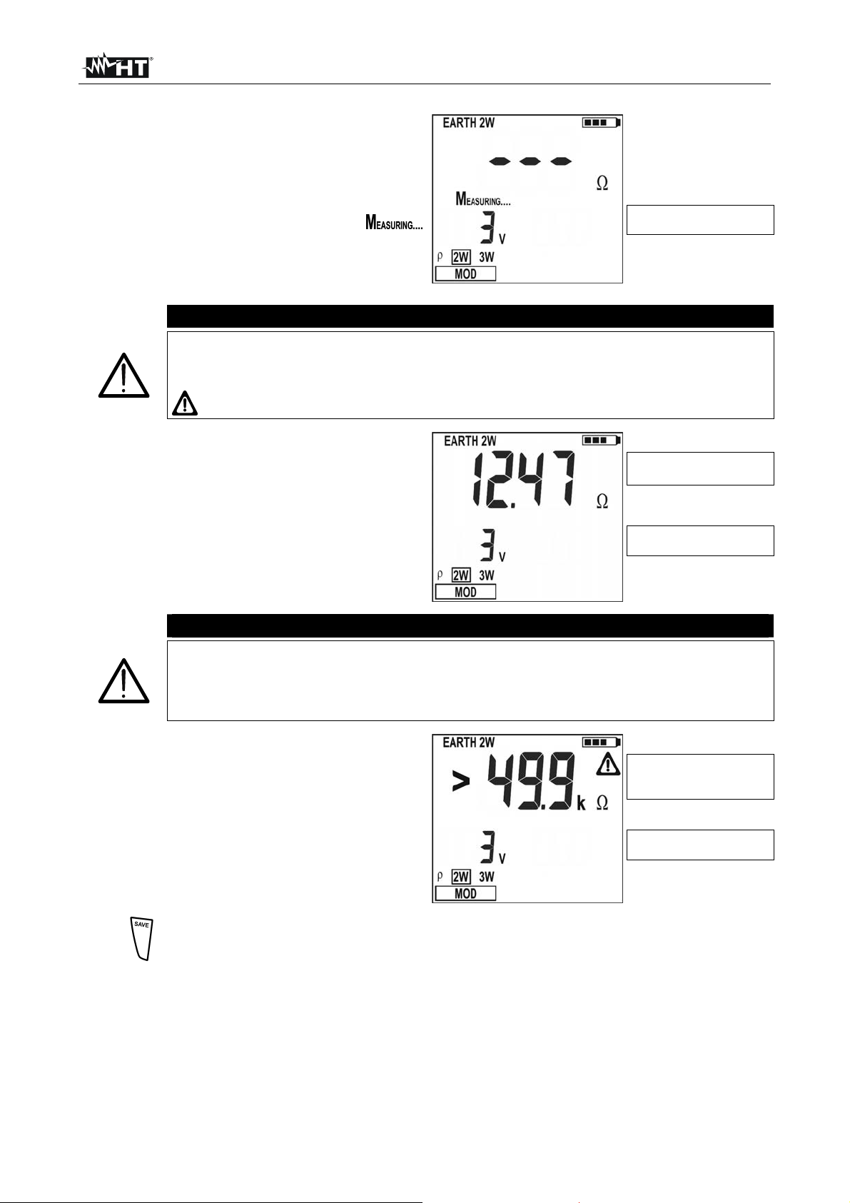
GEO416 - GEO416GS
8. Pendant l'exécution de la mesure de la
part de l'instrument, l'afficheur montre
une page-écran comme celle ci-contre
où l'on trouve la valeur de la tension de
perturbation à l'entrée de l'instrument.
Pendant l'affichage du message
sur l'écran de l'instrument, ne pas
déconnecter ni ne toucher les embouts
de mesure.
ATTENTION
Lors du démarrage de la mesure, on détecte la tension de perturbation à
l'entrée du circuit voltmétrique et du circuit ampérométrique. Si elle est
comprise entre 3V et 9V, l'instrument exécute la mesure et affiche le symbole
pour signaler la décadence de l'incertitude de la mesure (§ 9.1).
9. A la fin de l'essai, si la mesure de la
résistance de terre résulte inférieure à
la fin d'échelle, l'instrument émet un
double signal sonore pour indiquer le
résultat positif de l'essai et montre la
mesure de la résistance et la valeur de
la tension de perturbation présente lors
de la mesure.
ATTENTION
La mesure de la résistance est effectuée avec méthode volt-ampérométrique
à 4 fils qui n'est pas influencée par la valeur de la résistance des câbles
utilisés. Il n'est donc pas nécessaire d'exécuter la compensation de la
résistance des câbles ou de leurs rallonges éventuelles.
10. A la fin de l'essai, si la mesure de la
résistance de terre résulte supérieure à
la fin d'échelle, l'instrument émet un
signal sonore prolongé pour indiquer le
résultat négatif de l'essai et montre la
page-écran ci-contre.
Valeur de la tension de
perturbation à l'entrée
Mesure de la résistance
de terre
Valeur de la tension de
perturbation à l'entrée
Mesure de la résistance
de terre supérieure à la fin
d'échelle
Valeur de la tension de
perturbation à l'entrée
11.
Les mesures peuvent être mémorisées en appuyant deux fois sur la touche
SAVE (§ 5.1).
FR - 11
Page 97

GEO416 - GEO416GS
4.5. - MESURE DE LA RESISTIVITE DU SOL
La valeur de résistivité du sol est un paramètre indispensable pour calculer la valeur de
résistance des électrodes de mise à la terre que l'on utilisera pour réaliser l'installation de
terre. La mesure est exécutée conformément à la réglementation VDE 0413,
IEC/EN61557-5.
ATTENTION
L'instrument peut être utilisé sur des installations en catégorie de
surtension CAT III 240V à la terre avec une tension maximale de 415V
entre les entrées. Ne pas connecter l'instrument à des installations avec
des tensions excédant les limites indiquées dans ce manuel. Le
dépassement de ces limites pourrait entraîner des chocs électriques pour
l'utilisateur et endommager l’instrument
La connexion des câbles de mesure à l'instrument et aux crocodiles doit
toujours se faire avec les accessoires déconnectés de l'installation
Nous vous recommandons de tenir la pince crocodile en respectant la
zone de sécurité prévue pour la protection des mains (voir § 4.2)
Si la longueur des câbles fournis de dotation avec l'instrument n'est pas
appropriée pour les mesures à effectuer (voir § 11), il est possible de
fabriquer des rallonges en adoptant les mesures décrites à la § 11.2.1.
1.
2.
Allumer l'instrument en appuyant sur la touche d'allumage.
En appuyant sur les touches fléchées , sélectionner MOD, ensuite en
appuyant sur les touches fléchées , sélectionner la fonction .
Fig. 6 : Mesure de la résistivité du sol
FR - 12
Page 98

GEO416 - GEO416GS
3. L'afficheur montre une page-écran
comme celle ci-contre où l'on trouve la
valeur de la tension de perturbation à
l'entrée de l'instrument et la valeur de la
distance sélectionnée entre les
électrodes de mise à la terre.
Valeur de la tension de
perturbation à l'entrée et
de la distance réglée entre
les électrodes de mise à la
terre
Si l'on souhaite modifier la
4.
distance entre les électrodes de
mise à la terre, appuyer sur les
touches fléchées , et
sélectionner DIST, appuyer
ensuite sur les touches fléchées
, pour régler la distance
Valeur de la distance
sélectionnée entre les
électrodes de mise à la
terre
souhaitée (de un à dix mètres,
par pas de un, ou bien de trois
à trente pieds par pas de trois).
Pour régler l'unité de mesure de
5.
Unité de mesure réglée
la distance, appuyer sur les
touches fléchées , et
sélectionner UNIT, appuyer
ensuite sur les touches fléchées
, pour régler l'unité de
mesure souhaitée (m ou ft).
6. Insérer les câbles de mesure bleu, rouge, vert et noir dans les entrées
correspondantes de l'instrument H, S, ES, E et brancher, si nécessaire, les
crocodiles.
7. Le cas échéant, rallonger les câbles de mesure séparément en utilisant des câbles
ayant une section appropriée. La présence de rallonges éventuelles ne demande
aucune calibration ni ne modifie la valeur de résistivité du sol mesurée.
8. Planter dans le sol quatre électrodes de mise à la terre en ligne et les mettre à une
distance mutuelle égale à ce qui est sélectionné sur l'instrument. Le réglage d'une
distance autre par rapport à celle qui est effectivement présente entre les électrodes
de mise à la terre compromet la mesure (§11.3).
9. Connecter les crocodiles aux électrodes de mise à la terre (voir Fig. 6).
10.
Appuyer sur la touche GO, l'instrument exécute la mesure.
FR - 13
Page 99
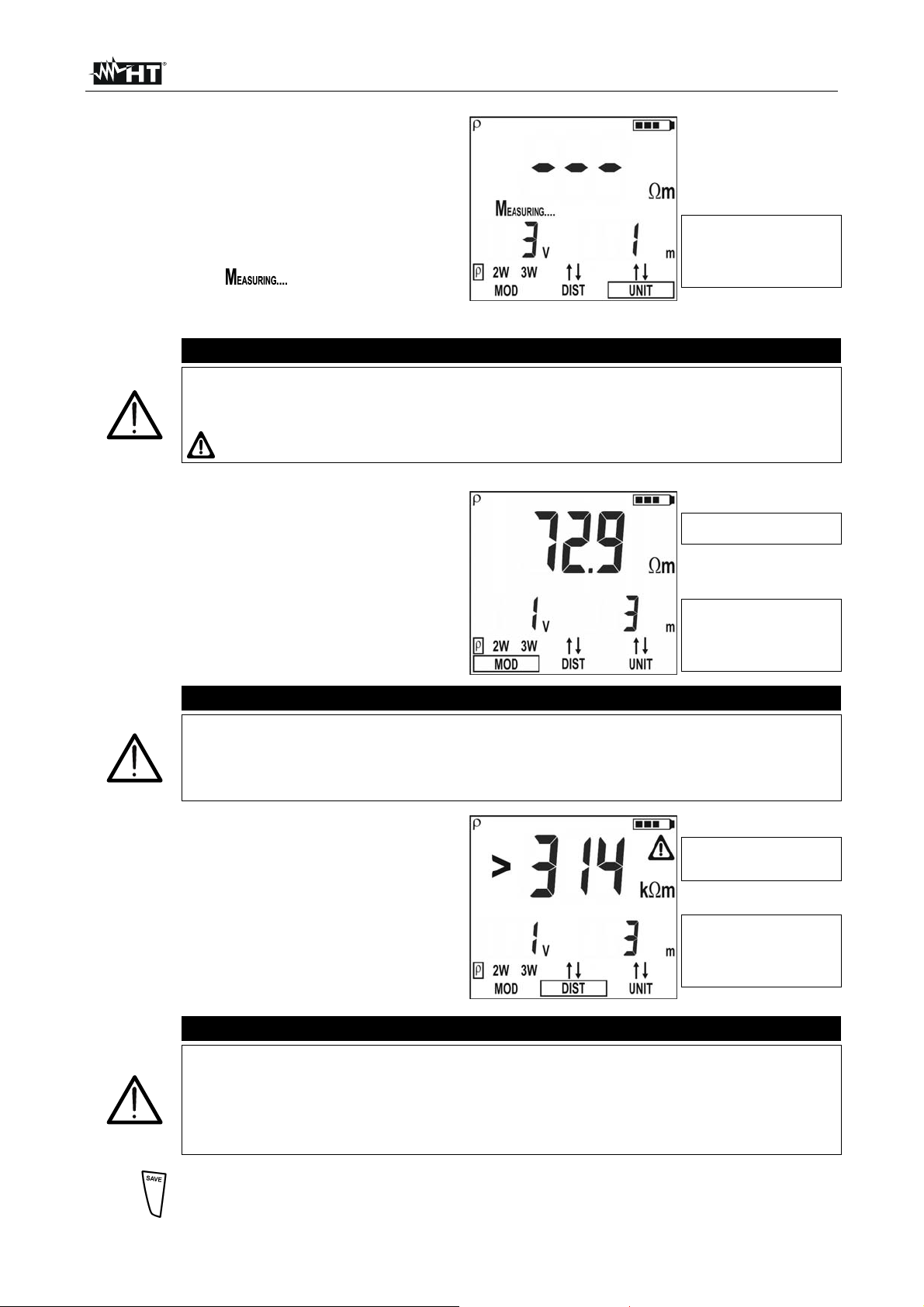
GEO416 - GEO416GS
11. Pendant l'exécution de la mesure de la
part de l'instrument, l'afficheur montre
une page-écran comme celle ci-contre
où l'on trouve la valeur de la tension de
perturbation à l'entrée et la distance
sélectionnée entre les électrodes de
mise à la terre. Pendant l'affichage du
message sur l'écran de
l'instrument, ne pas déconnecter ni ne
toucher les embouts de mesure.
ATTENTION
Lors du démarrage de la mesure, on détecte la tension de perturbation à
l'entrée du circuit voltmétrique et du circuit ampérométrique. Si elle est
comprise entre 3V et 9V, l'instrument exécute la mesure et affiche le symbole
pour signaler la décadence de l'incertitude de la mesure (§ 9.1).
12. A la fin de l'essai, si la mesure de la
résistivité résulte inférieure à la fin
d'échelle, l'instrument émet un double
signal sonore pour indiquer le résultat
positif de l'essai et montre la mesure de
la résistivité et la valeur de la tension de
perturbation présente lors de la mesure.
ATTENTION
La mesure de la résistivité est effectuée avec méthode volt-ampérométrique à
4 fils qui n'est pas influencée par la valeur de la résistance des câbles utilisés.
Il n'est donc pas nécessaire d'exécuter la compensation de la résistance des
câbles ou de leurs rallonges éventuelles.
13. A la fin de l'essai, si la mesure de la
résistivité de terre résulte supérieure à
la fin d'échelle, l'instrument émet un
signal sonore prolongé pour indiquer le
résultat négatif de l'essai et montre la
page-écran ci-contre.
ATTENTION
La fin d'échelle est calculée en tant que ρ
= 2 DIST R où DIST est la
MAX
valeur réglée de la distance entre les électrodes de mise à la terre et R est la
valeur maximum de résistance pouvant être mesurée par l'instrument. La fin
d'échelle de la mesure de résistivité de terre dépend donc du réglage de la
distance entre les électrodes de mise à la terre.
14.
Les mesures peuvent être mémorisées en appuyant deux fois sur la touche
SAVE (§ 5.1).
Valeur de la tension de
perturbation à l'entrée et
de la distance réglée entre
les électrodes de mise à la
terre
Mesure de la résistivité du
sol
Valeur de la tension de
perturbation à l'entrée et
de la distance réglée entre
les électrodes de mise à la
terre
Mesure de la résistivité du
sol supérieure à la fin
d'échelle
Valeur de la tension de
perturbation à l'entrée et
de la distance réglée entre
les électrodes de mise à la
terre
FR - 14
Page 100

GEO416 - GEO416GS
4.5.1. Situations d'anomalies pour les mesures
1. Au démarrage de la mesure,
l'instrument vérifie la continuité des
câbles de mesure. Si le circuit
voltmétrique (câbles rouge S et vert
ES) est interrompu ou a une
résistance trop élevée, l'instrument
affiche une page-écran comme celle cicontre. Contrôler que les bornes sont
connectées correctement et que
l'électrode de mise à la terre branchée
terrain caillouteux ou peu conducteur. Si cela est le cas verser de l'eau autour de
sur la borne S n'est pas plantée dans un
Résistance du circuit
voltmétrique trop élevée
Valeur de la tension de
perturbation à l'entrée
Exemple en mode 3W
l'électrode de mise à la terre pour diminuer sa résistance (§ 11.2). Affiche RP>top si:
Au circuit voltmétrique on ajoute une résistance de l'électrode S RS > 50KΩ
La résistance de l'électrode S dépasse la valeur 1200 + 100 RX [Ω] (où RX est la
valeur mesurée de la résistance de terre)
2. Au démarrage de la mesure,
l'instrument vérifie la continuité des
câbles de mesure. Si le circuit
ampérométrique (câbles bleu H et
Résistance du circuit
ampérométrique trop
élevée
noir E) est interrompu ou a une
résistance trop élevée, l'instrument
affiche une page-écran comme celle cicontre. Contrôler que les bornes sont
connectées correctement et que
Valeur de la tension de
perturbation à l'entrée
Exemple en mode 3W
l'électrode de mise à la terre branchée sur la borne H n'est pas plantée dans un
terrain caillouteux ou peu conducteur, si cela est le cas verser de l'eau autour de
l'électrode de mise à la terre pour diminuer sa résistance (§ 11.2). Affiche RC>top :
Au circuit ampérométrique on ajoute une résistance de l'électrode H RH> 50KΩ
La résistance de l'électrode H dépasse la valeur 1200 + 100 RX [Ω] (où RX est la
valeur mesurée de la résistance de terre)
3. Au démarrage de la mesure,
l'instrument vérifie la continuité des
câbles de mesure. Si le circuit
voltmétrique (câbles rouge S et vert
ES) et le circuit ampérométrique
(câbles bleu H et noir E) sont
interrompus tous les deux ou ont
une résistance trop élevée,
l'instrument affiche une page-écran
comme celle ci-contre. Contrôler
que les bornes sont connectées
Résistances du circuit
voltmétrique et du circuit
ampérométrique trop
élevées
Valeur de la tension de
perturbation à l'entrée
Exemple en mode 3W
correctement et que les électrodes de mise à la terre branchées sur les bornes S et H
ne sont pas plantées dans un terrain caillouteux ou peu conducteur ; si cela est le cas
verser de l'eau autour des électrodes de mise à la terre pour diminuer leur résistance
(§ 11.2). On affiche RP, RC>top si :
Au circuit voltmétrique on ajoute une résistance de l'électrode S RS > 50KΩ et au
circuit ampérométrique on ajoute une résistance de l'électrode H RH > 50KΩ
La résistance de l'électrode S et la résistance de l'électrode H dépassent toutes
les deux la valeur 1200 + 100 RX [Ω] (où RX est la valeur mesurée de la résistance
de terre
FR - 15
 Loading...