

Page 1
3
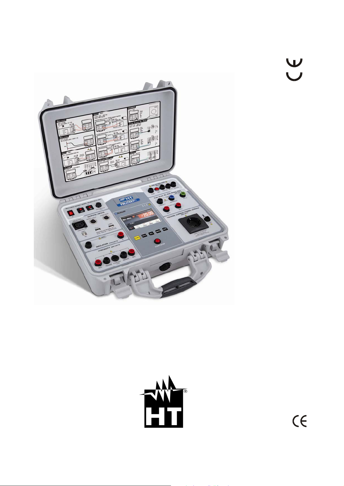
FULLTEST
User’s manual
Copyright HT ITALIA 2014 Release EN 1.01 - 24/01/2014
Page 2

FULLTEST 3
Table of contents:
1. SAFETYPRECAUTIONSANDPROCEDURES.............................................................................................3
1.1. PRELIMINARYINSTRUCTIONS...................................................................................................... 4
1.2. DURINGUSE................................................................................................................................4
1.3. AFTERUSE...................................................................................................................................5
1.4. OVERVOLTAGECATEGORIES‐DEFINITIONS..................................................................................5
2. GENERALDESCRIPTION.........................................................................................................................6
2.1. WORKING....................................................................................................................................6
2.2. OPENINGTHEINSTRUMENT'SCOVER...........................................................................................8
3. PREPARATIONFORUSE........................................................................................................................9
3.1. PRELIMINARYCHECKS..................................................................................................................9
3.2. POWERSUPPLY...........................................................................................................................9
3.3. CALIBRATION...............................................................................................................................9
3.4. TRANSPORTANDSTORAGE..........................................................................................................9
4. OPERATINGINSTRUCTIONS................................................................................................................10
4.1. INSTRUMENT‐DESCRIPTION.....................................................................................................10
4.2. TURNINGONTHETESTER..........................................................................................................11
4.3. MEASUREMENTFUNCTIONSELECTION......................................................................................12
5. MEASUREMENTS................................................................................................................................13
5.1. CONTINUITY‐TWOWIREMETHOD(RPE‐2WIRE)........................................................................13
5.1.1. RPE‐2WIREDISPLAYEXPLANATION...............................................................................................13
5.1.2. CALIBRATIONOFTESTLEADS........................................................................................................14
5.1.3. LIMITVALUEADJUSTMENT...........................................................................................................15
5.1.4. RPE‐2WIREMEASUREMENT..........................................................................................................16
5.2. CONTINUITY‐FOURWIREMETHOD(RPE‐4WIRE).......................................................................18
5.2.1. RPE‐4WIREDISPLAYEXPLANATION...............................................................................................18
5.2.2. CALIBRATIONOFTESTLEADS........................................................................................................19
5.2.3. RPE‐4WIREMEASUREMENT..........................................................................................................20
5.3. INSULATIONRESISTANCE(M)..................................................................................................22
5.3.1. RISODISPLAYEXPLANATION.........................................................................................................22
5.3.2. RISOMEASUREMENT....................................................................................................................23
5.4. DIELECTRIC(DIELECTRIC)............................................................................................................25
5.4.1. WARNINGS....................................................................................................................................25
5.4.2. DIELECTRICDISPLAYEXPLANATION..............................................................................................26
5.4.3. DIELECTRICTEST............................................................................................................................27
5.5. RCD(RCD)..................................................................................................................................29
5.5.1. RCDDISPLAYEXPLANATION..........................................................................................................29
5.5.2. EXPLANATIONOFRCDTESTCURRENTS........................................................................................30
5.5.3. RCDMEASUREMENT.....................................................................................................................31
5.6. LOOPIMPEDANCE/SHORT‐CIRCUITCURRENT(LOOP)...............................................................33
5.6.1. LOOPDISPLAYEXPLANATION........................................................................................................33
5.6.2. LIMITVALUEEXPLANATION..........................................................................................................34
5.6.3. PROSPECTIVESHORT‐CIRCUITCURRENTCALCULATION...............................................................35
5.6.4. LOOPMEASUREMENT...................................................................................................................36
5.7. GLOBALEARTHRESISTANCE/CONTACTVOLTAGE(RA)..............................................................39
5.7.1. RALIMITVALUECALCULATION.....................................................................................................39
5.7.2. RADISPLAYEXPLANATION............................................................................................................39
5.7.3. RAMEASUREMENT.......................................................................................................................40
5.8. RESIDUALVOLTAGE(URES)........................................................................................................42
5.8.1. EXPLANATIONOFLINEARMODE..................................................................................................42
5.8.2. EXPLANATIONOFNONLINEAR MODE...........................................................................................43
5.8.3. URESDISPLAYEXPLANATION........................................................................................................44
5.8.4. TRIGGERCONDITIONS...................................................................................................................44
5.8.5. URESMEASUREMENT...................................................................................................................45
5.9. POWER(POWER).......................................................................................................................48
5.9.1. POWERDISPLAYEXPLANATION....................................................................................................48
5.9.2. POWERMEASUREMENT...............................................................................................................49
5.10. PHASESEQUENCE(PHASESEQ)...................................................................................................51
EN - 1
Page 3

FULLTEST 3
5.10.1. PHASESEQUENCEDISPLAYEXPLANATION...............................................................................51
5.10.2. PHASESEQUENCEMEASUREMENT..........................................................................................52
5.11. CURRENTMEASUREMENTUSINGCURRENTCLAMP(ICLAMP)....................................................53
5.11.1. ICLAMPDISPLAYEXPLANATION...............................................................................................53
5.11.2. ICLAMPMEASUREMENT..........................................................................................................54
5.12. LEAKAGECURRENT(ILEAK)........................................................................................................55
5.12.1. LEAKAGEDISPLAYEXPLANATION.............................................................................................55
5.12.2. LEAKAGECURRENTMEASUREMENTUSINGCURRENTCLAMP................................................57
5.12.3. LEAKAGECURRENTMEASUREMENTONSCHUKOSOCKET......................................................58
6. MENUFUNCTIONS..............................................................................................................................60
6.1. MEMORYmenu.........................................................................................................................60
6.1.1. MEMORYINFOmenu....................................................................................................................60
6.1.2. CLEARmenu..................................................................................................................................61
6.1.3. USBmenu......................................................................................................................................61
6.2. SELECTOPERATORmenu...........................................................................................................61
6.3. LANGUAGEmenu...................................................................................................................... 62
6.4. TESTERINFOmenu....................................................................................................................62
6.5. SETUPmenu..............................................................................................................................63
6.5.1. LEVELNAMESmenu......................................................................................................................63
6.5.2. LIMITCONTACTVOLTAGEmenu...................................................................................................64
6.5.3. DATE/TIMEmenu..........................................................................................................................64
6.5.4. RESETmenu...................................................................................................................................64
6.5.5. NOMINALVOLTAGEmenu............................................................................................................69
6.5.6. SAFETYmenu.................................................................................................................................69
6.6. SOUNDmenu.............................................................................................................................70
7. MEMORYFEATURES...........................................................................................................................71
7.1. MEMORYSTRUCTURE................................................................................................................71
8. MEMORIZINGEXAMPLE.....................................................................................................................72
9. RECALLRESULTS.................................................................................................................................74
10. ENTRYOFDATABYUSINGANEXTERNALKEYBOARD..........................................................................76
11. ENTRYOFDATAUSINGABARCODEREADER....................................................................................... 76
12. FWUPDATEOFTHEFULLTEST3..........................................................................................................76
13. MAINTENANCE...................................................................................................................................76
13.1. CLEANING..................................................................................................................................76
13.2. FUSEREPLACEMENT..................................................................................................................76
14. TECHNICALSPECIFICATIONS................................................................................................................78
14.1. MEASUREMENTFUNCTIONS......................................................................................................78
14.2. GENERALSPECIFICATION...........................................................................................................89
14.3. ACCESSORIES.............................................................................................................................89
15. SERVICE..............................................................................................................................................90
15.1. WARRANTYCONDITIONS...........................................................................................................90
15.2. AFTER‐SALESERVICE..................................................................................................................90
EN - 2
Page 4
FULLTEST 3
1. SAFETY PRECAUTIONS AND PROCEDURES
CAUTION
For your own safety and to avoid damaging the instrument follow the procedures
described in this instruction manual and read carefully all notes marked with this symbol.
This instrument complies with safety Standards EN61557 and EN61010-1 related to electronic
measuring instruments. When taking measurements:
Avoid doing this in humid or wet places - make sure that humidity is within the limits indicated in
section “Environmental conditions”.
Avoid doing this in rooms where explosive gas, combustible gas, steam or excessive dust is
present.
Keep you insulated from and do not touch the object under test, any exposed metal part such as
test lead ends, sockets, fixing objects, circuits etc.
Avoid doing this if you notice anomalous conditions such as breakages, deformations, fractures,
blind display etc.
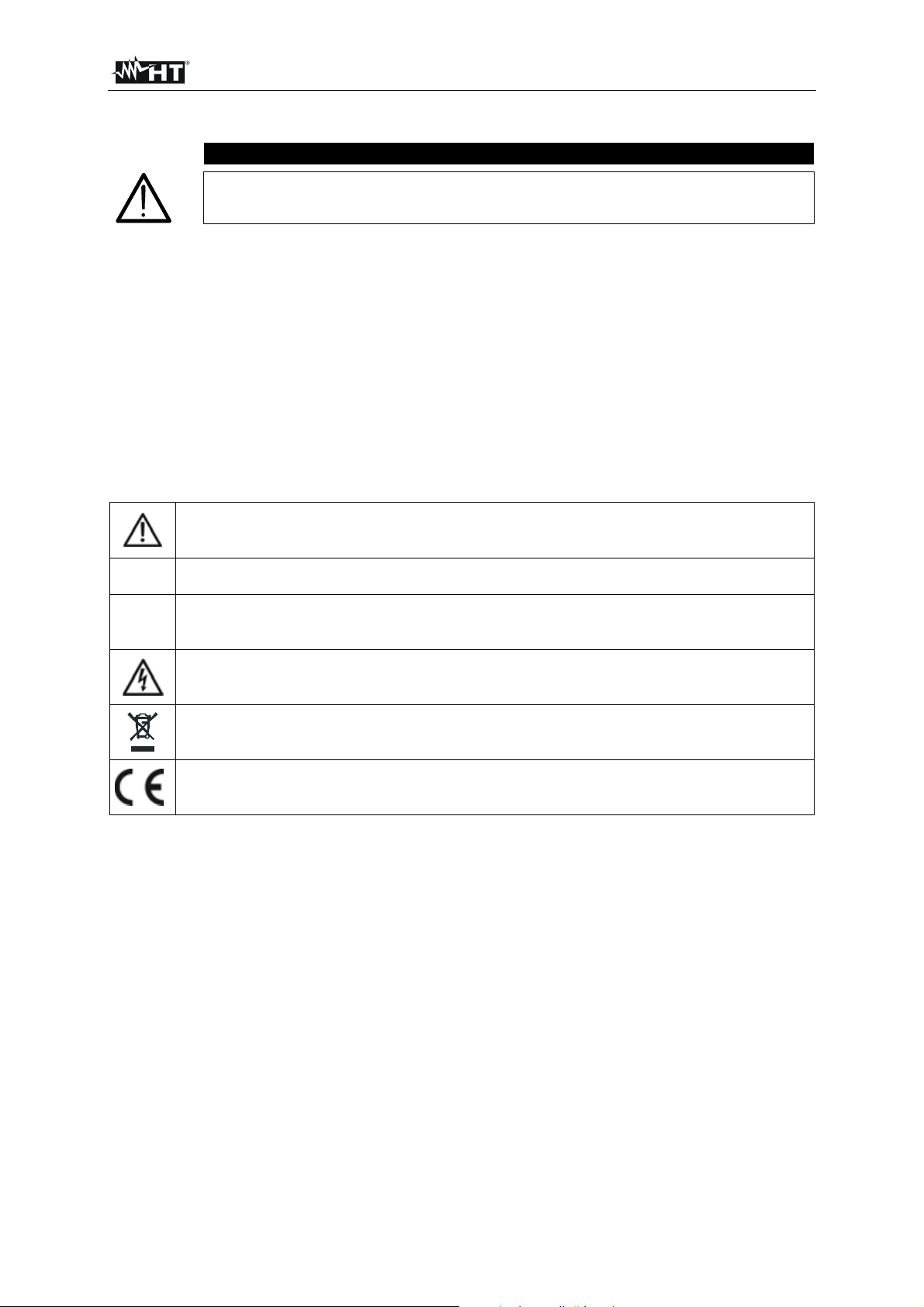
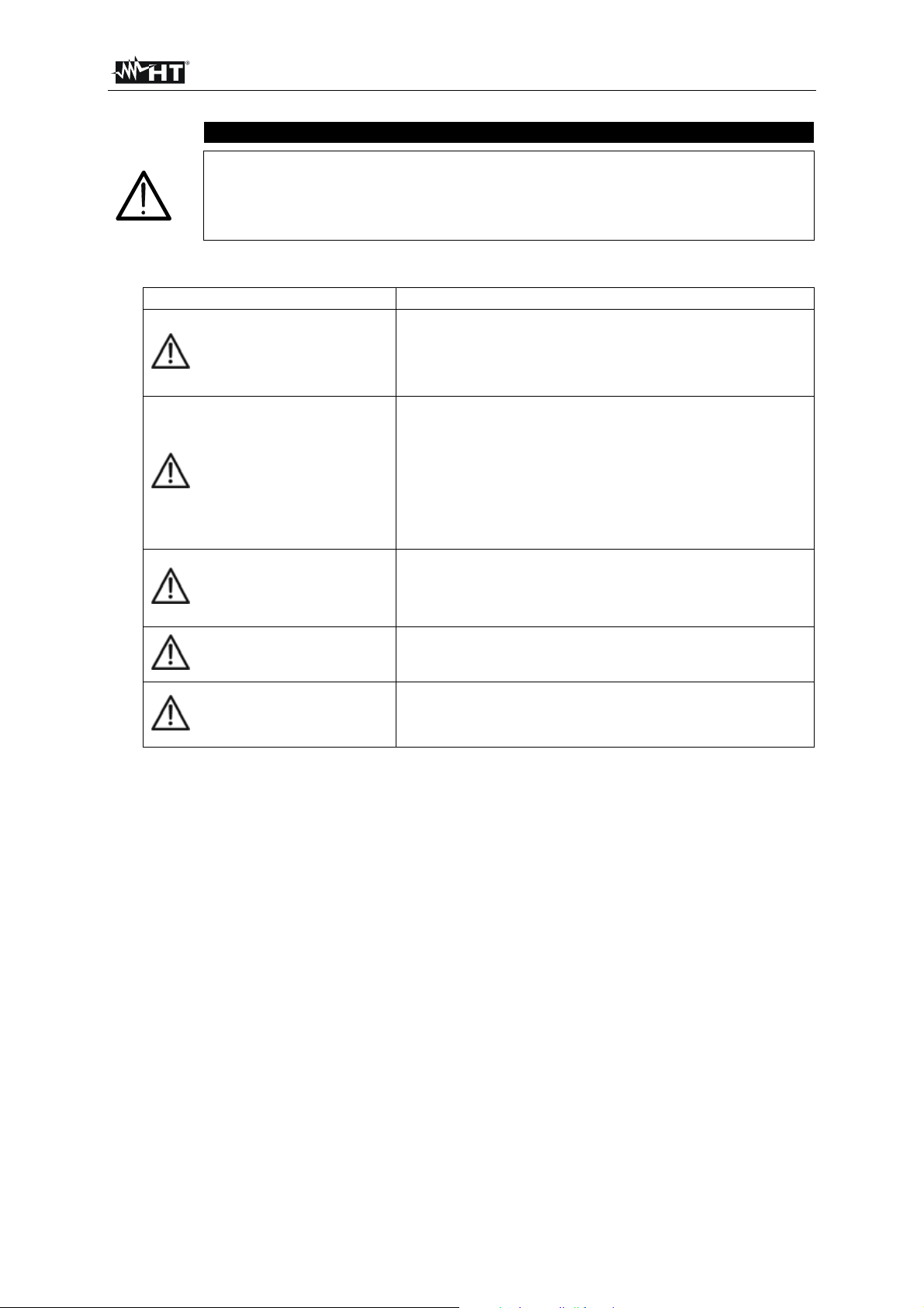
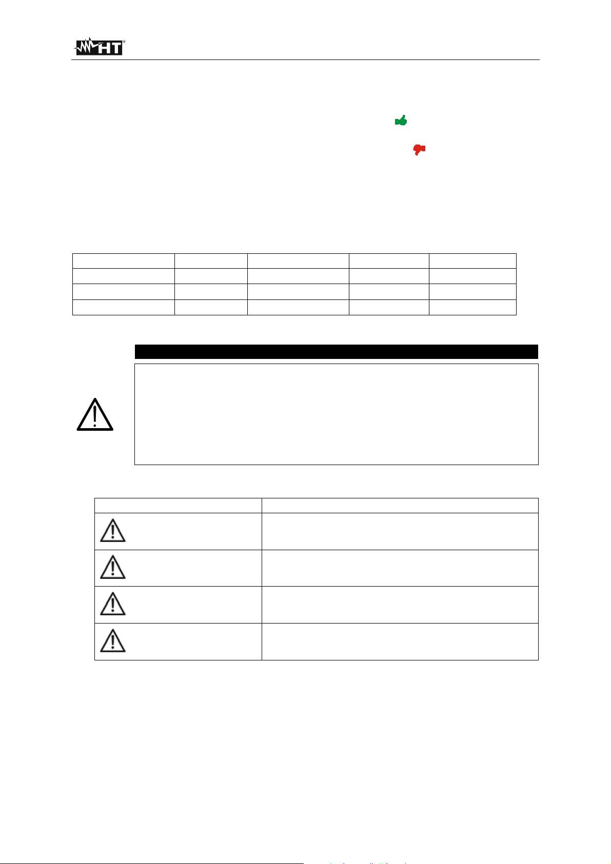
The following symbols are used in this instruction manual:
Warning of a potential danger, comply with instruction manual.
☞
Reference, please pay utmost attention.
UUT Unit under test
Caution, dangerous voltage. Danger of electrical shock.
Symbol for marking of electrical and electronic equipment (WEEE Directive).
Conformity symbol, the instrument complies with the valid directives. It complies with the
EMC Directive and the Low Voltage Directive.
EN - 3
Page 5
FULLTEST 3
1.1. PRELIMINARY INSTRUCTIONS
CAUTION
The instrument must be connected to a power socket with grounded PE terminal. If this
is not assured, the instrument will display PE DISCONNECTED, SWITCH OFF NOW
message and will perform no measurement.
The instruction manual contains information and references, necessary for safe operation and
maintenance of the instrument. Prior to using the instrument, the user is kindly requested to
thoroughly read the instruction manual and comply with it in all sections.
Failure to read the instruction manual or to comply with the warnings and references contained
herein can result in serious bodily injury or instrument damage.
In order to avoid electrical shock, the valid safety and national regulations regarding excessive
contact voltages must receive utmost attention when working with voltages exceeding 60 V DC or
50 V (25 V) RMS AC. The value in brackets is valid for limited ranges (as for example medicine).
The operator is recommended to respect the usual safety regulations aimed at protecting against
dangerous currents and protecting the instrument against improper use.
This instrument has been designed for use in environments of pollution degree 2.
It can be used for tests on electrical installations of overvoltage category III, 300V maximum
voltage to earth.
Do not effect measurements on circuit exceeding the specified voltage limits.
Only the original test leads supplied along with the instrument guarantee compliance with the
safety standards in force. They must be in good conditions and, if necessary, replaced with
identical ones.
Do not take measurements under environmental conditions exceeding the limits indicated in this
manual.
Before connecting the test probes to the installation make sure that the right function is selected.
The instrument may only be used in dry and clean environments. Dirt and humidity reduce
insulation resistance and may lead to electrical shocks, in particular for high voltages.
Never use the instrument in precipitation such as dew or rain. In case of condensation due to
temperature jumps, the instrument may not be used.
Start any test series by earth bond resistance measurement.
At earth bond resistance, insulation resistance and dielectric measurements unit under test must
be voltage-free. If necessary check the unit is voltage-free i.e. by using a voltage tester.
When modifying the instrument, the operational safety is no longer ensured.
1.2. DURING USE
CAUTION
An improper use may damage the instrument and/or its components or injure the
operator.
Only skilled technicians, who know the possible risks involved to the dangerous voltages use are
allowed to operate the instrument.
The instrument may only be connected to mains voltage as indicated on the type shield.
The instrument may only be used within the operating ranges as specified in the technical data
section.
Disconnect the test leads from the circuit under test before selecting any function.
Only touch test leads and test probes at handle surface provided. Never directly touch test probes.
Never touch any unused terminal when the instrument is connected to circuits.
EN - 4
Page 6

FULLTEST 3
Do not measure resistance in presence of external voltages; although the instrument is protected,
an excessive voltage may cause malfunctioning.
Do not open the instrument! Dangerous voltages inside!
Connecting one terminal to the test object and working with one probe or holding both probes in
one hand is prohibited.
Use safety probes with protection against contact or with two-hand operation only. Always hold
only one probe in one hand.
It is prohibited to touch the unit under test during the test. If need be, additional measures must be
taken (e.g. cover made of insulating mats) to protect the person performing the test against
inadvertent contact with the unit under test.
1.3. AFTER USE
Disconnect all test leads from the circuit under test and switch off the instrument.
1.4. OVERVOLTAGE CATEGORIES - DEFINITIONS
Standard EN61010-1 (Safety requirements for electrical equipment for measurement, control and
laboratory use, Part 1: General requirements) defines what a measurement category (usually called as
Overvoltage Category) is. At paragraph 6.7.4: Measuring circuits it says:
(OMISSIS)
Circuits are divided into the following measurement categories:
Measurement category IV is for measurements performed at the source of the low-voltage
installation.
Examples are electricity meters and measurements on primary overcurrent protection devices
and ripple control units.
Measurement category III is for measurements performed in the building installation.
Examples are measurements on distribution boards, circuit breakers, wiring, including cables,
bus-bars, junction boxes, switches, socket-outlets in the fixed installation, and equipment for
industrial use and some other equipment, for example, stationary motors with permanent
connection to fixed installation.
Measurement category II is for measurements performed on circuits directly connected to the
low voltage installation.
Examples are measurements on household appliances, portable tools and similar equipment.
Measurement category I is for measurements performed on circuits not directly connected to
MAINS.
Examples are measurements on circuits not derived from MAINS, and specially protected
(internal) MAINS-derived circuits. In the latter case, transient stresses are variable; for that
reason, the norm requires that the transient withstand capability of the equipment is made
known to the user.
EN - 5
Page 7
FULLTEST 3
2. GENERAL DESCRIPTION
Dear Customer, the instrument you have purchased, whether used according to the instructions given in
this manual, will grant you accurate and reliable measurements. Thanks to a development of newest
conception assuring overvoltage category III you will enjoy the highest safety.
The Machinery Tester FULLTEST 3 is a measurement instrument used for final inspection of electrical
equipment of machines, control cabinets, switchgears as well as other devices complying with
IEC/EN60204-1 and IEC/EN61439-1 standards.
2.1. WORKING
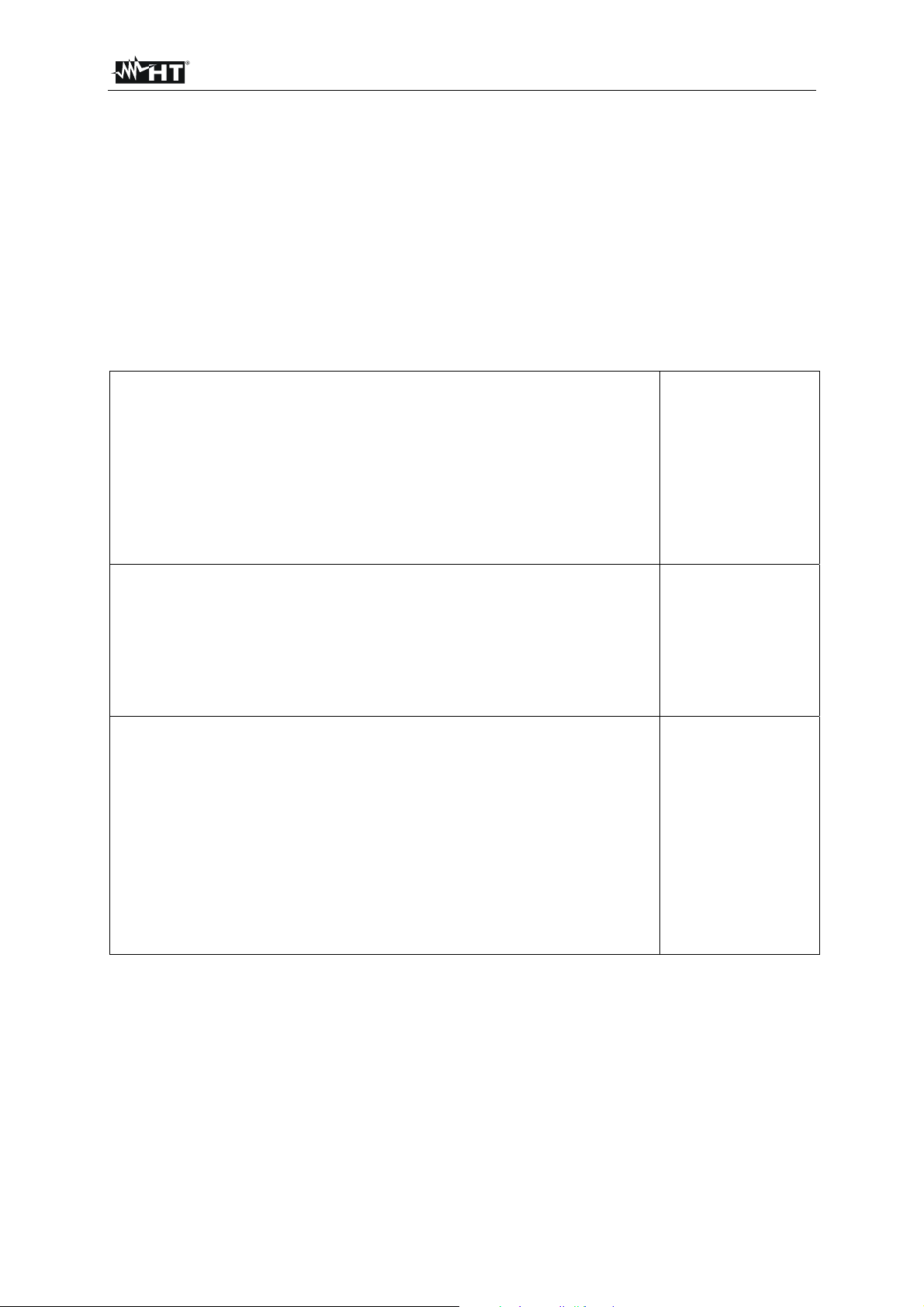
The instrument can carry out the following tests, further to the regulations listed below:
Continuity of protective conductor
- 2-wire or 4-wire measurement method.
- Compensation of test leads in case of 2-wire measurement.
- Open-circuit test voltage 6 V approx.
- Test current 200 mA and 25 A.
- Limit value adjustable, visual and acoustic warning in case of exceeded
value.
EN61557-4
EN61439-1-§10.5.2
EN60204-1-§18.2.2
EN60598-1
EN60335-1-§27.5
EN60335-1-§A.1
EN50106
EN60950
CEI 64-8/7-CEI64/13
Insulation resistance
- Test voltage 100 V, 250 V, 500 V and 1000 V DC.
- MAN (manual) mode.
- TIMER mode.
- AUTO mode.
- Limit value adjustable, visual and acoustic warning in case of exceeded
value.
Dielectric test
- Adjustable test voltage 250 V up to 5100 V AC.
- Trip out current adjustable 1 110 mA, visual and acoustic warning in
case of exceeded limit value.
- Display and trip out based on real or apparent current.
EN61557-2
CEI64-8
CEI23-51
CEI64-8/7-CEI64/13
EN61439-1-§11.9
EN60204-1
EN60598-1
EN61439-1-§9.1
EN60204-1-§18.4
EN60598-1
EN60335-1-§13.3
EN60335-1-§A.2
- MANUAL mode.
- RAMP mode (predefined automatic rising of test voltage).
- BURN mode.
- Protection against unauthorised use (safety measure).
- Red warning lamp connector (safety measure).
- Safety input connector (safety measure).
EN - 6
Page 8
FULLTEST 3
RCD test
- AC, A and B type.
- General, selective and delayed characteristic.
- Voltage range 100 ... 265 V.
- Limit contact voltage 25 or 50 V.
- IN = 10, 30, 100, 300, 500, 650 or 1000 mA.
- Trip out time at IN/2 (AC, A and B type).
- Trip out time at IN (AC, A and B type).
- Trip out time at 2IN (AC and A type).
- Trip out time at 5IN (AC and A type) or at 4IN (B type).
- Ramp test (AC, A and B type).
- AUTO test (AC, A and B type).
- Visual and acoustic warning in case of exceeded limit value.
Loop impedance measurement
- ZL/N, ZL/L and ZL/PE measurement.
- Voltage range 100 460 V.
- IPSC calculation.
- Limit value adjustable, visual and acoustic warning in case of exceeded
value.
Global earth resistance
- Selectable test current with regard to involved RCD.
- IN = 10, 30, 100, 300, 500, 650 or 1000 mA.
- Measurement with IN/2 (without tripping out RCD)
- Voltage range 100 265 V.
- Contact voltage UC measured during the measurement.
- Limit value (RA) fixed to 25 or 50 V/IN, visual and acoustic warning in
case of exceeded value.
Residual voltage
- Measurement on power plug (2-wire method).
- Measurement on internal components (4-wire method).
- Limit discharge time 1 s or 5 s.
- LINEAR or NONLINEAR mode.
- Visual and acoustic warning in case of exceeded limit value.
Power (on schuko socket)
- Apparent power P
APP.
- Real power P.
- Mains voltage U
L/N.
- Load current IL.
- Power factor PF.
- Leakage current IPE (differential method).
- Internal phase position exchange.
- Limit value (apparent power) adjustable, visual and acoustic warning in
case of exceeded value.
Phase sequence
- Mains voltages UL1/2, UL2/3, UL3/1 simultaneously displayed.
EN61557-6
EN60204-1-§18.2
EN61557-3
EN60204-1-§18.5
EN61557-7
EN - 7
Page 9
FULLTEST 3
Clamp current
- Measurement in combination with HT96U current clamp.
- Three ranges 1 A, 100 A and 1000 A.
- Limit value adjustable, visual and acoustic warning in case of exceeded
value.
Leakage current
- Measurement of IPE current on schuko socket (differential method).
- Measurement with current clamp type HT96U, three ranges 1 A, 100 A
and 1000 A.
- Limit value adjustable, visual and acoustic warning in case of exceeded
value.
GENERAL advantages
- Portable Machinery & Panel Tester constructed according to the
IEC/EN60204-1 and IEC/EN61439-1 standards.
- Operation system WINDOWS EMBEDDED COMPACT 7 supports all
measurements and operations.
- Easy and clear operation by using the touch screen and intuitive hard
keys.
- TRMS measurements.
- Data memory for 999 measurement results, three levels (e.g.
CUSTOMER, LOCATION, MACHINE) plus additional COMMENT.
- Real time clock included.
- Integrated interface (USB 2.0) for transfer of measurement results to PC.
- Separate interface (USB 2.0) for connection of USB barcode reader, USB
keyboard, USB memory stick, printer or IMP57-impedance tester.
- Graphic colour touch screen 102×60 mm, 480×272 dots.
- Compact housing with external accessory bag.
- Quick connection diagrams and limit values under the instrument cover.
- Fuse protection in case of overload.
- PC Software TOP VIEW available.
- Complete test accessories included.
- Blue tooth communication.
- Remote START/STOP and SAVE function.
- *HELP screens available.
- *20 programmable AUTO test procedures.
* Special FW version.
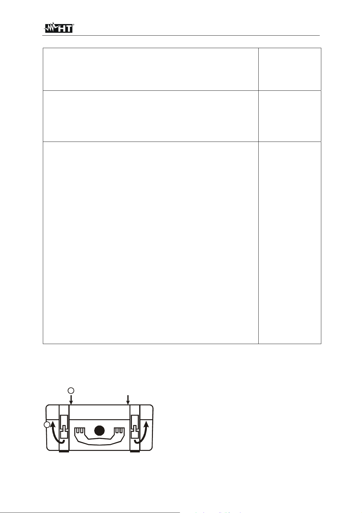
2.2. OPENING THE INSTRUMENT'S COVER
The instrument is built in a robust plastic case that allows comfortable transport.
We recommend the user to follow the next opening instructions:
1
Place the unit on to a hard horizontal surface.
2
Press on the case cover with your hands, see the
mark 1.
Unlock the fixing hooks of the cover, see the mark 2.
Open the cover into vertical position.
Figure 1: Opening the instrument’s cover
EN - 8
Page 10

FULLTEST 3
3. PREPARATION FOR USE
3.1. PRELIMINARY CHECKS
This instrument was checked both mechanically and electrically prior to shipment. All possible cares and
precautions were taken to let you receive the instrument under perfect conditions. Notwithstanding we
suggest you to check it rapidly (possible damages may have occurred during transport – if so please
contact the local distributor from whom you purchased the item).
Make sure all standard accessories according to Packing List are included.
Should you have to return back the instrument for any reason please follow the instructions mentioned
in paragraph “TRANSPORT AND STORAGE”.
3.2. POWER SUPPLY
Earthed plugs must energize the instrument. To avoid any risk the instrument does not allow to effect
measurements when there is not such a connection (refer to paragraph “TURNING ON THE TESTER”
for details).
3.3. CALIBRATION
The instrument complies with the technical specifications contained in this manual and such a
compliance is guaranteed for 1 year. Annual recalibration is recommended.
3.4. TRANSPORT AND STORAGE
Please keep the original packaging for potential later transport, e.g. for calibration. Any transport
damage due to faulty packaging will be excluded from warranty claims.
Instruments must be stored in dry and closed areas. In case of an instrument being transported in
extreme temperatures, a recovery time of minimum 2 hours is required prior to instrument operation.
EN - 9
Page 11
FULLTEST 3
4. OPERATING INSTRUCTIONS
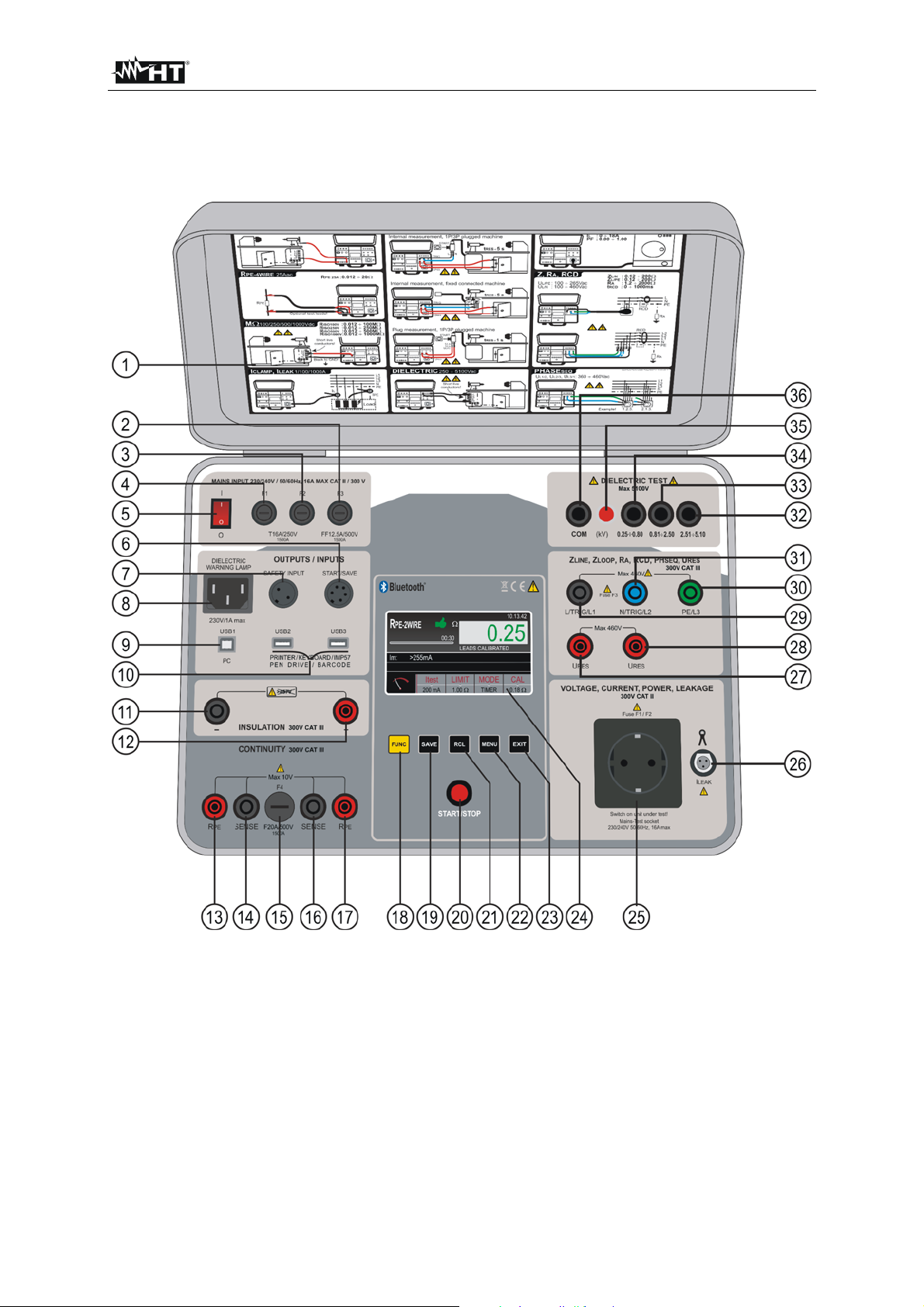
4.1. INSTRUMENT - DESCRIPTION
Figure 2: Instrument description
LEGEND
1 Quick instruction label under the cover.
2 Fuse F3, type T12.5A/500V 6.3×32 mm which protects internal circuitry in LOOP, RA and RCD
measurements.
3 General tester fuse F2, type T16A/250V 5×20 mm which protects internal circuitry in POWER, RPE
and DIELECTRIC measurements.
4 General tester fuse F1, type T16A/250V 5×20 mm which protects internal circuitry in POWER, RPE
and DIELECTRIC measurements.
5 ON/OFF mains switch (with red pilot lamp).
EN - 10
Page 12

FULLTEST 3
6 Connector for START/SAVE remote control adapter.
7 Connector SAFETY INPUT for connection of external safety switch (for example protection door). It
disables DIELECTRIC tests in case the switch is open.
8 IEC female connector for connection of red WARNING LAMP in DIELECTRIC test. The lamp is
active when the test is on (parallel operation to HV lamp on front panel, reference 35).
9 USB 1 connector for connection with PC.
10 USB 2 and USB 3 connectors for connection of USB stick, USB barcode reader, USB printer, USB
keyboard or IMP57 impedance meter.
11 Negative RISO terminal.
12 Positive RISO terminal.
13 RPE current generator terminal.
14 SENSE voltage terminal.
15 Fuse F4, type F20A/500V 6.3×32 mm which protects internal circuitry in RPE measurement.
16 SENSE voltage terminal.
17 RPE current generator terminal.
18 FUNC hard key to select appropriate measurement function.
19 SAVE hard key to save test result.
20 START/STOP button which starts or stops selected measurement.
21 RCL hard key to recall saved result.
22 MENU hard key to open MAIN MENU.
23 EXIT hard key to exit existing screen and return it one step back.
24 Colour LCD touch-screen display.
25 Mains test socket for POWER and LEAKAGE measurement.
26 CLAMP connector for HT96 current clamp.
27 URES measurement terminal.
28 URES measurement terminal.
29 L/TRIG/L1 terminal for LOOP, RA, RCD, PHASE SEQUENCE and URES measurements.
30 PE/L3 terminal for LOOP, RA, RCD and PHASE SEQUENCE measurements.
31 N/TRIG/L2 terminal for LOOP, RCD, PHASE SEQUENCE and URES measurements.
32 DIELECTRIC test terminal for test voltages 2.51 5.10 kV.
33 DIELECTRIC test terminal for test voltages 0.81 2.50 kV.
34 DIELECTRIC test terminal for test voltages 0.25 0.80 kV.
35 DIELECTRIC on lamp. It lights when DIELECTRIC test is running.
36 DIELECTRIC COM (common) test terminal.
4.2. TURNING ON THE TESTER
After switching on mains switch (5) the tester will upload WINDOWS first (it will take 30 s approx.), then
last used measurement screen will appear. A beep-beep sound signal will be given as soon as the
tester is ready for measurements.
CAUTION
In case energizing socket is not earthed properly PE DISCONNECTED message
will appear and the tester will not perform any further operation. In this case
switch off the tester immediately and check the energizing socket!
EN - 11
Page 13

FULLTEST 3
4.3. MEASUREMENT FUNCTION SELECTION
Press the FUNC hard key (yellow), the function selection screen will appear.
R
PE-2WIRE
R
PE-4WIRE
M
DIELECT
RCD
LOOP
R
A
U
RES
POWER
PHASE
I
CLAMP
I
LEAK
SEQ
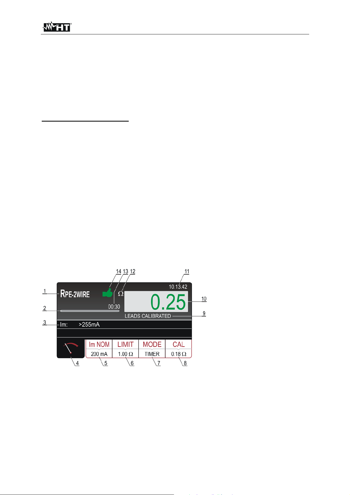
Figure 3: Function selection screen
Select wished function by pressing appropriate touch-screen key, basic measurement screen of
selected function will appear, see an example of RPE-2WIRE basic measurement screen below. Other
functions use adapted screens, but follow the same system.
Figure 4: Basic measurement screen in RPE-2WIRE function
1 ..... Selected function.
2 ..... Progress bar, it follows measurement time during the measurement (in TIMER mode only).
3 ..... Two lines reserved for sub-results (no value in basic screen yet).
4 ..... Measurement screen touch-screen key.
5 ..... Measurement parameters touch-screen keys.
6 ..... Test lead calibration status (LEADS CALIBATED or LEADS NOT CALIBRATED).
7 ..... Measurement result field (result in green colour - OK, result in red colour - not OK, result in white
colour – not judged).
8 ..... Real time clock (hh.mm.ss).
9 ..... Unit of the measurement result.
10 ... Set measurement time (in TIMER mode only).
EN - 12
Page 14
FULLTEST 3
5. MEASUREMENTS
5.1. CONTINUITY - TWO WIRE METHOD (RPE-2WIRE)
Complying with EN 60204-1, continuity of protective bonding circuit between PE terminal and
relevant points of the protective conductor system must be checked by injecting a measurement
current of 0.2 A up to 10 A approx.
5.1.1. RPE-2WIRE DISPLAY EXPLANATION
Adjustable/selectable parameters:
Im NOM - nominal measurement current 200 mA or 25 A AC
LIMIT (meas. current 200 mA) - continuity limit value 0.01 19.99, 20.0 200.0
LIMIT (meas. current 25 A) - continuity limit mode STANDARD, 60204 SET Z or 60204 SET L
LIMIT (test current 25 A, STANDARD mode) -
continuity limit value 0.01 20.00
MODE - measurement mode MANUAL or TIMER
CAL (meas. current 200 mA) - calibration of test leads 0.00 5.00
CAL (meas. current 25 A) - calibration of test leads 0.000 1.999, 2.00 5.00
TIMER - measurement time 00:01 60:00 (1 s 60 min), resolution 1 s
LENGTH - wire length 0.1 999.9 m, resolution 0.1 m
SECTION - wire section 1, 1.5, 2.5, 4, 6, 10, 16, 25, 35, 50 or 70 mm2
MATERIAL - wire material Cu (Cupper) or Al (Aluminium)
ZLINE - input line impedance 0.001 2.000 , resolution 0.001
PROTECTION - over-current protection device MCB B, MCB C, MCB D, MCB K, FUSE gG or
FUSE aM
In - nominal current of protection device Depends on selected protection device, see the
chapter 5.1.3. LIMIT VALUE ADJUSTMENT
Figure 5: Display with RPE-2WIRE test result
1 ..... Selected function.
2 ..... Progress bar, it follows measurement time during the measurement (in TIMER mode only).
3 ..... Sub-result - measurement current Im that was flowing through UUT during the measurement.
4 ..... Measurement screen touch-screen key.
5 ..... Im NOM touch-screen key to select nominal test current (200 mA or 25 A). Currently selected value
is displayed on the bottom of the key.
EN - 13
Page 15
FULLTEST 3
6 ..... LIMIT touch-screen key to select limit value (200 mA measurement) or limit mode (25 A
measurement). Currently selected value or CALC is displayed on the bottom of the key. CALC
message means the value is calculated.
7 ..... MODE touch-screen key to select operation mode (MANUAL or TIMER). Currently selected mode
is displayed on the bottom of the key. TIMER mode is available in 200 mA measurement and in 25
A measurement if STANDARD limit mode is selected.
8 ..... CAL touch-screen key to carry out calibration of test leads. Currently calibrated value is displayed
on the bottom of the key. In case of no calibration, the value 0.00 is displayed in red colour.
9 ..... Test lead calibration status (LEADS CALIBATED or LEADS NOT CALIBRATED).
10 ... Measurement value (in green colour - result OK, in red colour - result not OK).
11 ... Real time clock (hh.mm.ss).
12 ... Unit of measurement result ().
13 ... Set measurement time (in TIMER mode only).
14 ... Measurement result status (symbol in green colour - result OK, symbol in red colour - result
not OK or symbol in yellow colour – result OK, but measurement current too low).
5.1.2. CALIBRATION OF TEST LEADS
In order test leads not to influence the test results, resistance of the leads must be calibrated (zeroed).
Follow the next steps to calibrate test lead’s resistance:
1) Select test current that will be used for later measurement (200 mA or 25 A) by pressing the
Im NOM touch-screen key (5) first.
2) Press the CAL touch-screen key (8), the message “SHORTCIRCUIT TEST LEADS AND PRESS
START TO CALIBRATE” will appear.
3) Connect test leads according to the figure below, make sure two crocodiles are connected as close
as possible to each other to a piece of unisolated wire.
Short unisolated wire
2
Red test leads 2,5 mm
Figure 6: Connection of test leads for calibration purpose
4) Press the START button. The measurement will be done and value without calibration will be
displayed for a moment, then the value will be set to zero (0.00). Test leads are thus calibrated,
measurements can follow.
CAUTION
The calibration must be done separately for each test current (200 mA and 25
A)!
The calibration must be repeated when test leads are changed (replaced,
shortened or extended)!
Max resistance that can be calibrated is 5 !
Existing calibration can be annulled if test leads are opened when calibration
is carried out!
Calibration is not needed in R
PE-4WIRE function!
EN - 14
Page 16

FULLTEST 3
The following specific information may be shown on the display during calibration:
Information displayed Description
SHORTCIRCUIT TEST LEADS
AND PRESS START KEY TO
CALIBRATE
OPEN TEST LEADS,
CALIBRATION ANNULED
Calibration has been started (CAL touch-screen key has
been pressed).
Shortcircuit test leads and press the START button!
Test leads are opened after pressing the START button.
Press YES key … existing calibration will be annulled!
Press NO key … existing calibration will stay untouched!
Connected resistance is higher than 5 and lower than
RPE > 5
CALIBRATION FAILED
measurement range, calibration can not be carried out.
Existing calibration will stay untouched.
Reduce external resistance and repeat the calibration!
5.1.3. LIMIT VALUE ADJUSTMENT
Test current 200 mA is selected:
Limit value can be selected within the range from 0.01 up to 99.99 in steps of 0.01 .
Test current 25 A is selected:
There are three possibilities to select the limit value.
- STANDARD selection.
Limit value can be selected within the range from 0.01 up to 20.00 in steps of 0.01 .
- EN60204 SET L selection.
Limit value is calculated on bases of wire length (L), wire section (SECTION) and wire material
(MATERIAL), where the parameters can be selected/adjusted within the following ranges:
- L (length) 0.1 up to 999.9 m in steps of 0.1 m
- SECTION (wire section) 1, 2.5, 4, 6, 10, 16, 25, 35, 50 or 70 mm
2
- MATERIAL (wire material) Cu (Copper) or Al (Aluminium)
- EN60204 SET Z selection.
Limit value is calculated on bases of entered line impedance (Z
LINE), type of protection (TYPE),
nominal current (IN) and wire section (SECTION), where the parameters can be selected within the
following ranges:
- Zline (line impedance) 0.001 up to 2.000 in steps of 0.001
- TYPE (type of protection) MCB B, MCB C, MCB D, MCB K, FUSE gG or FUSE aM
- In (nominal current) - 6, 10, 13, 16, 20, 25, 32, 40, 50 or 63 A (MCB B)
- 0.5, 1, 1.6, 2, 4, 6, 10, 13, 16, 20, 25, 32, 40, 50 or 63 A (MCB C)
- 0.5, 1, 1.6, 2, 4, 6, 10, 13, 16, 20, 25 or 32 A (MCB D, MCB K)
- 2, 4, 6, 8, 10, 12, 16, 20, 25, 32, 40, 50, 63, 80, 100, 125, 160,
200, 250, 315, 400, 500, 630, 800, 1000 or 1250 A (FUSE gG)
- 2, 4, 6, 8, 10, 12, 16, 20, 25, 32, 40, 50, 63, 80, 100, 125, 160,
200, 250, 315, 400, 500 or 630 A (FUSE aM)
- SECTION (wire section) 1, 2.5, 4, 6, 10, 16, 25, 35, 50 or 70 mm
2
EN - 15
Page 17
FULLTEST 3
5.1.4. RPE-2WIRE MEASUREMENT
Measured quantities and display ranges:
Resistance RPE 0 200 (nominal test current 200 mA)
0 20 (nominal test current 25 A)
Measurement current Im 10 255 mA (nominal test current 200 mA)
0.2 30.0 A (nominal test current 25 A)
1) Select the RPE-2WIRE measurement by pressing the FUNC hard key first.
2) Check selected test current (200 mA or 25 A) and modify it if needed by pressing the Im
NOM (5)
touch-screen key first.
3) Check selected limit value and modify it if needed by pressing the LIMIT (6) touch-screen key first.
Four independent preset limit values are available in STANDARD limit mode selection for quicker
operations. Select the one closest to wished value and modify it by using the + and ― touch screen
keys if needed.
4) Check selected mode (MANUAL or TIMER) and modify it if needed by pressing the MODE (7)
touch-screen key first. In MANUAL mode the measurement will start after pressing the
START/STOP button and will stop after pressing the START/STOP button again. In TIMER mode
the measurement will start after pressing the START/STOP button and will stop after elapsing set
measurement time or after pressing the START/STOP button again.
5) Check the status of test lead calibration and carry out the calibration if needed, see the instructions
in chapter “CALIBRATION OF TEST LEADS” above.
6) Select measurement screen by pressing the
(4) touch-screen key and check all settings again.
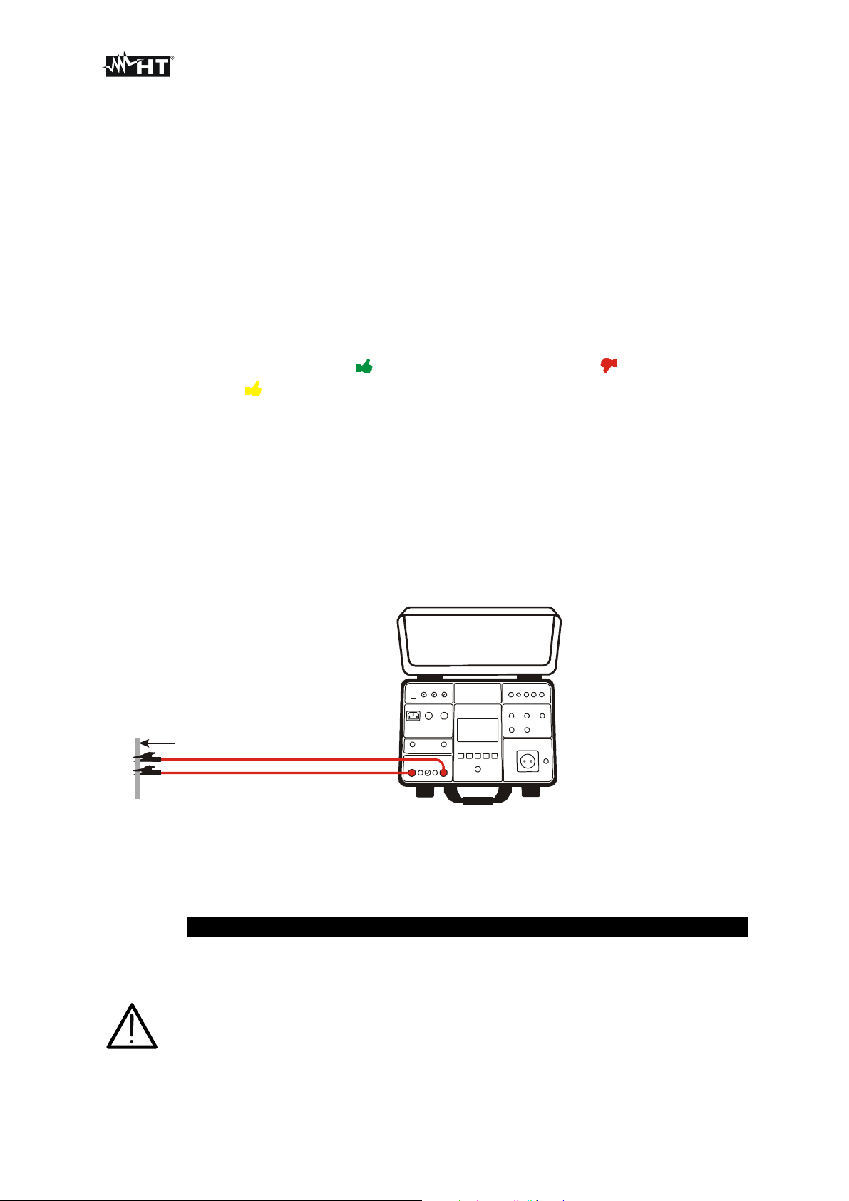
7) Connect the test leads according to the figure below.
CAUTION
Before connecting test leads to UUT obligatory assure there is no external voltage
higher than 10 V between the test points where test leads will be connected to,
otherwise fuse F4 may blow!
Figure 7: Connection of test leads in RPE-2WIRE function
8) Carry out the measurement by pressing the START/STOP button. Test result will currently be
displayed in green (result lower than or equal to set limit value) or in red colour (result higher than
set limit value). Final result will be equipped with green
(result OK) or with red
symbol and with longer beep sound (result not OK) or with yellow
symbol and with beep-beep sound
symbol and with beep-beep sound (result OK, but measurement current was too low). See the
display outlook with test result on figure 5.
9) Save the test result by pressing the SAVE hard key twice, for further instructions see the
“MEMORIZING EXAMPLE” section.
EN - 16
Page 18
FULLTEST 3
CAUTION
Max external voltage between two RPE or between two SENSE test terminals
is 10 VAC, no DC external voltage is allowed! In case of higher external
voltage fuse F4 (T20A/500V, 6.3×32 mm) may blow!
Measurement time in MANUAL mode is limited to 60 min!
The following specific information can be shown on the display during measurement:
Information displayed Description
Measurement result is negative probably because of
shorter test leads than calibrated (negative value is higher
CHECK CALIBRATION
than 5 digits).
Calibrate test leads again!
External voltage higher than 3 V is applied between two
RPE or between two SENSE test terminals
(measurement is not running) or higher than 10 V
EXTERNAL VOLTAGE
(measurement is running).
External voltage higher than 5 30 V is applied between
any RPE or SENSE test terminal and GND.
Remove external voltage!
LIMIT OUT OF RANGE
FUSE F4!
Calculated limit value is < 1 (EN60204 SET Z limit mode)
Fuse F4 is blown.
Internal fuse may be blown!
ERROR 1!
The fuse is not customer replaceable, send the tester into
a service department.
EN - 17
Page 19
FULLTEST 3
5.2. CONTINUITY - FOUR WIRE METHOD (RPE-4WIRE)
Complying with EN 60204-1, continuity of protective bonding circuit between PE terminal and
relevant points of the protective conductor system must be checked by injecting a measurement
current of 0.2 A up to 10 A approx.
Limit values are the values which correspond to the length, cross section and material of measured
conductor.
5.2.1. RPE-4WIRE DISPLAY EXPLANATION
Adjustable/selectable parameters:
LIMIT - continuity limit mode STANDARD, 60204 SET Z or 60204 SET L
MODE - measurement mode MANUAL or TIMER
TIMER – measurement time 00:01 60:00, resolution 1 s
LENGTH - wire length 0.1 999.9 m, resolution 0.1 m
SECTION - wire section 1, 1.5, 2.5, 4, 6, 10, 16, 25, 35, 50 or 70 mm2
WIRE - wire material Cu (Cupper) or Al (Aluminium)
ZLINE - input line impedance 0.001 2.000 , resolution 0.001
PROTECTION - over-current protection device MCB B, MCB C, MCB D, MCB K, FUSE gG or
FUSE aM
In - nominal current of protection device Depends on selected protection device, see the
chapter 5.1.3. LIMIT VALUE ADJUSTMENT
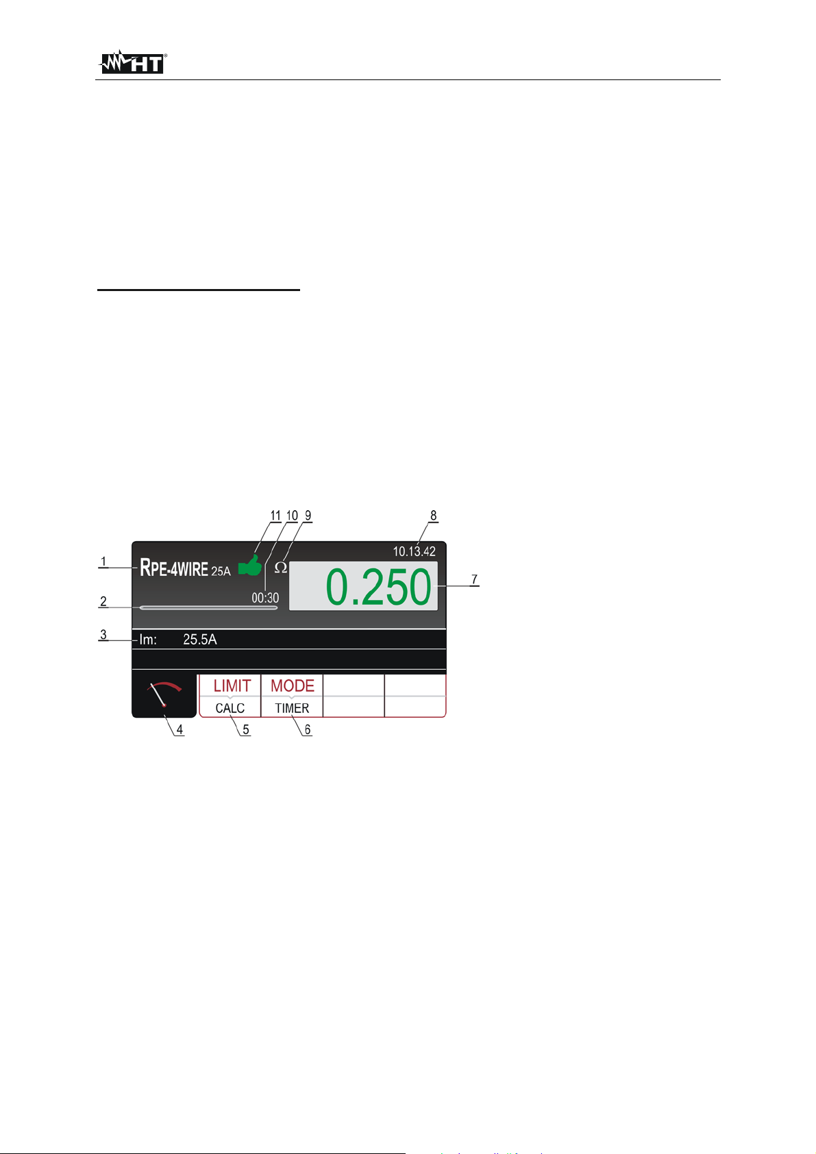
Figure 8: Display with RPE-4WIRE test result
1 ..... Selected function.
2 ..... Progress bar, it follows measurement time during the measurement (in TIMER mode only).
3 ..... Measurement current flowing through UUT during the measurement.
4 ..... Measurement screen touch-screen key.
5 ..... LIMIT touch-screen key to select limit mode (STANDARD, 60204 SET Z or 60204 SET L).
Currently selected value (STANDARD mode) or CALC (60204 SET Z or 60204 SET L mode) is
displayed on the bottom of the key. CALC message means the value is calculated.
6 ..... MODE touch-screen key to select operation mode (MANUAL or TIMER). Currently selected mode
is displayed on the bottom of the key. TIMER mode is available only if STANDARD limit mode is
selected.
7 ..... Measurement value (in green colour - result lower than or equal to set limit value, in red colour -
result is higher than set limit value).
8 ..... Real time clock (hh.mm.ss).
9 ..... Unit of measurement result ().
EN - 18
Page 20

FULLTEST 3
10 ... Set measurement time (in TIMER mode only).
11 ... Measurement result status (symbol in green colour - result OK, symbol in red colour –
result not OK).
5.2.2. CALIBRATION OF TEST LEADS
The calibration is not needed because of 4-wire method.
EN - 19
Page 21
FULLTEST 3
5.2.3. RPE-4WIRE MEASUREMENT
Measured quantities and display ranges:
Continuity RPE 0 20
Test current 0.2 30 A
1) Select the RPE-4WIRE function by pressing the FUNC hard key first.
2) Check selected limit value and modify it if needed by pressing the LIMIT (6) touch-screen key first.
Four independent preset limit values are available in STANDARD limit mode selection for quicker
operations. Select the one closest to wished value and modify it by using the + and ― touch screen
keys if needed.
3) Check selected mode and modify it if needed by pressing the MODE (7) touch-screen key first.
4) Select measurement screen by pressing the (4) touch-screen key and check all settings again.
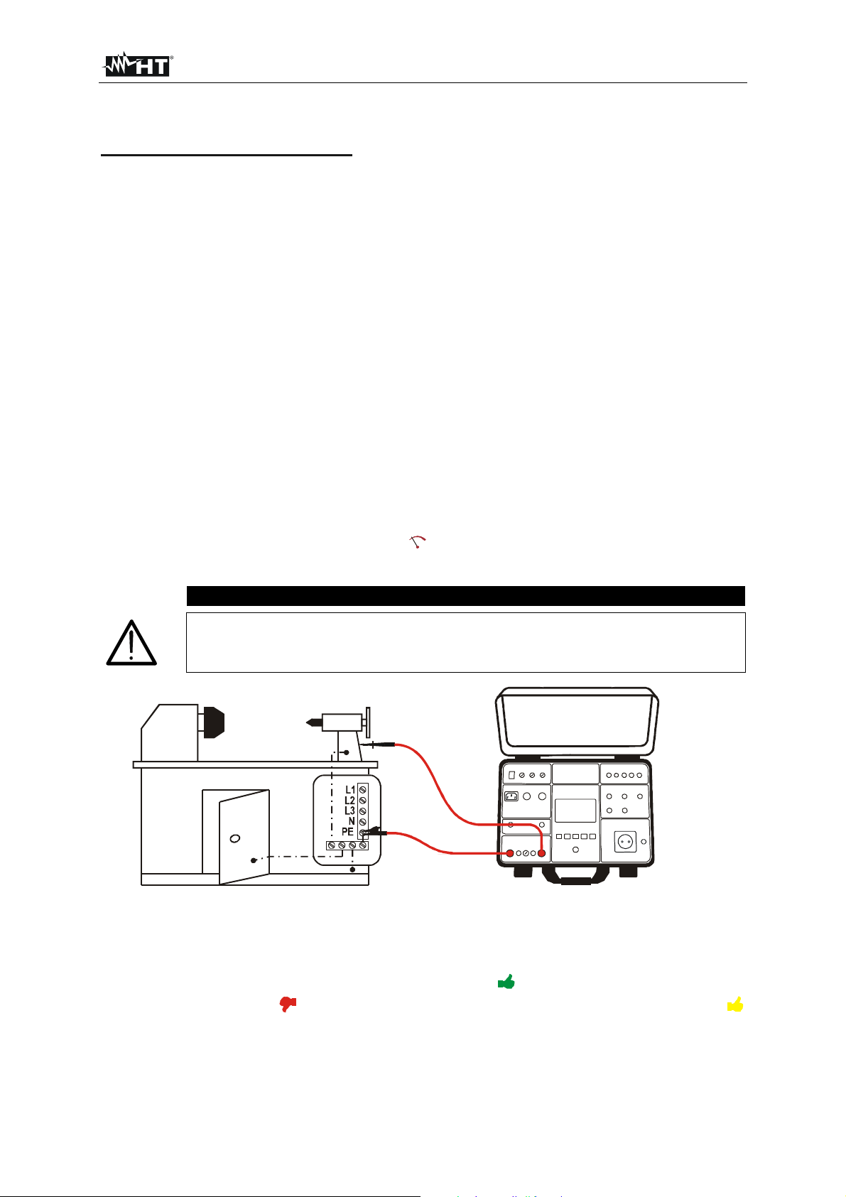
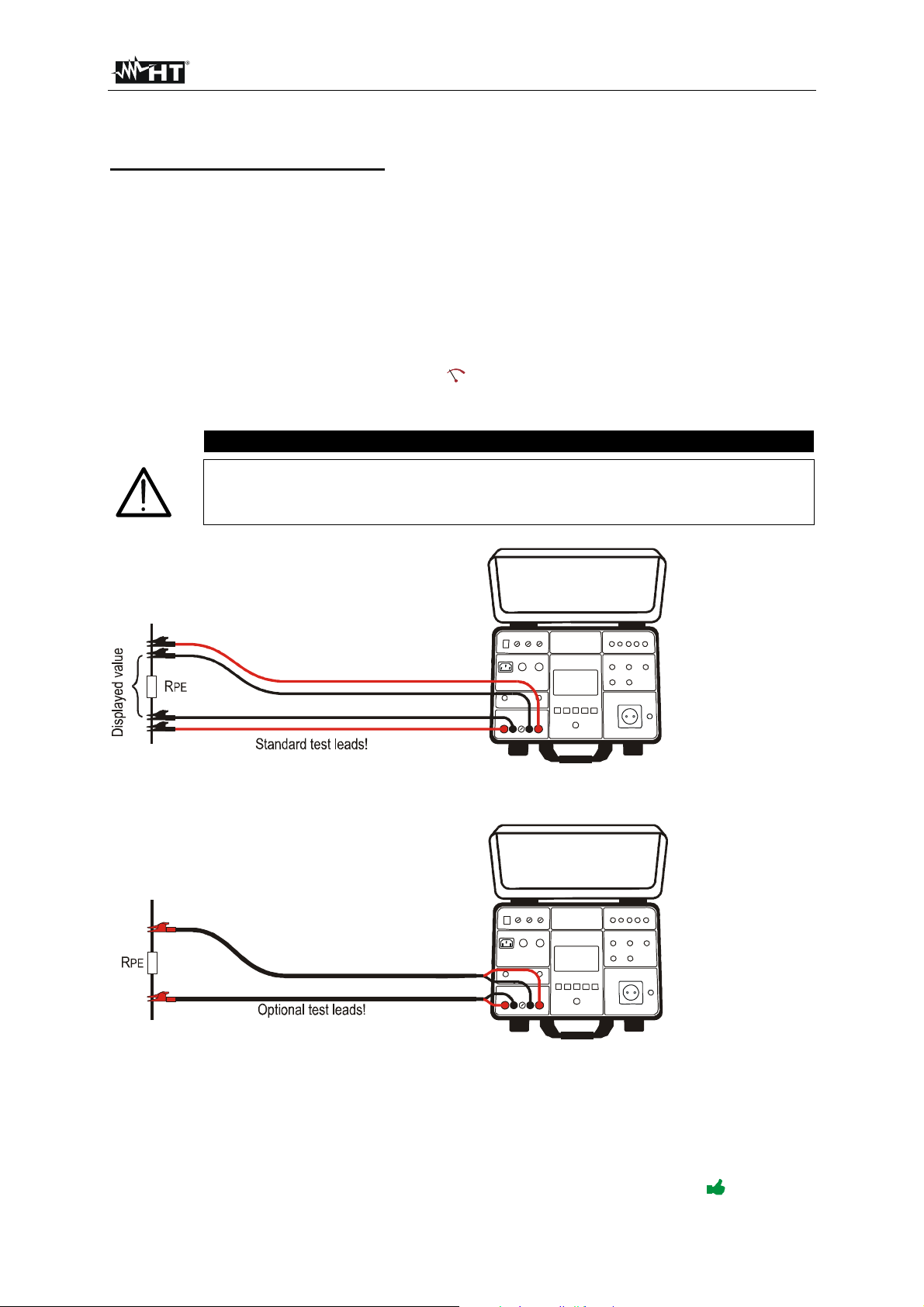
5) Connect the test leads according to the figure below.
CAUTION
Before connecting test leads to UUT obligatory assure there is no external voltage
higher than 10 V between the test points where test leads will be connected to,
otherwise fuse F4 may blow!
Figure 9: Connection of standard test leads
Figure 10: Connection of optional Kelvin test leads
6) Carry out the measurement by pressing the START/STOP button. The measurement will start to
run and will be stopped after pressing the START/STOP button again (MANUAL mode) or after
elapsing set measurement time (TIMER mode).
Test result will currently be displayed in green (result lower than or equal to set limit value) or in red
colour (result is higher than set limit value). Final result will be equipped with green symbol and
EN - 20
Page 22
FULLTEST 3
with beep-beep sound (result OK) or with red symbol and with longer beep sound (result not
OK). See the display outlook with test result on Figure 8.
7) Save the test result by pressing the SAVE hard key twice, for further instructions see the
“MEMORIZING EXAMPLE” section.
CAUTION
Max external voltage between two RPE or between two SENSE test terminals
is 10 VAC, no DC external voltage is allowed! In case of higher external
voltage fuse F4 (T20A/500V, 6.3×32 mm) may blow!
If SENSE test leads are not connected, then measurement result will include
also the resistance of current test leads.
Measurement time in MANUAL mode is limited to 60 min!
The following specific information can be shown on the display during measurement:
Information displayed Description
External voltage higher than 3 VAC is applied between
two RPE or between two SENSE test terminals
(measurement is not running) or higher than 10 VAC
EXTERNAL VOLTAGE
(measurement is running).
External voltage higher than 5 30 V is applied between
any RPE or SENSE test terminal and GND.
Remove external voltage!
FUSE F4!
Fuse F4 is blown.
Internal fuse may be blown!
EROR1!
The fuse is not customer replaceable, send the tester into
a service department.
EN - 21
Page 23
FULLTEST 3
5.3. INSULATION RESISTANCE (M)
• According to EN 60204-1, the insulation resistance between shorted active conductors of power
circuit and the earth bonding system must be checked by applying a test voltage of 500 V DC. The
limit value is 1 M.
• Ensure that all switches on the unit under test are closed in order to test all it’s components. For
purpose of the measurement, all active conductors (L1, L2, L3 and N) must be shortcircuited.
5.3.1. RISO DISPLAY EXPLANATION
Adjustable/selectable parameters:
Utest - nominal test voltage 100, 250, 500 or 1000 V DC
MODE - operation mode MANUAL, TIMER or AUTO
LIMIT - insulation resistance limit 0.01 100.0 M
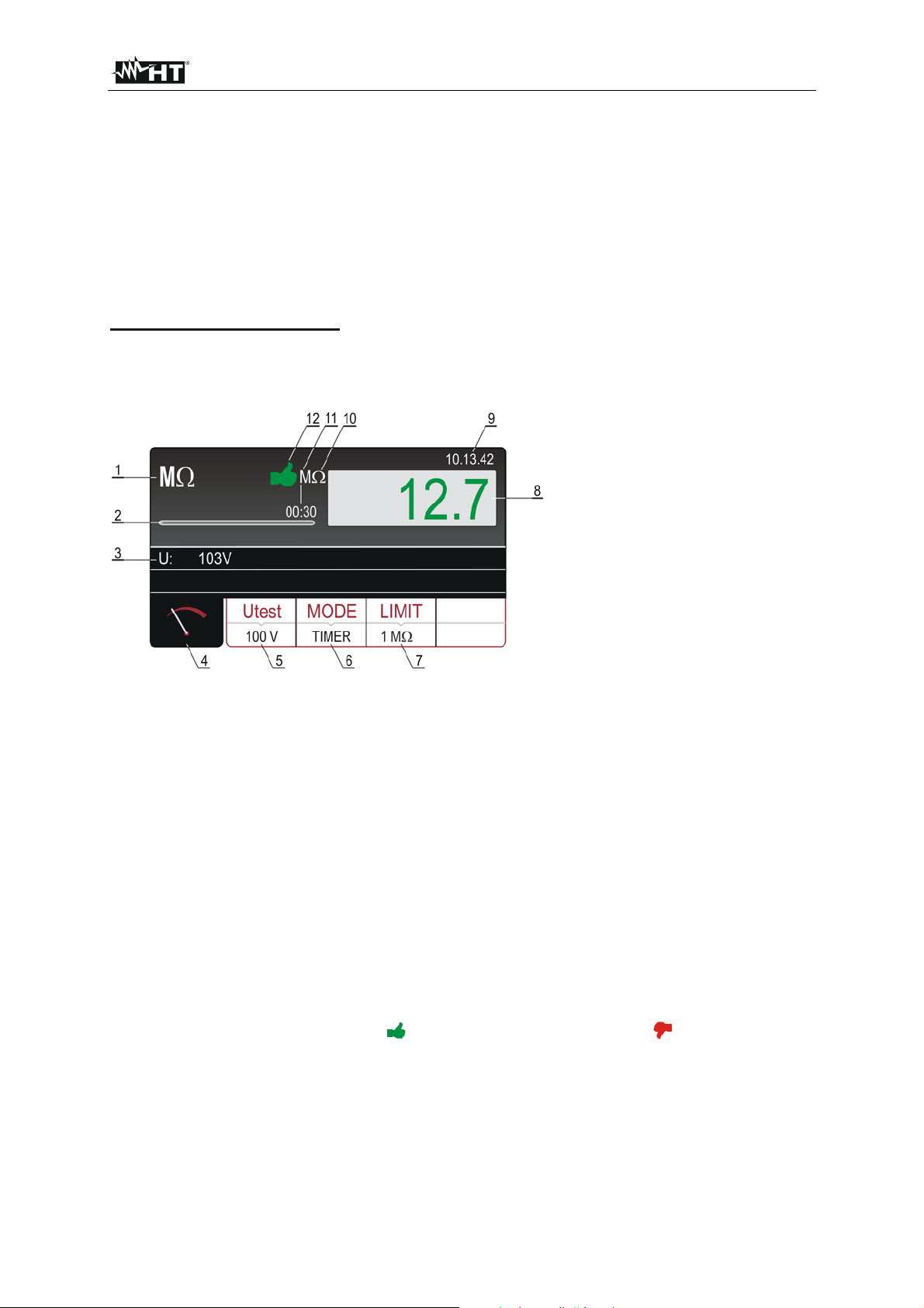
Figure 11: Display with RISO test result
1 ..... Selected function.
2 ..... Progress bar, it follows measurement time during the measurement (in TIMER mode only).
3 ..... Test voltage applied during the measurement.
4 ..... Measurement screen touch-screen key.
5 ..... Utest touch-screen key to select nominal test voltage (100, 250, 500 or 1000 V). Currently selected
value is displayed on the bottom of the key.
6 ..... MODE touch-screen key to select operation mode (MANUAL, TIMER or AUTO). Currently selected
mode is displayed on the bottom of the key.
7 ..... LIMIT touch-screen key to select limit insulation resistance. Currently selected value is displayed
on the bottom of the key.
8 ..... Measurement value (in green colour - result OK, in red colour - result not OK).
9 ..... Real time clock (hh.mm.ss).
10 ... Unit of the measurement result M).
11 ... Set measurement time (in TIMER mode only).
12 ... Measurement result status (symbol in green colour - result OK, symbol in red colour - result
not OK).
EN - 22
Page 24

FULLTEST 3
5.3.2. RISO MEASUREMENT
Measured quantities and display ranges:
Insulation resistance RINS 0 100 M (test voltage 100 V)
0 250 M (test voltage 250 V)
0 500 M (test voltage 500 V)
0 1000 M (test voltage 1000 V)
Test voltage Utest 0 1100 V
1) Select M function by pressing the FUNC hard key first.
2) Check selected test voltage (100, 250, 500 or 1000V) and modify it if needed by pressing the Utest
(5) touch-screen key first.
3) Check selected mode and modify it if needed by pressing the MODE (6) touch-screen key first.
MANUAL, TIMER or AUTO mode can be selected.
4) Check selected limit value and modify it if needed by pressing the LIMIT (7) touch-screen key first.
Four independent preset limit values are available for quicker operations. Select the one closest to
wished value and modify it by using the + and ― touch screen keys if needed.
5) Select measurement screen by pressing the (4) touch-screen key and check all settings again.
6) Connect the test leads according to the figure below.
Figure 12: Connection of test leads
7) Carry out the measurement by pressing the START/STOP button. The measurement will start to
run and will be stopped after pressing the START/STOP button again (MANUAL mode) or after
elapsing set measurement time (TIMER mode) or after reaching stabile result (AUTO mode).
Test result will currently be displayed in green colour (result higher than or equal to set limit value)
or in red colour (result lower than set limit value). Final result will be equipped with green
symbol and with beep-beep sound (result OK) or with red
symbol and with longer beep sound
(result not OK). See the display outlook with test result on Figure 11.
8) Save the test result by pressing the SAVE hard key twice, for further instructions see the
“MEMORIZING EXAMPLE” section.
EN - 23
Page 25
FULLTEST 3
CAUTION
Connect COM test lead to chassis if the UUT is grounded. In case of reversed
test leads measurement result may be affected by instrument’s internal
resistance of 10 M!
Due to the measurement of insulation resistance, capacitive UUT will be
charged with test voltage. The UUT will be discharged after finishing the
measurement via internal resistance of approx. 2 M. The UUT can retain
dangerous voltage in case of premature removal of test leads. Ensure that the
UUT is discharged through the measurement instrument (not through short
circuit)!
Measurement time in MANUAL mode is limited to 60 min!
The following specific information can be shown on the display during the measurement:
Information displayed Description
External voltage higher than 10 VAC approx. is applied
between positive and negative test terminals
(measurement is not running) or higher than 50 VAC
approx. (measurement is running).
EXTERNAL VOLTAGE
Negative external voltage higher than 10 VDC approx. is
applied between positive and negative test terminals
(measurement is running).
Remove external voltage!
External capacitor (or internal) that was charged during the
DISCHARGING!
measurement is discharging.
Wait until the message disappears! Do not disconnect test
leads until the message is present!
EN - 24
Page 26

FULLTEST 3
5.4. DIELECTRIC (DIELECTRIC)
According to EN 60204-1, electric equipment must withstand a voltage test between shorcircuited
active conductors of power circuit and the earth bonding system for approx. 1 s.
The test shall be carried out at twice the rated supply (or 1000 V whichever is greater) 50 Hz.
Components not rated for this test voltage may be disconnected before carrying out the test.
5.4.1. WARNINGS
WARNING, DANGER OF ELECTRICAL SHOCK
The Machine Tester FULLTEST 3 supplies high voltage of a dangerous power. According to EN 50191
the following precautionary measures must be taken prior to a test:
• Block access to danger area.
• Put up warning signs (Attention! High voltage, danger to life).
• Install warning lamps (red, green) to be easily visible.
• Install EMERGENCY-OFF switch into the mains installation outside the dangerous area.
• Electrical trained personnel may only do the tests under supervision of specialist staff and have to be
trained regularly.
• Use safety probes with protection against contact or with two-hand operation only. Always hold only
one probe in one hand.
• Connecting one test terminal to the UUT and working with one probe or holding both probes in one
hand is prohibited.
• It is prohibited to touch the unit under test during the test. If need be, additional measures must be
taken (e.g. cover made of insulating mats) to protect the person performing the test against
inadvertent contact with the test object.
Testing may commence only after all safety measures were taken.
Ensure that all switches on the UUT are closed in order to test all it’s components. For the purpose of
measurement all active conductors (L1, L2, L3 and N) must be shortcircuited.
EN - 25
Page 27
FULLTEST 3
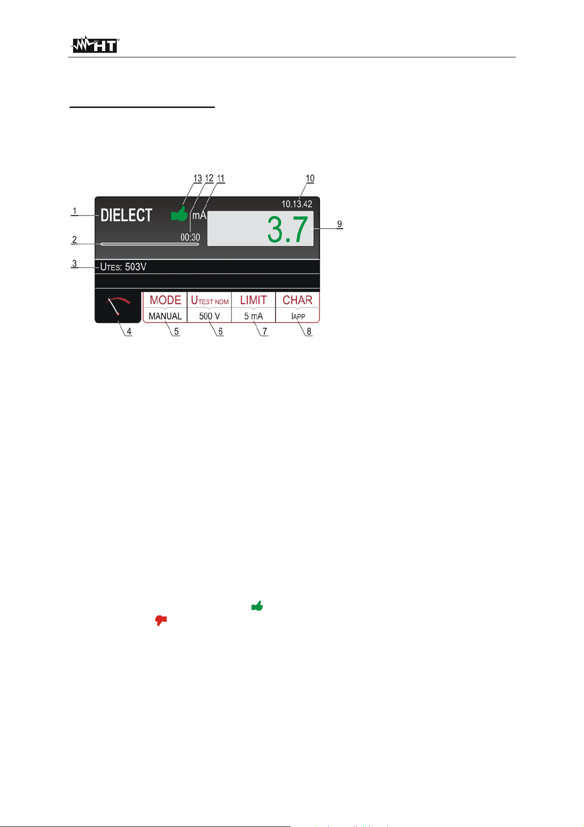
5.4.2. DIELECTRIC DISPLAY EXPLANATION
Adjustable/selectable parameters:
MODE - operation mode MANUAL, RAMP or BURN
UTEST NOM - nominal test voltage 250 5100 V AC
LIMIT - current limit 1 110 mA
CHAR - current character IAPP or IREAL
Figure 13: Display with DIELECTRIC test result
1 ..... Selected function.
2 ..... Progress bar, it follows test time during the measurement (in RAMP mode only).
3 ..... Test voltage applied during the measurement.
4 ..... Measurement screen touch-screen key.
5 ..... MODE touch-screen key to select operation mode (MANUAL, RAMP or BURN). Currently selected
mode is displayed on the bottom of the key.
6 ..... UTEST NOM touch-screen key to select nominal test voltage (250 up to 5100 V). Currently
selected value is displayed on the bottom of the key.
7 ..... LIMIT touch-screen key. Currently selected limit leakage current (trip out current) is displayed on
the bottom of the key.
8 ..... CHAR (character) touch-screen key to select the character of displayed leakage current (IAPP or
REAL). Currently selected character is displayed on the bottom of the key.
I
9 ..... Leakage current in green colour if the result is lower than or equal to set limit value. If break-
through occurred during the test then limit value will be displayed in red colour.
10 ... Real time clock (hh.mm.ss).
11 ... Unit of the test result (mA).
12 ... Set measurement time (in RAMP mode only).
13 ... Measurement result status (symbol
in green colour - result lower than or equal to set limit
value, symbol in red colour - break through occurred during the test or result higher than set
limit value).
EN - 26
Page 28
FULLTEST 3
5.4.3. DIELECTRIC TEST
Measured quantities and display ranges:
Apparent leakage current IAPP 0 200 mA
Real leakage current IREAL 0 200 mA
Test voltage 250 5.100 V
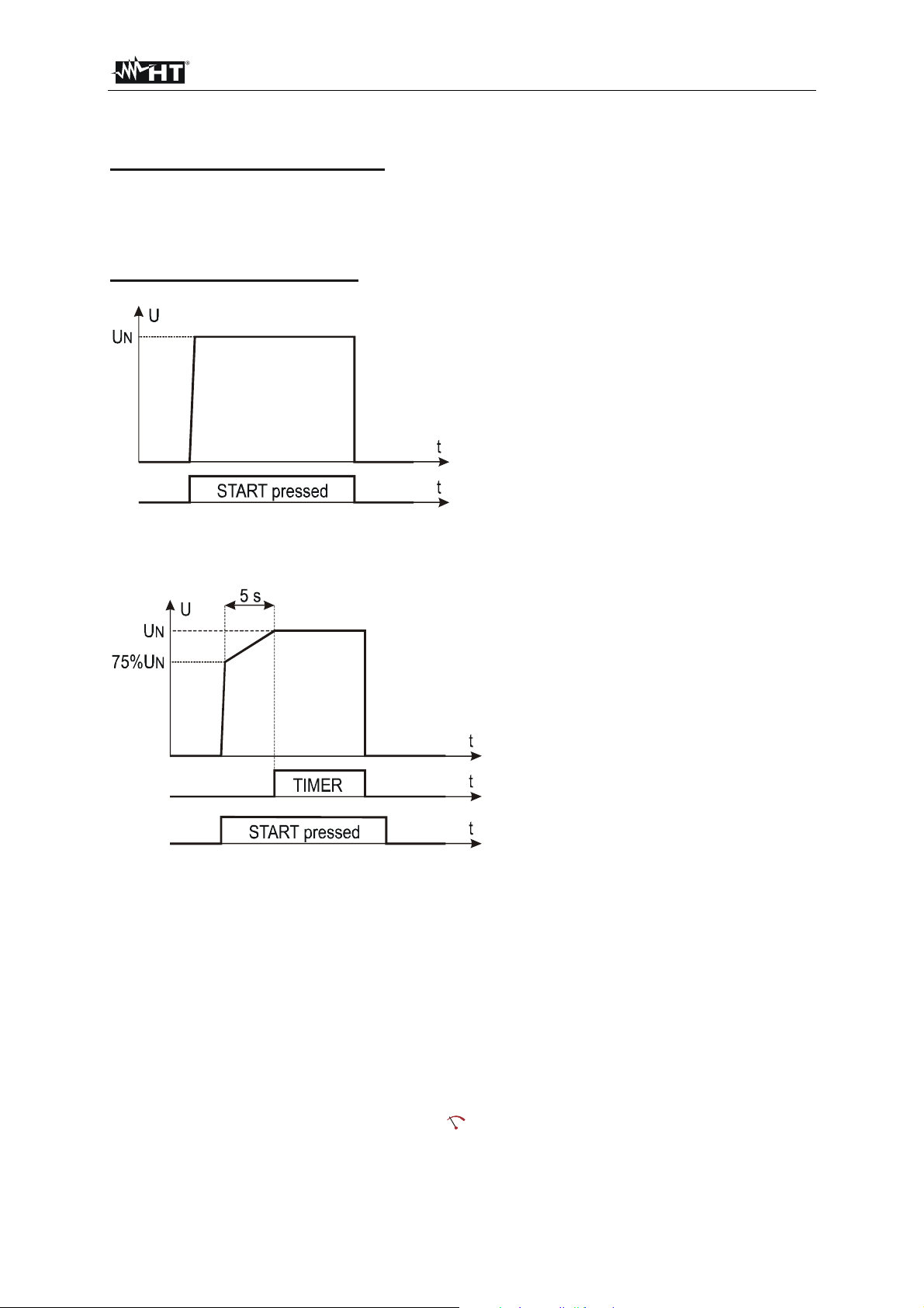
Explanation of measurement modes:
MANUAL or BURN mode:
Figure 14: Presence of test voltage with regard to pressed START button in MANUAL or BURN mode
RAMP mode:
Figure 15: Presence of test voltage with regard to pressed START button and set time in RAMP mode
1) Select DIELECTRIC measurement by pressing the FUNC hard key first.
2) Check selected mode and correct it if needed by pressing the MODE (5) touch-screen key first.
MANUAL, RAMP or BURN mode can be selected.
3) Check selected test voltage (250 up to 5100V) and correct it if needed by pressing the UTES NOM
(6) touch-screen key first.
4) Check selected limit current and correct it if needed by pressing the LIMIT (7) touch-screen key
first. Four independent preset limit currents are available for quicker operations. Select the one
closest to wished value and modify it by using the + and ― touch screen keys if needed.
5) Check selected character of displayed current (IAPP or IREAL) and correct it if needed by pressing
the CHAR (8) touch-screen key first.
6) Select measurement screen by pressing the (4) touch-screen key and check all settings again.
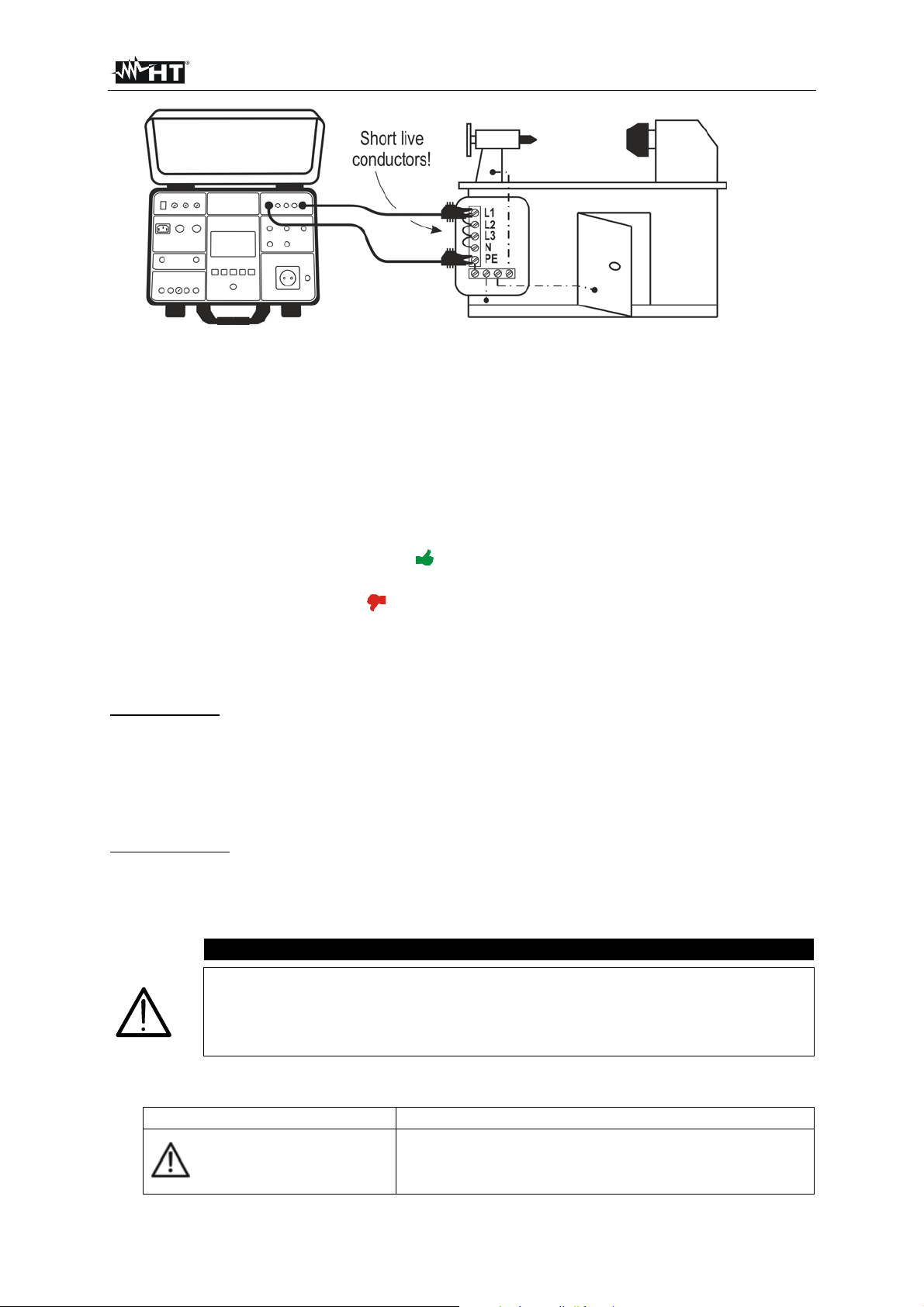
7) Connect the test leads according to the figure below.
EN - 27
Page 29
FULLTEST 3
Figure 16: Connection of test leads
8) Carry out the test by pressing the START/STOP button. Warning with explanation of how to
connect test leads with regard to selected test voltage will be displayed. Check the connection then
confirm it by pressing the YES touch-screen key, the message “READY” will appear and will stay
present for 10 seconds. START/STOP button is active while “READY” message is present. Press
and keep pressing the START/STOP button, test voltage will be applied to test terminals. The test
will be stopped after releasing the START/STOP button (MANUAL or BURN mode) or after
elapsing set test time (RAMP mode).
Test result will currently be displayed in green colour if it is lower than or equal to set limit value.
Final result will be equipped with green symbol and with beep-beep sound (result OK). If break
through occurred during the test then the test will be stopped and limit test current will be displayed
in red colour equipped with red symbol and with longer beep sound. See the display outlook
with test result on the figure 13.
9) Save test result by pressing the SAVE hard button twice, for further instructions see the
“MEMORIZING EXAMPLE” section.
SAFETY INPUT
In order to reach higher level of safety the SAFETY INPUT connector is installed. Safety switch of a
mechanical barrier can be connected there in order to disable DIELECTRIC function in case the safety
switch is opened. For this purpose select SAFETY INPUT enabled mode in the menu as follows:
MENU hard key SETUP touch-screen key SAFETY touch-screen key ENABLED touch-
screen key.
WARNING LAMP
According to EN 50191 the highest level of safety must be undertaken when working with high voltages
like used in DIELECTRIC test. For this purpose the FULLTEST 3 offers an output to drive the high
voltage warning lamp. Use only the lamps supplied by original supplier of the FULLTEST 3 tester.
CAUTION
Always connect COM terminal to GND if measured UUT is grounded,
otherwise possible capacitive leakage current may flow to ground which may
disturb the measurement!
Measurement time in MANUAL mode is limited to 60 min!
The following specific information can be shown on the display during measurement:
Information displayed Description
Internal fuse may be blown!
EROR1!
The fuse is not customer replaceable, send the tester into
a service department.
EN - 28
Page 30

FULLTEST 3
5.5. RCD (RCD)
5.5.1. RCD DISPLAY EXPLANATION
Adjustable/selectable parameters:
TYPE - type of RCD AC, A or B
CHARACTERISTIC - RCD characteristic GENERAL, SELECTIVE or DELAYED
IN - nominal differential current 10, 30, 100, 300, 500, 650 or 1000 mA
MEAS - type of measurement t/1/2IN, t/IN, t/2IN, t/5IN, I or AUTO
POL - test current polarity POS (positive) or NEG (negative)
DELAY – delay time in DELAY characteristic 0 700 ms
Figure 17: Display with RCD test result
1 ..... Selected function.
2 ..... Selected limit contact voltage (25 or 50 V). It can be selected in MENUSETUPCONTACT
VOL. menu.
3 ..... Sub-results - mains voltages UL/N and UL/PE at which the test was carried out.
4 ..... Measurement screen touch-screen key.
5 ..... TYPE touch-screen key to select the type of RCD (AC, A or B) and characteristic (GENERAL,
SELECTIVE or DELAYED). Currently selected type and characteristic are displayed on the bottom
of the key.
N touch-screen key to select nominal differential current of the RCD (10, 30, 100, 300, 500, 650
6 ..... I
or 1000 mA). Currently selected value is displayed on the bottom of the key.
7 ..... MEAS touch-screen key to select the measurement (t
/1/2IN, t/IN, t/2IN, t/5IN, I or AUTO).
Currently selected measurement is displayed on the bottom of the key.
8 ..... POL touch-screen key to select test current polarity (POS - positive or NEG - negative).
9 ..... Test result (in green colour - result OK, in red colour - result not OK).
10 ... Real time clock (hh.mm.ss).
11 ... Unit of the test result (ms).
12 ... Measurement result status (symbol in green colour - result OK, symbol in red colour - result
not OK).
EN - 29
Page 31
FULLTEST 3
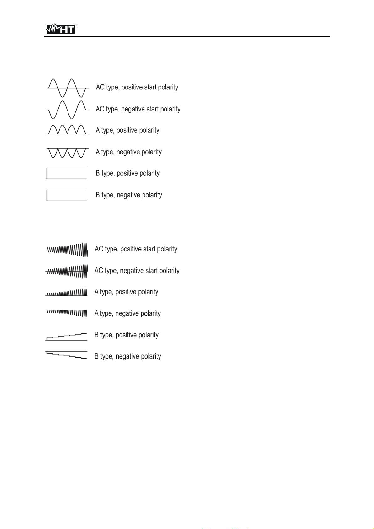
5.5.2. EXPLANATION OF RCD TEST CURRENTS
See the figures below for test current shapes with regard to selected RCD type and test current polarity.
Figure 18: Test current shapes with regard to selected RCD type and test current polarity in trip time
measurement
Figure 19: Test current shapes with regard to selected RCD type and test current polarity in RAMP test
EN - 30
Page 32
FULLTEST 3
5.5.3. RCD MEASUREMENT
Measured quantities and display ranges:
Trip out time at IN/2 0 1000 ms (AC, A, B, general, selective, delayed)
Trip out time at IN 0 1000 ms (AC, A, B, general, selective, delayed)
Trip out time at 2IN 0 200 ms (AC, A, general), 0 250 ms (AC, A, selective)
Trip out time at 4IN 0 200 ms (B, general), 0 250 ms (B, selective)
Trip out time at 5IN 0 50 ms (AC, A, general), 0 150 ms (AC, A, selective)
AUTO test YES (general, selective)
Trip out current (Ramp test) 10 110% of IN in steps of 5% of IN (general)
Input requirements:
Mains voltage UL/N (READY condition) 100 265 V AC
Mains voltage U
L/PE (READY condition) 100 265 V AC
1) Select the RCD function by pressing the FUNC hard key first.
2) Check selected RCD type (AC, A or B) and selected characteristic (GENERAL, SELECTIVE or
DELAYED) and modify it if needed by pressing the TYPE (5) touch-screen key first. If DELAYED
characteristic is selected, the screen will turn to delay time adjustment mode automatically.
3) Select nominal differential current by pressing the IN touch-screen key first.
4) Select wished measurement by pressing the MEAS touch-screen key first (t/1/2IN, t/IN, t/2IN,
t/5IN, I or AUTO).
5) Check selected polarity and modify it if needed by pressing the POL (8) touch-screen key first.
6) Select measurement screen by pressing the (4) touch-screen key and check all settings again.
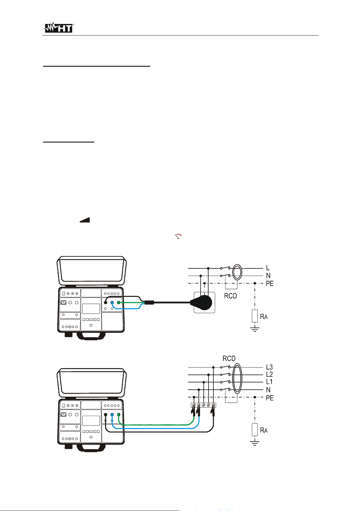
7) Connect the test leads according to one of the figures below.
Figure 20: Connection of schuko test cable
Figure 21: Connection of test leads
EN - 31
Page 33
FULLTEST 3
READY message will appear as soon as the tester is properly connected to the installation and
mains voltage is present, see the “Input conditions” above.
8) Carry out the measurement by pressing the START button.
9) Test result will be displayed in green colour equipped with green symbol and with beep-beep
sound if it is within limit range, see the table of allowed trip out times below. If the result is out of
limit range, then it will be displayed in red colour equipped with red symbol and with longer
beep sound. See the display outlook with test result on the figure 17.
10) Save the test result by pressing the SAVE hard key twice, for further instructions see the
“MEMORIZING EXAMPLE” section.
11) Press the EXIT hard key to clear displayed result, actual input voltages UL/N and UL/PE will start to
be displayed again.
Allowed trip out times:
Characteristic / I IN/2 IN 2IN (4) 5IN
GENERAL >1000 ms
SELECTIVE >1000 ms
DELAYED >1000 ms
300 ms 150 ms 40 ms
130 500 ms 60 200 ms 50 150 ms
D (D + 300) ms
- -
D … Delay time which can be set to 0 700 ms
CAUTION
When selecting RCD type (TYPE), nominal differential current (IN) or
measurement (MEAS) it may happen that wished parameter will not be
available (displayed in watery colour). In this case the level of other parameter
or even other two parameters shall be reduced first.
In case both voltages UL/N and UL/PE within required range 100 265 V are
present at L/N/PE test terminals (also displayed) but there is no READY
message displayed, check if energizing socket is correctly earthed!
The following specific information can be shown on the display during the measurement:
Information displayed Description
L/N or UL/PE out of required range 100
VOLTAGE OUT OF RANGE
Input voltage U
265 V after pressing the START key.
Input voltage failed during the measurement (disconnection
MEASUREMENT FAILED!
FUSE F3!
of test leads, installation fuse tripped etc.)
Fuse F3 is blown.
Internal circuitry is overheated.
HOT!
Wait to cool it down!
EN - 32
Page 34
FULLTEST 3
5.6. LOOP IMPEDANCE / SHORT-CIRCUIT CURRENT (LOOP)
• According to EN 60204-1, the conditions for protection against electric shock in installations with
automatic disconnection of mains voltage are:
• Measurement or evaluation of fault loop impedance and testing the over-current protection device
involved in the fault loop.
• Limit values are shown in the Table 10 of EN 60204-1.
5.6.1. LOOP DISPLAY EXPLANATION
Adjustable/selectable parameters:
MODE - measurement mode LOOPL/N, LOOPL/L, LOOPL/PE, IMP57L/N, IMP57L/L or IMP57L/PE
LIMIT - limit value mode STD, kA, I2t, TRIP CURR. or Ut, see the explanation below
Ib – breaking capacity of protection 1, 1.5, 3, 4.5, 6, 10, 15, 16, 20 or 25 kA
PROTECTION - type of protection MCB B, MCB C, MCB D, MCB K, FUSE gG or FUSE aM
In - nominal current of protection See the values in chapter “LIMIT VALUE EXPLANATION” below
Tset - max allowed tripping time 0.1 s, 0.2 s, 0.4 s or 5 s
WIRE - wire material Cu (Copper) or Al (Aluminium)
COATING - wire coating PVC, BUTYL RUBBER or EPR/XLPE
SECTION - wire section 1, 1.5, 2.5, 4, 6, 10, 16, 25, 35, 50 or 70 mm2
N - number of conductors 1 99
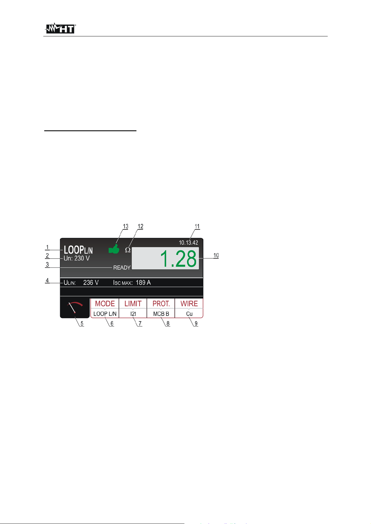
Figure 22: Display with LOOPL/N test result
1 ..... Selected function.
2 ..... Selected nominal voltage (230 or 240 V) needed for calculation of short-circuit current.
3 ..... READY message. It is displayed when present mains voltage UL/L, UL/N or UL/PE within required
range is present.
4 ..... Sub-results - mains voltage U
calculated prospective short-circuit current I
L/PE or UL/PE or UL/L at which the measurement has been done and
SC.
5 ..... Measurement screen touch-screen key.
6 ..... MODE touch-screen key to select measurement mode (LOOP L/N, LOOP L/L, LOOP L/PE, IMP57
L/N, IMP57 L/L or IMP57 L/PE). Currently selected mode is displayed on the bottom of the key.
7 ..... LIMIT touch-screen key to select limit mode (STD, kA, I2t, TRIP CURR. or Ut). Currently selected
mode is displayed on the bottom of the key.
8 ..... PROT. (protection) touch-screen key to select the type of protection (MCB B, MCB C, MCB D,
MCB K, FUSE gG or FUSE aM) and nominal current of selected protection. Currently selected type
is displayed on the bottom of the key.
EN - 33
Page 35

FULLTEST 3
9 ..... WIRE touch-screen key to select the material of measured wire (Cu or Al), coating (PVC, BUTYL
RUBBER or EPR/XLPE), section (1, 1.5, 2.5, 4, 6, 10, 16, 25, 35, 50 or 70 mm
2
) and number of
conductors (1 99). Currently selected material is displayed on the bottom of the key.
10 ... Measurement result (in green colour - result OK, in red colour - result not OK).
11 ... Real time clock (hh.mm.ss).
12 ... Unit of the test result ().
13 ... Measurement result status (symbol in green colour - result OK, symbol in red colour - result
not OK).
5.6.2. LIMIT VALUE EXPLANATION
There are five possibilities to select the limit prospective short-circuit current ISC LIM, which is the bases
for final evaluation.
STD - no verification.
No limit is used in this case meaning test result is not evaluated and is therefore always considered as
neutral (displayed in white colour).
kA - verification if short-circuit current is lover than breaking capacity of involved over-current protection
device.
Measured ISC MAX must be lower or equal than entered breaking capacity Ib of involved over-current
protection device, where breaking capacity Ib can be selected among the following values:
- Ib (breaking capacity) 1, 1.5, 3, 4.5, 6, 10, 15, 16, 20 or 25 kA
I2t - verification if over-current protection device reacts before wires are overheated and thus damaged.
On bases of measured ISC MAX and entered over-current protection device (PROTECTION) and
nominal current of the over-current protection device (In) trip out time of the over-current protection
device (t) is calculated. See the evaluation equation in the table “PROSPECTIVE SHORT-CIRCUIT
CURRENT CALCULATION” below. Entered parameters can be selected among the following values:
- PROT (type of protection) MCB B, MCB C, MCB D, MCB K, FUSE gG or FUSE aM
- In (nominal current) - 6, 10, 13, 16, 20, 25, 32, 40, 50 or 63 A (MCB B)
- 0.5, 1, 1.6, 2, 4, 6, 10, 13, 16, 20, 25, 32, 40, 50 or 63 A (MCB C)
- 0.5, 1, 1.6, 2, 4, 6, 10, 13, 16, 20, 25 or 32 A (MCB D, MCB K)
- 2, 4, 6, 8, 10, 12, 16, 20, 25, 32, 40, 50, 63, 80, 100, 125, 160,
200, 250, 315, 400, 500, 630, 800, 1000 or 1250 A (FUSE gG)
- 2, 4, 6, 8, 10, 12, 16, 20, 25, 32, 40, 50, 63, 80, 100, 125, 160,
200, 250, 315, 400, 500 or 630 A (FUSE aM)
- MATERIAL (wire material) Cu (Cupper) or Al (Aluminium)
- COATING (wire coating) PVC, BUTYL RUBBER or EPR/XLPE
- SECTION (wire section) 1, 1.5, 2.5, 4, 6, 10, 16, 25, 35, 50, 70 mm
2
- N (number of conductors) 1 99
TRIP CURRENT - verification if over-current protection device reacts within set time at measured shortcircuit current.
On bases of measured ISC MIN and entered over-current protection device (PROTECTION) and nominal
current of the over-current protection device (In) trip out time is calculated which must be lower than or
equal to entered Tset. Entered parameters can be selected among the following values:
- PROT (type of protection) MCB B, MCB C, MCB D, MCB K, FUSE gG or FUSE aM
- In (nominal current) - 6, 10, 13, 16, 20, 25, 32, 40, 50 or 63 A (MCB B)
- 0.5, 1, 1.6, 2, 4, 6, 10, 13, 16, 20, 25, 32, 40, 50 or 63 A (MCB C)
- 0.5, 1, 1.6, 2, 4, 6, 10, 13, 16, 20, 25 or 32 A (MCB D, MCB K)
EN - 34
Page 36
FULLTEST 3
- 2, 4, 6, 8, 10, 12, 16, 20, 25, 32, 40, 50, 63, 80, 100, 125, 160,
200, 250, 315, 400, 500, 630, 800, 1000 or 1250 A (FUSE gG)
- 2, 4, 6, 8, 10, 12, 16, 20, 25, 32, 40, 50, 63, 80, 100, 125, 160,
200, 250, 315, 400, 500 or 630 A (FUSE aM)
- Tset (max trip time) 0.1, 0.2, 0.4 or 5 s
Ut - verification if short-circuit current is high enough over-current protection device to react within set
time.
On bases of entered over-current protection device (PROTECTION), nominal current of the over-current
protection device (In) and Tset required short-circuit current (Ia) is calculated. Measured ISC MIN must
be higher than or equal to calculated current Ia. Entered parameters can be selected among the
following values:
- PROT (type of protection) MCB B, MCB C, MCB D, MCB K, FUSE gG or FUSE aM
- In (nominal current) - 6, 10, 13, 16, 20, 25, 32, 40, 50 or 63 A (MCB B)
- 0.5, 1, 1.6, 2, 4, 6, 10, 13, 16, 20, 25, 32, 40, 50 or 63 A (MCB C)
- 0.5, 1, 1.6, 2, 4, 6, 10, 13, 16, 20, 25 or 32 A (MCB D, MCB K)
- 2, 4, 6, 8, 10, 12, 16, 20, 25, 32, 40, 50, 63, 80, 100, 125, 160,
200, 250, 315, 400, 500, 630, 800, 1000 or 1250 A (FUSE gG)
- 2, 4, 6, 8, 10, 12, 16, 20, 25, 32, 40, 50, 63, 80, 100, 125, 160,
200, 250, 315, 400, 500 or 630 A (FUSE aM)
- Tset (max trip time) 0.1, 0.2, 0.4, 5 or 10 s
5.6.3. PROSPECTIVE SHORT-CIRCUIT CURRENT CALCULATION
Evaluation table and short-circuit current calculation:
LIMIT mode TT – Evaluation condition TN – Evaluation condition
L/L STD No evaluation No evaluation
kA ISC L/L MAX 3PH < BC ISC L/L MAX 3PH < BC
I2t (ISC L/L MAX 3PH)2 × t < (K × N × S)2 (ISC L/L MAX 3PH)2 × t < (K × N × S)2
TRIP CURR. ISC L/L MIN 2PH Tmax, Tmax < Tlim ISC MIN 2PH Trip time T, T < Tlim
Ut
L/N STD No evaluation No evaluation
kA ISC L/L MAX 3PH < BC ISC L/L MAX 3PH < BC
I2t (ISC L/N MAX)2 × t < (K × N × S)2 (ISC L/N MAX)2 × t < (K × N × S)2
L/N
TRIP CURR.
Ut
STD
kA ISC MAX L/N < Breaking capacity
ISC MIN 2PH Trip time T, T < Tlim ISC MIN 2PH Trip time T, T < Tlim
No evaluation No evaluation
ISC MAX L/N < Breaking capacity IB
IB
I2t (ISC MAX L/N)2 × T < (K × N × S)2 (ISC MAX L/N)2 × T < (K × N × S)2
TRIP CURR.
ISC MIN L/N Trip time T, T <
ISC MIN L/N Trip time T, T < Tlim
Tlim
L/PE
STD
No evaluation No evaluation
kA ISC MAX L/PE < Breaking capacity
ISC MAX L/PE < Breaking capacity IB
IB
I2t (ISC MAX L/PE)2 × T < (K × N × S)2 (ISC MAX L/PE)2 × T < (K × N × S)2
TRIP CURR.
ISC MIN L/PE Trip time T, T <
Tlim
ISC MIN L/PE Trip time T, T <
Tlim
Ut ISC MIN L/PE > N × In ISC MIN L/PE > N × In
EN - 35
Page 37
FULLTEST 3
Where:
T ... Trip out time according to the characteristic and nominal current of used protection device
K ... See the table below
Material / Coating PVC Natural / Butyl rubber EPR/XLPE
Cu (Copper) K = 115 K = 135 K = 143
Al (Aluminium) K = 76 K = 87 K = 94
N ... Number of conductors
S ... Cross section of a conductor
For calculation of short-circuit current ISC nominal voltage Un of mains installation is needed, so it must
be selected in prior to the measurements.
How to select the nominal voltage Un:
Press the MENU SETUP NOMINAL VOL. touch-screen keys and select 230 V or 240 V. See the
chapter “NOMINAL VOLTAGE menu”.
5.6.4. LOOP MEASUREMENT
Measured quantities and display ranges:
Loop impedance LOOPL/L 0 200
Loop impedance LOOPL/N 0 200
Loop impedance LOOPL/PE 0 200
Loop impedance LOOPL/L (IMP57) 0 2
Loop impedance LOOPL/N (IMP57) 0 2
Loop impedance LOOPL/PE (IMP57) 0 2
Mains voltage UL/L 173 460 V
Mains voltage UL/N or UL/PE 100 265 V
Short circuit current ISC 0.05 46.00 kA
Input requirements:
Mains voltage UL/L (READY condition) 173 460 V AC
Mains voltage U
L/N or UL/PE (READY condition) 100 265 V AC
1) Select LOOP measurement by pressing the FUNC hard key first.
2) Check selected measurement mode (LOOP L/N, LOOP L/L, LOOP L/PE, IMP57 L/N, IMP57 L/L or
IMP57 L/PE) and modify it if needed by pressing the MODE (5) touch-screen key first.
3) Check selected limit mode (STD, kA, I
2
t, TRIP CURR. or Ut) and modify it if needed after pressing
the LIMIT (6) touch-screen key.
4) Check other parameters (they depend on selected limit mode) like type of protection, nominal
current, wire material etc. and modify them if needed by pressing appropriate parameter touchscreen key first.
5) Select measurement screen by pressing the
(4) touch-screen key and check all settings again.
6) Connect the test leads according to one of the figures below.
EN - 36
Page 38

FULLTEST 3
Figure 23: Connection of test cable to schuko socket for LOOPL/N or LOOPL/PE measurement
Figure 24: Connection of test leads to tested wiring for LOOPL/N measurement
Figure 25: Connection of test leads to tested wiring for LOOPL/L measurement
EN - 37
Page 39
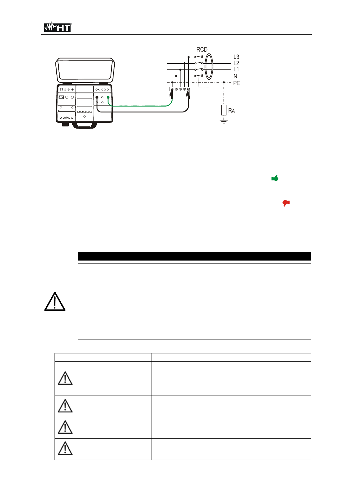
FULLTEST 3
Figure 26: Connection of test leads to tested wiring for LOOPL/PE measurement
7) READY message will appear when mains voltage UL/N (LOOP L/N) or UL/PE (LOOP L/PE) within
100 265 V or UL/L (LOOP L/L) within 100 460 V is present. Carry out the measurement by
pressing the START button.
8) Test result (loop impedance) will be displayed in green colour equipped with green symbol and
with beep-beep sound if measured/calculated ISC corresponds to entered limit mode and other
entered parameters. If measured/calculated ISC does not correspond to entered limit mode and
other entered parameters the result will be displayed in red colour equipped with red symbol
and with longer beep sound. See the display outlook with test result on the figure 22.
9) Save the test result by pressing the SAVE hard button twice, for further instructions see the
“MEMORIZING EXAMPLE” section.
10) Press the EXIT hard key to clear displayed result, actual input voltage UL/L or UL/N or UL/PE will
start to be displayed again.
CAUTION
In case voltage UL/N (LOOP L/N measurement) or voltage UL/PE (LOOP L/PE
measurement) within required range 100 265 V is present at L/N/PE test
terminals (also displayed) but there is no READY message displayed, check if
energizing socket is correctly earthed!
In case voltage U
V is present at L/N test terminals (also displayed) but there is no READY
L/L (LOOP L/L measurement) within required range 100 460
message displayed, check if energizing socket is correctly earthed!
If limit mode STD is selected (result is not evaluated), then the result will be
The following specific information can be shown on the display during the measurement:
displayed in white colour.
Information displayed Description
Input voltage UL/N or UL/PE out of required range 100
265 V (L/N or L/PE measurement) or out of required range
VOLTAGE OUT OF RANGE
173 460 V (L/L measurement) after pressing the START
key.
FUSE F3!
Fuse F3 is blown.
Internal load is overheated.
HOT!
Wait to cool it down!
Input voltage failed during the measurement (disconnection
MEASUREMENT FAILED!
of test leads, installation fuse tripped etc.)
EN - 38
Page 40
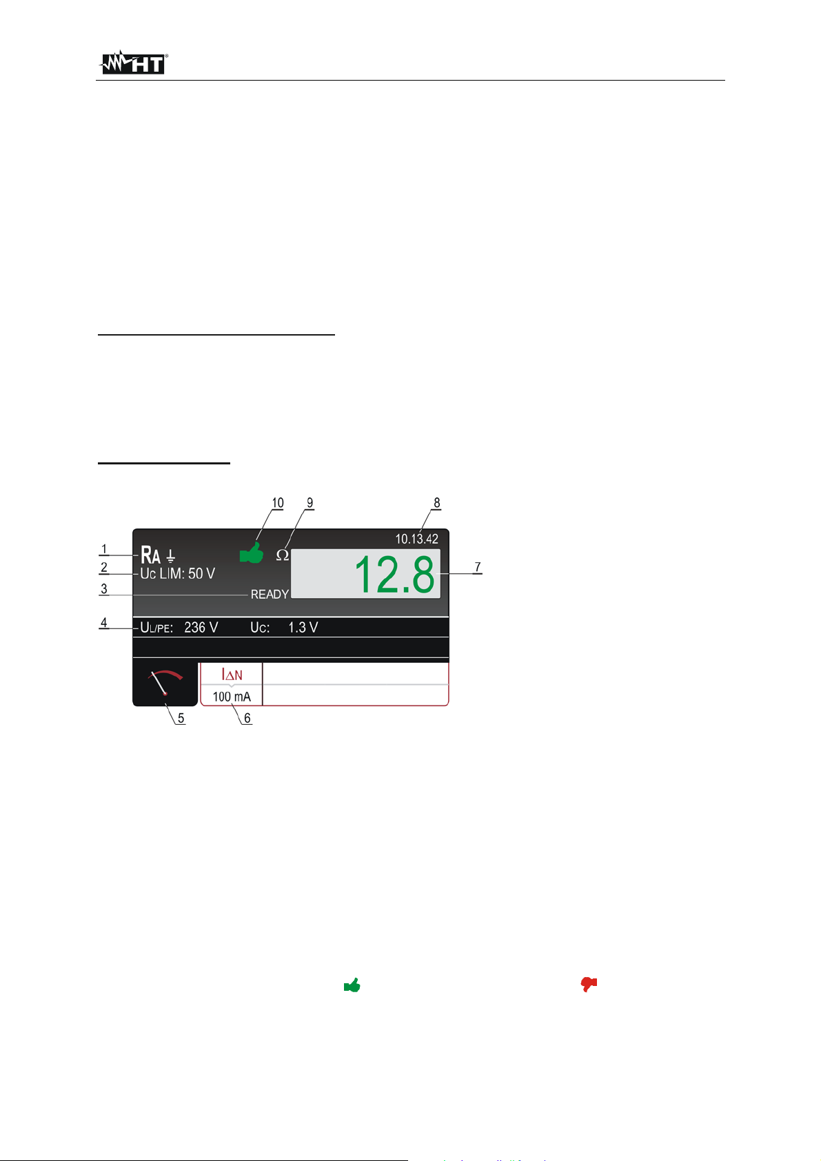
FULLTEST 3
5.7. GLOBAL EARTH RESISTANCE / CONTACT VOLTAGE (RA)
• According to EN 60204-1, the conditions for protection against electric shock in installations with
automatic disconnection of mains voltage are:
• Measurement or evaluation of fault loop impedance and testing the over-current protection device
involved in the fault loop.
• Limit values are shown in the Table 10 of EN 60204-1.
5.7.1. RA LIMIT VALUE CALCULATION
The global resistance RA should be lower than or equal to UC LIM / IN, where limit contact voltage UC
can be set to 25 or 50 V.
Example: Selected UC LIM = 50 V
Selected I
N = 300 mA
RA LIM = 166.7
How to select limit contact voltage UC LIM:
Press the MENU SETUP CONTACT VOL. touch-screen keys and select 25 V or 50 V.
5.7.2. RA DISPLAY EXPLANATION
Selectable parameter:
IN nominal differential current 10, 30, 100, 300, 500, 650 or 1000 mA
Figure 27: Display with RA test result
1 ..... Selected function.
2 ..... Selected limit contact voltage (25 or 50 V).
3 ..... READY message. It is displayed when mains voltage UL/PE within 100 ... 265 V is present.
4 ..... Sub-results, mains voltage UL/PE at which the measurement was carried out and contact voltage
UC at nominal differential current.
5 ..... Measurement screen touch-screen key.
6 ..... IN touch-screen key to select nominal differential current. Currently selected value is displayed in
the bottom of the key.
7 ..... Measurement result (in green colour - result OK, in red colour - result not OK).
8 ..... Real time clock (hh.mm.ss).
9 ..... Unit of the test result.
10 ... Measurement result status (symbol
in green colour - result OK, symbol in red colour - result
not OK).
EN - 39
Page 41
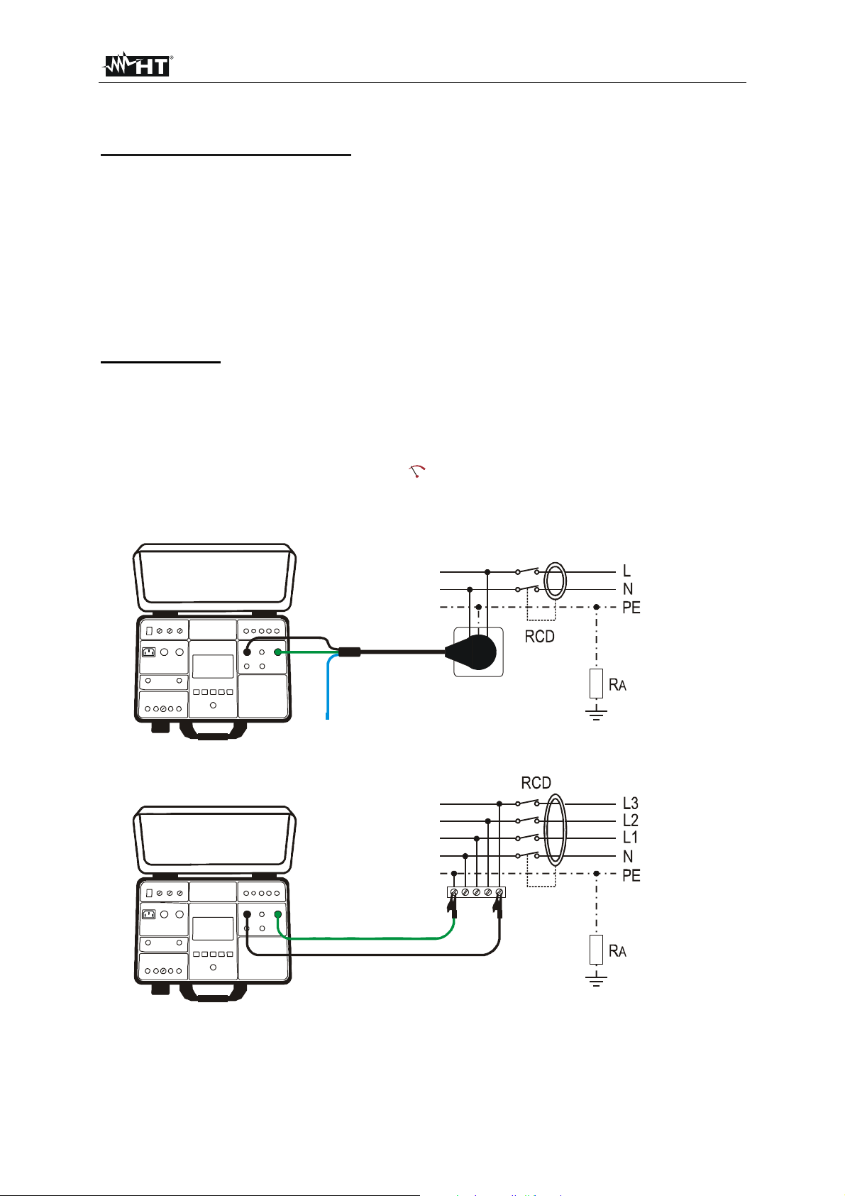
FULLTEST 3
5.7.3. RA MEASUREMENT
Measured quantities and display ranges:
Global earth resistance RA 0 2.000 (IN = 10 or 30 mA)
0 1.000 (IN = 100 mA)
0 300 (IN = 300 mA)
0 200 (IN = 500 mA)
0 150 (IN = 650 mA)
0 100 (IN = 1000 mA)
Mains voltage UL/PE 100 265 V AC
Contact voltage UC 0 100 V AC (UC LIM = 50 V)
0 50 V AC (UC LIM = 25 V)
Input requirements:
Mains voltage UL/PE (READY condition) 100 265 V AC
1) Select the RA measurement by pressing the FUNC hard key first.
2) Check selected nominal differential current (10, 30, 100, 300, 500, 650 and 1000 mA) and modify it
if needed by pressing the IN (6) touch-screen key first.
3) Select measurement screen by pressing the (5) touch-screen key and check all settings again.
4) Connect the test leads according to one of the figures below. READY message (3) will appear
when mains voltage UL/PE within 100 ... 265 V is present.
Figure 28: Connection of test cable to schuko socket
Figure 29: Connection of test leads to tested wiring
EN - 40
Page 42

FULLTEST 3
5) Carry out the measurement by pressing the START/STOP button. Test result will be displayed
after elapsing measurement time in green colour equipped with green
symbol and with beep-
beep sound if it is lower than or equal to limit value (see the explanation of limit value above). If the
result is higher than limit value, then it will be displayed in red colour equipped with red symbol
and with longer beep sound. See the display outlook with test result on the figure 27.
6) Save the test result by pressing the SAVE hard key twice, for further instructions see the
“MEMORIZING EXAMPLE” section.
7) Press the EXIT hard key to clear displayed result, actual input voltage UL/PE will start to be
displayed again.
CAUTION
In case voltage UL/PE within required range 100 265 V is present between L
and PE test terminals (also displayed) but there is no READY message
displayed, check if energizing socket is correctly earthed!
The following specific information can be shown on the display during the measurement:
Information displayed Description
Input voltage UL/PE out of required range 100 265 V
VOLTAGE OUT OF RANGE!
after pressing the START key.
CONTACT VOLTAGE > 50 V
or
CONTACT VOLTAGE > 25 V
MEASUREMENT FAILED!
FUSE F3!
HOT!
Contact voltage higher than selected limit value, probably
due to too high loop resistance.
Measurement current was interrupted either due to
disconnection of test leads or due to increase of loop
resistance.
Fuse F3 is blown.
Internal circuitry is overheated.
Wait to cool it down!
EN - 41
Page 43
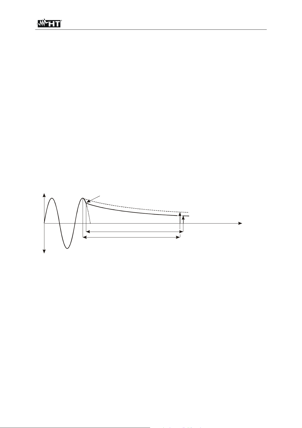
FULLTEST 3
)
(
)
5.8. RESIDUAL VOLTAGE (URES)
• What are residual voltages? Residual voltages are the voltages that remain present even after
switching off a machine or device. This can be caused e.g. by built in capacitors or subsequent
generators. This measurement is performed by using the URES function.
• According to EN 60204-1, accessible live parts connected to dangerous voltage must discharge
within 5 seconds (permanently connected machines) or within 1 second (plugged-in machines) down
to 60 V. Proof of this must be given through tests.
• In the event of non-compliance, additional measures (discharge devices, warning information, covers
etc.) according to EN 60204-1 must be taken.
• With FULLTEST 3 tester the residual voltage can be measured 1 s or 5 s after switching off tested
machine. Measurement of residual voltage can be carried out in linear or non-linear mode, see the
section "EXPLANATION OF LINEAR MODE" or section "EXPLANATION OF NONLINEAR MODE".
5.8.1. EXPLANATION OF LINEAR MODE
In linear mode it is assumed there are only "linear" components involved in discharging process
(capacitors, resistors, inductors etc.) and therefore discharge characteristic is exponential, see the
diagram below.
In linear mode displayed result is scaled to peak value of input voltage in order to evaluate most critical
situation, see the figure below.
Coincidential switch off
at any mains voltage
U
U
correct value
RES
U (measured
RES
1s / 5s
t
1s / 5s
Figure 30: Discharge diagram in linear circumstances
For scaling of measured URES voltage Un of mains installation is needed, so it must be selected in prior
to the measurements.
How to select the nominal voltage Un:
Press the MENU SETUP NOMINAL VOL. touch-screen keys and select 230 V or 240 V. See the
chapter “6.5.4. NOMINAL VOLTAGE menu”.
In linear mode the FULLTEST 3 detects automatically two standard system voltages:
a) Selected nominal voltage Un = 230 V
230 V ............................ UIN = 230 V 10%
400 V ............................ UIN = 400 V 10%
b) Selected nominal voltage Un = 240 V:
240 V ............................ UIN = 240 V 10%
415 V ............................ UIN = 415 V 10%
EN - 42
Page 44

FULLTEST 3
)
To include standard mains over-voltage, the measured residual voltage is scaled to peak value of max.
possible mains over-voltage, i.e.:
a) Selected nominal voltage Un = 230 V
Up = 230 V × 1.1 × 1.41 = 358 V ....................... system voltage 230 V is recognized
Up = 400 V × 1.1 × 1.41 = 620 V ....................... system voltage 400 V is recognized
b) Selected nominal voltage Un = 240 V
Up = 240 V × 1.1 × 1.41 = 372 V ....................... system voltage 240 V is recognized
Up = 415 V × 1.1 × 1.41 = 644 V ....................... system voltage 415 V is recognized
If actual mains voltage differs from nominal system voltage more than 10%, the FULLTEST 3 scales
the result to peak value of actual input voltage.
Example 1 (Un = 230 V):
IN = 173 V (the value differs more than 10% from 230 V), result is scaled to 173 V × 1.41 = 244 V
U
Example 2 (Un = 230 V):
U
IN = 209 V (the value differs less than 10% from 230 V), result is scaled to 230 V × 1.1 × 1.41 = 358 V
5.8.2. EXPLANATION OF NONLINEAR MODE
In non-linear mode it is assumed there are also "non-linear" or unknown components involved in
discharge process (relays, gas lamps etc.) and therefore discharge characteristic is non-exponential or it
is unpredictable, see the diagram below.
Coincidential switch off
U
at any mains voltage
Some relay may be switched off
U (measured
RES
t1s / 5s
Figure 31: Discharge diagram in non-linear circumstances
In this case result can not be scaled to peak value, so it must be assured that switch off occurs at max.
input voltage i.e. at pick value (± 5%), otherwise measured result is not relevant. Measured value is
then registered and evaluated.
EN - 43
Page 45

FULLTEST 3
5.8.3. URES DISPLAY EXPLANATION
Selectable parameters:
MODE - measurement mode LINEAR or NONLINEAR
CON - connection INT (measurement on internal components) or PLUG (measurement on
1P/3P plug)
LIMIT t - limit time 1 s or 5 s
Figure 32: Display with URES test result
1 ..... Selected function.
2 ..... Input voltage UIN and trigger voltage UTRIG.
3 ..... Measurement screen touch-screen key.
4 ..... MODE touch-screen key to select measurement mode (LINEAR or NONLINEAR). Currently
selected mode is displayed on the bottom of the key.
5 ..... CON (connection) touch-screen key to select measurement connection (INT or PLUG). Currently
selected connection is displayed on the bottom of the key.
6 ..... LIMIT t touch-screen key to select limit time (1 s or 5 s), valid for internal measurement only.
Currently selected limit value is displayed on the bottom of the key.
7 ..... Measurement result (in green colour - result OK, in red colour - result not OK).
8 ..... Real time clock (hh.mm.ss).
9 ..... Unit of the test result. As measured URES voltage may be alternating or direct there is an
appropriate information AC or DC added to the unit.
10 ... Measurement result status (symbol in green colour - result OK, symbol in red colour - result
not OK).
5.8.4. TRIGGER CONDITIONS
The instrument recognizes disconnection of mains voltage on TRIG input (INT measurement) or on
URES input (PLUG measurement) when one of the following two conditions occurs:
If mean value of rectified input voltage drops down with a slope of at least 25 V / s (mean value
measured each period), then trigger is activated and the measurement starts to run.
This condition will occur for example if AC or DC input voltage starts to decrease.
Momentary value of current half period is compared with momentary value of previous half period
(the same polarity). If there is a difference higher than 10%, then trigger is activated and the
measurement starts to run.
This condition will occur for example if AC voltage changes to DC.
The above two conditions are active on URES input in PLUG mode and on UTRIG input in INT mode.
EN - 44
Page 46

FULLTEST 3
5.8.5. URES MEASUREMENT
Measured quantities and display ranges:
Residual voltage on power plug URES 10 460 V AC or 10 650 V DC
Residual voltage on internal components URES 10 460 V AC or 10 650 V DC
Input requirements:
Input voltage UIN (READY condition in PLUG mode) 43 460 V AC
Trigger voltage UTRIG (READY condition in INT mode) 100 460 V AC
1) Select URES function by pressing the FUNC key first.
2) Check selected mode and modify it if needed by pressing the MODE (4) touch-screen key first.
3) Check selected connection and modify it if needed by pressing the CON (5) touch-screen key first.
INT 4-WIRE mode is selected:
4) Check selected limit time and modify it if needed by pressing the LIMIT t (6) touch-screen key first.
5) Select measurement screen by pressing the (3) touch-screen key and check all settings again.
6) Connect test leads according to one of the figures below.
Figure 33: Connection of test leads in URES INT measurement on 1P/3P plugged machines
Figure 34: Connection of test leads in URES INT measurement on fixed connected machines
7) READY, DISCONNECT UUT message will appear when UTRIG voltage within required range 100
460 VAC is present. Carry out the measurement by disconnecting UUT. Disconnection of UUT
according to the figure 33 means disconnection of multiple plug adapter. Disconnection of UUT
according to the figure 34 means turning off mains switch.
EN - 45
Page 47

FULLTEST 3
8) Test result will be displayed in green colour equipped with green symbol and with beep-beep
sound if it is lower than or equal to 60 VRMS (may be AC or DC, see the unit). If the result is higher
than 60 VRMS, then it will be displayed in red colour equipped with red symbol and with longer
beep sound. See the display outlook with test result on the figure 32.
9) Save the test result by pressing the SAVE hard key twice, for further instructions see the
“MEMORIZING EXAMPLE” section.
10) Press the EXIT hard key to clear displayed result, actual input voltage UIN and actual trigger
voltage UTRIG will start to be displayed again.
PLUG/1s mode is selected:
4) Select measurement screen by pressing the (3) touch-screen key and check all settings again.
5) Connect test leads according to the figure below.
t1 s
RES
<
Figure 35: Connection of test leads in URES PLUG measurement
6) READY, DISCONNECT UUT message will appear when input voltage UIN within required range
100 460 VAC is present. Carry out the measurement by disconnecting UUT. Disconnection of
UUT according to the figure 35 means disconnection of multiple plug adapter.
7) Test result will be displayed in green colour equipped with green symbol and with beep-beep
sound if it is lower than or equal to 60 VRMS (may be AC or DC, see the unit). If the result is higher
than 60 VRMS, then it will be displayed in red colour equipped with red symbol and with longer
beep sound. See the display outlook with test result on the figure 32.
8) Save the test result by pressing the SAVE hard key twice, for further instructions see the
“MEMORIZING EXAMPLE” section.
9) Press the EXIT hard key to clear displayed result, actual input voltage U
IN will start to be displayed
again.
CAUTION
Do not use the START button in this function, it has no function!
EN - 46
Page 48
FULLTEST 3
The following specific information can be shown on the display during the measurement:
Information displayed Description
LOW TRIGGER VOLTAGE
Mains voltage was disconnected at too low
momentary voltage (< 20% of peak value). The
message may appear in LINEAR mode only.
Repeat the measurement (connect and disconnect the
UUT again)!
LOW SWITCH-OFF VOLTAGE
Mains voltage was not disconnected close enough to
peak value (Up ± 5%) so the result would be irelevant
anyway. The message may appear in NONLINEAR
mode only.
Repeat the measurement (connect and disconnect the
UUT again)!
EN - 47
Page 49
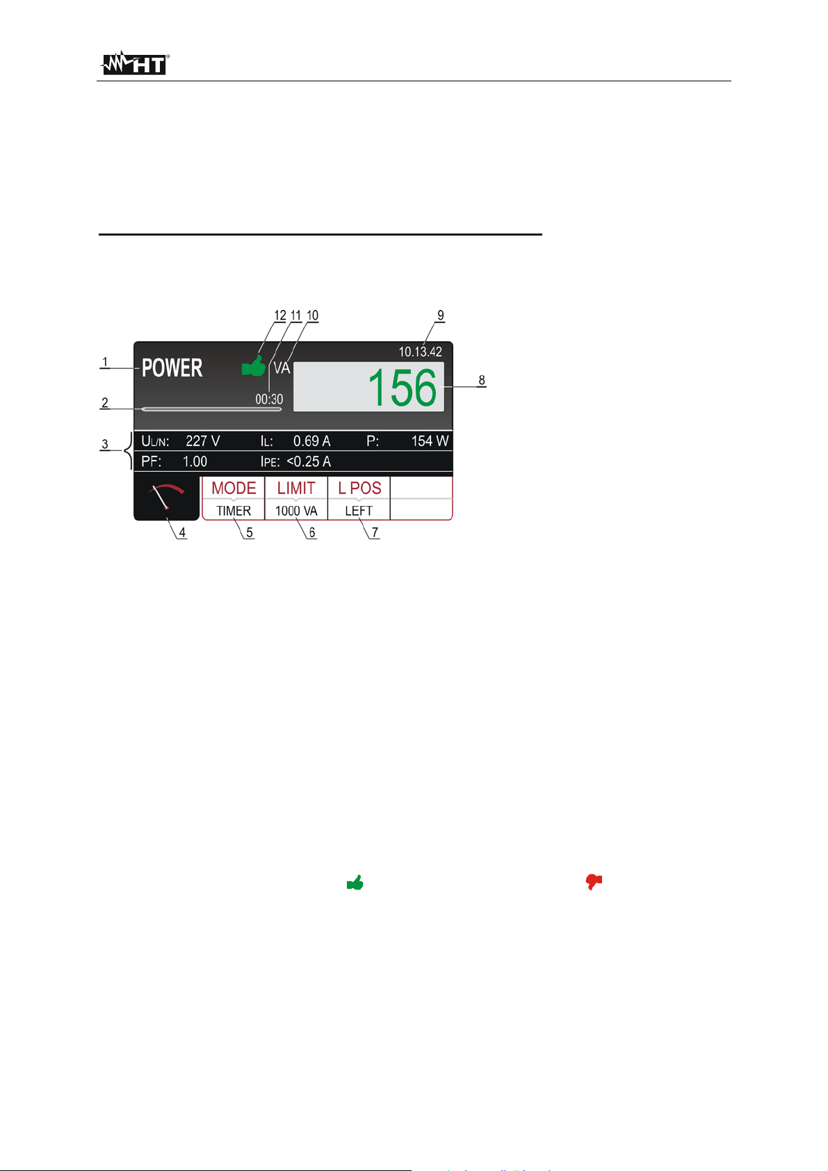
FULLTEST 3
5.9. POWER (POWER)
Measured appliance is supplied by mains voltage applied to schuko test socket. Switching the voltage
on/off as well as selection of phase position is done by internal switch of the tester.
5.9.1. POWER DISPLAY EXPLANATION
Adjustable/selectable parameters:
TIMER - measurement time 00:05 60:00, resolution 1 s
LIMIT - limit value of apparent power 6 VA 5.06 kVA
L POS - position of phase terminal on schuko socket LEFT or RIGHT
Figure 36: Display with POWER test result
1 ..... Selected function.
2 ..... Progress bar. It follows measurement time during the measurement.
3 ..... Two lines reserved for sub-results as follows: Mains voltages UL/N, Load current IL, Real power P,
Power factor PF and Leakage current IPE.
4 ..... Measurement screen touch-screen key.
5 ..... TIMER touch-screen key to adjust measurement time. Currently selected measurement time is
displayed on the bottom of the key.
6 ..... LIMIT touch-screen key to select limit apparent power. Currently selected value is displayed on the
bottom of the key.
7 ..... L POS touch-screen key to select the position of phase terminal on schuko socket during the
measurement. Currently selected position is displayed on the bottom of the key.
8 ..... Measurement result (in green colour - result OK, in red colour - result not OK).
9 ..... Real time clock (hh.mm.ss).
10 ... Unit of the test result.
11 ... Set measurement time.
12 ... Measurement result status (symbol in green colour - result OK, symbol in red colour - result
not OK).
EN - 48
Page 50
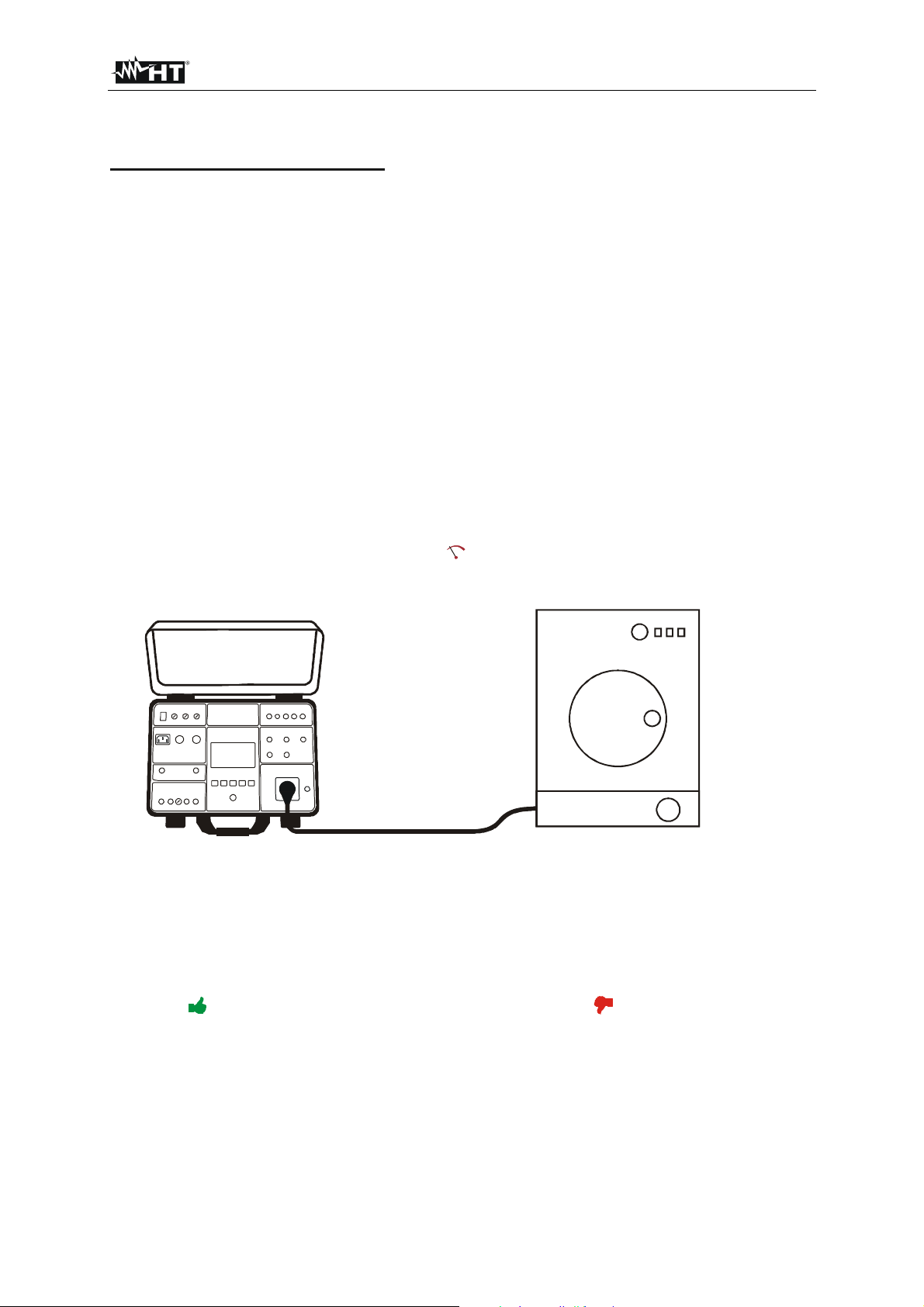
FULLTEST 3
5.9.2. POWER MEASUREMENT
Measured quantities and display ranges:
Apparent power PAPP 0 5.06 kVA
Real power P 0 5.06 kVA
Mains voltage UL/N 195 253 V
Load current IL 0 20 A
Power factor PF 0 1
Leakage current I
PE 0.25 mA 10 A
1) Select POWER function by pressing the FUNC hard key first.
2) Check selected measurement time and modify it if needed by pressing the MODE (5) touch-screen
key first. Four independent preset measurement times are available for quicker operations. Select
the closest one and modify it by using the + and ― touch screen keys if needed.
3) Check selected limit apparent power and modify it if needed by pressing the LIMIT (6) touch-
screen key first. Four independent preset limit values are available for quicker operations. Select
the closest one and modify it by using the + and ― touch screen keys if needed.
4) Check selected position of phase terminal on schuko socket by pressing the L POS (7) touch-
screen key. If LEFT position is selected then phase potential is connected to the left terminal of
schuko socket and vice versa.
5) Select measurement screen by pressing the
(4) touch-screen key and check all settings again.
6) Connect the UUT to schuko socket according to the figure below.
Figure 37: Connection of UUT to schuko test socket
7. Start the measurement by pressing the START/STOP button. The measurement will start to run
and will be stopped after pressing the START/STOP button again or after elapsing set
measurement time.
Test result (apparent power) will be currently displayed in green colour if it is lower than or equal to
set limit value or in red colour if it is higher than set limit value. Final result will be equipped with
green
symbol and with beep-beep sound if it is OK or with red symbol and with longer beep
sound if it is not OK. See the display outlook with test result on the figure 36.
8) Save the test result by pressing the SAVE hard key twice, for further instructions see the
“MEMORIZING EXAMPLE” section.
EN - 49
Page 51

FULLTEST 3
CAUTION
Measurement at both phase positions (phase at left terminal and phase at
right terminal) must be carried out when leakage current IPE is measured and
the highest value must be evaluated.
Switch on the UUT in order full power of the unit and total leakage current to
be measured!
In case of overloaded test socket the fuse F1 or F2 (both T16A/250V) may
blow.
Do not use test schuko socket except for measurement purpose!
The following specific information can be shown on the display during the measurement:
Information displayed Description
Leakage current IPE is higher than 3.5 mA what may be
dangerous for the operator. The message will appear
IPE > 3.5 mA
always when the current exceeds the 3.5 mA threshold and
will automatically disappear after 10 s. For more obvious
warning the message is accompanied with audio beep-
beep signal.
IPE CURRENT OVERRANGE!
IL CURRENT OVERRANGE!
If IPE current is higher than 10 A for 10 s, the measurement
will be stopped and this message will appear.
If IL current is higher than 16 A for 10 s, the measurement
will be stopped and this message will appear.
EN - 50
Page 52
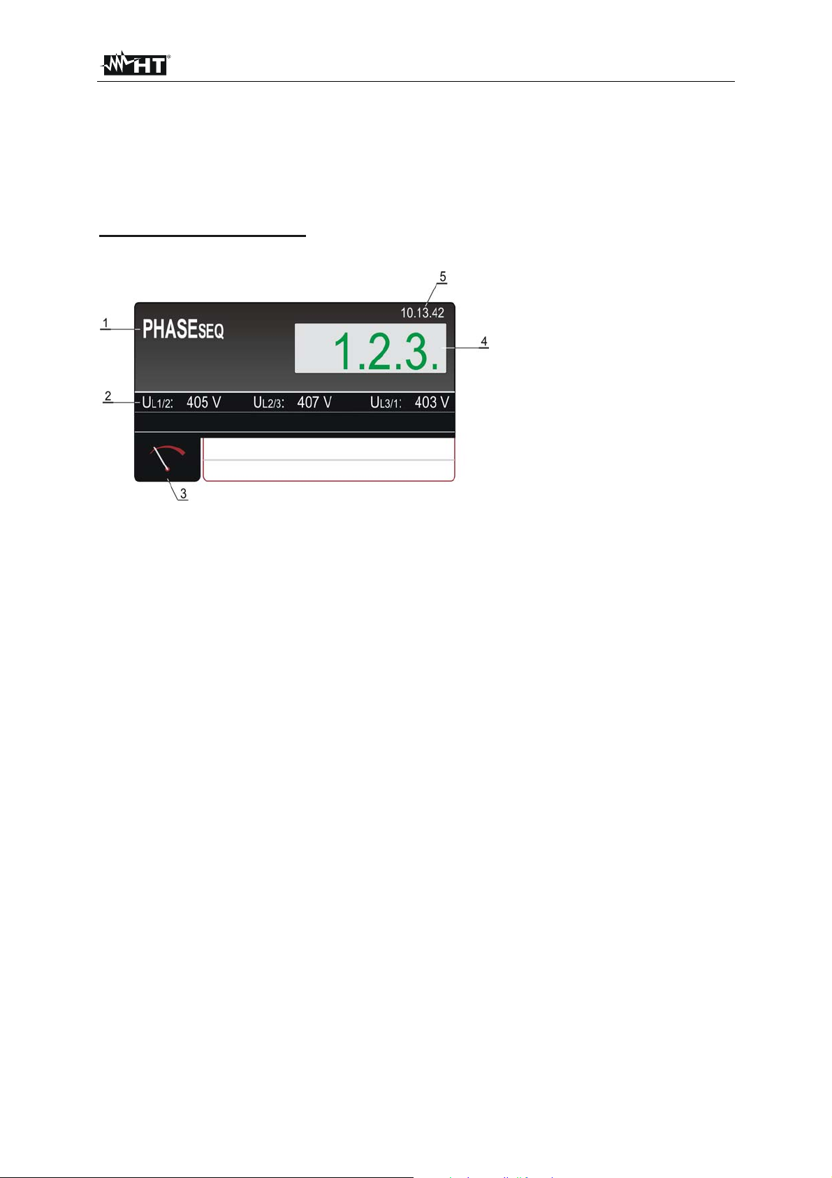
FULLTEST 3
5.10. PHASE SEQUENCE (PHASESEQ)
Correct phase sequence is important when e.g. 3-phase machines with mechanical rotation are
connected to 3-phase mains installation.
5.10.1. PHASE SEQUENCE DISPLAY EXPLANATION
Adjustable/selectable parameters:
There are no adjustable/selectable parameters available!
Figure 38: Display with PHASE SEQUENCE test result
1 ..... Selected function.
2 ..... Measurement sub-results as follows: Phase-to-phase voltage UL1/2, phase-to-phase voltage UL2/3,
phase-to-phase voltage UL3/1.
3 ..... Measurement screen touch-screen key.
4 ..... Measurement result (in green colour - result OK, in red colour - result not OK).
5 ..... Real time clock (hh.mm.ss).
EN - 51
Page 53

FULLTEST 3
5.10.2. PHASE SEQUENCE MEASUREMENT
Measured quantities and display ranges:
Phase sequence 1.2.3. or 2.1.3.
Phase-to-phase voltage UL1/2 360 460 V
Phase-to-phase voltage UL2/3 360 460 V
Phase-to-phase voltage UL3/1 360 460 V
1) Select the PHASESEQ function by pressing the FUNC hard key first.
2) Connect the test leads to tested socket/wiring according to the figure below.
Figure 39: Connection of test leads in PHASE SEQUENCE measurement
3) Carry out the measurement by pressing the START button. The measurement will be done and
test result will be displayed in green colour equipped and with beep-beep sound if it is in
accordance with referential direction (1.2.3.). If the result is not in accordance with referential
direction (2.1.3.) then it will be displayed in red colour equipped and with longer beep sound. See
the display outlook with test result on the figure 38.
4) Save the test result by pressing the SAVE hard key twice, for further instructions see the
“MEMORIZING EXAMPLE” section.
5) Press the EXIT hard key to clear displayed result, actual input voltages UL1/2, UL2/3, UL3/1 will start
to be displayed again.
The following specific information can be shown on the display during the measurement:
Information displayed Description
VOLTAGE OUT OF RANGE
One or more phase-phase voltages are out of required
range (360 460 V).
At least one of measured phases was disconnected during
1.1.X
the measurement.
Connect all three phases and repeat the measurement.
EN - 52
Page 54
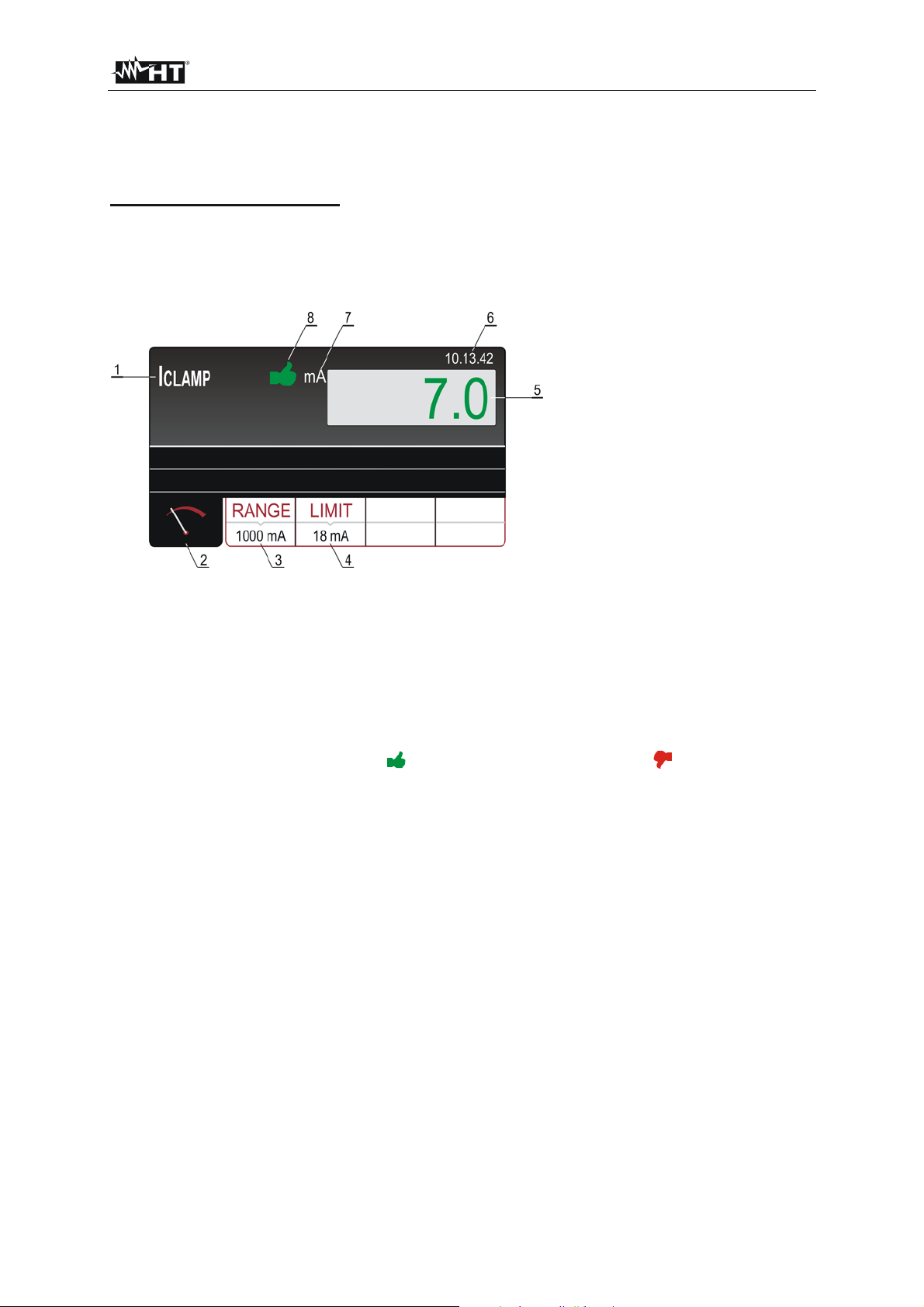
FULLTEST 3
5.11. CURRENT MEASUREMENT USING CURRENT CLAMP (ICLAMP)
5.11.1. ICLAMP DISPLAY EXPLANATION
Adjustable/selectable parameters:
RANGE - measurement range 1000 mA, 100 A or 1000 A
LIMIT - limit value 0.1 1000 mA (range 1000 mA)
0.1 100.0 A (range 100.0 A)
1 1000 A (range 1000 A)
Figure 40: Display with ICLAMP test result
1 ..... Selected function.
2 ..... Measurement screen touch-screen key.
3 ..... RANGE touch-screen key to select measurement range (0 1000 mA, 0 100 A or 0 1000 A).
4 ..... LIMIT touch-screen key to select limit current value inside each measurement range.
5 ..... Measurement result (in green colour - result OK, in red colour - result not OK).
5 ..... Real time clock (hh.mm.ss).
6 ..... Measurement result status (symbol in green colour - result OK, symbol in red colour - result
not OK).
EN - 53
Page 55

FULLTEST 3
5.11.2. ICLAMP MEASUREMENT
Measured quantities and display ranges:
Clamp current ICLAMP 0 1000 mA (range 1000 mA)
0 100 A (range 100 A)
0 1000 A (range 1000 A)
1) Select I
CLAMP function by pressing the FUNC hard key first.
2) Check selected measurement range and modify it if needed by pressing the RANGE (3) touch-
screen key first.
3) Check selected limit current and modify it if needed by pressing the LIMIT (4) touch-screen key
first. Four independent preset limit values are available for quicker operations. Select the closest
one and modify it by using the + and ― touch screen keys if needed.
4) Select measurement screen by pressing the (4) touch-screen key and check all settings again.
5) Connect current clamp to measured wiring according to the figure below.
I
L
I
PE
Load
Figure 41: Connection of current clamp in ICLAMP measurement
6) Start the measurement by pressing the START/STOP button. The measurement will start to run
and will be stopped after pressing the START/STOP button again. Measurement result will be
currently displayed in green colour if it is lower than or equal to set limit value or in red colour if it is
higher than set limit value. Final result will be equipped with green
sound if it is OK or with red
symbol and with longer beep sound if it is not OK. See the display
symbol and with beep-beep
outlook with test result on the figure 40.
7) Save the test result by pressing the SAVE hard key twice, for further instructions see the
“MEMORIZING EXAMPLE” section.
CAUTION
Max input voltage is 10 V, one terminal is grounded!
Measurement time is limited to 60 min!
EN - 54
Page 56
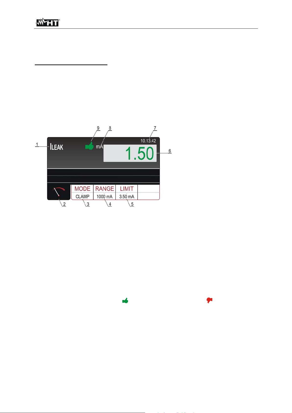
FULLTEST 3
5.12. LEAKAGE CURRENT (ILEAK)
5.12.1. LEAKAGE DISPLAY EXPLANATION
Adjustable/selectable parameters:
MODE - measurement mode CLAMP or SOCKET
LIMIT - leakage current limit value 0.1 100.0 mA, 101 1000 mA (CLAMP mode, range 1000 mA)
0.1 100.0 A (CLAMP mode, range 100.0 A)
1 1000 A (CLAMP mode, range 1000 A)
0.01 19.99 mA, 20.0 49.9 mA, 0.05 0.99 A, 1.0 10.0 A
(SOCKET mode)
RANGE - clamp measurement range 1000 mA, 100.0 A or 1000 A
L POS - phase position LEFT or RIGHT
Figure 42: Display with ILEAK test result in CLAMP mode
1 ..... Selected function.
2 ..... Measurement screen touch-screen key.
3 ..... MODE touch-screen key to select measurement mode (SOCKET or CLAMP). Currently selected
mode is displayed on the bottom of the key.
4 ..... RANGE touch-screen key to select the CLAMP measurement range. Currently selected range is
displayed on the bottom of the key.
5 ..... LIMIT touch-screen key to select limit leakage current. Currently selected value is displayed on the
bottom of the key.
6 ..... Measurement result (in green colour - result OK, in red colour - result not OK).
7 ..... Real time clock (hh.mm.ss).
8 ..... Unit of the test result.
9 ..... Measurement result status (symbol in green colour - result OK, symbol in red colour - result
not OK).
EN - 55
Page 57

FULLTEST 3
Figure 43: Display with ILEAK test result in SOCKET mode
1 ..... Selected function.
2 ..... Sub-result, mains voltage UL/N.
3 ..... Measurement screen touch-screen key.
4 ..... MODE touch-screen key to select measurement mode (SOCKET or CLAMP). Currently selected
mode is displayed on the bottom of the key.
5 ..... LIMIT touch-screen key to select limit leakage current. Currently selected value is displayed on the
bottom of the key.
6 ..... L POS touch-screen key to select the position of phase terminal on schuko socket during the
measurement. Currently selected position is displayed on the bottom of the key.
7 ..... Measurement result (in green colour - result OK, in red colour - result not OK).
8 ..... Real time clock (hh.mm.ss).
9 ..... Unit of the test result.
10 ... Measurement result status (symbol in green colour - result OK, symbol in red colour - result
not OK).
EN - 56
Page 58
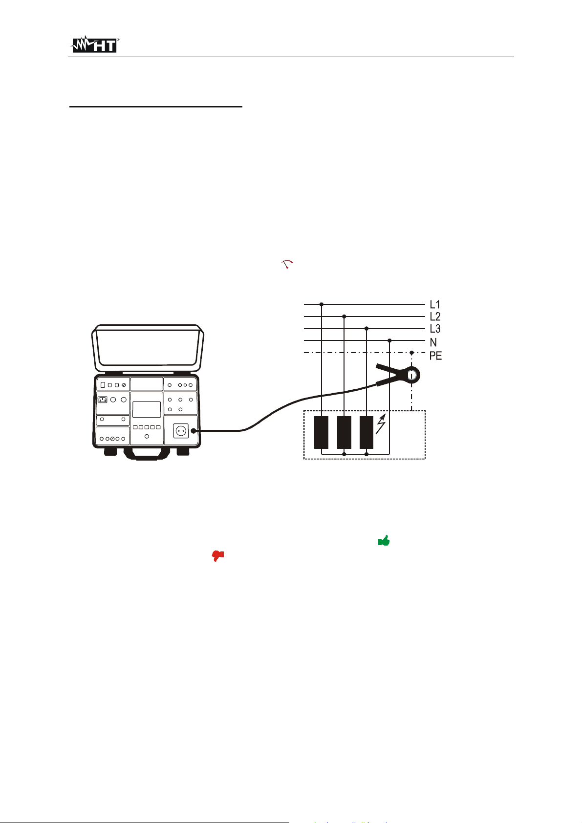
FULLTEST 3
5.12.2. LEAKAGE CURRENT MEASUREMENT USING CURRENT CLAMP
Measured quantities and display ranges:
Leakage current ILEAK measured by clamp 0 1000 mA (1000 mA range)
0 100 A (100 A range)
0 1000 A (1000 A range)
1) Select I
LEAK function by pressing the FUNC hard key first.
2) Select CLAMP mode by pressing the MODE touch-screen key first.
3) Check selected measurement range and modify it if needed by pressing the RANGE (4) touch-
screen key first.
4) Check selected limit leakage current by pressing the LIMIT (5) touch-screen key first. Four
independent limit values are available for quicker operations. Select the closest one and modify it
by using the + and ― touch screen keys if needed.
5) Select measurement screen by pressing the
touch-screen key and check all settings again.
6) Connect the current clamp to measured wiring according to the figure below.
IPE
Load
Figure 44: Connection of current clamp in ILEAK measurement, CLAMP mode
7) Start the measurement by pressing the START/STOP button. The measurement will start to run
and will be stopped after pressing the START/STOP button again. Measurement result will be
currently displayed in green colour if it is lower than or equal to set limit value or in red colour if it is
higher than set limit value. Final result will be equipped with green symbol and with beep-beep
sound if it is OK or with red symbol and with longer beep sound if it is not OK. See the display
outlook with test result on the figure 42.
8) Save the test result by pressing the SAVE hard key twice, for further instructions see the
“MEMORIZING EXAMPLE” section.
EN - 57
Page 59
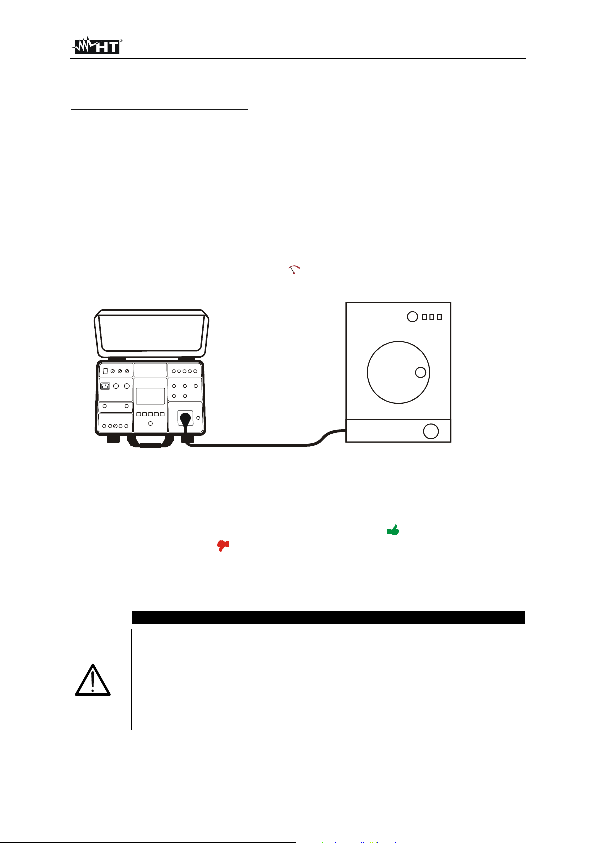
FULLTEST 3
5.12.3. LEAKAGE CURRENT MEASUREMENT ON SCHUKO SOCKET
Measured quantities and display ranges:
Leakage current IPE on schuko socket 0.25 mA 10 A
Mains voltage UL/N 195 253 V
1) Select ILEAK measurement by pressing the FUNC hard key first.
2) Select SOCKET mode by pressing the MODE touch-screen key first.
3) Check selected limit leakage current by pressing the LIMIT (5) touch-screen key first. Four
independent limit values are available for quicker operations. Select the closest one and modify it
by using the + and ― touch screen keys if needed.
4) Check selected position of phase terminal on schuko socket by pressing the L POS (6) touch-
screen key. If LEFT position is selected then phase potential is connected to left terminal of schuko
socket and vice versa.
5) Select measurement screen by pressing the touch-screen key and check all settings again.
6) Connect the UUT to schuko socket according to the figure below.
Figure 45: Connection of the UUT in ILEAK measurement, SOCKET mode
7) Start the measurement by pressing the START/STOP button. The measurement will start to run
and will be stopped after pressing the START/STOP button again. Measurement result will be
currently displayed in green colour if it is lower than or equal to set limit value or in red colour if it is
higher than set limit value. Final result will be equipped with green
symbol and with beep-beep
sound if it is OK or with red symbol and with longer beep sound if it is not OK. See the display
outlook with test result on the figure 43.
8) Save the test result by pressing the SAVE hard key twice, for further instructions see the
“MEMORIZING EXAMPLE” section.
CAUTION
Measurement at both phase positions (phase at left terminal and phase at
right terminal) must be carried out and the highest value must be evaluated.
Switch on the UUT in order total leakage current to be measured!
In case of overloaded test socket the fuse F1 or F2 (both T16A/250V) may
blow.
Do not use test schuko socket except for measurement purpose!
Measurement time (CLAMP and SOCKET) is limited to 60 min!
EN - 58
Page 60

FULLTEST 3
The following specific information can be shown on the display during the measurement:
Information displayed Description
IPE CURRENT OVERRANGE!
IL CURRENT OVERRANGE!
If IPE current is higher than 10 A for 10 s, the measurement
will be stopped and this message will appear.
If IL current is higher than 16 A for 10 s, the measurement
will be stopped and this message will appear.
EN - 59
Page 61

FULLTEST 3
6. MENU FUNCTIONS
For further selection, entry and display of instrument’s settings press the MENU hard key, the following
MAIN MENU will appear.
MAIN MENU
MEMORY LANGUAGE SETUP
OPERATOR TESTER INFO
SOUND
Figure 46: MAIN MENU
Press wished submenu touch-screen key for further settings.
6.1. MEMORY menu
MEMORY
USBCLEARMEM INFO
Figure 47: MEMORY menu
6.1.1. MEMORY INFO menu
MEMORY INFO
OCCUPIED
70
Figure 48: MEMORY INFO menu
Display of number of occupied and total memory locations. Each saved test result occupies one
memory location.
TOTAL
999
EN - 60
Page 62
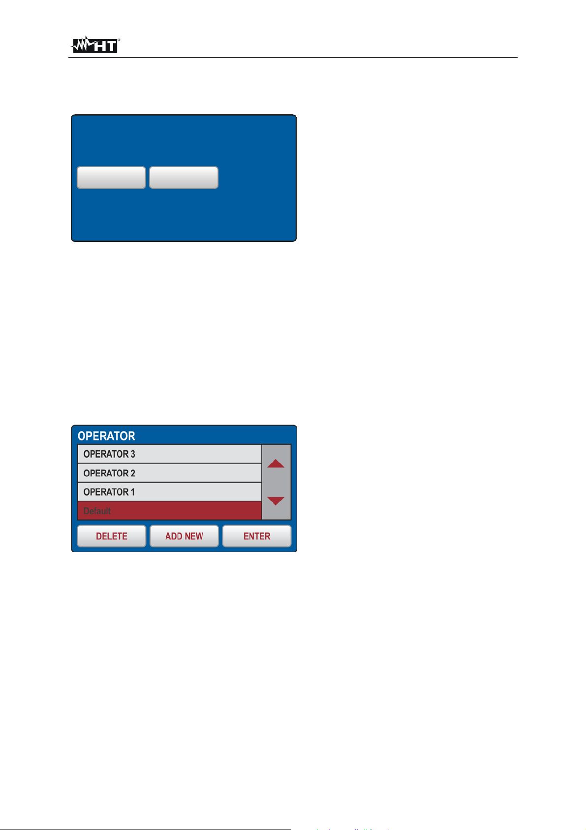
FULLTEST 3
In order to clear saved results the CLEAR menu shall be used.
6.1.2. CLEAR menu
CLEAR
TOTAL
LAST RESULT
Figure 49: CLEAR menu
The whole memory (TOTAL) or only the last saved result (LAST RESULT) can be cleared. If the last
result is cleared, then the result saved before the last one become to be the last and can be cleared too
etc. Confirm clearing operation by pressing the YES touch-screen key.
6.1.3. USB menu
In order to transfer stored data to USB memory drive or to printer or to PC the USB menu shall be used.
Insert the USB drive into USB2 or USB3 slot then press the USB touch-screen key. Confirm transferring
by pressing the YES key.
6.2. SELECT OPERATOR menu
Figure 50: OPERATOR menu
How to select wished operator:
- Check the list of available operators by using the ▼ and ▲ touch-screen keys (if there are more
than 4 operators entered).
- Select wished operator by pressing the operator’s touch-screen key, e.g. Default. Marked operator is
selected and will be used during the measurements.
- Press the ENTER touch-screen key to confirm the selection and to exit the OPERATOR menu, MAIN
MENU will be displayed again.
How to add a new operator:
- Open OPERATOR menu and press the ADD NEW touch-screen key, the following display will
appear.
EN - 61
Page 63
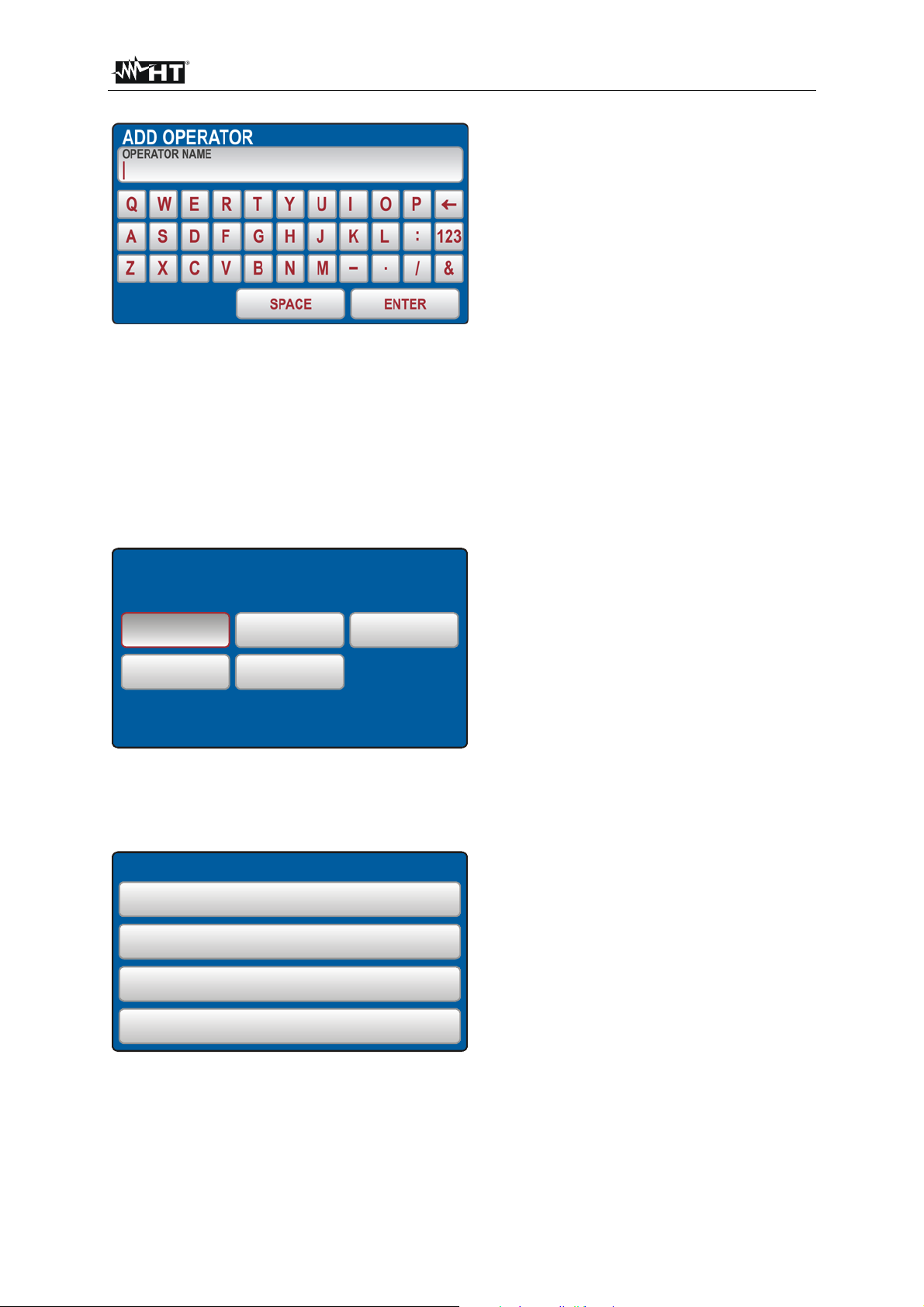
FULLTEST 3
Figure 51: ADD OPERATOR menu
- Create new operator’s name. Use the 123 / ABC key to select figure or character selection screen.
- Confirm entered name by pressing the ENTER touch-screen key. OPERATOR screen will appear
again and last entered operator will be selected.
How to delete an operator:
- Open OPERATOR menu, select the operator you wish to delete and press the DELETE touch-
screen key. Confirm the deletion by pressing the YES touch-screen key.
6.3. LANGUAGE menu
LANGUAGE
ENGLISH ITALIAN GERMAN
FRENCH SPANISH
Figure 52: LANGUAGE menu
Select wished language by pressing appropriate touch-screen key, the menu will turn to MAIN MENU.
6.4. TESTER INFO menu
TESTER INFO
FIRMWARE VERSION
B01.M01.V01
HARDWARE VERSION
1.00
SERIAL NUMBER
13110127
CATALOG NUMBER
FULLTST 3
Figure 53: TESTER INFO menu
TESTER INFO menu displays basic data of the tester like firmware version, hardware version, serial
number and catalog number.
EN - 62
Page 64
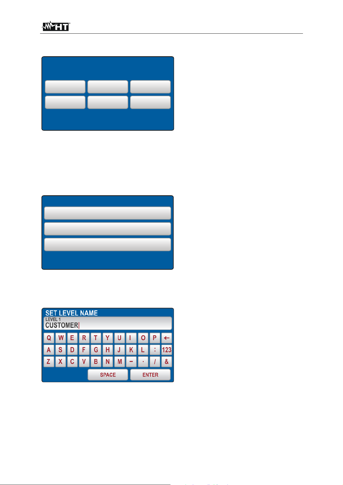
FULLTEST 3
6.5. SETUP menu
SETUP
LEVEL NAMES
DATE/TIME NOMINAL VOL.
SAFET INPUT RESETCONTACT VOL.
Figure 54: SETUP menu
6.5.1. LEVEL NAMES menu
Three levels are available when saving test results i.e. LEVEL1, LEVEL2 and LEVEL3. In production the
three levels are dedicated to CUSTOMER, LOCATION and MACHINE, but operator can rename them
freely for example to DEVICE, DEPARTMENT and LOCATION.
In order to do this the LEVEL NAMES menu shall be used.
LEVEL NAMES
LEVEL 1
CUSTOMER
LEVEL 2
LOCATION
LEVEL 3
MACHINE
Figure 55: LEVEL NAMES menu
Press the level touch-screen key you wish to rename for example LEVEL 1, the following menu will
appear.
Figure 56: SET LEVEL NAME menu
Modify existing name and confirm it by pressing the ENTER touch-screen key, the menu will turn to
LEVEL NAMES menu.
Repeat the operation for the other two levels if needed by following the same procedure.
EN - 63
Page 65

FULLTEST 3
6.5.2. LIMIT CONTACT VOLTAGE menu
This menu shall be used in order to select limit contact voltage which is used in RCD and in RA
measurements. The voltage may be either 25 or 50 V.
CONTACT VOL.
50 V25 V
Figure 57: CONTACT VOL. menu
Select wished limit contact voltage by pressing appropriate touch-screen key, the menu will turn to
SETUP menu.
In order to set date and time DATE/TIME menu shall be used.
6.5.3. DATE/TIME menu
Figure 58: DATE/TIME menu
Enter actual date and time by using the , and 0 ... 9 keys. Confirm it by pressing the ENTER
touch-screen key. Time starts to run on this confirmation.
6.5.4. RESET menu
There are many adjustable parameters in the FULLTEST 3 tester. If an operator due to any reason
wishes to reset all adjustable parameters to factory-set values, the operation can be done by using the
RESET menu.
Confirm RESET operation by pressing the YES touch-screen key or press the EXIT hard key to exit the
menu. Turn the tester off and on again by using the ON/OFF mains switch.
EN - 64
Page 66
FULLTEST 3
The following parameters have been reset.
Function Parameter
GENERAL - OPERATOR = Default
- LANGUAGE = ITALIAN
- CONTACT VOLTAGE = 50 V
- NOMINAL VOLTAGE = 230 V
- SAFETY INPUT = ENABLED
- SOUND = ON
RPE-2WIRE - Im NOM = 200 mA
- LIMIT value (200 mA) = 0.30
- MODE = MANUAL
- CAL (200 mA) = 0.00
- LIMIT value 1 (200 mA) = 0.30
- LIMIT value 2 (200 mA) = 1.00
- LIMIT value 3 (200 mA) = 5.00
- LIMIT value 4 (200 mA) = 50.0
- LMIT mode (25 A) = STANDARD
- LIMIT value (25 A, STANDARD limit mode) = 0.30
- LIMIT value 1 (25 A, STANDARD limit mode) = 0.30
- LIMIT value 2 (25 A, STANDARD limit mode) = 1.00
- LIMIT value 3 (25 A, STANDARD limit mode) = 5.00
- LIMIT value 4 (25 A, STANDARD limit mode) = 10.0
- LENGTH = 2 m
- LENGTH 1 = 2 m
- LENGTH 2 = 3 m
- LENGTH 3 = 10 m
- LENGTH 4 = 100 m
- SECTION = 1 mm
- SECTION 1 = 1 mm
- SECTION 2 = 2.5 mm
- SECTION 3 = 10 mm
- SECTION 4 = 35 mm
- MAT. = Cu
LINE = 0.100
- Z
LINE 1 = 0.100
- Z
LINE 2 = 0.300
- Z
- Z
LINE 3 = 0.500
LINE 4 = 1.000
- Z
- PROTECTION = MCB B
- I
N (any protection) = 6 A
N (any protection) 1 = 6 A
- I
- I
N (any protection) 2 = 16 A
- IN (any protection) 3 = 25 A
- I
N (any protection) 4 = 32 A
- TIMER = 3 s
- TIMER 1 = 3 s
- TIMER 2 = 10 s
- TIMER 3 = 30 min
- TIMER 4 = 60 min
- CAL (25 A) = 0.000
2
2
2
2
2
EN - 65
Page 67

FULLTEST 3
RPE-4WIRE
- LIMIT value (STANDARD limit mode) = 0.300
- MODE MANUAL
- LIMIT value 1 (STANDARD limit mode) = 0.300
- LIMIT value 2 (STANDARD limit mode) = 1.000
- LIMIT value 3 (STANDARD limit mode) = 5.00
- LIMIT value 4 (STANDARD limit mode) = 10.00
- LENGTH = 2 m
- LENGTH 1 = 2 m
- LENGTH 2 = 3 m
- LENGTH 3 = 10 m
- LENGTH 4 = 100 m
- SECTION = 1 mm
- SECTION 1 = 1 mm
- SECTION 2 = 2.5 mm
- SECTION 3 = 10 mm
- SECTION 4 = 35 mm
- MAT. = Cu
- Z LINE = 0.100
LINE 1 = 0.100
- Z
- Z
LINE 2 = 0.300
LINE 3 = 0.500
- Z
LINE 4 = 1.000
- Z
- PROTECTION = MCB B
- I
N (any protection) = 6 A
- I
N (any protection) 1 = 6 A
- I
N (any protection) 2 = 16 A
- IN (any protection) 3 = 25 A
- I
N (any protection) 4 = 32 A
- TIMER = 3 s
- TIMER 1 = 3 s
- TIMER 2 = 10 s
- TIMER 3 = 30 min
- TIMER 4 = 60 min
RISO - MODE = MANUAL
- Um
NOM = 500 V
- LIMIT value = 0.25 M
- TIMER = 5 s
- TIMER 1 = 5 s
- TIMER 2 = 10 s
- TIMER 3 = 1 min
- TIMER 4 = 10 min
- LIMIT value 1 = 0.25 M
- LIMIT value 2 = 0.30 M
- LIMIT value 3 = 1.00 M
- LIMIT value 4 = 2.00 M
2
2
2
2
2
EN - 66
Page 68
FULLTEST 3
DIELECTRIC - MODE = MANUAL
- UTEST NOM = 250 V
- LIMIT value = 1 mA
- CHAR = I
APP
- UTEST NOM 1 = 250 V
- UTEST NOM 2 = 1000 V
- U
TEST NOM 3 = 2500 V
- U
TEST NOM 4 = 3500 V
- RAMP TIMER = 10 s
- RAMP TIMER 1 = 10 s
- RAMP TIMER 2 = 30 s
- RAMP TIMER 3 = 1 min
- RAMP TIMER 4 = 10 min
- LIMIT value 1 = 1 mA
- LIMIT value 2 = 10 mA
- LIMIT value 3 = 50 mA
- LIMIT value 4 = 100 mA
RCD - TYPE = AC GEN
- I
N = 30 mA
- MEAS = t/IN
- POL = POS
- DELAY = 100 ms
- DELAY 1 = 100 ms
- DELAY 2 = 200 ms
- DELAY 3 = 300 ms
- DELAY 4 = 700 ms
LOOP - MODE = LOOP L/N
- LIMIT mode = STD
- Ib = 1 kA
- Ib 1 = 1 kA
- Ib 2 = 3 kA
- Ib 3 = 6 kA
- Ib 4 = 25 kA
- PROTECTION = MCB B
- I
N (any protection) = 6 A
- I
N (any protection) 1 = 6 A
- I
N (any protection) 2 = 16 A
- I
N (any protection) 3 = 25 A
N (any protection) 4 = 32 A
- I
- MAT. = Cu
- COATING = PVC
- SECTION = 1 mm
- SECTION 1 = 1 mm
- SECTION 2 = 2.5 mm
- SECTION 3 = 10 mm
- SECTION 4 = 35 mm
2
2
2
2
2
- N = 1
- N 1 = 1
- N 2 = 10
- N 3 = 50
- N 4 = 75
- T
SET = 0.2 s
RA - Nominal differential current IN = 30 mA
URES - CONNECTION = PLUG
- MODE = LINEAR
- LIMIT t = 5 s
EN - 67
Page 69

FULLTEST 3
POWER - TIMER = 10 s
- LIMIT apparent power = 6 VA
- L POS = RIGHT
- TIMER 1 = 10 s
- TIMER 2 = 30 s
- TIMER 3 = 1 min
- TIMER 4 = 10 min
- LIMIT apparent power 1 = 6 VA
- LIMIT apparent power 2 = 100 VA
- LIMIT apparent power 3 = 1.00 kVA
- LIMIT apparent power 4 = 5.06 kVA
PHASE ROTATION - None
ICLAMP - RANGE = 1000 mA
- LIMIT value (range 1000 mA) = 3.5 mA
- LIMIT value 1 (range 1000 mA) = 3.5 mA
- LIMIT value 2 (range 1000 mA) = 10.0 mA
- LIMIT value 3 (range 1000 mA) = 100 mA
- LIMIT value 4 (range 1000 mA) = 1000 mA
- LIMIT value (range 100.0 A) = 6.0 A
- LIMIT value 1 (range 100.0 A) = 6.0 A
- LIMIT value 2 (range 100.0 A) = 16.0 A
- LIMIT value 3 (range 100.0 A) = 50.0 A
- LIMIT value 4 (range 100.0 A) = 100.0 A
- LIMIT value (range 1000 A) = 6 A
- LIMIT value 1 (range 1000 A) = 6 A
- LIMIT value 2 (range 1000 A) = 160 A
- LIMIT value 3 (range 1000 A) = 500 A
- LIMIT value 4 (range 1000 A) = 1000 A
ILEAK - MODE = CLAMP
- RANGE = 1000 mA
- LIMIT value (range 1000 mA) = 3.5 mA
- LIMIT value 1 (CLAMP range 1000 mA) = 3.5 mA
- LIMIT value 2 (CLAMP range 1000 mA) = 10.0 mA
- LIMIT value 3 (CLAMP range 1000 mA) = 100 mA
- LIMIT value 4 (CLAMP range 1000 mA) = 1000 mA
- LIMIT value (CLAMP range 100.0 A) = 6.0 A
- LIMIT value 1 (CLAMP range 100.0 A) = 6.0 A
- LIMIT value 2 (CLAMP range 100.0 A) = 16.0 A
- LIMIT value 3 (CLAMP range 100.0 A) = 50.0 A
- LIMIT value 4 (CLAMP range 100.0 A) = 100.0 A
- LIMIT value (CLAMP range 1000 A) = 6 A
- LIMIT value 1 (CLAMP range 1000 A) = 6 A
- LIMIT value 2 (CLAMP range 1000 A) = 160 A
- LIMIT value 3 (CLAMP range 1000 A) = 500 A
- LIMIT value 4 (CLAMP range 1000 A) = 1000 A
- LIMIT value (SOCKET) = 3.50 mA
- LIMIT value 1 (SOCKET) = 3.50 mA
- LIMIT value 2 (SOCKET) = 10.00 mA
- LIMIT value 3 (SOCKET) = 1.0 A
- LIMIT value 4 (SOCKET) = 10.0 A
EN - 68
Page 70
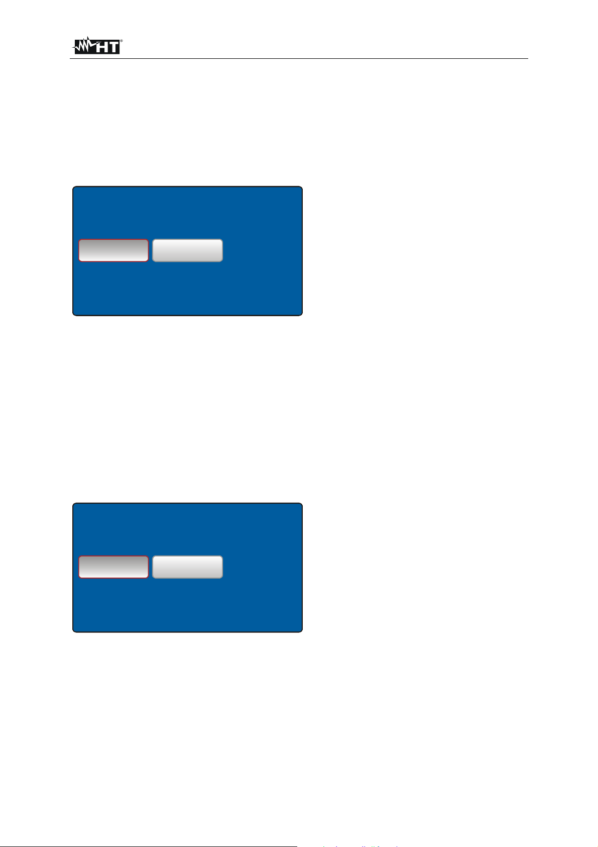
FULLTEST 3
6.5.5. NOMINAL VOLTAGE menu
This menu shall be used in order to select nominal mains voltage. The voltage may be either 230 or
240 V. It is used in LOOP and URES measurements.
In LOOP measurements it is used for calculation of prospective short-circuit current, see the “LOOP
IMPEDANCE / SHORT-CIRCUIT CURRENT (LOOP)” section.
In URES function (linear mode only) the nominal voltage is used for scaling of measured value, see the
“RESIDUAL VOLTAGE (URES)” section.
NOMINAL VOL.
230 V 240 V
Figure 59: NOMINAL VOL. menu
Select nominal voltage by pressing appropriate touch-screen key, the menu will turn to SETUP menu.
6.5.6. SAFETY menu
In order to set the status of safety input in DIELECTRIC function the SAFETY INPUT menu shall be
used. The safety input may be enabled or disabled.
Safety input disabled: DIELECTRIC test is active regardless of the safety input condition (safety switch
may be closed or opened or not connected at all).
Safety input enabled: DIELECTRIC test is active only if safety input condition is sufficient (safety switch
must be closed).
This safety input status does not influence to any other function except DIELECTRIC.
SAFETY INPUT
DISABLED ENABLED
Figure 60: SAFETY INPUT menu
Select the safety status by pressing appropriate touch-screen key, the menu will turn to SETUP menu.
EN - 69
Page 71

FULLTEST 3
6.6. SOUND menu
In order to turn the acoustic signals off/on SOUND menu shall be used.
SOUND
OFF
ON
Figure 61: SOUND menu
Select the SOUND status by pressing appropriate touch-screen key, screen will turn to SETUP menu.
EN - 70
Page 72
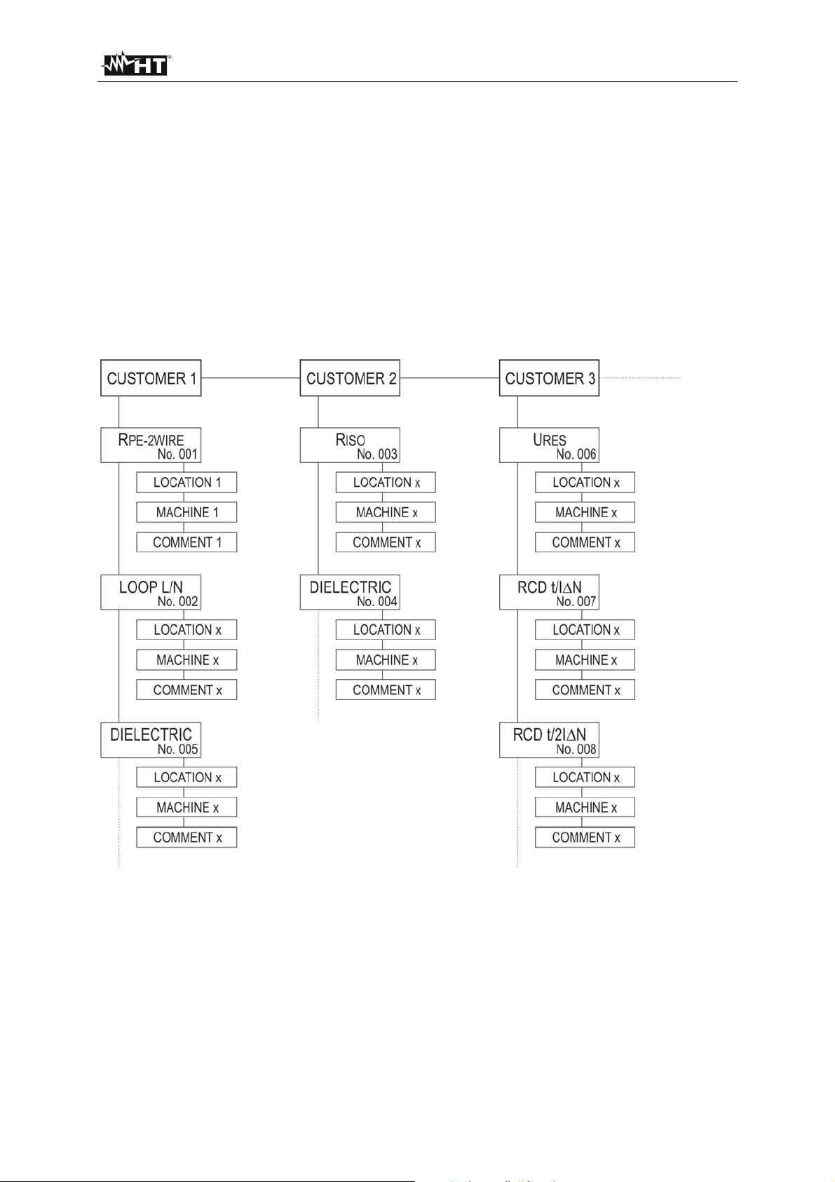
FULLTEST 3
7. MEMORY FEATURES
Any memory address consists of three levels i.e. LEVEL 1 (in production set to CUSTOMER), LEVEL 2
(in production set to LOCATION) and LEVEL 3 (in production set to MACHINE). The memory address
(at least LEVEL 1 i.e. CUSTOMER) should be entered after the first pressing the SAVE hard key.
Additionally comment can be added to each saved result. Once the address is entered, it will be offered
any time when save operation is activated. Serial number of saved result is added automatically
chronologically. Date, time and operator are attached automatically, that is why it is important to check
correct settings before carrying out the measurements.
7.1. MEMORY STRUCTURE
Measurement result, limit value and parameters are saved to selected memory address upon receiving
the SAVE command. The following structure of the memory address is offered:
Figure 62: Storage structure
LEVEL1 (e.g. CUSTOMER): Customer name (max. 12 characters)
LEVEL2 (e.g. LOCATION): Location of the customer (max. 12 characters)
LEVEL3 (e.g. MACHINE): Machine name (max. 12 characters)
NO.: Serial number of saved result added automatically chronological way
regardless of memory address.
COMMENT: Comment (max. 30 characters)
EN - 71
Page 73

FULLTEST 3
8. MEMORIZING EXAMPLE
In order to save measurement result to a particular storage address, follow the next steps:
1) Carry out the measurement.
2) Press the SAVE hard key, the following display will appear (example):
SAVE
CUSTOMER
COMPANY A
LOCATION
ROMA
MACHINE
PLASTIC INJECTION MACHINE
No
COMMENT
003
Figure 63: SAVE menu
3) Confirm the save operation by pressing the SAVE hard key again if offered address (CUSTOMER,
LOCATION and MACHINE) as well as COMMENT are OK. If offered address or comment is not
OK then modify them as follows:
- Press the level key you wish to modify for example CUSTOMER, the following modification
DEVICE SERVICED
display will appear (example):
Figure 64: SAVE - SELECT CUSTOMER menu
- Check the list of available customers by using the ▼ and ▲ touch-screen keys (if there are
more than 4 customers entered).
- Select wished customer by pressing the customer’s touch-screen key, e.g. CUSTOMER 4.
- Press the ENTER touch-screen key to confirm the selection and to exit the SAVE – SELECT
CUSTOMER menu, SAVE menu will be displayed again.
How to add a new customer:
- Press the ADD NEW touch-screen key, the following display will appear.
EN - 72
Page 74
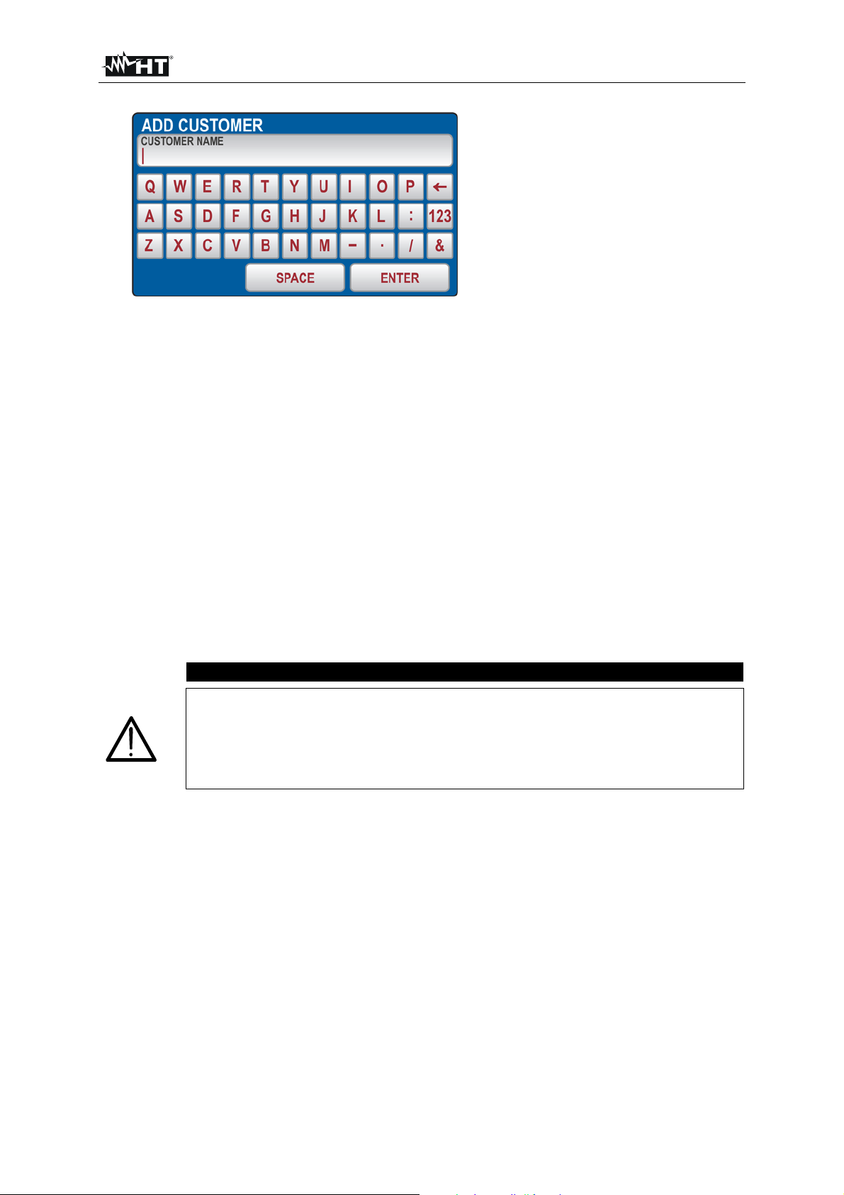
FULLTEST 3
Figure 65: ADD CUSTOMER menu
- Create new customer’s name. Use the 123 / ABC key to select figure or character selection
screen.
- Confirm entered name by pressing the ENTER touch-screen key, SAVE – SELECT
CUSTOMER screen will appear again and last entered operator will be selected.
Press the ENTER touch-screen key to confirm selected customer, SAVE menu will be offered
again.
Repeat the operation for the other two levels and for comment if needed following the same
procedure. In case of entering new LOCATION or MACHINE, previously selected name will be
offered.
Once all data (customer, location, machine and comment) are entered/selected press the SAVE
hard key again to confirm started save operation. A beep-beep sound will follow as a confirmation
save operation has successfully been accomplished. Measurement screen will be offered again.
CAUTION
LEVEL 1 (e.g. CUSTOMER) must obligatory be entered when saving test result
while LEVEL 2 (e.g. LOCATION), LEVEL 3 (e.g. MACHINE) and COMMENT are
not required.
Levels shall be selected/entered in order from the top (LEVEL 1) to the bottom
(COMMENT). Do not skip empty level.
EN - 73
Page 75
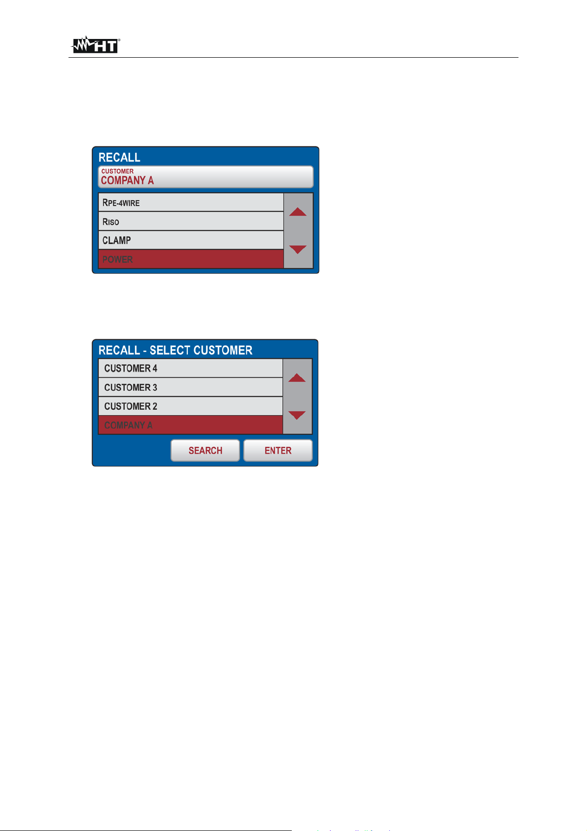
FULLTEST 3
9. RECALL RESULTS
In order to recall saved measurement result, follow the next steps:
1) Press the RCL hard key, the following screen will appear.
Figure 66: RECALL menu
2) Check offered customer and if needed, select another one by pressing the CUSTOMER touch-
screen key first. The following screen will appear.
Figure 67: RECALL - SELECT CUSTOMER menu
- Check the list of available customers by using the ▼ and ▲ touch-screen keys (if there are
more than 4 customers entered).
- Mark appropriate customer by pressing the customer touch-screen key, e.g. CUSTOMER 3.
- Confirm the selection by pressing the ENTER touch-screen key, screen will turn to RECALL
menu.
Note! If there is a list of many available customers use the SEARCH touch-screen key to select
appropriate one quickly.
3) Select wished measurement by using the ◄ and ► keys.
4) Press the RCL hard key again, saved result will be displayed as follows.
EN - 74
Page 76

FULLTEST 3
Figure 68: ILEAK function RECALL screen
5) Press the RCL hard key again in order to check next screens.
EN - 75
Page 77

FULLTEST 3
10. ENTRY OF DATA BY USING AN EXTERNAL KEYBOARD
The optional USB keyboard is a welcome accessory when inserting memory address construction
(customer, machine and location) as well as comment, in order to do the job quickly and simply.
Connect the USB keyboard to USB2 or USB3 connector, three sound signals will follow after plugging it,
as a confirmation of USB-device recognition. Now, the external keyboard is operational.
11. ENTRY OF DATA USING A BARCODE READER
The optional USB barcode reader is a welcome accessory when inserting memory address structure
(customer, machine and location) as well as comment, in order to do the job quickly and simply.
Connect the USB barcode reader to USB2 or USB3 connector, three sound signals follow after plugging
it, as a confirmation of USB device recognition.
12. FW UPDATE OF THE FULLTEST 3
The FW update can be done through USB drive, follow the next steps:
- Download new FW version for example B03.M04.V02 from PC to USB drive.
- Connect the USB drive to USB2 or USB3 connector of the FULLTEST 3, label DO YOU WISH TO
UPDATE TO VERSION B03.M04.V02? will appear.
- Confirm upload operation by pressing the YES touch-screen key.
- Wait until the display returns to initial screen then remove the USB drive, new FW is thus installed.
13. MAINTENANCE
When using the instrument in compliance with the instruction manual, no special maintenance is
required. However, should functional errors occur during normal operation, our after sales service will
repair your instrument without delay.
13.1. CLEANING
If the tester is needed to be cleaned after daily usage, it is advisable to use a wet cloth and a mild
household detergent.
Prior to cleaning, remove the machinery tester from all measurement circuits and from mains.
Never use acid-based detergents or dissolvent liquids for cleaning.
After cleaning it, do not use the instrument until it is completely dried up.
13.2. FUSE REPLACEMENT
If, due to overload or improper operation, a fuse blows, it is necessary to obey the following notes for
replacement:
WARNING
Prior to replacement of blown fuse, the Machinery-Tester FULLTEST 3 must be disconnected from all
measuring circuits and mains supply cord must be removed from mains supply socket.
• Use only fuses specified and rated in technical specifications.
• Use of unspecified fuses and in particular shortcircuiting fuse-holders is prohibited.
• Spare fuses can be obtained in electric supplies wholesale shops or in our factory service.
EN - 76
Page 78

FULLTEST 3
Fuse replacement (fuse F1, F2)
The two fuses are general ones for the tester and protect internal circuitry in POWER, RPE and
DIELECTRIC measurements.
In case mains switch pilot lamp (5) does not illuminate after connecting the Machinery-Tester
FULLTEST 3 to mains outlet and switching on the mains switch and neither the LC-Display (24) shows
any indication, it is very likely mains fuse F1 (4) or F2 (3) or both to be blown.
To replace the fuse proceed as follows:
1) Open the fuse holder F1 (4) and F2 (3) by using an appropriate screwdriver.
2) Remove the defective fuse and replace it with a new one (T16A/250V, 5×20 mm).
3) Replace the fuse holder.
Fuse replacement (fuse F3 for LOOP, RA and RCD functions)
F3 (FF 12.5 A / 500 V, 6.3 × 32 mm) has blown if:
• Text FUSE F3 appears on the display in LOOP, RA or RCD function.
To replace the fuse proceed as follows:
1) Unlock corresponding fuse holder (2) by using an appropriate screwdriver
2) Remove the defective fuse and replace it with a new one (FF 12.5 A / 500 V, 6.3 × 32 mm).
3) Lock the fuse holder again.
Fuse replacement (fuse F4 for RPE function)
Fuse F4 (F20A/500V 6.3 x 32 mm) has blown if message FUSE F4 appears on the display in RPE
function.
To replace the fuse proceed as follows:
1) Unlock corresponding fuse holder F4 (15) by using an appropriate screwdriver
2) Remove the defective fuse and replace it with a new one.
3) Replace the fuse holder.
☞ If any fuse blows several times (for example in case of operating
error) the instrument must be sent in to the service department in
order to be checked.
EN - 77
Page 79
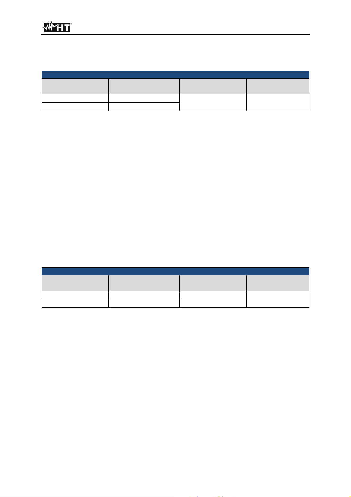
FULLTEST 3
14. TECHNICAL SPECIFICATIONS
14.1. MEASUREMENT FUNCTIONS
CONTINUITY OF PROTECTIVE CONDUCTOR (RPE-2WIRE, 0.2A)
Display range
()
0.00 19.99
20.0 200.0
Resolution
(M)
0.01
0.1
Accuracy Overvoltage protection
± (3% rdg. + 3 dgt) CAT III 300 V
Standard test leads: 2 × 2 m, 2.5 mm2
Open-circuit test voltage: Approx. 4.5 V AC (floating)
Short-circuit test current: < 0.6 A (standard test leads)
Test current: > 0.2 A (standard test leads and external resistance < 20 )
Display range of test current: 10 255 mA
Accuracy of displayed test current: ± (3% rdg. + 2 dgt)
Limit value: Adjustable 0.01 19.99, 20.0 200.0
Measurement principle: Two-wire connection
Test lead calibration: Up to 5.00
Protection against ext. voltage: Fuse F4 (T20A/500V, 6.3×32 mm), blown fuse automatically
detected in R
PE measurement
Detection of external voltage Yes
- UEXT lim = 3 V AC (between two RPE or between two
SENSE terminals before measurement)
-
UEXT lim = 10 V AC (between two RPE or between two
SENSE terminals during measurement)
-
UEXT lim = 30 V AC approx. (between any RPE/SENSE
terminal and GND before/during measurement)
CONTINUITY OF PROTECTIVE CONDUCTOR (RPE-2WIRE, 25A)
Display range
()
0.000 1.999
2.00 20.00
Resolution
(M)
0.001
0.01
Accuracy Overvoltage protection
± (3% rdg. + 3 dgt) CAT III 300 V
Standard test leads: 2 × 2 m, 2.5 mm2
Open-circuit test voltage: Approx. 4.5 V AC (floating)
Short-circuit test current: < 30 A (standard test leads)
Test current (25A range): > 25 A (standard test leads and external resistance < 0.1 )
> 10 A (standard test leads and external resistance < 0.5 )
Display range of test current: 0.2 30.0 A
Accuracy of displayed test current: ± (3% rdg. + 1 dgt)
Limit value: Adjustable 0.01 20.00 or
Calculation through loop impedance or
Calculation through wire length
Measurement principle: Two-wire connection
Test lead calibration: Up to 5.00
Protection against ext. voltage between
current terminals (RPE): Fuse F4 (T20A/500V, 6.3×32 mm), blown fuse automatically
detected
Detection of external voltage Yes, see the limit values explanation above (PROTECTIVE
CONDUCTOR (R
PE-2WIRE, 0.2A))
EN - 78
Page 80

FULLTEST 3
Continuity of protective conductor (RPE-4WIRE, 25A)
Display range
()
0.000 1.999
2.00 20.00
Standard test leads: 2 × 2 m, 2.5 mm
Resolution
(M)
0.001
0.01
Accuracy Overvoltage protection
± (3% rdg. + 3 dgt) CAT III 300 V
2
Open-circuit test voltage: Approx. 4.5 V AC (floating)
Short-circuit test current: < 30 A (standard test leads)
Test current (25A range): > 25 A (standard test leads and external resistance < 0.1 )
> 10 A (standard test leads and external resistance < 0.5 )
Display range of test current: 0.2 30.0 A
Accuracy of displayed test current: ± (3% rdg. + 1 dgt)
Limit value: Adjustable 0.01 20.00 or
Calculation through loop impedance or
Calculation through wire length
Measurement principle: Four-wire connection
Protection against ext. voltage: Fuse F4 (T20A/500V, 6.3×32 mm), blown fuse
automatically detected
Detection of external voltage Yes, see the limit values explanation above (PROTECTIVE
CONDUCTOR (R
PE-2WIRE, 0.2A))
EN - 79
Page 81
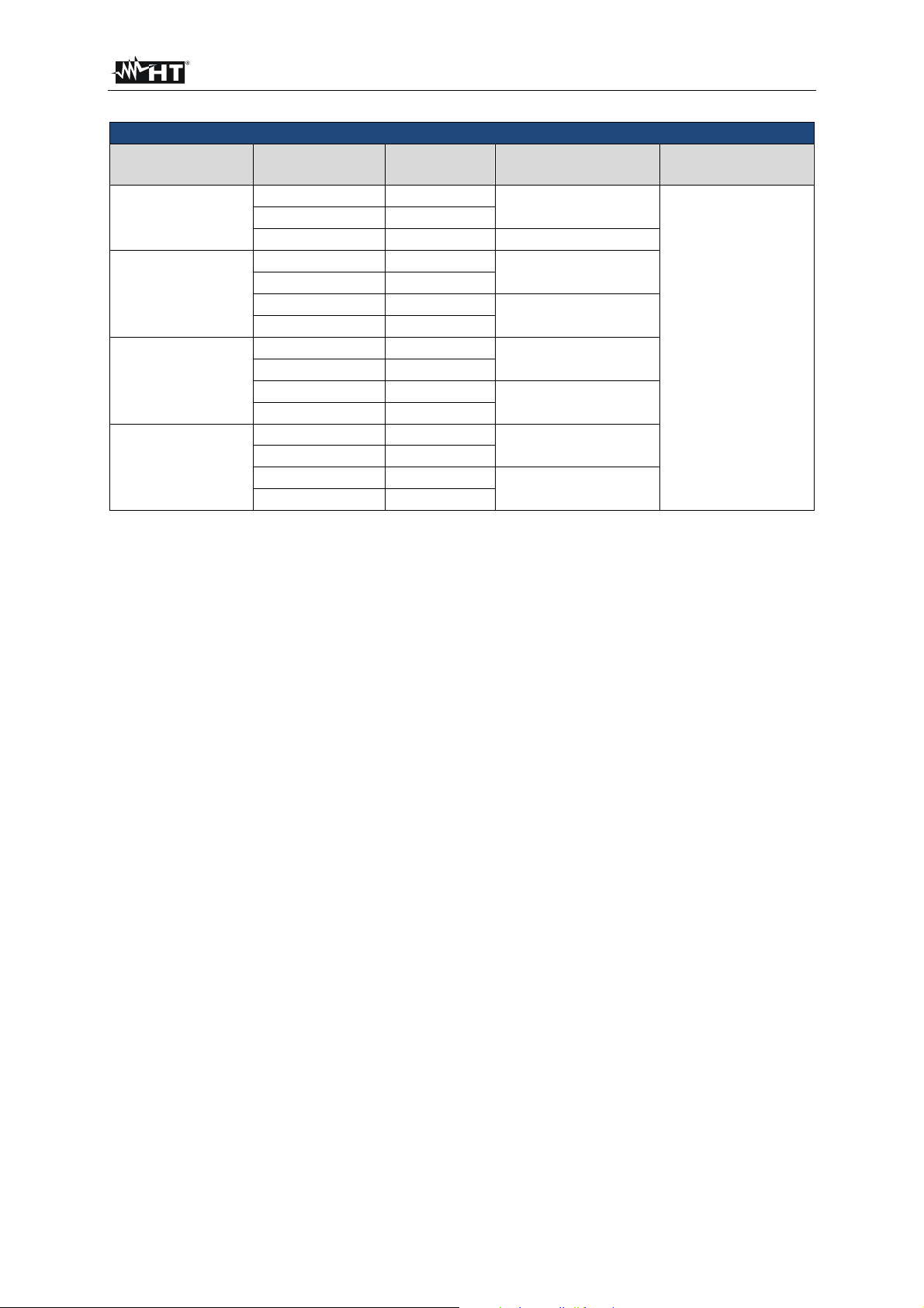
FULLTEST 3
Insulation resistance (M)
DC test voltage
(V)
100
250
500
1000
Display range
(M)
0.00 9.99
10.0 20.0
20.0 99.9
0.00 9.99
10.0 20.0
20.0 99.9
100 250
0.00 9.99
10.0 20.0
20.0 99.9
100 500
0.00 9.99
10.0 20.0
20.0 99.9
100 1000
Resolution
(M)
0.01
0.1
0.1
0.01
0.1
0.1
1
0.01
0.1
0.1
1
0.01
0.1
0.1
1
Accuracy Overvoltage
± (3% rdg. + 3 dgt)
± 5% rdg.
± (3% rdg. + 3 dgt)
± 5% rdg.
CAT III 300 V
± (3% rdg. + 3 dgt)
± 5% rdg.
± (3% rdg. + 3 dgt)
± 5% rdg.
protection
Test voltage tolerance: (-0% +25%) of UN
Test current: > 1 mA (up to UN/1mA)
Short-circuit current: < 15 mA
Discharge: Internal resistance of 2 M (after finishing the measurement)
Detection of external voltage Yes
- UEXT lim = 10 V AC (between RISO+ and RISO- terminals
before measurement)
-
UEXT lim = 50 V AC (between RISO+ and RISO- terminals
during measurement)
- UEXT lim = 50 V AC approx. (between any RISO terminal
and GND)
- UEXT lim = -10 V DC (between RISO+ and RISO- terminals
during measurement)
EN - 80
Page 82
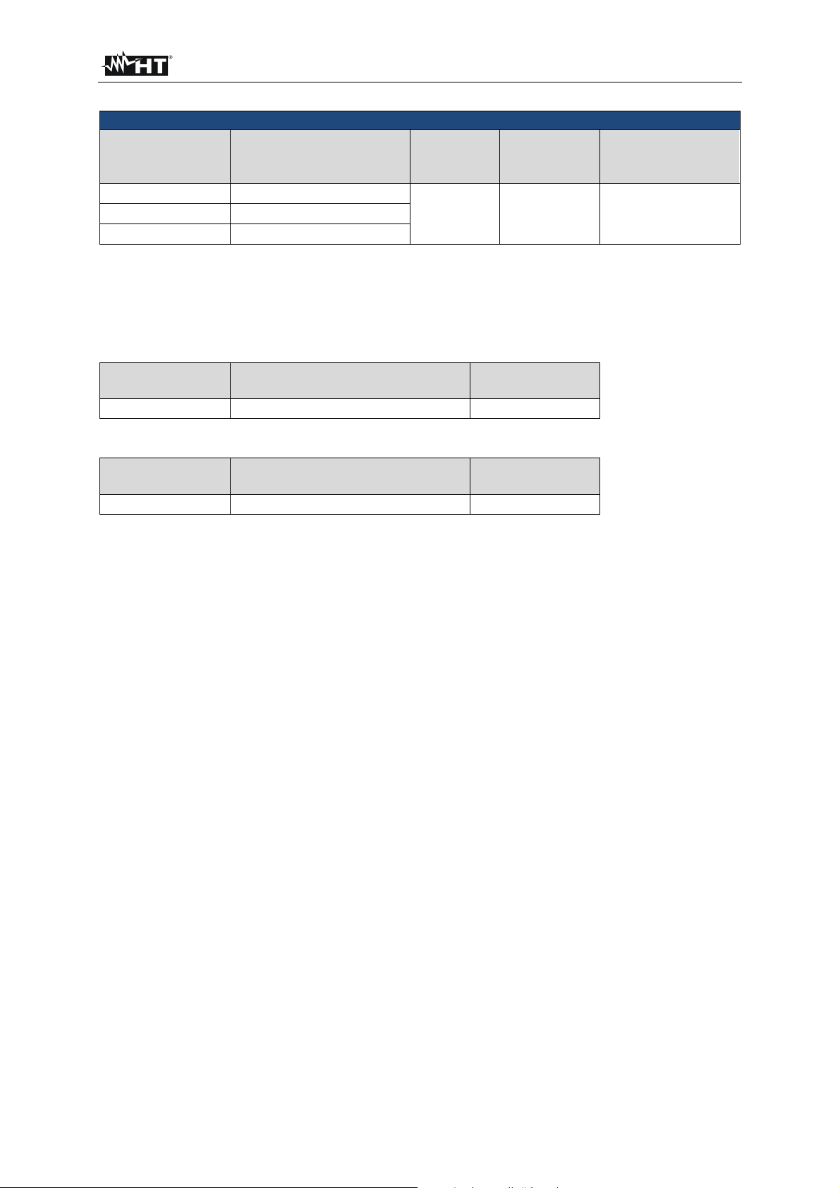
FULLTEST 3
Dielectric withstanding test (DIELECTRIC)
Nominal test
voltage UN
(V)
250 800 COM & 0.250.80 kV
810 2500 COM & 0.812.50 kV
2510 5100 COM & 2.515.10 kV
Output
Resolution
(V)
10 ± 3% U
output voltage
Accuracy of
N CAT III 300 V
Overvoltage
protection
Nominal test voltage UN: Adjustable 250 5100 V, 50/60 Hz (floating) in steps of 10 V
Distortion of test voltage: Crest factor = 1.414 ± 5%
Measurement modes: MANUAL, RAMP (timer) or BURN
Output power: 500 VA at 5100 V
Leakage current IAPP:
Display range
(mA)
0 200
Resolution
(mA)
1 ± (3% rdg + 2 mA)
Accuracy
Leakage current IREAL:
Display range
(mA)
0 110
Resolution
(mA)
1 ± (3% rdg + 4 mA)
Accuracy
Nominal breaking current (IAPP or IREAL): Adjustable 1 110 mA in steps of 1 mA
Short-circuit current: > 200 mA
Breaking time: < 30 ms
Note!
Always connect COM terminal to GND if measured OUT is grounded, otherwise possible capacitive
leakage current may flow to ground which may disturb the measurement!
EN - 81
Page 83
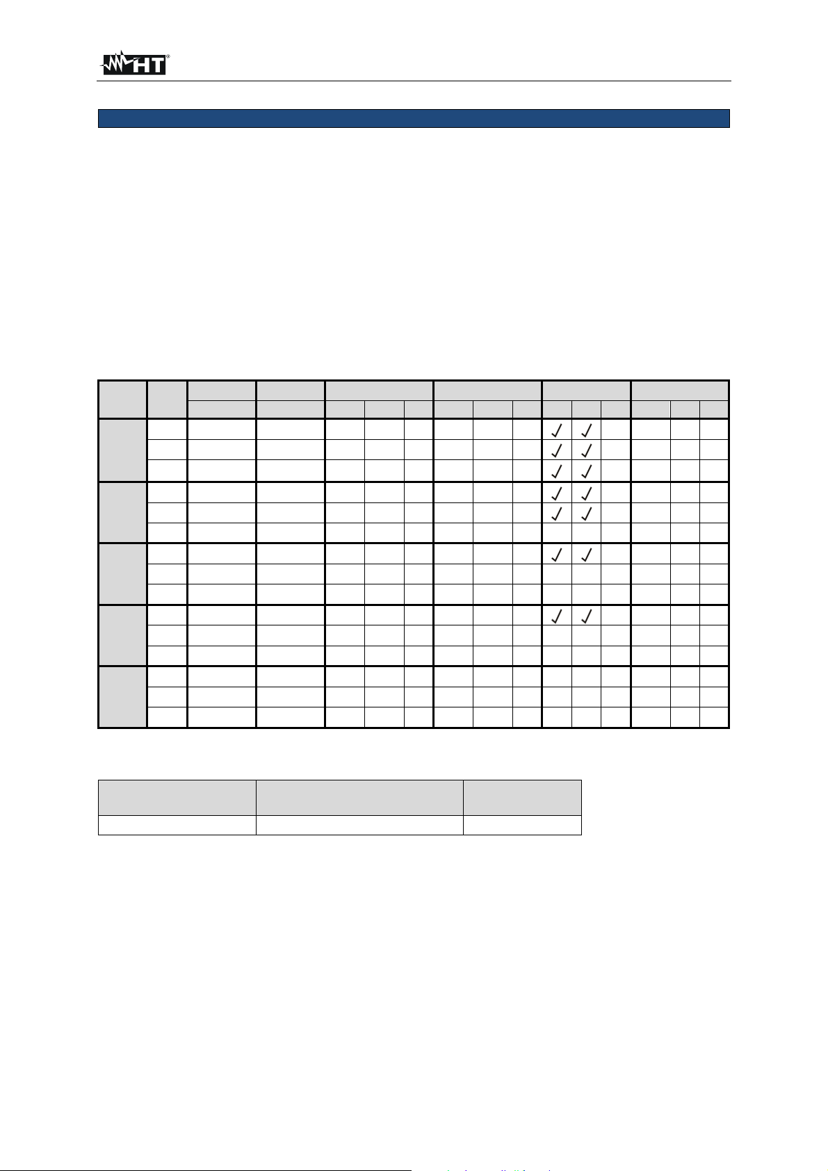
FULLTEST 3
RCD test (RCD)
RCD types / characteristics: AC, A or B / General, Selective or Delayed
Measurement modes: x1/2IN, x1IN, x2IN, xKIN (K = 4 B type, K=5 AC, A type),
I (RAMP), AUTO (sequence: x1/2, x1, xK)
Nominal currents: 10, 30, 100, 300, 500, 650 or 1000 mA
Accuracy of test currents (10 mA): - 10% / + 0% (IN/2)
+ 10% / - 0% (IN, 2IN, KIN)
Accuracy of test currents (301000 mA): - 5% / + 0% (IN/2)
+ 5% / - 0% (IN, 2IN, KIN)
Input voltage range / frequency: 100 265 V / (50 / 60 Hz) ± 0.5 Hz
Contact voltage limits: 25 V or 50 V selectable
Test current polarity: POSITIVE or NEGATIVE selectable
Test duration (ms) – TT/TN system:
IN
(mA)
10
30
100
300
500
650
1000
AC 1000 1000 200 250 50 150
A 1000 1000 200 250 50 150
B 1000 1000 200 250
AC 1000 1000 200 250 50 150
A 1000 1000 200 250 50 150
B 1000 1000 320
AC 1000 1000 200 250 50 150
A 1000 1000 200 250 320
B 1000 1000 320
AC 1000 1000 200 250 50 150
A 1000 1000 200 250 320
B
AC 1000 1000 200 250 320
A 1000 1000
B
×1/2 ×1 ×2 ×K AUTO RAMP
G, S, D G, S, D G S D G S D G S D G S D
320
320
320
320
320
320
320
Resolution: 1ms, Accuracy: ± (3% rdg + 2 ms)
Mains voltage UL/N, UL/PE:
Display range
(V)
100 265
Resolution
(V)
Accuracy
1 ± (3% rdg.)
Input resistance (UL/N, UL/PE): 450 k
Ramp test: YES, current range 10 110% of IN in steps of 5% of IN
AUTO TEST: YES, test steps are as follows:
- t/IN/2 (pos. polarity)
- t/IN/2 (neg. polarity)
- t/IN (pos. polarity)
N (neg. polarity)
- t/I
- t/5I
N, (pos. polarity)
- t/5IN (neg. polarity)
EN - 82
Page 84

FULLTEST 3
LOOP impedance / Short-circuit current (LOOP)
Display range
()
*0.000 2.000
0.00 9.99
10.0 99.9
100 200
Resolution
(M)
0.001
0.01
0.1
1
Accuracy Overvoltage protection
± (3% rdg. + 3 dgt) CAT III 300 V
* With optional accessory IMP57 only!
Input voltage range LOOP L/PE or L/N: 100 265 V, 50/60 Hz
Input voltage range LOOP L/L: 100 460 V, 50/60 Hz
Nominal mains voltage: 230 or 240 V
Loading resistance: 10 for 20 ms (range 0.00 30.0 ) and
180 for 20 ms (range 30.0 200.0 )
ISC calculation: Depends on selected limit mode
Short-circuit current ISC:
Display range
(A)
0.05 0.99
1.0 99.9
100 999
1.00k 46.00k
Resolution
(A)
0.01
0.1
1
10
Accuracy
Depends on U
and Z accuracy
L/PE
Mains voltage UL/N, UL/PE:
Display range
(V)
100 265
Resolution
(V)
1 ± (3% rdg.)
Accuracy
Input resistance (UL/N, UL/PE): 450 k
Mains voltage UL/L:
Display range
(V)
100 460
Resolution
(V)
1 ± (3% rdg.)
Accuracy
Input resistance (UL/N, UL/PE): 450 k
EN - 83
Page 85

FULLTEST 3
Global earth resistance without tripping RCD (RA)
IN
(mA)
10
30
100
300
500
650
1000
Display range RA
()
0 2000
0.0 99.9
100 2000
0.0 99.9
100 1000
0.0 99.9
100 300
0.0 99.9
100 200
0.0 99.9
100 150
0.0 100.0
Resolution
()
1
0.1
1
0.1
1
0.1
1
0.1
1
0.1
1
0.1
± (3% rdg. + 1 ), 15 2000 *
± (3% rdg. + 1 ), 10 2000 *
± (3% rdg. + 3 dgt)*
* The accuracy may be affected unstabile mains voltage!
Test current: IN /2
Input voltage range: 100
265 V, 50/60 Hz
Nominal mains voltage : 230 or 240 V
Mains voltage U
Display range
100 265
(V)
L/PE:
Resolution
(V)
1 ± (3% rdg.)
Input resistance (UL/PE): 450 k
Contact voltage UC at IN:
Display range
(V)
0 100 (UC LIM = 50 V)
0 50 (UC LIM = 25 V)
Resolution
(V)
1 ± (3% rdg. + 3 V)
Accuracy Overvoltage
protection
CAT III 300 V
Accuracy
Accuracy
EN - 84
Page 86
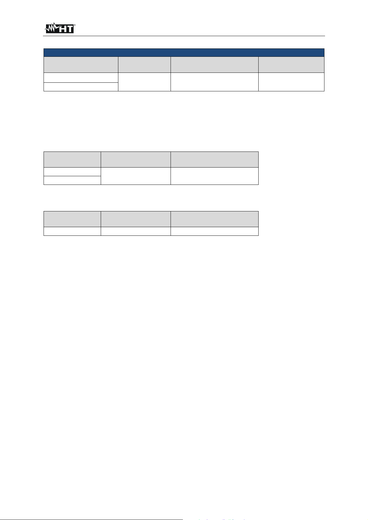
FULLTEST 3
TRMS Residual voltage (URES)
Display range
10 460
10 650
Resolution
(V)
1 ± (3% rdg. + 3 V) CAT III 300 V
Accuracy
(general)
Overvoltage protection
Input voltage (UTRIG): 0 460 VAC
Nominal mains voltage: 230 or 240 V
Measurement method: 4-wire connection (INTERNAL measurement, 1 s or 5 s)
2-wire connection (PLUG measurement, 1 s)
Residual voltage limit value: 60 V RMS
Input voltage URES:
Display range
(V)
10 460 VAC
10 650 VDC
Resolution
(V)
1 ± (2% rdg. + 2 V)
Accuracy
Input resistance (URES): 100 M
Input voltage UTRIG:
Display range
(V)
10 265 VAC
Resolution
(V)
1 ± (2% rdg. + 2 V)
Accuracy
Input resistance (UTRIG): 450 k
EN - 85
Page 87

FULLTEST 3
TRMS Load Current (POWER)
Display range
A
0.00 0.99
1.0 20.0
Resolution
A
0.01
0.1
Accuracy Overvoltage protection
± (3% rdg. + 3 dgt) CAT II 300 V
Frequency range: 15 723 Hz
Over-range limit: Yes, the measurement will be automatically interrupted 10 s
after exceeding 16 A
Pre-Test Grounding of PE terminal on wall schuko socket
TRMS Mains Voltage (POWER)
Display range
V
195 253
Resolution
V
1 ± (2% rdg. + 2 dgt) CAT II 300 V
Accuracy Overvoltage protection
Frequency range: 15 723 Hz
Apparent Power / Active Power (POWER)
Display range
VA/W
0.0 99.9
100 999
1.00 5.06 k
Resolution
VA/W
0.1 ± (5% rdg. + 10 dgt)
1
10
Accuracy Overvoltage protection
± (5% rdg. + 3 dgt)
CAT II 300 V
Limit value PAPP: Adjustable 6 999 VA, 1.00 kVA 5.06 kVA
Power factor (POWER)
Display range Resolution Accuracy Overvoltage protection
0.00 1.00
0.01 Respect the accuracy of P
APP and PACT CAT II 300 V
TRMS Leakage Current IPE (POWER)
Display range Resolution Accuracy Overvoltage protection
0.25 19.99 mA
20.0 49.9 mA
0.05 0.99 A
1.0 10.0 A
0.01 mA
0.1 mA
0.01 A
0.1 A
± (3% rdg. + 3 dgt) CAT II 300 V
Load current influence: ± 0.01 mA / A
Limit value: Adjustable 0.25 mA 10.00 A, standard limit value 3.50 mA
Frequency range: 40 Hz 100 kHz (characteristics according to
DIN EN 61010-1 Annex A, fig. A.1 and VDE 0411 Part 1)
Measurement method: Differential
Mains cord polarity exchange Internally by using the L POS key
UUT mains on switch test: Yes, the test done by measuring L current, limit value 25 mA
Over-range limit (I
PE): Yes, the measurement will be automatically interrupted 10 s
after exceeding 10 A
Over-range limit (IL): Yes, the measurement will be automatically interrupted 10 s
after exceeding 18 A
EN - 86
Page 88

FULLTEST 3
PHASE SEQUENCE (PHASESEQ)
Display range
UL1/2, UL2/3, UL3/1
(V)
360 460
Resolution
(V)
1 ± (2% rdg. + 2 dgt) CAT III 300 V
Accuracy Overvoltage protection
Display of test result: 1.2.3 (right) or 2.1.3 (left) or 1.1.X (not defined)
TRMS Clamp Current (ICLAMP)
Range Display range Resolution
1000 mA
100.0 A
1000 A
0.0 99.9 mA
100 1000 mA
0.00 9.99 A
10.0 100.0 A
0.0 99.9 A
100 1000 A
0.1 mA
1 mA
0.01 A
0.1 A
0.1 A
1 A
Accuracy
(w/o clamp error)
± (3% rdg. + 3 dgt)
Overvoltage protection
One measurement
terminal grounded
Input voltage range: 0 1 V AC
Input resistance: 1 M
Frequency range: 40 Hz 100 kHz (characteristics according to
DIN EN 61010-1 Annex A, fig. A.1 and VDE 0411 Part 1)
Clamp type: AC, output voltage 1 V / measuring range, type
HT96U (measuring ranges 1 A, 100 A, 1000 A)
LIM value (1000 mA range): Adjustable 0.1 ... 99.9 mA, 100 ... 1000 mA
LIM value (100.0 A range): Adjustable 0.1 ... 100.0 A
LIM value (1000 A range): Adjustable 1 ... 1000 A
EN - 87
Page 89
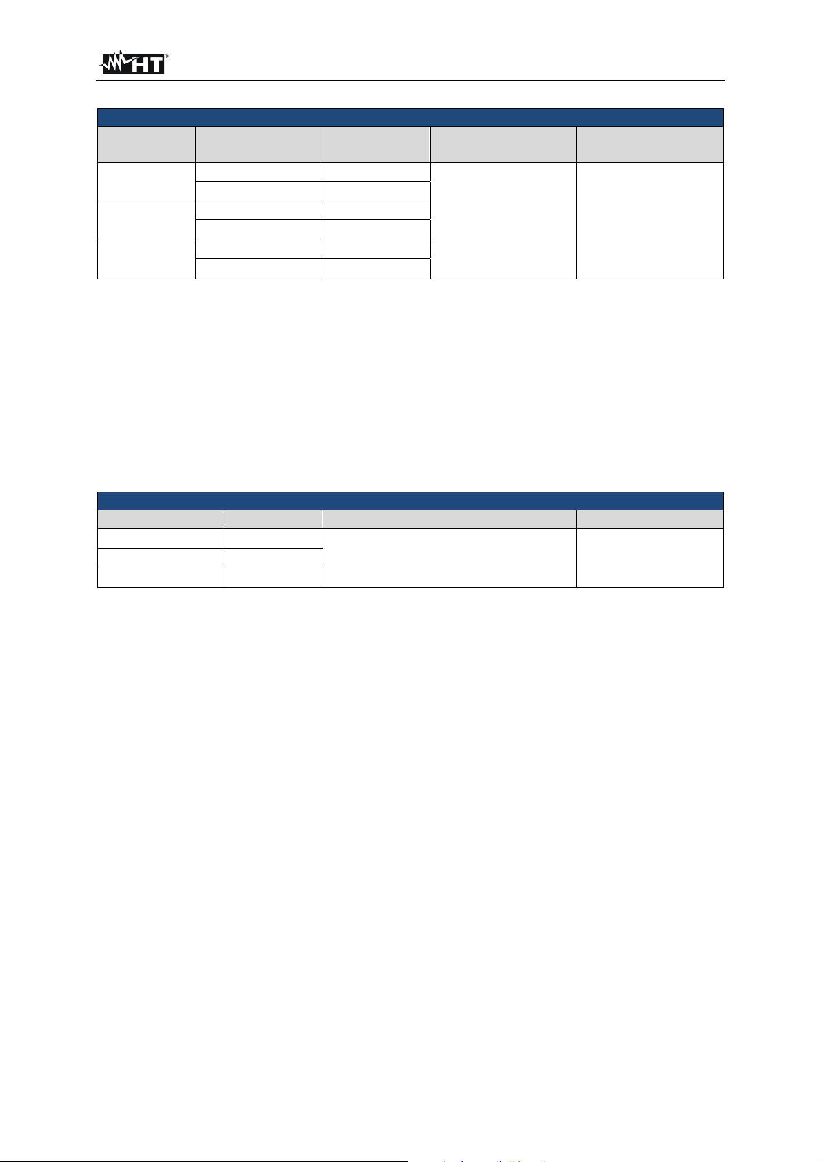
FULLTEST 3
TRMS Leakage current using current clamp (ILEAK)
Range Display range Resolution
1000 mA
100.0 A
1000 A
0.0 99.9 mA
100 1000 mA
0.00 9.99 A
10.0 100.0 A
0.0 99.9 A
100 1000 A
0.1 mA
1 mA
0.01 A
0.1 A
0.1 A
1 A
Accuracy
(w/o clamp error)
± (3% rdg. + 3 dgt)
Overvoltage protection
One measurement
terminal grounded
Input voltage range: 0 1 V AC
Input resistance: 1 M
Frequency range: 40 Hz 100 kHz (characteristics according to
DIN EN 61010-1 Annex A, fig. A.1 and VDE 0411 Part 1)
Clamp type: AC, output voltage 1 V / measuring range, type
HT96U (measuring ranges 1 A, 100 A, 1000 A)
LIM value (1000 mA range): Adjustable 0.1 ... 99.9 mA, 100 ... 1000 mA
LIM value (100.0 A range): Adjustable 0.1 ... 100.0 A
LIM value (1000 A range): Adjustable 1 ... 1000 A
TRMS Leakage Current on test socket (ILEAK)
Display range Resolution Accuracy Overvoltage protection
0.25 49.99 mA
0.05 0.99 A
1.0 10.0 A
0.01 mA
0.01 A
0.1 A
± (3% rdg. + 3 dgt)* CAT II 300 V
* Clamp error not included
Load current influence ± 0.01 mA / A
Limit value Adjustable 0.25 19.99 mA, 20.0 49.9 mA, 0.05 0.99 A,
1.0 10.0 A
Frequency range 40 Hz 100 kHz (characteristics according to
DIN EN 61010-1 Annex A, fig. A.1 and VDE 0411 Part 1)
Measurement method Differential
Mains cord polarity exchange Internally by using the L POS key
UUT mains ON switch test Yes, the test done by measuring L current, limit value 25 mA
Over-range limit (I
PE) Yes, the measurement will be automatically interrupted 10 s
after exceeding 10 A
Over-range limit (I
L) Yes, the measurement will be automatically interrupted 10 s
after exceeding 18 A
Pre-Tests - Grounding of PE terminal on wall schuko socket
- Status of ON/OFF mains switch on UUT (measurement of
power consumption on schuko test socket, limit value 6 VA)
EN - 88
Page 90

FULLTEST 3
14.2. GENERAL SPECIFICATION
POWER SUPPLY
Mains voltage: 207 253 V / 50/60 Hz ± 5%
Current consumption: 16 Amax
MECHANICAL SPECIFICATIONS
Dimensions (L x W x H): 400 x 300 x 170 mm
Weight: 15 kg
MEMORY AND INPUT/OUTPUT INTERFACES
Internal memory: 999 locations (three-level memory structure)
PC interface: USB 2.0 device, connector type “B”
USB keyboard, USB printer, pen drive,
USB barcode reader: 2 x USB 2.0 host, connector type “A”
Pen drive requirements: FAT12, FAT16 or FAT32 with a sector size of 512 Byte
Warning lamp: For dielectric test
Keyboard for remote controls
START/STOP/SAVE keys: Yes
Bluetooth interface connection
to mobile devices: Yes
ENVIRONMENTAL CONDITIONS
Reference temperature: 23°C ± 5°C
Working temperature: 0° 40°C
Reference humidity: < 60% RH w/o condensation
Working humidity: < 80% RH w/o condensation
Storage temperature: -10 60°C
Storage humidity: < 80% RH w/o condensation
REFERENCE GUIDELINES
Safety tests machines/
switchboards/devices: IEC/EN60204-1:2006; IEC/EN61439-1; IEC/EN60335-1
Literature: IEC/EN61187
Instrument: IEC/EN61557-1-2-3-4-6-13-14
GENERAL CHARACTERISTICS
Display: 4.3 inch colour TFT LCD with touch screen,
Limit value setting: See each function separately
Warning in case of exceeded
Limit values: Optic and acoustic warning in case of exceeded value
Instrument safety: IEC/EN61010-1
Insulation: Protection class I (protection conductor)
Pollution degree: 2
Measurement category: CAT II 300V (Power), CAT III 300V (other tests)
Altitude above sea level: 2000 m
Mechanical protection: IP40
14.3. ACCESSORIES
Please see enclosed packing list.
EN - 89
Page 91

FULLTEST 3
15. SERVICE
15.1. WARRANTY CONDITIONS
This instrument is guaranteed against material or production defects, in accordance with our general
sales conditions. During the warranty period the manufacturer reserves the right to decide either to
repair or replace the product.
Should you need for any reason to return back the instrument for repair or replacement take prior
agreements with the local distributor from whom you bought it. Do not forget to enclose a report
describing the reasons for returning (detected fault). Use only original packaging. Any damage occurred
in transit due to non original packaging will be charged anyhow to the customer.
The manufacturer will not be responsible for any damage to persons or things.
Accessories (not covered by warranty).
The warranty does not apply to:
Repairs made necessary by improper use (including adaptation to particular applications not
foreseen in the instructions manual) or improper combination with incompatible accessories or
equipment.
Repairs made necessary by improper shipping material causing damages in transit.
Repairs made necessary by previous attempts for repair carried out by non skilled or unauthorized
personnel.
Instruments for whatever reason modified by the customer himself without explicit authorization of
our Technical Dept.
The contents of this manual may not be reproduced in any form whatsoever without the
manufacturer’s authorization.
Our products are patented and our logotypes registered. We reserve the right to modify
specifications and prices in view of technological improvements or developments which might
be necessary.
15.2. AFTER-SALE SERVICE
Shouldn’t the instrument work properly, before contacting your distributor make sure that batteries are
correctly installed and working, check the test leads and replace them if necessary. Make sure that your
operating procedure corresponds to the one described in this manual.
Should you need for any reason to return back the instrument for repair or replacement take prior
agreements with the local distributor from whom you bought it. Do not forget to enclose a report
describing the reasons for returning (detected fault). Use only original packaging. Any damage occurred
in transit due to non original packaging will be charged anyhow to the customer.
The manufacturer will not be responsible for any damage to persons or things.
Subject to technical changes without notice!
EN - 90
Page 92

Via della Boaria 40
48018 – Faenza (RA)- Italy
Tel: +39-0546-621002 (4 linee r.a.)
Fax: +39-0546-621144
Email: ht@htitalia.it
http://www.ht-instruments.com
 Loading...