

Page 1
User manual
EQUITEST 5071
Copyright HT ITALIA 2013 Versione EN 1.00 - 15/01/2013
Page 2

Page 3
EQUITEST 5071
Table of contents
1. PRECAUTIONS AND SAFETY MEASURES .................................................................. 2
1.1. Preliminary instructions ......................................................................................................... 2
1.2. During use ............................................................................................................................. 3
1.3. After use ................................................................................................................................ 3
Definition of measurement (overvoltage) category ......................................................................... 3
2. GENERAL DESCRIPTION .............................................................................................. 4
3. PREPARATION FOR USE .............................................................................................. 4
3.1. Initial checks .......................................................................................................................... 4
3.2. Instrument power supply ....................................................................................................... 4
3.3. Calibration ............................................................................................................................. 4
3.4. Storage .................................................................................................................................. 4
4. INSTRUMENT DESCRIPTION ........................................................................................ 5
4.1. Front panel ............................................................................................................................ 5
4.2. Input and output leads ........................................................................................................... 5
4.3. Description of function keys .................................................................................................. 6
4.4. Display description ................................................................................................................ 6
4.5. Initial screen .......................................................................................................................... 6
4.6. Backlight ................................................................................................................................ 7
5. INITIAL SETTINGS ......................................................................................................... 7
5.1. Adjusting display contrast ...................................................................................................... 7
5.2. Adjusting date and time ......................................................................................................... 8
5.3. Language setting ................................................................................................................... 8
6. OPERATING INSTRUCTIONS ........................................................................................ 9
6.1. LOW: Continuity of protective conductors with 200mA....................................................... 9
6.1.1.Calibration of measuring cables .................................................................................................. 10
6.1.2.Measuring.................................................................................................................................... 11
6.1.2.1. Anomalous situations in "AUTO", "RT+", "RT-" mode........................................................................... 13
6.2. LOW10A: Continuity of protective conductors with 10A ................................................... 14
6.2.1.Measuring.................................................................................................................................... 14
6.2.2.Anomalous situations .................................................................................................................. 16
6.3. LOW10AE204: Continuity 10A in compliance with IEC/EN60204-1:2006 ........................ 17
6.3.1.Measuring.................................................................................................................................... 18
6.3.2.Anomalous situations .................................................................................................................. 20
6.4. LOOP/Ra
6.4.1.High-resolution impedance measurement (0.1 m) ................................................................... 22
6.4.2."P-N" mode: measurement procedure and results ..................................................................... 22
6.4.3."P-P" mode: measurement procedure and results...................................................................... 24
6.4.4."P-PE" mode: measurement procedure and results ................................................................... 25
6.4.5."RA" mode: measurement procedure and results ................................................................... 27
6.4.6." " mode: measurement procedure and results ....................................................................... 29
: Loop impedance, overall earth resistance and phase sequence .................. 21
6.4.6.1. Anomalous situations in "P-P", "P-N", "P-PE","RA", " " mode ...................................................... 30
7. OPERATIONS WITH THE MEMORY ............................................................................ 34
7.1. Storage of measurement results ......................................................................................... 34
7.2. Recalling and deleting data from the memory ..................................................................... 34
8. CONNECTING THE INSTRUMENT TO THE PC .......................................................... 35
9. MAINTENANCE ............................................................................................................ 36
9.1. General information ............................................................................................................. 36
9.2. Battery replacement ............................................................................................................ 36
9.3. Cleaning the instrument ...................................................................................................... 36
9.4. End of life ............................................................................................................................ 36
10. TECHNICAL SPECIFICATIONS ............................................................................. 37
10.1. Reference standards ........................................................................................................... 38
10.2. General characteristics ........................................................................................................ 38
10.3. Environmental conditions .................................................................................................... 38
10.4. Accessories ......................................................................................................................... 38
11. SERVICE ................................................................................................................ 39
11.1. Warranty conditions ............................................................................................................. 39
11.2. Service ................................................................................................................................ 39
EN - 1
Page 4
EQUITEST 5071
1. PRECAUTIONS AND SAFETY MEASURES
The instrument has been designed in compliance with Standards IEC/EN61557 and
IEC/EN 61010-1 relevant to electronic measuring instruments.
For your safety and in order to prevent damaging the instrument, please
carefully follow the procedures described in this manual and read all notes
preceded by the symbol with the utmost attention.
Before and after carrying out the measurements, carefully observe the following
instructions:
Do not carry out any voltage or current measurement in humid environments
Do not carry out any measurements in case gas, explosive materials or flammables are
present, or in dusty environments
Avoid contact with the circuit being measured if no measurements are being carried out
Avoid contact with exposed metal parts, unused measuring probes, circuits, etc.
Do not carry out any measurement in case you find anomalies in the instrument such
as deformation, substance leaks, absence of display on the screen, etc.
Pay special attention when measuring voltages higher than 25V in special
environments (such as construction sites, swimming pools, etc.) and 50V in normal
environments, since a risk of electrical shock exists.
Only use original accessories.
In this manual, and on the instrument, the following symbols are used:
CAUTION: observe the instructions given in this manual; improper use could
damage the instrument, its components and create dangerous situations for the
operator.
CAUTION
Presence of dangerous voltage ( 30V): electrical shock hazard
Double-insulated meter
AC voltage or current
Connection to earth
1.1. PRELIMINARY INSTRUCTIONS
This instrument has been designed for use in environments of pollution degree 2.
The instrument may be used for measuring and verifying the safety of electrical
systems of overvoltage category CAT III 300V (to earth) or CAT II 350V (to earth).
We recommend following the normal safety rules devised to protect the user against
dangerous currents and the instrument against incorrect use.
Only the accessories provided together with the instrument will guarantee safety
standards. If necessary, replace them with identical models.
Do not test circuits exceeding the specified current and voltage limits. Do not perform
any test under environmental conditions exceeding the limits indicated in § 10.3.
Check that the batteries are correctly inserted.
Before connecting the test leads to the circuit to be tested, make sure that the switch is
correctly set.
EN - 2
Page 5
EQUITEST 5071
1.2. DURING USE
Please carefully read the following recommendations and instructions:
CAUTION
Failure to comply with the caution notes and/or instructions may damage
the instrument and/or its components or be a source of danger for the
operator.
Before activating the rotary switch, disconnect the test leads from the circuit under test.
When the instrument is connected to the circuit under test, never touch any terminal,
even if unused.
Avoid measuring resistance if external voltages are present. Even if the instrument is
protected, excessive voltage could cause damage.
1.3. AFTER USE
When measurements are complete, turn off the instrument by pressing and holding the
ON/OFF key for some seconds.
If the instrument is not to be used for a long time, remove the batteries and follow the
instructions given in § 9.2.
DEFINITION OF MEASUREMENT (OVERVOLTAGE) CATEGORY
Standard “IEC/EN61010-1: Safety requirements for electrical equipment for measurement,
control and laboratory use, Part 1: General requirements” defines what measurement
category, commonly called overvoltage category, is. § 6.7.4: Measured circuits, reads:
Circuits are divided into the following measurement categories:
Measurement category IV is for measurements performed at the source of the low-
voltage installation
Examples are electricity meters and measurements on primary overcurrent protection
devices and ripple control units.
Measurement category III is for measurements performed inside buildings.
Examples are measurements on distribution boards, circuit breakers, wiring, including
cables, bus-bars, junction boxes, switches, socket-outlets in the fixed installation, and
equipment for industrial use and some other equipment, for example, stationary motors
with permanent connection to fixed installation.
Measurement category II is for measurements performed on circuits directly
connected to the low-voltage installation
Examples are measurements on household appliances, portable tools and similar
equipment
Measurement category I is for measurements performed on circuits not directly
connected to MAINS.
Examples are measurements on circuits not derived from MAINS, and specially
protected (internal) MAINS-derived circuits. In the latter case, transient stresses are
variable; for that reason, the standard requires that the transient withstand capability of
the equipment is made known to the user.
EN - 3
Page 6
EQUITEST 5071
2. GENERAL DESCRIPTION
Instrument EQUITEST 5071 carries out the following measurements:
LOW: Continuity test of protective conductors with test current of 200mA in
compliance with standard IEC/EN61557-4
LOW10A: Continuity test of protective conductors with test current of 10A in
compliance with standard IEC/EN60439-1
LOW10AE60204: Continuity test of protective conductors with test current of 10A in
compliance with standard IEC/EN60204-1:2006.
LOOP/Ra : measurement of line impedance and fault loop impedance with
calculation of the assumed short-circuit current, also with high
resolution (0.1m) with optional accessory IMP57 / measurement of
overall earth resistance without causing the differential protections’
tripping (function RA) / phase rotation.
3. PREPARATION FOR USE
3.1. INITIAL CHECKS
Before shipping, the instrument has been checked from an electric as well as mechanical
point of view. All possible precautions have been taken so that the instrument is delivered
undamaged.
However, we recommend rapidly checking it to detect any damage possibly suffered
during transport. In case anomalies are found, immediately contact the Dealer.
We also recommend checking that the packaging contains all components indicated in §
10.4. In case of discrepancy, please contact the Dealer. In case the instrument should be
returned, please follow the instructions given in § 11.
3.2. INSTRUMENT POWER SUPPLY
The instrument is supplied by six 1.5V alkaline batteries type LR6 AA AM3 MN 1500, not
included in the package. For battery installation, follow the instructions given in § 9.2.
The instrument AUTOMATICALLY turns OFF display backlight after
approximately 5 seconds.
In order to extend the battery life, in case battery voltage is too low, the
instrument deactivates display backlighting.
3.3. CALIBRATION
The instrument has the technical specifications described in this manual. Its performance
is guaranteed for 12 months from the date of purchase.
3.4. STORAGE
In order to guarantee precise measurement, after a long storage time under extreme
environmental conditions, wait for the instrument to come back to normal condition (see
§ 10.3)
CAUTION
EN - 4
Page 7
EQUITEST 5071
4. INSTRUMENT DESCRIPTION
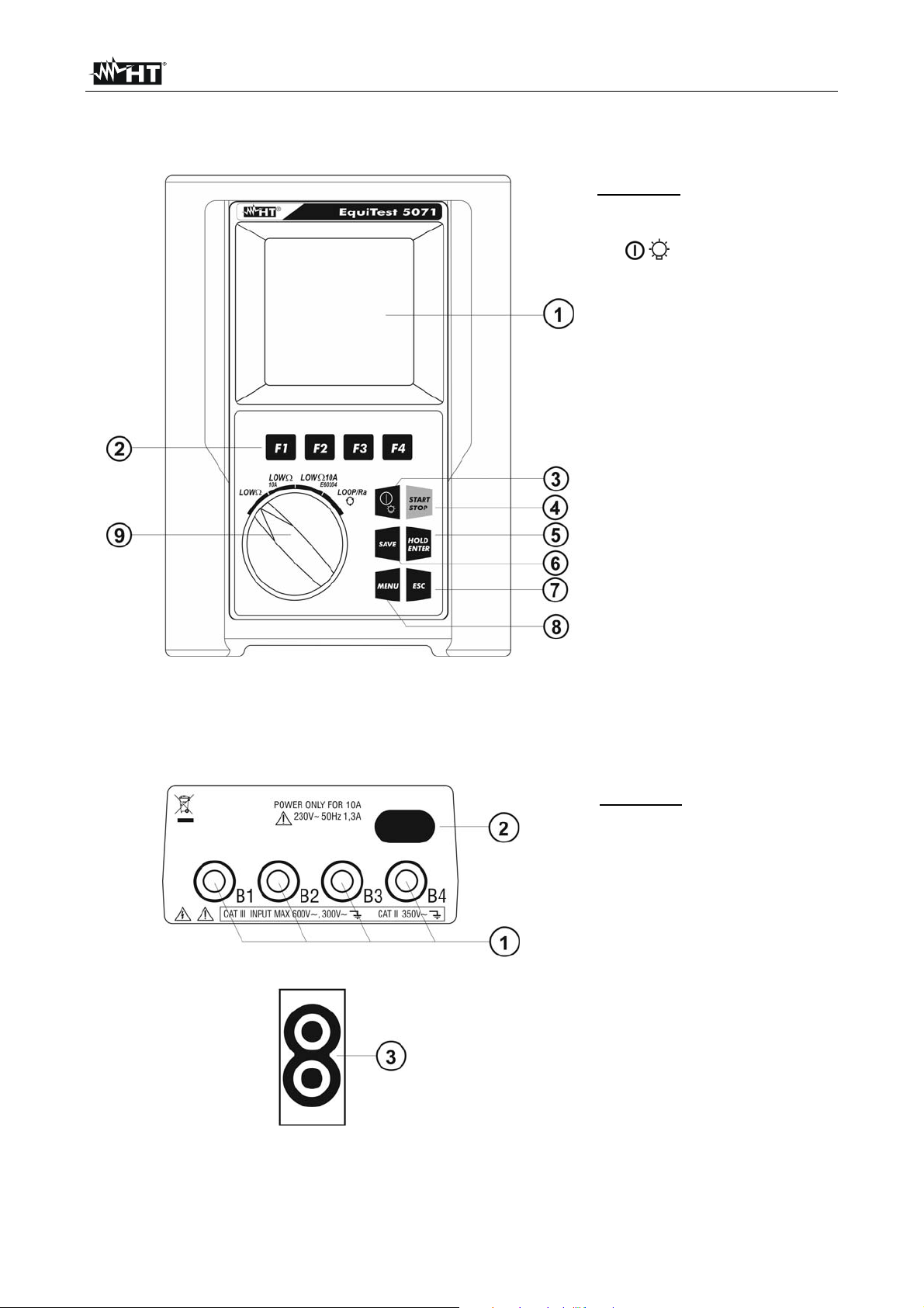
4.1. FRONT PANEL
CAPTION:
1. LCD display
2. F1, F2, F3, F4 keys
3. / key
4. START/STOP key
5. HOLD/ENTER key
6. SAVE key
7. ESC key
8. MENU key
9. Rotary selector switch
Fig. 1: Description of the instrument’s front panel
4.2. INPUT AND OUTPUT LEADS
CAPTION:
1. B1, B2, B3, B4 inputs
2. Input for external
230V/50Hz power supply
for functions LOW10A
and LOW10AE60204
3. Optical serial output for
PC connection
Fig. 2: Description of the instrument’s inputs and outputs
EN - 5
Page 8
EQUITEST 5071
4.3. DESCRIPTION OF FUNCTION KEYS
Key Description
Key to switch on/off the instrument. Press and hold the key for
/
some seconds to turn off the instrument. Shortly press this key
to activate display backlighting.
F1, F2, F3, F4
Keys for programming the internal parameters associated with
the functions of the instrument.
START/STOP Key for starting measuring. STOP function not enabled.
SAVE Key for saving measurement results.
HOLD/ENTER
ENTER key to confirm the parameters set within the general
menu of the instrument. HOLD function not enabled.
MENU Key to access the instrument’s general menu.
ESC Key to quit the selected mode shown on the display.
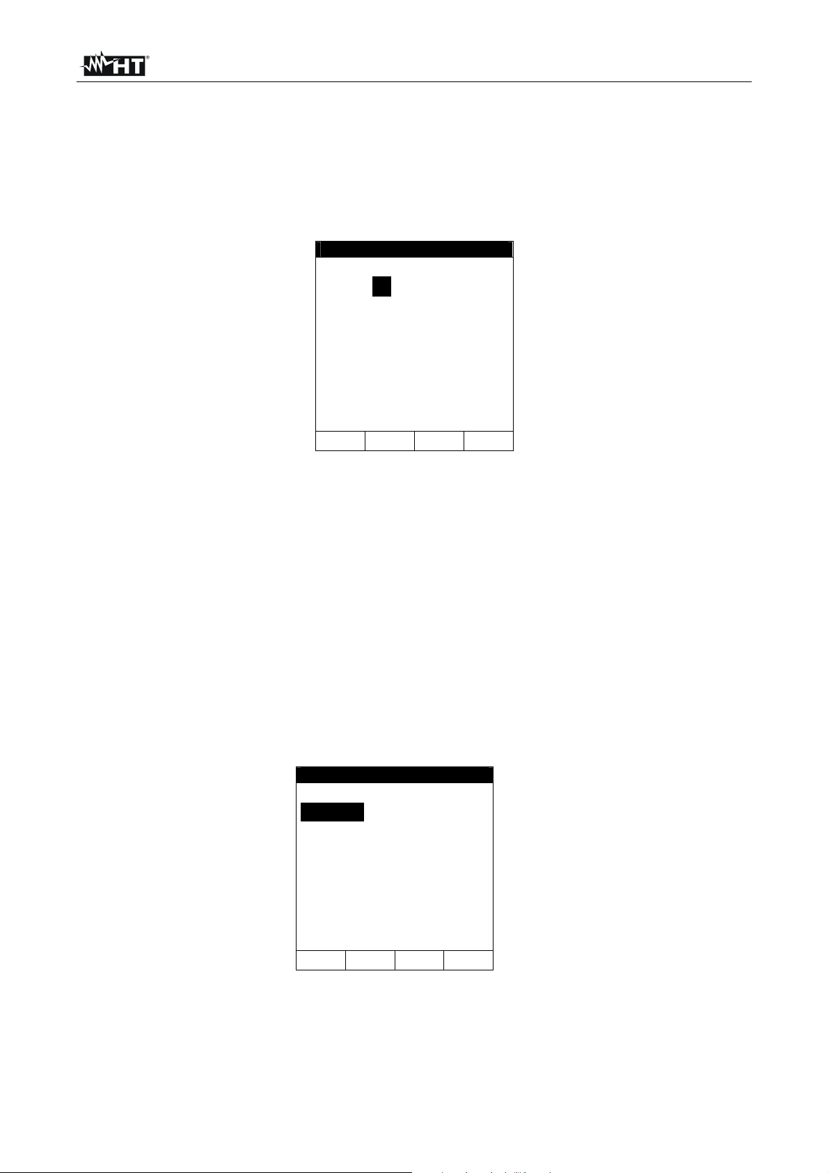
4.4. DISPLAY DESCRIPTION
The display is a graphic module with a resolution of 128 x 128 dots. The first line of the
display shows the instrument’s date and time. In the top right-hand corner of the display
there is the battery charge indicator.
LOW 30.11.12
----
R+ R-
---- ----
---mA ---mA
AUTO 0.11
FUNC CAL
For the sake of brevity, these symbols will be omitted in the following screenshots of this
manual.
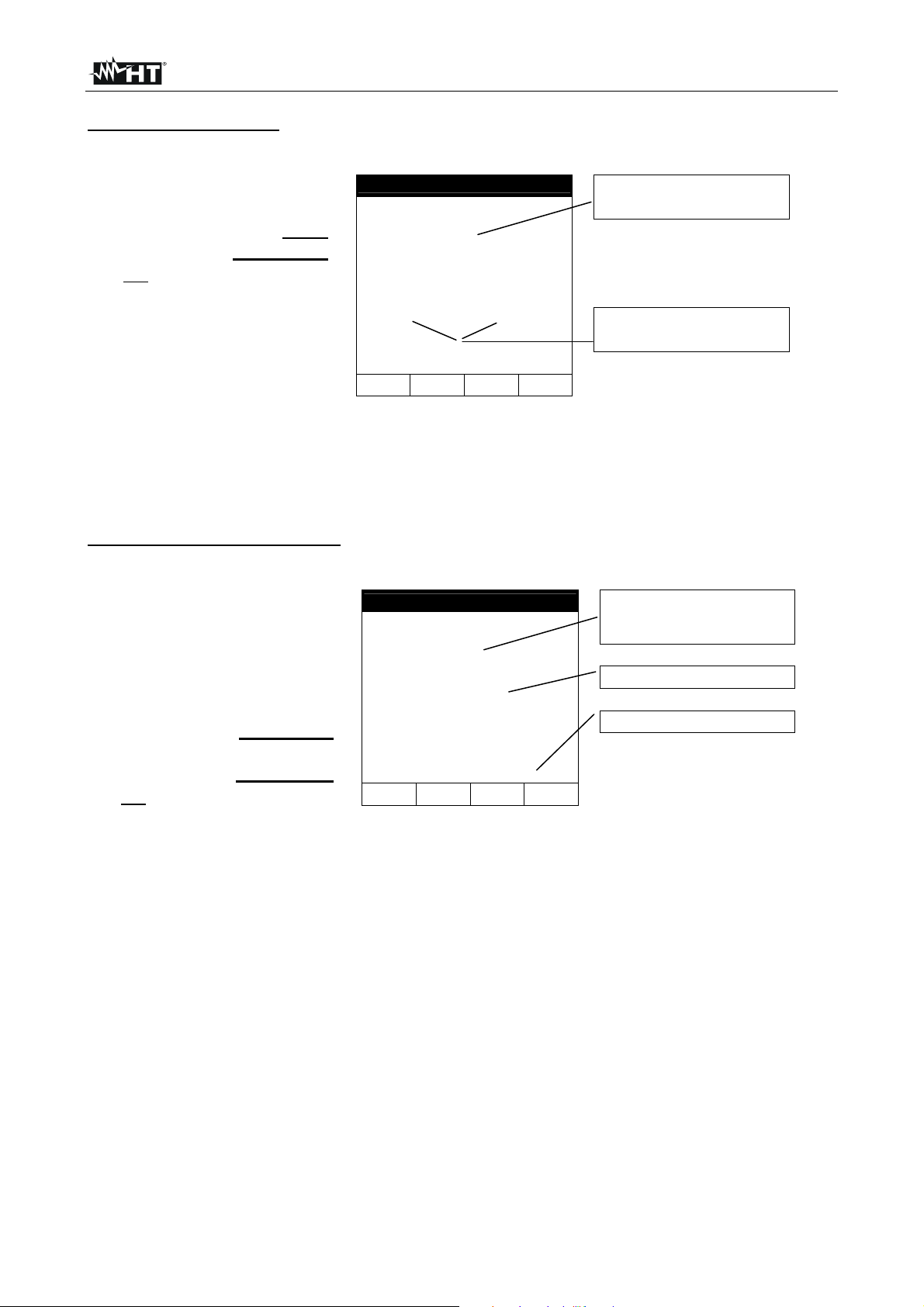
4.5. INITIAL SCREEN
When turning on the instrument with the / key, the following screen appears for a few
seconds:
It contains (further to the name of the Manufacturer and to
HT5071
the instrument model):
The serial number (SN:) of the instrument.
HT
SN:12345678 V: 1.59
Baud Rate 57600
CALIBRATION DATE:
30.11.12
The firmware version (V:) in the instrument's memory.
The date of the last instrument calibration
(CALIBRATION DATE).
The serial transmission speed (Baud Rate).
Press ESC to exit this screen.
EN - 6
Page 9
EQUITEST 5071
4.6. BACKLIGHT
During instrument operation, a further short pressing of the / key turns on the display’s
backlighting. In order to save battery efficiency, backlighting automatically turns off after
approx. 5 seconds. A frequent use of backlighting reduces the batteries’ life.
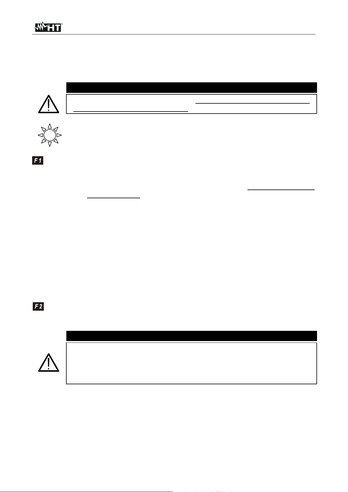
5. INITIAL SETTINGS
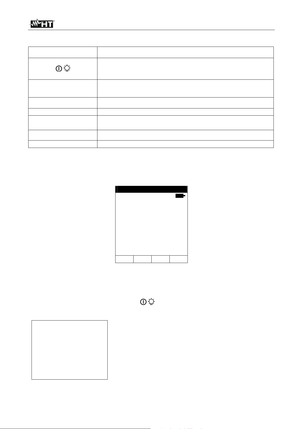
When pressing the MENU key, the display shows the following screen, which allows
accessing the General Menu:
GENERAL MENU
SAFETY TEST MEMORY
CONTRAST
DATE&TIME
LANGUAGE
The following items are available:
Safety Test Memory memory area for saving measuring results.
Contrast function to adjust display contrast.
Date&Time function to adjust system date/time.
Language function to select system language.
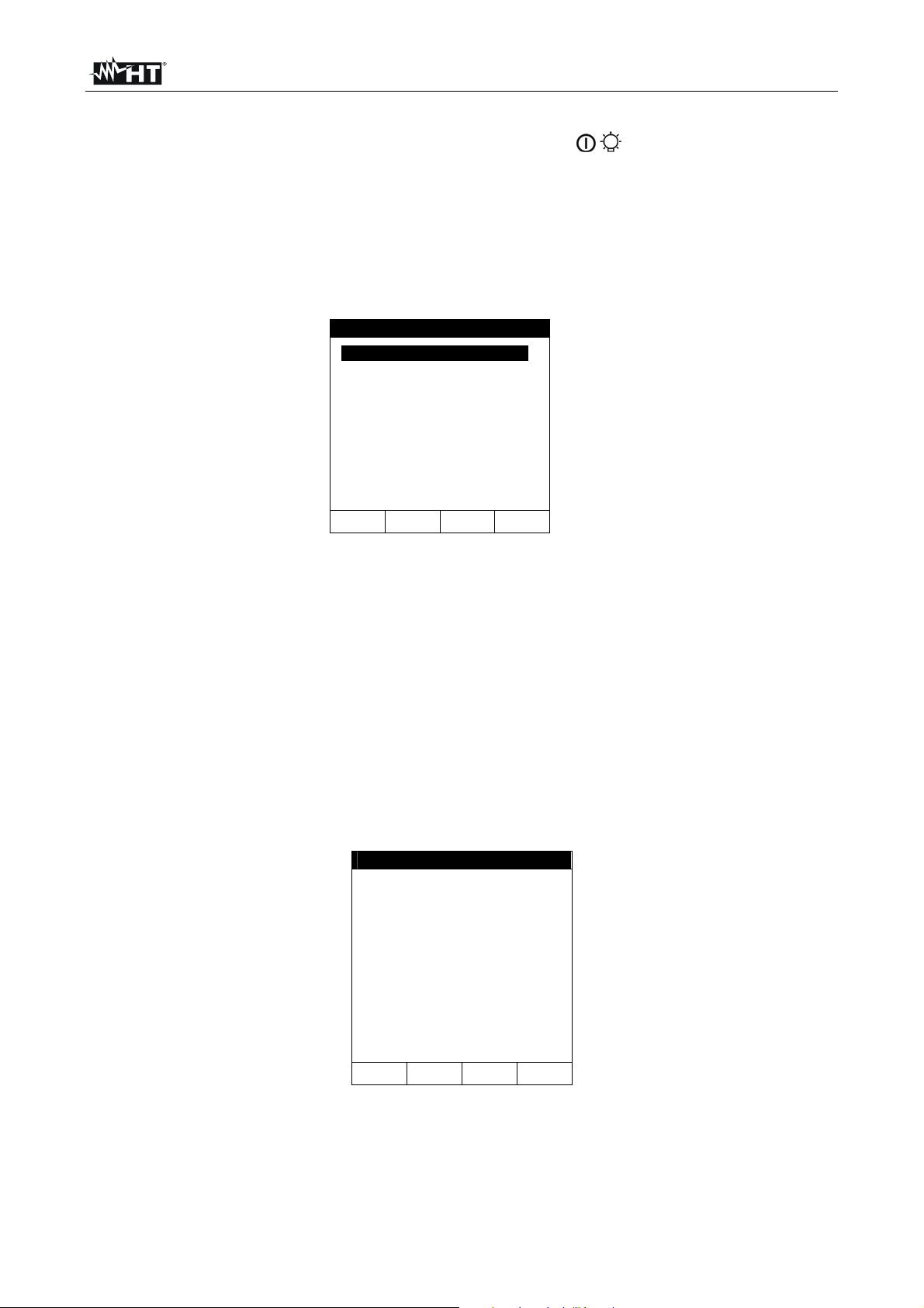
5.1. ADJUSTING DISPLAY CONTRAST
Proceed as follows:
1. Press the MENU key with the selector switch in any position to enter the General
Menu.
2. Use the F1 key to move the cursor to “CONTRAST”. Confirm with ENTER. The
following screen appears on the display:
CONTRAST
CONTRAST
35%
+ -
3. Use the F3 and F4 keys to set the desired percentage value.
4. Press the ENTER key to confirm. The settings made shall remain valid also after
switching off the instrument.
5. Press the ESC key to exit without saving.
EN - 7
Page 10
EQUITEST 5071
5.2. ADJUSTING DATE AND TIME
Proceed as follows:
1. Press the MENU key with the selector switch in any position to enter the General
Menu.
2. Use the F1 key to move the cursor to “DATE&TIME”. Confirm with ENTER. The
following screen appears on the display:
DATE&TIME
25 . 08 . 12
15 : 25 : 00
+ -
3. Use the F1 and F2 keys to alternately select the date and time fields. The selected field
appears with a black background. The date is expressed with format: “gg.mm.aa” while
time is expressed in format: “hh:mm:ss”
4. Use the F3 and F4 keys to increase or decrease the value of date/time.
5. Press the ENTER key to confirm. The settings made shall remain valid also after
switching off the instrument.
6. Press the ESC key to exit without saving.
5.3. LANGUAGE SETTING
Proceed as follows:
1. Press the MENU key with the selector switch in any position to enter the General
Menu.
2. Use the F1 key to move the cursor to “LANGUAGE”. Confirm with ENTER. The
following screen appears on the display:
LANGUAGE
ITALIAN
ENGLISH
SPANISH
GERMAN
FRENCH
3. Use the F1 and F2 keys to select the desired language among those available.
4. Press the ENTER key to confirm. The settings made shall remain valid also after
switching off the instrument.
5. Press the ESC key to exit without saving.
EN - 8
Page 11
EQUITEST 5071
6. OPERATING INSTRUCTIONS
6.1. LOW: CONTINUITY OF PROTECTIVE CONDUCTORS WITH 200mA
Measurement is carried out in compliance with standard IEC/EN61557-4.
Before carrying out the continuity test, make sure there is no voltage at the
ends of the conductor to be analyzed.
Turn the rotary switch to LOW.
With the F1 key it is possible to select one of the following measuring modes
(which cyclically appear when pressing the key):
“AUTO” mode (the instrument carries out two measurements with
inverted polarity and displays their average value). Recommended mode
for continuity test
“RT+” mode (measurement with positive polarity and with the possibility
of setting a duration time for testing). In this case, the operator may set a
sufficiently long measuring time to be able to move the protective
conductors while the instrument is carrying out the test, in order to find
out a possible bad connection.
“RT-” mode (measurement with negative polarity and with the possibility
of setting a duration time for testing). In this case, the operator may set a
sufficiently long measuring time to be able to move the protective
conductors while the instrument is carrying out the test, in order to find
out a possible bad connection.
With the F2 key it is possible to select the “CAL“ mode (compensation of the
resistance of the cables used for measuring).
CAUTION
CAUTION
Continuity test is carried out by applying a current higher than 200mA in
case resistance does not exceed 5 (including the measuring cables’
resistance saved as offset value in the instrument after carrying out the
calibration procedure). For higher resistance values, the instrument carries
out the test with a current lower than 200mA.
EN - 9
Page 12
EQUITEST 5071
A
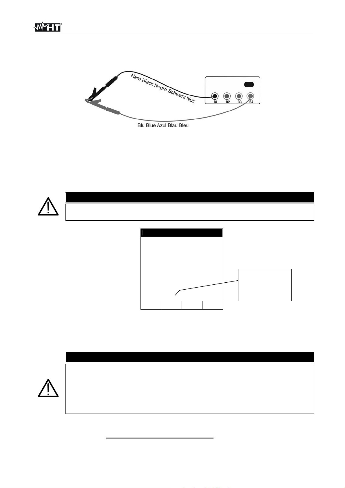
6.1.1. Calibration of measuring cables
1. Insert the black cable and the blue cable into the relevant input terminals B1 and B4 of
the instrument.
Fig. 3: Terminal connection during calibration procedure
2. If, for the measurement to be carried out, the length of the cables provided should be
insufficient, extend the blue cable.
3. Insert two alligator clips into the cable terminals.
4. Short-circuit the measuring cables’ ends, taking care that the conductive parts of the
alligator clips have good contact (see Fig. 3)
5. Press the F2 key. The instrument calibrates.
CAUTION
Never disconnect the terminals from the measuring points when the
instrument shows the message "MEASURING…".
LOW 30.11.12
----
R+ R-
---- ----
---mA ---mA
UTO 0.11
FUNC CAL
This numerical
value indicates
that calibration has
been carried out
6. At measurement end, the instrument gives out a double sound, to indicate that
calibration has been correctly carried out. The value of calibration is updated and
displayed above the F2 key. This value shall remain saved also after the instrument
has been switched off.
CAUTION
The instrument calibrates the measuring cables only if their resistance is
lower than 5
Before carrying out any measurement, always make sure that calibration
is referred to the cables currently used. In a continuity test, if the purified
resistance value (i.e. the value of resistance minus the calibration offset
value) is negative, the symbol “CAL” flashes on the display.
7. To delete the calibration parameter it is necessary to carry out a calibration
procedure with a lead resistance higher than 5 (e.g. with open leads). When
carrying out a deletion, the symbol “- - -“ is shown on the display above the F2 key.
EN - 10
Page 13
EQUITEST 5071
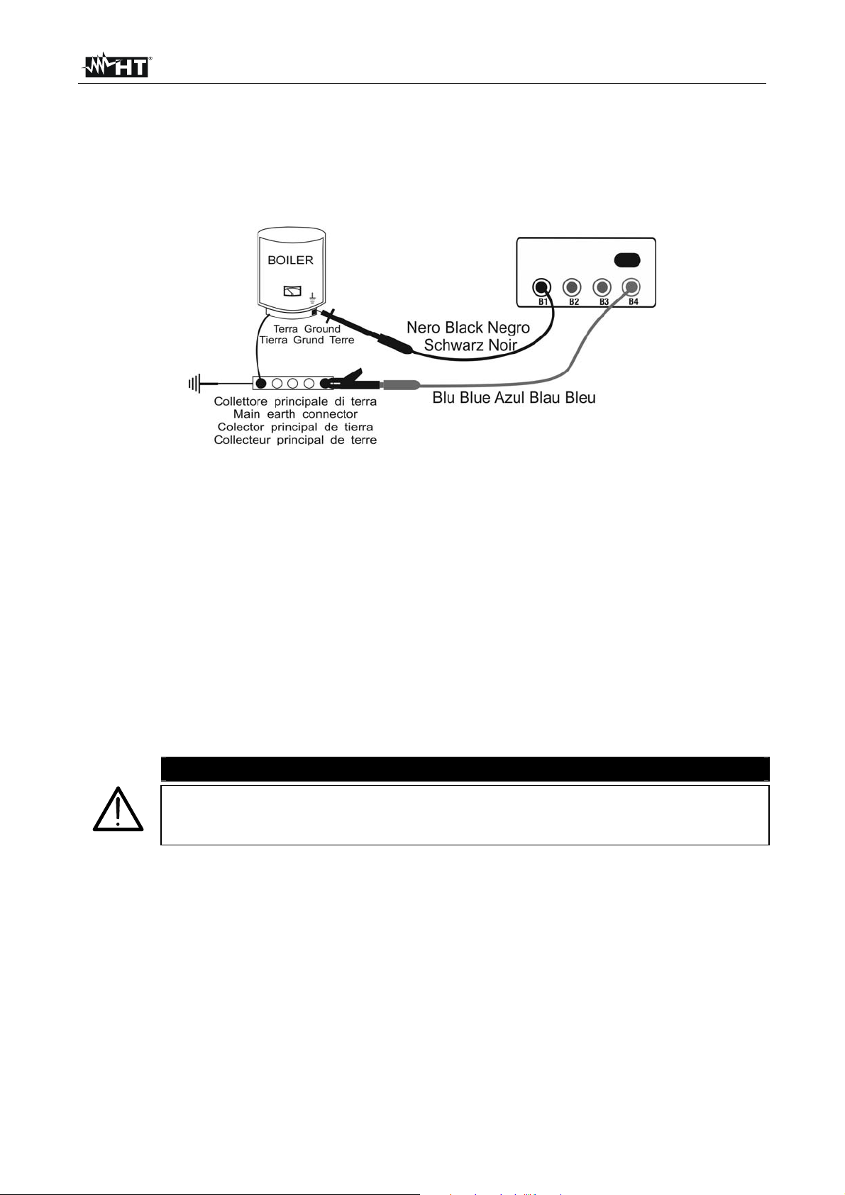
6.1.2. Measuring
1. Select the desired mode using the F1 key.
2. Insert the black cable and the blue cable into the relevant input terminals B1 and B4 of
the instrument:
Fig. 4: Instrument connection for LOW test
3. If, for the measurement to be carried out, the length of the cables provided should be
insufficient, extend the blue cable.
4. Insert two alligator clips into the cable terminals.
5. Short-circuit the measuring cables’ ends, taking care that the conductive parts of the
alligator clips have good contact. Press the START/STOP key. If the instrument
shows a resistance value different from 0,00 repeat the calibration operation (see
§ 6.1.1)
6. Connect the instrument terminals to the ends of the conductor whose continuity you
want to test (see Fig. 4)
7. If mode "RT+" or "RT-" is selected, use the F3, F4 keys to set the test time.
8. Press the START/STOP key. The instrument carries out the measurement. In "RT+" or
"RT-" mode, press the START/STOP key again to stop the test.
CAUTION
When message "MEASURING…" is displayed, this indicates that the
instrument is carrying out the test. Never disconnect the instrument’s leads
during this phase.
EN - 11
Page 14
EQUITEST 5071
A
A
T
"AUTO" mode results
t the end of the test, in
case the average value
of resistance Ravg
measured is lower than
5, the instrument gives
out a double sound to
signal the positive
result of the test. The
following screen
appears on the display:
LOW 30.11.12
1.05
R+ R-
1.07 1.03
219mA 219mA
AUTO 0.11
FUNC CAL
verage value of
resistance Ravg
Value of test current
The results can be saved by pressing the SAVE key twice (see § 7.1).
"RT+" or “RT-" mode results
During the test, an
audible beep sounds in
case the measured
resistance value exceeds
99.9.
If, at the end of the test,
the maximum RT+ or RT-
resistance value
measured is lower than
5, the instrument gives
out a double sound to
LOW 30.11.12
1.07
RT+ 0.11
FUNC CAL
219mA
IME: 10s
Maximum value of
resistance measured
during test
Test current
Duration of test
signal the positive
result of the test. The
following screen appears
on the display:
The results can be saved by pressing the SAVE key twice (see § 7.1).
EN - 12
Page 15

EQUITEST 5071
6.1.2.1. Anomalous situations in "AUTO", "RT+", "RT-" mode
If the instrument detects
a voltage higher than
approx. 15V at the input
terminals, the message
to the side appears on
the display.
If the instrument detects
that:
R
CALIBRATION
the message to the side
appears on the display.
> R
MEASURED
LOW 30.11.12
R+ R-
-.-- -.--
---mA ---mA
AUTO 0.11
FUNC CAL
LOW 30.11.12
R+ R-
0.00 0.00
219mA 219mA
AUTO 0.11
FUNC CAL
-.- -
VOLT IN INPUT
0.00
CAL > RES
The test cannot be
carried out because
voltage has been
detected at the
instrument’s inputs
CAUTION:
R
CALIBRATION
> R
MEASURED
In case a resistance
higher or equal to 5
but lower than 99,9 is
detected, at the end of
the test the instrument
gives out a long sound
and the following screen
appears on the display.
PREVIOUS RESULTS CANNOT BE SAVED.
LOW 30.11.12
5.17
R+ R-
5.17 5.17
209mA 209mA
AUTO 0.11
FUNC CAL
Resistance higher than 5
Test current
The results can be saved by pressing the SAVE key twice (see § 7.1).
In case a resistance
higher than 99,9 is
detected, at the end of
the test the instrument
gives out a long sound
and the following screen
appears on the display.
LOW 05.06.12
> 99.9
R+ R-
-.-- -.--
---mA ---mA
AUTO 0.11
FUNC CAL
Resistance with a value
higher than 99.9
CAUTION: Resistance
value out of range
The results can be saved by pressing the SAVE key twice (see § 7.1).
EN - 13
Page 16

EQUITEST 5071
6.2. LOW10A: CONTINUITY OF PROTECTIVE CONDUCTORS WITH 10A
Measurement is carried out in compliance with standards IEC/EN60439-1.
Measurement is carried out by voltammetric method with 4 wires. Therefore, the calculated
value is not influenced by the value of resistance of the measuring cables, so it is not
necessary to carry out any preventive calibration of the cables used for measuring (unlike
with function LOW).
CAUTION
Before carrying out the continuity test, make sure there is no voltage at the
ends of the conductor to be analyzed.
Measurement may be influenced by parallel impedance of additional
circuits or by transient currents. Make sure none of these parasite
elements is present before measuring and always keep test cables
outstretched in order to prevent “coil effects”.
CAUTION
The instrument performs the test with a current 10A only if resistance is
lower than approx. 0.45.
6.2.1. Measuring
1. Turn the rotary switch to LOW10A. The following screen appears on the display:
LOW 10A 30.11.12
-----
RLIM: 0.100
----A
2. Use the F3 and F4 keys to set the maximum limit threshold RLIM for measurement in
range 0.001 0.999. Keep the function keys pressed for a quick setting of the
desired value
3. Supply the instrument by connecting it to the 230V/50Hz electric mains (see Fig. 2 –
position 2) by means of the cable provided.
4. Connect the connectors of the measuring cables C7000 provided to the instrument’s
input terminals B1 (Black), B2 (Red), B3 (Red), B4 (Black) and the alligator clips to the
item to be tested as indicated in Fig. 5
EN - 14
Page 17

EQUITEST 5071
A
Fig. 5: Instrument connection for LOW10A test
5. Press the START key. The instrument starts testing.
CAUTION
When message "MEASURING…" is displayed, this indicates that the
instrument is carrying out the test. Never disconnect the instrument’s leads
during this phase.
t the end of the test, the
instrument gives out a
double sound to indicate
that test has been
correctly performed and
the following screen
appears on the display.
LOW 10A 31.11.12
0.107
13.4A
RLIM:0.100
Measured resistance
Test current
6. The displayed results can be saved by pressing the SAVE key twice (see § 7.1).
EN - 15
Page 18

EQUITEST 5071
R
6.2.2. Anomalous situations
If the instrument does not
detect any power supply
at connector "230V 50Hz",
it displays the message
reported to the side.
LOW 10A 31.11.12
-----
----A
NO POWER SUPPLY
LIM=0.100
If the instrument detects
a resistance higher than
the limit set, it gives out
a long sound and the
following screen
appears on the display.
LOW 10A 31.11.12
0.323
9.12A
RLIM=0.100
Symbol indicates a
resistance higher than the
limit set.
Test current
The displayed results can be saved by pressing the SAVE key twice (see § 7.1).
If the instrument detects
a resistance higher than
the maximum
measurable value, it
gives out a long sound
and the following screen
appears on the display.
LOW 10A 31.11.12
>0.999
9.12A
RLIM=0.100
Symbol ">" indicates a
resistance higher than the
maximum measurable
value.
Test current
The displayed results can be saved by pressing the SAVE key twice (see § 7.1)
EN - 16
Page 19

EQUITEST 5071
6.3. LOW10AE204: CONTINUITY 10A IN COMPLIANCE WITH IEC/EN602041:2006
Measurement is carried out in compliance with standard IEC/EN60204-1:2006, which
states that measurement result must be compatible with the protective conductor’s length,
section and material.
The instrument evaluates the limit threshold of measured resistance according to the
following formula:
L
lim
R
S
in which:
L = length in m of the protective conductors being tested, decided by the user
according to design calculations;
S= section in mm2 of the protective conductor being tested;
= resistivity of copper set to the standard average value of 0.017mm2/m.
Measurement is carried out by voltammetric method with 4 wires. Therefore, the calculated
value is not influenced by the value of resistance of the measuring cables, so it is not
necessary to carry out any preventive calibration of the cables used for measuring (unlike
with function LOW).
CAUTION
Before carrying out the continuity test, make sure there is no voltage at the
ends of the conductor to be analyzed.
Measurement may be influenced by parallel impedance of additional
circuits or by transient currents. Make sure none of these parasite
elements is present before measuring and always keep test cables
outstretched in order to prevent “coil effects”.
CAUTION
The instrument performs the test with a current 10A only if resistance is
lower than approx. 0.45.
EN - 17
Page 20

EQUITEST 5071
6.3.1. Measuring
1. Turn the rotary switch to LOW10AE204. The following screen appears on the display:
LOW10AE204 30.11.12
-----
LEN: 10.0 SEC: 4.0
----A
2. Use the F1 and F2 keys to set the length in range 0.1m 999.9m and keys F3 and F4
to set the section of the protective conductor being tested, selecting the values 0.5, 1,
1.5, 2.5, 4, 6, 10, 16mm2. Keep the function keys pressed for a quick setting of the
desired values
3. Supply the instrument by connecting it to the 230V/50Hz electric mains (see Fig. 2 –
position 2) by means of the cable supplied.
4. Connect the connectors of the measuring cables C7000 provided to the instrument’s
input terminals B1 (Black), B2 (Red), B3 (Red), B4 (Black) and the alligator clips to the
item to be tested as indicated in Fig. 6
Fig. 6: Instrument connection for LOW10AE204 test
EN - 18
Page 21

EQUITEST 5071
A
5. Press the START key. The instrument starts testing.
CAUTION
When message "MEASURING…" is displayed, this indicates that the
instrument is carrying out the test. Never disconnect the instrument’s leads
during this phase.
t the end of the test, the
instrument gives out a
double sound to indicate
that test has been
correctly performed and
the following screen
appears on the display.
LOW 10A 31.11.12
0.012
22.7A
LEN: 10.0 SEC: 4.0
Measured resistance
Test current
6. The displayed results can be saved by pressing the SAVE key twice (see § 7.1).
EN - 19
Page 22

EQUITEST 5071
6.3.2. Anomalous situations
If the instrument does not
detect any power supply
at connector "230V 50Hz",
it displays the message
reported to the side.
LOW10AE204 30.11.12
-----
----A
NO POWER SUPPLY
LEN: 10.0 SEC: 4.0
If the instrument detects
a resistance higher than
the limit set, it gives out
a long sound and the
following screen
appears on the display.
LOW10AE204 30.11.12
0.323
9.12A
LEN: 10.0 SEC: 4.0
Symbol indicates a
resistance higher than the
limit set.
Test current
The displayed results can be saved by pressing the SAVE key twice (see § 7.1).
If the instrument detects
a resistance higher than
the maximum
measurable value, it
gives out a long sound
and the following screen
appears on the display.
LOW10AE204 30.11.12
>0.999
9.12A
LEN: 10.0 SEC: 4.0
Symbol ">" indicates a
resistance higher than the
maximum measurable
value.
Test current
The displayed results can be saved by pressing the SAVE key twice (see § 7.1)
EN - 20
Page 23

EQUITEST 5071
6.4. LOOP/RA : LOOP IMPEDANCE, OVERALL EARTH RESISTANCE AND
PHASE SEQUENCE
Measurement is carried out in compliance with standards IEC/EN61557-3 and
IEC/EN60204-1:2006.
Turn the rotary switch to LOOP/Ra .
With the F1 key it is possible to select one of the following measuring modes
(which cyclically appear when pressing the key):
“P-N” mode (the instrument measures impedance between Phase
conductor and Neutral conductor and calculates the assumed PhaseNeutral short-circuit current. This test is usually carried out to evaluate if
the breaking power of switches is higher than short-circuit current in the
installation point).
“P-P” mode (the instrument measures impedance between two Phase
conductors and calculates the assumed Phase-Phase short-circuit
current. This test is usually carried out to evaluate if the breaking power
of switches is higher than short-circuit current in the installation point).
“P-PE” mode (the instrument measures the overall earth resistance and
calculates the assumed Phase-Earth short-circuit current. This test is
usually carried out to evaluate the coordination of the protections against
indirect contact by means of an automatic interruption of power supply
and to measure the value of Earth resistance).
“RA” mode (the instrument measures the overall earth resistance and
calculates the assumed Phase-Earth short-circuit current. This test is
usually carried out to evaluate the coordination of the protections against
indirect contact by means of an automatic interruption of power supply
and to measure the value of Earth resistance. This test has a lower
resolution than “P-PE” test, but has the advantage that it can be carried
out without making a possible residual current protection, installed
upstreams of the measuring point, trip).
“ ” mode (the instrument detects phase sequence).
When message "MEASURING…" is displayed, this indicates that the
instrument is carrying out the test. Never disconnect the instrument’s leads
during this phase.
CAUTION
EN - 21
Page 24

EQUITEST 5071
3
6.4.1. High-resolution impedance measurement (0.1 m)
The instrument allows measuring impedance with a high resolution next to a MT/BT
transformer by using the optional accessory IMP57. Measurement is selectable in modes
LOOP P-P, P-N, P-PE by means of the F2 key (Z2). In case high-resolution impedance
measurement is selected with no connection of the accessory IMP57, the instrument shows a
screen similar to the following one (e.g.: Loop P-N):
LOOP
V1-2= 0V FRQ= 0.0Hz
P-N Z2
Z=-----
R=----- X=-----
IkSTD=----A
NO IMP57
FUNC ZSTD ICAL RMT
0.11.12
For any detail regarding the use and the technical specifications of accessory IMP57,
please refer to the relevant user manual or visit the website www.ht-instruments.com.
6.4.2. "P-N" mode: measurement procedure and results
1. Select the P-N mode using the F1 key.
2. Insert the 3 Black, Green, Blue connectors of the three-pin shuko cable or of the separate
cables into the relevant instrument input terminals B1, B3, B4 (see F ig. 7, Fig. 8). In case
separate cables are used, insert alligator clips on the free cable ends.
Fig. 7: Connection for measuring Loop
impedance of single-phase/two-phase
Fig. 8: Connection for measuring Loop
impedance of three-phase 400V system
230V system
3. Insert the Shuko plug into a 230V 50Hz socket or the alligator clips onto the conductors
of the three-phase system (see Fig. 7, Fig. 8)
4. When possible, disconnect all loads connected downstreams of the measuring point since
the impedance of these users may alter test results.
5. Press the START key. The instrument carries out the test.
EN - 22
Page 25

EQUITEST 5071
A
3
CAUTION
The following test entails the circulation of a maximum current of approx. 6A
between phase and neutral. This could cause the tripping of possible
magnetothermal protections with lower tripping currents. In this case, carry
out the measurement upstreams of the protections.
CAUTION
When message "MEASURING…" is displayed, this indicates that the
instrument is carrying out the test. Never disconnect the instrument’s leads
during this phase.
t the end of the test,
the instrument gives out
a double sound to
indicate that test has
been correctly
performed and the
following screen
appears on the display.
LOOP
1.07
FRQ=50.0HZ
VP-N=231V VP-PE=231V
P-N
FUNC Z2
215A
0.11.12
Value of Phase-Neutral Line
impedance expressed in
Ohm
Value of the assumed PhaseNeutral short-circuit current
calculated using the formula
reported below
Formula used for calculating the assumed short-circuit current:
U
I
CC
N
Z
PN
where U
= Phase-Neutral voltage 127 if V
N
230 if 150V< V
150
mis
mis
260
Z
= measured Phase-Neutral impedance
PN
6. The results can be saved by pressing the SAVE key twice (see § 7.1).
EN - 23
Page 26

EQUITEST 5071
A
3
6.4.3. "P-P" mode: measurement procedure and results
1. Select the P-P mode using the F1 key.
2. Insert the 3 Black, Green, Blue connectors of the separate cables into the relevant
instrument input terminals B1, B3, B4.
Fig. 9: Instrument connection for measuring Phase-Phase impedance
3. Insert the alligator clip s onto the conductors of the three-phase system (see Fig. 9)
4. When possible, disconnect all loads connected downstreams of the measuring point
since the impedance of these users may alter test results
5. Press the START key. The instrument carries out the test.
CAUTION
The following test entails the circulation of a maximum current of approx.
12A (400V) between phase and phase. This could cause the tripping of
possible magnetothermal protections with lower tripping currents. In this
case, carry out the measurement upstreams of the protections.
When message "MEASURING…" is displayed, this indicates that the
instrument is carrying out the test. Never disconnect the instrument’s
leads during this phase.
t the end of the test,
the instrument gives out
a double sound to
indicate that test has
been correctly
performed and the
following screen
appears on the display.
Operating mode
Formula used for calculating the assumed short-circuit current:
where UN = Phase-Phase voltage 127 if V
Z
LOOP
0.57
FRQ=50.0HZ
VP-P=402V VP-PE=231V
P-P
FUNC Z2
= measured Phase-Phase impedance
PP
701A
0.11.12
230 if 150V< V
400 if V
Value of Phase-Phase Line
impedance expressed in
Ohm
Value of the assumed PhasePhase short-circuit current
calculated using the formula
reported below
U
N
Z
PP
mis
> 260
mis
150
mis
260
I
CC
3. The results can be saved by pressing the SAVE key twice (see § 7.1).
EN - 24
Page 27

EQUITEST 5071
6.4.4. "P-PE" mode: measurement procedure and results
1. Select the P-PE mode using the F1 key.
2. Insert the 3 Black, Green, Blue connectors of the shuko cable or of the separate cables into
the relevant instrument input terminals B1, B3, B4 (see Fig. 10, Fig. 11, Fig. 12). In case
separate cables are used, insert alligator clips on the free cable ends.
Fig. 10: Connection for measuring P-PE
impedance of single-phase/two-phase
230V system
Fig. 11: Connection for measuring P-PE
impedance of three-phase 400V + N
system
Fig. 12: Connection for P-PE impedance of three-phase 230V o 400V system without N
3. Insert the Shuko plug into a 230V 50Hz socket or the alligator clips onto the conductors
of the three-phase system (see Fig. 10, Fig. 11, Fig. 12)
4. The F4 key allows setting the limit value for contact voltage. The instrument carries out
the test, checking that the contact voltage found on the system masses, with regard to
the actual current applied, does not exceed the limit value set. You may select one of
the two possible values: 50V (default), 25V
5. Press the START key once. The instrument carries out the test by circulating a current
of type "0°". Otherwise, press the START key twice before the dashes disappear. The
instrument carries out the test by circulating a current of type "180°".
CAUTION
The following test entails the circulation of a current of approx. 6A
between phase and earth. This could cause the tripping of possible
magnetothermal or residual current protections. In this case, carry out the
measurement upstreams of the protection. In case of AC residual current
protections you may try and detect what kind of waveform (type 0° or type
180°) does not cause the protection’s tripping.
When message "MEASURING…" is displayed, this indicates that the
instrument is carrying out the test. Never disconnect the instrument’s
leads during this phase.
EN - 25
Page 28

EQUITEST 5071
A
3
t the end of the test,
the instrument gives out
a double sound to
indicate that test has
been correctly
performed and the
following screen
appears on the display.
LOOP
1.07
Freq=50.0HZ
VP-N=231V Vp-PE=231V
P-PE
FUNC Z2
215A
0.11.12
Value of Phase-Earth
impedance expressed in .
Value of the assumed PhasePhase short-circuit current
calculated using the formula
reported below
Operating mode
N.B.: In TT systems, the value of impedance measured by the instrument may only be
attributed to the value of overall earth resistance. Therefore, in compliance with
standard CEI 64-8, the measured value may be taken as the value of the system’s
earth resistance.
U
Formula used for calculating the assumed short-circuit current:
I
CC
N
Z
PE
where: UN = Phase-Earth voltage 127 if
100< V
Z
150
mis
230 if 150V< V
= measured Phase-Earth impedance
PE
mis
260
6. The results can be saved by pressing the SAVE key twice (see § 7.1).
EN - 26
Page 29

EQUITEST 5071
6.4.5. "RA" mode: measurement procedure and results
1. Select the RA mode using the F1 key.
2. Insert the 3 Black, Green, Blue connectors of the shuko cable or of the separate cables into
the relevant instrument input terminals B1, B3, B4 (see Fig. 13, Fig. 14, Fig. 15). In case
separate cables are used, insert alligator clips on the free cable ends.
Fig. 13: Connection for Ra measuring of
single-phase/two-phase 230V system
Fig. 14: Connection for Ra measuring of
three-phase 400V + N system
Fig. 15: Connection for Ra measuring of three-phase 230V o 400V system without N
3. Insert the Shuko plug into a 230V 50Hz socket or the alligator clips onto the conductors
of the three-phase system (see Fig. 13, Fig. 14, Fig. 15)
4. The F4 key allows setting the limit value for contact voltage. The instrument carries out
the test, checking that the contact voltage found on the system masses, with regard to
the actual current applied by the instrument, does not exceed the limit value set for
contact voltage. You may select one of the two possible values: 50V (default), 25V
5. Press the START/STOP key once. The instrument carries out the test by circulating a
current of type "0°". Otherwise, press the START/STOP key twice before the dashes
disappear. The instrument carries out the test by circulating a current of type "180°".
CAUTION
The following test entails the circulation of a current of approx. 15mA
between phase and earth. This could cause the tripping of possible
residual current protections with rated current of 10mA. In this case, carry
out the measurement upstreams of the protection.
When message "MEASURING…" is displayed, this indicates that the
instrument is carrying out the test. Never disconnect the instrument’s
leads during this phase.
EN - 27
Page 30

EQUITEST 5071
A
3
A
t the end of the test,
the instrument gives out
a double sound to
indicate that test has
been correctly
performed and the
following screen
appears on the display.
Operating mode
LOOP
1.07
Freq=50.0HZ
VP-N=231V Vp-PE=231V
R
FUNC
215A
0.11.12
Value of Phase-Earth
resistance expressed in
Value of the assumed PhaseEarth short-circuit current
calculated using the formula
reported below
N.B. In TT systems, the value of overall earth resistance may be considered similar to
the value of Phase-Earth fault loop impedance, measured by the instrument.
Therefore, in compliance with standards, the measured value may be taken as the
value of the system’s earth resistance.
Formula used for calculating the assumed short-circuit current:
U
I
CC
N
Z
PE
where: UN = Phase-Earth voltage 127 if
100< V
Z
150
mis
230 if 150V< V
= measured Phase-Earth impedance
PE
mis
260
6. The results can be saved by pressing the SAVE key twice (see § 7.1).
EN - 28
Page 31

EQUITEST 5071
A
3
6.4.6. " " mode: measurement procedure and results
1. Select the " " mode using the F1 key.
2. Insert the 3 Black, Blue, Green connectors of the separate cables into the relevant
instrument input terminals B1, B2, B3.
Fig. 16: Instrument connection for phase sequence test
3. Insert the alligator clips onto the conductors of the three-phase system (see Fig. 16)
4. Press the START key. The instrument carries out the test.
CAUTION
When message "MEASURING…" is displayed, this indicates that the
instrument is carrying out the test. Never disconnect the instrument’s leads
during this phase.
t the end of the test,
the instrument gives out
a double sound to
indicate that test has
been correctly
performed and the
following screen
appears on the display.
Operating mode
123
FRQ=50.0HZ V1-2=391V
V2-3=401V V3-1=399V
PHASE ROTATION
FUNC
OK
0.11.12
Phase sequence indication
123
Phase-Phase voltage values
Correct phase sequence
5. The results can be saved by pressing the SAVE key twice (see § 7.1).
CAUTION
Message “123” DOES NOT mean that Input B1 is connected to phase L1,
Input B2 is connected to phase L2 and Input B3 is connected to phase L3,
but it only indicates that the phases of the electric system being tested
respect the correct sequence.
EN - 29
Page 32

EQUITEST 5071
6.4.6.1. Anomalous situations in "P-P", "P-N", "P-PE","RA", " " mode
If the instrument detects
a Phase-Neutral voltage
and a Phase-Earth
voltage lower than
100V, the following
message appears on
the display. Check that
the system being tested
is supplied.
If the instrument detects
a Phase-Neutral voltage
and a Phase-Earth
voltage higher than
250V, or a Phase-Phase
voltage higher than
440V, the following
message appears on
the display. Check that
the instrument is not
connected phase to
phase.
If the instrument detects
that the Phase and
Neutral terminals have
been exchanged, the
following message
appears on the display.
Rotate the Shuko plug
or check the connection
of the separate cables.
If the instrument detects
that the Phase and
Earth terminals have
been exchanged, the
following message
appears on the display.
Rotate the Shuko plug
or check the connection
of the separate cables.
LOOP 30.11.12
- - -
FRQ=50.0HZ
VP-N= 1V VP-PE= 0V
P-PE 50V
FUNC Z2 UL
LOOP 30.11.12
- - -
Freq=50.0HZ
VP-N=401V VP-PE=230V
HIGH VOLTAGE
P-PE 50V
FUNC Z2 UL
LOOP 30.11.12
- - -
FRQ=50.0HZ
VP-N=231V VP-PE= 0V
P-PE 50V
FUNC Z2 UL
LOOP 30.11.12
- - -
FRQ=50.0HZ
VP-N= 1V VP-PE= 230V
P-N
FUNC Z2
---A
LOW VOLTAGE
---A
---A
CHANGE P-N
---A
CHANGE P-PE
Insufficient voltage
Voltage too high
Phase and Neutral
conductors have been
exchanged.
Phase and Earth
conductors have been
exchanged.
EN - 30
Page 33

EQUITEST 5071
A
If in a 230V system, the
instrument detects that
terminals B3 and B4
have been exchanged,
the following message
appears on the display.
Check the connection of
the separate cables.
If the instrument detects
that, in case test is
carried out, a Contact
Voltage higher than the
limit value set would be
found in the system
being tested, it does not
perform the test and the
following message
appears on the display.
Check for the efficiency
of the PE conductor and
of the grounding system.
If the instrument detects
an Earth resistance so
high that the Earth
conductor of the
grounding system itself
may be considered
missing, the following
message appears on
the display. Check for
the efficiency of the PE
conductor and of the
grounding system.
If, after repeated tests,
the instrument has
overheated, the
following message
appears on the display.
Wait for the message to
disappear before
carrying out other tests.
LOOP 30.11.12
- - -
FRQ=50.0HZ
VP-N=131V VP-PE= 227V
P-N
FUNC Z2
LOOP 30.11.12
- - -
FRQ=50.0HZ
VP-N= 1V Vp-PE= 0V
R
50V
FUNC UL
LOOP 30.11.12
- - -
FRQ=50.0HZ
VP-N=231V Vp-PE= 40V
P-PE 50V
FUNC Z2 UL
LOOP 30.11.12
- - -
FRQ=50.0HZ
VP-N=231V Vp-PE= 40V
P-PE 50V
FUNC Z2 UL
---A
CHANGE N-PE
---A
Ut DANGEROUS
---A
NO PE
---A
HIGH TEMP
Phase and Earth
conductors have been
exchanged.
The instrument detects a
dangerous Contact Voltage
Inefficient grounding
system
The instrument has
overheated
EN - 31
Page 34

EQUITEST 5071
3
A
Using modes "P-P", "P-
N", if the instrument
detects an impedance
higher than 199.9, the
following screen
appears on the display.
LOOP 30.11.12
>199.9
FRQ =50.0HZ
VP-N= 1V VP-PE= 0V
P-N
FUNC Z2
---A
Symbol ">" indicates that
the value of impedance is
higher than the maximum
measurable value
The results can be saved by pressing the SAVE key twice (see § 7.1).
Using modes "P-PE",
"RA", if the instrument
detects an impedance
higher than 1999, the
following screen
appears on the display.
LOOP
>1999
FRQ =50.0HZ
VP-N= 1V VP-PE= 0V
R
50V
FUNC UL
---A
0.11.12
Symbol ">" indicates that
the value of impedance is
higher than the maximum
measurable value
The results can be saved by pressing the SAVE key twice (see § 7.1).
EN - 32
Page 35

EQUITEST 5071
3
In " " mode, if one of
the Phase-Phase
voltages does not reach
the minimum threshold
value of 100V, the
instrument does not
perform any test and
displays the following
screen.
Check that all phases of
the electric system
being tested have
30.11.12
- - -
FRQ =50.0HZ V1-2=391V
V2-3= 0 V V3-1= 0V
LOW VOLTAGE L3
PHASE ROTATION
FUNC
Phase "L3" does not reach
the minimum voltage value
voltage.
Using the " " mode, if
two phases of the
electric system coincide,
the instrument does not
perform any test and
displays the following
screen.
Check that all phases of
the electric system
being tested have
voltage.
30.11.12
- - -
FRQ =50.0HZ V1-2=407V
V2-3= 0 V V3-1=407V
PHASE DOUBLED
PHASE ROTATION
FUNC
Two phases of the threephase system being tested
are connected to each
other
Using mode " ", if
phase sequence is
incorrect, the symbol
"132" is displayed.
Exchange two phases of
the electric system being
tested and repeat the
test.
132
FRQ=50.0HZ VR-S= 391V
VS-T= 392V VT-R= 398V
FUNC
INCORRECT
PHASE ROTATION
0.11.12
This symbol DOES NOT
indicate that input B1 is
connected to phase L1,
input B2 is connected to
phase L3, input B3 is
connected to Phase L2. It
ONLY indicates that the
detected phase sequence
is incorrect
Incorrect sequence
EN - 33
Page 36

EQUITEST 5071
7. OPERATIONS WITH THE MEMORY
7.1. STORAGE OF MEASUREMENT RESULTS
1. With displayed result, press the SAVE key. The following screen appears on the
display:
The parameter "LAST REF"
(numerical marker) may be
used to help the operator
find out the point in which a
measurement has been
carried out. The value of
this parameter can be freely
modified and is not bound
to the memory location in
which the results shall be
saved, which progressively
increases. There are up to
255 markers available.
SAVE IN LOC. 038
OK? (SAVE/ESC)
LAST REF: 007
2. Use the F3 or F4 keys to set the mnemonic reference marker.
3. Press the SAVE key again to save the result in the indicated memory location,
associating the displayed value of parameter "REF". The message “OK” immediately
appears on the display to confirm operation.
4. Press the ESC key to exit without saving.
7.2. RECALLING AND DELETING DATA FROM THE MEMORY
1. Press the MENU key to access the instrument’s general menu. Select item “SAFETY
TEST MEMORY” and confirm with ENTER. The following screen appears on the
display:
SAFETY TEST MEMORY
MEM
001 LOW
002 LOW10A 001
003 LOWE204 002
004 LOOP 003
TOT:004 FREE:995
TYPE REF
2. Use the F1 or F2 keys to select the desired measurement among those available in the
list. Press the ENTER key to recall the measurement on the display and the ESC key
to go back to the list of measurements.
3. Press the F3 key to delete the last measuring result saved in the memory. The
instrument shows the message “CLEAR LAST? (Enter)”. Confirm the operation with
ENTER or press ESC to go back to the list of measurements.
4. Press the F4 key to delete the whole memory content. The instrument shows the
message “CLEAR ALL? (Enter)”. Confirm the operation with ENTER or press ESC to
go back to the list of measurements
30.11.12
001
LAST TOT.
Memory location
Mnemonic parameter
EN - 34
Page 37

EQUITEST 5071
8. CONNECTING THE INSTRUMENT TO THE PC
To transfer data to the PC, follow this procedure:
1. Install the TopView software found in the provided CD-ROM.
2. Install the C2006 cable driver found in the provided CD-ROM.
3. Launch TopView software. The following initial screen appears on the PC screen:
4. Switch on the instrument and leave it in any reading screen.
5. Connect the optical connector of the C2006 cable to the instrument (side in the shape
of an “8”) and the other end to a USB port of the PC.
6. Click on key “PC-InstrumentConnection” of the TopView software. The following
screen appears on the display:
7. Use the keys “Detect instrument” and “ Autoset” until the instrument is detected.
8. Click on key “Forward” and follow the guided procedure of the software.
For any detail regarding the analysis of the results, please refer to TopView ON-LINE
HELP
EN - 35
Page 38

EQUITEST 5071
9. MAINTENANCE
9.1. GENERAL INFORMATION
1. The instrument you purchased is a precision instrument. While using and storing the
instrument, carefully observe the recommendations listed in this manual in order to
prevent possible damage or danger during use.
2. Do not use the instrument in environments with high humidity levels or high
temperatures. Do not expose to direct sunlight.
3. Always switch off the instrument after use. For long-term storage, remove the batteries
to avoid leakage of battery fluid that can damage the internal components.
9.2. BATTERY REPLACEMENT
The symbol “ ” indicates a full charge level of the batteries. The symbol " "
indicates that the batteries are almost flat. In this case, stop testing and replace the
batteries.
The instrument is capable of keeping data stored even without batteries.
The date/time settings remain unchanged only if replacement is
carried out within 24 hours.
Only expert and trained technicians should perform this operation. Before
carrying out this operation, make sure you have disconnected all cables
from the input terminals.
1. Switch off the instrument using the ON/OFF key.
2. Remove all the cables from the input terminals.
3. Loosen the battery compartment cover fastening screw and remove the cover.
4. Remove all batteries and replac e them with six new batteries of the same type (see §
10.2), respecting the indicated polarity.
5. Position the battery cover back over the compartment and fasten it with the relevant
screw.
6. Do not scatter old batteries into the environment. Use the relevant containers for
battery disposal.
9.3. CLEANING THE INSTRUMENT
Use a soft and dry cloth to clean the instrument. Never use wet cloths, solvents, water, etc.
9.4. END OF LIFE
CAUTION
CAUTION: the symbol on the instrument indicates that the appliance and its
accessories must be collected separately and correctly disposed of.
EN - 36
Page 39

EQUITEST 5071
10. TECHNICAL SPECIFICATIONS
Accuracy indicated as [%reading + (number of digits)* resolution] at 23°C±5°C, <60%RH
Continuity of protective conductors with 200mA (LOW)
Mode
AUTO, R+TIMER, R-TIMER
(*) Considering the calibration of measuring cables
Test current >200mA DC up to 5 (including calibration value)
Current measurement resolution 1mA ; Open-circuit voltage: 4V < V
Measuring range
()
0.01 9.99
10.0 99.9
Continuity of protective conductors with 10A (LOW10A)
Measuring range () Resolution ()
0.001 0.999
Test current > 10A AC up to 0.45
Current measurement resolution 0.1A
Open-circuit voltage < 12V AC
Measuring mode 4 terminals
Power supply 230V AC / 50/60Hz
0.01
Continuity of PE conductors in compliance with IEC/EN60204-1:2006 (LOW10AE204)
Measuring range () Resolution ()
0.001 0.999
Test current > 10A AC up to 0.45 ; Current measure resolution: 0.1A ; Open-circuit voltage < 12V AC
Length measuring range 0.1m 999.9m ;
Selectable section 0.5, 1, 1.5, 2.5, 4, 6, 10, 16mm2 ; Copper resistivity 0.017 mm
Measuring mode 4 terminals
Power supply 230V AC / 50/60Hz
0.01
Contact voltage (Ut)
Range (V) Resolution (V) Accuracy
0.1 -0%, +(10%rdg + 3digits)
Ut lim (U
0 2U
): 25V or 50V
L
t lim
Frequency
Range (Hz) Resolution (Hz) Accuracy
47.0 63.6
LOOP measurement is only active for 50Hz ±0.5Hz
0.1
AC voltage measurement (LOOP, )
Measuring range (V) Resolution (V) Accuracy
15 460
1
Line impedance (Phase – Phase / Phase - Neutral)
Range () Resolution () (*)
0.01 9.99
10.0 199.9
(*) 0.1m in range 0.0 199.9 m (with IMP57)
Maximum peak current at test voltage: 3.65A (127V) ; 6.64A (230V) ; 11.5A (400V)
Phase – Phase test voltage: 100 460V 50Hz 0.5Hz ; Phase – Neutral test voltage: 100 265V 50Hz 0.5Hz
0.01
0.1
Fault ring impedance (Phase – Earth)
Range ()
0.01 9.99
10.0 199.9
200 1999
(*) 0.1 m in range 0.0 199.9 m (with IMP57)
Maximum peak current at test voltage: 3.65A (127V) ; 6.64A (230V)
Phase – Earth test voltage 100 265V 50Hz 0.5Hz
Resolution () (*)
0.01
0.1
1
Global earth resistance (Ra ) without RCD tripping
Range () Resolution ()
1 1999
Test current: 15mA ; Phase – Earth test voltage : 100 265V 50Hz 0.5Hz
1
Resolution ()
< 12V
0
0.01
0.1
(2%rdg + 2digits)
Accuracy
(1%rdg + 2digits)
Accuracy
(1%rdg + 2digits)
2
/m
(0.1%reading+1digit)
(3%rdg + 2digits)
Accuracy
(5%rdg + 3digits)
Accuracy
(5%rdg + 3digits)
Accuracy
(5%rdg + 3digits)
Accuracy (*)
EN - 37
Page 40

EQUITEST 5071
10.1. REFERENCE STANDARDS
Safety: IEC/EN61010-1, IEC/EN61557-1, -3, -4, -7
Insulation: double insulation
Pollution level: 2
Measurement category: CAT II 600VAC (inputs) / 350VAC to earth
CAT III 600VAC (inputs) / 300VAC to earth
LOW (200mA): IEC/EN61557-4
10A: IEC/EN60439-1
LOW
LOW
10AE60204: IEC/EN60204-1:2006
LOOP P-P, P-N, P-PE, Ra: IEC/EN61557-3
PHASE SEQUENCE: IEC/EN61557-7
10.2. GENERAL CHARACTERISTICS
Mechanical characteristics
Size (L x W x H): 225 x 165 x 105mm ; (9 x 6 x 4in)
Weight (batteries included): 1.7kg (35lv)
Power supply
Internal power supply: 6x1.5V alkaline batteries type AA LR6 AM3
Battery life: LOW: >80 test;
LOOP:>1000test; Ra :>1000 test;
PHASE SEQUENCE: > 1000 test
External power supply: 230V / 50/60Hz (only for continuity test with 10A)
Display
Characteristics: Dot matrix graphic module, backlit
Resolution 128x128pxl
Visible area 73mmx73mm ; (3 x 3in)
Memory:
Memory 2MByte (non-expandable)
Verification tests max 999 measurements
Interface: Serial port RS232, opto-isolated
10.3. ENVIRONMENTAL CONDITIONS
Reference temperature 23°
5°C ; (73° 41°C)
Operating temperature 0° 40°C ; (32° 104°F)
Operating relative humidity < 80%RH
Storage temperature -10 60°C; (14° 140°F)
Storage humidity < 80%RH
Max operating altitude: 2000m (6562ft)
10.4. ACCESSORIES
See the attached packing list.
EN - 38
Page 41

EQUITEST 5071
11. SERVICE
11.1. WARRANTY CONDITIONS
This instrument is warranted against any material or manufacturing defect, in compliance
with the general sales conditions. During the warranty period, defective parts may be
replaced. However, the manufacturer reserves the right to repair or replace the product.
Should the instrument be returned to the After-sales Service or to a Dealer, transport will
be at the Customer’s charge. However, shipment will be agreed in advance.
A report will always be enclosed to a shipment, stating the reasons for the product’s return.
Only use original packaging for shipment; any damage due to the use of non-original
packaging material will be charged to the Customer.
The manufacturer declines any responsibility for injury to people or damage to property.
The warranty shall not apply in the following cases:
Repairs that may become necessary as a consequence of an incorrect use of the
instrument or due to its use together with non-compatible appliances.
Repairs that may become necessary as a consequence of improper packaging.
Repairs which may become necessary as a consequence of interventions performed
by unauthorized personnel.
Modifications to the instrument performed without the manufacturer’s explicit
authorization.
Use not provided for in the instrument’s specifications or in the instruction manual.
The content of this manual cannot be reproduced in any form without the manufacturer’s
authorization.
Our products are patented and our trademarks are registered. The manufacturer
reserves the right to make changes in the specifications and prices if this is due to
improvements in technology.
11.2. SERVICE
If the instrument does not operate properly, before contacting the After-sales Service,
please check the conditions of batteries and cables and replace them, if necessary.
Should the instrument still operate improperly, check that the product is operated
according to the instructions given in this manual.
Should the instrument be returned to the After-sales Service or to a Dealer, transport will
be at the Customer’s charge. However, shipment will be agreed in advance.
A report will always be enclosed to a shipment, stating the reasons for the product’s return.
Only use original packaging for shipment; any damage due to the use of non-original
packaging material will be charged to the Customer.
EN - 39
Page 42

Page 43

Page 44

YAMUM0055HT0
Via della Boaria 40
48018 – Faenza (RA) - Italy
Tel: +39-0546-621002 (4 linee r.a.)
Fax: +39-0546-621144
email: ht@htitalia.it
http://www.ht-instruments.com
 Loading...