

Page 1

ENGLISH
User manual
Copyright HT ITALIA 2013 Release EN 2.00 - 02/05/2013
Page 2

QUICKLAN 6055
Table of contents
1. SAFETY PRECAUTIONS AND PROCEDURES .......................................................... 2
1.1. Preliminary instruction .......................................................................................................... 2
1.2. During use ............................................................................................................................ 2
1.3. After use ............................................................................................................................... 2
2. GENERAL DESCRIPTION ........................................................................................... 3
3. PREPARATION FOR USE ........................................................................................... 4
3.1. Initial ..................................................................................................................................... 4
3.2. Power supply ....................................................................................................................... 4
3.3. Calibration ............................................................................................................................ 4
3.4. Storage ................................................................................................................................ 4
4. OPERATING INSTRUCTIONS ..................................................................................... 5
4.1. Instrument description .......................................................................................................... 5
4.1.1. Front panel ................................................................................................................................... 5
4.1.2. Switch on of instrument ............................................................................................................... 5
4.1.3. Selection of cable type ................................................................................................................ 5
5. MEASUREMENTS ....................................................................................................... 6
5.1. Cabling test verify................................................................................................................. 6
5.2. Cabling errors....................................................................................................................... 7
5.3. Split pairs explanation note .................................................................................................. 8
6. MAINTENANCE ........................................................................................................... 9
6.1. General informations ............................................................................................................ 9
6.2. Battery replacement ............................................................................................................. 9
6.3. Cleaning ............................................................................................................................... 9
6.4. End of life ............................................................................................................................. 9
7. TECHNICAL SPECIFICATIONS ................................................................................ 10
7.1. Technical specifications ..................................................................................................... 10
7.2. General specifications ........................................................................................................ 10
7.3. Environment ....................................................................................................................... 10
7.3.1. Environmental conditions .......................................................................................................... 10
7.4. Accessories ........................................................................................................................ 10
7.4.1. Standard accessories ................................................................................................................ 10
7.4.2. Optional accessories ................................................................................................................. 10
8. SERVICE .................................................................................................................... 11
8.1. Warranty conditions ........................................................................................................... 11
8.2. Service ............................................................................................................................... 11
EN - 1
Page 3
QUICKLAN 6055
1. SAFETY PRECAUTIONS AND PROCEDURES
For your own safety as well as that of the apparatus you are recommended to
follow the procedures described in this instruction manual and carefully read
all the notes preceded by the symbol . No compliance with the CAUTIONS
and/or Instructions may damage the apparatus and/or its components or injure
the operator.
1.1. PRELIMINARY INSTRUCTION
Read this instruction manual and the instrument’s one before starting use.
Any instruction preceded by the caution symbol must be observed in order to avoid
accidents or damages.
Check that battery has been correctly placed.
Only qualified personnel practicing applicable safety precautions must use this product.
Do not effect any measurement under conditions beyond the limits specified in this
manual.
CAUTION
CAUTION
Connect the tester only to inactive cables. Connection to active telephone
lines and networks may damage the instrument.
1.2. DURING USE
Read carefully the following recommendations and instructions:
CAUTION
If the display shows the symbol “ ” interrupt testing and replace batteries.
Never replace batteries while the instrument is connected to conductors.
Do not use the instrument if damaged.
Do not use the instrument outdoor.
Do not perform measurements under environmental conditions beyond the limits
specified in § 7.3.1.
Do not expose the instrument to water splashes.
1.3. AFTER USE
After using the instrument switch it off.
Remove batteries if you expect not to use the instrument again for a long period.
EN - 2
Page 4

QUICKLAN 6055
2. GENERAL DESCRIPTION
QUICKLAN 6055 is an easy cable tester for LAN cables with RJ45 connector of
whatsoever category. It’s able to detect cable failures and check wirings in UTP
(Unshielded Twisted Pair) and STP (Shielded – screened shielded Twisted Pair) cables.
The instrument not only identifies wiring faults, such as open wires, shorted wires,
miswires and split pairs, but also tests up to 8 different cables at one end thanks to eight
different optional remote units (see § 7.4.2).
Fig. 1: Instrument and remote
units
#1 and #2
EN - 3
Page 5

QUICKLAN 6055
3. PREPARATION FOR USE
3.1. INITIAL
This instrument was checked both mechanically and electrically prior to shipment. All
possible cares and precautions were taken to let you receive the instrument in perfect
conditions.
Notwithstanding we suggest you to check it rapidly (eventual damages may have occurred
during transport).
Make sure that all standard accessories mentioned in § 7.4.1 are included.
Should you have to return back the instrument for any reason please follow the
instructions mentioned in § 8.
3.2. POWER SUPPLY
The instrument is battery supplied with 1x9V alkaline battery type IEC 6F22 included in the
package. When the “ ” low battery indication symbol is displayed replace it immediately,
following the instructions given in § 6.2. Don’t replace the battery while the instrument is
connected to the plant.
3.3. CALIBRATION
The instrument complies with the technical specifications contained in this manual and
such compliance is guaranteed for 1 year. Afterwards the instrument may need
recalibration.
3.4. STORAGE
After a period of storage in extreme environmental conditions exceeding the limits
mentioned in § 7.3 let the instrument return to normal measuring conditions before using it.
EN - 4
Page 6

QUICKLAN 6055
4. OPERATING INSTRUCTIONS
4.1. INSTRUMENT DESCRIPTION
4.1.1. Front panel
CAPTION:
1. RJ45 input terminal
2. LCD display
3. UTP key
4. GO key
5. Arrow keys
6. ON/OFF key
7. STP key
8. Remote
units #1 ~ #2
Fig. 2: Instrument description
4.1.2. Switch on of instrument
To switch on the instrument press the ON/OFF key. For an instant all display segments
light up, then the firmware release appears on the top right side. When “on” is displayed
the instrument is ready to start.
4.1.3. Selection of cable type
By pressing UTP or STP keys it’s possible to select the type of cable to be tested, with the
following difference: STP performs also tests on the shield (continuity and proper
connections) while UTP doesn’t.
Consequently STP must be pressed for all shielded cables such as:
FTP (Foiled Twisted Pair cable)
STP (Shielded Twisted Pair cable)
SSTP (Shielded/Shielded Twisted Pair cable)
SFTP (Shielded/Foiled Twisted Pair cable)
CAUTION
By default the selected cable is STP. Any time the instrument is turned off
and on such type of cable is automatically selected
EN - 5
Page 7

QUICKLAN 6055
5. MEASUREMENTS
5.1. CABLING TEST VERIFY
The wire mapping of RJ45 LAN cables is tested in accordance with its defined cabling
layout. To test a cable perform the below operation:
1. Select the type of cable UTP or STP under test (see § 4.1.3).
2. Connect the cable under test to the meter (see Fig. 1 – part 1) and to the remote unit
by using if necessary through supplied patch cables
3. Press GO key to perform all tests related to the selected type of cable
The remote unit must be necessarily connected otherwise no measurement is
performed
If cabling is correct, a screen like this is displayed (OK).
The identification number refers to the remote identifier
connected to the other end of the cable being tested.
If cabling is not correct, a screen like this is displayed.
Referring to this example:
“NOT OK” indication and caution symbol means that
the test have given some errors
“FAULT 1/3” means that the detected errors are 3, of
which the first one is currently displayed. By pressing
arrow keys it’s possible to run over the remaining
screens and display other cabling errors
Details on the detected error are given on the left
side: the couple 1-2 is OPEN
If the instrument detects the presence of a voltage >
0.2V on the RJ45 input, it shows the message in the
screen on the right and do not perform the test.
Eliminate the cause of the presence of voltage (e.g.:
coupling due to the presence of electrical cables close
to cable of LAN networks)
CAUTION
It’s indispensable to select the right type of cable. If UTP is selected although
a STP cable is tested, test results may be not reliable due to the shield
affecting the measurement.
EN - 6
Page 8
QUICKLAN 6055
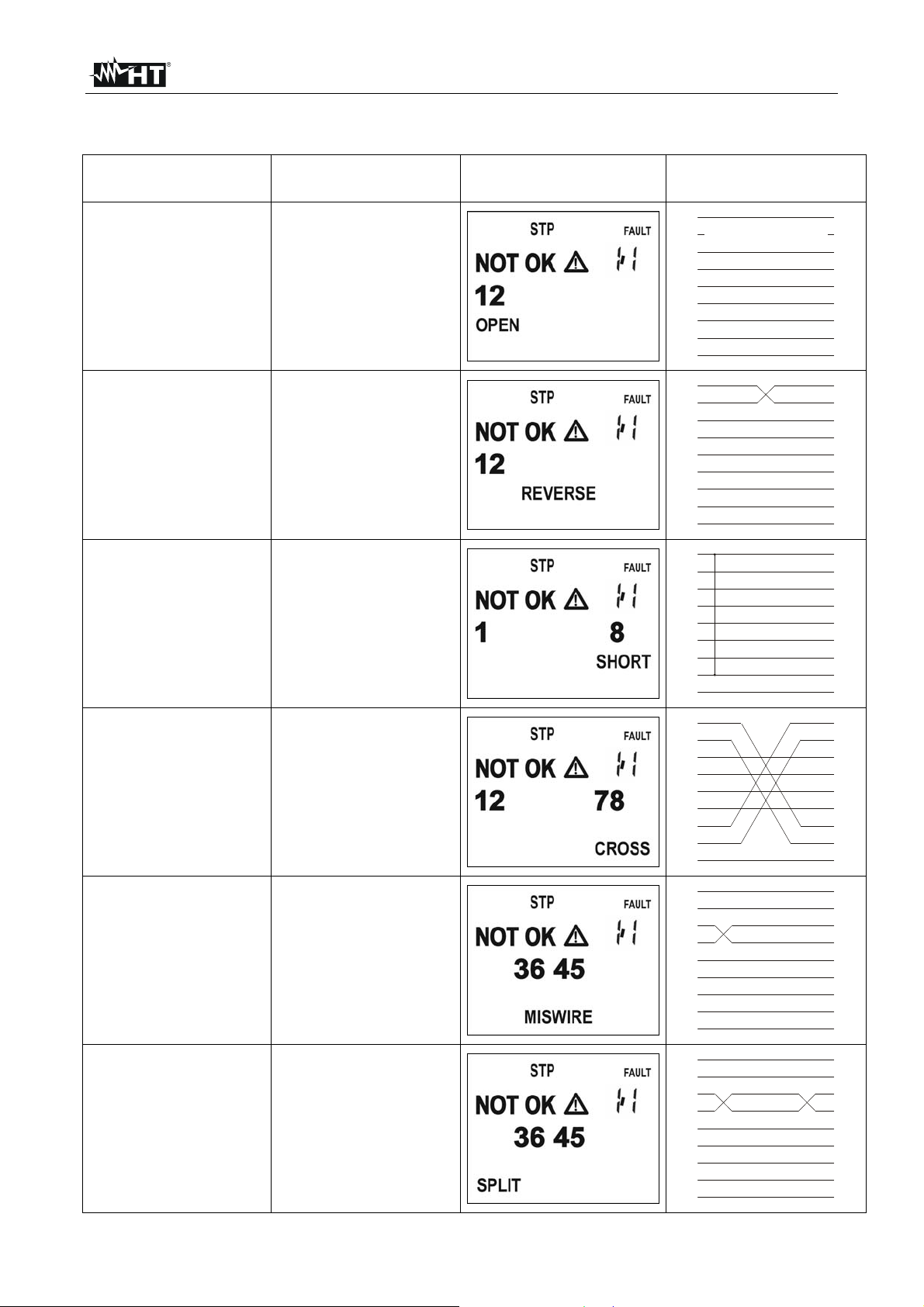
5.2. CABLING ERRORS
Cabling error Description Visualization Mapping
OPEN PAIR
REVERSED PAIR
SHORTED CABLES
One or both
conductors of the
pair are interrupted
(open)
The conductors of
the same pair are
reversed
Two conductors are
in short circuit
between each other
1
2
3
4
5
6
7
8
S
1
2
3
4
5
6
7
8
S
1
2
3
4
5
6
7
8
S
1
2
3
4
5
6
7
8
S
1
2
3
4
5
6
7
8
S
1
2
3
4
5
6
7
8
S
TRANSPOSED
(CROSSED) PAIRS
MISWIRE
SPLIT PAIRS
Two pairs are
crossed
Generic cabling
error, such as for
example two
conductors belonging
to different pairs are
exchanged
The pin to pin
correspondence is
hold, but physically
the conductors of two
pairs are crossed
1
2
3
4
5
6
7
8
S
1
2
3
4
5
6
7
8
S
1
2
3
4
5
6
7
8
S
1
2
3
4
5
6
7
8
S
1
2
3
4
5
6
7
8
S
1
2
3
4
5
6
7
8
S
EN - 7
Page 9

QUICKLAN 6055
5.3. SPLIT PAIRS EXPLANATION NOTE
A LAN cable contains 8 conductors, twisted two by two thus forming 4 pairs: 1-2, 3-6, 4-5,
7-8. The error “SPLIT PAIRS” consists in the exchange of two conductors belonging to
different pairs. The pin to pin correspondence seems intact, but physically the conductors
of two couples are split. Such interaction hardly affects (or even makes impossible) the
exchange of data at high frequency/speed.
The error condition “SPLIT PAIRS” is verified only when the cable mapping is
fully correct.
Fig. 3: Description of “Split pairs” error
CAUTION
EN - 8
Page 10
QUICKLAN 6055
6. MAINTENANCE
6.1. GENERAL INFORMATIONS
1. This model is a precision instrument. Whether in use or in storage, please do not
exceed the specification requirements to avoid possible damages or dangers
2. Do not place this meter at high temperatures or humidity or expose it to direct sunlight
3. Be sure to turn off the meter after use. If you expect not to use the tester for a long
time, remove the battery in order to avoid leakages of battery liquid that would damage
the internal parts
6.2. BATTERY REPLACEMENT
When “ ” appears on the display, replace the battery.
Only skilled technicians can open the instrument and replace batteries.
Before removing batteries disconnect the test leads from any energized
circuits to avoid electrical shocks.
1. Switch off the instrument and remove the cable from the input socket.
2. Press the battery cover and push in the direction of the arrow to open.
3. Remove the battery.
4. Replace the battery with a new one of the same type (refer to § 7.2) observing the
proper polarities.
5. Replace the battery cover.
6. Use the appropriate battery disposal methods for your area.
6.3. CLEANING
To clean the instrument use a soft dry cloth. Never use a wet cloth, solvents or water.
6.4. END OF LIFE
CAUTION
CAUTION: this symbol indicates that equipment and its accessories shall be
subject to a separate collection and correct disposal.
EN - 9
Page 11
QUICKLAN 6055
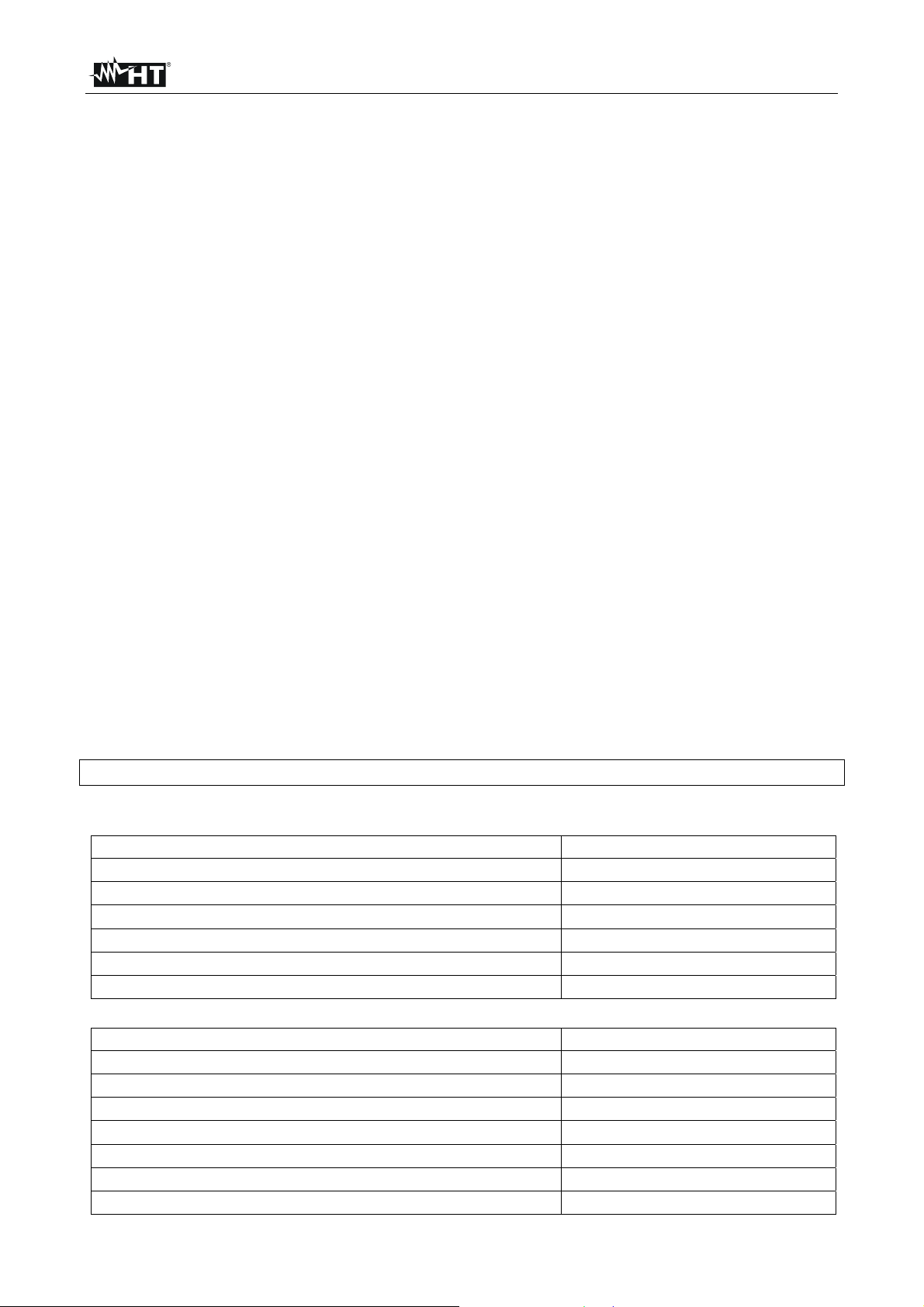
7. TECHNICAL SPECIFICATIONS
7.1. TECHNICAL SPECIFICATIONS
Connectors
LAN input connectors RJ45
Cables which can be tested
Cable type UTP, STP
Category CAT3, 5, 5E, 6, 6A, 7
Reference guideline: TIA/EIA 568B
Max height of use: 2000m
Length up to 200m
(1) To perform the test “SPLIT PAIR” the cable must be at least 1m long
7.2. GENERAL SPECIFICATIONS
Mechanical features
Dimensions (LxWxH): 128 x 67 x 39mm; (5 x 2.6 x 1.5in)
Weight (with battery): 165g; (5.8ounces)
Dimensions rem.units (LxWxH): 72 x 20 x 23mm; (2.8 x 0.8 x 0.9in)
Weight remote units: 25g; (0.9ounces)
Power supply
Battery type 1x9V type IEC 6F22
Battery life about 300 hours
Auto Power Off after 3 minutes of idleness (not disabled)
7.3. ENVIRONMENT
7.3.1. Environmental conditions
Working temperature 0 ÷ 40 °C; (32 ÷ 104°F)
Relative humidity <80%RH
Storage temperature 0 ÷ 40 °C; (32 ÷ 104°F)
Storage humidity <80%RH
This product conforms to the prescriptions of the EMC directive 2004/108/EEC
7.4. ACCESSORIES
7.4.1. Standard accessories
Description Code
Remote unit #1
Remote unit #2
Patch cables RJ45/RJ45, STP, 20cm, 3 pcs
Battery
Carrying bag
User manual
7.4.2. Optional accessories
Description Code
Remote unit #3 and cable RJ45/RJ45 STP
Remote unit #4 and cable RJ45/RJ45 STP
Remote unit #5 and cable RJ45/RJ45 STP
Remote unit #6 and cable RJ45/RJ45 STP
Remote unit #7 and cable RJ45/RJ45 STP
Remote unit #8 and cable RJ45/RJ45 STP
Remote units #3 - #8 + 6 cables RJ45/RJ45 STP
(1)
REM1
REM2
YAAMS0000000
B80
REM3
REM4
REM5
REM6
REM7
REM8
REM38
EN - 10
Page 12

QUICKLAN 6055
8. SERVICE
8.1. WARRANTY CONDITIONS
This instrument is guaranteed for one year against material or production defects, in
accordance with our general sales conditions. During the warranty period the manufacturer
reserves the right to decide either to repair or replace the product.
Should you need for any reason to return back the instrument for repair or replacement
take prior agreements with the local distributor from whom you bought it.
Do not forget to enclose a report describing the reasons for returning (detected
fault).
Use only original packaging. Any damage occurred in transit due to non original packaging
will be charged anyhow to the customer.
The warranty doesn’t apply to:
Accessories and batteries (not covered by warranty).
Repairs made necessary by improper use (including adaptation to particular
applications not foreseen in the instructions manual) or improper combination with
incompatible accessories or equipment.
Repairs made necessary by improper shipping material causing damages in transit.
Repa irs made necessary by previous attempts for repair carried out by non skilled or
unauthorized personnel.
Instruments for whatever reason modified by the customer himself without explicit
authorization of our Technical Dept.
The contents of this manual may not be reproduced in any form whatsoever without the
manufacturer’s authorization.
Our products are patented and our logotypes registered. We reserve the right to
modify specifications and prices in view of technological improvements or
developments which might be necessary.
8.2. SERVICE
Shouldn’t the instrument work properly, before contacting your distributor make sure that
batteries are correctly installed and working, check the test leads and replace them if
necessary. Should the instrument still operate improperly check that the operation
procedure is correct and conforms to the instructions given in this manual.
If the instrument is to be returned to the after-sales service or to a dealer transportation
costs are on the customer’s behalf. Shipment shall be however agreed upon. A report
must always be enclosed to a rejected product stating the reasons of its return. To ship the
instrument use only the original packaging material; any damage that may be due to nooriginal packing shall be charged to the customer.
EN - 11
 Loading...