

Page 1
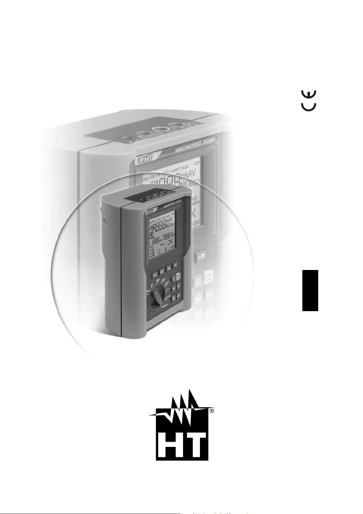
User manual
MACROTEST 5035
© Copyright HT ITALIA 2011 Release EN 1.07 - 27/07/2011
Page 2
MACROTEST 5035
Table of contents:
1. SAFETY PRECAUTIONS AND PROCEDURES ........................................................................ 3
1.1. Preliminary instructions ........................................................................................................... 3
1.2. During use ............................................................................................................................... 4
1.3. After use .................................................................................................................................. 4
1.4. Measuring (overvoltage) categories definitions ....................................................................... 4
2. GENERAL DESCRIPTION ......................................................................................................... 5
2.1. Features .................................................................................................................................. 5
2.2. Instrument description ............................................................................................................. 6
3. PREPARATION FOR USE ......................................................................................................... 7
3.1. Initial check .............................................................................................................................. 7
3.2. Power supply ........................................................................................................................... 7
3.3. Calibration ............................................................................................................................... 7
3.4. Storage .................................................................................................................................... 7
3.5. How to set measurement unit .................................................................................................. 8
4. DESCRIPTION OF THE ROTARY SWITCH FUNCTIONS ........................................................ 9
4.1. LOWΩ: Continuity test of earth protective and equalizing potential conductors ...................... 9
4.1.1. Mode "CAL" ............................................................................................................................... 10
4.1.2. Procedure to cancel calibration parameters and cal symbol ..................................................... 11
4.1.3. Procedure "AUTO", "R+TIMER", "R-TIMER" ............................................................................ 12
4.1.3.1. Mode "AUTO" ............................................................................................................................. 13
4.1.3.2. Mode "R+TIMER" or “R-TIMER" ................................................................................................ 13
4.1.4. Anomalous cases during "AUTO", "R+TIMER", "R-TIMER" tests ............................................. 13
4.2. MΩ: Insulation resistance with test voltage of 50V, 100V, 250V, 500V or 1000V ............ 15
4.2.1. Procedure to measure insulation resistance in any modes ....................................................... 15
4.2.1.1. Mode "MAN" ............................................................................................................................... 16
4.2.1.2. Mode "TIMER" ............................................................................................................................ 17
4.2.2. Special cases which may occur during the tests "MAN", "AUTO", "TIMER" ............................. 18
4.3. RCD RCD : Tests on RCDS type A or AC .......................................................... 19
4.3.1. Measurement procedure for RCD test valid for all the working modes ..................................... 21
4.3.1.1. Mode "MAN x½" ......................................................................................................................... 22
4.3.1.2. Mode "MAN x1, x2, x5" ............................................................................................................... 23
4.3.1.3. Mode "AUTO" ............................................................................................................................. 23
4.3.1.4. Mode "RAMP " ....................................................................................................................... 24
4.3.1.5. Mode "Ut" .................................................................................................................................... 25
4.3.2. Tripping times for the general and selective RCDs ................................................................... 25
4.3.3. Anomalous cases which may occur during the RCD tests in any working mode ..................... 26
4.4. LOOP : Line/Loop impedance measurement and prospective short circuit current ......... 30
4.4.1. High resolution Impedance measurement (0.1mΩ) .................................................................. 30
4.4.2. Mode "P-N" ................................................................................................................................ 31
4.4.3. Mode "P-P" ................................................................................................................................ 32
4.4.4. Mode "P-PE" .............................................................................................................................. 33
4.4.5. Mode " " ................................................................................................................................ 35
4.4.6. Anomalous cases which may occur during LOOP tests in any working mode .......................... 36
4.4.7. Anomalous cases which may occur during phase sequence tests ........................................... 39
4.5. R
a15mA
4.5.1. Anomalous cases which may occur during R
4.6. EARTH ρ: Earth resistance and resistivity measurements .................................................... 45
4.6.1. Measurement procedure for "2P" test mode ............................................................................. 46
4.6.1.1. Earth resistance measurement from a socket ............................................................................ 48
4.6.2. Measurement procedure for "3P" test mode ............................................................................. 49
4.6.3. Measurement procedure for "ρ" test mode ................................................................................ 51
4.6.4. Anomalous cases which may occur during EARTH ρ tests ...................................................... 53
5. OPERATIONS WITH MEMORY ............................................................................................... 55
5.1. Saving measurements ........................................................................................................... 55
5.2. Recall measurements ............................................................................................................ 56
5.3. Clear memory ........................................................................................................................ 57
6. RESET OF THE INSTRUMENT AND DEFAULT PARAMETERS ............................................ 58
: Global earth resistance measurement ................................................................. 41
A15mA
tests...................................................... 43
EN - 1
Page 3

MACROTEST 5035
6.1. Reset procedure .................................................................................................................... 58
6.2. Default parameters ................................................................................................................ 58
7. INSTRUMENT CONNECTION TO A PC .................................................................................. 59
8. MAINTENANCE ........................................................................................................................ 60
8.1. General .................................................................................................................................. 60
8.2. Battery replacement .............................................................................................................. 60
8.3. Cleaning ................................................................................................................................ 60
8.4. End of life .............................................................................................................................. 60
9. TECHNICAL SPECIFICATIONS ............................................................................................... 61
9.1. Technical features ................................................................................................................. 61
9.1.1. Safety standards ........................................................................................................................ 63
9.1.2. General specifications ............................................................................................................... 63
9.2. Environment .......................................................................................................................... 64
9.2.1. Environmental working conditions ............................................................................................. 64
9.3. Accessories ........................................................................................................................... 64
10. SERVICE .................................................................................................................................. 65
10.1. Warranty conditions ............................................................................................................... 65
10.2. Service .................................................................................................................................. 65
11. PRACTICAL REPORTS FOR ELECTRICAL TESTS ............................................................... 66
11.1. LOWΩ: Continuity measurement of protective conductors .................................................... 66
11.2. Insulation resistance measurement ....................................................................................... 67
11.3. Check of the circuit separation .............................................................................................. 70
11.4. Working test of RCDS (RCD, RCD/DC, RCD S, RCD/DC S) ................................................ 72
11.5. RCD tripping time test ........................................................................................................... 73
11.6. Short circuit fault impedance (ZPN, ZPP) ................................................................................. 74
11.7. Fault loop impedance measurement (phase – earth) ............................................................ 74
11.8. Earth resistance measurement in TT systems....................................................................... 75
11.9. Earth resistance measuremenT, 3-wire and 2-wire methods ................................................ 76
11.10. Earth resistivity measurement ............................................................................................... 77
EN - 2
Page 4
MACROTEST 5035
1. SAFETY PRECAUTIONS AND PROCEDURES
This apparatus conforms with safety standards IEC/EN61557 and IEC/EN61010-1 relating
to electronic measuring instruments.
Strictly keep to the following instructions before and during measurements:
• For your own safety as well as that of the apparatus you are recommended
to follow the procedures described in this instruction manual and carefully
read all the notes preceded by the symbol
• Do not take measurements in wet environments
• Do not effect measurements in environments with explosive gas, fuels or
dust
• Keep you insulated from the object under test waiting for measuring
• Avoid any contact with exposed metal parts, ends of test leads not in use,
circuits, etc
• Do not effect any measurement in case of unusual conditions of the
instrument such as deformation, breakage, leakage of substances,
absence of display reading etc
• Pay careful attention when measuring voltages exceeding 25V in particular
places (building yards, swimming pools, ..) and 50V in ordinary places
The following symbols are used on the meter and in this manual:
because of the risk of electric shock
Caution: refer to the instructions reported on this manual; improper use may
damage the apparatus or its components.
AC voltage or current
CAUTION
Double insulation
1.1. PRELIMINARY INSTRUCTIONS
• This instrument has been designed for use in environm ents with a pollution
degree 2
• It can be used for tests on electrical installations with over voltage category
III up to 265V (to Earth)
• You are recommended to comply with the standard safety regulations
aimed at protecting you against dangerous currents and protecting the
instrument against improper use
• Only the leads supplied with the instrument guarantee compliance with the
safety standards. They must be in good conditions and must be replaced, if
necessary, with identical models
• Do not perform measurements on circuits exceeding the specified voltage
limits
• Do not effect any measurement under environmental conditions beyond the
limits specified in this manual
• Check that batteries have been placed correctly
• Before connecting test leads to the circuit under test, check that rotary
switch position is correct
• Check that LCD and rotary switch indicate the same function
CAUTION
EN - 3
Page 5
MACROTEST 5035
1.2. DURING USE
Carefully read the following recommendations and instructions:
CAUTION
• No compliance with the Warnings and/or Instructions may damage the
apparatus and/or its components or injure the operator
• Before selecting any function disconnect the test leads from the circuit
under test
• When the instrument is connected to the tested circuit never touch any
test lead which is not being used
• Avoid to effect resistance measurements in the presence of external
voltages; even though the instrument is protected a too high voltage may
cause malfunctions
• If the symbol is displayed during use interrupt testing and replace
batteries following the procedure described under paragraph Errore.
L'origine riferimento non è stata trovata.. The instrument is capable of
keeping the data stored even though batteries are not installed
1.3. AFTER USE
• When the measurements are completed disconnect the test leads from the circuit
under test and after that switch OFF the instrument
• Remove batteries when the apparatus remains unused for long periods
1.4. MEASURING (OVERVOLTAGE) CATEGORIES DEFINITIONS
The norm IEC/EN61010-1: Safety requirements for electrical equipment for measurement,
control and laboratory use, Part 1: General requirements, defines what measuring
category, usually called overvoltage category, is. On paragraph 6.7.4: Measuring circuits, it
says:
(OMISSIS)
circuits are divided into the following measurement categories:
• Measurement category IV is for measurements performed at the source of the low-
voltage installation.
Examples are electricity meters and measurements on primary overcurrent protection
devices and ripple control units.
• Measurement category III is for measurements performed in the building installation.
Examples are measurements on distribution boards, circuit breakers, wiring, including
cables, bus-bars, junction boxes, switches, socket-outlets in the fixed installation, and
equipment for industrial use and some other equipment, for example, stationary motors
with permanent connection to fixed installation
• Measurement category II is for measurements performed on circuits directly
connected to the low voltage installation.
Examples are measurements on household appliances, portable tools and similar
equipment.
• Measurement category I is for measurements performed on circuits not directly
connected to MAINS.
Examples are measurements on circuits not derived from MAINS, and specially
protected (internal) MAINS-derived circuits. In the latter case, transient stresses are
variable; for that reason, the norm requires that the transient withstand capability of the
equipment is made known to the user.
EN - 4
Page 6

MACROTEST 5035
2. GENERAL DESCRIPTION
Dear Customer, we thank you for your patronage. The instrument you have just purchased
will grant you accurate and reliable measurements provided that it is used according to the
present manual’s instructions.
The instrument was designed to grant the user the utmost safety conditions thanks to a
new concept assuring double insulation and over voltage category III.
2.1. FEATURES
LOWΩ: Continuity test of earth, protective and equalizing potential conductors with
test current higher than 200mA and open circuit voltage ranging from 4V
to 24V.
MΩ: Measurement of insulation resistance with DC test voltage 50V, 100V,
250V, 500V or 1000V.
RCD : Measurement on common and/or selective RCDs AC type ( ) of
the following parameters:
Tripping time.
Tripping current.
Contact voltage (Ut).
Overall earth resistance (Ra).
Under this mode the instrument can measure the overall earth
resistance without causing RCD tripping.
RCD : Measurement on common and/or selective RCDs A type ( ) of
the following parameters:
Tripping time.
Tripping current.
Contact voltage (Ut).
Overall earth resistance (Ra).
Under this mode the instrument can measure the overall earth
resistance without causing RCD tripping.
LOOP
: Measurement of line and fault loop impedance with calculation of
prospective short circuit current. Indication of phase rotation
sequence.
R
a15mA
: Measurement of fault loop impedance between earth and phase
conductors with current of 15mA and calculation of prospective short
circuit current.
EARTH ρ: Measurement of earth resistance and earth resistivity.
EN - 5
Page 7
MACROTEST 5035
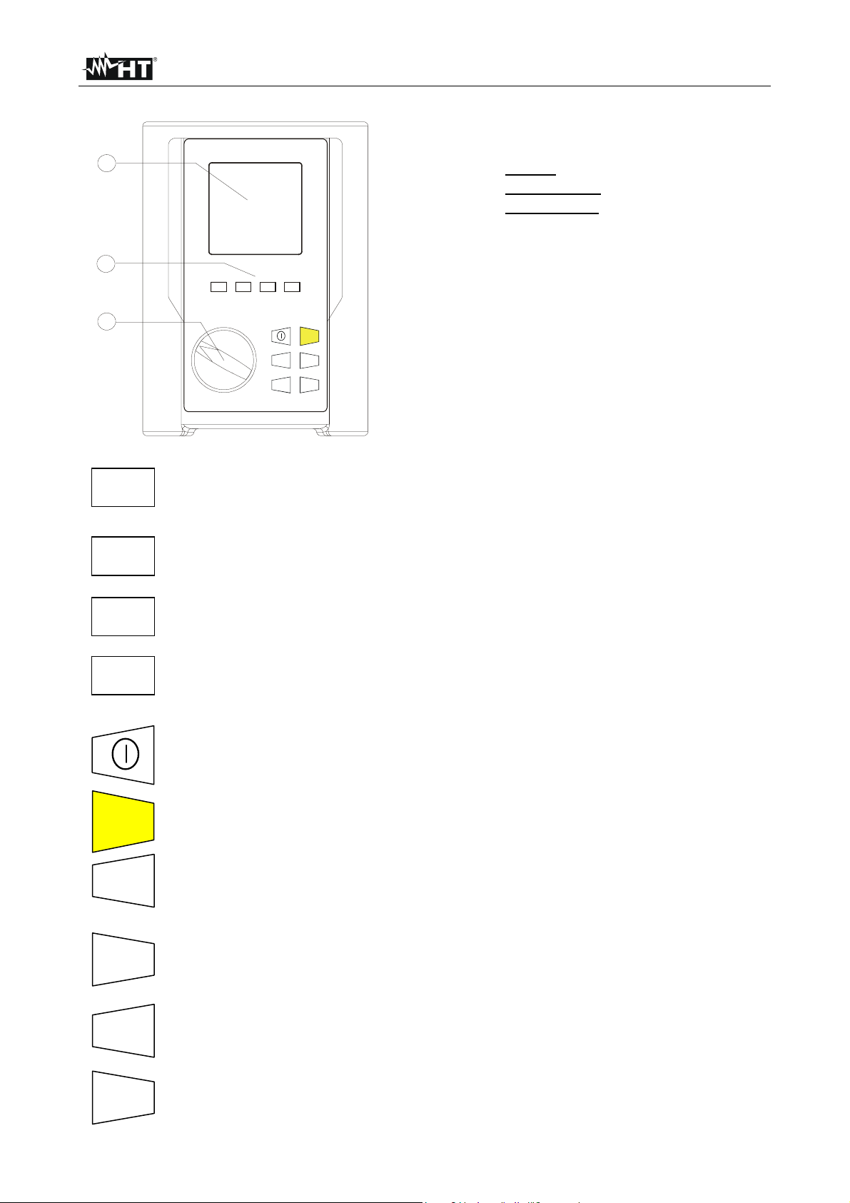
2.2. INSTRUMENT DESCRIPTION
LEGEND:
1
1. Display
2. Function keys
3. Rotary switch
2
∆
Un/I
n
FUNC
S UL
DIST
3
FUNC
Un/I∆n
DIST
S▲s
UL▼
START
STOP
DISP
CLR
RCL
ESC
SAVE
START
STOP
DISP
CLR
RCL
SAVE
ESC
FUNCTION key to select one measuring mode.
U
DIST key for selection of rated voltage, differential current or
n/I∆n
distance depending on which measurement is selected.
S▲key for selection of RCD type (Common or Selective) or to increase
the test duration interval or to scroll the results of the stored tests.
UL▼ key for selection of contact voltage limit or to decrease the test
duration interval or to scroll the results of the stored tests.
ON/OFF key. Keep it pressed some seconds for switching off the
instrument.
START/STOP key to start or to stop tests.
DISPLAY key to scroll the single and multiple tests (Ex: RCD AUTO)
which have been effected and stored.
CLEAR key to cancel the stored tests.
RECALL/ESCAPE key to recall the stored tests (RCL) and leave the
selected function or mode (ESC).
SAVE key to save tests.
EN - 6
Page 8

MACROTEST 5035
3. PREPARATION FOR USE
3.1. INITIAL CHECK
This instrument has been checked mechanically and electrically prior to shipment.
Any care has been taken to ensure that the instrument reaches you under safe conditions.
You are recommended, however, to carry our a rapid check to detect any possible
damage which might have been caused during transport. Should this be the case,
immediately contact HT Italia.
Check also that the packaging contains all the parts listed under paragraph 9.3. In case of
discrepancies contact the dealer.
In case you have to send the instrument back please follow the instructions reported in
paragraph 10.
3.2. POWER SUPPLY
The instrument is supplied by six batteries model 1.5V – LR6 – AA – AM3 – MN 1500 not
included in the package.
To replace batteries follow the instructions reported in paragraph 8.2.
When batteries are low the symbol is displayed. To replace batteries follow the
instructions indicated in paragraph 8.2
3.3. CALIBRATION
The instrument fulfils the technical specifications listed in this manual. The performance of
the specifications are guaranteed for one year.
3.4. STORAGE
In order to grant the accuracy of the measurements, after a period of storage in extreme
environmental conditions, wait for the time necessary so that the apparatus is back to
normal measuring conditions (see environmental specifications listed in paragraph 9.2.1).
EN - 7
Page 9
MACROTEST 5035
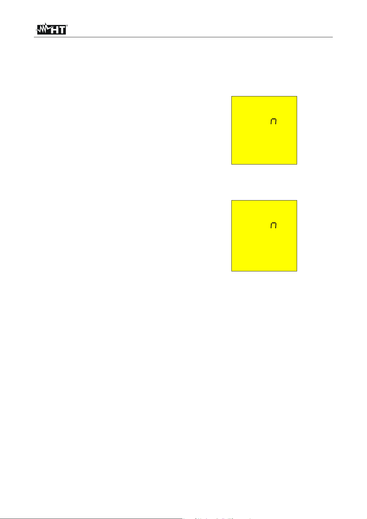
3.5. HOW TO SET MEASUREMENT UNIT
Is possible to set the distance measurement unit (in earth resistivity) following this
procedure:
1. While pushing FUNC button turn the switch on any position.
2.
The instrument will display the following
screen.
le m
3. Choose the desired distance measurement unit between meter and feet that change by
pushing S▲ and UL▼ keys (appear m and ft).
4.
Push SAVE key confirming the choice.
The instrument will display the following
screen.
le m
Push ESC key leaving this menu without
confirming any change.
OK
EN - 8
Page 10
MACROTEST 5035
4. DESCRIPTION OF THE ROTARY SWITCH FUNCTIONS
4.1. LOWΩ: CONTINUITY TEST OF EARTH PROTECTIVE AND EQUALIZING
POTENTIAL CONDUCTORS
The measurement is effected with a test current higher than 200mA and open circuit
voltage ranging from 4 to 24V DC according to EN 61557-2 and VDE 0413 part 4.
Before carrying out the continuity test make sure that there is no voltage at the
ends of the conductor under test.
Turn the switch on LOWΩ position.
Switch on the instrument.
FUNC
The key FUNC permits to select one of the following measuring modes
(which can be shown cyclically when pressing the key):
Mode AUTO (the instrument carries out two measurements with reversed
polarity R+ and R-, and displays their average value R
recommended for the continuity test.
Mode R + TIMER (measurement with positive polarity and possibility of
setting the duration time of the test). In this case the operator can set a
measuring time long enough to permit him to move the protective
conductors while the instrument is carrying out the test so detecting any
bad connection.
Mode R - TIMER (measurement with negative polarity and possibility of
setting the duration time of the test). In this case the operator can set a
measuring time long enough to permit him to move the protective
conductors while the instrument is carrying out the test so detecting any
bad connection.
Mode CAL (compensation of the resistance of the cables used for the
measurement).
NOTE: If the resistance is lower than 5Ω (including the resistance of the calibration) the
continuity test is effected by the instrument with a current higher than 200mA. If
the resistance is higher than 5Ω the continuity test is effected by the instrument
with a decreasing current.
CAUTION
). This mode is
avg
EN - 9
Page 11
MACROTEST 5035
p
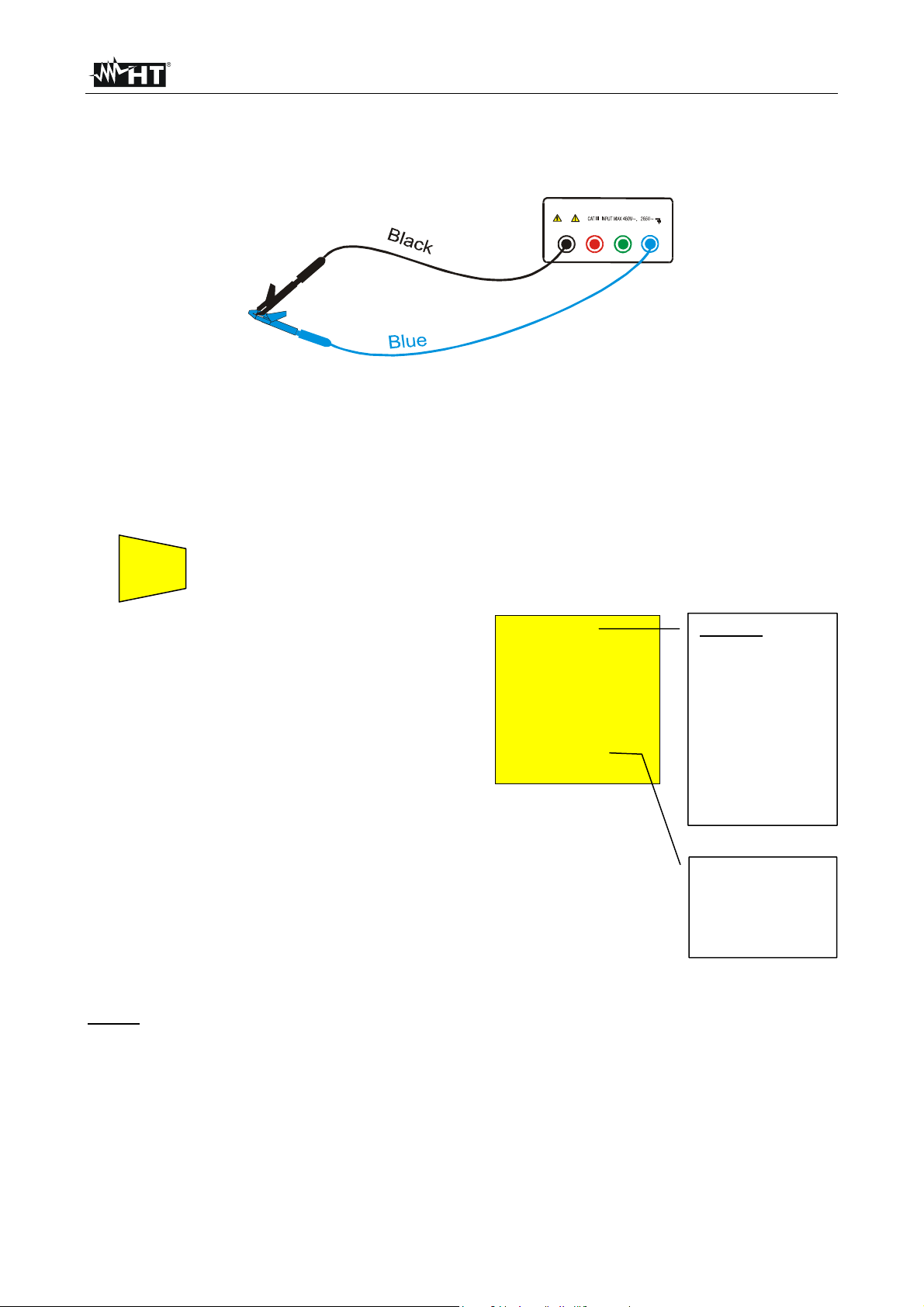
4.1.1. Mode "CAL"
1. Select mode CAL by means of the FUNC key.
2. Connect the black and blue cables to the instrument input terminals B1 and B4
respectively:
B2 B3
B1
B4
Connection of instrument terminals during calibration procedure.
3. If the cables supplied with the instrument are not long enough for the measurement you can
extend the blue cable.
4. Connect the crocodiles to the cable terminals.
5. Short-circuit the measuring cable ends making sure that the conductive parts of the
crocodiles make a good contact to each other (see previous picture).
START
6. Press the START/STOP key. The instrument carries out the calibration.
STOP
At the end of the test
the result is stored and
used as OFFSET (that
is to say that it is
subtracted from any
continuity test carried
out) for all the
subsequent
measurements until a
CAL LOWΩ
0.00 Ω
203 mA
Message CAL:
means that the
instrument was
calibrated; this
symbol remains
on the display
for any further
measurement
even though the
unit is switched
off and on again.
new calibration is
carried out.
This screen is displayed for only 2 seconds
then the instrument emits a double sound
signal (indicating that the calibration is
completed) and displays the default screen
relative to the LOWΩ test under AUTO mode.
Current supplied
by the instrument
during the
calibration
rocedure.
NOTE: The instrument effects the calibration of cables with resistance lower of 5Ω.
EN - 10
Page 12
MACROTEST 5035
CABLES USED FOR THE TEST Before each measurement always make sure that
the calibration is referred to the cables in use.
During a continuity test, if the resistance value free
of calibration (that is the resistance value less the
calibration offset value) is negative, the symbols
o as well as blinking CAL are displayed
(according to 5th screen paragraph 4.1.4).
Probably the calibration stored in the instrument
memory is referred to cables other than those in
use, therefore a new calibration is to be effected.
The display of “Measuring” means that the instrument is measuring. During
this phase never disconnect test leads.
4.1.2. Procedure to cancel calibration parameters and cal symbol
To cancel calibration parameters (and the
symbol CAL) it is necessary to effect a
calibration procedure with a resistance of
test leads higher than 5Ω (for example
with disconnected test leads). When a
cancellation is effected the screen nearby
is displayed first, followed by the screen
below:
The screen nearby is displayed for 2
seconds, after which the instrument emits a
long sound signal and then displays the
default screen relative to the LOWΩ test
under AUTO mode without the symbol CAL.
CAUTION
LOWΩ
o> 5 Ω
cal
Measuring
LOWΩ
cal
es
Message >5Ω:
means that the
instrument
detected a
resistance higher
than 5Ω
therefore it will
proceed with
Reset procedure.
Message rES:
means that the
instrument
effected
cancellation
(RESET) of the
calibration
parameters
EN - 11
Page 13
MACROTEST 5035
4.1.3. Procedure "AUTO", "R+TIMER", "R-TIMER"
1. Select the desired mode by means of the FUNC key.
2. Connect the black and blue cables to the instrument input terminals B1 and B4
respectively.
B2 B3
B1
B4
Connection of the instrument terminals during LOWΩ test.
3. If the cables supplied with the instrument are not long enough for the measurement you can
extend the black cable.
4. Connect two crocodiles to the cable terminals.
5. Short-circuit the measuring cable ends making sure that the conductive parts of the
crocodiles make a good contact to each other. Press the START/STOP key. If the
instrument displays a resistance value other than 0.00 repeat the instrument
calibration (see paragraph 4.1.1).
6. Connect the instrument terminals to the ends of the conductor on which the continuity test is
to be carried out (see previous picture).
7. If the mode "R+TIMER" or "R-TIMER" was selected use the following keys to select
the duration time of the test:
S▲
press this key to increase the duration time of the test (Tmax=15 seconds).
UL▼t
press this key to decrease the duration time of the test (Tmin=3 seconds).
START
8. Press the START/STOP key. The instrument effects the measurement.
STOP
In R+/R- Timer mode press START/STOP key again if the test is to be stopped.
CAUTION
The display of “Measuring” means that the instrument is measuring. During
this phase never disconnect test leads.
EN - 12
Page 14
MACROTEST 5035
T
g
Ω
g
4.1.3.1. Mode "AUTO"
At the end of the test, if the average
resistance value Ravg results to be
lower than 5Ω the instrument emits a
double sound signal indicating the
positive outcome of the test and
displays one screen similar to the
screen alongside.
SAVE
4.1.3.2. Mode "R+TIMER" or “R-TIMER"
If during the test a resistance value
R+Timer or R–Timer lower than 5Ω
was detected, the instrument (after the
set time has elapsed) emits a double
sound signal indicating the positive
outcome of the test displays one screen
similar to the screen alongside.
The symbols R+ or R- are displayed.
SAVE
4.1.4. Anomalous cases during "AUTO", "R+TIMER", "R-TIMER" tests
In case a value of Ravg or R+ or R-
higher than or equal to 5Ω but lower
than 99.9Ω was detected, at the end of
the test the instrument emits a long
sound signal and displays one screen
similar to the screen alongside.
ATTENTION: value of R
In AUTO mode, if a Ravg or R+ or R-
higher than 99.9Ω was detected, at
the end of the test the instrument emits
a long sound signal and displays the
screen alongside.
ATTENTION: value of R
hi
SAVING: The test can be stored pressing the SAVE key twice
(according to paragraph 5.1).
SAVING: The test can be stored pressing the SAVE key twice
(according to paragraph 5.1).
hi
her than 5
or R+ or R- is too
avg
h.
CAL LOWΩ
1.07 Ω
219 mA
AUTO
CAL LOWΩ
1.08 Ω
219 mA 5 s
R+
R-
IMER
CAL LOWΩ
o 5.75 Ω
216 mA 5 s
AUTO
CAL LOWΩ
o> 99.9 Ω
- - - mA
AUTO
Average
resistance value
Ravg.
Average test
current value
Iavg.
Duration time of
the test.
Value of the test
current I+ or I-.
Only in case the
mode R+TIMER
or R-TIMER was
selected.
AUTO mode.
99.9Ω is the
maximum value
which can be
measured in the
LOWΩ AUTO or
R+ or R-mode.
EN - 13
Page 15
MACROTEST 5035
A
In case the mode R+TIMER or RTIMER was selected and a R+ or R-
higher than 99.9Ω was detected, the
instrument emits an intermittent
sound signal during the test, a long
sound signal at the end of the test
and displays the screen alongside.
CAL LOWΩ
o> 99.9 Ω
- - - mA 4 s
R+
TIMER
99.9Ω is the
maximum value.
ATTENTION:
value of R+ or Ris too high.
In case that:
R
MEASURED-RCALIBRATION
< 0Ω the
instrument displays the screen
alongside.
CAL LOWΩ
o 0.00 Ω
Blinking CAL.
219 mA
ATTENTION: R
MEASURED-RCALIBRATION
< 0
UTO
AUTO mode.
SAVE
SAVING: The tests can be stored pressing the SAVE key twice
(according to paragraph 5.1).
If the terminal voltage is higher than
10V, the instrument does not carry out
the test and displays the screen
alongside for 5 seconds after which, the
instrument displays the screen relative
to the precedent selected test mode
LOWΩ under AUTO mode.
CAL LOWΩ
o 13V
VOL AG
ATTENTION: the
test was not
effected because
of voltage at the
terminal ends.
SAVE
THIS RESULT CANNOT BE SAVED.
EN - 14
Page 16
MACROTEST 5035
4.2. MΩ: INSULATION RESISTANCE WITH TEST VOLTAGE OF 50V, 100V,
The measurement is effected according to EN 61557-2 and VDE 0413 part 1.
250V, 500V OR 1000V
CAUTION
Before effecting the insulation test make sure that the circuit under test is not
energized and all the relative loads are disconnected.
Turn the switch on MΩ position.
Switch on the instrument.
FUNC
The key FUNC permits to select one of the following measuring modes
(which can be shown cyclically when pressing the key):
Mode MAN (minimum test time of 10 seconds or set by the pressing
duration on the START/STOP key). Recommended test.
Mode TIMER (test duration depending on the selected interval (from 10
to 999 seconds). This test can be effected in case a minimum measuring
time is required.
4.2.1. Procedure to measure insulation resistance in any modes
1. Select the desired mode by means of the FUNC key.
2. Connect the black and blue cables to the instrument input terminals B1 and B4
respectively.
P
M
B2 B3 B4B1
B2 B3 B4B1
Insulation between phase and earth in an electrical
installation using untied cables.
Insulation between phase and earth in an
electrical installation using the shuko cable.
3. If the cables supplied with the instrument are not long enough for the measurement you can
extend the blue cable.
4. Connect the instrument terminals to the object which is to be submitted to the insulation
test after disconnecting the circuit under test and all the relative loads (see
previous picture).
Un/I∆n
5. By means of U
DIST
to be carried out (see table). The values to be selected are 50, 100,
select the test voltage suitable for the type of test
n/I∆n
250, 500, 1000V DC
EN - 15
Page 17
MACROTEST 5035
Standard Brief description Test voltage Maximum limit value
Systems SELV or PELV
CEI 64-8/6
CEI 64-8/4
EN60439 Electrical panel boards 230/400V 500VDC
EN60204 Electrical equipment of machines 500VDC
Systems up to 500V (Civil installations)
Systems over 500V
Floor and wall insulation in civil installa tions
Floor and wall insulation in systems over 500V
250VDC
500VDC
1000VDC
500VDC
1000VDC
> 0.250MΩ
> 0.500MΩ
> 1.0MΩ
> 50kΩ (if V<500V)
> 100kΩ (if V>500V)
> 230kΩ
> 1MΩ
Test voltage values and the relative maximum limit values for the most common kinds of test.
CAUTION
If “Measuring” is displayed the instrument is effecting the measurement.
During this phase do not disconnect the test leads as the circuit under test
may remain charged at a dangerous voltage due to the parasite capacities of
the installation. Independently of the working mode selected the instrument
throws a resistance in the output terminals at the end of each test to
discharge the parasite capacities of the circuit.
4.2.1.1. Mode "MAN"
START
6. Press the START/STOP key.
STOP
The instrument effects the test lasting:
Minimum 6 seconds in case the key is pressed and released within 5 seconds.
Until the key is released for all the other cases.
At the end of the test, in case the
resistance value R
to be lower than R
detected results
ISO
(depending on
MAX
the selected voltage see following table)
and the test is effected at the
selected rated voltage value, the
instrument emits a double sound
signal indicating the positive
outcome of the test displays one
screen similar to the screen alongside.
R
ISO
1.00 MΩ
500 V 20 s
MAN
Rated voltage value
selected for the test.
R
insulation
ISO
resistance value
Test duration.
In this case the
START/STOP
key has been
pressed for 20
seconds.
Manual mode.
.
The values of measured resistance of isolation always must be confronted with the
normative limits (see table) for being able to assert if the system is to norm.
SAVE
SAVING: The test can be stored pressing the SAVE key twice
(according to paragraph 5.1).
EN - 16
Page 18
MACROTEST 5035
Ω
Ω
Ω
Ω
Ω
4.2.1.2. Mode "TIMER"
6. Use the following keys to set the duration time of the test:
S▲
Press this key to increase the duration time of the test (Tmax=999 seconds).
UL▼
Press this key to decrease the duration time of the test (Tmin=10 seconds).
START
7. Press the START/STOP key.
STOP
The instrument effects the measurement ending when the set time has elapsed.
999 seconds → Maximum value of the test duration.
10 seconds → Minimum value of the test duration.
Note: Pressing the START/STOP key again the test gets immediately interrupted.
At the end of the test, in case the
resistance value R
to be lower than R
detected results
ISO
(depending on
MAX
the selected voltage see following table)
and the test is effected at the selected
rated voltage value, the instrument
emits a double sound signal indicating
the positive outcome of the test
R
ISO
2.07 MΩ
500 V 20 s
TIMER
Insulation
resistance value
R
ISO.
Duration of the
set test.
Timer mode.
displays one screen similar to the screen
alongside.
Rated voltage value selected for the Timer test.
The values of measured resistance of isolation always must be confronted with the
normative limits for being able to assert if the system is to norm.
SAVE
SAVING: The test can be stored pressing the SAVE key twice
(according to paragraph 5.1).
Note: The maximum resistance value R
which can be measured in mode MΩ
MAX
depends on the rated voltage selected for the test. In particular:
Rated voltage selected
for the test
50VDC
100VDC
250VDC
500VDC
1000VDC
R
= Maximum resistance
MAX
value
99.9M
199.9M
499M
999M
1999M
Maximum resistance values measurable under MΩ mode depending on the rated voltage selected.
EN - 17
Page 19
MACROTEST 5035
p
4.2.2. Special cases which may occur during the tests "MAN", "AUTO", "TIMER"
In case a value of R
R
was detected (depending on the
MAX
selected voltage see following Note
table, the instrument emits a double
sound signal at the end of the test
indicating the positive outcome of the
test and displays one screen similar to
the screen alongside.
Maximum resistance value which can be
measured (999Ω is displayed if a rated voltage of
500V was selected see table).
In case a test is effected at a voltage
lower than the set rated voltage, at
the end of the test the instrument emits
a long sound signal and displays one
screen similar to the screen alongside.
ATTENTION: the test of resistance R
effected at a voltage value lower than the set
rated voltage. Low insulation case. This case
occurs under low insulation conditions or in the
resence of capacity on the installation.
SAVE
If the terminal voltage is higher than
30V, the instrument does not effect the
test, displays the screen alongside for 5
seconds after which, it shows the
default screen relative to the R
under selected mode.
SAVING: The test can be stored pressing the SAVE key twice
higher than
ISO
> 999 MΩ
500 V 20 s
MAN
o0.01 MΩ
500 V 20 s
was
ISO
(according to paragraph 5.1).
test
ISO
MAN
o 33V
VOL AG
R
ISO
The symbol ">"
means that the
resistance value
R
is higher than
ISO
R
MAX
Test duration
Selected mode
MAN
R
ISO
R
ISO
Selected mode
MAN
ATTENTION: the
test was not
carried out.
Check that the
circuit is not
energised.
SAVE
THIS RESULTS CANNOT BE SAVED.
EN - 18
Page 20
MACROTEST 5035
4.3. RCD RCD : TESTS ON RCDS TYPE A OR AC
The test is effected according to EN 61557-6, EN61008, EN61009, EN60947-2 B 4.2.4
and VDE 0413 part 6.
CAUTION
The automatic check of the RCD features causes the tripping of the RCD itself.
Therefore check that there is no power or load connected downstream the
RCD under test which could be affected by the installation switching off.
Possibly disconnect all the loads connected downstream the RCD as they could
add other leakage currents to the existing ones so making the test results void.
Turn the switch on RCD (RCDS type A sensitive to pulsating
leakage current) or RCD (RCDS type AC sensitive to sine leakage
current) position.
FUNC
Switch on the instrument.
The key FUNC permits to select one of the following measuring modes
(which can be shown cyclically when pressing the key):
Mode MAN x ½ (the instrument effects the test with a leakage current
equal to half the value of the rated current set with a leakage current in
phase with the voltage or a leakage current phase shifted by 180° with
respect to the voltage).
Mode MAN x 1 (the instrument effects the test with a leakage current
equal to once the value of the rated current set with a leakage current in
phase with the voltage or a leakage current phase shifted by 180° with
respect to the voltage).
Mode MAN x 2 (the instrument effects the test with a leakage current
equal to twice the value of the rated current set with a leakage current in
phase with the voltage or a leakage current phase shifted by 180° with
respect to the voltage).
Mode MAN x 5 (the instrument effects the test with a leakage current
equal to five times the value of the rated current set with a leakage
current in phase with the voltage or a leakage current phase shifted by
180° with respect to the voltage)
Mode AUTO (the instrument effects the test automatically with a leakage
current equal to half, once, five times the value of the rated current set
with a leakage current in phase with the voltage or a leakage current
phase shifted by 180° with respect to the voltage). Recommended test.
Mode RAMP (the instrument effects the test with a ramp growing
leakage current, with a leakage current in phase with the voltage or with
a leakage current phase shifted by 180° with respect to the voltage. Use
this test to measure the tripping current)
Mode Ut (the instrument effects the test with a leakage current equal to
half the value of the selected rated current and calculates the contact
voltage as well as the R
earth resistance with a leakage current in phase
a
with the voltage or a leakage current phase shifted by 180° with respect
to the voltage).
EN - 19
Page 21

MACROTEST 5035
Note: According to standard praxis it is recommended to effect RCD test both with phase
0° and with phase 180°. Therefore the test is to be repeated for both phase valves
of test current. If the RCD under test is of a type (which means sensitive to both
AC and unidirectional pulsing leakage currents) it is advisable to effect the test
both with sine wave and unidirectional pulse current with phase 0° and 180°.
Un/I∆n
DIST
The key U
the RCD (which can be shown cyclically when pressing the key):
permits to select one of the following rated tripping currents of
n/I∆n
10mA.
30mA.
100mA.
300mA.
500mA.
S▲
The key S▲ permits to activate the test for general or selective RCDs:
if the test is effected for selective RCDs the symbol S must be
displayed.
if the test is effected for general RCDs the symbol S must be NOT
displayed.
The option for testing the selective RCDs requires an interval among the
tests of 60 seconds (30 seconds in case of tests at ½ I∆n). A timer is
displayed indicating the waiting time for the instrument to effect the test
automatically.
Example: Test on a RCD with rated current of I∆n=30mA selective
a) the instrument effects the test at ½ I∆n 0°. If the RCD passed
the test, the message “OK” is displayed and the RCD does
not trip.
b) The instrument effects the test at ½ I∆n 180°. If the RCD
passed the test, the message “OK” is displayed and the
RCD does not trip. At this stage 30 seconds elapse before
effecting next test.
c) The instrument effects the test at I∆n 0°. If the RCD passed
the test, the message “OK” is displayed and the RCD trips
and the blinking symbol “rcd” is displayed. The operator
shall switch on the RCD. Anyway after the RCD tripping at
least 60 seconds will elapse before affecting next test
d) The instrument effects the test at I∆n 180°. Follow the same
procedure as described under c)
e) The instrument effects the test at 5I∆n 0°. Follow the same
procedure as described under c).
f) The instrument effects the test at 5I∆n 180°. Follow the same
procedure as described under c). The test is completed
In case of AUTO working mode the operator shall switch the RCD on whenever the
instrument displays the blinking symbol “rcd” signaling the RCD tripping
Note: On selective RCDS it is possible to carry out the following tests ”Man ½ I∆n”, ”Man
1 I∆n”, ”Man 2 I∆n”, ”Man 5 I∆n”, “AUTO”.
EN - 20
Page 22
MACROTEST 5035
UL▼
The key UL▼ permits to select one of the following limit values for the
contact voltage (which can be shown cyclically when pressing the key):
50V (default)
25V.
CAUTION
The display of “Measuring” means that the instrument is measuring. During
this phase never disconnect test leads.
Note: ”Man 5 I∆n” and “AUTO” test modes aren’t available for RCD type A 500mA.
4.3.1. Measurement procedure for RCD test valid for all the working modes
1. Select the desired mode by means of the FUNC key.
2. Connect the 3 black, blue and green connectors of the three-terminal shuko cable or of th e
single cables to the corresponding input terminals of the instrument B1, B3, B4 (see
possible connections in the pictures below). In case of using untied cables connect the
crocodiles to the free ends of the cables.
L1
L2
L3
N
B2 B3
B1
Instrument connection for 400V + N + PE three-
phase check
L1
L2
L3
N
P
B4
B2 B3
B4B1
Instrument connection for 230V single-phase or
three-phase RCD check
L1
L2
L3
B2
Instrument connection for 400V + N (no PE) three-
phase RCD check
B4B1
B3
B2 B3 B4B1
Instrument connection for 400V + PE (no N)
three-phase RCD check
3. Connect the shuko plug to a 230V 50Hz socket or the crocodile s to the RCD terminals
of the three-phase system (see previous pictures).
EN - 21
Page 23
MACROTEST 5035
contac
t voltage
4.3.1.1. Mode "MAN x½"
START
4. Press the START/STOP key once. The instrument carries out the
STOP
test injecting a current in phase with positive half wave of the
voltage indicated on display by 0°.
Press the START/STOP key twice. The instrument carries out the
test injecting a current in phase with negative half wave of the
voltage indicated on display by 180°.
If the RCD does NOT trip the
RCD ~
or RCD
instrument emits a double sound
signal indicating the positive
outcome of the test and displays the
screen alongside.
The symbol ">" means that the RCD did not trip.
Indicates if the test was carried out with current
phase 0° or 180° with respect to the voltage.
> 999 ms
OK
Ι∆N 30mA 2 V
x1/2
MAN
0° U
Limit set for the
= 50V
L
OK: indicates that
RCD passed the
test.
Value of contact
voltage U
detected referred
to the rated value
of the RCD
current set.
t
SAVE
SAVING: The test can be stored pressing the SAVE key twice
(according to paragraph 5.1).
EN - 22
Page 24
MACROTEST 5035
4.3.1.2. Mode "MAN x1, x2, x5"
START
4. Press the START/STOP key once. The instrument carries out the
STOP
test injecting a current in phase with positive half wave of the
voltage indicated on display by 0°.
Press the START/STOP key twice. The instrument carries out the
test injecting a current in phase with negative half wave of the
voltage indicated on display by 180°.
NOTE: ”Man 5 I∆n” and “AUTO” test modes aren’t available for RCD type A 500mA.
When the RCD trips if the tripping time
RCD ~
or RCD
is within the limits reported in table, the
instrument emits a double sound
signal indicating the positive
outcome of the test and displays the
screen alongside.
OK: indicates that the RCD passed the test.
It indicates if the test was carried out with current
phase 0° or 180° with respect to the voltage.
40 ms
OK
Ι∆N 30mA 1 V
x1
MAN
0° U
Limit set for the
contact voltage.
t
= 50 V
L
RCD tripping time
Value of contact
voltage U
detected referred
to the rated value
of the RCD
current set.
t
SAVE
SAVING: The test can be stored pressing the SAVE key twice
(according to paragraph 5.1).
4.3.1.3. Mode "AUTO"
START
4. Press the START/STOP key: The instrument carries out the following
STOP
six tests with different values of rated current:
1/2I∆n at 0° (the RCD shall not trip).
1/2I∆n at 180° (the RCD shall not trip).
I∆n at 0° (the RCD trips, blinking rcd, switch it on again).
at 180° (the RCD trips, blinking rcd, switch it on again).
I
∆n
5I
at 0° (the RCD trips, blinking rcd, switch it on again).
∆n
5I∆n at 180° (the RCD trips, end of the test).
In AUTO mode for each positive result (tripping time within the limits
see table) of a single test the following are displayed:
OK test passed.
Blinking rcd switch the RCD on again (if the RCD is not switched on
again the instrument does not proceed with the test).
The test ends if all values of test tripping times fall within the limits
reported in table, or at the first value out of limits.
EN - 23
Page 25

MACROTEST 5035
NOTE: ”Man 5 I∆n” and “AUTO” test modes aren’t available for RCD type A 500mA.
At the end of the test if
RCD ~
or RCD
all six tests resulted to
be positive, the
instrument displays the
screen alongside
relative to the last
measurement effected.
OK: indicates that the RCD
passed the test.
23 ms
OK
Ι∆N 30mA 1 V
x5
AUTO 180° U
t
= 50V
L
Value of contact
voltage U
detected referred
to the rated value
of the RCD
current set.
t
5. Press the DISP key to scroll the results relative to the six tests
DISP
effected which can be shown cyclically according to the following
order: ½I∆n at 0°, ½I∆n at 180°, I∆n at 0°, I∆n at 180°, 5I∆n at 0°, 5I∆n at
180°.
SAVE
SAVING: The test can be stored pressing the SAVE key twice
(according to paragraph 5.1).
4.3.1.4. Mode "RAMP "
START
4. Press the START/STOP key once. The instrument carries out the
STOP
test injecting a current in phase with positive half wave of the
voltage indicated on display by 0°.
Press the START/STOP key once. The instrument carries out the
test injecting a current in phase with negative half wave of the
voltage indicated on display by 180°.
The instrument generates a leakage current growing step by step
for a given time interval.
At the end of the test if the RCD tripping
RCD ~
or RCD
current is ≤ I∆n (Type AC) or 1.4I∆n (Type
A with I∆n > 10mA) or 2I∆n (Type A with
I∆n ≤ 10mA), the instrument emits a
double sound signal indicating the
positive outcome of the test and
displays the screen alongside.
Value of contact voltage Ut detected referred to the
rated value of the RCD current set.
41 ms 1 V
0° U
24 mA
OK
t
= 50 V
L
RCD tripping time
OK: indicates that
the RCD passed
the test.
SAVE
SAVING: The test can be stored pressing the SAVE key twice
(according to paragraph 5.1).
EN - 24
Page 26

MACROTEST 5035
If the parameters set on the instrument are consistent with the kind of RCD under test
(and if the latter works properly) the ramp test “ ” SHALL CAUSE THE RCD TRIPPING
WITH A CURRENT LOWER THAN OR EQUAL TO THE SELECTED RATED
DIFFERENTIAL CURRENT. This test is not used to be effected to compare the RCD
tripping time at the tripping current, while the standards refer to the maximum tripping
times in case the RCD is checked with a leakage current equal to the rated current.
4.3.1.5. Mode "Ut"
START
4. Press the START/STOP key once: the instrument carries out the
STOP
test.
If the RCD does NOT trip the
RCD ~
or RCD
instrument emits a double sound
signal indicating the positive
outcome of the test and displays the
screen alongside.
Value of contact voltage Ut detected referred to the
rated value of the RCD current set.
Value of earth resistance Ra. The display of the
message "o.r." means that the instrument detected
a resistance higher than 1999Ω.
Ι∆N 30mA 49 Ω
U
0° U
1.4 V
OK
t
=50 V
L
OK: indicates that
the RCD passed
the test.
It indicates if the
test was carried
out with current
phase 0° or 180°
with respect to
the voltage.
SAVE
SAVING: The tests can be stored pressing the SAVE key twice
(according to paragraph 5.1).
4.3.2. Tripping times for the general and selective RCDs
If the parameters set on the instrument are in keeping with the type of RCD under test
(and if this works correctly) the test with leakage current I
x1, I∆N x2, I∆N x5 SHALL
∆N
cause the RCD tripping within the times set according to the following table:
RCD type
I
x 1 I
∆N
x 2 I
∆N
∆N
x 5
Description
General 0.3s 0.15s 0.04s Max tripping time in seconds
0.5s 0.20s 0.15s Max tripping time in seconds
Selective S
0.13s 0.05s 0.05s Minimum delay tripping time in
seconds
* For rated values I∆N ≤ 30mA the test current at five times is 0.25A.
For currents equal to ½
I
the RCD shall not trip in any case.
∆N
Tripping times for tests with leakage currents I
∆
x1, I
N
∆
x2, I
N
x5 and AUTO.
N
∆
EN - 25
Page 27

MACROTEST 5035
4.3.3. Anomalous cases which may occur during the RCD tests in any working
mode
Should the instrument detect that the
RCD ~
or RCD
phase and/or neutral cables are not
connected to an installation, screen
alongside is displayed when pressing
START/STOP.
Message “no VOL tAGE”: a too low voltage was
detected
o
P-N
VOL AG
Should the instrument detect a voltage
RCD ~
or RCD
between phase and neutral higher of
265V, for example in case the blue
cable is connected to an installation
phase conductor of a 400V three-phase
system, the screen alongside is
displayed.
o Hi
P-N
VOL AG
Message
“Hi VOL tAG”:
a too high voltage
was detected.
This screen is displayed when the phase
RCD ~
or RCD
conductor was reversed with respect to
the neutral one.
The instrument does not effect the test.
Reverse the shuko plug or exchange the black
cable with the blue one. Repeat the test.
o A
P-N
Message "Att":
voltage between
phase and earth
is too low.
This screen is displayed when the
RCD ~
or RCD
phase conductor was reversed with
respect to the earth one.
The instrument does not effect the test.
Reverse the phase to earth connection in the plug
or exchange the black cable with the green one.
o A
P-PE
Message "Att":
voltage between
phase and earth
is too low.
This screen is displayed when in
RCD ~
or RCD
biphase system the blue conductor was
reversed with respect to the green one.
o A
PEN
The instrument does not effect the test.
SAVE
THE PREVIOUS RESULTS CANNOT BE SAVED.
EN - 26
Page 28

MACROTEST 5035
If the instrument detects that the earth
RCD ~
or RCD
cable (green) is not connected, the
screen alongside is displayed for 5
seconds then the initial display is back.
Check the connections of PE conductor
under test.
o>1999 Ω
no PE
Message
“no PE”: the
instrument does
not detect the
protection circuit.
SAVE
THE PREVIOUS RESULT CANNOT BE SAVED.
In the tests MAN x1, x2, x5 and AUTO
RCD ~
or RCD
(during x1 and x5 tests), if the RCD
trips to separate the circuit within a time
not complying with the limits reported in
table, the instrument emits a long
sound signal at the end of the test and
displays the values alongside.
o 487 ms
Ι∆N 30mA 1 V
x1
MAN
t
0° U
= 50V
L
RCD tripping time
ATTENTION: the
tripping time is
higher than the
standard limit.
If the RCD trips within a time higher
than the instrument’s measuring limits,
the instrument emits a long sound
signal at the end of the test and
displays the values alongside.
RCD ~
o> 999 mS
Ι∆N 30mA 2 V
x1
MAN
t
0° UL= 50 V
RCD tripping
time:
> maximum
measuring time
(it depends on
type of test, see
following table).
The maximum duration depends on the test type:
Test type General RCD Selective RCD
MAN x1 test 999ms 999ms
MAN x2 test 200ms 250ms
MAN x5 test 50ms 160ms
“ ” test 300ms
SAVE
SAVING: The tests can be stored pressing the SAVE key twice
(according to paragraph 5.1).
EN - 27
Page 29

MACROTEST 5035
)
During the ramp test if the RCD trips
to separate the circuit at a tripping
current higher than I∆n (Type AC) or 1.4
I∆n (Type A with I∆n>10mA) or 2 I∆n
(Type A with I∆n≤10mA), the instrument
emits a long sound signal at the end
of the test and displays the values
alongside.
ATTENTION: the RCD tripping current is higher
than the rated value of the set differential current
=30mA was set in the example
(I
∆N
During the ramp test for general
RCDs if the RCD trips to separate the
circuit, the instrument emits a long
sound signal at the end of the test
and displays the values alongside.
Maximum current generated by the instrument
during the test for general RCDs (the value
indicated is referred to an AC type 30mA RCD, in
this case the maximum current supplied is equal to
.
SAVE
If a contact voltage U
selected limit (U
instrument interrupts the test and emits
a long sound signal at the end of the
test and displays the values
alongside.displays the screen
alongside.
Message “>50V” o “>25V”: the instrument detects
a contact voltage higher than the selected limit
(50V in this case).
SAVE
In order to store the contact voltage value Ut (out of the limits) effect the test under U
mode.
SAVING: The tests can be stored pressing the SAVE key twice
(according to paragraph 5.1).
higher than the
t
) is detected the
L
0° UL=50V
THIS RESULT CANNOT BE SAVED.
RCD ~
o 33 mA
= 50V
L
58ms 1 V
t
0° U
RCD ~
o> 300 mS
Ι∆N 42mA 2 V
t
0° UL= 50 V
RCD ~
o> 50 V
A UL
I
∆N
x5
MAN
t
or RCD
RCD tripping time
Contact voltage
U
referred to the
L
value of rated
current.
or RCD
Message "Att
UL": a too high
contact voltage
was detected.
t
EN - 28
Page 30

MACROTEST 5035
In case the instrument is unable to
generate the current because the fault
loop presents a too high resistance, the
instrument emits a long sound signal
at the end of the test and displays the
values alongside.
RCD ~
o A
Ι∆N hi ES
t
AUTO 0° UL= 50 V
Message
“HI rES”: the
instrument
detected a too
high resistance
therefore it is
unable to effect
the test.
During Ut test if the instrument detect s
RCD ~
a contact voltage Ut higher than the full
scale value, a long sound signal is
emitted at the end of the test and
displays the screen alongside
Message ">100V" or “>50V”:
the instrument detected a contact voltage higher
than the full scale. Under U
full scale is equal to 100V or 50V depending on the
value set for U
equal to 50V or 25V.
L
mode the instrument
t
o> 100 V
A UL
I
∆N
0° UL=50V
t
If the RCD trips during the preliminary
test at ½ Idn (independently from the
working mode) the instrument displays
the screen alongside until voltage
between phase and earth is detected
again then the previous selected
screen is back.
RCD ~
o c
Ι∆N - - - - - -
x1
MAN
t
0° UL=50 V
Message “rcd”:
the RCD trips too
early. Some
leakage currents
may be present in
the installation.
If the thermistores of the instrument are
RCD ~
damaged, it displays the screen
alongside.
o c
If the instrument gets overheated, tests
cannot be carried out and the message
alongside is displayed. Wait until the
initial screen is back in order to proceed
with measurements.
Message “hot”: the instrument got overheated.
SAVE
THIS RESULTS CANNOT BE SAVED.
EN - 29
RCD ~
o
Page 31

MACROTEST 5035
W
Ω
4.4. LOOP : LINE/LOOP IMPEDANCE MEASUREMENT AND
PROSPECTIVE SHORT CIRCUIT CURRENT
Turn the switch on LOOP position.
Switch on the instrument.
FUNC
The key FUNC permits to select one of the following measuring modes
(which can be shown cyclically when pressing the key):
Mode “P-N” (the instrument measures the resistance between the phase
and neutral conductors and calculates the phase to neutral prospective
short circuit current).
Mode “P-P” (the instrument measures the resistance between two phase
conductors and calculates the phase to phase prospective short circuit
current).
Mode “P-PE” (the instrument measures the resistance between the
phase and protective conductors and calculates the phase to earth
prospective short circuit current).
Mode “ ” (the instrument detects the phase sequence and measures
the three delta voltages: L1-2, L2-3, L3-1).
CAUTION
The display of “Measuring” means that the instrument is measuring. During
this phase never disconnect test leads.
4.4.1. High resolution Impedance measurement (0.1mΩ)
Macrotest5035 is connectable to an external optional accessory (IMP57) useful for high
resolution impedance measurement close to a power transformer.
The high Resolution impedance measurement is available inside the LOOP P-P, P-N, P-PE
modes by mean Un/I∆n key.
If You enable the High Resolution Impedance Measurement mode without connecting IMP57
the following screen will be displayed:
LO
o
!
LOOP
!!no
con ins
For further details regarding IMP57 use and technical characteristics please refer to IMP57
user's manual or HT web site www. htitalia.com.
EN - 30
Page 32

MACROTEST 5035
p
4.4.2. Mode "P-N"
1. Select P-N mode by means of the FUNC key.
2. If possible disconnect all low impedance loads downstream the point at which the
measurement is to be taken, as such an impedance would be in parallel with the line
impedance to be measured.
3. Connect the 3 black, blue and green connectors of the three-terminal shuko cable or of the
single cables in the corresponding input terminals of the instrument B1, B3, B4 (see
possible connections in the following pictures). When using untied cables connect the
crocodiles to the free ends of the cables.
L1
L2
L3
N
P
B2 B3
B1
B4
Instrument connection for 230V single-phase or
two-phase line impedance measurement
B2 B3
Instrument connection for line impedance
measurement in a 400V three-phase system
B4B1
4. Connect the shuko plug into a 230V 50Hz socket or the crocodiles to the conductors of
the three-phase system (see previous pictures).
START
5. Press the START/STOP key. The instrument starts the test.
STOP
At the end of the test the instrument
emits a double sound signal
indicating that the test is correctly
terminated and displays the values
alongside.
Effective value of the phase to neutral prospective
short circuit current expressed in Ampere
calculated according to the following formula.
LOOP
1.07 Ω
P-N
223 V 214 A
Value of phase to
neutral line
impedance
ex
ressed in Ω.
Phase to neutral
effective voltage
value expressed
in Volt.
CAUTION
The measurement of Phase-Neutral impedance entails the following of a
current of about 6A between the above said conductors. This may cause the
tripping of magnetothermal RCDs with nominal value lower than 10A. If
necessary effect the test upstream the RCD itself.
U
Calculation formula of prospective short circuit current:
where UN= phase to neutral voltage 127V if V
≤ 150V; 230V if 150V < V
meas
I =
CC
N
Z
PN
≤ 265V
meas
SAVE
SAVING: The tests can be stored pressing the SAVE key twice
(according to paragraph 5.1).
EN - 31
Page 33

MACROTEST 5035
p
4.4.3. Mode "P-P"
1. Select P-P mode by means of the FUNC key.
2. If possible disconnect all low impedance loads downstream the point at which the
measurement is to be taken, as such an impedance would be in parallel with the line
impedance to be measured.
3. Connect the 3 black, green and blue connectors of the single cables in the corresponding
input terminals of the instrument B1, B3, B4 (see possible connections in the following
pictures). When using untied cables connect the crocodiles to the free ends of the cables.
L1
L2
L3
N
B2
B4B1
B3
Instrument connection for measurement of phase to phase impedance
4. Connect the crocodiles to the conductors of the three-phase system (see picture).
START
5. Press the START/STOP key. The instrument starts the test.
STOP
At the end of the test the instrument
emits a double sound signal
indicating that the test is correctly
terminated and displays the values
alongside.
Effective value of the phase to phase prospective
short circuit current expressed in Ampere
calculated according to the following formula.
LOOP
1.07 Ω
P-P
383 V 374 A
Value of phase to
phase line
impedance
ressed in Ω.
ex
Phase to phase
effective voltage
value expressed
in Volt.
CAUTION
The measurement of Phase-Phase impedance entails the following of a
current of about 11.5A between the above said conductors. This may cause
the tripping of magnetothermal RCDs with nominal value lower than 10A. If
necessary effect the test upstream the RCD itself.
U
Formula for calculation of prospective short circuit current:
I =
CC
N
Z
PP
where UN= phase to phase voltage 127V if V
230V if 150V < V
400V if V
meas
meas
≤ 150V
meas
> 265V
≤ 265V
SAVE
SAVING: The tests can be stored pressing the SAVE key twice
(according to paragraph 5.1).
EN - 32
Page 34

MACROTEST 5035
4.4.4. Mode "P-PE"
1. Select P-PE mode by means of the FUNC key.
2. Connect the 3 black, blue and green connectors of the three-terminal shuko cable or of th e
single cables in the corresponding input terminals of the instrument B1, B3, B4 (see
possible connections in the following pictures). When using untied cables connect the
crocodiles to the free ends of the cables.
L1
L2
L3
N
P
B2 B3
B1
B4
Connection for loop impedance measurement in
a 230V single- or two-phase system
B2 B3
Connection for loop impedance measurement in
a 400V three-phase system with neutral
B4B1
L1
L2
L3
B2 B3 B4B1
Measurement of loop impedance in a 230 or 400V three-phase system without neutral
3. Connect the shuko plug into a 230V 50Hz socket or the crocodiles to the conductors of
the three-phase system (see previous pictures).
4. The instrument carries out the test verifyi ng that the contact voltage of the installation
masses relating to the current actually supplied by the instrument is not higher than the
limit contact voltage value. The limit contact voltage which reference is made to is that
set under one of the following functions: RCD , RCD or R
a15mA
.
Example: if you are effecting some tests in a medical room, the limit contact voltage is
equal to 25V. The operator will switch on one of the following functions: RCD ,
RCD or Ra
, and select the limit contact voltage of 25V by means of ULt. At
15mA
this stage if you turn the selector on LOOP ZS/IK under mode P-PE, the instrument will
refer to the limit of 25V during the test.
EN - 33
Page 35

MACROTEST 5035
p
START
5. Press the START/STOP key once. The instrument carries out the
STOP
test injecting a current in phase with positive half wave of the
voltage indicated on display by 0°.
Press the START/STOP key twice. The instrument carries out the
test injecting a current in phase with negative half wave of the
voltage indicated on display by 180°.
At the end of the test the instrument
emits a double sound signal
indicating that the test is correctly
terminated and displays the values
alongside.
Effective value of the phase to earth prospective
short circuit current expressed in Ampere
calculated according to the following formula.
LOOP
3.65 Ω
P-PE
221 V 63A
Value of phase to
earth fault
impedance
ex
ressed in Ω.
Phase to earth
effective voltage
value expressed
in Volt.
CAUTION
The measurement of Phase-PE impedance entails the following of a current
of about 6A between the above said conductors. This may cause the tripping
of magnetothermal RCDs with nominal current value lower. If necessary
effect the test upstream the RCD itself.
Formula for calculation of prospective short circuit current:
U
N
I =
CC
Z
PE
where U
= phase to earth voltage 127V if 100V < V
N
230V if 150V < V
meas
meas
< 150V
≤ 265V
SAVE
SAVING: The tests can be stored pressing the SAVE key twice
(according to paragraph 5.1).
EN - 34
Page 36

MACROTEST 5035
g
4.4.5. Mode " "
1. Connect the three black, red and green connectors of the untied cables in the corresponding
input terminals of the instrument B1, B2, B3 and the crocodiles to the free ends of the
cables.
L1
L2
L3
N
B2 B3
B1
B4
Instrument connection for phase sequence indication L1=black cable, L2=blue cable, L3=green cable
2. Connect the crocodiles to the three phases of the system under test. The instrument
displays the following screen (before pushing START/STOP key):
Voltage value between Phase1 and Phase2.
386 V
Voltage value between Phase3 and Phase1.
388 V 388 V
Voltage value between Phase2 and Phase3.
START
4. Press the START/STOP key to start the measurement of phase
STOP
sequence, one of the following screen will be displayed:
At the end of the test the instrument
displays the values alongside in case of
correct phase sequence, which means
the black cable is connected to the
phase1=L1, the blue cable to the
phase2=L2 and green cable to the
phase3=L3.
At the end of the test the instrument
displays the values alongside in case of
wrong phase sequence.
CAUTION
o 213
The display of “Measuring” indicates that the instrument is effecting the
measurement. During this phase do not disconnect the test leads from the
instrument.
SAVE
SAVING: The tests can be stored pressing the SAVE key twice
(according to paragraph 5.1).
123
Message "123":
means that the
phase sequence
is correct.
Message "213":
means that the
phase sequence
is wron
.
EN - 35
Page 37

MACROTEST 5035
4.4.6. Anomalous cases which may occur during LOOP tests in any working mode
Should the instrument detect that the
phase and/or neutral cables are not
connected to an installation, screen
alongside is displayed when pressing
START/STOP.
LOOP
o
P-N
Message
"no VOL tAG”: a
too low voltage
was detected.
VOL AG
This screen is displayed when system
the phase conductor was reversed with
respect to the neutral.
The instrument does not effect the test.
Reverse the shuko plug and exchange the black
cable with the blue one. Check the earth
connection. Repeat the test.
This screen is displayed when the
phase conductor was reversed with
respect to the earth.
The instrument does not effect the test.
Reverse the phase to earth connection in the plug
under test or exchange the black cable with the
green one. Repeat the test.
Should the instrument detect a voltage
between phase and neutral higher of
265V, for example in case the blue
cable is connected to an installation
phase conductor of a 400V three-phase
system, the screen alongside is
displayed.
This screen is displayed when in
biphase system the blue conductor was
reversed with respect to the green one.
LOOP
o A
P-N
LOOP
o A
P-PE
LOOP
o Hi
P-N
VOL AG
LOOP
o A
PEN
Message “Att”:
too low voltage
between phase
and earth.
Message “Att”:
too low voltage
between phase
and neutral.
Message “Hi
VOL tAG”: a too
high voltage was
The instrument does not effect the test.
SAVE
THE PREVIOUS RESULTS CANNOT BE SAVED.
EN - 36
Page 38

MACROTEST 5035
If the instrument detects that the earth
LOOP
cable (green) is not connected, the
screen alongside is displayed for 5
seconds then the initial display is back.
Check the connections of PE conductor
under test.
o>1999 Ω
no PE
Message
“no PE”: the
instrument does
not detect the
protection circuit.
If a contact voltage U
selected limit (U
higher than the
t
) is detected the
L
instrument interrupts the test and emits
a long sound signal at the end of the
test and displays the values
alongside.displays the screen
alongside.
Message ">50" o “>25V”: the instrument detects
a contact voltage higher than the selected limit
(50V in this case).
o> 50 V
0° UL=50V
LOOP
A UL
t
Message "Att
UL":
a too high
contact voltage
was detected
The instrument
can display 0° or
180°
If during the test the instrument detects
a lack of voltage the screen alongside
is displayed.
If the thermistores of the instrument are
damaged, it displays the screen
alongside.
If the instrument gets overheated it
does not permit to effect the tests and
displays the message alongside. Wait
until the instrument displays the initial
screen before proceeding with
measuring.
SAVE
THE PREVIOUS RESULTS CANNOT BE SAVED.
LOOP
o c
P-P
- - - - - -
t
LOOP
o c
LOOP
o
P-P or P-N
or P-PE
Messagge “hot”:
the instrument is
overheated.
EN - 37
Page 39
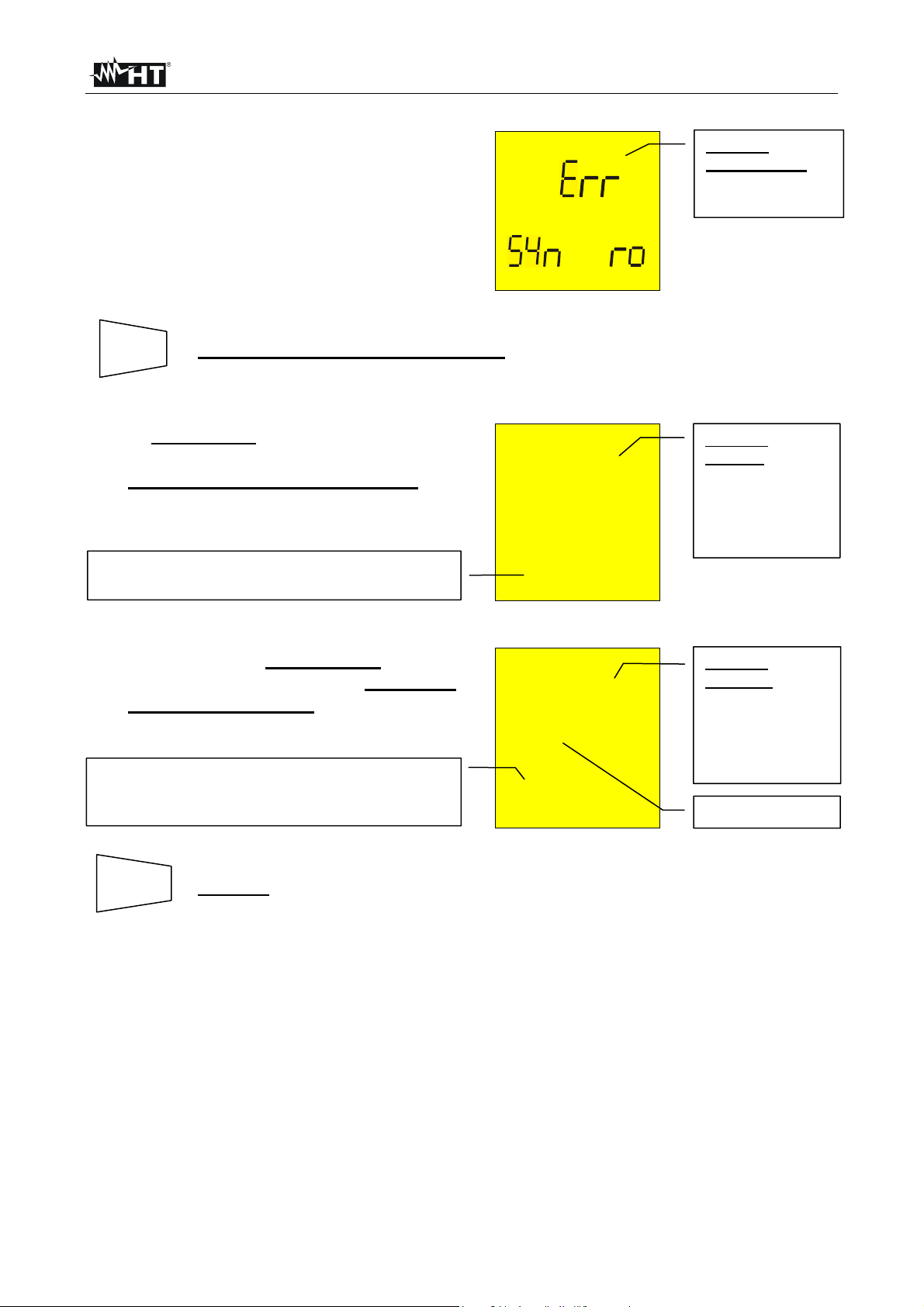
MACROTEST 5035
If the instrument finds a network
frequency out of range it does not
permit to effect the tests and displays
the message alongside.
LOOP
o
Message
“Err SYn cro”:
frequency is out
of range.
c
SAVE
THIS RESULT CANNOT BE SAVED.
If under P-PE mode the instrument
carries out the test and detects a
resistance to higher than 1999Ω, the
screen alongside is displayed.
Value of voltage existing between the instrument’s
terminals phase to earth
Under mode P-P o P-N if the
instrument detects a resistance
higher than 199.9Ω the instrument
displays the alongside screen.
Value of voltage existing between the instrument’s
terminals (phase to phase if the test is P-P, phase
to neutral if the test is P-N).
SAVE
SAVING: The tests can be stored pressing the SAVE key twice
(according to paragraph 5.1).
o>1999 Ω
218 V 1 A
o>199.9 Ω
P-N
218 V 1 A
LOOP
LOOP
Message
“>1999”: the
instrument
detects an earth
resistance higher
than 1999Ω.
Message
">199.9":
the instrument
detects a line
loop resistance
higher than
199.9Ω.
P-N or P-P
EN - 38
Page 40

MACROTEST 5035
p
4.4.7. Anomalous cases which may occur during phase sequence tests
In case that every delta voltages result
to be lower than 100V, the instrument
does not effect the test and displays
the screen alongside.
Messagge “Lo VOL tAG”: the instrument has at
least one too low voltage. The instrument does not
effect the test.
VOL AG
L
If the voltage present at B1 input too
low, when START/STOP is pressed the
instrument displays the message
alongside.
o A
Message “Att no
L1”: voltage of
phase 1 is too low
l1
If the voltage present at B2 input too
low, when START/STOP is pressed the
instrument displays the message
alongside.
o A
Message “Att no
L2”: voltage of
phase 2 is too low
If the voltage present at B3 input too
low, when START/STOP is pressed the
instrument displays the message
alongside.
If two measurement cables were
connected to the same phase
conductor, when START/STOP is
pressed the instrument displays the
message alongside.
SAVE
THE PREVIOUS RESULTS CANNOT BE SAVED.
l2
o A
l3
o ph
Message “Att no
L3”: voltage of
hase 3 is too low
Message “PH
double”: two
cables are
connected to the
same phase
conductor.
EN - 39
Page 41

MACROTEST 5035
If one cable is not connected to the
network or one phase is absent, the
instrument displays the screen
alongside
Black cable=L1 is not connected to one phase of
the installation. Voltage between phase L3 and
phase L1 is null (L3 - L1).
Black cable=L1 is not connected to one phase of
the installation. Voltage between phase L1 and
phase L2 is null (L1-L2).
If two or more cables of the instrument is
not connected, it displays screen
alongside.
0 V
0 V 388 V
Black cable= L1
is not connected
to one phase of
the installation.
Voltage between
phase L2 and
phase L3 is not
null (L2- L3).
0 V
SAVE
0 V 0 V
SAVING: The tests can be stored pressing the SAVE key twice
(according to paragraph 5.1).
EN - 40
Page 42

MACROTEST 5035
4.5. R
a15mA
: GLOBAL EARTH RESISTANCE MEASUREMENT
Turn the switch on R
a15mA
position.
Switch on the instrument.
1. Connect the three black, blue and green connectors of the shuko cable or of the untied
cables in the corresponding input terminals of the instrument B1, B3, B4 (see possible
connections in the following pictures). When using untied cables connect the crocodiles to
the free ends of the cables.
L1
L2
L3
N
P
B2 B3
B1
B4
Connection for Global Earth Resistance in a 230V
single- or two-phase system
B2 B3
Connection for Global Earth Resistance in a 400V
three-phase system with neutral
B4B1
L1
L2
L3
B2 B3 B4B1
Global Earth Resistance in a 230V or 400V three-phase system without neutral
2. Connect the shuko plug into a 230V 50Hz socket or the crocodiles to the conductors of
the three-phase system (see previous picture).
EN - 41
Page 43

MACROTEST 5035
Ω
3. The key UL▼ permits to select one of the following limit values for the
UL▼
contact voltage (which can be shown cyclically when pressing the key):
50V (default)
25V.
START
4. Press the START/STOP key. The instrument starts the test.
STOP
At the end of the test the instrument
emits a double sound signal
indicating that the test is correctly
terminated and displays the values
alongside.
Effective value of the phase to earth prospective
short circuit current expressed in Ampere
calculated according to the following formula.
Resolution is 1A.
RCD LOOP
49 Ω
P-PE
223 V 4 A
Value of Global
Earth Resistance
expressed in Ω.
Resolution is 1
Value of phase to
earth voltage
detected during
the measurement.
Resolution is 1V.
.
Note: The test permits to effect the measurement of Global Earth Resistance without
causing RCD tripping in case of RCD with rated I∆N higher than or equal to 0.03A.
Formula for the calculation of the prospective short circuit current:
U
I =
CC
N
R
A
where UN= phase to earth voltage 127V if 100V < V
230V if 150V < V
R
= global earth resistance
A
meas
meas
≤ 150V
≤ 265V
CAUTION
The display of “Measuring” indicates that the instrument is effecting the
measurement. During this phase do not disconnect the test leads from the
instrument.
SAVE
SAVING: The tests can be stored pressing the SAVE key twice
(according to paragraph 5.1).
EN - 42
Page 44

MACROTEST 5035
4.5.1. Anomalous cases which may occur during R
Should the instrument detect that the
phase and/or neutral cables are not
connected to an installation, screen
alongside is displayed when pressing
START/STOP.
Message "no": the instrument does not effect the
test because a too low voltage was detected.
o
P-N
VOL AG
Should the instrument detect a voltage
between phase and neutral higher of
265V, for example in case the blue
cable is connected to an installation
o Hi
P-N
phase conductor of a 400V three-phase
system, the screen alongside is
VOL AG
displayed.
This screen is displayed when the
RCD LOOP
phase conductor was reversed with
respect to the neutral.
o A
P-N
A15mA
RCD LOOP
tests
RCD LOOP
Message no VOL
tAG: a too low
voltage was
detected.
Message “Hi
VOL tAG”: a too
high voltage was
detected
Message "ATT":
voltage between
phase and earth
is too low.
The instrument does not effect the test. Reverse
the shuko plug or exchange the black cable with
the blue one. Repeat the test
This screen is displayed when the
phase conductor was reversed with
respect to the earth.
The instrument does not effect the test. Reverse
the phase to earth connection in the plug under
test or exchange the black cable with the green
one. Repeat the test.
This screen is displayed when in
biphase system the blue conductor was
reversed with respect to the green one.
The instrument does not effect the test.
SAVE
THE PREVIOUS RESULTS CANNOT BE SAVED.
RCD LOOP
o A
P-PE
RCD LOOP
o A
PEN
Message "Att":
voltage between
phase and
neutral is too
low.
EN - 43
Page 45

MACROTEST 5035
(
If the instrument detects that the earth
cable (green) is not connected, the
screen alongside is displayed for 5
seconds then the initial display is back.
Check the connections of PE conductor
under test.
RCD LOOP
o>1999 Ω
no PE
Message
"no PE": the
instrument does
not detect the
protection circuit.
If a contact voltage U
selected limit (U
higher than the
t
) is detected the
L
instrument interrupts the test and emits
a long sound signal at the end of the
test and displays the values
alongside.displays the screen
alongside.
Message ">50" o “>25V”:
the instrument detects a contact voltage higher
than the selected limit
50V in this case)
RCD LOOP
o> 50 V
A UL
Message
"Att UL": a too
high contact
voltage was
detected
If no power is detected during the test
RCD LOOP
the instrument displays the screen
alongside.
o c
If the thermistores of the instrument are
damaged, it displays the screen
alongside.
If the instrument gets overheated it
does not permit to effect the tests and
displays the message alongside. Wait
until the instrument displays the initial
screen before proceeding with
measuring.
SAVE
THE PREVIOUS RESULTS CANNOT BE SAVED.
- - - - - -
RCD LOOP
o c
RCD LOOP
o
Messagge “hot”:
the instrument is
overheated.
EN - 44
Page 46

MACROTEST 5035
If under P-PE mode the instrument
caries out the test and detects a global
earth resistance to higher than
1999Ω, the screen alongside is
displayed for 5 seconds then the initial
display is back.
RCD LOOP
o>1999 Ω
P-PE
Message
">1999": the
instrument
detects an earth
resistance higher
than 1999Ω.
Value of contact voltage Ut detected referred to
the carried out value of the RCD current set.
Resolution 1V.
31 V 0 A
SAVE
SAVING: The tests can be stored pressing the SAVE key twice
(according to paragraph 5.1).
4.6. EARTH ρ: EARTH RESISTANCE AND RESISTIVITY MEASUREMENTS
Turn the switch on EARTH ρ position.
Switch on the instrument.
FUNC
The key FUNC permits to select one of the following measuring modes
(which can be shown cyclically when pressing the key):
Mode “2P” (the instrument measures earth resistance between 2 points).
Mode “3P” (the instrument measures earth resistance using two auxiliary
earth rods).
Mode “ρ“ (the instrument measures earth resistivity).
The resistance is measured with a 4-cables voltamperometric method, so the value
measured is not depending on the utilized cables. For this reason this method doesn’t
need any cables calibration.
If the cables weren’t long enough, lengthen them or utilize cables longer than the standard
ones. Pay attention to always lengthen each cable separate from each one other.
EN - 45
Page 47

MACROTEST 5035
play
4.6.1. Measurement procedure for "2P" test mode
1. Select "2P" earth measurement mode by means of the F1 key.
2. Connect the B lac k , Red, Green and Blue cables to the corresponding input terminals of the
instrument B1, B2, B3, B4 (see possible connections in the following picture).
3. Connect the black, and green cables to the earth plant and red and blue cables to the
auxiliary rod.
B2 B3
B4B1
2 points earth resistance measurement
START
4. Press the START/STOP key. The instrument starts the test.
STOP
At the end of the test the instrument
displays the values alongside.
EARTH
Measured
resistance value
0.96 Ω
Average value of earth resistance calculated over
the number of test dis
ed.
2P 0.93 Ω
CAUTION
Mode “2P”.
The display of “Measuring” means that the instrument is measuring. During
this phase never disconnect test leads.
SAVE
SAVING: The tests can be stored pressing the SAVE key twice
(according to paragraph 5.1).
Note: If START/STOP key was kept pressed, the instrument takes more consecutive
tests.
5. When a new value is acquired the instrument emits a short sound and calculates the
new average value.
6. Press DISP key to show how many measurements are in average value
DISP
calculation and the measuring mode.
7. Press CLR key if you want to cancel the medium value of the resistance
CLR
and the no. of measurements which are included in the calculation.
EN - 46
Page 48

MACROTEST 5035
When the environmental conditions preclude the “3P” measurement mode, as for example
in the city center, In TT plants is possible to measure the earth resistance with the
simplified “2P” method that gives an higher value than the “3P” mode does.
An auxiliary rod is necessary, it must have an unimportant earth resistance and must be
independent by the earth plant under test.
In the picture is shown a water tube as auxiliary rod, but it could be replaced by any
metallic object fixed to the ground.
Example: if the operator takes three consecutive measurements, the instrument displays
1st measurement:
main display = measured resistance value (Ex: 0.90Ω)
secondary display on the left-hand side = 001 (no. of measurements = 1
means that 1 earth measurement has been taken)
secondary display = average of the measurements taken (in case just one
measurement has been taken the medium value is equal to the measured
value, in this case 0.90Ω)
2nd measurement:
main display = measured resistance value (Ex: 0.96Ω)
secondary display = average of the measurements taken ((Val1+Val2)/no.
of measurements = (0.90+0.96)/2 = 0.93Ω)
3rd measurement:
main display = measured resistance value (Ex: 0.93Ω)
secondary display = average of the measurements taken ((Val1+Val2)/no.
of measurements = (0.90+0.96+0.93)/3 = 0.93Ω)
Note: Any test with result over 1999Ω is not inserted in the calculation of medium value.
Example: 1st measurement:
main display: 1,07Ω
secondary display: 1,07Ω
2nd measurement
main display: 4,15Ω
secondary display: 2,61Ω
rd
measurement (not inserted in the medium value)
3
main display: >1999Ω
secondary display: 2,61Ω
EN - 47
Page 49

MACROTEST 5035
4.6.1.1. Earth resistance measurement from a socket
On TT installations it’s possible to take an earth measurement with a simplified method,
which gives an excess value (therefore safer), using the NEUTRAL of the national Energy
Board taken directly from a socket as an auxiliary rod; if also the earth connection is
available, naturally the measurement can be taken on the socket directly, between
NEUTRAL and EARTH.
Although this test is not provided for by CEI 64.8 at present, it gives a value which many 3wires comparison tests proved to be revealing for earth resistance.
B2 B3
B4B1
Earth measurement with simplified method on panel board
WARNING
• If you want to take the measurement using the neutral and the earth of a
normal socket, you may happen to connect to the phase. In this case the
display will show the voltage, the symbol (wrong inserting) and won’t
take any measurement even if START/STOP is pressed
• The display of “Measuring” means that the instrument is measuring.
During this phase never disconnect test leads
EN - 48
Page 50

MACROTEST 5035
the number of test displayed
4.6.2. Measurement procedure for "3P" test mode
The measurement is taken according to what prescribed for CEI 64.8, IEC 781, VDE 0413,
EN61557-5.
1. Select "3P" earth measurement mode by means of the F1 key.
2. Connect the B lac k , Red, Green and Blue cables to the corresponding input terminals of the
instrument B1, B2, B3, B4 (see possible connections in the following picture).
3. Connect the black, and green cables to the earth plant and red and blue cables to the
auxiliary rods.
B2
B4B1
B3
3 points earth resistance measurement
Measuring small earth plants, current probe must be positioned a distance from the earth
equipment outline corresponding to five times the diagonal of the area of the earth
equipment under test, measuring big earth plants this distance could be reduced up to one
time the diagonal.
START
4. Press the START/STOP key. The instrument starts the test.
STOP
At the end of the test the instrument
displays the values alongside.
EARTH
Measured
resistance value
0.96 Ω
Average value of earth resistance calculated over
.
2P 0.93 Ω
CAUTION
Mode “2P”.
SAVE
The display of “Measuring” means that the instrument is measuring. During
this phase never disconnect test leads.
SAVING: The tests can be stored pressing the SAVE key twice
(according to paragraph 5.1).
EN - 49
Page 51

MACROTEST 5035
Note: If START/STOP key was kept pressed, the instrument takes more consecutive
tests.
5. When a new value is acquired the instrument emits a short sound and calculates the
new average value.
6. Press DISP key to show how many measurements are in average value
DISP
calculation and the measuring mode.
CLR
7. Press CLR key if you want to cancel the medium value of the resistance
and the no. of measurements which are included in the calculation.
Example: if the operator takes three consecutive measurements, the instrument displays
1st measurement:
main display = measured resistance value (Ex: 0.90Ω)
secondary display on the left-hand side = 001 (no. of measurements = 1
means that 1 earth measurement has been taken)
secondary display = average of the measurements taken (in case just one
measurement has been taken the medium value is equal to the measured
value, in this case 0.90Ω)
2nd measurement:
main display = measured resistance value (Ex: 0.96Ω)
secondary display = average of the measurements taken ((Val1+Val2)/no.
of measurements = (0.90+0.96)/2 = 0.93Ω)
3rd measurement:
main display = measured resistance value (Ex: 0.93Ω)
secondary display = average of the measurements taken ((Val1+Val2)/no.
of measurements = (0.90+0.96+0.93)/3 = 0.93Ω)
Note: Any test with result over 1999Ω is not inserted in the calculation of medium value.
Example: 1st measurement:
main display: 1,07Ω
secondary display: 1,07Ω
2nd measurement
main display: 4,15Ω
secondary display: 2,61Ω
3rd measurement (not inserted in the medium value)
main display: >1999Ω
secondary display: 2,61Ω
EN - 50
Page 52

MACROTEST 5035
4.6.3. Measurement procedure for "ρ" test mode
The earth resistivity is a very useful parameter, its value could help the designer to
correctly size the earth rods in an earth plant.
The measurement is taken according to what prescribed for CEI 64.8, IEC 781, VDE 0413,
EN61557-5
1. Select "ρ" earth measurement mode by means of the F1 key.
2. Connect the B lac k , Red, Green and Blue cables to the corresponding input terminals of the
instrument B1, B2, B3, B4 (see possible connections in the following picture).
3. Connect the cables to the auxiliary rods (see connections in the following picture).
B2 B3 B4B1
a
a
a
a
Earth resistivity measurement
4. To select the distance DIST between the rods. This parameter can take
Un/I∆n
DIST
the following values (expressed in meters): 1, 2, 3, 4, 5, 6, 7, 8, 9, 10.
At the end of the test the instrument
-ρ
displays the values alongside.
5 m
SE LE
Distance between the rods set value.
UL▼
5. Press UL▼ and S▲s keys to select the distance value.
S▲
6. Press ESC key to leave this menu confirming the settings.
7. Press the START/STOP key. The instrument starts the test.
RCL
ESC
START
STOP
EN - 51
Page 53

MACROTEST 5035
At the end of the test the instrument
ρ
displays the values alongside.
Earth resistivity value
36.5 Ωm
2 0.93 Ω
CAUTION
The display of “Measuring” means that the instrument is measuring. During
this phase never disconnect test leads.
SAVE
SAVING: The tests can be stored pressing the SAVE key twice
(according to paragraph 5.1).
Note: If START/STOP key was kept pressed, the instrument takes more consecutive
tests.
8. When a new value is acquired the instrument emits a short sound and calculates the
new average value.
9. Press DISP key to show how many measurements are in average value
DISP
calculation and the measuring mode.
10. Press CLR key if you want to cancel the medium value of the resistance
CLR
and the no. of measurements which are included in the calculation.
Note: Any test with result over 1999Ω is not inserted in the calculation of medium value.
Example: 1
st
measurement (D=1):
main display: 6,6Ωm
secondary display: 6,6Ωm
2nd measurement (D=1):
main display: 4,15Ω
secondary display: 2,61Ω
3rd measurement (not inserted in the medium value)
main display: >1999Ω
secondary display: 2,61Ω
EN - 52
Page 54

MACROTEST 5035
4.6.4. Anomalous cases which may occur during EARTH ρ tests
If the voltmetric circuit (red and green
cables) is interrupted, when pressing
START/STOP the instrument doesn’t
manage to read the minimum voltage,
therefore a screen similar to the one
beside appears. Make sure that the
terminals are connected correctly and
that the voltmetric rod (red conductor)
has not been driven into a gravely or
scarcely conductive ground. If
necessary, pour water around the rod.
If the amperometric circuit is
interrupted, when pressing
START/STOP the instrument doesn’t
manage to read the minimum current,
therefore a screen similar to the one
beside appears. Make sure that the
terminals are connected correctly and
that the amperometric rod (blue
conductor) has not been driven into a
gravely or scarcely conductive ground.
If necessary, pour water around the
rod.
In case both the amperometric circuit
and the voltmetric circuit are
interrupted, when pressing
START/STOP the instrument doesn’t
manage to read the minimum current
nor the minimum voltage, therefore a
screen similar to the one beside
appears. Make sure that the terminals
are connected correctly and that the
amperometric and voltmetric rods (blue
and red conductors) has not been
driven into a gravely or scarcely
conductive ground. If necessary, pour
water around the rod.
SAVE
THE PREVIOUS RESULTS CANNOT BE SAVED.
o - - -
P - - -
o - - -
- - - c
o - - -
P c
rP indicates an
high resistance
value.
rC indicates an
high resistance
value.
rC and rP indicate
a high resistance
value both for the
voltmetric circuit
and for the
amperometric
circuit.
EN - 53
Page 55

MACROTEST 5035
If the instrument measures an
interfering voltage higher than 30V
on the amperometric circuit, it
doesn’t perform the test and a screen
similar to the one beside appears.
Voltage value on the amperometric circuit
o 31 V
VOL AG
SAVE
THE PREVIOUS RESULT CANNOT BE SAVED.
If the resistance measured is higher
than the full scale of the instrument,
when pressing START/STOP the
instrument performs the test and a
o >1999 Ω
1999Ω is the full
scale of the
instrument.
screen similar to the one beside
appears.
- - - - - -
If the resistivity measurement is higher
than the following value
1999x6.28x(distance between the rods
selected), when pressing
START/STOP the instrument performs
the test and a screen similar to the one
beside appears.
o> 1999 Ω
- - - - - -
1999Ω is the full
scale of the
instrument.
SAVE
SAVING: The tests can be stored pressing the SAVE key twice
(according to paragraph 5.1).
EN - 54
Page 56
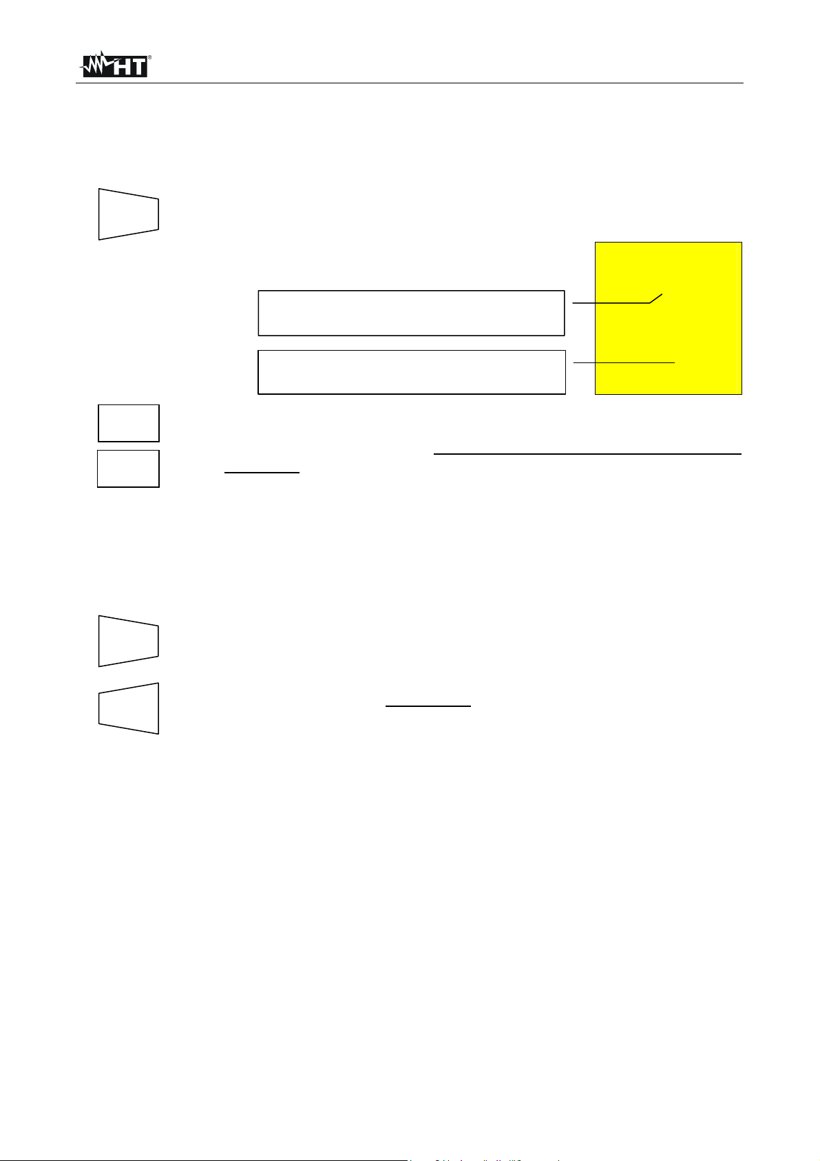
MACROTEST 5035
5. OPERATIONS WITH MEMORY
5.1. SAVING MEASUREMENTS
If the results relative to the tests effected are to be stored you can proceed as follows:
SAVE
1. Press the SAVE key once.
If the memory of the instrument is not
empty it displays the screen alongside.
Number of the memory location in which the
measurement results will be stored.
MEM
3
Value of the parameter PLA related to the
Pla 02
measurement to be saved.
UL▼
2. Use the UL▼, S▲s keys to incr ease or diminish the value of the PLA
S▲
parameter to be related to the measurement which is to be saved. This
parameter helps the operator to classify the tests effected.
Example: if the tests are to be carried out in a building, the operator
can associate the measurements effected in a room with a
given value of the parameter PLA. In this way different
value of the parameter PLA will correspond to different
rooms.
SAVE
3. Press the SAVE key again, the instrument emits two sound signals
confirming that the test results have been stored.
RCL
ESC
Press RCL/ESC key at any time to leave the memory menu and go
back to the measurement selected.
EN - 55
Page 57

MACROTEST 5035
5.2. RECALL MEASUREMENTS
If you want to recall the stored test results proceed as follows:
RCL
1. Press the RCL/ESC key.
ESC
If the memory of the instrument is not
MEM
empty it displays the screen alongside.
Number of the memory location in which the
measurement results were stored.
3
Pla 02
Value of the parameter PLA related to the
saved measurement
UL▼
2. Use the UL▼, S▲s keys to select the memory location number to be
S▲s
displayed.
3. Press the DISP key to display the test result related to the selected
DISP
memory location. If a RCD AUTO mode was selected, press DISP key
another time to scroll all the data stored.
UL▼t
4. Use the UL▼, S▲s keys again if you want to display again the numbers
S▲ s
of memory locations.
RCL
ESC
Press RCL/ESC key at any time to leave the memory menu and go back
to the measurement selected.
EN - 56
Page 58

MACROTEST 5035
5.3. CLEAR MEMORY
If you want to cancel the stored tests results proceed as follows:
RCL
1. Press the RCL/ESC key. The instrument displays a screen like the
ESC
following:
Number of the memory location in which the
measurement results were stored.
MEM
3
Value of the parameter PLA related to the
saved measurement.
UL▼t
Pla 02
2. Use the UL▼, S▲ keys to select the number of the memory location.
S▲s
ATTENTION: the instrument will cancel all the results stored from the memory location
selected to the last one full.
3. Press the DISP key to display the test result related to the memory
DISP
location selected. In case that a few results were stored in the memory
location (Ex: RCD test under AUTO mode) it is necessary to press DISP
more than once to display them
CLR
4. Press CLR once. The blinking symbol "clr" is displayed. Now you face
two possibilities:
Last location with data stored number.
MEM
C i
The instrument cancels the memory cells from
n.2 to n.8, where n.2 is the one selected by
the operator while n.8 is the last test saved in
the instrument.
02 08
CLR
Press CLR again if the tests selected are to be cancelled
starting from the one selected down to the last one saved.
RCL
ESC
Press RCL/ESC to nullify the clearing phase. The blinking
symbol "clr" disappears.
RCL
ESC
Press RCL/ESC key at any time to leave the memory menu and go back
to the measurement selected.
EN - 57
Page 59

MACROTEST 5035
6. RESET OF THE INSTRUMENT AND DEFAULT PARAMETERS
BEFORE OF A RESET PROCEDURE DOWNLOAD THE STORED TESTS ON A PC
6.1. RESET PROCEDURE
1. Press at the same time the keys DISP, CLR, RCL and then ignite the instrument.
2.
The screen nearby is displayed
for 5 seconds, after which the
instrument emits a sound signal
and then displays the screen
relative to the function selected
with the rotary switch.
ATTENTION: the reset procedure will cancel all the stored tests and it will set the
default parameters in the instrument.
6.2. DEFAULT PARAMETERS
After a RESET the default parameters set on the instrument are:
es
Function Parameter RESET default parameter
Mode AUTO
LOWΩ
Calibration Offset
Mode R+/R- TIMER
TIMER is set at 1s
0
Mode MAN
MΩ
RCD type
A/AC
LOOP ZS/IK
EARTH ρ
Memory
Test voltage 500V
Mode TIMER TIMER is set at 60s
Mode x1
Test differential current 30mA
Contact voltage limit 50V
Mode P-N
Parameter DIST DIST = 1
Parameter PLA P = 1
Memory state 0
EN - 58
Page 60

MACROTEST 5035
7. INSTRUMENT CONNECTION TO A PC
The connection between PC and instrument is realized through the serial port and optical
serial cable, provided with the software package.
Before effecting the connection it is necessary to select the COM port used for the
transmission. To set this parameter start the software and look up the help on line.
ATTENTION: The selected port shall NOT be shared by other devices or applications
(example mouse, modem, etc.)..
To transfer the stored data from the instrument to the PC keep to the following procedure:
1. Turn the switch on position RS232.
2. The item "Ser" appear at display as shown in herewith picture.
Then proceed according to the software instruction manual to transfer the
measurements effected.
The communication between
instrument and PC occurs.
se
Note: The right download speed is: 9600 baud (see software instruction manual).
EN - 59
Page 61

MACROTEST 5035
8. MAINTENANCE
8.1. GENERAL
1. The tester you have purchased is a precision instrument. Strictly follow the instructions
for use and storage reported in this manual to avoid any possible damage or danger
during use.
2. Do not use this tester under unfavorable conditions of high temperature or humidity. Do
not expose to direct sunlight.
3. Be sure to turn off the tester after use. If the instrument is not to be used for a long
period you are recommended to remove batteries to avoid acid leakage which may
damage the internal circuits of the instrument.
8.2. BATTERY REPLACEMENT
When the symbol is displayed batteries are to be replaced.
Only skilled technicians can perform this operation. Before replacing batteries
make sure that all test leads have been disconnected from input terminals. The
instrument is capable of keeping the data stored even though batteries are
not installed
1. Switch OFF the instrument.
2. Remove all the test leads from the input terminals.
3. Unscrew the fixing screws from the battery compartment cover and remove it.
4. Remove all batteries replacing them with 6 new ones of the same type (1.5V – LR6 –
AA – AM3 – MN 1500) respecting the polarity signs.
5. Fix the screws on the battery compartment cover. Then put the holster on.
8.3. CLEANING
Use a soft dry cloth to clean the instrument. Never use wet cloths, solvents, water, etc.
8.4. END OF LIFE
CAUTION
CAUTION: this symbol indicates that equipment and its accessories shall be
subject to a separate collection and correct disposal.
EN - 60
Page 62

MACROTEST 5035
9. TECHNICAL SPECIFICATIONS
9.1. TECHNICAL FEATURES
Accuracy is indicated as [% of reading + number of digits]. It refers to the atmospheric
conditions listed in paragraph 9.2.1.
Continuity (LOWΩ)
Test mode
AUTO, R+TIMER, R-TIMER
Test current >200mA DC up to 5Ω (include the resistance of the calibration)
Test current resolution 1mA
Open circuit Test Voltage 6V < V
Measuring range (Ω) Resolution (Ω)
0,01 – 19,99 0,01
20,0 – 99,9 0,1
< 12V
0
Insulation resistance (R
Test voltage (V)
50
100
250
500
1000
ISO
)
Measuring range (Ω) Resolution (Ω)
0,01 - 19,99 0,01
20,0 - 49,9 0,1
50,0 - 99,9 0,1
0,01 - 19,99 0,01
20,0 - 99,9 0,1
100,0 - 199,9 0,1
0,01 - 19,99 0,01
20,0 - 199,9 0,1
200 - 249 1
250 - 499 1
0,01 - 19,99 0,01
20,0 - 199,9 0,1
200 - 499 1
500 - 999 1
0,01 - 19,99 0,01
20,0 - 199,9 0,1
200 - 999 1
1000 - 1999 1
Accuracy
±(2% rdg + 2 dgt)
Accuracy
±(2% rdg + 2 dgt)
±(5% rdg + 2 dgt)
±(2% rdg + 2 dgt)
±(5% rdg + 2 dgt)
±(2% rdg + 2 dgt)
±(5% rdg + 2 dgt)
±(2% rdg + 2 dgt)
±(5% rdg + 2 dgt)
±(2% rdg + 2 dgt)
±(5% rdg + 2 dgt)
Automatic selection of the measuring range
Open circuit voltage Rated voltage test –0% +10%
Short circuit current <6,0mA with 500V set
Rated measuring current >2,2mA with 500V on 230kΩ
1mA a 1KΩ x V
(≠ 500 V)
NOM
RCD tripping tests (RCD
or RCD )
RCD type AC, A General and Selective
Range of phase to earth voltage 100 ÷ 265V 50Hz + 0.5 Hz
Rated tripping currents (I∆N) 10mA, 30mA, 100mA, 300mA, 500mA
0 ÷ 2U
)
t
t lim
0,1 -0%, +(5% rdg + 3 dgt)
Contact voltage (U
Measuring range (V) Resolution (V) Accuracy
Ut lim (UL): 25V o 50V
EN - 61
Page 63

MACROTEST 5035
∆
÷
∆
÷
∆
∆
÷
∆
÷
∆
Tripping time (t∆N)
Measuring range (ms) Resolution (ms) Accuracy
½ I∆N, I∆N 1÷999
1÷200 general
2 I
∆N
1÷250 selective
RCD (*) 1÷50 general
5 I
∆N
1
±(2% rdg + 2 dgt)
1÷160 selective
(*) ”Man 5 I∆n” and “AUTO” test modes aren’t available for RCD type A 500mA
- Earth resistance R
Measuring range (Ω) Resolution (Ω)
Test current 0.5 I∆N set in Ut test mode
15mA in Ra 15mA test
without RCD tripping
A
1 ÷ 1999
Accuracy
1 -0%, +(5% rdg + 3 dgt)
Tripping current for RCD type A and AC
General RCD with I∆N ≤ 10mA
RCD type
AC
A
Measuring range I
(0,5
1,4) I
(0,5
2,4) I
N
N
(mA)
N
Resolution (mA) Accuracy
0,1 I
-0%, +10% I∆N
∆N
General RCD with I∆N > 10mA
RCD type
AC
A
Measuring range I
(0,5
1,4) I
(0,5
2) I
(mA)
N
N
N
AC voltage
Measuring range (V) Resolution (V) Accuracy
0 ÷ 460
Frequency
Measuring range (Hz) Resolution (Hz) Accuracy
47,0 ÷ 63,6
Line impedance (phase to phase or phase to neutral)
Measuring range (Ω) Resolution (Ω)
0,01 ÷ 19,99
20,0 ÷ 199,9
Max peak test current 127V 3,65A
230V 6,64A
400V 11,5A
Phase to phase test voltage 100 ÷ 460V 50Hz ±0,5Hz
Phase to neutral test voltage 100 ÷ 265V 50Hz ±0,5Hz
Fault loop impedance
Measuring range (Ω) Resolution (Ω)
0,01 ÷ 19,99
20,0 ÷ 199,9
200 ÷ 1999
Max peak test current 127V 3,65A
230V 6,64A
Phase to earth test voltage 100 ÷ 265V 5 0Hz ±0,5Hz
Resolution (mA) Accuracy
0,1 I
-0%, +10% I∆N
∆N
1
0,1
0,01
0,1
±(3% rdg + 2 dgt)
±(0,1% rdg + 1 dgt)
±(5% rdg + 3 dgt)
0,01
0,1
±(5% rdg + 3 dgt)
1
Accuracy
Accuracy
EN - 62
Page 64

MACROTEST 5035
Ω
Ω
Ω
Global earth resistance (R
Measuring range (Ω) Resolution (Ω)
1 ÷ 1999
Test current 15mA
Phase to earth test voltage 100 ÷ 265V 50Hz ±0,5Hz
a15mA
)
Accuracy
1
±(5% rdg + 3 dgt)
Earth resistance measurement with voltamperometric method
Measuring range (Ω) Resolution (Ω)
0,01 ÷ 19,99
20,0 ÷ 199,9
200 ÷ 1999
Test current <10mA 77,5Hz
Open load test voltage <20V RMS
0,01
0,1
1
Accuracy
±(5% rdg + 3 dgt)
Earth resistivity ρ measurement
Measuring range (Ω) Resolution (Ωm)
0.06 ÷ 19,99 Ωm 0,01
20.0 ÷ 199.9 Ωm 0.1
200 ÷ 1999 Ωm 1
2,00 ÷ 19,99 kΩm 0.01 kΩm
20.0 ÷ 125,5 kΩm (*) 0.1 kΩm
(*) with D = 10m
Test current <10mA 77,5Hz
Open load test voltage <20V RMS
m
m
m
Accuracy
±(5% rdg + 3 dgt)
9.1.1. Safety standards
The instrument complies with: IEC/EN 61010-1 + A2(1997)
Product norms: IEC/EN61557-1, -2, -3, -4, -5, -6
Insulation: double insulation
Pollution level: 2
Inside use; max height: 2000m (6562 ft)
Overvoltage category: CAT III 460V∼ B1-B2-B3-B4 / 265V∼ to earth
9.1.2. General specifications
Mechanical features
Dimensions: 222(L) x 165(La) x 105(H)mm ; 9(L) x 6(W) x 4(H) in
Weight (batteries included): 1200g (42 ounces)
Power supply
Battery type: 6 batteries 1.5 V – LR6 – AA – AM3 – MN 1500
Low battery indication: The symbol
is displayed when the battery
voltage is too low.
Battery life: About 40 hours in stand-by or
500 LowΩ tests or
250 R
tests 500V/500kΩ or
ISO
1000 Loop, RCD o phase sequence tests
300 Earth or ρ tests.
Display: LCD custom 65mmx65mm
Memory: 350 tests
Serial interface: optoisolated RS232 to download stored data to a PC.
EN - 63
Page 65

MACROTEST 5035
9.2. ENVIRONMENT
9.2.1. Environmental working conditions
Reference temperature: 23° ± 5°C ; (73°F ± 41°F)
Working temperature: 0°C ÷ 40 °C ; (32°F ÷ 104°F)
Relative humidity allowed: <80%RH
Storage temperature: -10 ÷ 60 °C ; (14°F ÷ 140°F)
Storage humidity: <80%RH
This instrument complies with the requirements of the European Low Voltage
Directives 2006/95/CEE and EMC 2004/108/CEE
9.3. ACCESSORIES
The accessories provided with the instrument depend on the model purchased according
to the following table. The accessory is named standard when it is sold together with the
instrument in a single package.
Standard accessories
Description Code Description Code
Set with 4 cables, 4
crocodiles and 2 test leads
Bag with 4 cables
banana/banana and 4 rods
KITGSC5
KITTERRNE
Shuko cable C2033X
Software +
optical/USB cable
TOPVIEW2006
Carrying case BORSA2050
Calibration certificate User manual
Optional accessories
Set for carrying belt CN0050
High Resolution Impedance Tester IMP57
EN - 64
Page 66

MACROTEST 5035
10. SERVICE
10.1. WARRANTY CONDITIONS
This instrument is guaranteed against any defect in material and manufacturing in
compliance with the general sales terms and conditions. Throughout the period of
guarantee all defective parts may be replaced and the manufacturer reserves the right to
repair or replace the product.
If the instrument is to be returned to the after-sales service or to a dealer transportation
costs are on the customer’s behalf. Shipment shall be however agreed upon.
A report must always be enclosed to a rejected product stating the reasons of its return.
To ship the instrument use only the original packaging material; any damage that may be
due to no-original packing shall be charged to the customer.
The manufacturer declines any responsibility for damages caused to persons and/or
objects.
Warranty is not applied in the following cases:
Any repair that might be necess ary as a consequence of a misuse of the instrument or
of its use with no compatible devices.
Any repair that might be necessary as a consequence of improper packaging.
Any repair that might be necessary as a consequence of service actions carried out by
unauthorized personnel.
Any modification of the instrument carried out without the authorization of the
manufacturer.
Use not provided for in the instrument’s specifications or in the instruction manual.
The content of this manual cannot be reproduced in any form whatsoever without prior
authorization of the manufacturer.
NOTE All our products are patented and their trade marks registered. The
manufacturer reserves the right to modify the product specifications
and prices if this is aimed at technological improvements
10.2. SERVICE
If the instrument does not operate properly, before contacting the after-sales service check
cables as well as test leads and replace them if necessary.
Should the instrument still operate improperly check that the operation procedure is correct
and conforms with the instructions given in this manual.
If the instrument is to be returned to the after-sales service or to a dealer transportation
costs are on the customer’s behalf. Shipment shall be however agreed upon.
A report must always be enclosed to a rejected product stating the reasons of its return.
To ship the instrument use only the original packaging material; any damage that may be
due to no-original packing shall be charged to the customer.
EN - 65
Page 67

MACROTEST 5035
11. PRACTICAL REPORTS FOR ELECTRICAL TESTS
11.1. LOWΩ: CONTINUITY MEASUREMENT OF PROTECTIVE CONDUCTORS
Check the continuity of:
a) protective conductors (PE), main equalizing potential conductors (EQP), secondary
equalizing potential conductors (EQS) in TT and TN-S systems.
b) neutral conductors having functions of protective conductors (PEN) in TN-C system.
NOTE: This test is to be preceded by a visual check verifying the existence of yellow-
green protective and equalizing potential conductors as well as compliance of the
sections used with the standards’ requirements.
INSTALLATION PARTS TO BE CHECKED
Connect one of the
test lead to the
protective
conductor of the
FM socket and the
other to the
equalising potential
node of the earth
installation.
Connect one of the
test lead to the
external mass (in
this case the water
pipe) and the other
to the earth
installation using
for example the
protective
conductor of the
closest FM socket.
Examples for continuity measurement on conductors
EN - 66
Page 68

MACROTEST 5035
Check the continuity among:
a) earth poles of all the plugs and earth collector or node.
b) earth terminals of class I instruments (Boiler etc.) and earth collector or node.
c) main external masses (water, gas pipes etc.) and earth collector or node.
d) auxiliary external masses to the earth terminal.
ALLOWABLE VALUES
The standards CEI 64-8/6 do not give any indication on the maximum resistance values
which cannot be overcome, in order to be able to declare the positive outcome of the
continuity test.
The standard CEI 64-8/6 simply requires that the instrument in use warns the operator if
the test was not carried out with a current of at least 0.2 A and an open circuit voltage
ranging from 4 V to 24 V.
The resistance values can be calculated according to the sections and lengths of the
conductors under test, anyway if the instrument detects values of some ohm the test can
be considered as passed.
11.2. INSULATION RESISTANCE MEASUREMENT
PURPOSE OF THE TEST
Check that the insulation resistance of the installation complies with the requirements of
standards CEI 64-8/6.
NOTA: This test is to be effected on an open circuit with any load disconnected.
INSTALLATION PARTS TO BE CHECKED
a) Between each active conductor and the earth (the neutral conductor is considered an
active conductor except in the case of TN-C systems where it is considered part of the
earth (PEN). During this measurement all active conductors can be connected to each
other, in case the measurement result does not fall within the standard limits the test is
to be repeated for each single conductor.
b) Among active conductors. The standard CEI 64-8/6 recommends to check the
insulation among the active conductors when this is possible (ATTENTION).
ALLOWABLE VALUES
The values of test voltage and minimum insulation resistance are reported in the following
table (CEI64-8/6 Tab. 61A):
Rated circuit voltage (V) Test voltage (V)
SELV and PELV* 250
Up to 500 V included, except for the
above circuits.
500
Over 500 V 1000
Insulation resistance (MΩ)
≥0.250
≥0.500
≥1.000
* In the new standards the terms SELV and PELV replace the old definitions "safety low
voltage" or "functional".
Test voltage values and relative limit values for the most common kinds of test.
EN - 67
Page 69

MACROTEST 5035
EXAMPLE OF INSULATION MEASUREMENT ON AN INSTALLATION
SWITCH A
SWITCH B SWITCH C
OPEN
OPEN
OPEN
SWITCH D
SWITCH E
OPEN OPEN
Insulation measurements on an installation.
A procedure indicating how to effect the insulation resistance measurement on an
installation is reported in the following table:
ATTENTION: If the installation includes electronic devices, disconnect them from the
installation and in case this is impossible only the test "a" is to be effected,
that is to say between active conductors (which in this case SHALL be
connected together) and the earth.
EN - 68
Page 70

MACROTEST 5035
Switch situation Point under test Measurement result Judgment on the installation
Turn the switch
1
A, l D and E off
Effect the measurement
on switch A
If R ≥ R
If R< R
If R ≥ R
Turn the switch
2
B off
Effect the measurement
on switch A
If R< R
If R ≥ R
3
Effect the measurement
on switch B
If R< R
If R ≥ R
Turn the switch
4
C off
Effect the measurement
on switch B
If R< R
If R ≥ R
5
Effect the measurement
on switch C
If R< R
LIMIT
LIMIT
LIMIT
LIMIT
LIMIT
LIMIT
LIMIT
LIMIT
LIMIT
LIMIT
☺ OK (end of the test)
Proceed 2
Proceed 3
The insulation level between A
and B switches is too low, restore
it and effect the measurement
another time.
☺ OK (end of the test)
The insulation level after B
switch is too low.
Proceed 4
Proceed 5
The insulation level between B
and C switches is too low, restore
it and effect the measurement
another time.
☺ OK (end of the test)
The insulation level after B
switch is too low, restore it and
effect the measurement another
time.
Procedure steps for insulation measurement referred to the installation reported in
NOTE: The switches D and E are those installed near the load having the purpose of
separating it from the installation. In case the above said RCDs do not exist, or
they are monophase, it is necessary to disconnect the users from the installation
before effecting the insulation resistance test.
NOTE: If the circuit is quite large the conductors running side by side make up a capacity
which is to be charged by the instrument in order to carry out a correct
measurement; in this case it is recommended to keep the START/STOP key
pressed (in case a test is effected under manual mode) until the result gets stable.
ATTENTION: When you effect measurements among active conductors it is essential to
disconnect all the users (alarm lamps, intercom transformers, boilers etc)
otherwise the instrument will measure their resistance instead of the
installation insulation. Moreover any insulation resistance test among
active conductors could damage them.
The indication "> 999MΩ" or “o.r.” (out of range) warns that the insulation resistance
measured by the instrument is higher than the maximum resistance limit (see technical
specifications); this result is obviously far higher than the minimum limits of the above
table therefore if during a test this symbol is displayed the insulation of that point is to be
considered in compliance with standards.
EN - 69
Page 71

MACROTEST 5035
11.3. CHECK OF THE CIRCUIT SEPARATION
The test, to be effected in case the protection is realized through separation (SELV or
PELV or electrical separation), shall check that the insulation resistance measured
according to the indications below (depending on the separation type) complies with the
limits reported in the table relative to the insulation measurements.
INSTALLATIONPARTS TO BE CHECKED
• SELV system (Safety Extra Low Voltage):
measure the resistance between the active parts of the circuit under test (separate)
and the active parts of the other circuits.
measure the resistance between the active parts of the circuit under test (separate)
and the earth.
The resistance shall not be lower than 0.25MΩ with a test voltage of 250VDC.
• PELV system (Protective Extra Low Voltage):
measure the resistance between the active parts of the circuit under test (separate)
and the active parts of the other circuits.
The resistance shall not be lower than 0.25MΩ with a test voltage of 250VDC.
• Electrical separation:
measure the resistance between the active parts of the circuit under test (separate)
and the active parts of the other circuits.
measure the resistance between the active parts of the circuit under test (separate)
and the earth.
The resistance shall not be lower than 0.5MΩ with a test voltage of 500VDC and 1MΩ with
a test voltage of 1000VDC.
ALLOWABLE VALUES
The test result is positive when the insulation resistance indicates values higher or equal to
those indicated in the table reported in the section relative to insulation tests.
Please note that:
A SELV system is a system of category zero or very low safety voltage featured by:
autonomous source (ex. batteries, small generator) or safety (ex. safety transformer)
power supply, protection separation to other electrical systems (double or reinforced
insulation or a metal screen connected to the earth) and no earthed points (insulated from
the earth).
A PELV system is a system of category zero or very low safety voltage featured by:
autonomous source (ex. batteries, small generator) or safety (ex. safety transformer)
power supply, protection separation to other electrical systems (double or reinforced
insulation or a metal screen connected to the earth) and there are earthed points (not
insulated from the earth).
A system with Electrical separation is featured by: insulation transformer or autonomous
source with equivalent features (ex. generator) power supply, protection separation to
other electrical systems (insulation not lower than that of the insulation transformer)and
protection separation to the earth (insulation not lower than that of the insulation.
EN - 70
Page 72

MACROTEST 5035
EXAMPLE OF CHECKING THE SEPARATION AMONG ELECTRICAL CIRCUITS
Insula ti o n or saf e ty tra n sfo r m er ma k in g
the separation among the circuits.
TEST AMONG THE ACTIVE PARTS
Connect a test lead of the instrument
to one of the two conductors of the
separate circuit and the other to one of
the conductors of a no separate circuit.
Between active parts of
the separated circuit...
...and among those
others circuits
EQUALIZING POTENTIAL NODE
TEST BETWEEN ACTIVE
PARTS AND THE EARTH
Connect a test lead of the
instrument to one of the two
conductors of the separate
circuit a nd t he ot her to the
equalising potential node.
This test is to be effected
only for SELV circuits or
with electrical separation.
…and Earth installation
Measurement of separation among the installation circuits
EN - 71
Page 73

MACROTEST 5035
11.4. WORKING TEST OF RCDS (RCD, RCD/DC, RCD S, RCD/DC S)
Check whether general and selective RCDs have been installed and adjusted properly and
whether they maintain their features over the time. The check shall confirm that the RCD
trips at a current I∆ lower than its rated working current I∆n and that the tripping time
meets, depending on the case, the following conditions:
• does not exceed the maximum time provided by the standards in case of general ty pe
RCDs (according to table).
• is included between the minimum tripping time and the maximum one in case of
selective type RCDs (according to table).
The RCD test effected by means of the test key is aimed at preventing “the gluing
effect” from compromising the working of the RCD which has been inactive for a long
time; therefore this test is effected only to verify the mechanical working of the RCD and it
does not permit to declare that the RCD is complying with the standards. According to a
statistical survey the periodical check, once a month, of the RCDs by means of the test
key reduces by one half the RCD fault rate, this test however detects only 24% of
defective RCDs.
INSTALLATION PARTS TO BE CHECKED
All the RCDs shall be tested when installed.
In the low voltage installations the test is recommended to grant an acceptable safety
level.
Note In case the earth installation is not available effect the test connecting the
instrument with one terminal on a conductor downstream the RCD and one
terminal on the other conductor upstream the RCD itself.
ALLOWABLE VALUES
To compare the measurements make reference to the table reporting the limits for the
tripping times. On each RCD it is necessary to effect: a test with leakage current in phase
with voltage and a leakage current phase shifted by 180° with respect to the voltage. The
highest time is to be considered as significant result.
The test at ½I∆n SHALL NEVER cause the RCD tripping.
NOTE:
Before effecting the test at the RCD rated current the instrument carries out a test at ½I
∆n
to measure the contact voltage and the overall earth resistance; if during this test the RCD
trips the indication l "rcd" is displayed. During this test the RCD may trip for three possible
reasons:
a) The RCD tripping current is lower than ½I∆n.
b) An earth plate is already present on the installation which added to the earth
generated by the instrument causes the RCD tripping.
c) There is no earth installation.
If during measurement of contact voltage the voltage detected is higher than the safety
value (50V or 25V) the test is interrupted; proceeding with the test under such conditions
would mean to keep the contact voltage applied to all the metal masses connected to the
earth for a too long time resulting to be dangerous.
Among the test results of the RCD tripping time also the earth resistance value Ra is
displayed in Ω, this value for the TN and IT systems is not to be considered while for the
TT systems it is merely indicative.
EN - 72
Page 74

MACROTEST 5035
11.5. RCD TRIPPING TIME TEST
Check the real tripping time of the general RCDs (it does not apply to the selective RCDs).
INSTALLATION PARTS TO BE CHECKED
When facing RCDs with tripping current to be selected it is useful to effect this test to
check the real RCD tripping current. For RCDs with fixed differential current this test can
be effected to detect any leakage of the installation users.
In case the earth installation is not available effect the test connecting one instrument ‘s
terminal on a conductor downstream the RCD and one terminal on the other conductor
upstream the RCD itself.
ALLOWABLE VALUES
The tripping current shall range from ½I∆n to I∆n.
NOTE:
Make reference to the notes of the previous chapter too.
To check whether significant leakage currents are present on the installation operate as
follows:
a) After deactivating all the loads effect the tripping current measurement and take note
of the value.
b) Activate the loads and effect a new measurement of the tripping current; if the RCD
trips with a lower current, the installation leakage is the difference between the two
tripping currents. If during the test "rcd" is displayed the installation leakage current
added to the current for contact voltage measurement (½I
) causes the RCD tripping.
n
∆
EN - 73
Page 75

MACROTEST 5035
11.6. SHORT CIRCUIT FAULT IMPEDANCE (ZPN, ZPP)
Check that the tripping power of the RCD is higher than the maximum fault current of the
installation.
INSTALLATION PARTS TO BE CHECKED
The test shall be effected in the point where the short circuit current is the highest
possible, usually immediately downstream the RCD to be checked.
The test shall be effected between phase and phase (Zpp) in the three phase installations
and between phase and neutral (Zpn) in the single-phase installations..
ALLOWABLE VALUES
Three-phase installations: Single-phase installations:
Pi
400 2
>
Zpp
* Pi
3
230
>
Zpn
dove: Pi = tripping power of the RCD
Zpp = impedance measured between phase and phase.
Zpn = impedance measured between phase and neutral
11.7. FAULT LOOP IMPEDANCE MEASUREMENT (PHASE – EARTH)
PURPOSE OF THE TEST
The fault loop is the circuit of the current when there is a bad isolation of the electrical
system toward earth. The fault loop is composed:
- Transformer coil impedance.
- The impedance of the line from the transformer to the fault.
- The impedance of the protective conductor from the conductive part to the neutral of
the transformer.
When the instrument measures fault loop impedance, it detects the prospective phase-PE
short-circuit current. So the operator can determinate if magnetothermical protection is
coordinated to the protection of indirect contacts.
ATTENTION: The resolution of the instrument is 10mΩ when the impedance value is
inside (0.01 – 19.99) Ω, so use the instrument for measurements of
impedance higher of 100mΩ.
PLANT PARTS TO BE VERIFYED
The test is necessary in TN or IT electrical system without RCDS.
ALLOWABLE VALUES
The following relation has to be fulfill:
≤ Uo / Ia
Z
S
where: U
= Phase-Earth Voltage.
o
ZS = Impedance Phase-Earth.
Ia = Tripping current of the magnetothermical protection in 5 seconds.
EN - 74
Page 76

MACROTEST 5035
11.8. EARTH RESISTANCE MEASUREMENT IN TT SYSTEMS
Check that the RCD is coordinated with the earth resistance value.
INSTALLATION PARTS TO BE CHECKED
The earth installation under working conditions. The check is to be effected without
disconnecting the earth plates.
ALLOWABLE VALUES
The earth resistance value measured shall meet the following relation:
RA < 50 / Ia
where: RA= Resistance of the earth installation, the value can be set with the
following measurements:
- Earth resistance with three-wire volt-ampere method.
- Fault loop impedance (see (*))
- Two-wire earth resistance (see(**))
- Two-wire earth resistance in the socket (see (**))
- Earth resistance obtained by the measurement of contact voltage Ut (see (**)).
- Earth resistance obtained by the tripping time test of the RCDs (A, AC),RCDs S (A, AC)
(see (**)).
I
= Tripping current in 5s of the RCD; rated tripping current of the RCD (in the case of
a
RCD S 2 I∆n).
50= Safety limit voltage (reduced down to 25V in special rooms).
(*) If the installation is protected by an RCD the measurement shall be effected
upstream or downstream the RCD short circuiting it to avoid its tripping.
(**) These methods, even though not provided by the standards CEI 64.8, provide values
resulted to be indicative of the earth resistance .
EXAMPLE FOR EARTH RESISTANCE TEST
Let’s assume an installation protected by a 30 mA RCD. Let’s measure the earth
resistance using one of the methods quoted above, to evaluate whether the installation
resistance is complying with the standards in force and multiply the result by 0.03A (30
mA). If the result is lower than 50V (or 25V for special rooms) the installation can be
considered as coordinated as it respects the above-said relation.
When we face 30 mA RCDs (the most of civil installations) the maximum earth resistance
allowed is 50/0.03=1666Ω permitting to use even simplified methods which even though
they do not provide extremely precise values give a value approximate enough for the
calculation of the co-ordination.
EN - 75
Page 77

MACROTEST 5035
11.9. EARTH RESISTANCE MEASUREMENT, 3-WIRE AND 2-WIRE METHODS
Method for small earth plant
Let a current circulate between the earth rod and a current probe positioned at a distance
from the earth equipment outline corresponding to fivefold the diagonal of the area
delimiting the earth equipment. Position the voltage probe at half-way between the earth
rod and the current probe, then measure the voltage between the two.
Use several rods in parallel and moisten
the surrounding ground if the instrument
does not manage to supply the current
necessary to perform the test because
of an high earth resistance.
Red
Green
Blue
Black
Earth resistance measurement for small earth plant
Method for big earth plant
Also this procedure is based on the voltamperometric method, but it’s mainly used when
it’s difficult to position the auxiliary current rod at a distance corresponding to fivefold the
diagonal of the area of the earth equipment. Position the current probe at a distance equal
to the diagonal of the area of the earth equipment. To make sure that the voltage probe is
positioned outside the area affected by the rod under test, take more measurements, first
positioning the voltage probe at half-way between the rod and the current probe, then
moving the probe both towards the earth rod and towards the current probe.
Use several rods in parallel and moisten
the surrounding ground if the instrument
does not manage to supply the current
necessary to perform the test because
of an high earth resistance.
Red
Green
Black
Earth resistance measurement for big earth plant
EN - 76
Blue
Page 78

MACROTEST 5035
11.10. EARTH RESISTIVITY MEASUREMENT
This test aims at analysing the resistivity value of the ground in order to define the type of
rods to be used.
EQUIPMENT PARTS TO BE TESTED
For the resistivity test admissible values do not exist. The various values measured by
positioning the rods at growing distances “a” must be quoted in a graph. According to the
resulting curve, suitable rods will be chosen. As the test result can be affected by metal
parts buried (such as pipes, cables or other rods), in case of doubts take a second
measurement positioning the rods at an equal distance "a", but rotating their axis by 90°.
Black
R
d
e
Green
2
2° Me asuremen t:
compared to the previous m e asuremen t
the rods are rotated by
90°.
90°
a
a
e
u
l
B
a
aaa
R
e
d
G
r
e
e
n
k
B
l
u
e
c
a
l
B
The resistivity value is calculated with the following formula: ρ=2πaR
where: ρ= specific resistivity of the ground
a= distance between the rods (m)
R= resistance measured by the instrument (Ω)
The measuring method allows to define the specific resistance up to the depth
corresponding approximately to the distance “a” between the rods. If you increase the
distance “a” you can reach deeper ground layers and check the ground homogeneity. After
several ρ measurements, at growing distances “a”, you can trace a profile like the following
ones, according to which the most suitable rod is chosen.
EN - 77
Page 79

MACROTEST 5035
)
m
Ω
(
E
ρ
d
n
u
o
r
g
e
h
t
f
o
y
t
i
v
i
t
s
i
s
e
r
c
i
f
i
1
2
3
c
e
p
S
Distance between the rods a(m)
APPROXIMATE EVALUATION OF INTENTIONAL RODS CONTRIBUTION (64-12 2.4.1)
The resistance of a rod Rd can be calculated with the following formulas (ρ = medium
resistivity of the ground).
a) resistance of a vertical rod
L= length of the element touching the ground
b) resistance of an horizontal rod
Rd = 2ρ / L
L= length of the element touching the ground
c) resistance of linked elements
The resistance of a complex system with more elements in parallel is always higher
than the resistance which could result from a simple calculation of elements in
parallel, especially if those elements are close and therefore interactive. For this
reason, in case of a linked system the following formula is quicker and more effective
than the calculation of the single horizontal and vertical elements:
r= radius of the circle which circumscribes the link
Rd = ρ / L
Rd = ρ / 4r
Curve 1: as ρ decreases only in
depth, it’s possible to use only a
rod in depth.
Curve 2: as ρ decreases only
until the depth A, it’s not useful to
increase the depth of the rod
beyond A.
Curve 3: even at a superior
depth, ρ does not decrease,
therefore a ring rod must be
used.
EN - 78
Page 80

MAN#5035….02
Via della Boaria, 40
48018 – Faenza (RA)- Italy
Tel: +39-0546-621002 (4 linee r.a.)
Fax: +39-0546-621144
email: ht@htitalia.it
http://www.ht-instruments.com
 Loading...