

HTD Lync Owner's Manual

Lync
Owner’s Manual
V.04.13.2016
Home Theater Direct
Toll free: 866-HTD-AUDIO (483-2834)
www.htd.com
info@htd.com
© Copyright Home Theater Direct, Inc.
!
Safety instructions for the Lync
Warning - To reduce the risk of re or shock, do not expose this appliance to rain or moisture.
Caution - To reduce the risk of re or shock, do not remove the cover or back. No user serviceable parts inside.
Refer servicing to qualied service personnel.
Caution - To prevent electric shock, match wide blade of plug to wide slot, fully insert.
CAUTION
RISK OF ELECTRIC SHOCK
DO NOT OPEN
The lightning ash with arrowhead symbol, within an equilateral triangle, is intended to alert the user to the
presence of un-insulated dangerous voltage within the product’s enclosure that may be of sufcient magnitude to
constitute a risk of electrical shock to persons.
The exclamation point within an equilateral triangle is intended to alert the user to the presence of important
operating and maintenance (servicing) instructions in the literature accompanying this appliance.
Read Instructions
All the safety and operating instructions should be read before the
appliance is operated.
Retain Instructions
The safety and operating instructions should be kept for future reference.
Heed Warnings
All of the warnings on the appliance and in the operating instructions
should be adhered to.
Follow Instructions
All operating and use instructions should be followed.
Water and Moisture
The appliance should not be used near water. For example, near a
bathtub, washbowl, kitchen sink, laundry tub, in a wet basement, or
near a swimming pool, etc.
Ventilation
The appliance should be situated so that its location or position does
not interfere with its proper ventilation. For example, the appliance
should not be situated on a bed, sofa, rug, or similar surface that
may block the ventilation openings. Never place the appliance in
a conned space such as a bookcase, or built-in cabinet, unless
proper ventilation is provided.
Heat
The appliance should be situated away from heat sources such as
radiators, heat registers, stoves, or other appliances that produce
heat. Position the appliance at least 4” away from any heat-produc-
ing amplier, including HTD ampliers.
Power Sources
The appliance should be connected to a power supply only of the
type described in the operating instructions or as marked on the appliance.
Grounding or Polarization
Precautions should be taken so that the grounding or polarization
means of an appliance is not defeated.
Lightning
Unplug this device during lightning storms.
Power Cord Protection
Route the power cord so that it is not likely to be walked on or
pinched by items placed upon or against them, paying particular
attention to the plugs, receptacles, and the point where the cord
exits from the appliance.
Cleaning
Unplug the appliance from the wall outlet before cleaning. Do not
use liquid cleaners or aerosol cleaners. Use a cloth lightly dampened with water for cleaning the exterior of the appliance only.
Non-Use Periods
The power cord of the appliance should be unplugged from the
outlet when left unused for long periods of time.
Object and Liquid Entry
Care should be taken so that objects do not fall and liquids are
not spilled into the enclosure through openings.
Damage Requiring Service
The appliance should be serviced by qualied personnel when:
a) the power supply cord or the plug has been damaged
b) objects have fallen, or liquid spilled into the appliance
c) the appliance has been exposed to rain
d) the appliance does not appear to operate normally or exhib-
its a marked change in performance or
e) the appliance has been dropped, or the enclosure damaged
Servicing
The user should not attempt to service the appliance beyond that
described in the operating instructions. All other servicing should
be referred to qualied service personnel.
Product Servicing
If your system fails to operate properly, please contact HTD
directly for further assistance at 1-866-483-2834.
Additional information, including detailed specications for each
model, can be found on our website, www.htd.com. Thanks
again for choosing Home Theater Direct!
All HTD electronics carry a two-year parts and labor warranty. Warranty registration occurred automatically
at the time your order was placed. There is no need to complete or mail in additional paperwork.
Warranty
1

Owner’s Manual
Introduction to Lync
At HTD, our goal with whole-house audio is to design and manufacture systems that are performance rich, yet easy to install and
easy to use. With the new Lync™, we make listening to all of the audio components spread throughout your home convenient
and simple. Satellite radio in the dining room, a sporting event in the game room, an iPod in your bedroom, and your music library
everywhere else- regardless of the source, Lync™ makes distributing audio throughout your home an affordable reality.
In addition to 6 centrally located sources, with Lync™ one source (your phone, music player, TV, etc.) can also be plugged in
within every zone for a total of 12 sources available to all zones. Sources are accessed via a LyncPad (keypad) installed in every
zone via Cat5 or Cat6 cable.
Also with Lync™, music is available 24/7. Lync™ includes a built-in MP3 player that is always available with your favorite songs
stored on a USB thumb drive. The MP3 player can be accessed and controlled from every LyncPad.
And if this wasn’t enough, the new Lync™ system includes a full-featured intercom that allows for global and zone-to-zone
calling.
Other systems of this caliber can only be purchased through an installer or dealer. HTD is different. Lync is only sold direct to
consumers by us, the manufacturer. Buying direct not only saves you a lot of money, but it also gives you access to the people
most knowledgeable about this system.
This owner’s manual is designed to get you quickly up and running with your new system. Lync is designed to be simple enough
that once the Cat5 (or Cat6) and speaker cable is in place, installation is a breeze. Should you have any questions, we are
available by phone, toll free 866-HTD-AUDIO (866-483-2834) M-F 8am-6pm, and by email at info@htd.com.
Quick Setup
For most installations, the following steps will get you up and running quickly. Please read the balance of this owner’s
manual for further explanation as well as additional connection options that help you customize the system to your particular situation.
1.) Make sure the multi-channel amplier and Lync controller are powered off
2.) Connect all LyncPads to the Lync controller via Cat5 or Cat6 cable that is properly terminated with RJ-45 connectors
3.) Connect all speakers to the multi-channel amplier
4.) Set the multi-channel amplier to Trigger On and connect the trigger cable (short mono 3.5mm patch cable) from
the Trigger Out on the Lync controller to the Trigger In on the multi-channel amplier
5.) Connect stereo RCA patch cables from the Variable Outputs on the Lync controller for each zone to the RCA Line Inputs
on each channel of the multi-channel amplier, i.e. Zone 1 Variable Out to Ch 1 and 2 on the multi-channel amp; Zone 2
Variable Out to Ch 3 and 4; Zone 3 Variable Out to Ch 5 and 6 . . . Zone 6 Variable Out to Ch 11 and 12.
6.) Conrm that all of the “1 2 Line” switches on the multi-channel amplier are set to “Line”
7.) Connect one audio source into the Source 7 Input (Lync6) or Source 13 Input (Lync12) on the back of the Lync controller
and power on this source.
8.) Power on the Lync Controller
9.) Power on the Multi-Channel Amplier (it will be in “sleep” mode until a LyncPad is powered on)
10.) Check the front of the Lync Controller to conrm that the green signal strength indicator light is on for Source 7. Note that this
light intensity will vary with the strength of the source input.
11.) Power on the LyncPad in Zone 1. This will cause the multi-channel amplier to trigger out of sleep mode. Conrm that the
blue light for Zone 1 on the front of the Lync controller is lit. The blue light will be lit whenever a LyncPad in that zone is
powered on.
12.) Go back to the LyncPad and select Source 7 (Lync6) or Source 12 (Lync12) to begin enjoying audio in your home!
NOTE: It is best not to connect and disconnect a LyncPad while the Lync controller is powered on. The Lync
controller will only recognize a LyncPad that is installed when the Lync controller is rst powered on.
2
Lync 6 Controller
Power
123456 123456
789101112
Zone Status Source Signal Strength
AC 120V~60Hz
FUSE T2AL/250V
Power Consumption: 160W
ROUTED IR OUT
SOURCE INPUT
KEYPAD PORTS
7
8
9
10
11
12
MP3
L
ZONE 1 PREOUT ZONE 2 PREOUT ZONE 3 PREOUT ZONE 4 PREOUT ZONE 5 PREOUT ZONE 6 PREOUT
MONO STEREO MONO STEREO MONO STEREO MONO STEREO MONO STEREO MONO STEREO
R
LRLR
LRLR
LRLRLRLR
LRLRLR
R
L
43
2
1
56
IR IN
RS232
INTERFACE
GLOBAL
IR OUT
12V/DC
TRIGGER
100mA
IN OUT
System
TRIGGER
AC/DC 3-20V
Mute
Made in Ta iwan
CAUTION
To Prevent Electric Shock,
Do Not Remove Cover. No
User-Serviceable Parts Inside,
Refer Servicing To Qualified
Service Personnel.
WARNING
To Prevent Fire Or Shock
Hazard, Do Not Expose This
Unit To Rain Or Moisture.
FIXEDVARIABLE
IR IN
SOURCE 7
Vol
Vol
Source
Zone
Talk
Source InPower/Mute
DND
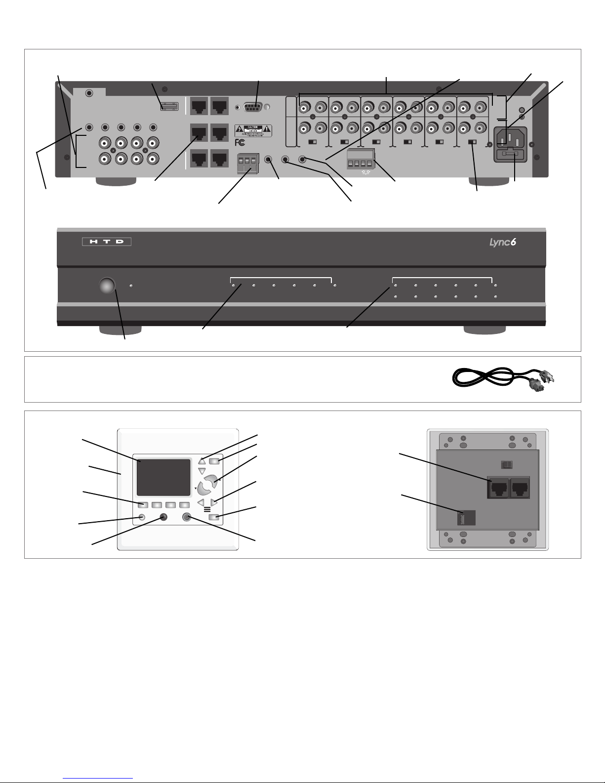
5 Source inputs
USB Flash Drive (MP3) Input
Product Features
RS232 Interface - for system control
and customization through PC
Zones 1 - 6 DI-21 Interface Input
Zone Output - Fixed
Variable
Power Plug
Routed IR Outputs - Pass IR
signals via a single IR emitter
only to the Source selected
bya a zone
Power On/Off button
RJ-45 input (for Cat 5
cable to LyncPad)
IR Input (connect to IR receiving
eye - sold separately)
Zone Status indicates when a zone is
powered on.
Global IR Output - Passes IR
signals via a single or dual IR
emitter regardless of Source
selected by a zone
Trigger Out
System Mute
Trigger In
Source status indicates the strength
of an input signal
Zone Output - Mono/
Stereo Switch
Included with Lync 6
(6) Shielded Stereo Patch Cable (3 feet long)
(for connecting each zone to the multi-channel amplier)
(1) 3.5mm (mono) trigger cable
(1) Power cord
LyncPad
LCD Screen
Magnetically
attached frame
Buttons for
controlling MP3
player
Power/Mute
IR receiving eye
NOTE:The LyncPads are connected to the Lync using Cat5e cable (Cat5, or Cat6 will also work and can be used in place of
Cat5e throughout this manual) with RJ-45 connections at both ends.
Source Selection
Do Not Disturb
Volume Control
RJ-45 connectors
(Cat 5 to Lync)
Zone selection
(intercom)
Talk (intercom) button
3.5mm Source input
5-pin connection
source input panel
3
AC 120V~60Hz
FUSE T2AL/250V
Power Consumption: 180W
ROUTED IR OUT
SOURCE INPUT
KEYPAD PORTS
IR IN
13
SOURCE 13
14
15
16
17
SOURCE 18
MP3
L
ZONE 1 PREOUT ZONE 2 PREOUT ZONE 3 PREOUT ZONE 4 PREOUT ZONE 5 PREOUT ZONE 6 PREOUT
MONO STEREO MONO STEREO MONO STEREO MONO STEREO MONO STEREOMONOSTEREO
R
LRLR
LRLR
LRLRLRLR
LRLRLR
R
L
2
1
4
3
6
5
8
7
10
9
12
11
IR IN
RS232
INTERFACE
GLOBAL
IR OUT
12V/DC
TRIGGER
100mA
IN OUT
System
TRIGGER
AC/DC 3-20V
Mute
Made in T a iwan
CAUTION
T o Prevent Electric Shock,
Do Not Remove Cover. No
User-Serviceable Parts Inside,
Refer Servicing T o Qualified
Service Personnel.
WA RNING
T o Prevent Fire Or Shock
Hazard, Do Not Expose This
Unit T o Rain Or Moisture.
FIXEDVARIABLE
OUTPUT TO AMP
L
ZONE 7 PREOUT ZONE 8 PREOUT ZONE 9 PREOUT ZONE 10 PREOUT ZONE 11 PREOUT ZONE 12 PREOUT
MONO STEREO MONO STEREO MONO STEREO MONO STEREO MONO STEREOMONOSTEREO
R
LRLR
LRLR
LRLRLRLR
LRLRLR
FIXEDVARIABLE
OUTPUT TO AMP
IR IN
Po wer
123456789
10 11 12 13 14 15 16 17 18
123456
789101112
Zone Stat us Source Sign al St reng th
AC 120V~60Hz
FUSE T2AL/250V
Power Consumption: 180W
ROUTED IR OUT
SOURCE INPUT
KEYPAD PORTS
IR IN
13
14
15
16
17
SOURCE 18
MP3
L
ZONE 1 PREOUT ZONE 2 PREOUT ZONE 3 PREOUT ZONE 4 PREOUT ZONE 5 PREOUT ZONE 6 PREOUT
MONO STEREO MONO STEREO MONO STEREO MONO STEREO MONO STEREOMONOSTEREO
R
LRLR
LRLR
LRLRLRLR
LRLRLR
R
L
2
1
4
3
6
5
8
7
10
9
12
11
IR IN
RS232
INTERFACE
GLOBAL
IR OUT
12V/DC
TRIGGER
100mA
IN OUT
System
TRIGGER
AC/DC 3-20V
Mute
Made in T a iwan
CAUTION
T o Prevent Electric Shock,
Do Not Remove Cover. No
User-Serviceable Parts Inside,
Refer Servicing T o Qualified
Service Personnel.
WA RNING
T o Prevent Fire Or Shock
Hazard, Do Not Expose This
Unit T o Rain Or Moisture.
FIXEDVARIABLE
OUTPUT TO AMP
L
ZONE 7 PREOUT ZONE 8 PREOUT ZONE 9 PREOUT ZONE 10 PREOUT ZONE 11 PREOUT ZONE 12 PREOUT
MONO STEREO MONO STEREO MONO STEREO MONO STEREO MONO STEREOMONOSTEREO
R
LRLR
LRLR
LRLRLRLR
LRLRLR
FIXEDVARIABLE
OUTPUT TO AMP
IR IN
DOOR
INTERFACE
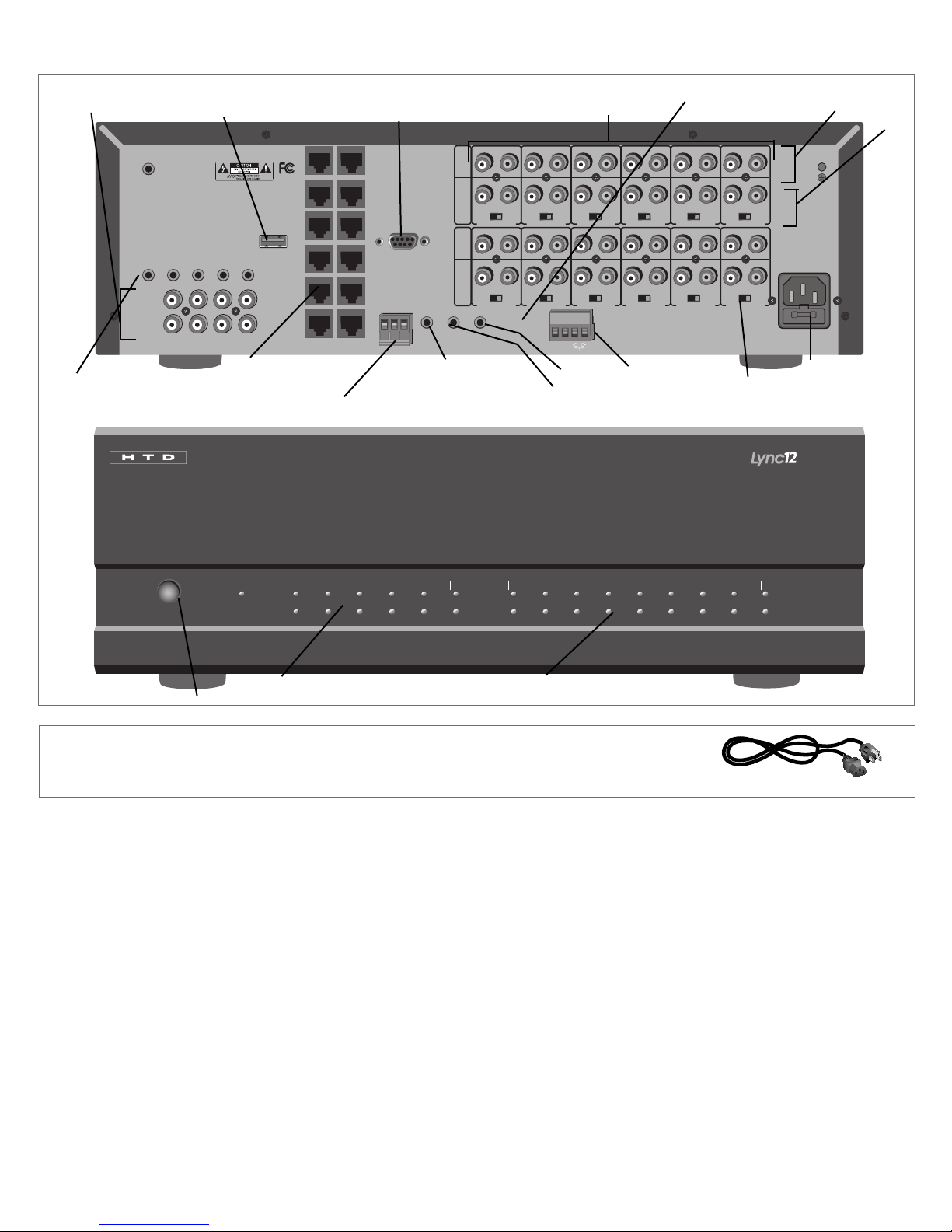
Product Features
(cont.)
Lync 12 Controller
5 Source inputs
Routed IR Outputs - Pass IR signals via a single IR emitter only
to the Source selected by a zone
USB Flash Drive (MP3) Input
RJ-45 input (for Cat 5
cable to LyncPad)
IR Input (connect to IR receiving
eye - sold separately)
RS232 Interface - for system control
and customization through PC
Global IR Output - Passes IR
signals via a single or dual IR
emitter regardless of Source
selected by a zone
Zones 1 - 12
Trigger Out
Trigger In
DI-21 Interface Input
System Mute
Zone Output - Fixed
Variable
Power Plug
Zone Output - Mono/
Stereo Switch
Power On/Off button
Included with Lync 12
(12) Shielded Stereo Patch Cable (3 feet long)
(for connecting each zone to the multi-channel amplier)
Zone Status indicates when a zone is
powered on.
Source status indicates the strength
of an input signal
(1) 3.5mm (mono) trigger cable
(1) 2.5mm to 3.5mm (mono) trigger
cable
(1) Power cord
4
Vol
Vol
Source
Zone
Talk
Source InPower/Mute
DND
Source Input Panel
DND Pow er
Source
Vo lume
Mute
ZONE REMOTE
+
_
5-pin
green
connector
3.5mm
Stereo
Input
Vol
Vol
Source
Zone
Talk
Source InPower/Mute
DND
Vol
Vol
Source
Zone
Talk
Source InPower/Mute
DND
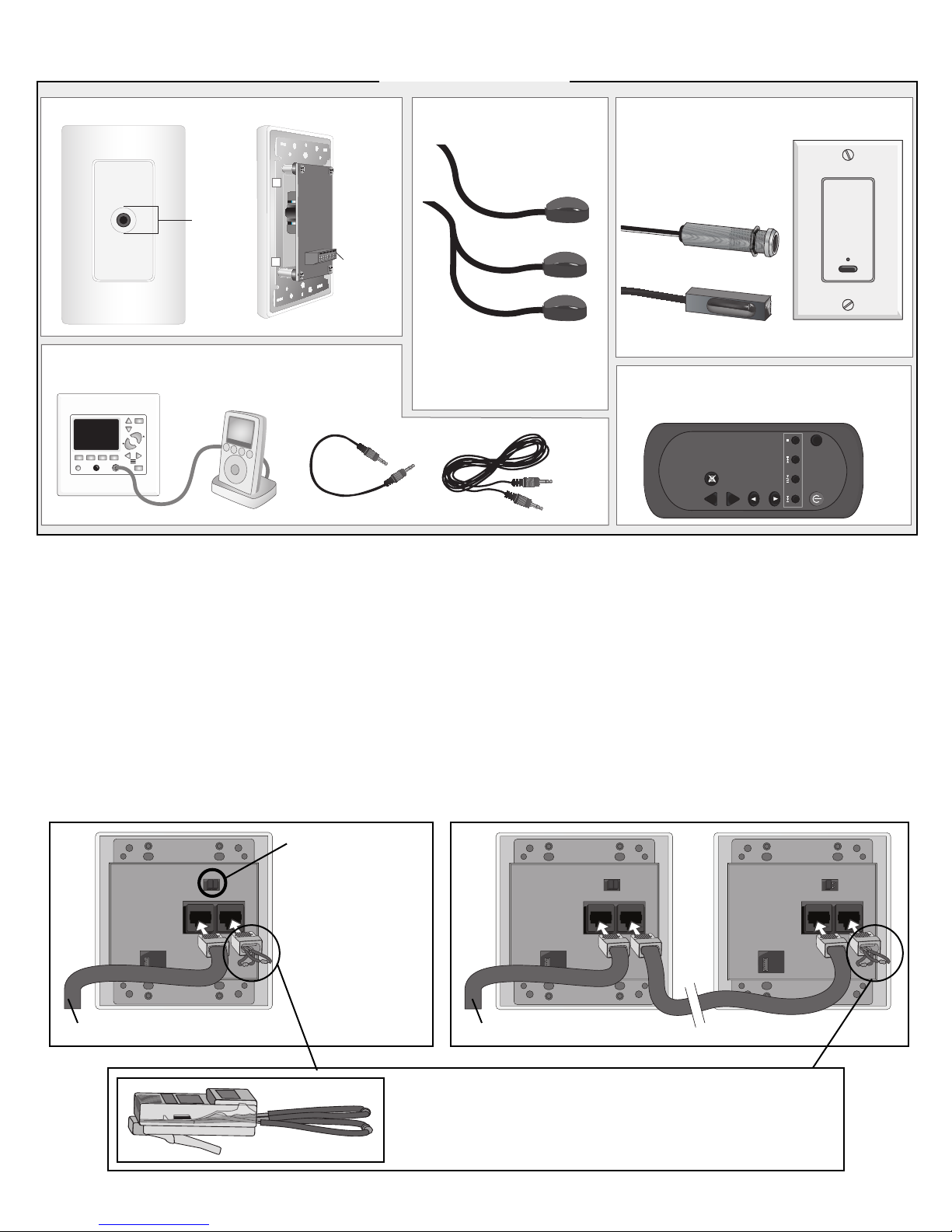
Product Features
(cont.)
Sold Separately
*
IR Emitters
IR-TX2-M
Double
Single
IR Receiving Eyes
Allows you to control audio
components located near
the Lync system, even when
hidden inside of a cabinet or
closet.
IR-RX2-T
3.5mm to 3.5mm Cables
For connecting an MP3 player, iPod®, etc. to 3.5mm input.
Connect emitter(s) to the Lync
and place in front of other
components that you want to
control from within each zone.
IR-RX2
Remote Control
Point at any LyncPad to select the source
IR-RX2-IW
and to control the volume level in that zone.
8 inches
*30 foot, 3-conductor cable included for connecting the Source Input Panel to the back of LyncPad. Adapters sold separately for using Cat5 in place of this cable.
6 feet
Connecting the LyncPad
Connect a properly terminated Cat5 or Cat6 cable to either of the two RJ-45 ports on the back of the LyncPad. The “multiLyncPad terminator” (included with the LyncPad) can be plugged into the other RJ-45 port or left out. The “terminator” is
only REQUIRED when more than one LyncPad are connected to the same zone. For large zones, it is possible to daisychain up to four LyncPads into the same zone. When doing this, you MUST insert the terminator in the last LyncPad in
order for the 3.5 mm inputs to work properly. Please note that a maximum of 12 LyncPads can be connected to a single
Lync 6 controller; a maximum of 24 LyncPads to the Lync 12.
When connecting more than one LyncPad into the SAME zone, each LyncPad must also have a unique combination of
shorting bars installed. Each LyncPad includes 2 shorting bars already installed- this represents one of the four possible
combinations. Removing only the left shorting bar is a second combination; removing only the right is a third; and removing
both shorting bars is a fourth combination. When more than one LyncPad is installed into the same zone, an adjustment
to any one LyncPad will automatically be “mirrored” by the other LyncPads.
“Shorting Bars” -
only adjust if connecting more than
one LyncPad into
the same zone.
To Lync Controller
To Lync Controller
RJ45 multi-LyncPad “terminator” - only REQUIRED when connecting more than one LyncPad into the same zone. However,
it is OKAY to install it in whichever RJ45 terminal is not being
used by the Cat5 or Cat6 cable connecting the LyncPad to the
Lync controller.
Daisy-chained LyncPads
5
12 Channel Amp
Lync
*
Zone 1 - Subzone
Media Room
3 Conductor Cable
(or Cat5/Cat6)
Audio Sources
Home Theater Receiver
Satellite Receiver
*
A room with surround sound should be set up separately. Howerever, it can and usually should be connected to the whole house system as a subzone to a nearby zone.
Cat5e Cable
- Subzone
When possible, co-locate your home theater
and whole-house audio equipment.
AMPLIFIER
12
+
_
AMPLIFIER
12
+
_
OR
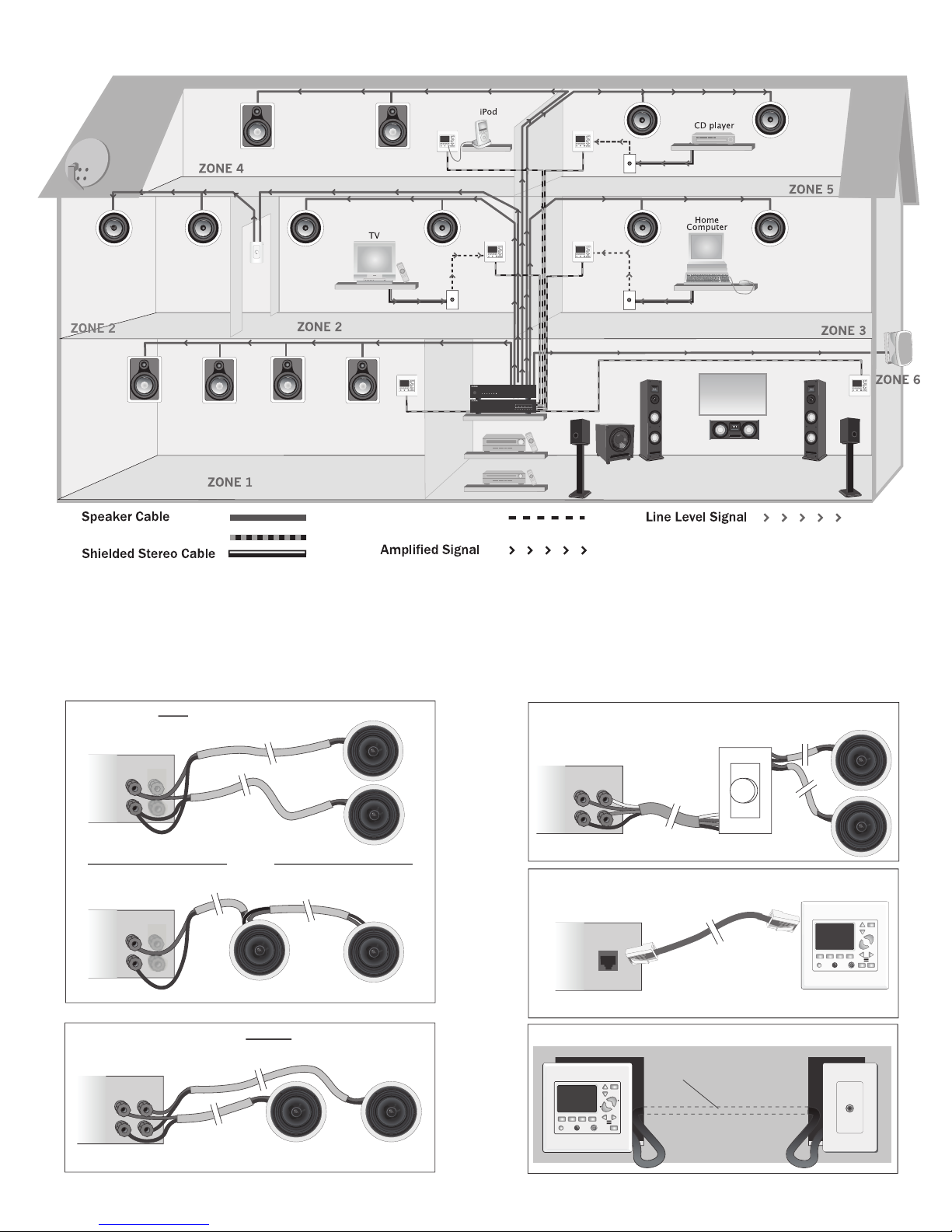
Maximum of TWO 8 ohm speakers per amplifier channel
AMPLIFIER
L
+
_
R
Typical wiring for speakers without an “In-line”
volume control
AMPLIFIER
L
+
_
R
Typical wiring for an “In-line” Volume Control
Controller
Typical wiring of a keypad
(Cat5e or Cat6)
RJ45
RJ45
Note: This connection is only used when independant
volume control within a subzone is required
.
Typical wiring of a Source Input Panel
Vol
Vol
3-conductor cable
(or Cat5/Cat6)
12 Channel Amp
Lync
*
Zone 1 - Subzone
Media Room
3 Conductor Cable
(or Cat5/Cat6)
Audio Sources
Home Theater Receiver
Satellite Receiver
Cat5e Cable
- Subzone
When possible, co-locate your home theater
and whole-house audio equipment.
Wiring Your Home for the Lync System
A room with surround sound (i.e. 5.1 or 7.1) will require a home theater receiver which has its own built-in amplication and multiple source
*
inputs. For this reason, it is not typically set up as a zone on the whole-house audio system. However, it is possible to connect a zone on the
Lync to output to a stereo input on the home theater receiver. In this arrangement, you use the amps in the home theater receiver to power the
zone (or subzone) instead of using two channels on the multi-channel amplier. It is also possible for sources connected to the home theater
receiver to be shared with the whole-house system. For these two reasons, it is often a good idea to establish your central location in close
proximity to the home theater receiver.
6
Zones 1-6
Zone 1
Zone 6
Zone 1
Zone 6
Keypad
Source Input Panel
Sat Rcvr, CD Player, etc.
Any Stereo Source
(1 per zone)
MP3 Player, iPod, etc.
Speakers
Multi-Channel
Amplifier
Lync
Vol
Vol
Cat5e Cable
Power
123456 123456
789101112
DMA-1240
3 Conductor Cable
DMA-1275
Power
Vol 1Vol 2Vol 3Vol 4Vol 5Vol 6 Vol 7Vol 8Vol 9Vol 10 Vol 11 Vol 12
Zones 1-6
Zones 7-12
Zone 1
Zone 3
Zone 9
Zone 6
Zone 7
Zone 12
Zone 1
Zone 12
Keypad
Source Input Panel
Sat Rcvr, CD Player, etc.
Any Stereo Source
(1 per zone)
MP3 Player, iPod, etc.
Speakers
Speakers
Multi-Channel
Amplifier
Multi-Channel
Amplifier
Lync12
Vol
Vol
Cat5e Cable
DMA-1240
3 Conductor Cable
DMA-1275
Power
Vol 1Vol 2Vol 3Vol 4Vol 5Vol 6 Vol 7Vol 8Vol 9Vol 10 Vol 11 Vol 12
DMA-1275
Power
Vol 1Vol 2Vol 3Vol 4Vol 5Vol 6 Vol 7Vol 8Vol 9Vol 10 Vol 11 Vol 12
Power
123456789
10 11 12 13 14 15 16 17 18
123456
789101112
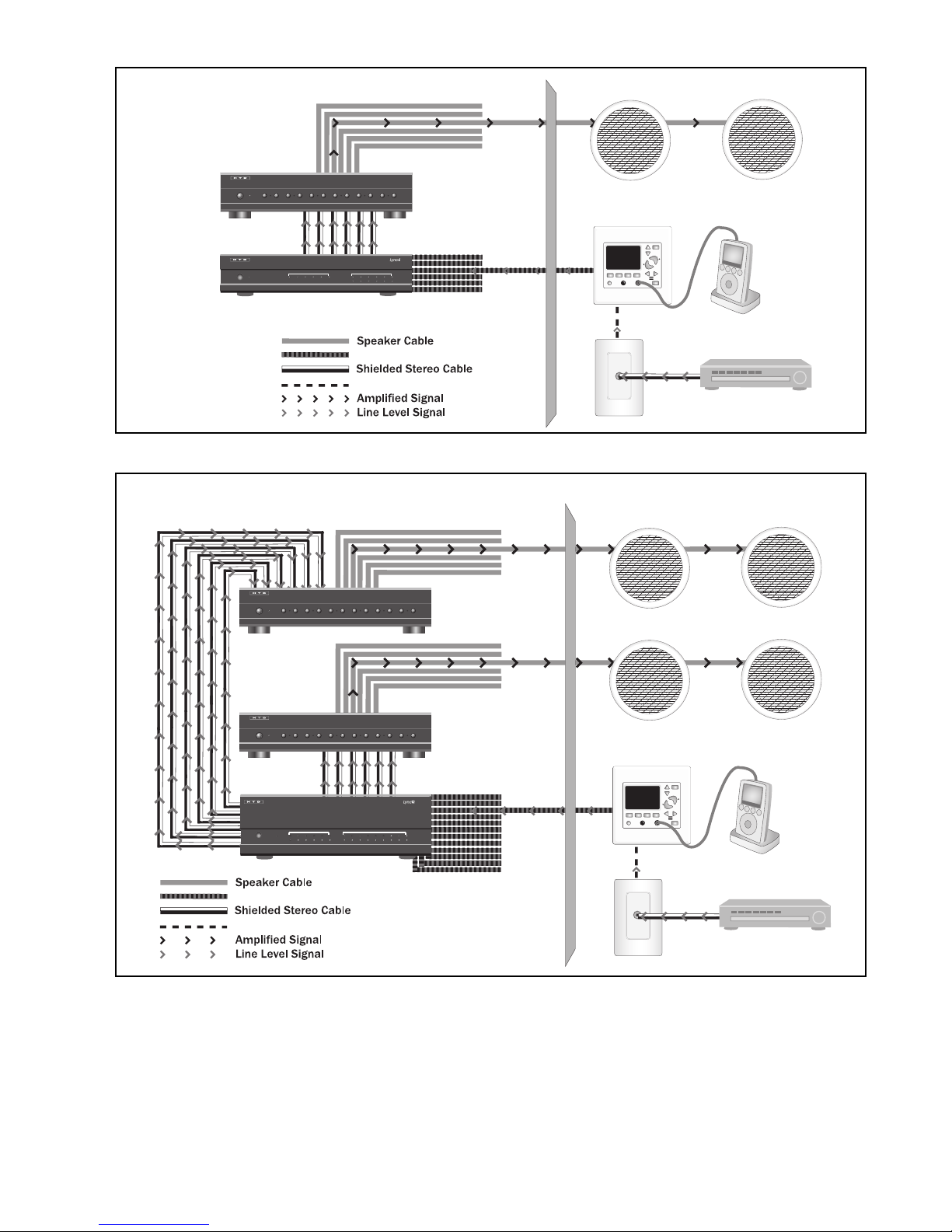
How to Connect
Connection Overview
For Lync6 System
Connection Overview
For Lync12 System
Zone 3
Think of the Lync as the brain of the system. Based on information received from the LyncPads (or PC interface), it determines
what source to play into each zone and the volume level to be sent to the amplier.
LyncPad Connections (see page 8)
The LyncPads are connected to the Lync using Cat5e cable (Cat5, or Cat6 will also work and can be used in place of Cat5e
throughout this manual) with RJ-45 connections at both ends. Up to four LyncPads can be “daisy-chained” together with
Cat5e cable within the same zone, with a maximum of 12 LyncPads for the entire system.
Source Input Panel Connections (see page 8)
Although each LyncPad includes a 3.5mm (1/8”) source input jack on the front for convenience, you may nd it more practical
7
How to Connect
AC 120V~60Hz
FUSE T2AL/250V
Power Consumption: 160W
ROUTED IR OUT
SOURCE INPUT
KEYPAD PORTS
7
8
9
10
11
12
MP3
L
ZONE 1 PREOUT ZONE 2 PREOUT ZONE 3 PREOUT ZONE 4 PREOUT ZONE 5 PREOUT ZONE 6 PREOUT
MONO STEREO MONO STEREO MONO STEREO MONO STEREO MONO STEREO MONO STEREO
R
LRLR
LRLR
LRLRLRLR
LRLRLR
R
L
43
2
1
56
IR IN
RS232
INTERFACE
GLOBAL
IR OUT
12V/DC
TRIGGER
100mA
IN OUT
System
Mute
Made in Ta iwan
CAUTION
To Prevent Electric Shock,
Do Not Remove Cover. No
User-Serviceable Parts Inside,
Refer Servicing To Qualified
Service Personnel.
WARNING
To Prevent Fire Or Shock
Hazard, Do Not Expose This
Unit To Rain Or Moisture.
FIXEDVARIABLE
AC 120V~60Hz
FUSE T2AL/250V
Power Consumption: 160W
ROUTED IR OUT
SOURCE INPUT
KEYPAD PORTS
7
8
9
10
11
12
MP3
L
ZONE 1 PREOUT ZONE 2 PREOUT ZONE 3 PREOUT ZONE 4 PREOUT ZONE 5 PREOUT ZONE 6 PREOUT
MONO STEREO MONO STEREO MONO STEREO MONO STEREO MONO STEREO MONO STEREO
R
LRLR
LRLR
LRLRLRLR
LRLRLR
R
L
43
2
1
56
IR IN
RS232
INTERFACE
GLOBAL
IR OUT
12V/DC
TRIGGER
100mA
IN OUT
System
TRIGGER
AC/DC 3-20V
Mute
Made in Ta iwan
CAUTION
To Prevent Electric Shock,
Do Not Remove Cover. No
User-Serviceable Parts Inside,
Refer Servicing To Qualified
Service Personnel.
WARNING
To Prevent Fire Or Shock
Hazard, Do Not Expose This
Unit To Rain Or Moisture.
FIXEDVARIABLE
IR IN
SOURCE 7
Vol
Vol
Source
Zone
Talk
Source InPower/Mute
DND
(CONT.)
to connect a source input panel to a LyncPad within each zone. The source input panel provides standard stereo RCA-type
connections for connecting most audio components such as DVD players, CD players, iPods, TVs, VCRs and even computers.
The source input panel can be located almost anywhere in the zone.
Amplier Connections (see pages 9-10)
Both variable and xed stereo line-level outputs are provided on the Lync controller for every zone. In most cases, you will use
the variable outputs to connect the Lync controller to a multi-channel amplier in order to control the volume level within a zone
from the LyncPad. Use the xed outputs when you want the volume to be controlled from a separate, more traditional rotary
or slide-type volume control. This is often the case when establishing “sub-zones”. A sub-zone is an area that has indepen-
dent volume control but that is forced to listen to the source selected by the LyncPad in the primary zone. As an example, you
might have a kitchen and dining area that are located side-by-side. In this case, you will often choose to have the kitchen be
the primary zone with volume controlled by the LyncPad, and the dining area’s volume controlled by a more traditional rotary
or slide-type volume control. Depending on your situation, you may or may not need to add more amplier channels than that
already provided by the multi-channel amplier. Please contact HTD for assistance with more complicated setups.
Speaker Connections
Speakers are connected directly to the amplier using speaker cable. For all behind-the-wall installations, CL3-rated cable is
recommended to comply with most building codes.
Audio Component Connections (see page 13)
Any audio component with a stereo analog RCA-type output can be connected directly to one of the 5 Source Inputs located on
the back of the Lync using RCA-type shielded stereo patch cables (not included).
Trigger Out
Use the trigger output to automatically power up an external device with a low voltage trigger input whenever a LyncPad is pow-
ered on. It is often a good idea to connect the Trigger Out to the Trigger In on the external multi-channel amplier using a mono
patch cable with 3.5 mm connectors. For your convenience, one is included with the Lync controller. That way, the multi-chan-
nel amplier will only be powered up when a LyncPad is active. Once all LyncPads have been powered off, the multi-channel
amplier will return to sleep mode.
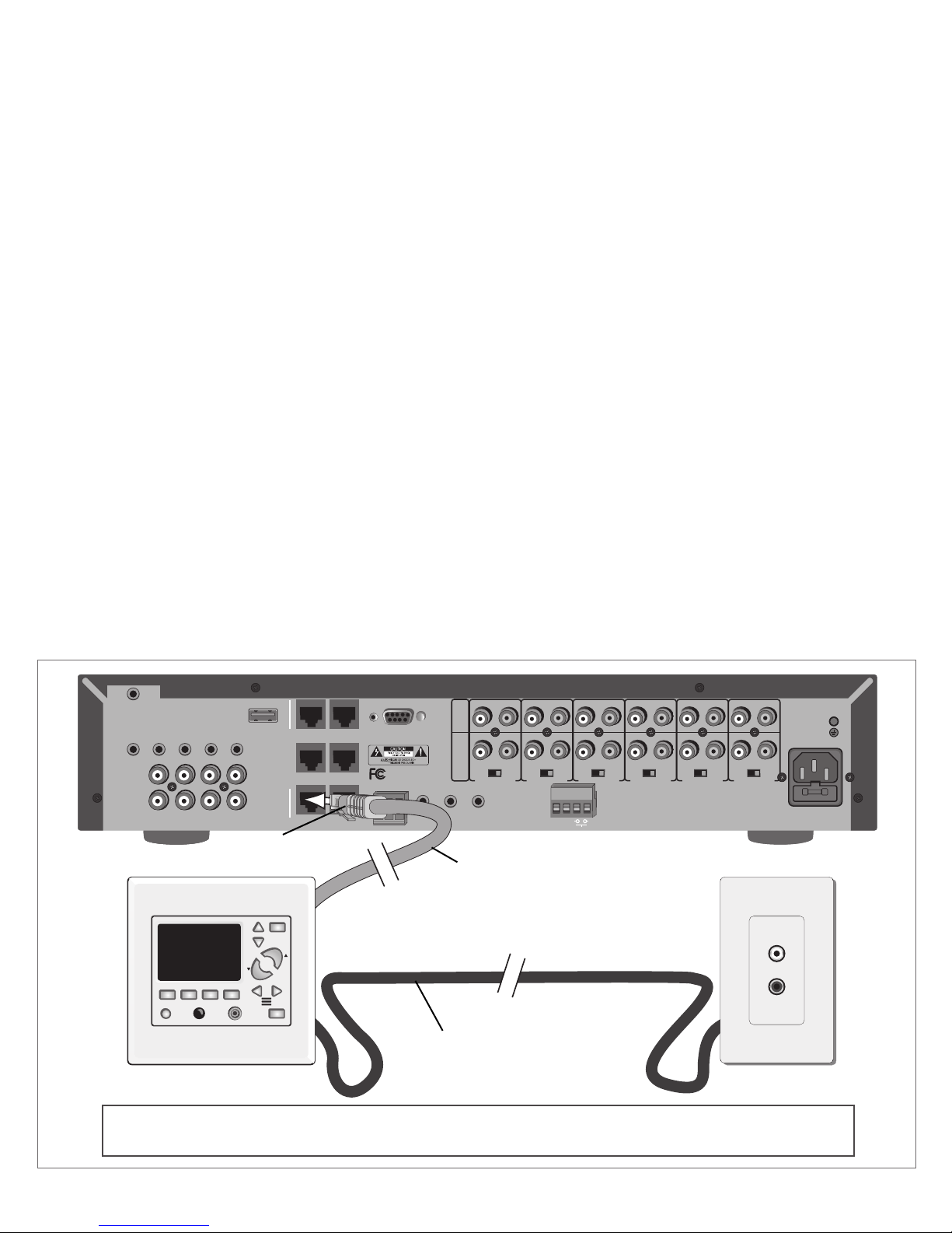
Connecting a LyncPad & Optional Source Input Panel
Important:
Cat5e cable must be terminated to RJ-45 connectors following the 568-A or 568-B standard. (See page 23)
LyncPad
RJ45 Connector
Cat5 cable
3-conductor cable (or Cat5 cable)
Source Input Panel
8
 Loading...