

Page 1
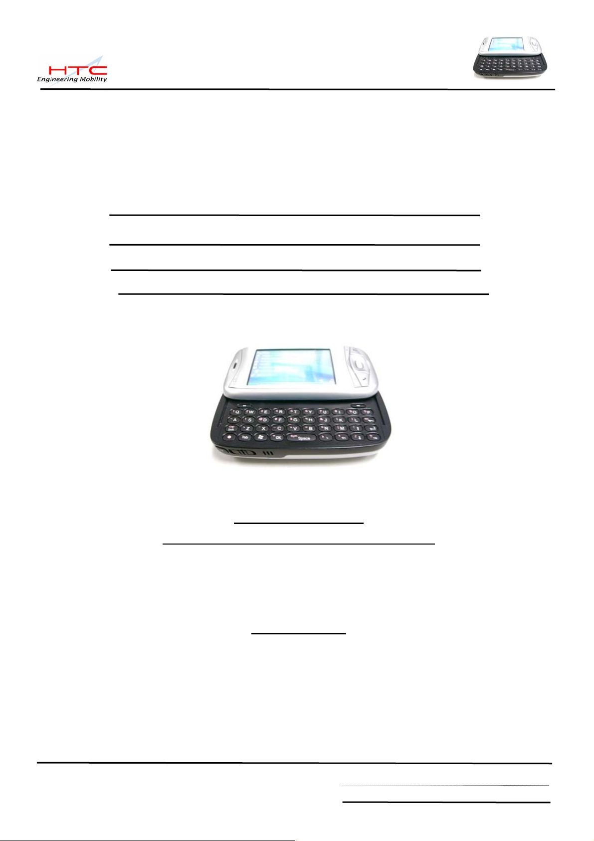
Service Manual
PDA Phone Product
PRODIGY
HTC Proprietary
Confidential T reatment Requested
Rev . A
Nov 16, 2005
HTC Corp.
Engineering Mobility
HTC confidential
© 2001, HTC Corporation. All rights reserved. TOTAL 92 CONT.ON. 2 PAGE NO. 1
Page 2
TITLE: Service Manual for PRODIGY
REV.
NO.
XA
A
DATE CONTENTS DEP. REVISED
GSD
Aug 13, 2005
Nov 16, 2005
First release
Formal release for MP
stage
Technical
Support
GSD
Technical
Support
Johnson Yang
Johnson Yang
APP´D
STGE.PER.
Henry_Lai
Henry_Lai
HTC confidential
© 2001, HTC Corporation. All rights reserved. TOTAL 92 CONT.ON. 3 PAGE NO. 2
Page 3
Table of contents
1. INTRODUCTION ·······································································································5
2. PRODUCT SPECIFICATIONS ·····················································································5
2.1 PRODUCT CONFIGURATION···············································································5
2.2 SPECIFICATIONS OF PRODIGY···········································································6
3. LABELING·············································································································10
3.1 MAIN UNIT REGULATORY LABEL·······································································10
3.2 SERIAL NUMBER DESCRIPTION ········································································10
4. SERVICING TOOLS ································································································11
5. ASSEMBLING AND DISASSEMBLING ········································································12
5.1 DISASSEMBLING·····························································································12
5.2 ASSEMBLING··································································································26
5.3 NOTIFICATION ONCE PERFORMING GOLDEN CAP REPLACEMENT························37
5.4 NOTIFICATION ONCE PERFORMING M/B REPLACEMENT·····································38
5.5 NOTIFICATION ONCE PERFORMING LCM REPLACEMENT····································39
5.6 NOTIFICATION ONCE PERFORMING RIGID-FLEX BD REPLACEMENT·····················40
5.7 NOTIFICATION ONCE PERFORMING LCM HOUSING OR KEYPAD BEZEL REPLACEMENT········· 41
6. EQUIPMENT OF PROBLEM DIAGNOSTICS ································································43
6.1 LIST OF TEST JIGS··························································································43
6.2 H/W REQUIREMENT FOR PC···········································································43
6.3 SOFTWARE REQUIREMENT ·············································································43
7. DIAGNOSTIC PROGRAMS······················································································44
7.1 LIST OF TEST ITEMS ······················································································44
7.2 TEST ITEMS OPERATION·················································································45
7.3 HOW TO EXECUTE DIAG TEST PROGRAM·························································45
8. BATTERY TEST/JUDGEMENT PROCEDURE ······························································46
8.1 CERTIFICATION FLOW ·····················································································46
8.2 CURRENT CONSUMPTION MEASUREMENT·························································47
8.3 WHOLE UNIT CHARGE AND DISCHARGE TEST····················································50
8.4 BATTERY PERFORMANCE ON UNIT WITH RUN DOWN PROGRAM ························51
9. LCM INSPECTION CRITERIA ··················································································55
10.RF TEST·············································································································57
10.1 GSM FUNCTION TEST···················································································57
10.2 H/W REQUIREMENT ·····················································································57
HTC confidential
© 2001, HTC Corporation. All rights reserved. TOTAL 92 CONT.ON. 4 PAGE NO. 3
Page 4
10.3 TEST CONNECTION························································································57
10.4 RF ANTENNA TEST SPEC. ············································································58
10.5 BLUETOOTH FUNCTION TEST ········································································62
10.6 WLAN FUNCTION TEST················································································66
11. FIRMWARE OF OS/ RADIO UPGRADE····································································68
11.1 RUU·········································································································68
11.2 UPLOAD FIRMWARE CODE FROM MASTER UNIT TO MINI-SD CARD ·················74
11.3 USE PRE-LOADED MINI-SD CARD TO RE-FLASH UNIT ··································79
12.TROUBLE SHOOTING AND REPAIR·········································································80
13 SPARE PART LIST·································································································85
13.1 UNIT SPARE PART LIST····················································································85
13.2 BOARD LEVEL SPARE PART LIST ······································································87
14. APPENDIX···········································································································88
A. CUSTOMER, RETAILER MISJUDGMENT·······························································88
B. HOW TO PERFORM WARM -RESET AND HARD-RESET ·········································90
C. REMOVE MAIN BATTERY BEFORE TURN OFF UNIT···············································90
D. RE-FLASH AGAIN ONCE FAILED DURING RE-FLASH PROCESS·······························90
E. IF UNIT HANG ON 100% WHILE USING RUU RE-FLASH········································91
F. IF THE SCREEN IS FROZEN AFTER RE-FLASH ·····················································91
G. IF UNIT CAN NOT TURN ON ················································································91
H. COMPONENT COMPATIBLE REQUEST·································································91
I. DIAGNOSTIC CARD VS. UNIT’S SPL VERSION ·····················································92
HTC confidential
© 2001, HTC Corporation. All rights reserved. TOTAL 92 CO N. 5 PAGE NO. 4
NT.O
Page 5
1. Introduction
This manual provides the technical information to support service activities of PDA phone
(Prodigy). This document contains highly confidential information, any or all of this document
should not be revealed to any third party.
2. Product Specifications
2.1 Product Configuration
Standard Package
ITEM CONTAINS
1 Main Unit
2 Stylus
3 AC Adapter w/ mini –USB plug
4 Stereo wired headset with microphone
5 Carrying Case
6 Car Kit
7 User’s Manual, Quick start guide, Sync., S/W (CD)
8 Battery
9 Travel charger
10 User’s Manual
HTC confidential
© 2001, HTC Corporation. All rights reserved. TOTAL 92 CONT.ON. 6 PAGE NO. 5
Page 6
2.2 Specifications of Prodigy
Item Specification
Soldering status z Meet Lead-free requirement
Platform z Microsoft Windows Pocket PC phone edition
Outside Dimensions z 58mm(W) x 109mm(H) x 23.7mm (T)
Weight z Less than 160 g (Main unit with battery pack)
Battery z Removable rechargeable Lithium Polymer battery
z PDA form factor integrated quad-band GSM/EDGE,
Bluetooth, WiFi, 1.3/2 mega-pixel camera, and sliding
QWERTY keyboard
z 1250 mAH
z Battery Life:
* WMA: 12 hours
* WMV: 8 hours
z Talk time: 3.5 ~ 5 hrs
z Standby Time: 150 ~ 200 hrs
AC Adapter z AC input 100 ~ 240 Vac, 50/60 HZ
z DC output : 5V / 1A (typical)
GPRS/GSM (Tri-band)
module
z Quad-Band ( 850/900/1800/1900)MHz
z Internal Antenna
z Audio codec: AMR, EFR, FR, HR
z Supplement services
* Call holding/waiting/ forwarding
* CLI (Call line Identity)
* Display own number
* Network selection
* Cell broadcast
* Multi-party conference call
* Spool Icon
* Network lock
HTC confidential
© 2001, HTC Corporation. All rights reserved. TOTAL 92 CONT.ON. 7 PAGE NO. 6
Page 7
EDGE functionality z EGPRS Class B,
z Multi-slot Class 10
z PBCCH
z Incremental Redundancy
SIM z 1.8V/3V SIM Operation
z SIM Application Tool Kit release 98 class 3
z Over the Air (OTA) programming
z FDN/AND/SDN
z Security PIN 1&2 control
Memory
z ROM: 128MB (for program and users’ storage)
z RAM: 64 MB DDR SDRAM
Processor/Chipset z TI OMAP 850
LCD Module z 64K-color TFT Transflective LCD with white LED back
light
z 2.8” 240 x 320 dots resolution
z Sensitive Touch Screen
Interface
z One Infrared port IrDA SIR
z 1.8V/3V SIM card
z Mini-SD card slot (top)
z 2.5ψ stereo audio jack
z External antenna connector
Stylus z Lock type mechanism
Keyboard/Button/Switch z Five way navigation button
z Power button
z Volume control button (up & down)
z 2 phone button, Send (Yes) & End (No)
z 2 AP buttons ( message-left, IE-right)
z 2 soft keys
z Camera shutter button
z Voice command/Voice recorder button
z Reset Switch
z RF button
z Sliding QWERTY keyboard with 39 keys + 2 soft keys
HTC confidential
© 2001, HTC Corporation. All rights reserved. TOTAL 92 CONT.ON. 8 PAGE NO. 7
Page 8
Notification z One Bi-color LED for GSM standby, GSM message,
GSM network status, notification, and charging status.
z Two respective (blue and green) LEDs for for
Bluetooth/ WiFi notification.
z Notification by sound, Message, Vibration on the
display.
CMOS Camera Main Camera (manufacture option)
z CMOS 1.3 mega Pixel with fixed lens
z Or CMOS 2.1 mega Pixel with macro lens
z Video/flash light
z Preview Mirror
Audio z Build-in Microphone
z Receiver
z Dual speaker on both sides
z Loud speaker for Hands-free supported
z Full duplex
z WAV/WMA/AMR/AAC/MP3 codec.
z 16 bits with 8KHz,11 KHz, 22KHz,44.1 KHz,
sampling rate
Bluetooth z Compliant with V1.2
z Class 2 transmit power
z Supported profiles:
¾ Generic Access profile
¾ Serial Port profile
¾ Headset profile
¾ Object Push profile
¾ DUN profile
¾ Heads-free profile
¾ Generic Object Exchange profile
¾ HID profile
z Co-exist with WiFi
HTC confidential
© 2001, HTC Corporation. All rights reserved. TOTAL 92 CONT.ON. 9 PAGE NO. 8
Page 9

WiFi z IEEE 802.11b/g compliant
z Internal WLAN Antenna
z 11, 5.5, 2 and 1 Mbps per channel, auto fallback for
extended range
z ELP mode
z Support 802.11i&AES
z Security
* WPA authentication
z QoS
* 802.11 WME QoS
* 802.11e is preferred
*Fast AP to AP handover
Regulatory z PTCRB
z R&TTE: EMC/EMI, CEM, Safety
z FCC
z WiFi Certification
z Bluetooth Certifiaction
z Microsoft Windows Mobile version 5.0 logo
Accessories z Carrying Case
z AC adapter with mini-USB plug
z Sync. Cable (mini-USB)
z Battery (rechargeable and replaceable)
z Car adapter
z Stylus
z Car Kit w/car stereo mute function
z Stereo-wired headset with microphone
z Mono bluetooth headset with microphone
z Keyboard
z Cradle (optional)
z User manual, quick start guide, Sync. S/W (CD)
z Travel charger
HTC confidential
© 2001, HTC Corporation. All rights reserved. TOTAL 92 CONT.ON. 10 PAGE NO. 9
Page 10
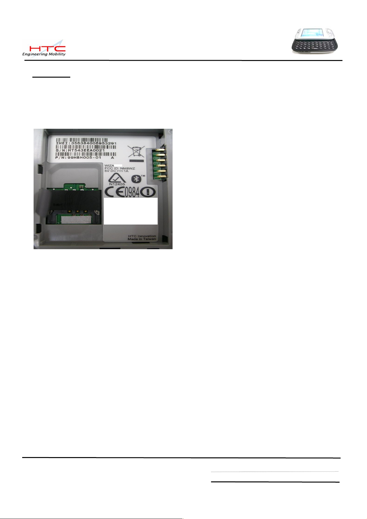
3. Labeling
3.1 Main unit Regulatory label (Stick on the keypad housing of main unit)
Here is an example only. Actually printing format is depended on customer’s request.
Repair center need to re-print new regulatory label once replacing M/B for new IMEI,
As to printing format, please refer to returned unit from end user.
Label Characteristic:
Material: polyester
Color: pantone 422c
Ink: pantone 425c
3.2 Serial number description
For S/N: SSYWWPPZZZZZ
SS: SITE CODE --> HT or TW
Y: Year Last Digital of the Year.
WW: Week Code : 01 ~ 54
PP: Product Code : By HTC define
ZZZZZ: Serial Number (00001 ~ 99999) Use Base 10
HTC confidential
© 2001, HTC Corporation. All rights reserved. TOTAL 92 CONT.ON. 11 PAGE NO. 10
Page 11
4. Servicing Tools
This chapter provides information for the servicing tools for Prodigy.
Repair Level Definition
Unit
L0 Accessory test and unit swap
L1 Unit Test and ROM Re-flash
L2 Refurbishment and Module Swap +L1
L2.5 M/B Repair(connecter, button, MIC…) +L2
List of Servicing Tools
level No. Item Use for Remark
L 1
1 Mini USB DATA interface
Cable
Check for mini USB
communication; RUU re-flash
2 Earphone Headset For Audio test.
3 AC Adapter Transfer AC to DC for Unit
4 WLAN AP For WiFi test
5 Mini Memory Card with Diag.
For unit Diag. test HTC design
test program (need be
encoded by HTC)
6 128MB mini SD memory card
( must be encoded by HTC)
7 Unit current consumption test
fixture
8 Power supply
9 Current Meter
For unit Re-flash ROM code
transfer to mini SD card
Measure Unit current
consumption
HTC design
HTC design
10 Mobile tester For RF test
11 Special Made Plastic Stick Assembly & Disassembling HTC special
L 2
12 Hand tools Assembly & Disassembling
13 Label printer Print agency label if replacing
tools
M/B
14 Lead-free Soldering station Board level repair L 2.5
15 Air heater Board level repair
HTC confidential
© 2001, HTC Corporation. All rights reserved. TOTAL 92 CONT.ON. 12 PAGE NO. 11
Page 12
5. Disassembling and Assembling
5.1 Disassembling
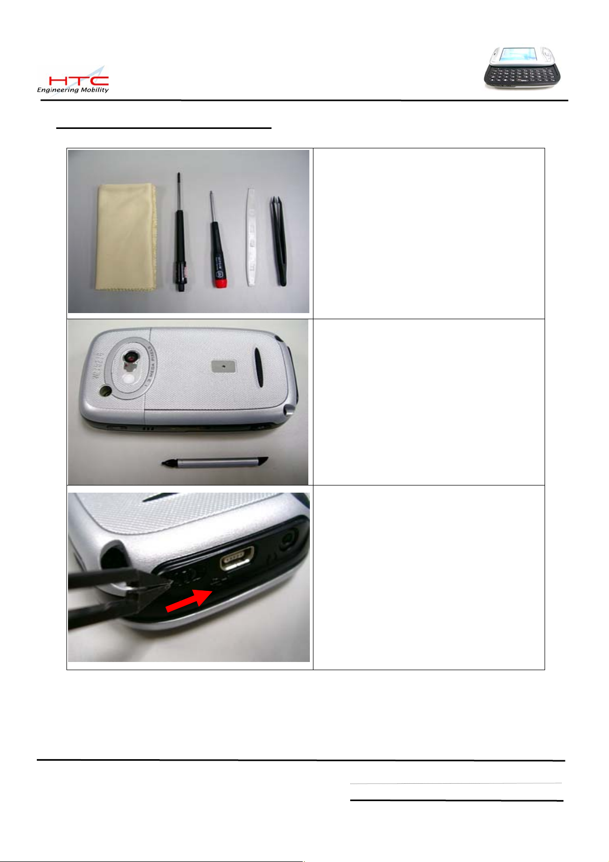
Tools needed of Assembling and
Disassembling Prodigy
From left to right in the picture
1. Lens Cleaning Tissue.
2. Philip Screw Driver #0.
3. Torex Screw Driver T5X40
4. Special Made Plastic Stick.
5. Tweezers.
Remove the Stylus, mini-SD Card slot
Filler, and protection rubber of antenna
connector.
Next, Remove the battery cover by
releasing lock switch
HTC confidential
© 2001, HTC Corporation. All rights reserved. TOTAL 92 CONT.ON. 13 PAGE NO. 12
Page 13
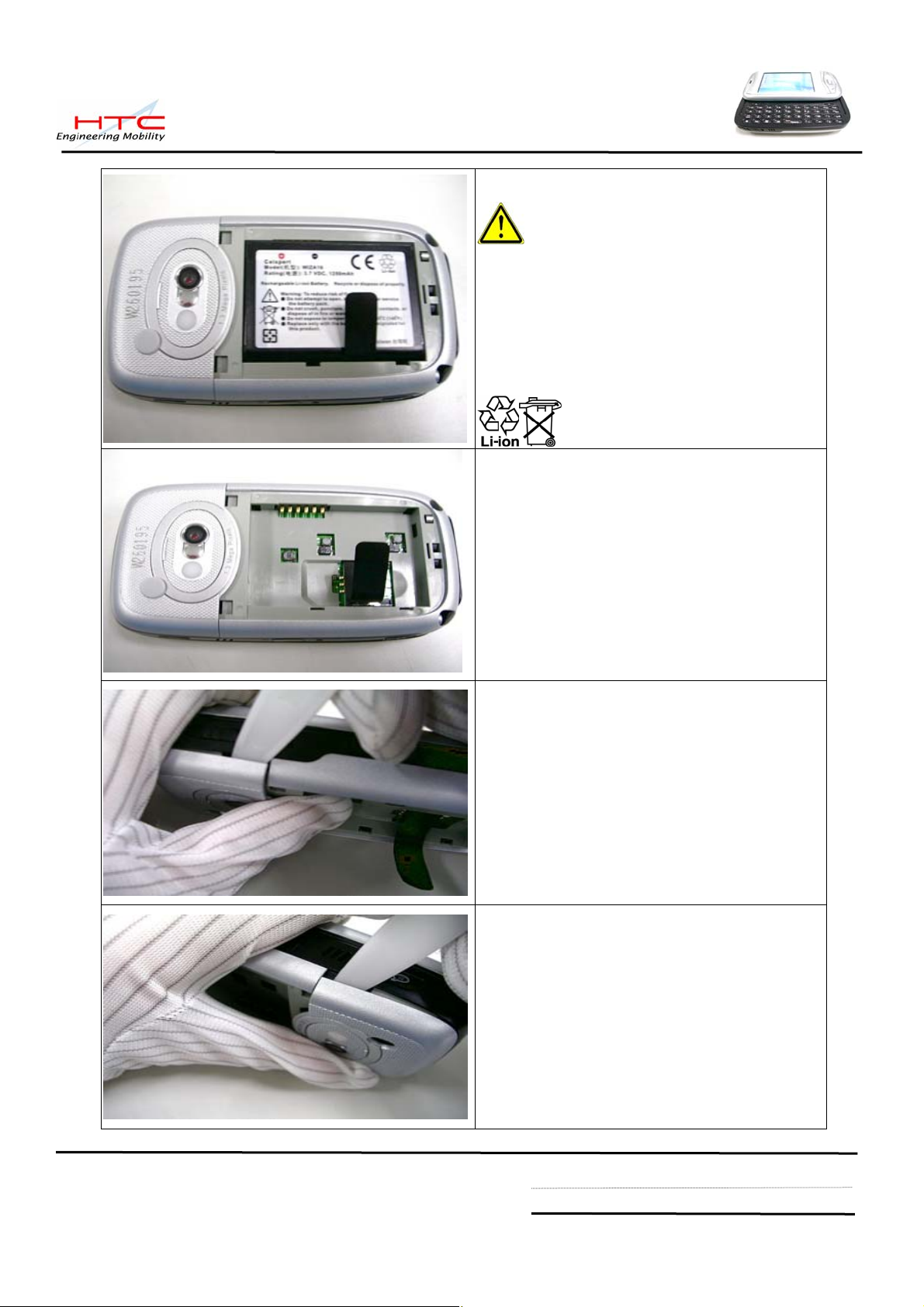
Remove battery cover
Warning: To reduce risk of fire or
burns, do not disassemble, crush,
puncture, short external contacts, or
dispose of in fire or water. Replace only
with specified batteries. Recycle or
dispose of used batteries properly
Remove main battery from unit
Use the plastic stick to Insert and gently
twist into the gap between keypad housing
and antenna cover.
Unlock the inside hook
HTC confidential
© 2001, HTC Corporation. All rights reserved. TOTAL 92 CONT.ON. 14 PAGE NO. 13
Page 14
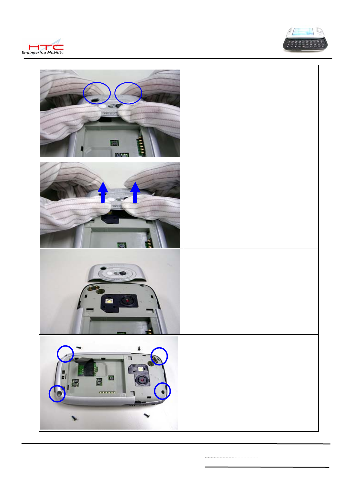
There are 2 hook on the top side of
Antenna cover,
Use 2 thumbs to push the bottom of
antenna cover
Take care of disassembling Antenna cover
during the process, it is easy to damage
the hook of Antenna cover
Antenna cover is removed
Release 4 screws from keypad housing
HTC confidential
© 2001, HTC Corporation. All rights reserved. TOTAL 92 CONT.ON. 15 PAGE NO. 14
Page 15
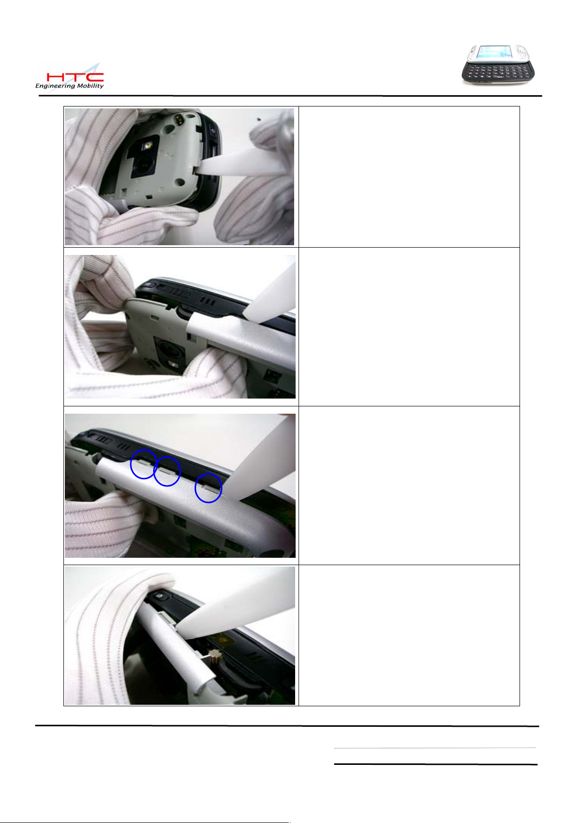
To insert plastic stick into the gap of top of
keypad housing
Unlock hook
There are 3 hooks at right side
Another 3 hooks at left side
HTC confidential
© 2001, HTC Corporation. All rights reserved. TOTAL 92 CONT.ON. 16 PAGE NO. 15
Page 16
Disassembly keypad housing
The keypad housing is removed
There are 2 parts on the keypad housing,
1. Flash light
2. Vibrator
HTC confidential
© 2001, HTC Corporation. All rights reserved. TOTAL 92 CONT.ON. 17 PAGE NO. 16
Page 17
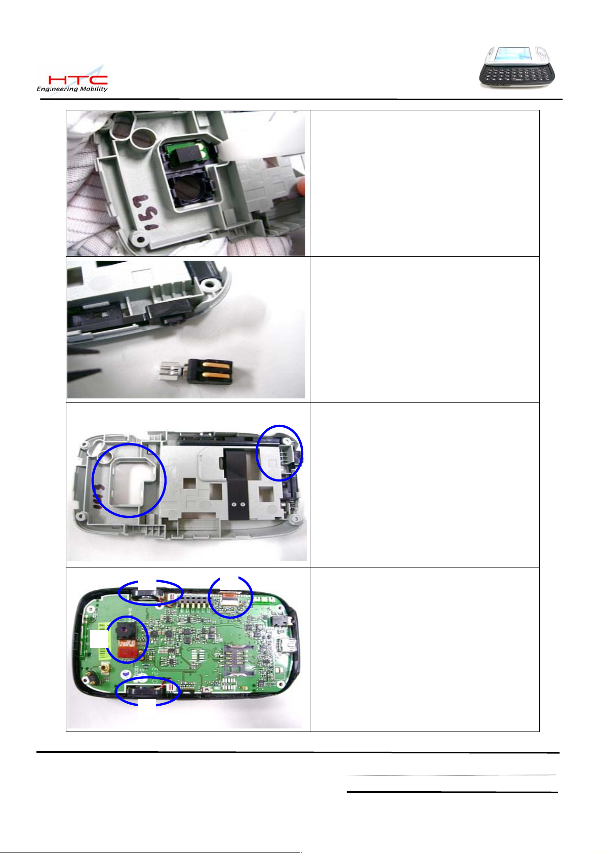
Use Plastic stick to unlock hooks of flash
light module
Use tweezes to remove Vibrator
Flash-light module and Vibrator
are removed
3 4
Following need to be removed
1. Camera
2. Speaker
1
3. Speaker
4. Keyboard FPC cable
2
HTC confidential
© 2001, HTC Corporation. All rights reserved. TOTAL 92 CONT.ON. 18 PAGE NO. 17
Page 18

Remove Camera
Remove speakers
Both side speakers are removed
Disconnect keyboard FPC cable
HTC confidential
© 2001, HTC Corporation. All rights reserved. TOTAL 92 CONT.ON. 19 PAGE NO. 18
Page 19

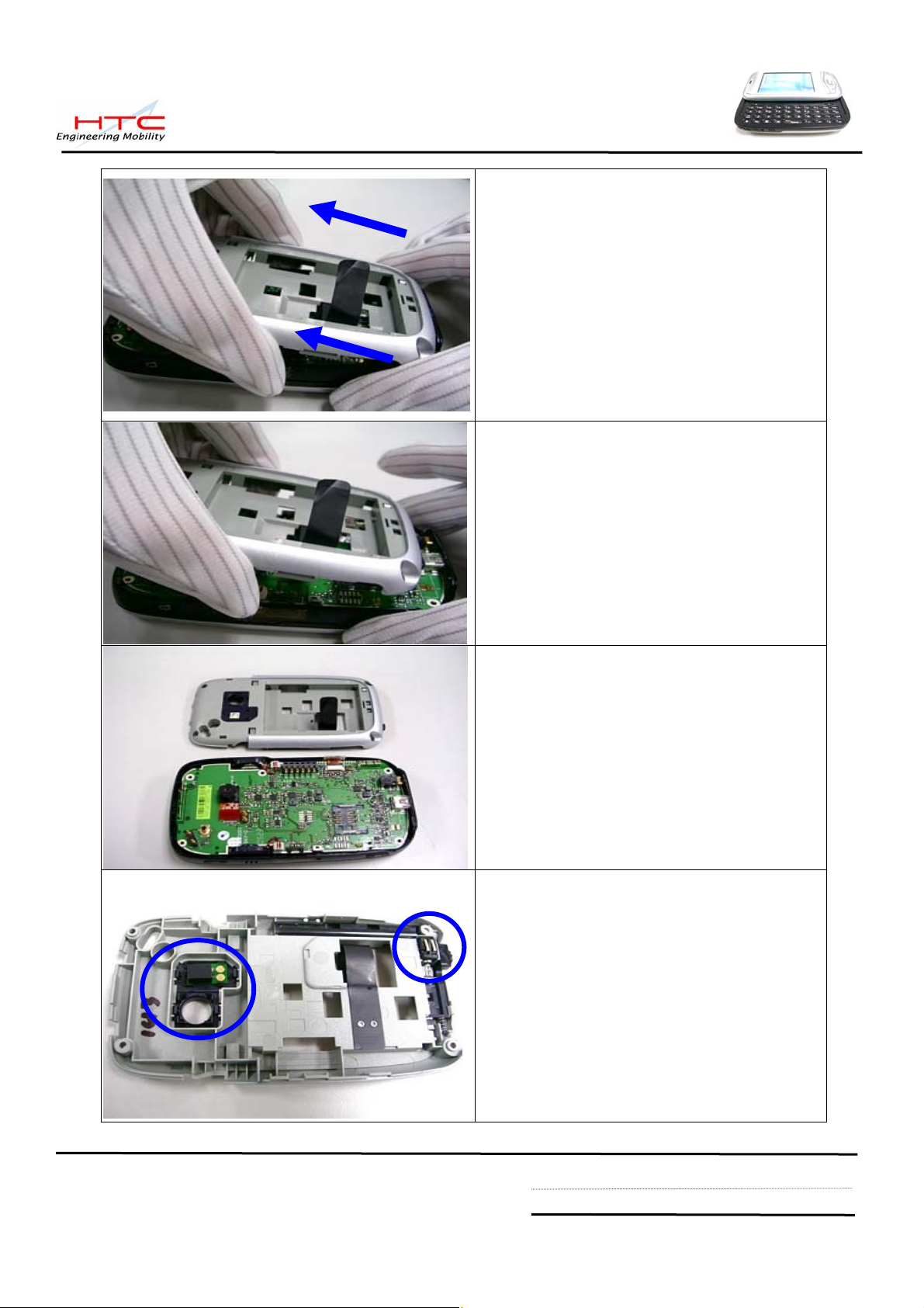
Shift the Keypad bezel as left picture
Take care the record button while
disassembly main board
Use plastic stick to raise main board
The main board is connected with
Rigid-Flex Board
HTC confidential
© 2001, HTC Corporation. All rights reserved. TOTAL 92 CONT.ON. 20 PAGE NO. 19
Page 20
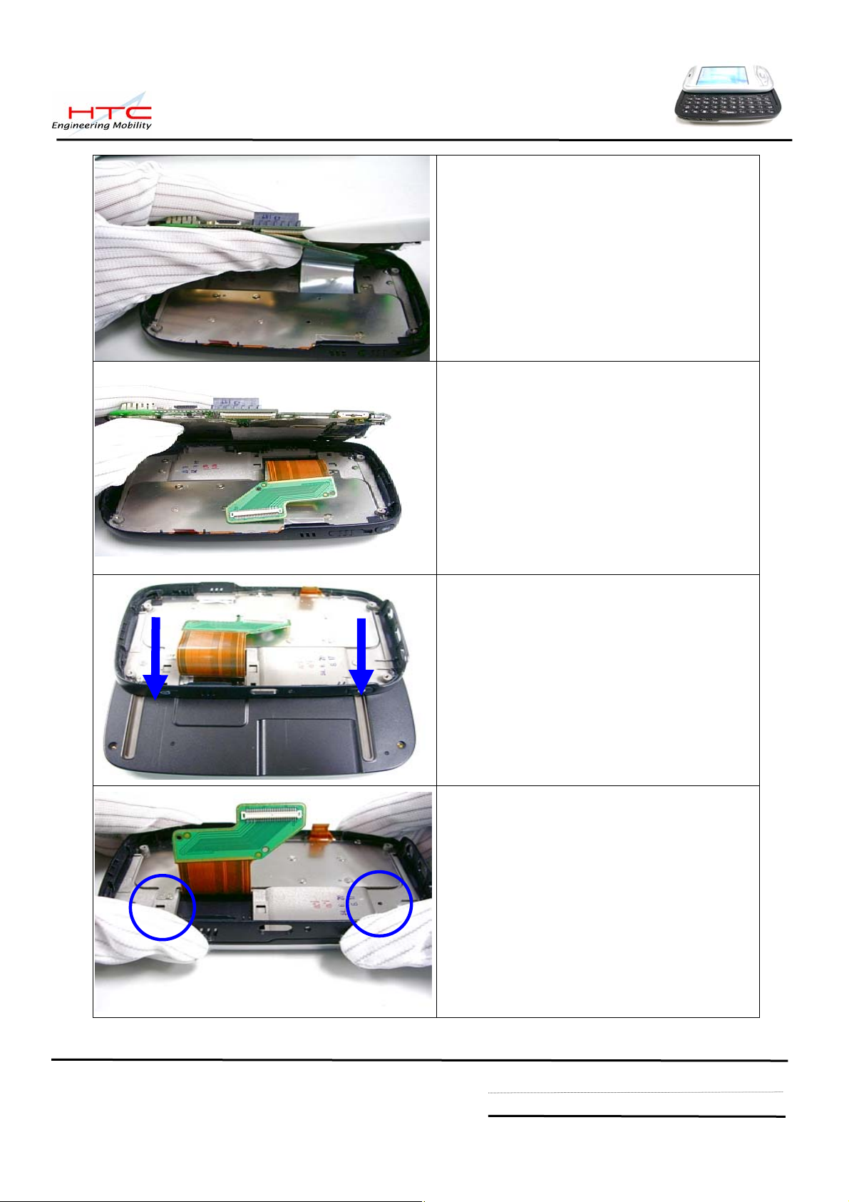
Disconnect the FPC cable
The main board is released
Shift the keypad bezel back
Disassembly 4 screws on both sides.
HTC confidential
© 2001, HTC Corporation. All rights reserved. TOTAL 92 CONT.ON. 21 PAGE NO. 20
Page 21
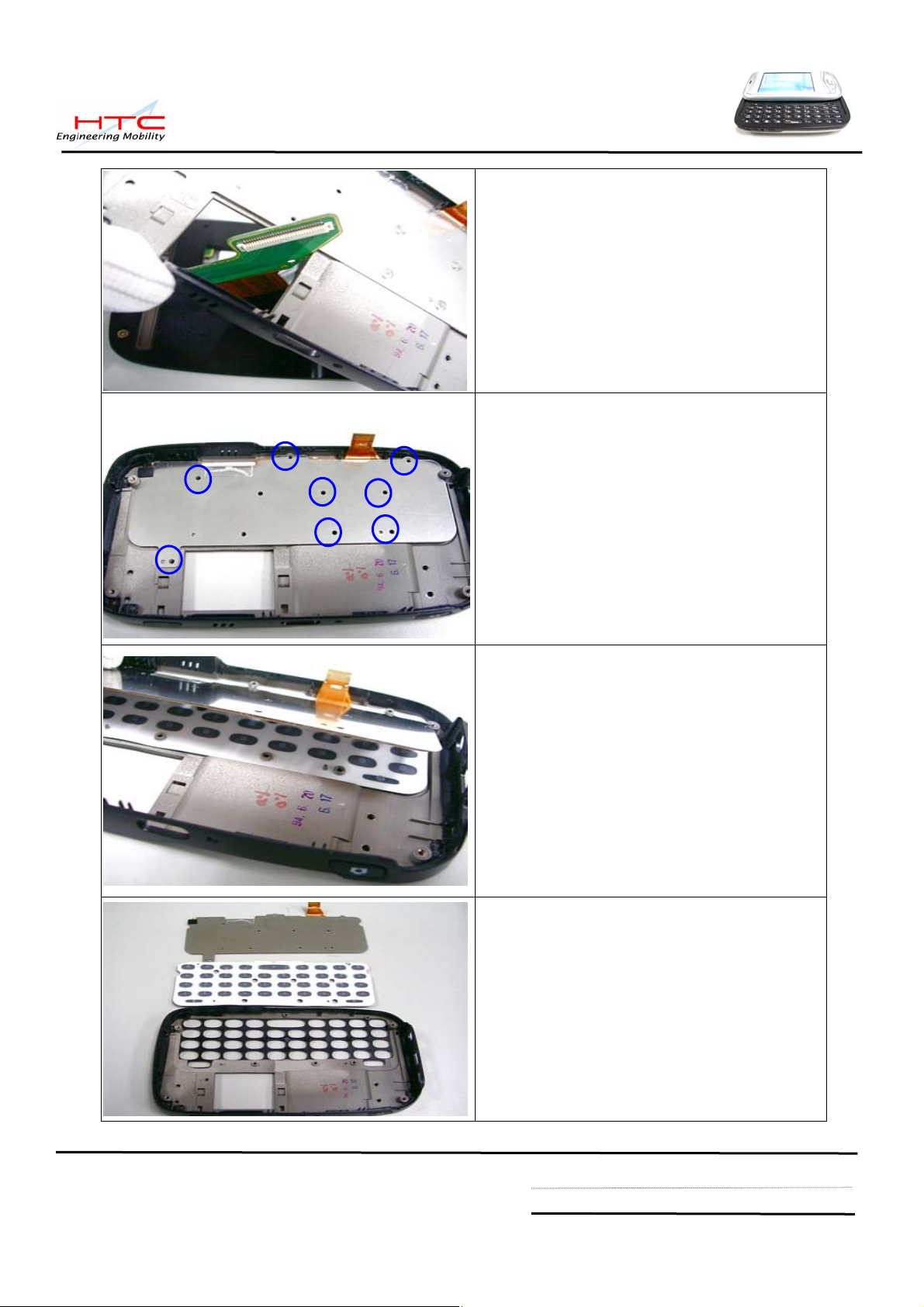
Disassembly keypad bezel of keyboard
Remove 8 screws
Disassembly keyboard
Keyboard and keypad are moved
Caution:
Don’t need to separate FPC keyboard and
metal plate
HTC confidential
© 2001, HTC Corporation. All rights reserved. TOTAL 92 CONT.ON. 22 PAGE NO. 21
Page 22
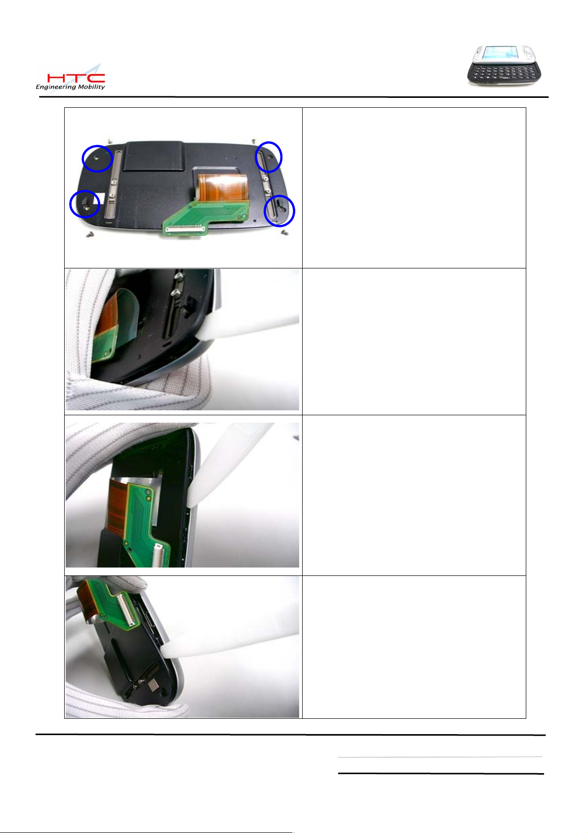
Remove 4 screws
Use plastic stick to unlock the hook
There are 6 hooks at both side, and 2
hooks at top and bottom side
Unlock another side
HTC confidential
© 2001, HTC Corporation. All rights reserved. TOTAL 92 CONT.ON. 23 PAGE NO. 22
Page 23
Let FPC cable through the space of
Housing case, Separate LCM housing and
LCM Bezel
Remove protect tape of LCM connector
from the Rigid-Flex Board
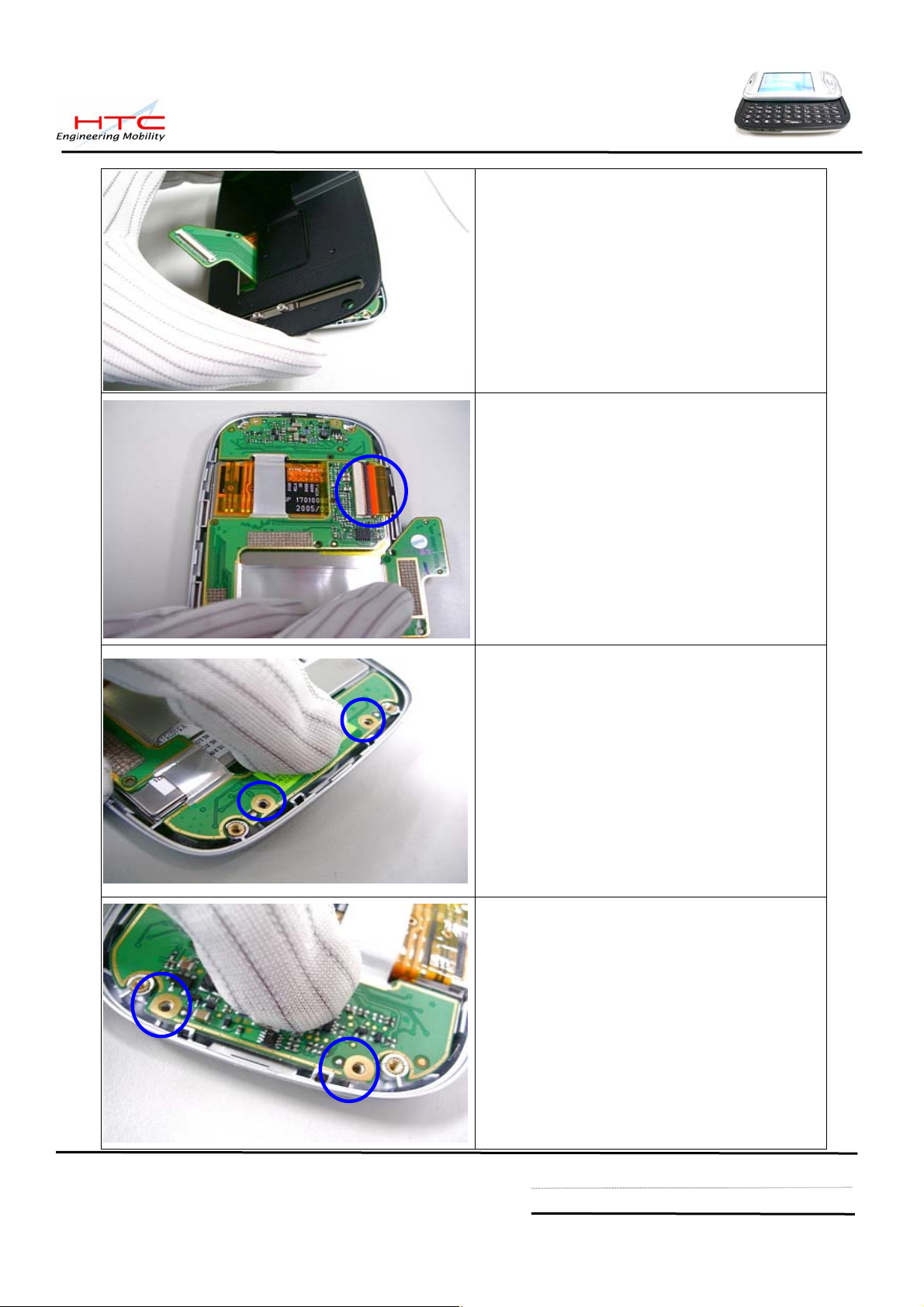
Remove 2 screws of top side from
Rigid-flex board
Remove 2 screws of bottom side from
Rigid-flex board
HTC confidential
© 2001, HTC Corporation. All rights reserved. TOTAL 92 CONT.ON. 24 PAGE NO. 23
Page 24
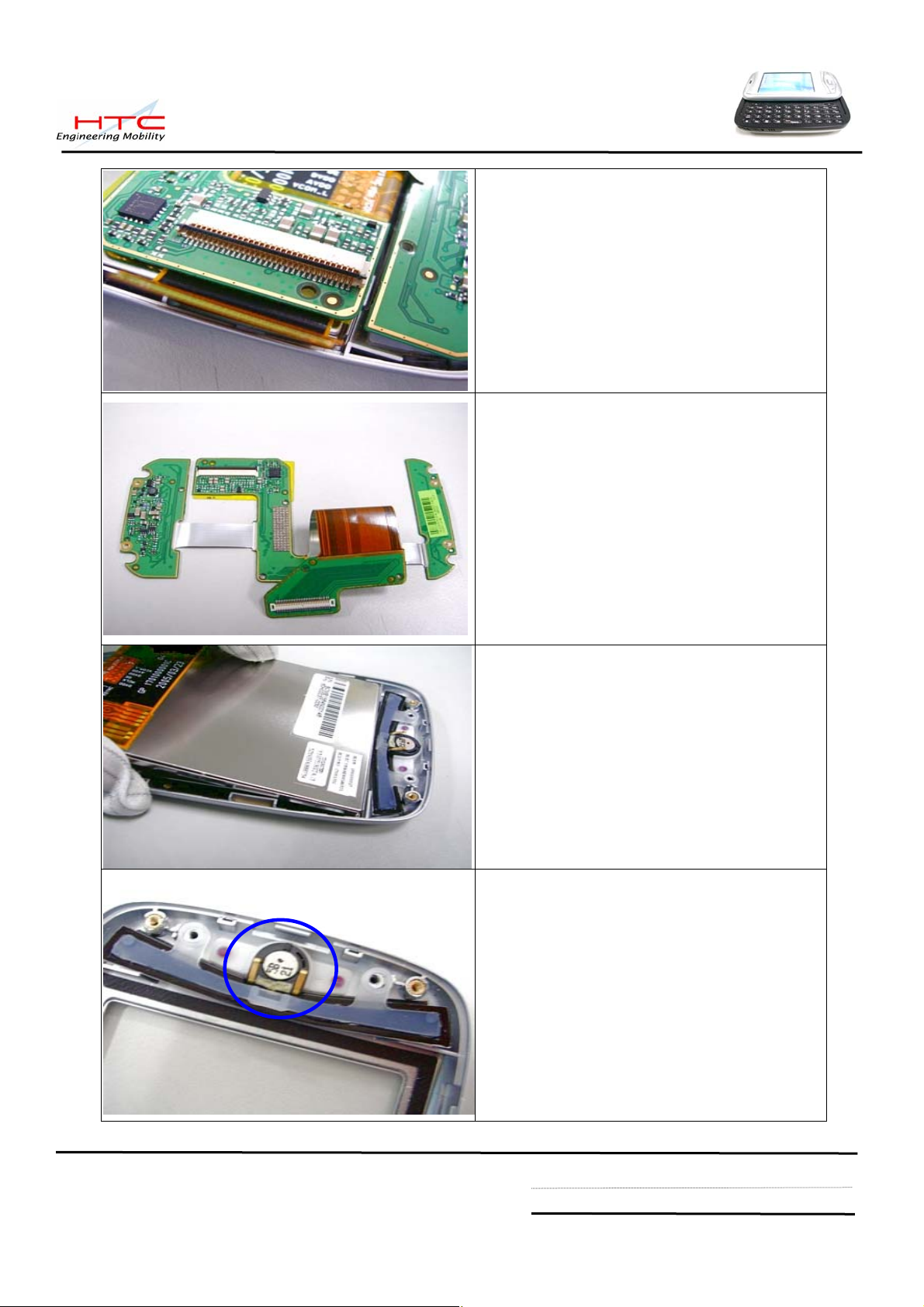
Disconnect LCM FPC cable
Disassembly Rigid-Flex Board
Disassembly LCM from LCM Bezel
Disassembly Receiver
HTC confidential
© 2001, HTC Corporation. All rights reserved. TOTAL 92 CONT.ON. 25 PAGE NO. 24
Page 25

Disassembly AP keypad and Navigation
keypad
Disassembly process is done
The Unit Disassembly is done
HTC confidential
© 2001, HTC Corporation. All rights reserved. TOTAL 92 CONT.ON. 26 PAGE NO. 25
Page 26

5.2 Assembling
Make sure sponges and Mylar, Gasket,…
are stuck in the main board
1. 76H01061-00M * 1
2. 72H01048-00M * 1
3. 72H01049-00M * 1
4. 72H01065-00M * 2
Assembly AP keypad to LCM bezel
Assembly Receiver to LCM Bezel
Assembly Navigation keypad to LCM bezel
HTC confidential
© 2001, HTC Corporation. All rights reserved. TOTAL 92 CONT.ON. 27 PAGE NO. 26
Page 27
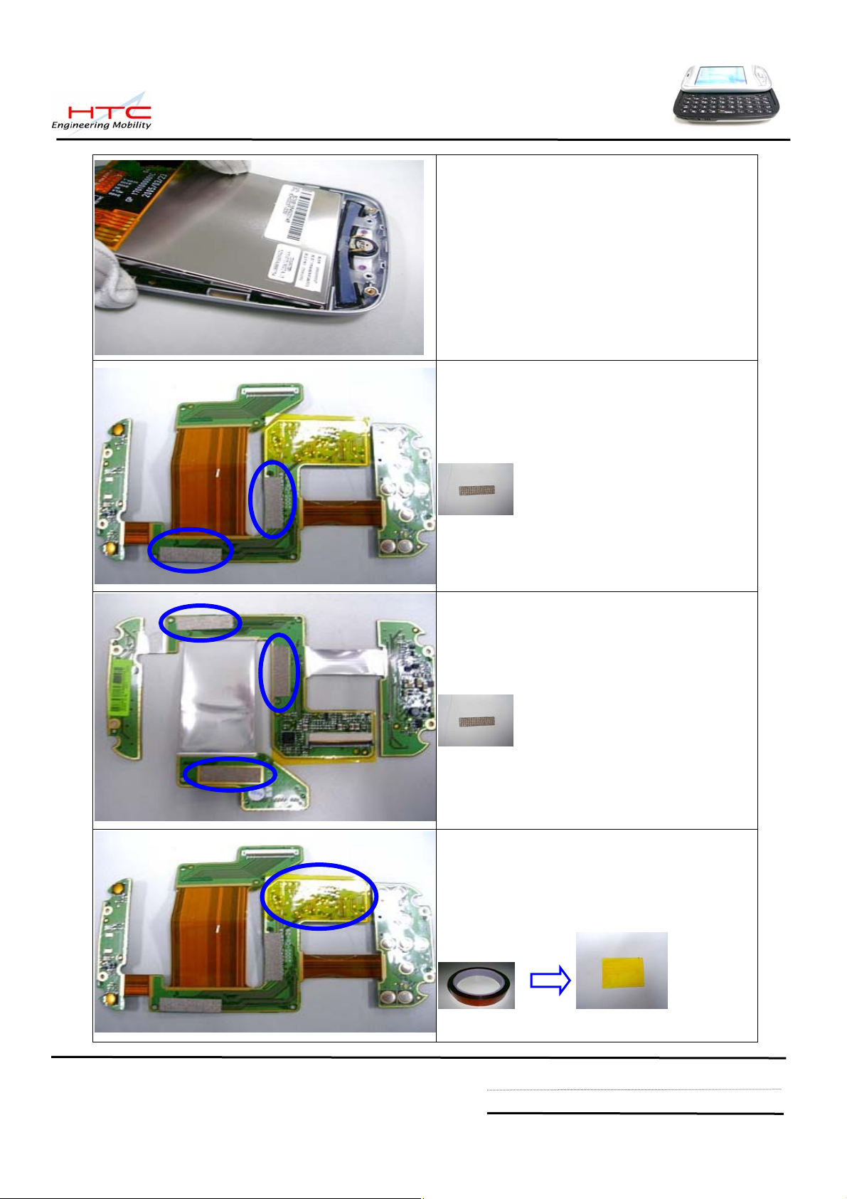
Assembly LCM to LCM Bezel
Top site – Rigid-Flex BD
Check and make sure following Gasket
have been stick on the Rigid-Flex BD
Gasket * 2; p/n :72H01135-00M
Back site – Rigid-Flex BD
Stick 3 gaskets for Rigid-Flex BD
Gasket * 3; p/n :72H01135-00M
Stick anti-short tape * 1 ;
p/n: 76H01036-00M
HTC confidential
© 2001, HTC Corporation. All rights reserved. TOTAL 92 CONT.ON. 28 PAGE NO. 27
Page 28
Install 2 screws to fix top side of Rigid-Flex
Board
Torque : 0.6 +- 0.05 kgf-cm
Install 2 screws to fix bottom side of
Rigid-Flex Board
Torque : 0.6 +- 0.05 kgf-cm
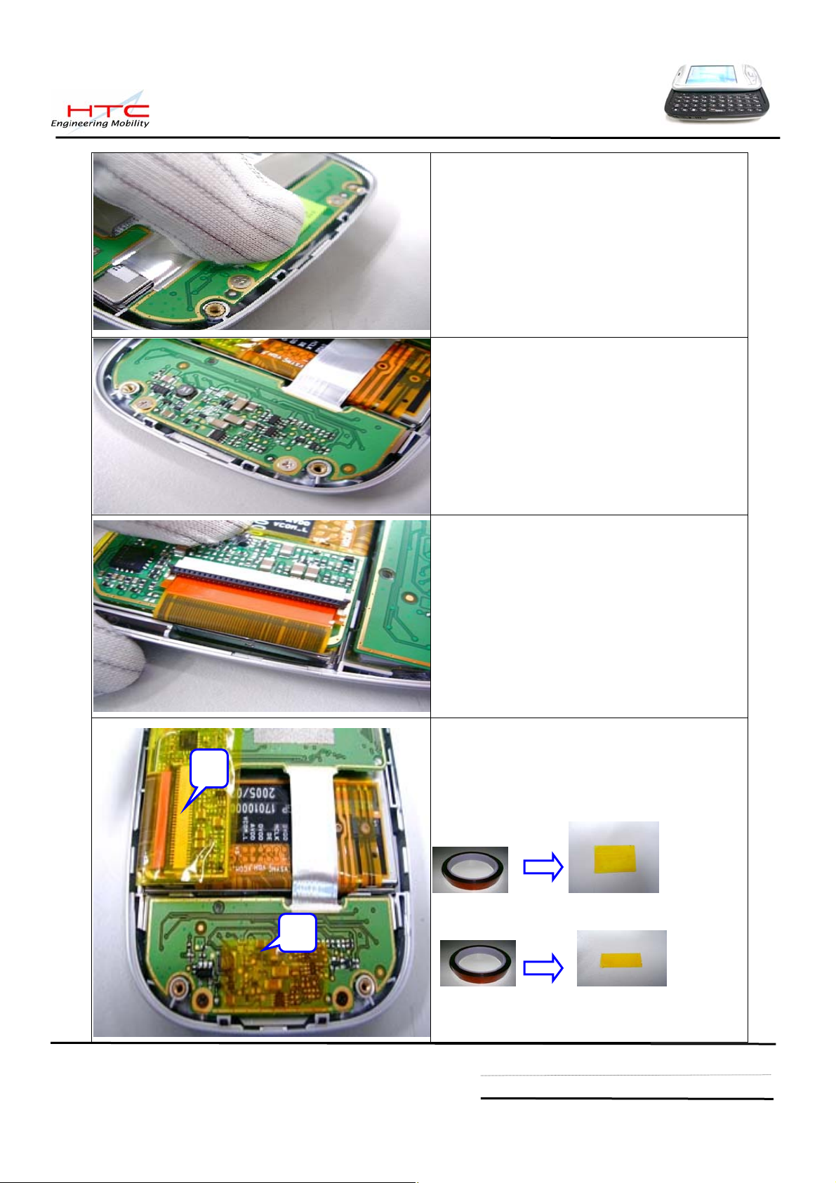
Connect LCM FPC cable to Rigid-Flex board
Once the Rigid-Flex BD is assembled,
1
Please stick 2 anti-short tapes
1. Anti-short tape for LCM connector * 1
p/n: 76H01036-00M
2. anti-short tape for Navi key * 1
2
HTC confidential
© 2001, HTC Corporation. All rights reserved. TOTAL 92 CONT.ON. 29 PAGE NO. 28
Page 29

Assembly LCM housing
Use finger and thumb to press the hook
Make sure no gap
Install 4 screws
Torque : 0.8 +- 0.05 kgf-cm
HTC confidential
© 2001, HTC Corporation. All rights reserved. TOTAL 92 CONT.ON. 30 PAGE NO. 29
Page 30

Shift the slide pillar in the place
Assembly Qwerty keypad to keypad bezel
Assembly FPC keyboard
Install 8 screws to fix keyboard with keypad
bezel
Torque : 0.55 +- 0.05 kgf-cm ( low spin power)
HTC confidential
© 2001, HTC Corporation. All rights reserved. TOTAL 92 CONT.ON. 31 PAGE NO. 30
Page 31

Assembly the Keypad bezel to LCM housing
Install 4 screws on both sides
Torque : 1.0 +- 0.08 kgf-cm
Shift the position as left picture
Assembly Microphone rubber
HTC confidential
© 2001, HTC Corporation. All rights reserved. TOTAL 92 CONT.ON. 32 PAGE NO. 31
Page 32

Stick a tape to fix microphone rubber
Connect FPC cable
Assembly main board to keypad bezel
Make sure mini-USB connector and Audio jack is in place
HTC confidential
© 2001, HTC Corporation. All rights reserved. TOTAL 92 CONT.ON. 33 PAGE NO. 32
Page 33

Take card the volume control switch while put
the main board into the keypad bezel
2
4
1 3
Following need to be assembly
1. Keyboard FPC cable
2. Camera
3. Speaker
4. Speaker
Stick an tape to fix the Keyboard cable
p/n: 76H01138-00M
Assembly flash-light module to keypad
housing
HTC confidential
© 2001, HTC Corporation. All rights reserved. TOTAL 92 CONT.ON. 34 PAGE NO. 33
Page 34

Assembly Vibrator to keypad housing
Assembly keypad housing
From bottom to top side while assembly
Use finger and thumb to press the hook
HTC confidential
© 2001, HTC Corporation. All rights reserved. TOTAL 92 CONT.ON. 35 PAGE NO. 34
Page 35

Put strap holder in the position
Install 4 screws
Torque : 1.1 +- 0.05 kgf-cm
Assembly Antenna cover, two hooks must be
paired first
Push the Antenna cover from top side
HTC confidential
© 2001, HTC Corporation. All rights reserved. TOTAL 92 CONT.ON. 36 PAGE NO. 35
Page 36

Use both thumbs to press the Antenna cover
Put the Battery into its place.
Warning: To reduce risk of fire or burns,
do not disassemble, crush, puncture, short
external contacts, or dispose of in fire or
water. Replace only with specified batteries.
Recycle or dispose of used batteries properly
Assembly battery cover.
Assembly process is done
Now The unit is ready for performing TEST.
The Unit assembly is done and ready for further tests.
HTC confidential
© 2001, HTC Corporation. All rights reserved. TOTAL 92 CONT.ON. 37 PAGE NO. 36
Page 37

5.3 Notification once performing Golden cap replacement
If you are authorized by HTC for board level component replacement, and if you perform M/B
replacement, must take care for following notices:
Caution: Golden cap is easy to be damaged during board level repair, if you need to do board level
repair, please follow the detail instruction as follows
G/C
Fuse
A/J
Please remove the G/C First before
replacing following component
No HTC P/N Description Location
1 36H00301-00M Fuse,PTC,1.5A PTC1
2 36H00305-00M Audio Jack ACON1
3 75H00379-00M Mini USB CON7
Criteria of soldering
*.The temperature of Solder Iron must be under
350°c
*.The heating time of Solder Iron must be under 5
seconds
*.Solder iron can not have contact with Golden
capacitor during soldering period, please
prevent the solder iron contact to body of
Golden capacitor.
Once above indicated conpoment is
replaced, please replace a new G/C to
main board, NOT ALLOW to re-use
the original unsoldered G/C.
M/U
HTC confidential
© 2001, HTC Corporation. All rights reserved. TOTAL 92 CONT.ON. 38 PAGE NO. 37
Page 38

5.4 Notification once performing M//B replacement
If you are authorized by HTC for board level component replacement, and if you perform M/B
replacement, must take care for following notice:
Warranty Seal (Security Label)
Be sure to apply new Warranty seal once the
unit has been repaired before sending back to
customer.
Stuck position: under Antenna cover as left
photo
Liquid Damage label (Water Indicator)
Be sure to apply new
once the unit has been repaired before
sending back to customer.
Stuck position: under SIM connector as left
photo
liquid damage label
In case of MB replacement, since the IMEI
has to follow new MB IMEI, repair site is
required to re-print Regulatory label to change
IMEI no, but Serial no. must remain
unchanged.
Label format : according customer request,
detail please refer to section 3 - labeling
HTC confidential
© 2001, HTC Corporation. All rights reserved. TOTAL 92 CONT.ON. 39 PAGE NO. 38
Page 39

5.5 Notification once performing LCM replacement
There are 2 sources of LCM and Rigid-Flex board, the 1st source of LCM must match that of 1st source
of Rigid-Flex board. The same rule is applied for 2
nd
source of LCM and Rigid-Flex board as well. Repair
center is requested to check original used component before replacing LCM or Rigid-Flex board,
For example below:
Original used LCM is 1
st
source of 60H00032-00 and verified result is fail, Must be replaced with
same p/n 60H00032-00, The match table is as follows.
80H00418-00 to match with 60H00032-00 only (Samsung LCM)
80H00418-01 to match with 60H00037-00M only (Toppoly LCM)
1st source
2nd source
80H00418-00
(51H10045-00M)
80H00418-01
(51H10045-01M)
Rigid-Flex Board ASSY,
for Samsung LCM
Rigid-Flex Board ASSY,
for Toppoly LCM
Check LCM p/n:
1st source: 60H00032-00, Samsung LCM
2nd source: 60H00037-00M, Toppoly LCM
Check Rigid-Flex Board p/n:
60H00032-00
LCD Module,
Samsung
LCD Module,
60H00037-00M
Toppoly,
1st source: 80H00418-00 (51H10045-00M)
for Samsung LCM(60H00032-00M)
nd
2
source: 80H00418-01 (51H10045-01M)
for Toppoly LCM(60H00037-00M)
HTC confidential
© 2001, HTC Corporation. All rights reserved. TOTAL 92 CONT.ON. 40 PAGE NO. 39
Page 40

5.6 Notification once performing Rigid-Flex board replacement
There are some isolation tape are stuck in the rigid-flex board, repair center is requested to
follow below process once performing rigid-flex board replacement.
80H00418-00 = 51H10045-00M (Rigid-flex BD) + 72H01135-00M(Gasket* 5) for Samsung LCM
80H00418-01 = 51H10045-01M (Rigid-flex BD)+ 72H01135-00M (Gasket* 5) for Toppoly LCM
Top site – Rigid-Flex BD
Make sure there are 2 gaskets stuck on the
Rigid-Flex BD then stick an isolation tape
1. gasket * 2; p/n :72H01135-00M
2. Isolation tape * 1 ; p/n: 76H01036-00M
Back site – Rigid-Flex BD
Make sure there are 3 gaskets stuck on the
Rigid-Flex BD
Stick 3 gaskets for Rigid-Flex BD
1. gasket * 3; p/n :72H01135-00M
Back site – Rigid-Flex BD
1
Once the Rigid-Flex BD is assembled,
Please stick 2 isolation tapes
1. Isolation tape for LCM connector * 1
p/n: 76H01036-00M
2
2. Isolation tape for Navi key * 1
HTC confidential
© 2001, HTC Corporation. All rights reserved. TOTAL 92 CONT.ON. 41 PAGE NO. 40
Page 41

5.7 Notification once performing LCM housing or Keypad bezel replacement
There are 2 sources of LCM housing and Keypad bezel, the 1st source of LCM housing must match that
st
of 1
source of keypad bezel. The same rule is applied for 2nd source of LCM housing and keypad bezel
as well. Repair center is requested to check original used component before replacing LCM housing or
Keypad bezel
For example below:
Original used LCM housing is 1
p/n 74H00498-0XM of 1
st
source, The matching table and identify features are as follows
st
source of 74H00498-0XM and verified result is fail, Must replace same
74H00498-0XM to match with 74H00499-0XM only
74H00498-5XM to match with 74H00499-5XM only
st
source (Taiwan Vendor) 2nd source (Chain Vendo r- Nypro)
1
LCM housing
Hook White Black
Marked
1
74H00498-0XM 74H00498-5XM
A 、B、C 1 、 2
st
source (74H00498-0XM) 2
nd
source(74H00498-5XM)
Black hook White hook
Marked :
A/B/C
Marked:
1/2
HTC confidential
© 2001, HTC Corporation. All rights reserved. TOTAL 92 CONT.ON. 42 PAGE NO. 41
Page 42

st
source (Taiwan Vendor) 2nd source (Chain Vendo r- Nypro)
1
Keypad bezel
Marked
74H00499-0XM 74H00499-5XM
A 、B、C 1 、 2
st
1
source (74H00499-0XM) 2
Marked:
A/B/C
nd
source(74H00499-5XM)
Marked:
1/2
HTC confidential
© 2001, HTC Corporation. All rights reserved. TOTAL 92 CONT.ON. 43 PAGE NO. 42
Page 43

6. Equipment of Problem Diagnostics
6.1 List of Test Jigs
Item Name Usage Remark
USB to Mini USB Cable/Cradle For Sync test ; RUU re-flash ROM image
Special Plastic Tool For unit disassembly
Hand tools For unit disassembly
AC Adapter For battery re charge and power related tests
Earphone with Microphone For audio test
Mini SD card with diagnostic
PC or Notebook Use for Communication/Synchronization test
For Function Program designed by HTC
6.2 Hardware Requirement for PC
z O.S.: Windows 2000 above
z CPU: Pentium 166MHz or above
z Memory: 64MB~128MB
6.3 Software Requirement
z Microsoft Active Sync version 4.0 above
z Diagnostic Program loaded on Mini SD card. ( encoded by HTC)
HTC confidential
© 2001, HTC Corporation. All rights reserved. TOTAL 92 CONT.ON. 44 PAGE NO. 43
Page 44

7. Diagnostic Program
7.1. List of Test Items
No. Item Description Remark
Function Test
Auto Test All manual test tem for 1 loop
SDRAM Test RAM Check Size/Write/Read/Comparison test.
Display Test Test the LCD display quality.
LED Test Test the message LED.
Back Light Test Back light ON with in different brightness level.
Timer Check Time setting
SD Test SD card Write/Read/Write Protect test.
Vibrator Test
Key Test Test every most of button.
Flash Light Test Flash light at Video and Capture mode
Qwerty Test All the key of Qwerty Test
Slide Test Check Slide key
SPK Play Internal Speaker test.
Receiver Play Internal Receiver test.
Hst Play External headset Speaker test.
Int Rec –Spk out Internal Microphone and internal Speaker test.
Int Rec –Rev out Internal Microphone and internal Receiver test.
Int Rec –Hst out Internal Microphone and external Speaker test.
Hst Rec –Hst out External headset Microphone and external Speaker test.
View Checksum Manufacture use only
SIM information Manufacture use only
ROM to SD Manufacture use only
Run – in Test
Device info
Clear Talk time
Test the function of the vibrator.
All auto function test for option : 1/2/4/8 hrs
Check unit information, For example : Customer’s ID
1. Clear talk time recode in WinCE system information
2. Clean all PIM( personal information manage) storage
CAUTION: This item is applied for refurbishment case
only. If the unit is repaired and will send back to original
Notice :
Refurbish
ment only
customer, It is unnecessary to perform clear talk time
Diag to SD
Copy Diag program to another encoded mini SD card
HTC confidential
© 2001, HTC Corporation. All rights reserved. TOTAL 92 CONT.ON. 45 PAGE NO. 44
Page 45

7.2 Test Items Operation
How to Enter Test Mode
Caution: Diagnostic Card must match with unit’s SPL version, Detail please refer
to last page, section 14, Diagnostic card vs. unit’s SPL version
>Insert mini-SD card (with Diagnostic program pre loaded sent by HTC) into Min- SD slot
>Power on the unit. While press and hold the Capture button and Reset the unit with
stylus, release Reset button first about 1 second to enter test Mode. You will find the
HTC main page as follows
>Press Action button enter test detail item
7.3 How to execute Diag. test program:
Using navigation button -"Up" or "Down" to select the test items
Using navigation button -"Left" or "Right" to change page
Press “Action” to execute testing
Caution: Don’t format diagnostic card once you enter Win CE mode
HTC confidential
© 2001, HTC Corporation. All rights reserved. TOTAL 92 CONT.ON. 46 PAGE NO. 45
Page 46
8. Main battery Test procedure
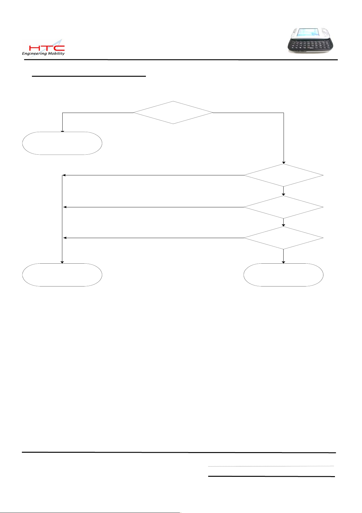
8.1: Certification flow
Replace M/B
Fail PASS
Unit current
consumption test
Fail
Fail
Fail
Whole unit
charge test
OK
Whole unit
discharge test ?
OK
Run down test ?
Battery is OKBattery is NG
OK
OK
HTC confidential
© 2001, HTC Corporation. All rights reserved. TOTAL 92 CONT.ON. 47 PAGE NO. 46
Page 47

8.2 Current consumption measurement
1. Equipment requirement
A. Power Supply (set at 4 V /1A).
B. Micro-Current Meter
(support 0.5mA ~ 1A at least).
B A
2. Fixture requirement
C. Current series jig.( with black and
red cable)
D. Cable
E. Battery with extension cable
ED C
3. Connect cable (D) to positive polarity of
power supply (A) and current meter (B)
4. Connect cable of fixture( C ) to negative
polarity of power supply (A) and current
meter (B)
Note : black cable to power supply (A)
and red cable to current meter (B)
HTC confidential
© 2001, HTC Corporation. All rights reserved. TOTAL 92 CONT.ON. 48 PAGE NO. 47
Page 48

5. Install battery fixture (E) to unit
6. Ready for testing
(Don’t turn on power at the moment)
7. Turn on power supply ( 4V)
8. Turn on current meter ( 2A)
HTC confidential
© 2001, HTC Corporation. All rights reserved. TOTAL 92 CONT.ON. 49 PAGE NO. 48
Page 49

9. Press Power button to turn on the
unit
10. In “main page”, Check phone
status, Click “Turn on flight mode”
11. Make sure all the RF function is
closed already
12. Turn off back light, the current will be
showing on current meter, this status is
so called “ idle mode” , The criteria is
as follows
<= 108 mA
Unit is still turned on but no back light
13. After idle current checked, press
power button then release soon, the
power will be off, this status is so called
“ sleep mode”
The criteria is as follows
<= 6 mA
Unit is turn off and no display
HTC confidential
© 2001, HTC Corporation. All rights reserved. TOTAL 92 CONT.ON. 50 PAGE NO. 49
Page 50

8.3 Whole unit charge and discharge test
1. Whole unit charge test
Plug in AC adapter to unit.
The charge light must be turn on, If it is failed
in charge test, replace another good battery
for double check.
2. Whole unit discharge test
Unplug AC adapter,
The charge light must be off, but the LCD
screen must still on display. If it is failed in
discharge test, replace another good battery
for double check.
HTC confidential
© 2001, HTC Corporation. All rights reserved. TOTAL 92 CONT.ON. 51 PAGE NO. 50
Page 51

8.4 Battery Performance on unit with Run Down Program
-> Copy Run Down software
“power detect” ; “model.txt” and
“ Setbacklight.dll” to SD card
-> Make sure turn off all RF function
( BT/WLAN/GSM) setting already before
executing Run down test.
-> Execute power detect
-> Check phone status, Click “Turn on
flight mode”
-> Make sure all the RF function is closed
already, the icon must be as right photo
HTC confidential
© 2001, HTC Corporation. All rights reserved. TOTAL 92 CONT.ON. 52 PAGE NO. 51
Page 52

-> Enter to SD card (Setbacklight.dll is a
hide file)
-> Execute PowerDetect
-> choose right model : Prodigy
-> Check the backlight status, please click
level 5 again even the default setting is
level 5 already. The propose is to
confirm back light 100% already
-> Default setting are
Sleep : 1 hour
Record : 2 minutes
It means the program will be turn off after
1 hour and detecting battery status by per
2 minutes
HTC confidential
© 2001, HTC Corporation. All rights reserved. TOTAL 92 CONT.ON. 53 PAGE NO. 52
Page 53

-> After one hour later the program will stop,
open the log file of PowerCap.txt. Please
check battery remaining capacity.
Check remaining percentage of battery at
time 00:00:XX
The criteria is as follows:
>=65 %
HTC confidential
© 2001, HTC Corporation. All rights reserved. TOTAL 92 CONT.ON. 54 PAGE NO. 53
Page 54

-The flow chart is as follows.
Charge battery to full
(during 4 hrs, from 0% to 100%)
Execute Rundown test
for 1 hour
No
Battery is bad
Replace main
battery
Check test result
PowerCap.txt
Capacity >=65%
Yes
Battery is Good
HTC confidential
© 2001, HTC Corporation. All rights reserved. TOTAL 92 CONT.ON. 55 PAGE NO. 54
Page 55

N
N
N
N
9. LCM Inspection Criteria ( For New LCM only)
Inspection Defects Accept Level
電氣特性
Electrical
Characteristic
Defects
單點
Single
1. 亮點
兩個相鄰點
Bright Dots
2 adjacent
三個或三個以上的相鄰點
3 or more adjacent
單點
2. 暗點
Single
Dark Dots
兩個相鄰點
2 adjacent
3. 暗或亮線
Dark or Bright lines
4. 所有可允許的點
All Allowable Dots Defects
紅點+綠點+藍點 ≦ 3
Red+ Green+ Blue ≦ 3
> 5mm.
S
0
0
總數 ≦ 2
Total Number ≦ 2
> 5mm.
S
0
0
總數 ≦3
Total Number ≦ 3
S
> 5mm.
5. 螢幕顯示區偏移傾斜
Shift and tilt of screen viewed area
刮傷, 外來物
與上蓋之四周間隙 > 0.2mm
Around gap distance the bezel > 0.2 mm
0.03 < W ≦ 0.1 (mm)
1. 刮傷
或毛屑
L ≦ 5 (mm)
Scratch
Foreign
Scratch,
≦ 2 ,
0.03 < W ≦ 0.1 (mm)
2. 毛屑(線性外來物)
Objects or Lint
未開機狀態
On power off
status
Lint (linear foreign objects)
3. 顆粒
Spots
0.3 < L ≦ 3.0 (mm)
≦ 5 ,S=15mm
0.1 < D ≦ 0.3 (mm)
≦ 4 , S=15mm
0.1 < D ≦ 0.4 (mm)
4. Fish eye on film ≦ 4 ,
牛頓環
(Newton Ring)
Limit Sample,N≦1
HTC confidential
© 2001, HTC Corporation. All rights reserved. TOTAL 92 CONT.ON. 56 PAGE NO. 55
Page 56

N
半透明物質沾污
(Semitransparent material)
不允許
(Not allowed), N≦0
5. 表面破裂
ot acceptable
Breakage on film surface
6. 全部可允許之不良點數≦10 點
Total acceptable defect quantity ≦ 10
HTC confidential
© 2001, HTC Corporation. All rights reserved. TOTAL 92 CONT.ON. 57 PAGE NO. 56
Page 57

10. RF Test
10.1 GSM function test
For RF antenna test, you need to set up your mobile tester, Antenna coupler and Shielding
box to meet HTC specification and requirement.
10.2 Hardware Requirement:
1. Mobile Tester.
2. Plane Antenna
3. Test Jig.
4. Shielding Box
5. RF golden sample
6. RF cable
10.3 RF test connection (following is a example of HTC RF test solution)
HTC confidential
© 2001, HTC Corporation. All rights reserved. TOTAL 92 CONT.ON. 58 PAGE NO. 57
Page 58

10.4 RF Antenna specification
Item
Camp @DCS Band
1
BS Originate call
2
Fast Bit Error Rate
3
Fast Bit Error Rate
4
Fast Bit Error Rate
5
6 TX Phase RMS Error
7 TX Phase Peak Error
8 TX Frequency Error
9 TX Phase RMS Error
10 TX Phase Peak Error
11 TX Frequency Error
12 TX Phase RMS Error
13 TX Phase Peak Error
Test Name
Tx level TCH 1st Download cell power Note
0 512 -75
BCH=600
0 512 -75
E-GSM 900 RECEIVER TEST
5 975 -104
5 42 -104
5 124 -104
E-GSM 900 Transmitter TEST
5 975 -104
5 975 -104
5 975 -104
5 42 -104
5 42 -104
5 42 -104
5 124 -104
5 124 -104
14 TX Frequency Error
15 Check TX Power
16 Check TX Power
17 Check TX Power
5 124 -104
5 975 -104
5 42 -104
5 124 -104
HTC confidential
© 2001, HTC Corporation. All rights reserved. TOTAL 92 CONT.ON. 59 PAGE NO. 58
Page 59

DCS 1800 Receiver Test
1
Fast Bit Error Rate 0 512 -104
2
Fast Bit Error Rate 0 698 -104
3
Fast Bit Error Rate 0 885 -104
DCS 1800 Transmitter Test
4 TX Phase RMS Error 0 512 -104
5 TX Phase Peak Error 0 512 -104
6 TX Frequency Error 0 512 -104
7 TX Phase RMS Error 0 698 -104
8 TX Phase Peak Error 0 698 -104
9 TX Frequency Error 0 698 -104
10 TX Phase RMS Error 0 885 -104
11 TX Phase Peak Error 0 885 -104
12 TX Frequency Error 0 885 -104
13 Check TX Power 0 512 -104
14 Check TX Power 0 698 -104
15 Check TX Power 0 885 -104
HTC confidential
© 2001, HTC Corporation. All rights reserved. TOTAL 92 CONT.ON. 60 PAGE NO. 59
Page 60

PCS 1900 Receiver Test
1 Fast Bit Error Rate 0 512 -104
2 Fast Bit Error Rate 0 661 -104
3 Fast Bit Error Rate 0 810 -104
PCS 1900 Transmitter Test
4 TX Phase RMS Error 0 512 -104
5 TX Phase Peak Error 0 512 -104
6 TX Frequency Error 0 512 -104
7 TX Phase RMS Error 0 661 -104
8 TX Phase Peak Error 0 661 -104
9 TX Frequency Error 0 660 -104
10 TX Phase RMS Error 0 810 -104
11 TX Phase Peak Error 0 810 -104
12 TX Frequency Error 0 810 -104
13 Check TX Power 0 512 -104
14 Check TX Power 0 661 -104
15 Check TX Power 0 810 -104
HTC confidential
© 2001, HTC Corporation. All rights reserved. TOTAL 92 CONT.ON. 61 PAGE NO. 60
Page 61

GSM 850 Receiver Test
1 Fast Bit Error Rate 5 128 -104
2 Fast Bit Error Rate 5 189 -104
3 Fast Bit Error Rate 5 251 -104
GSM 850 Transmitter Test
4 TX Phase RMS Error 5 128 -104
5 TX Phase Peak Error 5 128 -104
6 TX Frequency Error 5 128 -104
7 TX Phase RMS Error 5 189 -104
8 TX Phase Peak Error
5 189
-104
9 TX Frequency Error 5 189 -104
10 TX Phase RMS Error
11 TX Phase Peak Error
5
251 -104
5 251
-104
12 TX Frequency Error 5 251 -104
13 Check TX Power 5 128 -104
14 Check TX Power 5 189 -104
15 Check TX Power 5 251 -104
HTC confidential
© 2001, HTC Corporation. All rights reserved. TOTAL 92 CONT.ON. 62 PAGE NO. 61
Page 62

10.5 Bluetooth Function Test
->Prepare Two units with BT function, One
will be the UUT (unit under test) and the
other one will be the Host unit (Source
unit).
->Named in Owner Information for Both
devices
Here is an example:
Host device named “ Test_270’”
UUT device named “ Test_519”
-> Turn on Bluetooth for both devices
->Choose “Bluetooth Setting” for both
devices.
->Enable “Turn on Bluetooth”
->Enable “Make this device discoverable to
other devices” for both devices.
HTC confidential
© 2001, HTC Corporation. All rights reserved. TOTAL 92 CONT.ON. 63 PAGE NO. 62
Page 63

->Tap “ New Partnership…” in Host device
-> In Host device, will find the UUT device
(Test_519) and showing in the page
-> In Host device, Tap “ Test_519”
-> Tap “ NEXT”
-> In Host device, Input passkey “ 0000”
-> Tap “NEXT”
HTC confidential
© 2001, HTC Corporation. All rights reserved. TOTAL 92 CONT.ON. 64 PAGE NO. 63
Page 64
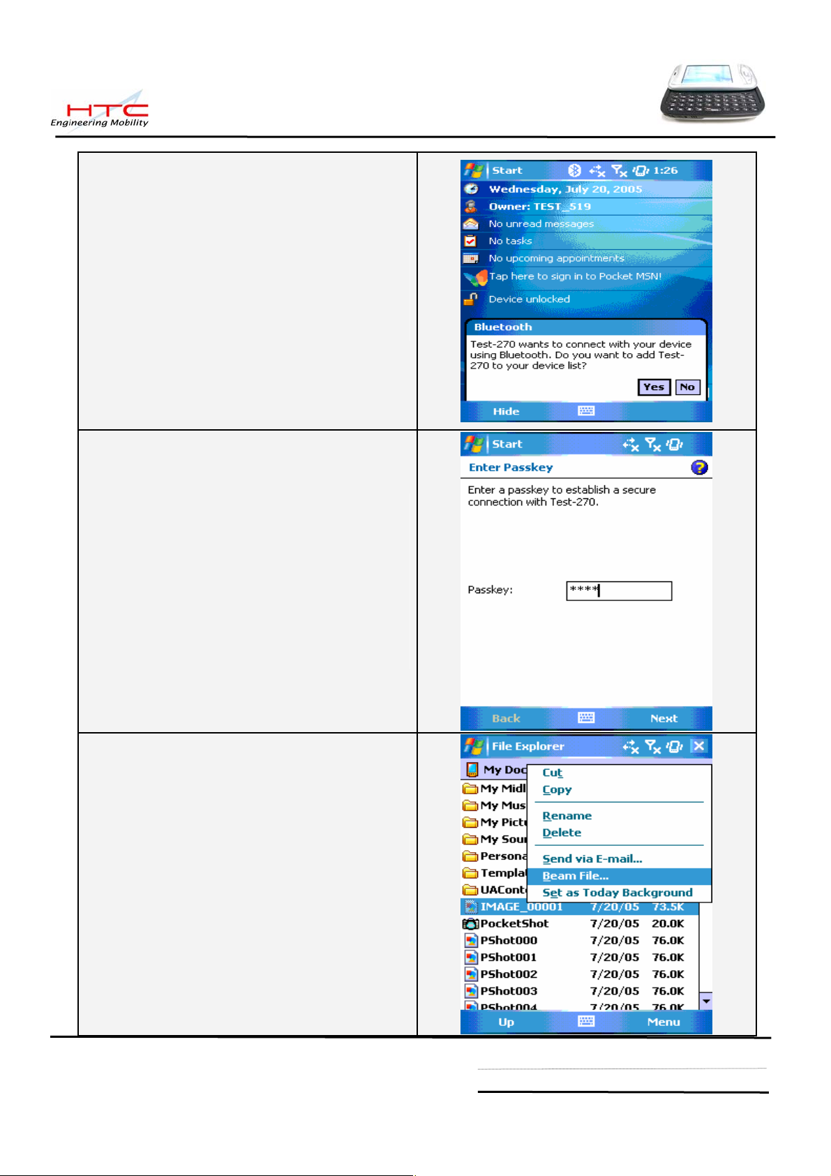
-> In UUT ( TEST_519), The Screen will
appear an message
-> Tap “YES”
-> In UUT ( TEST_519), The Screen will
appear a request of passkey
-> In UUT ( TEST_519) , Input “0000”
-> Tap “NEXT”
-> In Host device (Test_270), choose a file
( for example: Image_00001, then press
and hold the file until appear sub-icon
-> Tap “Beam file”
HTC confidential
© 2001, HTC Corporation. All rights reserved. TOTAL 92 CONT.ON. 65 PAGE NO. 64
Page 65

-> In Host device, the screen will appear
UUT “Test_519”
-> Tap UUT “Test_519”
-> In UUT(Test_519), The screen will
appear message:
Do you want to accept “ Image_0001?
-> Tap YES
->In UUT(Test_519), it must successful get
a file “ Image_00001” in the folder of My
document.
HTC confidential
© 2001, HTC Corporation. All rights reserved. TOTAL 92 CONT.ON. 66 PAGE NO. 65
Page 66

10.6 WLAN Function Test
->Enable Wireless manager
-> Turn on WLAN
->Choice AP device when multple networks
detected.
(Click Wireless manager icon) (Turn on WLAN)
->Check the symbol of connection and
power performance indicate to ensure the
wireless is turn on as well.
->Tap Start->Internet Explorer.
->Enter web address:
:http://htcscm10.htc.com.tw/SDO/
WLAN.ASP
(Choice AP device) (Check WLAN performance)
(Select Internet Explorer) (Enter web address)
HTC confidential
© 2001, HTC Corporation. All rights reserved. TOTAL 92 CONT.ON. 67 PAGE NO. 66
Page 67

->Login HTC WLAN testing web page.
->Please tap the indication at center of
screen to start download file.
->Tap “Yes” and start to download mp3 file.
->After download finished, please check
the playing status in windows media to
ensure the function is normal.
(HTC WLAN testing web) (Download file for 1Mbytes)
(File download) (Play in Windows media)
HTC confidential
© 2001, HTC Corporation. All rights reserved. TOTAL 92 CONT.ON. 68 PAGE NO. 67
Page 68

11. Firmware of OS/ Radio/Application upgrade
11.1 RUU (Rom Upgrade Utility)
OS/GSM/AP upgrade is performed via RUU download from RMAIII or customer web.
Service center is required to make the first master unit via RUU (Rom Upgrade Utility).
RUU package is able to download from HTC RMAIII
Website
http://htcscm10.htc.com.tw/rmaiii/ or customer website with some easy step.
Make sure your master unit is fully charged before starting download.
Based on encoded mechanism for locking of CID and language, service center is able
to purchase some 128 MB encoded mini-SD card from HTC for ROM image download purpose.
The following steps will lead you how to build your master unit via :
1. RUU mechanism.
2. New sample unit
Also the procedure is able to create mini-SD card for re-flash purpose, then for each repair unit,
you only need to do re-flash via mini-SD card. You could decide how many mini-SD cards you
need for this purpose depend on your needed. You can send PO to HTC for purchasing the
encoded mini-SD card, material description is as follows
“Prodigy re-flash card, 128 MB”
Caution: It is suggested to re-flash unit under boot-loader mode, once re-flash process is
not successful, please enter boot-loader mode and re-flash again.
a. Execute RUU, here is an example, actually file name and process depend on
released RUU version.
HTC confidential
© 2001, HTC Corporation. All rights reserved. TOTAL 92 CONT.ON. 69 PAGE NO. 68
Page 69

b. Following display will show on screen:
c. Type Next
HTC confidential
© 2001, HTC Corporation. All rights reserved. TOTAL 92 CONT.ON. 70 PAGE NO. 69
Page 70

d. The screen will show on display, click NEXT
e. Follow the instruction on PC and make sure Active Sync connection is established before go to
NEXT
HTC confidential
© 2001, HTC Corporation. All rights reserved. TOTAL 92 CONT.ON. 71 PAGE NO. 70
Page 71

f. Click Update
g. Click NEXT
HTC confidential
© 2001, HTC Corporation. All rights reserved. TOTAL 92 CONT.ON. 72 PAGE NO. 71
Page 72

h. Click NEXT and wait until process completed.
i. Start to re-flash unit
HTC confidential
© 2001, HTC Corporation. All rights reserved. TOTAL 92 CONT.ON. 73 PAGE NO. 72
Page 73

j. Once completed, Display will show as below in PC, and unit will be auto re-boot
Caution: if the screen in computer shows as above, the handset is still stand on re-flash
screen (100%), please wait a moment without disconnect USB cable.
Caution: if the screen is frozen after re-flash, Please try to execute Hard-reset.
HTC confidential
© 2001, HTC Corporation. All rights reserved. TOTAL 92 CONT.ON. 74 PAGE NO. 73
Page 74
11.2 Upload ROM image from master unit to HTC encoded mini-SD card
System Requirement:
-Windows 2000 above
-USB Cable or Cradle
-ActiveSync. Version 4.0 above
-MTTY.exe
-Master Unit with most updated Rom Code
-128 MB encoded mini-SD card.
Caution: The unit must have at least 70% of battery capacity before starting the re-flash process.
Charge the battery in advance if necessary.
Note: For the master unit, you could prepare it on these following ways:
- Take one from Swap unit with most update Rom Code.
- Build one first by connecting to HTC website
http://htcscm10.htc.com.tw/rmaiii/
- Customer website for OS Upgrade/ Download via RUU.
(You Only need to do this ONCE there are New RUU released)
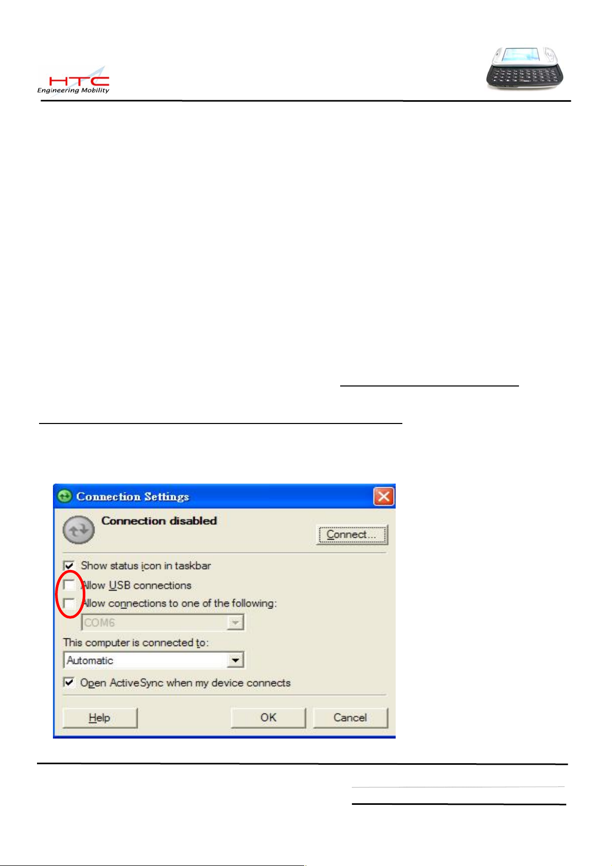
a. Uncheck USB and COM port in Connection Settings in ActiveSync if you have installed the
ActiveSync 4.0 above in your PC and make sure the USB port is available.
HTC confidential
© 2001, HTC Corporation. All rights reserved. TOTAL 92 CONT.ON. 75 PAGE NO. 74
Page 75
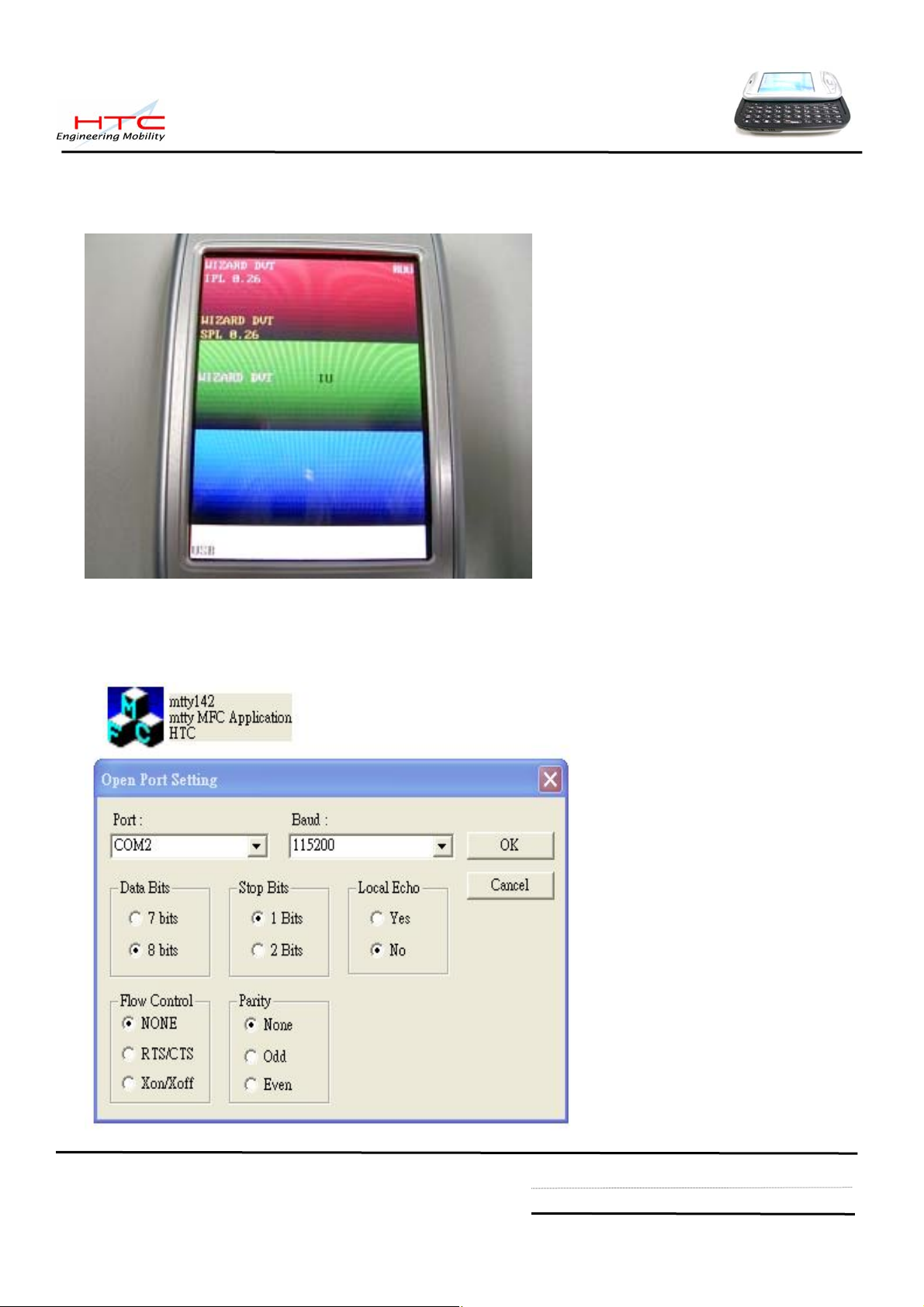
b. Set the Unit into Boot-loader Mode (While Press & Hold Capture button and Reset the units),
wait for the screen show on display
c. Connect USB cable to unit and PC, Execute MTTY.exe (V1.42 above) and set to USB Port,
Here is an example, actually display depend on MTTY.exe version.
HTC confidential
© 2001, HTC Corporation. All rights reserved. TOTAL 92 CONT.ON. 76 PAGE NO. 75
Page 76

d. Insert HTC encoded 128 MB mini-SD card into mini-SD slot
e. On the PC side, Select OK and press ENTER. Following display will show on PC
HTC confidential
© 2001, HTC Corporation. All rights reserved. TOTAL 92 CONT.ON. 77 PAGE NO. 76
Page 77

f. The prompt “Cmd>” will appear, then upload ROM Image , Type:
Cmd>r2sd all
(it means to upload ROM image code to encoded mini-SD card by typing r2sd command, note
there is a blank space between r2sd , all), then Press ENTER
The following display will be shown on PC screen …..
g. The process begins and waiting for some minutes, if process is done the screen will show
on PC.
CAUTION! DO NOT REMOVE THE USB CABLE FROM THE PC OR PDA, FAIL TO
DO SO MAY CAUSE DEVICE UNIT FAIL TO BOOT.
HTC confidential
© 2001, HTC Corporation. All rights reserved. TOTAL 92 CONT.ON. 78 PAGE NO. 77
Page 78

h. if process is done, The screen will show on unit.
Take out the mini-SD card from PDA phone and mark it according to the Language you
build for.
HTC confidential
© 2001, HTC Corporation. All rights reserved. TOTAL 92 CONT.ON. 79 PAGE NO. 78
Page 79

11.3 Use Pre-loaded mini-SD card to Re-flash Unit
a. Insert Pre-loaded mini-SD card to the unit. Please pay attention not to format the mini-SD
card.
b. Reset the unit and enter the boot-loader mode (by pressing Capture button simultaneously
and Reset the unit), Display will show message as below….
c. Follow the instruction on the unit by pressing V oice dial key (Record button) to st art re-flash.
Once process is done, the screen will be showing as below
d. Take out the mini-SD card and RESET the device (unit).
Now the upgrade procedure is done.
Caution: Due to security issue, it is not allowed to re-flash different customer ID .
HTC confidential
© 2001, HTC Corporation. All rights reserved. TOTAL 92 CONT.ON. 80 PAGE NO. 79
Page 80

12. Troubleshooting & Repair
Before repairing, please try to duplicate if the symptom exist or Customer mishandling
1-A.Main Unit Does Not Respond to Power Button
1-B.Main Unit Does Not Respond to Battery Switch
1-C.Charge light is red when plug in AC adapter
(1) Make sure the Battery is installed properly to activate the battery pack.
(2) Connect the AC Adapter, maybe the battery pack is exhaust.
(3) Check the Battery cover is close properly.
(4) Try with another battery pack.
(5) Replace battery pack if necessary.
(6) Try to enter boot loader mode, Perform Re-flash OS if successfully.
(7) CMOS Camera is not assembled properly.
(8) Check all connections including LCD FPC to Main Board. Try with another Main Board.
(9) Fuse blown .
(10) Customer abuse caused the power button fallen off
(11) Both item 9 & 10 , MB replacement is necessary unless you are authorized to do board level repair.
(12) If
Charge light is red when plug in AC adapter, it means the main battery is not charge enough and can’t power on,
You just need to continue charge unit the light become Amber.
(13) Once the defective part has been identified, verify it again with the defective part whether the
symptom could be duplicated.
2-A.Touch Panel Does Not Respond to Screen Tap
(1) Dismantle the unit, check the perimeter of Display between display Bezel and Touch Panel
surface for unusual foreign objects. Clean it, reassemble the unit and check the panel’s
function again.
(2) Check the connection of LCM FPC whether is properly conne cted.
(3) Try with another LCM.
(4) Try with another Rigid-Flex board.
(5) Try with another Main Board.
(6) Replace LCM if necessary
(7) Replace Main Board if necessary.
(8) Once the defective part has been identified, verify it again with the defective part whether the
symptom could be duplicated.
HTC confidential
© 2001, HTC Corporation. All rights reserved. TOTAL 92 CONT.ON. 81 PAGE NO. 80
Page 81

2-B.Buttons Do Not Respond
(1) Dismantle the unit, check the status of switches on the Main Board and the plastic parts of
button of the Button not responding.
(2) Try with another Main Board, rigid-Flex or keypad.
(3) Replace Main Board, rigid-Flex or keypad if necessary.
(4) Once the defective part has been identified, verify it again with the defective part whether
the symptom could be duplicated.
(5 ) Hard Reset The unit.
3-A.Unusual Vertical / Horizontal lines or partial display
(1) Check the connection of LCM FPC whether is properly connected.
(2) Try with another LCM.
(3) Try with another Rigid-Flex board
(4) Try with another Main Board.
(5) Replace LCM if necessary
(6) Replace rigid-Flex board if necessary
(7) Replace Main Board if necessary.
(8) Once the defective part has been identified, verify it again with the defective part whether the
symptom could be duplicated.
3-B.Back Light Does Not Turn ON/OFF
(1) Check the connection of FPC whether is properly connected.
(2) Try with another LCM.
(3) Try with another Rigid-Flex board
(4) Try with another Main Board.
(5) Replace LCM if necessary
(6) Replace rigid-Flex board if necessary
(7) Replace Main Board if necessary.
(8) Once the defective part has been identified, verify it again with the defective part whether the
symptom could be duplicated.
HTC confidential
© 2001, HTC Corporation. All rights reserved. TOTAL 92 CONT.ON. 82 PAGE NO. 81
Page 82

4-A.Mini-SD Card cannot be used
(1) Check whether mini-SD Card is fully inserted to the slot until you hear a click.
(2) Try with another mini-SD card and Check whether it is Write Protected.
(3) Try with another Main Board.
(4) Replace Main Board if necessary.
(5) Once the defective part has been identified, verify it again with the defective part whether the
symptom could be duplicated.
5-A.PC Connection (USB) not possible
(1) Check whether “Connection Settings” in the MS ActiveSync is properly set.
(2) Check whether it connects with other cables or cradle, customer’s cable might be damaged.
(3) Check the external appearance of the connector on the unit whether it is physically damaged.
(4) Replace Main Board if necessary.
(5) Once the defective part has been identified, verify it again with the defective part whether the
symptom could be duplicated.
5-B.Wireless Connection (GSM / GPRS / BT / WLAN) not possible
(1) Make sure the user has been contacting the Carrier for SIM Card v alidation and activation.
(2) Make sure the Wireless Connection Settings has been properly set.
(3) Make sure the SIM Card is properly inserted to the SIM compartment. Make a life call or test
it with the RF Test Station (Antenna Test).
(4) Dismantle the Main Unit and check whether the Antenna cover is properly installed.
(5) Try with another Antenna cover.
(6) Try with another Main Board if necessary.
(7) Once the defective part has been identified, verify it again with the defective part whether the
symptom could be duplicated.
HTC confidential
© 2001, HTC Corporation. All rights reserved. TOTAL 92 CONT.ON. 83 PAGE NO. 82
Page 83

5-C.IrDA Connection not possible
(1) Make sure the IrDA port settings on the Notebook or PC are properly set.
(2) Make sure the IrDA function is properly activated on the Pocket PC and on the other device.
(3) Make sure there’s no obstruction between the two devices in connection and within the distance.
(4) Check the IrDA window whether it is broken or cracked. Replace Front Bezel if necessary.
(5) Replace Main Board if necessary.
(6) Once the defective part has been identified, verify it again with the defective part whether the
symptom could be duplicated.
6-A.Main Battery does not start
(1) Make sure the Battery cover is closed properly.
(2) Connect to the AC Adapter and see if it takes charge. Also check AC Adapter condition.
(3) Check whether AC Adapter is functioning properly.
(4) Check whether the condition of Battery Charging status is correct.
(5) Dismantle the unit and check the appearance of Battery cover.
(6) Try with another Main Board or Replace Main Board if necessary.
(7) Once the defective part has been identified, verify it again with the defective part whether the
symptom could be duplicated.
.
6-B.Battery discharges quickly even after fully charged
(1) Make sure the Battery Pack takes fully charge with AC Adapter.
(2) Check whether the condition of Battery Charging status is correct.
(3) Dismantle the unit and check the appearance of Battery cover.
(4) Try with another Battery or Replace Battery if necessary
(5) Try with another Main Board or Replace Main Board if necessary.
(6) Once the defective part has been identified, verify it again with the defective part whether the
symptom could be duplicated.
HTC confidential
© 2001, HTC Corporation. All rights reserved. TOTAL 92 CONT.ON. 84 PAGE NO. 83
Page 84

7-C.Main Battery does not recharge
(1) Make sure the Battery takes fully charge with AC Adapter.
(2) Check whether the condition of Battery Charging status is correct. Charge should be done
in no more than 3 hours.
(3) Dismantle the unit and check the appearance of Battery cover.
(4) Try with another Battery or Replace Battery if necessary
(5) Try with another Main Board or Replace Main Board if necessary.
(6) Once the defective part has been identified, verify it again with the defective part whether the
symptom could be duplicated.
8-A.No Sound from Speaker or Distorted sound
(1) Check “Sound & Notifications” Settings in the unit for Sound Enabling.
(2) Make sure it’s not MUTED.
(3) Dismantle and Check whether the Speaker is properly installed (Orientation)
(4) Make sure the connection point between MB and Speaker is free from contamination or dust.
(5) Replace Speaker if necessary.
(6) Replace Main Board if necessary.
(7) Once the defective part has been identified, verify it again with the defective part whether the
symptom could be duplicated.
(8) Replace Camera if camera function was defect at the same time.
9-A.No Recorded Sound or Distorted sound
(1) Check “Sound & Notifications” Settings in the unit for Sound Enabling.
(2) Make sure it’s not MUTED.
(3) Dismantle and Check whether the Microphone is properly installed (check or missing rubber)
(4) Replace Microphone if necessary.
(5) Replace Main Board if necessary.
(6) Once the defective part has been identified, verify it again with the defective part whether the
symptom could be duplicated.
10-A.Bezel, Housing Cosmetic damage
(1) Unless it is for Refurbishment, all Bezel, housing replacement due to cosmetic damage shall treat
as out of warranty
HTC confidential
© 2001, HTC Corporation. All rights reserved. TOTAL 92 CONT.ON. 85 PAGE NO. 84
Page 85

13. Spare part list
13.1 Unit spare part list
HTC confidential
© 2001, HTC Corporation. All rights reserved. TOTAL 92 CONT.ON. 86 PAGE NO. 85
Page 86

HTC confidential
© 2001, HTC Corporation. All rights reserved. TOTAL 92 CONT.ON. 87 PAGE NO. 86
Page 87

14.2 Board Level Spare Part List
HTC confidential
© 2001, HTC Corporation. All rights reserved. TOTAL 92 CONT.ON. 88 PAGE NO. 87
Page 88

14. Appendix
A. Customer, Retailer Misjudgment
Before attempt repairing the unit, make sure the type of reported failure could be clearly
reproduced; otherwise, check with the customer or distributor once again to identify the problem
correctly. The following are failure symptoms that are typical by misjudgment
No. Item Possibility
1
2 Battery discharges
No Power even the
power button is pressed
quickly
charged
Main Battery low power exhausted.
While Back Light is turned OFF, the surrounding lighting will be
reflected on the panel and in a dim location, it looks like the unit is
turned OFF.
According to the Power Management settings, the units will be
switched OFF automatically.
The battery life depends on the devices being used in mini-SD
Card Slot, and frequency of use of the Back light. These
functions consume a lot of energy.
Operating with front light ON, or using high energy consumption
devices such as mini-SD Memory Card will drain out the battery
pack faster.
Using AC adapter that is NOT supplied with the unit. 3 Battery cannot be
Charging the battery while operating the unit with heavy loadings
could cause the temperature inside the unit to build up which
could cause the unit stop charging. At this moment, the LED
indicator will flash Yellow to notify user that the charging has
been stopped. Or the temperature is extremely low will also stop
charging.
Since the extreme high or low temperature will cause the battery
to discharge quickly, it has been designed to cut battery charge
below 0℃ and above 35~40℃ to protect the battery pack.
4 Cannot make
communications via
mobile phones through
exclusive cable.
If the unit could pass the test with Loop back Interface card, the
possibility of unit malfunction becomes low. Then the following
items could be the reason of problem such as location, timing,
signal strength, service provider’s mixed up, or problem with the
mobile itself. Or could be incompatibility issue.
HTC confidential
© 2001, HTC Corporation. All rights reserved. TOTAL 92 CONT.ON. 89 PAGE NO. 88
Page 89

Cards which are not being pre-formatted. 5 Cannot use mini-SD
Memory Card
6 Black or White dot on
the screen.
Program Buttons are
not reacting.
8 Front Light dim, cannot
turn ON, or shuts OFF
automatically.
9 Cannot playback music,
No sound or volume is
low.
10 Cannot execute
installed application
Card not inserted completely, or bad contact between connector
contacts.
For LCD panel’s normal behavior , it is hard to find a p anel without
any bad pixel. Once the numbers of dots and the distance
between them are within the specifications, it is allowed.
Could be wrong operation. 7 Touch Screen or
Screen not properly aligned with the stylus calibration.
Check the Front Light settings in Power Management settings
When Battery low, the music playback becomes difficult and the
volume could become lower.
Could be an incompatible software
programs
11 Operation is slow in
response
12 Hang up
13 System Memory is
enough, but is shows
insufficient.
Could be insufficient memory. Check amount of system memory.
Software being used sometimes is not fully compatible with the
system.
Execute many application programs simultaneously
Software that requires big amount of memory spaces or the
system memory is low or the files being used is fragmented.
Software that requires big amount of memory spaces or the
system memory is low or the files being used is fragmented.
*Note: Nevertheless, the above symptoms could be solved by a warm- reset or hard- reset,
make sure the warm /hard reset has been executed and try to reproduce the
symptom reported.
HTC confidential
© 2001, HTC Corporation. All rights reserved. TOTAL 92 CONT.ON. 90 PAGE NO. 89
Page 90

B. How to perform Warm reset and Hard reset
Comm
manager button
Warm-reset : Reset the unit by pressing reset button.
Hard reset: Press and hold Comm manager button + Record button, then Reset the unit.
Press Send Key to turn back manufacture default setting
Record button
Reset button
C. To remove main battery, it is requested that turn off the unit before removing main
battery
D. It is suggested to re-flash unit under boot-loader mode, once re-flash process is not successful,
please enter boot-loader mode and re-flash again.
HTC confidential
© 2001, HTC Corporation. All rights reserved. TOTAL 92 CONT.ON. 91 PAGE NO. 90
Page 91

E. If unit hang on 100% while using RUU re-flash, the screen in computer
shows “Congratulation”, the handset is still stand on re-flash screen (100%) as below, please
wait a moment without disconnect USB cable.
F. If the screen is frozen after re-flash done, Please try to execute Hard-reset.
G. If the unit can’t turn on, Please try following step to check
1. Plug-in AC adapter, press power button
2. If it is still not working, Try to enter boot-loader
3. If it is still not working, try to execute hard-reset.
4. If it is still not working, replace another good battery to try again,
4. If it is still not working, try to check Fuse on the main board, make sure the
component circuit can’t be Open
H. Please pay attention that following component with compatible request,
Please refer to section 5.5 and 5.7 for detail.
1. LCM + rigid-flex board
2. LCM housing+ Keypad bezel
HTC confidential
© 2001, HTC Corporation. All rights reserved. TOTAL 92 CONT.ON. 92 PAGE NO. 91
Page 92

I. There are two types diagnostic card, the purpose is to support different SPL version,
One is supported unit’s SPL version under V1.03, another one is supported unit’s
SPL version beyond V1.05 above. Both cards will provide to repair center, In order
to identify card type vs. SPL version, We marked “ SPL 1.05” on the label of
diagnostic card. If your on hand diagnostic card can not enter diagnostic mode.
Please check unit’s SPL version, The match table is as follows.
Card’s type Marked SPL version Program Version
Support SPL
V1.03 below
Support SPL
V1.05 above
Differential
description
If the card support SPL
V1.05 above, marked
”
SPL 1.05”
on the label
In boot-loader mode, The
SPL version is different
Program version is no
different
HTC confidential
© 2001, HTC Corporation. All rights reserved. TOTAL 92 CONT.ON. F PAGE NO. 92
 Loading...