

Page 1
EN
MANUAL
MANUAL
HTC D60
Translation of manual from original language
Page 2
Page 3

HTC D60
Contact information
HTC Sweden AB Box 69
SE-614 22 Söderköping, Sweden Tel: +46 (0) 121-294 00
Fax: +46 (0) 121-152 12
You can nd addresses for our retailers and service partners on our website:
www.htc-oorsystems.com
Always specify the model and serial number when asking questions about your machine.
Trademarks
HTC is a trademark owned by HTC Sweden AB. Other names and products mentioned in this manual may be registered trademarks owned by the relevant companies.
© 2017 HTC Sweden AB. All rights reserved.
3
www.htc-oorsystems.com
V 1.0
Page 4

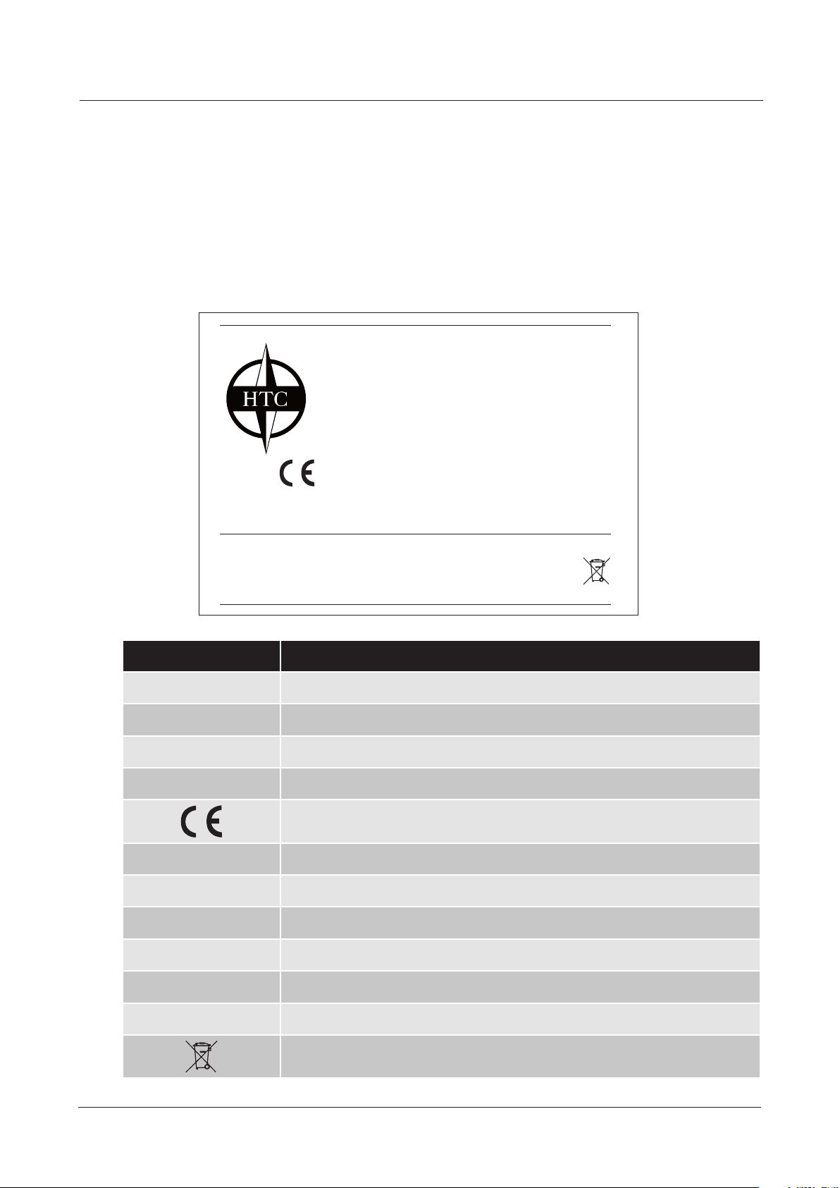
EC Declaration of conformity
Manufacturer: HTC Sweden AB
Box 69
SE-614 22 Söderköping, Sweden
+46 (0)121-29400
Type of equipment: Dust extractor
Make: HTC
Model: HTC D60
Year of manufacture: See machine name plate
Serial number: See machine name plate
Original of the EC declaration of conformity (Swedish).
Other languages are translations of the original of the EC declaration of conformity.
HTC D60
Söderköping 21.11.2017
Peter Lundgren
Development Manager
HTC Sweden AB
Björn Jeansson
Production Manager
HTC Sweden AB
www.htc-oorsystems.comV 1.0
4
Page 5

HTC D60
1. Standards
As the manufacturer, we hereby declare under our sole responsibility that the above product with
serial numbers from 2017 onward conforms to the applicable regulations in:
Standard Description
60335-1
60335-2-69
UL73 UL STANDARD FOR SAFETY MOTOR-OPERATED APPLIANCES
CAN/CSA
E60335-2-69-01 R2010,
DIRECTIVE 2014/30/EU Electromagnetic Compatibility (EMC) Directive
DIRECTIVE 2014/35/EU The Low Voltage Directive (LVD)
ISO 3746:2010
ISO 11203:2010 Acoustics -- Noise emitted by machinery and equipment
This product was CE marked in 2017.
The technical documentation is available from the manufacturer.
Houshold and similar electrical appliances - Safety - Part 1: General requirements
Household and similar electrical appliances - Safety - Part 2-69: Particular
requirements for wet and dry vacuum cleaners, including power brush, for
commercial use
Safety of Household and Similar Electrical Appliances - Part 2: Particular
Requirements for Wet and Dry Vacuum Cleaners, Including Power Brush,
for Industrial and Commercial Use (Adopted CEI/IEC 60335-2-69:1997,
second edition, 1997-02, including Amendment 1:2000, with Canadian deviations)
Acoustics -- Determination of sound power levels and sound energy levels
of noise sources using sound pressure
5
www.htc-oorsystems.com
V 1.0
Page 6

HTC D60
Table of contents
1. Standards 5
2. Introduction 7
2.1 General information 7
2.2 Liability 7
2.3 Manual 7
2.4 Machine name plate 8
3. Machine description 9
3.1 General information 9
3.2 Machine overview 10
4. Transport & storage 11
4.1 Handling and storage 11
4.2 Transport & lifting 11
5. Operation 12
5.1 Safety 12
5.2 General information 12
5.3 Various positions of the pre-separator & dust extractor 12
5.4 Control panel 13
5.5 Display use menu 14
5.6 Dust ltration 15
5.7 Filter cleaning 17
5.8 Replacing the dust bag 18
5.9 Display information menu 19
6. Accessories 20
6.1 Automatic lter cleaning 20
6.2 Remote control 21
7. Maintenance 22
7.1 General information 22
7.2 Cleaning the dust extractor 22
7.3 Daily maintenance 22
7.4 Weekly maintenance 23
7.5 Filter replacement 24
7.6 Control cabinet 25
8. Service 26
8.1 Repairs 26
8.2 Spare parts 26
8.3 Motor protection 26
8.4 Function checks 27
9. Troubleshooting 28
9.1 Warnings and error messages 29
10. Technical data 31
11. Environment 33
www.htc-oorsystems.comV 1.0
6
Page 7
HTC D60
2. Introduction
2.1 General information
Together with HTC's oor grinders, HTC's dust extractor is designed to create as dust-free environment as possible in conjunction with the dry grinding of stone and concrete oors. The dust sucked
up is collected in, for example, a bag system.
Read the manual carefully so that you know how to use and maintain the dust extractor before using
it. Contact your local retailer for further information. For contact information, see Contact Information
at the start of the manual.
2.2 Liability
Even though every effort has been made to make this manual as complete and accurate as possible, we bear no responsibility for incorrect or missing information. HTC reserves the right to change
descriptions in this manual without giving prior notice.
This manual is protected by the Copyright Act and no part of it may be copied or used in any other
way without the written approval of HTC.
2.3 Manual
In addition to general functions, this manual contains information on areas of use and care of the dust
extractor.
Safety Instructions – Explanation of Symbols
The following symbols are used in the document to indicate where special attention is needed.
Warning!
This symbol means Warning! and indicates a risk of personal injury or material
damage in the event of incorrect use of the dust extractor. If you see this symbol
next to a section of text, you must be particularly careful when reading through
the text and not carry out any stages of which you are unsure. This is for your own
and other users’ safety and to avoid damage to the dust extractor.
Note!
This symbol means Note! and indicates a potential risk of material damage in
the event of incorrect use of the dust extractor. If you see this symbol next to a
section of text, you must be particularly careful when reading through the text and
must not carry out any stages of which you are unsure. This is to avoid damage to
the dust extractor.
Tip!
This symbol means Tip! You can get tips and advice on ways to make operating
your dust extractor easier, and ways to avoid wear. When you see this symbol you
should read the accompanying text to facilitate your work and prolong the service
life of the dust extractor.
7
www.htc-oorsystems.com
V 1.0
Page 8
2.4 Machine name plate
The machine name plate provides the following information. The model and serial number must be
specied when ordering spare parts for the machine.
HTC D60
Model
Part no :
Serial no
MFG Date
Voltage :
Rated Current :
Power :
HTC Sweden AB
P.O Box 69. SE-614 22 Söderköping. Sweden
Phone +46 (0)121 294 00 Fax +46 (0)121 152 12
Internet www.htc-floorsystems.com
Name Description
Model Model
Part no Part no
Serial no Serial no
:
:
:
Frequency :
Weight :
Enclosure :
Made in Sweden
MFG date MFG date
Approved standards. Only one example is shown here, the machine name
plate shows the correct approved standards. Also see standards page 5
Voltage Voltage (VAC)
Rated current Rated current (A)
Power Power (kW/hp)
Frequency Frequency (Hz)
Weight Weight (kg/Ibs)
Enclosure Enclosure
Recycling. See Recycling page 33
www.htc-oorsystems.comV 1.0
8
Page 9

HTC D60
3. Machine description
3.1 General information
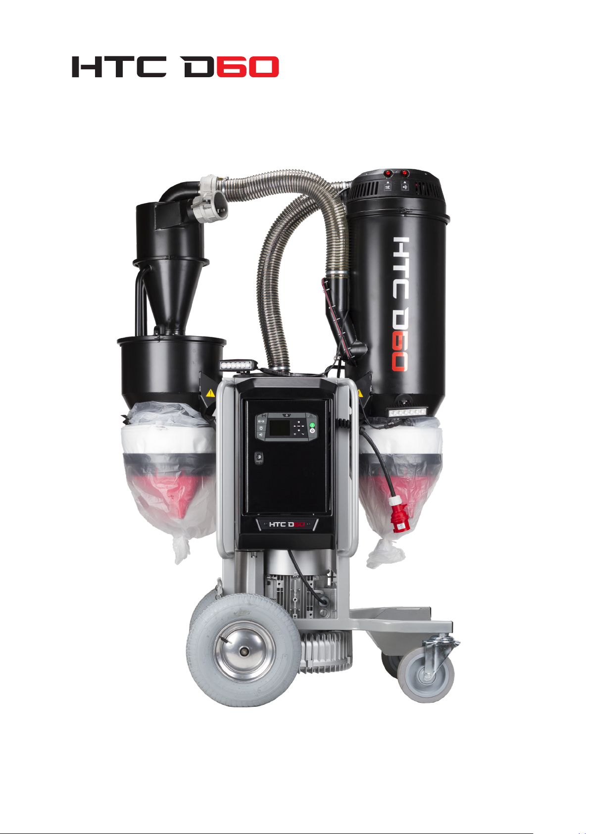
The machine is a dust extractor with an integrated pre-separator for industrial and building use
intended for the dry vacuuming of dust particles, e.g. concrete, wood, stone etc. The dust extractor
is equipped with a pre-separator, where the majority of the dust is collected instead of being sucked
into the actual vacuum cleaner, as well as a two-stage lter system, a coarse lter followed by a ne
lter.
It is also equipped with a lter cleaning system that unloads the vacuum cleaner's lter increasing the
service life and maintaining the performance of the dust extractor.
To handle the collected dust, a bag system is used on the pre-separator and dust extractor. To prevent bags from being sucked into the pre-separator or dust extractor, they are equipped with a rubber
valve that closes during operation.
The pre-separator can be raised and lowered with a simple movement and easily removed from the
chassis if necessary.
The dust extractor can also be controlled from HTC DURATIQ grinder.
9
www.htc-oorsystems.com
V 1.0
Page 10
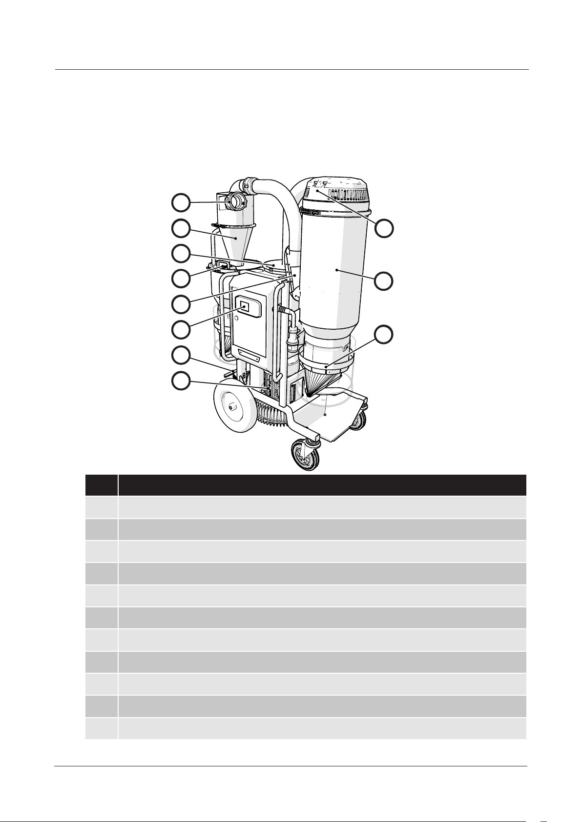
3.2 Machine overview
1
1
1
HTC D60
2
2
2
3
3
3
4
4
4
5
5
5
6
6
6
7
7
7
8
8
8
Pos. Description
1 3” camlock inlet connection
9
9
9
10
10
10
11
11
11
2 Pre-separator
3 Fine lter
4 Bypass valve
5 Inlet valve
6 Control cabinet with control panel
7 Parking brake
8 Side duct fan
9 Filter cleaning valve
10 Coarse lter container
11 Bag connection with lip valve
www.htc-oorsystems.comV 1.0
10
Page 11
HTC D60
4. Transport & storage
4.1 Handling and storage
The dust extractor should be stored in a heated, dry area when not in use.
Otherwise it may be damaged by condensation and cold.
The dust extractor's dimensions and weight are given in chapter Technical data.
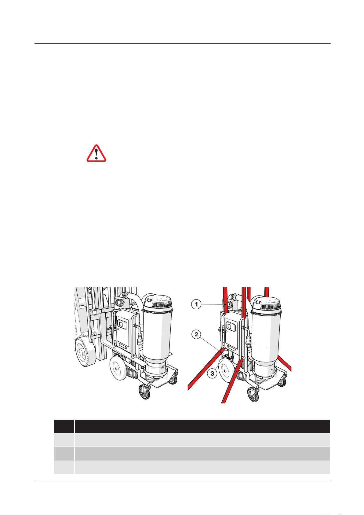
4.2 Transport & lifting
Warning!
If handled carelessly, the dust extractor can overturn and cause both
personal injury and damage to the equipment.
Always ensure that the dust extractor is emptied of dust and other particles before it is transported,
lifted or hoisted. When being moved with a forklift, always place the forks under the protection bar.
Always make sure that the dust extractor is securely anchored to its surroundings and that the parking brake is in the locked position during transport to prevent it from moving during transport. Ensure
that the securing straps, or other equipment used for anchoring during transport, are tightened in
lashing points and tensioned downwards as illustrated.
When lifting the machine, use 4 approved lifting straps at the lifting points on the machine.
When the dust extractor is to be hoisted, it must be securely anchored at two lashing points.
11
Pos. Description
1 Lifting points
2 Lashing points
3 Parking brake
www.htc-oorsystems.com
V 1.0
Page 12

5. Operation
5.1 Safety
This chapter contains all the warnings and notes that must be considered for the dust extractor.
5.2 General information
Warning!
Use protective equipment such as safety shoes, safety goggles, protective gloves, mouth mask and hearing protection.
5.3 Various positions of the pre-separator & dust extractor
Warning!
The dust extractor may only be used or repaired by personnel who
have received the requisite theoretical and practical training and who
have read the user manual.
HTC D60
Warning!
The dust extractor may only be used and moved on level surfaces.
There is a risk for crush injuries, if it should start to roll.
Tip!
Check the minimum recommended cable area before using an extension cord. You will nd the recommended cable area under Technical
Data.
The pre-separator and the dust extractor can be lowered during transport but can also be removed with a simple movement.
www.htc-oorsystems.comV 1.0
12
Page 13

HTC D60
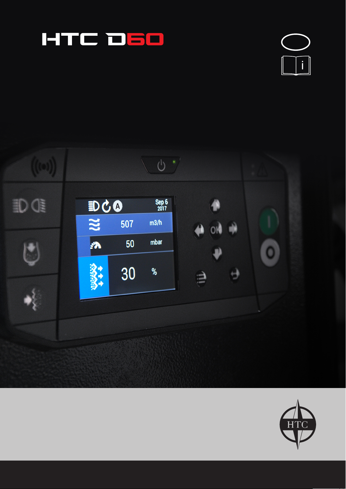
5.4 Control panel
NO. Icon Function Description
Indicates ow (m³ or cfm).
1 Display
2 On/Standby
3 Remote connection Indicates status for DURATIQ remote connection.
4 Accessory off/on Switches the accessory off and on
Dust emptying
5
6
7 Alarm / Warning
8 Menu navigation
9 Start / stop
(accessory, automat-
ic)
Filter cleaning
(accessory, automat-
ic)
Indicates pressure (total pressure mbar or in Aq).
Filter status, 0% clean lter, 100% blocked lter.
Starts up or places the machine in standby mode.
The machine wakes up when power is supplied. To place
the machine into standby mode, hold the button in. To
wake the machine press once.
Keeps the lter cleaning valve open for a time so that the
dust can fall down in the dust bags.
Runs lter cleaning (closes inlet valve and opens lter
cleaning valve) once.
Alarm, red LED. The machine cannot be operated due to
an error
Warning, yellow LED. The machine has restricted functionality.
Controls menu selection etc.
When you are not in the menus these buttons control other
functions.
Arrow up/down - switches between which value on the
screen is to be dominating (large).
Starts and stops the side duct fan.
Automatic phase switching (direction of rotation) of the
side duct fan, In the event of incorrect direction of rotation,
the side duct fan stops, the phases switch and the side
duct fan starts in the correct direction.
13
www.htc-oorsystems.com
V 1.0
Page 14

5.5 Display use menu
HTC D60
1
2
3
4
NO. Icon Function Description
Service Service
Dust emptying Dust emptying
Filter cleaning Filter cleaning
1
Direction of rotation Direction of rotation
Automatic Automatic
Lighting Lighting
Use the up or down
arrows to change
display mode.
Time and date Time and date
2 Flow
3 Pressure
4 Filter status
Indicates ow in (m³ or cfm) turns yellow when the ow is
low.
Indicates pressure (total pressure mbar or mm/Aq) turns yellow when the negative pressure is too great, suction blocked.
Risk of the motor shutting off due to overheating.
0% = Clean lter.
100% = Blocked lter, yellow bar, time to clean lter
www.htc-oorsystems.comV 1.0
14
Page 15

HTC D60
5.6 Dust ltration
Hose connection
The suction system is equipped with a 3" connector
for quick, easy and safe connection of the suction
hose between the grinding machine and dust extractor or other accessories that are to be used for
dust collection.
Pre-separator
The task of the pre-separator is to separate the
majority of the dust from the airow that passes the
machine.
The separated dust is collected in the space under
the actual pre-separator.
15
Bypass valve
To empty the space down in the bag, close the bypass valve by turning counter clockwise.
Note!
The valve should not be closed for more than a short interval, because the risk
of dust building up and blocking the pre-separator increases signicantly.
www.htc-oorsystems.com
V 1.0
Page 16

When the valve is closed, the dust falls into
the space down into the bag and if the bag is
full, it can now be replaced. When the valve is
closed, the dust is not separated but instead
continues directly to the coarse lter container. To start separating the dust, turn the valve
back.
HTC D60
When the air enters the vacuum tank, the
speed reduces, so the remaining dust in the
airow falls down into the bag. The airow
then passes a coarse lter in the coarse lter
container.
Air cleaning
To achieve a high degree of cleanliness, the
air also passes a ne lter before it passes the
side duct fan and ows out through the exhaust.
www.htc-oorsystems.comV 1.0
16
Page 17

HTC D60
5.7 Filter cleaning
NO. Icon Name Description
1 Button 1
2 Button 2 Opens the cleaning valve to clean the coarse lter
To clean the coarse lter, hold button 1 in
so that the inlet valve closes and the airow
into the coarse lter container ceases. The
side duct fan then starts to build up a greater
negative pressure.
Closes the inlet valve to build up a negative pressure in the
coarse lter container
Keep button 1 held in and then press button 2 to open the cleaning valve and clean
the coarse lter.
On the display, check that the desired
lter status is achieved after cleaning.
Otherwise, clean again.
If the lter status is above 30%,
dust is stuck in the lter and the lter
must be cleaned or replaced. See Filter
replacement 6.8
17
www.htc-oorsystems.com
V 1.0
Page 18

HTC D60
5.8 Replacing the dust bag
The dust extractor is equipped with a bag system that makes it possible to minimise dust exposure when
changing dust bags. This bag system can be ordered. Please contact your HTC retailer.
Warning!
Use protective equipment such as safety shoes, safety
goggles, protective gloves, mouth mask and hearing protection.
Place the bags in the holder and install on the container. Pull up the inner part of the bag and tighten
with the strap. Seal the lower part with a tie.
When the bag is full, pull out the bag and install two
ties and cut off the bag.
Tip!
Pull out a new length of empty bag down to the collection plate. This
is to create the best conditions for the waste to fall into the bag.
www.htc-oorsystems.comV 1.0
18
Page 19

HTC D60
5.9 Display information menu
MENUS
SETTINGS
TIME/DATE Time and date settings
Metric m³/h & mbar
UNITS
Imperial CFM & in Aq
FREQUENCY
FILTER PURGE
RADIO SYSTEM Group id
HTC SUPPORT
50Hz
60Hz
Auto Purge AUTO ON/OFF
Purge Time
Filter Status 50% — 100%
Flow
Link to webpage
(QR code and web address)
SERIAL NO.
For calculating ow
TIMER
3/5/10/15/20/30 MIN
150m³/h — 500m³/h
100cfm — 300cfm
19
SERVICE
INFORMATION
www.htc-oorsystems.com
FIRMWARE VERSION
MACHINE HOURS
COMMISIONING DATE
NEXT SERVICE
V 1.0
Page 20

6. Accessories
6.1 Automatic lter cleaning
Automatic lter cleaning automatically cleans the dust extractor's coarse lter when it becomes
blocked. This occurs by electromagnets connecting to buttons 1 and 2, whereupon the dust extractor's control panel can perform lter cleaning automatically or via a button push. Filter cleaning
occurs when one or more of the following conditions are met:
HTC D60
• Set time between lter cleans reached.
• Filter status - Standard is 100%.
Lower values giver more frequent pulses.
• Flow limit - Standard is 240 m³/h (150cfm).
Higher values give more frequent pulses.
To adjust pre-set values, see 4.9 Display information menu.
Filter cleaning from the control panel
Function button Description
Bag emptying
Filter cleaning Performs a lter cleaning cycle
Performs a slower lter clean so that the dust has
time to fall down into the bag
www.htc-oorsystems.comV 1.0
20
Page 21

HTC D60
6.2 Remote control
DURATIQ Remote Connection connects the dust extractor to a DURATIQ grinding machine.
To pair a dust extractor and DURATIQ grinding machine go to Radio System in the menu and select
the same ID in the grinding machine and dust extractor.
By doing this, the dust extractor can be controlled from a DURATIQ grinding machine and can also
send data between the devices.
2
1
Information and control from DURATIQ grinding machine
Pos. Icon Name Description
Gray icon:
Machine and vacuum cleaner are connected
Vacuum cleaners
1
Warning Yellow ashing icon in the event of warning.
Error Message
Vacuum cleaner
values
2
Change display using arrow-right or
arrow-left on the
control panel.
Red ashing icon in the event of error mes-
Vacuum cleaner is running.
to each other.
White icon:
sage.
Flow
Negative pressure
Filter status
Function button Description
21
Dust extractor Starts and stops the dust extractor
Quick press performs one lter clean
Filter cleaning
Button held in performs one dust empty
www.htc-oorsystems.com
V 1.0
Page 22

7. Maintenance
7.1 General information
We recommend regular inspection of the dust extractor.
Warning!
During maintenance and repair work, the machine must be disconnected from the mains power supply.
Warning!
Use protective equipment such as safety shoes, safety goggles,
protective gloves, mouth mask and hearing protection.
Warning!
HTC D60
Do not rinse off the dust extractor, as moisture can penetrate to the
electrical parts and damage the side duct fan.
7.2 Cleaning the dust extractor
• Vacuum the dust extractor.
• Perform lter cleaning and empty the machine of dust.
• Then clean the dust extractor after use with a damp sponge or cloth.
• Only use water.
7.3 Daily maintenance
• Check that the dust bags are intact.
• Check that the lip valves are not damaged.
• Check the lter status.
• Check that accessories such as hoses, that connect to the dust ex-
tractor are intact and do not have any cracks.
• In addition, make sure that the air ow is unobstructed and that there
are no blockages.
www.htc-oorsystems.comV 1.0
22
Page 23

HTC D60
7.4 Weekly maintenance
Check for leaks
• Place your hand over the inlet and make sure it goes up to 370mbar.
Check pre-separator
• Inspect sealing strips and surfaces for cracks or damage.
• Check for unusual dust build up.
• Also check for cracks or other irregularities.
• Adjust the quick fasteners on the pre-separator if necessary.
Check bypass valve
• Check the buttery damper can move without jamming.
• Visually check that there is no damage on the buttery damper's seal
surfaces.
Check lter cleaning valve
• Perform a normal cleaning cycle and check that the pulse valve is working
distinctly and does not leak in the closed position.
Check side duct fan
• If necessary, vacuum up any dust on visible parts of the side duct fan.
Dust around the fan can cause overheating.
• Also listen for noise from the
side duct fan.
23
www.htc-oorsystems.com
V 1.0
Page 24

7.5 Filter replacement
Warning!
The dust that is sucked up may be harmful if inhaled. Follow local
regulations and use breathing protection.
HTC D60
To check the lter, start by disconnecting the hose to the ne lter and checking in the hose connection for dust on the inside of the ne lter. In the event of dust, remove the lock ring, pull a bag
over to reduce contact with dust particles and replace the lter.
If there is dust in the ne lter, it has passed the coarse lter, which must then be replaced.
Also use a bag here to protect against dust particles.
www.htc-oorsystems.comV 1.0
24
Page 25

HTC D60
7.6 Control cabinet
2
1
4
5
3
6
7 8 9
10
No. Designation Description
1 K1
2 K2
3 Fuse 4A 24V DC
4 USB USB Port
5 PLC Control panel
Contact
(Clockwise)
Contact
(Counter clockwise)
No. Designation Description
6 K3 Contact (Black, Y)
7 K4
8 Q1 Motor protection
9 F1
10 U1 Power supply
Contact (Operation, D)
Miniature circuit
breaker
25
www.htc-oorsystems.com
V 1.0
Page 26

8. Service
8.1 Repairs
Any repairs that may be required must be carried out by a HTC Service Centre that has trained service personnel and uses HTC original parts and accessories. Contact your retailer if your machine
requires servicing. For contact information, see Contact Information at the start of the manual.
8.2 Spare parts
To ensure rapid delivery of spare parts, always specify the model, the machine's serial number and
the spare part number when ordering. Information on the model and serial number can be found on
the machine's name plate.
Information on spare part numbers can be found in the machine's spare parts list which is available to
read or print out from the accompanying digital media or HTC's website: www.htc-oorsystems.com.
Only original tools and spare parts from HTC may be used. Otherwise, neither the CE marking nor the
warranty will be valid.
8.3 Motor protection
Automatic reset of motor protection
See warning message on the screen, when it disappears, the motor protection has been reset.
HTC D60
• The motor protection trips when the motor draws too much current or if
the motor protection gets hot.
• Check whether the suction system is blocked (negative pressure is displayed on the screen).
• Disconnect the machine from the mains power supply.
• Clean the motor/control cabinet (wait a while before opening the control
cabinet).
• Close the control cabinet, connect the machine to the mains power supply and start the machine.
www.htc-oorsystems.comV 1.0
26
Page 27

HTC D60
8.4 Function checks
Check point Action
1 The dust bags Check that the bags are intact
2 The lip valves Check that they are not damaged
3 Pre-separator
4 Inlet valve
5 Cleaning valve
6 Side duct fan
Plug the inlet and check on the display that a negative pressure
is reached.
Perform the checks with the bypass valve in the open position
and in the closed position
Open the cover and check for wear on the bypass valve and
wear rubber.
Ensure that the dust extractor is off.
Remove the hose from in the inlet valve and visually inspect the
inside of the rubber membrane for wear and holes.
Start the dust extractor and hold in button 1 on the lter cleaning valve and after 3 seconds check that a negative pressure of
at least 33mbar is reached.
Switch off the suction system and remove the hose for the ne
lter.
Check for dust on the inside of the 3” hose. If dust is present,
then there is damage to the coarse lter or pilot hoses (Ø 10mm)
which can cause damage to the inlet valve's membrane.
Perform a normal cleaning cycle and check that the valve is
working distinctly and does not leak.
During normal cleaning, the display shows a max. value of ap-
prox. 280 - 330mbar.
Listen for noise.
Clean the side duct fan.
Dust around and on the fan can cause overheating.
27
7 Wheels Check for wear. Check the bearings and suspension.
8 Hose connections Check for leaks.
9 Brakes Function checks
10 Lifting points Check for cracks
11 Function of the guides
DURATIQ remote connec-
12
tion
Check all position locations and check for any wear to suspen-
sion lugs.
Check functions
Automatic lter cleaning
Lighting
www.htc-oorsystems.com
V 1.0
Page 28

9. Troubleshooting
This chapter describes some of the errors that may occur and how to deal with them. If
the error cannot be corrected, or if errors arise other than those described here, contact
your nearest retailer. See Contact Information at the front of the manual.
Symptoms Cause/Action
The dust extractor will not start.
The connected accessory does not work.
HTC D60
Check electrical connections.
Check miniature circuit breaker.
Check power supply (does the LED light?).
Check circuit board fuse. LED lights red
when the fuse has blown.
Is the symbol on the screen lit?
Check the voltage at the accessory.
Inlet valve constantly open/closed.
Filter cleaning valve not working.
The pump will not start.
Check the ow on the outputs.
Check that it works manually.
See chapter 4, Dust ltration.
Check that the membrane in the valve is intact.
Check the ow on the outputs.
Is it sealed? Check using a vacuum pump.
Is the membrane intact?
Motor protection tripped. Error message appears on screen.
Error message appears on screen.
Open-circuit motor cable.
www.htc-oorsystems.comV 1.0
28
Page 29

HTC D60
9.1 Warnings and error messages
Warnings
Warnings appear on a yellow background at the top of the screen. A warning does not usually stop
operation but the machine may have restricted functionality. Actions to ensure operation may need to
be taken. A warning can normally be minimized using the OK key and the warning is then minimized
to an icon in the icon eld. When the problem has been solved, the warning disappears.
Error Message Description
5V POWER PROBLEM Circuit board internal voltage error.
Duratiq Rmt no resp DURATIQ Remote Connection internal error.
PTC Short Circuit Short-circuit in PTC circuit
USB/PTC Overcurrent Overload on USB or PTC. Short-circuit?
Pressure sensor error.
Causes automatic pulsing to only work on time and not on lter status/
ow. Some display values also stop working, see below.
Each pressure sensor error has a three digit error code, each sensor has
its own place in the three digit code that indicates which sensor is faulty.
PSens Err 000
Sensor diff error
1xx
The values of the sensors do not correspond.
May be due to defective sensor or one of the following errors.
Error in pressure sensor P_in (pressure sensor in coarse lter container)
x#x
Error in pressure sensor P_in means lter status does not work.
Automatic pulsing only occurs on time.
Error in pressure sensor P_tot (Pressure sensor after ne lter)
Error in pressure sensor P_tot means ow meter, negative pressure
xx#
meter and lter status do not work. Automatic pulsing only occurs
on time.
Error code Designation Description
SENSOR
1
2
4
8
Example:
Error code 4 on sensor P_in and error 1 on pressure sensor P_tot, the error
message will be: PSens Err 041
SHORT TO
GND
SENSOR
SHORT TO REF
SENSOR LIMIT
HIGH
SENSOR LIMIT
LOW
Internal error on circuit board/sensor
Internal error on circuit board/sensor
The sensor gives a value that is greater
than what is normal/possible. Pressure
sensor error.
The sensor gives a value that is less than
what is considered normal.
May be due to leakage in the dust bag,
lter, seals,
pressure sensor hose etc. for example.
May also be due to a defective sensor.
29
www.htc-oorsystems.com
V 1.0
Page 30

HTC D60
Error Message
Error messages appear on a red background at the top of the screen. An error usually stops one or
more functions of the machine. Action may need to be taken to resume operation.
Error Message Description Cause
May be due to suction system stoppage
Motor Overload
Terminal xx
Overload
The overcurrent protection has
tripped.
Resets automatically when the
machine has cooled
Short circuit on terminals 1-12.
xx indicates to which terminal the short
(high negative pressure).
Low voltage.
Excessive heat.
Defective motor.
circuit applies.
Alternativ
Pump Direction
Ctrl Failure
After three failed start-up attempts three alternatives are
displayed.
The machine struggles to read
the phase sequence.
Is the
pump
direction
correct?
Yes
No
Try Again
www.htc-oorsystems.comV 1.0
30
Page 31

HTC D60
10. Technical data
The tables and pictures below show the technical data and dimensions for the dust extractor.
160601 160602 160603
HTC D60
Motor power
Current 30 A 15 A
Frequency 50Hz – 60Hz 60Hz
Voltage 180 – 240V 3
Total machine weight
50 Hz
Max. theoretical airow
60 Hz
50 Hz
Machine’s initial airow
60 Hz
Max. vacuum machine
Filter area, main lter
HEPA lter class H13
5.5kW
7.5 hp
~
380 – 415V 3
179 kg
395 Ibs
530 m³/h
312 cfm
620 m³/h
365 cfm
440 m³/h
260 cfm
500 m³/h
295 cfm
375 mbar
150 inH2O
4 m²
43 ft²
~
6.3kW
8.5 hp
440 – 480V 3
620 m³/h
365 cfm
500m³/h
295 cfm
~
31
Filter area, Hepa 13 lter
Recommended minimum cable area
Storage temperature
Working temperature
Humidity 5-90%
Sound pressure level, according to ISO
11203, measured using class 1 precision
sound level meters.
Sound power level, according to ISO 3746,
measured using class 1 precision sound
level meters.
Transmitter frequency, remote start 2.45GHz band (2400 – 2483 Mhz)
Transmitter power, remote start >1.26mW (max1dBm)
6.0 mm²
AWG10
6 m²
64.6 ft²
2.5 mm²
AWG14
-20 — +50 °C
-4 — +122 °F
-5 — +40 °C
+23 — +104 °F
82 dBA
89 dBA
www.htc-oorsystems.com
V 1.0
Page 32

HTC D60
A
C
Height and length of the dust extractor, in the operating position and transportation position.
Dimensions A B C D
1920 mm 1400 mm 1235 mm 680 mm
75.6” 55.1” 46.6” 26.8”
D
B
www.htc-oorsystems.comV 1.0
32
Page 33

HTC D60
11. Environment
HTC products are mainly constructed of recyclable metal and plastic.
The main materials used are listed below.
Machine part Material Waste management
Frame Metal, powder-coated Metal recycling
Front wheels Metal, plastic and rubber Metal recycling
Back wheels Plastic and rubber Combustible
Chassis
Dust extractor
Machine part Material Waste management
Cylinder Metal, powder-coated Metal recycling
Longopac holder Plastic, ABS Plastic recycling/Combustible
Cover Metal, powder-coated Metal recycling
Camlock Metal incl. aluminium Metal recycling 1)
Rotation joint pre-separator Plastic (nylon) Plastic recycling/Combustible
Hose Plastic (PUR) and metal wire Plastic recycling/Combustible
HEPA lter Hepa 13
Pre-lter
Metal, glass ber reinforced paper
and hot-melt adhesive
Metal, polyester and hot-melt adhesive
Metal recycling 2)
Metal recycling 2)
Electrical system
Machine part Material Waste management
Cables
Copper conductors with Neoprene
and PVC coating
Waste cable
33
Motor Metal: Steel, aluminium and copper Electronic waste
Electrical components Metal and plastic Electronic waste
1) If possible, different metals should be separated.
2) If the lter contains any hazardous substance from the grinding dust, it
must be treated as hazardous waste.
For recycling and scrapping of components, see the applicable national
regulations for each country.
www.htc-oorsystems.com
V 1.0
Page 34

Head ofce
HTC Sweden AB
Box 69
SE-614 22 Söderköping
Sweden
Street (delivery) address:
Klevvägen 7
SE-614 92 Söderköping
Sweden
Tel.: +46 (0)121-29400
Fax: +46 (0)121-15212
E-mail: info@htc-sweden.com
www.htc-oorsystems.com
HTC Floor Systems Ltd.
Unit 4 Kingston Business Park
Dunfermline Court
Maidstone Road
Kingston
Milton Keynes
MK10 0BY
United Kingdom
Tel.: +44 (0 ) 845 460 2500
Fax: +44 (0) 845 460 1500
E-mail: info@htc-europe.co.uk
www.htc-oorsystems.com
HTC Floor Systems GmbH
Hinter dem Entenpfuhl 17
65604 Elz
Deutschland
Tel.: +49 (0)6431 – 97658-0
Fax: +49 (0)6431 – 97658-22
E-Mail: order@htc-europe.de
www.htc-oorsystems.com
HTC Inc.
5617 Tazewell Pike
Knoxville, TN 37918
USA
Tel.: +1 865 689 2311
Fax: +1 865 689 3991
E-mail: info@htc-america.com
www.htc-oorsystems.com
HTC France S.A.S.
ZI Mondeville Sud
10 Rue Nicéphore Niepce
14120 Mondeville
France
Tel.: +33 (0)2 31 34 27 00
Fax: +33 (0)2 31 34 09 29
E-mail: info@htc-europe.fr
www.htc-oorsystems.com
www.htc-oorsystems.com/support
 Loading...