

Page 1

Copyright HT ITALIA 2016 Version EN 1.01 - 25/03/2016
ENGLISH
User manual
Page 2

THT32
EN - 1
Table of contents:
1 PRECAUTIONS AND SAFETY MEASURES ........................................................................... 2
1.1 During use ........................................................................................................................................ 2
1.2 After use ........................................................................................................................................... 2
2 GENERAL DESCRIPTION ....................................................................................................... 3
3 PREPARATION FOR USE ....................................................................................................... 4
3.1 Initial checks ..................................................................................................................................... 4
3.2 Instrument power supply .................................................................................................................. 4
3.3 Calibration ........................................................................................................................................ 4
3.4 Storage ............................................................................................................................................. 4
4 NOMENCLATURE .................................................................................................................... 5
4.1 Description of the instrument ........................................................................................................... 5
4.2 Description of function keys ............................................................................................................. 7
4.2.1 Menu/ key ...................................................................................................................................... 7
4.2.2 Enter key ............................................................................................................................................ 7
4.2.3 Keys , , ,................................................................................................................................ 7
4.2.4 T key (Trigger) ................................................................................................................................... 7
4.2.5 Inserting the micro SD Card .............................................................................................................. 7
5 OPERATING INSTRUCTIONS ................................................................................................. 8
5.1 Description of the main interface ...................................................................................................... 8
5.1.1 Adjusting the distance of the object in Blending Fusion function ....................................................... 8
5.2 General menu description ................................................................................................................ 9
5.2.1 Menu EMS ......................................................................................................................................... 9
5.2.2 Menu UNIT ...................................................................................................................................... 10
5.2.3 Menu MAXMIN ................................................................................................................................ 11
5.2.4 Menu PLT ........................................................................................................................................ 11
5.2.5 Menu DATE ..................................................................................................................................... 12
5.2.6 Menu MEMORY ............................................................................................................................... 13
5.2.7 Menu BGT ....................................................................................................................................... 13
5.2.8 Menu ALARM .................................................................................................................................. 14
5.2.9 Menu DISPLAY ................................................................................................................................ 15
5.2.10 Menu DIST ....................................................................................................................................... 15
5.2.11 Menu LANG ..................................................................................................................................... 16
5.2.12 Menu INFO ...................................................................................................................................... 16
5.3 Using the instrument ...................................................................................................................... 17
5.4 Transferring the images onto the PC ............................................................................................. 17
6 MAINTENANCE ...................................................................................................................... 18
6.1 General information ........................................................................................................................ 18
6.2 Recharging the internal battery ...................................................................................................... 18
6.3 Cleaning the instrument ................................................................................................................. 18
6.4 End of life ....................................................................................................................................... 18
6.5 Accessories .................................................................................................................................... 18
6.5.1 Accessories provided ....................................................................................................................... 18
7 TECHNICAL SPECIFICATIONS ............................................................................................. 19
7.1 Environment ................................................................................................................................... 19
7.1.1 Environmental conditions for use ..................................................................................................... 19
8 ASSISTANCE ......................................................................................................................... 20
8.1 Warranty conditions ........................................................................................................................ 20
8.2 Assistance ...................................................................................................................................... 20
Page 3
THT32
EN - 2
1 PRECAUTIONS AND SAFETY MEASURES
The instrument has been designed in compliance with the directives relevant to electronic
measuring instruments. For your safety and in order to prevent damaging the instrument,
please carefully follow the procedures described in this manual and read all notes
preceded by symbol with the utmost attention. Before and after carrying out the
measurements, carefully observe the following instructions:
CAUTION
Do not carry out any measurements in case gas, explosive materials or
flammables are present, or in humid or dusty environments.
Do not carry out any measurement in case you find anomalies in the
instrument such as deformation, breaks, substance leaks, absence of
display on the screen, etc.
Keep the instrument steady during any measuring operation.
Do not carry out any measurements which exceed the working and storage
temperature ranges specified in § 7.1.1.
Only the accessories provided together with the instrument will guarantee
safety standards. They must be used only if in good conditions and
replaced with identical models, when necessary.
Check that the battery is correctly inserted.
Check that the LCD display gives indications consistent with the function
selected.
Do not direct the instrument at very high intensity radiation sources (e.g. the
sun) in order to prevent damaging the IR sensor.
Prevent hits or strong vibrations in order to keep the instrument from
damage.
When bringing the instrument from a cold to a hot environment, leave it on
long enough for condensation water to evaporate.
In this manual, and on the instrument, the following symbols are used:
Warning: observe the instructions given in this manual; improper use could
damage the instrument or its components.
Compliant with European Standards
1.1 DURING USE
CAUTION
Failure to comply with the caution notes and/or instructions may damage
the instrument or be a source of danger for the operator.
Use the instrument only in the temperature ranges indicated in § 7.1.1.
1.2 AFTER USE
When measurement is complete, switch off the instrument. If the instrument is not to be
used for a long time, remove the battery.
Page 4

THT32
EN - 3
2 GENERAL DESCRIPTION
The instrument is a digital thermal camera capable of carrying out infrared temperature
measurements of objects and providing thermographic images. It is also very easy to use
and needs little maintenance.
The main characteristics of the instrument are:
Infrared temperature measurement ranging from -20°C to 300°C
Built-in photo camera for a visual image
“Blending Fusion” function
3 measuring cursors
6 standard colour palettes
Automatic detection of hot/cold spots of the image
Storage of BMP images on external micro SD card
IR sensor resolution: 32x31pxl
USB port for PC connection and image transfer
Rechargeable Li-ION battery
Some applications of the digital thermal camera are:
Predictive and preventive maintenance of electrical and mechanical appliances
Monitoring of the temperature of working processes
Maintenance and troubleshooting on forced ventilation ducts
Domestic/industrial use in troubleshooting room insulation problems
Safety problems
Page 5

THT32
EN - 4
3 PREPARATION FOR USE
3.1 INITIAL CHECKS
Before shipping, the instrument has been checked from an electric as well as mechanical
point of view. All possible precautions have been taken so that it is delivered undamaged.
However, we recommend generally checking the instrument in order to detect possible
damage suffered during transport. In case anomalies are found, immediately contact the
forwarding agent.
We also recommend checking that the packaging contains all components indicated in §
6.5. In case of discrepancy, please contact the Dealer. In case the instrument should be
returned, please follow the instructions given in § 8
3.2 INSTRUMENT POWER SUPPLY
The instrument is supplied by 1x3.7V rechargeable Li-ION battery with AC mains power
supply, which also provides for the recharge of the mentioned battery. Both of these
systems are provided together with the instrument. For battery recharge, please refer to §
6.2.
3.3 CALIBRATION
The instrument has the technical specifications described in this manual. The instrument's
performance is guaranteed for one year.
3.4 STORAGE
In order to guarantee precise measurement, after a long storage time under extreme
environmental conditions, wait for the instrument to come back to normal condition (see §
7.1.1).
Page 6
THT32
EN - 5
4 NOMENCLATURE
4.1 DESCRIPTION OF THE INSTRUMENT
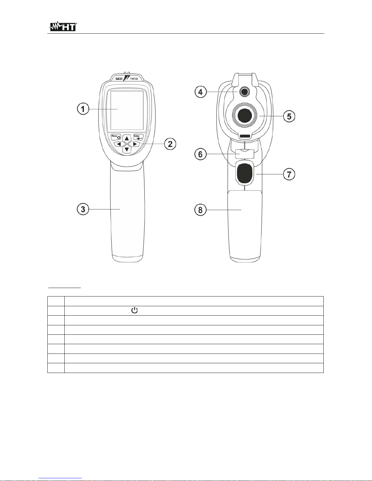
Fig. 1: Description of the instrument's front and backside
CAPTION:
1 LCD display
2
Function keys Menu/
, Enter, , , ,
3 Grip
4 In-built visual photo camera
5 IR sensor
6 USB port for connecting AC adapter/battery charger
7 Trigger key (T)
8 Battery compartment cover
Page 7
THT32
EN - 6
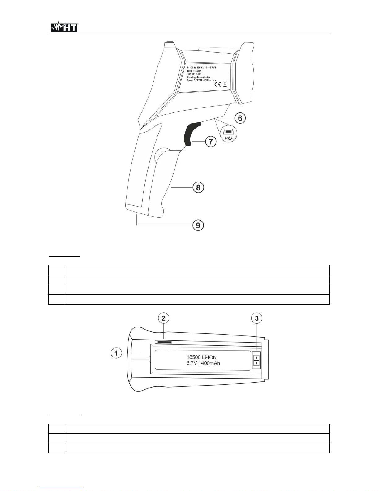
Fig. 2: Description of the instruments side
CAPTION
6 USB port for connecting AC adapter/battery charger
7 Trigger key (T)
8 Battery compartment cover
9 Hole for tripod insertion
Fig. 3: Description of the instrument's inputs and outputs
CAPTION
1 Inside of the battery compartment
2 Slot for micro SD card insertion
3 Battery insertion section
Page 8

THT32
EN - 7
4.2 DESCRIPTION OF FUNCTION KEYS
The instrument is provided with 6 function keys indicated as Menu/ , Enter, , , ,
and with a trigger key “T”.
4.2.1 Menu/ key
Press the Menu/ key to switch on the instrument. The instrument shows the normal
measuring screen. To switch off the instrument, press and hold for 2 seconds the Menu/
key. With the instrument switched on, press the Menu/ key to enter/exit the general
menu (see §)
4.2.2 Enter key
Pressing the Enter key allows entering the programming section an saving the value of
system parameters in the instrument’s general menu (see §).
4.2.3 Keys , , ,
The arrow keys ,,, allow setting system parameters in the instrument’s general
menu, and defining percentage and distance of the “Blending Fusion” function (see §). The
arrow keys ,,, also allow scrolling through the images saved in the micro SD card
(see §).
4.2.4 T key (Trigger)
Pressing the trigger key T found on the front part of the instrument allows activating the
Data HOLD function (freezing an image on the display) in order to save it in the micro SD
card (see §).
4.2.5 Inserting the micro SD Card
To insert the micro SD card, proceed as follows:
1. Open the battery compartment cover (see Fig. 1 – part 8)
2. Insert the micro SD card into the dedicated slot inside the battery compartment (see
Fig. 3 – part 2)
3. Note the “
” symbol at display
4. Restore the battery compartment cover to its position.
Page 9

THT32
EN - 8
5 OPERATING INSTRUCTIONS
5.1 DESCRIPTION OF THE MAIN INTERFACE
The instrument shows the following main interface on the display:
Fig. 4: Main instrument interface
The meaning of the symbols found on the display is described below.
Symbol Description
=0.95
Set value of object emissivity (see § 5.2.1)
13:55
Indication of the system's current time
Indication of fitted micro SD card
Indication of battery charge level
Indication of distance in “Blending Fusion” function (see § 5.1.1)
32.0°C
Indication of the temperature value associated with the central steady
cursor
Palette
Indication of colour palette (see § 5.2.4)
Cursor (red) associated with the Maximum temperature of the image on
the display.
Cursor (green) associated with the Minimum temperature of the image on
the display.
5.1.1 Adjusting the distance of the object in Blending Fusion function
The instrument is provided with the “Blending Fusion” function, which allows aligning the
infrared and the visual image. This function is therefore especially useful in the instant
search of heat maps found on the surface of the framed object. Due to the different
position of the lens and of the built-in photo camera, when the object is close to the lens,
the visual image tends to become bigger, while the IR image tends to reduce. When the
object is more than 2m far from the lens, this effect tends to disappear. The instrument
allows setting the distance of the object in order to compensate the effect at distances
shorter than 2m. Proceed as follows:
1. Frame the object to be measured
2. Use the arrow keys or to adjust the infrared/visual image mixing percentage from
0% to 100% in steps of 25%.
3. Use the arrow keys or to set the value of distance between lens and object. The
following values are available: 0.5m (1.6ft), 1m (3.3ft), 2m(6.6ft) and 3m(9.8ft)
Page 10

THT32
EN - 9
5.2 GENERAL MENU DESCRIPTION
By pressing the Menu/ key, the instrument shows the following general menu, which
allows accessing the internal functions:
Fig. 5: Instrument general menu
5.2.1 Menu EMS
In this section, it is possible to set the values of parameter Emissivity of the material of
the object to be measured. In order to carry out accurate temperature measurements, it is
important to define the correct emissivity value (), which represents the ability of a body to
emit infrared radiation, according to the kind of material the measured object is made of.
Table 1 shows the emissivity values for the most common materials. Emissivity takes
values between 0 (mirror or perfectly reflecting surface) and 1 (perfectly radiating black
body). Most of the painted or oxydized surfaces have an emissivity value of approximately
0.95.
Material Emissivity
Water 0.96
Stainless steel 0.14
Aluminium foil 0.09
Asphalt 0.96
Cement 0.97
Cast iron 0.81
Rubber 0.95
Wood 0.85
Bricks 0.75
Tape 0.96
Brass foil 0.06
Human skin 0.98
PVC plastic 0.93
Polycarbonate 0.80
Oxydized Copper 0.78
Rust 0.80
Paint 0.90
Earth 0.93
Table 1: Emissivity values of typical materials
Page 11

THT32
EN - 10
1. Select the item “EMS” with keys or and press the Enter key. The screen in Fig. 6
– Right side appears on the display.
Fig. 6: Emissivity adjustment
2. Use the keys or to set the desired emissivity value between 0.01 an 1.00
3. Press the “Enter” key to confirm an the Menu/ key to go back to the instrument’s
main screen.
5.2.2 Menu UNIT
In this section it is possible to define the temperature measuring unit used by the
instrument.
1. Select the item “UNIT” with keys or and press the Enter key. The screen in Fig. 7
appears on the display.
Fig. 7: Setting the temperature measuring unit
2. Use the or keys to set the measuring unit between options “°C” and “°F”.
3. Press the “Enter” key to confirm an the Menu/ key to go back to the instrument’s
main screen.
Page 12

THT32
EN - 11
5.2.3 Menu MAXMIN
In this section it is possible to enable/disable the display of cursors “MAX” and “MIN”
corresponding to the hottest (coloured in red) an coldest (coloured in green) spots of the
image on the display.
1. Select the item “MAXMIN” with keys or and press the Enter key. The screen in
Fig. 8 appears on the display.
Fig. 8: Setting of MAX and MIN display
2. Press the Enter key to enable (“”) or disable “x” the display of MAX and MIN values
on the display.
3. Press the Menu/ key to confirm, go back to the general menu and to the instrument’s
main screen.
5.2.4 Menu PLT
In this section it is possible to select the colour palette which can be associated to the IR
image.
1. Select the item “TAV” with keys or and press the Enter key. The screen in Fig. 9
appears on the display.
Fig. 9: Setting the colour palette
2. Use the or keys to set the colour palette among the following options: Grey1,
Grey2, Ironbow, Rainbow, HiCont (high contrast), Metal
3. Press the “Enter” key to confirm an the Menu/ key to go back to the instrument’s
main screen.
Page 13

THT32
EN - 12
5.2.5 Menu DATE
In this section it is possible to set the system’s date/time on the instrument.
1. Select the item “DATE” with keys or and press the Enter key. The screen in Fig.
10 appears on the display.
Fig. 10: System date/time setting – Initial selection
2. Use the or keys to select the options “Date” or “Time” and press the Enter key to
confirm. The following screen appears on the instrument's display:
Fig. 11: System date/time setting
– Configuration
3. Press the Enter key to move within the date and time fields.
4. Use the or keys to set the date with format “YYYY-MM-DD” and time with format
24H “HH-MM”.
5. Press the Menu/ key to confirm, go back to the general menu and to the instrument’s
main screen.
Page 14

THT32
EN - 13
5.2.6 Menu MEMORY
In this section it is possible to recall on the display and delete the images saved on the
micro SD card inserted in the instrument.
1. Select the item “MEMORY” with keys or and press the Enter key. The screen in
Fig. 12 appears on the display.
Fig. 12: Display of images saved in the memory
2. The screen in Fig. 12 – Middle appears in case the micro SD card is empty (no image
saved) or if no micro SD card has been inserted.
3. The screen in Fig. 12 – Right side appears when a saved image is recalled on the
display. The number at the top of the display indicates the memory location of the
saved image.
4. Use the or keys to scroll the images saved in the micro SD card.
5. Press the Enter key on the image recalled on the display. The symbol of the bin is
shown at the bottom of the display (see Fig. 12 – Right side).
6. Press the Enter key to confirm deletion of the image.
7. Press the Menu/
key to go back to the general menu and to the instrument’s main
screen.
5.2.7 Menu BGT
In this section, it is possible to set the value of reflected temperature on the instrument.
Objects with a low emissivity may reflect infrared energy coming from adjacent objects;
this energy is added to the energy of the object itself, thus causing possible measurement
mistakes. In several situations, there are sources of heat with a higher temperature than
the temperature found near the object being measured. In this case, it is necessary to
compensate this reflected energy by entering the presumed temperature value of the
adjacent heat source into the thermal camera. In most of the applications, the reflected
temperature is identical to the environmental temperature and has negligible effects on
temperature measurement on objects with a high emissivity.
1. Select the item
“BGT” with keys or and press the Enter key. The screen in Fig. 13
appears on the display.
Page 15

THT32
EN - 14
Fig. 13: Reflected temperature setting
2. Use the or keys to set the desired reflected temperature value.
3. Press the “Enter” key to confirm an the Menu/ key to go back to the instrument’s
main screen.
5.2.8 Menu ALARM
In this section, it is possible to set the high or low threshold values associated with the
acoustic alarm conditions on temperature measurements.
1. Select the item “ALARM” with keys or and press the Enter key. The screen
appears on the display.
Fig. 14: Setting of alarm thresholds on measurements
2. Use the or keys to select the options
“High” or “Low” and press the Enter key to
confirm. The screen in Fig. 14 – Middle appears on the display.
3. Use the or keys to set the values of “High” or “Low” alarm thresholds in a range -
20°C 300°C and the Enter key to enable the function. In these conditions, the
instrument’s alarm sounds when measured temperature is higher than the “High”
threshold or lower than the “Low” threshold.
4. Press the Menu/
key to go back to the general menu and to the instrument’s main
screen.
Page 16

THT32
EN - 15
5.2.9 Menu DISPLAY
In this section, it is possible to adjust the brightness of the display.
1. Select the item “DISPLAY” with keys or and press the Enter key. The screen
appears on the display.
Fig. 15: Setting display brightness
2. Use the or keys to reduce or increase the brightness of the display.
3. Press the Menu/ key to confirm, go back to the general menu and to the instrument’s
main screen.
5.2.10 Menu DIST
In this section, it is possible to set the measurement unit of distance associated with the
“Blending Fusion” function (see § 5.1.1).
1. Select the item “DIST” with keys or and press the Enter key. The screen appears
on the display.
Fig. 16: Setting the distance for “Blending Fusion” function
2. Use the or keys to set the measuring unit between options “m” and “ft”
3. Press the
“Enter” key to confirm an the Menu/ key to go back to the instrument’s
main screen
Page 17

THT32
EN - 16
5.2.11 Menu LANG
In this section it is possible to set the system language.
1. Select the item “LANG” with keys or and press the Enter key. The screen appears
on the display.
Fig. 17: System language setting
2. Use the or keys to select the system language among the available options.
3. Press the “Enter” key to confirm and the Menu/ key to go back to the instrument’s
main screen
5.2.12 Menu INFO
In this section it is possible to read the general information of the instrument and the
residual memory space of the fitted micro SD card.
1. Select the item “INFO” with keys or and press the Enter key. The screen appears
on the display.
Fig. 18: Visualization of instrument’s information
2. The followed information are shown at display:
Instrument model
Instrument serial number
Date of last calibration
Internal firmware version
Residual memory space of the micro SD card fitted inside instrument
3. Press the Menu/ key to go back to the instrument’s main screen.
Page 18

THT32
EN - 17
5.3 USING THE INSTRUMENT
1. Switch on the instrument by pressing the Menu/ key. The instrument shows the initial
screen for a few seconds, then it shows the instrument’s main screen.
2. The typical application of thermal cameras is the one in which it is necessary to detect
a temperature difference between two adjacent objects, as this kind of analysis is often
sufficient to identify heat maps, anomalies in electrical and mechanical appliances, etc.
In these situations, in which it is not strictly necessary to obtain an accurate
temperature measurement, you can set emissivity value to “1” (see § 5.2.1).
3. Enable detection of MAX and MIN temperature values of the image (see § 5.2.3), the
distance/percentage level of the “Blending Fusion” function (see § 5.1.1) and the
desired colour palette (see § 5.2.4).
4. Frame the objects to be measured. The instrument displays the temperature values
associated with the measuring cursors.
5. Use the trigger key T to freeze the image. The following screen appears on the display:
Fig. 19: Image saving
6. Press the Enter key to save the image on the micro SD card. The instrument saves the
images in a sequence with file name ”IMGxxxxx.BMP”. Otherwise, press the Menu/
key to unfreeze the image without saving it.
7. Enter the
“MEMORY” menu (see § 5.2.6) to see the saved images again.
5.4 TRANSFERRING THE IMAGES ONTO THE PC
The instrument allows saving the images on an external micro SD card and transferring
them onto the PC by using the USB cable. Both the micro SD card and the cable are
provided with the instrument. Proceed as follows:
1. Insert the micro SD card into the dedicated slot inside the battery compartment (see
Fig. 3
– Part 2).
2. Connect the USB cable to the instrument (see Fig. 2 – Part 6) and to the PC.
4. In “My Computer”, search for the removable disk associated with the micro SD card
and copy the files ”IMGxxxxx.BMP” of the desired images to a PC folder.
Page 19

THT32
EN - 18
6 MAINTENANCE
6.1 GENERAL INFORMATION
1. The instrument you purchased is a precision instrument. While using and storing the
instrument, carefully observe the recommendations listed in this manual in order to
prevent possible damage or danger during use.
2. Do not use the instrument in environments with high humidity levels or high
temperatures. Do not expose to direct sunlight.
3. Always switch off the instrument after use. In case the instrument is not to be used for a
long time, remove the battery to avoid liquid leaks that could damage the instrument’s
internal circuits.
6.2 RECHARGING THE INTERNAL BATTERY
The instrument is designed to be supplied with a Li-ION rechargeable battery. With symbol
“ ” shown on the display, it is necessary to recharge the battery.
CAUTION
The battery must not be removed from the instrument while recharging.
Recharge the battery at environmental temperature and, anyway, in a
range between 0°C and 50°C (32°F and 122°F).
When using the instrument for the first time, recharge the battery for at
least 6 hours.
1. Connect the battery charger provided with the instrument to the AC electric mains and
the mini USB port to the instrument's input (see Fig. 2 – Part 6). The symbol “ ”
appears on the display
2. The charging process takes approximately 3 hours. When operation is complete,
disconnect the battery charger from the instrument and from the electric mains, when
the display shows the symbol “ ” of full battery charge.
6.3 CLEANING THE INSTRUMENT
Use a soft and dry cloth to clean the instrument. Never use wet cloths, solvents, water, etc.
6.4 END OF LIFE
WARNING: this symbol found on the instrument indicates that the appliance, its
accessories and the batteries must be collected separately and correctly
disposed of.
6.5 ACCESSORIES
6.5.1 Accessories provided
Rechargeable Li-ION battery
Adapter AC/DC 100-240V/5V
Micro SD card, 4GB + SD card reader
USB cable
Tripod
ISO9000 calibration certificate
User manual
Transport case
Page 20

THT32
EN - 19
7 TECHNICAL SPECIFICATIONS
Range Sensitivity Accuracy Resolution Image frequency
-20°C300°C
<0.15°C
[2%rdg + 2°C]
32x31pxl 9Hz
General specifications
Type of IR sensor UPC (Uncooled Pyroelectric Ceramic)
Spectrum response: 6.5 14m
Visual range (FOV) / Lens: 39° x 38° / 10mm
Focusing: automatic
Minimum focus distance: 0.5m
Temperature readings: °C, °F
Available colour palettes: 6
Emissivity correction: 0.01 ÷ 1.00 in steps of 0.01
Measuring functions: corrections according to emissivity and reflected
temperature
Measuring cursors: 3 (Fixed, Max Temp., Min Temp.)
Inbuilt photo camera: 48608pxl
Blending Fusion function: mixing 0% 100% in steps of 25%
Alarms on measurements: MAX and MIN thresholds
Memory: micro SD card 4GB (>6000 BMP images)
Max allowed micro SD card: 16GB
PC interface: USB 2.0
Power supply
Internal supply: rechargeable Li-ION battery, 3.7V 1400mAh
External supply: adapter 100-240VAC (50/60Hz)/5VDC
Battery duration: 2 hours (stand-by)
Auto Power OFF: after 10 minutes' idling
Display
Characteristics: colour, LCD, TFT 2.2
”, 320x240pxl, high contrast
Mechanical characteristics
Size (L x W x H): 205 x 155 x 62mm (8 x 6 x 2in)
Weight (battery included): 410g (14 ounces)
7.1 ENVIRONMENT
7.1.1 Environmental conditions for use
Operating temperature: 0°C ÷ 50°C (32°F ÷ 122°F)
Storage temperature: -20°C ÷ 60°C (-4°F ÷ 140°F)
Allowable relative humidity: 10 ÷ 90%RH
This instrument complies with Directive EMC 2004/108/EC
This instrument satisfies the requirements of European Directive 2011/65/EU (RoHS) and
2012/19/EU (WEEE)
Page 21

THT32
EN - 20
8 ASSISTANCE
8.1 WARRANTY CONDITIONS
This instrument is warranted against any material or manufacturing defect, in compliance
with the general sales conditions. During the warranty period, defective parts may be
replaced. However, the manufacturer reserves the right to repair or replace the product.
Should the instrument be returned to the After-sales Service or to a Dealer, transport will
be at the Customer's charge. However, shipment will be agreed in advance. A report will
always be enclosed to a shipment, stating the reasons for the product's return. Only use
original packaging for shipment; any damage due to the use of non-original packaging
material will be charged to the Customer. The manufacturer declines any responsibility for
injury to people or damage to property.
The warranty shall not apply in the following cases:
Repair and/or replacement of accessories and battery (not covered by warranty).
Repairs that may become necessary as a consequence of an incorrect use of the
instrument or due to its use together with non-compatible appliances.
Repairs that may become necessary as a consequence of improper packaging.
Repairs which may become necessary as a consequence of interventions performed
by unauthorized personnel.
Modifications to the instrument performed without the manufacturer's explicit
authorization.
Use not provided for in the instrument's specifications or in the instruction manual.
The content of this manual cannot be reproduced in any form without the manufacturer's
authorization.
Our products are patented and our trademarks are registered. The manufacturer
reserves the right to make changes in the specifications and prices if this is due to
improvements in technology.
8.2 ASSISTANCE
If the instrument does not operate properly, before contacting the After-sales Service,
please check the conditions of the batteries and replace them, if necessary. Should the
instrument still operate improperly, check that the product is operated according to the
instructions given in this manual. Should the instrument be returned to the After-sales
Service or to a Dealer, transport will be at the Customer's charge. However, shipment will
be agreed in advance. A report will always be enclosed to a shipment, stating the reasons
for the product's return. Only use original packaging for shipment. Any damage due to the
use of non-original packaging material will be charged to the Customer.
 Loading...