

Page 1

Copyright HT ITALIA 2017 Release EN 2.00 - 20/06/2017
ENGLISH
User manual
Page 2

QUICKLAN 6050N
EN - 1
Table of contents:
1. PRECAUTIONS AND SAFETY MEASURES ............................................................... 2
1.1. Preliminary instructions ........................................................................................................ 2
1.2. During use ............................................................................................................................ 2
1.3. After use ............................................................................................................................... 2
2. GENERAL DESCRIPTION ........................................................................................... 3
3. PREPARATION FOR USE ........................................................................................... 3
3.1. Initial checks ........................................................................................................................ 3
3.2. Instrument power supply ...................................................................................................... 3
3.3. Storage ................................................................................................................................ 3
4. NOMENCLATURE ........................................................................................................ 4
4.1. Description of the instrument ............................................................................................... 4
4.2. Description of the symbols shown on the display ................................................................ 4
4.3. Description of function keys ................................................................................................. 5
4.3.1. ON/OFF key ................................................................................................................................. 5
4.3.2. Arrow keys ................................................................................................................................... 5
4.3.3. L/W key ........................................................................................................................................ 5
4.3.4. SET/UNIT key .............................................................................................................................. 5
4.3.5. TEST/ .................................................................................................................................... 5
5. OPERATING INSTRUCTIONS ..................................................................................... 6
5.1. Instrument settings ............................................................................................................... 6
5.1.1. Auto Power OFF function ............................................................................................................ 6
5.1.2. Display backlight .......................................................................................................................... 6
5.1.3. Setting the cable type .................................................................................................................. 7
5.1.4. Setting cable length measuring unit ............................................................................................ 7
5.2. Test of cable mapping with RJ45 connector ........................................................................ 8
5.2.1. Mapping test results .................................................................................................................... 9
5.2.2. Description of errors of split pairs .............................................................................................. 11
5.2.3. Test with more remote units ...................................................................................................... 11
5.3. Test of cable mapping with RJ11 connector ...................................................................... 12
5.4. Test of Coax cable mapping with F connector ................................................................... 13
5.5. Measurement of cable length ............................................................................................. 14
5.5.1. Calibration of cable length ......................................................................................................... 14
6. MAINTENANCE ......................................................................................................... 16
6.1. General information............................................................................................................ 16
6.2. Battery replacement ........................................................................................................... 16
6.3. Cleaning the instrument ..................................................................................................... 16
6.4. End of life ........................................................................................................................... 16
7. TECHNICAL SPECIFICATIONS ................................................................................ 17
7.1. Technical characteristics .................................................................................................... 17
7.2. General characteristics ...................................................................................................... 17
7.3. Environment ....................................................................................................................... 17
7.3.1. Environmental conditions for use .............................................................................................. 17
7.4. Accessories ........................................................................................................................ 17
7.4.1. Accessories provided ................................................................................................................ 17
7.4.2. Optional accessories ................................................................................................................. 17
8. SERVICE .................................................................................................................... 18
8.1. Warranty conditions ........................................................................................................... 18
8.2. After-sales Service ............................................................................................................. 18
Page 3
QUICKLAN 6050N
EN - 2
1. PRECAUTIONS AND SAFETY MEASURES
The instrument has been designed in compliance with the safety directives relevant to
electronic measuring instruments. For your safety and in order to prevent damaging the
instrument, please carefully follow the procedures described in this manual and read all
notes preceded by symbol with the utmost attention. Before and after carrying out
measurements, carefully observe the following instructions:
Do not carry out any measurement in humid environments.
Do not carry out any measurements in case gas, explosive materials or flammables are
present, or in dusty environments.
Avoid any contact with the circuit being measured if no measurements are being
carried out.
Avoid any contact with exposed metal parts, with unused measuring probes, circuits,
etc.
Do not carry out any measurement in case you find anomalies in the instrument such
as deformation, breaks, substance leaks, absence of display on the screen, etc.
1.1. PRELIMINARY INSTRUCTIONS
Before using the instrument, please carefully read this user manual.
Each instruction preceded by symbol must be carefully complied with in order to
prevent accidents or damage.
Make sure the batteries are installed correctly.
This instrument must be used only by skilled personnel capable of taking the
appropriate safety precautions.
Do not carry out any measurement under conditions outside the ranges specified in this
manual.
CAUTION
Only connect the instrument to disconnected (non-live) cables. Connection to
active telephone lines and/or data nets may damage the instrument.
1.2. DURING USE
Carefully read the following recommendations and precautions for use:
CAUTION
Should the instrument display symbol “ ” it is necessary to stop measuring
and replace the batteries. Never replace batteries while the instrument is
installed on the conductor.
Do not use the instrument, if damaged.
Do not use the instrument outdoors.
Do not perform any test under environmental conditions exceeding the limits indicated
in § 7.3.1.
Do not expose the instrument to water.
1.3. AFTER USE
Always switch off the instrument after use.
In case the instrument is not to be used for a long time, remove the batteries.
Page 4

QUICKLAN 6050N
EN - 3
2. GENERAL DESCRIPTION
Model QUICKLAN6050N allows carrying out tests on LAN network cable wirings,
telephone cables and coaxial cables. The instrument has the following features:
Test of wiring errors on LAN network cables with RJ45 connector in CAT5 and CAT6.
Test of wiring errors on telephone network cables with RJ11 connector.
Test of wiring errors on COAX cables with F connector.
Detection of wiring errors on UTP (unshielded) and STP (shielded) cables.
Detection of up to 4 RJ45 remote units for multiple tests.
Measurement of cable length
Display with backlight
Auto power off
3. PREPARATION FOR USE
3.1. INITIAL CHECKS
Before shipping, the instrument has been checked from an electric as well as mechanical
point of view. All possible precautions have been taken so that the instrument is delivered
undamaged.
However, we recommend generally checking the instrument in order to detect possible
damage suffered during transport. In case anomalies are found, immediately contact the
forwarding agent.
We also recommend checking that the packaging contains all components indicated in §
7.4.1. In case of discrepancy, please contact the Dealer.
In case the instrument should be returned, please follow the instructions given in § 8.
3.2. INSTRUMENT POWER SUPPLY
The instrument is supplied with 6x1.5V alkaline batteries type AAA IEC LR03, included in
the package. Should the instrument display the flat battery symbol
“ ”, stop measuring
and replace the batteries (see § 6.2). Never replace batteries while the instrument is
connected to the system.
3.3. STORAGE
In order to guarantee precise measurement, after a long storage time under extreme
environmental conditions, wait for the instrument to come back to normal operating
conditions (see § 7.3).
Page 5
QUICKLAN 6050N
EN - 4
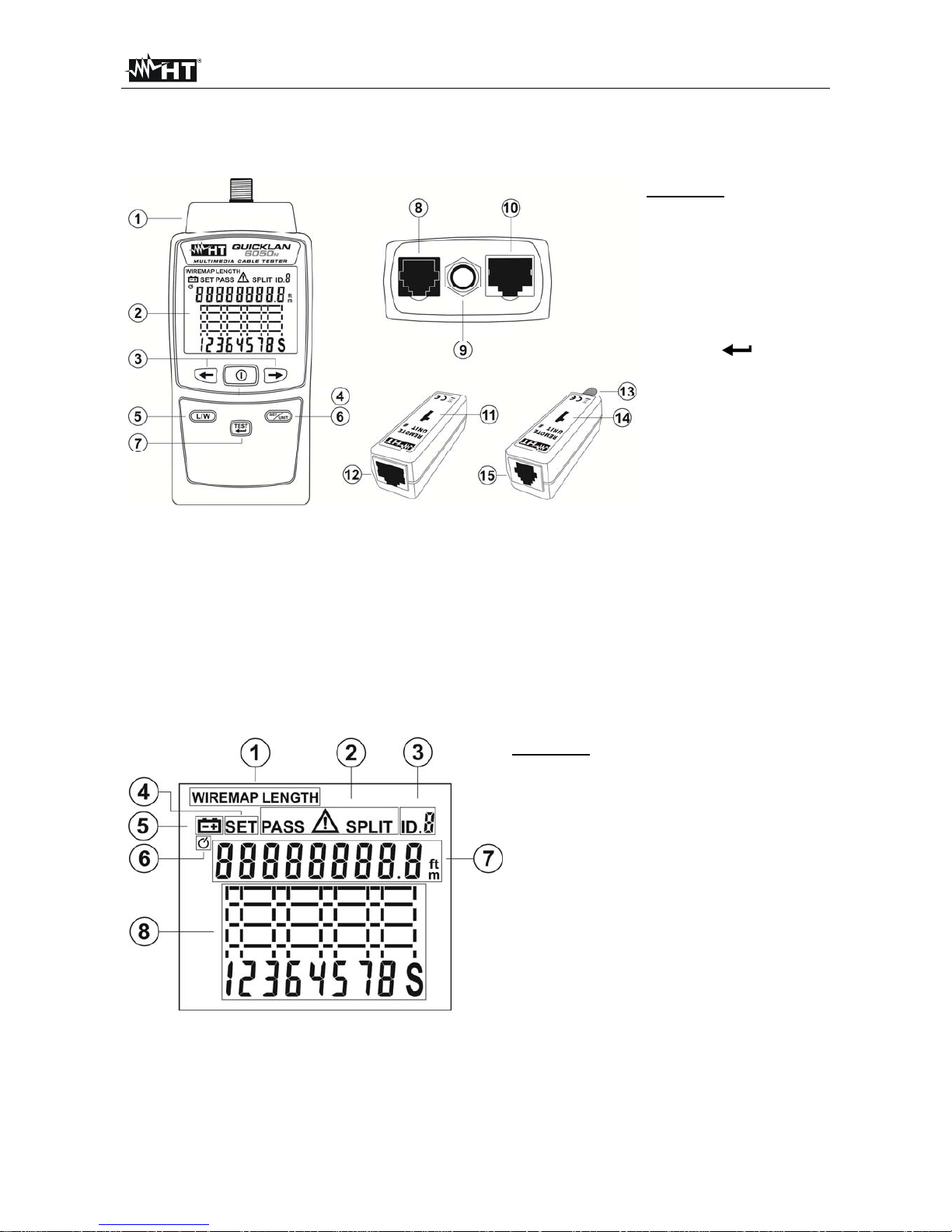
4. NOMENCLATURE
4.1. DESCRIPTION OF THE INSTRUMENT
CAPTION:
1. Section of input
connectors
2. LCD display
3. Arrow keys
4. ON/OFF key
5. L/W key
6. SET/UNIT key
7. TEST/ key
8. RJ11 connector
9. F connector
10. RJ45 connector
11. Remote unit #1 for
RJ45 cables
12. RJ45 connector for
remote unit
13. F connector for
remote unit
14. Remote unit #1 for
RJ11 and COAX
cables
15. RJ11 connector for
remote unit
Fig. 1: Description of the instrument
4.2. DESCRIPTION OF THE SYMBOLS SHOWN ON THE DISPLAY
CAPTION:
1. Test symbols Mapping/Length
2. Test symbols Passed, Error, Split
3. Identifier ID remote unit
4. SET symbol
5. Low battery symbol
6. Auto Power Off (APO) symbol
7. Display with indication of
measured Length and status of
cable pairs
8. Graphic LCD to display error
conditions
Fig. 2: Description of the symbols shown on the display
Page 6

QUICKLAN 6050N
EN - 5
4.3. DESCRIPTION OF FUNCTION KEYS
4.3.1. ON/OFF key
Press the key to switch on or off the instrument. The LCD display shows all of its
segments for a moment. The key is also used to set the instrument’s parameters (see §
5.1).
4.3.2. Arrow keys
The arrow keys , are used to set the instrument’s parameters (see § 5.1) and to
select the cable pairs for measuring length (see § 5.5).
4.3.3. L/W key
Use the L/W key to:
Go to the Mapping test screen (WIREMAP) and to the Length measuring screen
(LENGTH).
Set the length measuring unit (see § 5.1.4).
Define calibration operations of cable length (see § 5.5.1).
4.3.4. SET/UNIT key
Press the SET/UNIT key to select the current remote unit in case the test is performed with
more remote units present (see § 5.2.3). Press and hold the SET/UNIT key for 3s in order
to enter/exit the section for setting the internal parameters of the instrument and navigate
inside it (see § 5.1).
4.3.5. TEST/
Press the TEST/ key to activate a measuring test and to confirm the values of
parameters when programming the instrument (see § 5.1).
Page 7

QUICKLAN 6050N
EN - 6
5. OPERATING INSTRUCTIONS
5.1. INSTRUMENT SETTINGS
5.1.1. Auto Power OFF function
1. Switch on the instrument by pressing the key.
2. Press and hold the SET/UNIT key for 3s. The screen in Fig. 3 – left side appears on the
display.
Fig. 3: Auto Power Off setting (APO)
3. Press the SET/UNIT key to activate the Auto Power Off function of the instrument. The
message “oFF” appears on the display.
4. Press the arrow keys or to activate the function. The message “On” flashes
and symbol “ ” appears on the display (see Fig. 3 – right side).
5. Press the TEST/ key to save setting and go back to main screen.
5.1.2. Display backlight
1. Switch on the instrument by pressing the key.
2. Press and hold the SET/UNIT key for 3s. The screen in Fig. 3 – left side appears on
the display.
3. Press the arrow keys or to go to the display’s backlight setting. The screen in
Fig. 4
– left side appears on the display.
Fig. 4: Setting display backlight
4. Press the SET/UNIT key. The message “oFF” appears on the display.
5. Press the arrow keys
or to activate the function. Message “On” flashes.
6. Press the TEST/
key to save setting and go back to main screen.
Page 8

QUICKLAN 6050N
EN - 7
5.1.3. Setting the cable type
1. Switch on the instrument by pressing the key.
2. Press and hold the SET/UNIT key for 3s. The screen in Fig. 3 – left side appears on
the display.
3. Press the arrow keys or until you display the screen in Fig. 5 - left side
Fig. 5: Setting the cable type
4. Press the SET/UNIT key. Parameter “0” flashes on the display. This parameter allows
selecting one of the 10 numeric configurations saved by the user according to the type
and possible calibration of cable length (see § 5.5.1).
5. Press the arrow key or to select the value among the options 0 ÷ 9.
6. Press the SET/UNIT key to go to the selection of cable type. Parameter “CA5” flashes
on the display.
7. Press the arrow key or to select the cable type among the options: CA5
(CAT5), CA6 (CAT6), AJII (RJ11), COA (COAX)
8. Press the SET/UNIT key to go to the selection of cable type with RJ45 connector.
Parameter “StP” flashes on the display.
9. Press the arrow keys or to select the possible options. StP (shielded STP
cable) or UtP (unshielded UTP cable)
10. Press the TEST/ key to save all settings and go back to main screen.
5.1.4. Setting cable length measuring unit
1. Press and hold the L/W key and switch on the instrument by pressing the
key. The
instrument shows the screen in Fig. 6
– left side.
Fig. 6: Setting length measuring unit
2. Press the arrow keys or to select measuring unit “Mt” (meter) or “Ft” (foot)
flashing on the display.
3. Press the TEST/ key to save setting and go back to main screen.
Page 9

QUICKLAN 6050N
EN - 8
5.2. TEST OF CABLE MAPPING WITH RJ45 CONNECTOR
The test allows checking the cable mapping of LAN networks, in CAT5 or CAT6, of type
UTP or STP with RJ45 connector, detecting possible wiring errors. Proceed as follows:
1. Switch on the instrument by pressing the key.
2. Select the category (CAT5 or CAT6) of the cable to be tested (see § 5.1.3).
3. Select the type (UTP, STP) of the cable to be tested (see § 5.1.3).
4. Connect the ends of the cable to be tested to the instrument’s input RJ45 connector
(see Fig. 1 – part 10) and to the remote unit #1 or, if necessary, use the patch cables
provided as shown in Fig. 7.
Fig. 7: Instrument connection through patch cables
5. Press the TEST/
key. The instrument carries out the test according to the type of
cable set, displaying the message
“PASS” for a correct test or symbol “ ” together
with flashing pairs in case of wiring error (see § 5.2.1).
6. Press the L/W key to display cable length (see § 5.5).
CAUTION
Connection of the remote unit is necessary in order to correctly
perform the test.
Only connect the instrument to disconnected (non-live) cables.
Connection to active telephone lines or data nets may damage the
instrument.
Page 10

QUICKLAN 6050N
EN - 9
5.2.1. Mapping test results
Situation Description Display
Message
“PASS” on the display
Correctly performed test on
UTP cable connected to
remote unit #1
Message
“PASS” on the display
Correctly performed test on
STP cable connected to
remote unit #1
Symbol on the display
OPEN PAIR
Cables of the pair 4-5
interrupted
Symbol on the display
SHORT-CIRCUITED
CABLES
Cable 1 of the pair 1-2
short-circuited with
cable 8 of pair 7-8
Cable 3 of the pair 3-6
short-circuited with
cables 4 and 5 of pair 45
Cables of the pair 4-5
short-circuited
Page 11

QUICKLAN 6050N
EN - 10
Symbol on the display
INVERTED PAIR
Cables of pair 3-6 inverted
Symbol on the display
CROSSED PAIRS
Cables of pair 3-6 crossed
with cables of pair 4-5
Symbol on the display
GENERIC ERROR
(MISWIRE)
Cables of pair 1-2
inverted
Cable 4 of the pair 4-5
short-circuited with
cable 8 of pair 7-8
Screen S open
Symbol on the display
SPLIT PAIRS
Correspondence pin to pin
is maintained, but the
cables of pairs 3-6 and 4-5
are physically crossed
CAUTION
The instrument identifies the SPLIT error, making the concerned pairs flash
and showing symbol
“SPLIT” on the display.
The error condition SPLIT is detected by the instrument only in case no
other error condition is present and with a cable length of at least 5m (15ft).
Page 12

QUICKLAN 6050N
EN - 11
5.2.2. Description of errors of split pairs
Inside the network cables, the eight conductors are twisted two by two, thus forming four
pairs: 1-2, 3-6, 4-5, 7-8 and this guarantees the performance declared by the
manufacturer. The error condition SPLIT PAIRS is given by the exchange of two
conductors belonging to different pairs, found in both positions of the cable to be tested
(see Fig. 8). Correspondence pin to pin is maintained, but the cables of the two pairs are
physically crossed. The two pairs thus crossed influence each other, thus making data
exchange at high frequency/speed difficult, if not impossible.
Fig. 8: Description of error condition “Split Pairs”
5.2.3. Test with more remote units
The instrument allows carrying out mapping tests also on multiple cables by using other
optional remote units and is capable of recognizing up to 4 remote units.
1. Switch on the instrument by pressing the key.
2. Select the category (CAT5, CAT6) of the cables to be tested (see § 5.1.3).
3. Select the type (UTP, STP) of the cables with RJ45 connector to be tested (see §
5.1.3).
4. Connect the end of one of the cables to be tested (e.g.: #3) to the instrument’s input
connector RJ45 and to the corresponding remote unit (e.g.: #3) using the patch cables
as shown in Fig. 9.
Fig. 9: Connection of the instrument to more remote units
5. Press the SET/UNIT key to select the current remote unit (e.g.: #3)
6. Press the TEST/ key to perform the test on the relevant cable.
7. Disconnect the instrument, connect it to another cable and repeat the operations
starting from point 5.
Page 13

QUICKLAN 6050N
EN - 12
5.3. TEST OF CABLE MAPPING WITH RJ11 CONNECTOR
1. Switch on the instrument by pressing the key.
2. Select the type of cable AJII (RJ11) to be tested (see § 5.1.3).
3. Connect the ends of the cable to be tested to the instrument’s input RJ11 connector
(see Fig. 1 – part 8) and to the remote unit #1 (see Fig. 10). if necessary, use the patch
cables provided as shown in Fig. 7.
Fig. 10: Connection of the instrument to cable with RJ11 connector
4. Press the TEST/ key. The instrument carries out the test and displays the message
“PASS” for a correct test (see Fig. 11) or symbol “ ” together with flashing pairs in
case of wiring error (see § 5.2.1).
Fig. 11: Display of correct test on cable with RJ11 connector
5. Press the L/W key to display cable length (see § 5.5).
CAUTION
Connection of the remote unit is necessary in order to correctly
perform the test.
Only connect the instrument to disconnected (non-live) cables.
Connection to active telephone lines or data nets may damage the
instrument.
Page 14

QUICKLAN 6050N
EN - 13
5.4. TEST OF COAX CABLE MAPPING WITH F CONNECTOR
1. Switch on the instrument by pressing the key.
2. Select the type of cable COA (COAX) to be tested (see § 5.1.3).
3. Connect the ends of the cable to be tested to the instrument’s input COAX connector
(see Fig. 1 – part 9) and to the remote unit #1 (see Fig. 12)
Fig. 12: Connection of the instrument to COAX cable with F connector
4. Press the TEST/ key. The instrument carries out the test and displays the message
“PASS” for a correct test (see Fig. 13 – left side) or symbol “ ” together with flashing
pairs in case of interrupted cable (see § Fig. 13 – right side).
Fig. 13: Displaying the test on COAX cable with F connector
5. Press the L/W key to display cable length (see § 5.5).
CAUTION
Connection of the remote unit is necessary in order to correctly
perform the test.
Only connect the instrument to disconnected (non-live) cables.
Connection to active telephone lines or data nets may damage the
instrument.
Page 15

QUICKLAN 6050N
EN - 14
5.5. MEASUREMENT OF CABLE LENGTH
The instrument measures the length of cables with RJ45 connectors of type UTP/STP, on
RJ11 cables and on coaxial cables (COAX) with F connector. Proceed as follows:
1. Switch on the instrument by pressing the key.
2. Enter the programming menu (see § 5.1.3) and select the numeric marker (values
between 0 and 9) to which the type and possible calibration of cable length are
associated (see § 5.5.1).
3. Connect the end of the cable to be tested to input connector RJ45, RJ11 or COAX
4. Connect the other end of the cable to be tested to connector RJ45, RJ11 o r COAX of
remote unit #1
5. Press the L/W key to select the cable length measuring function
6. Press the TEST/
key to measure length with reference to pair “1-2” for RJ45 and
RJ11 cables (see Fig. 14
– left side) or for COAX cables (see Fig. 14 – right side).
Fig. 14: Cable length measuring results
7. Press the arrow keys or to display the length of the remaining pairs “3-6”, “4-5” and
“7-8” of the RJ45 cable being tested (pairs “3-6” and “4-5” for RJ11 cables).
5.5.1. Calibration of cable length
In order to obtain accurate measurements, it is possible to calibrate the instrument on the
specific cable being used. In order to perform calibration, connect the reference cable (with
an already known length) directly to the instrument without patch cables and follow this
procedure:
1. Switch on the instrument by pressing the key.
2. Press and hold the L/W key for 3s. The screen in Fig. 15 appears on the display.
Fig. 15: Calibration settings of cable length
Page 16

QUICKLAN 6050N
EN - 15
3. The numeric marker “0” (default) flashes on the display. Press the arrow key or
to select the value among the options 0 ÷ 9. This numeric marker is associated to
the one considered when setting the type of cable (see § 5.1.3).
4. Press the SET/UNIT key to set the length of the reference cable between: 10 ÷ 250
(unit m) or 30 ÷ 750 (unit ft). The value flashes on the display. Use the arrow keys
or in order to respectively decrease or increase the value (press and hold the keys
for a quick selection).
5. Press the SET/UNIT key to select the activation/deactivation of c able calibration. Use
the arrow keys or to select the options: yes (SI) or no (NO)
6. Press the TEST/
key to save all settings and go back to main screen.
7. Perform measurement as indicated in § 5.5. Values will be considered by the
instrument as a reference for that specific length measurement.
CAUTION
In case it is not necessary to calibrate the length of the cable, always select
option “no” in order to prevent possible incorrect measurements.
Page 17

QUICKLAN 6050N
EN - 16
6. MAINTENANCE
6.1. GENERAL INFORMATION
1. While using and storing the instrument, carefully observe the recommendations listed in
this manual in order to prevent possible damage or danger during use.
2. Do not use the instrument in environments with high humidity levels or high
temperatures. Do not expose to direct sunlight.
3. Always switch off the instrument after use. In case the instrument is not to be used for a
long time, remove the battery to avoid liquid leaks that could damage the instrument’s
internal circuits.
6.2. BATTERY REPLACEMENT
When the LCD display shows symbol “ ”, batteries must be replaced.
CAUTION
Only expert and trained technicians should perform this operation. Before
carrying out this operation, make sure you have disconnected all cables from
the input terminals.
Fig. 16: Replacing internal batteries
1. Switch off the instrument and remove the cable from the input terminal.
2. Lift the stand, press the tag of the battery compartment cover to open it (see Fig. 16).
3. Remove the batteries and replace them with new batteries of the same type (see §
7.2), respecting the indicated polarity.
4. Restore the battery compartment cover to its position.
5. Do not scatter old batteries into the environment. Use the relevant containers for
disposal.
6.3. CLEANING THE INSTRUMENT
Use a soft and dry cloth to clean the instrument. Never use wet cloths, solvents, water, etc.
6.4. END OF LIFE
WARNING: the symbol on the instrument indicates that the appliance and its
accessories must be collected separately and correctly disposed of.
Page 18

QUICKLAN 6050N
EN - 17
7. TECHNICAL SPECIFICATIONS
7.1. TECHNICAL CHARACTERISTICS
Input connectors RJ45, RJ11, COAX (F)
Cable type RJ45: UTP, STP
Category: CAT5, CAT6
Considered standard: TIA/EIA 568B
Detected wiring errors: open pairs, short-circuited pairs, inverted pairs,
crossed pairs
slit pairs, generic errors
Max operating altitude: 2000m (6562ft)
Length range (1): 10m ÷ 250m (30ft ÷ 750ft)
Resolution: 0.1m (ft)
Accuracy: (10%rdg + 1.0m) ; (10%rdg + 3.0ft)
(1) For Split pair test, a cable length of at least 5m (15ft) is necessary
7.2. GENERAL CHARACTERISTICS
Mechanical characteristics
Size (L x W x H): 156 x 73 x 35mm (6 x 3 x 1in)
Weight (battery included): 170g (6ounces)
Remote unit size (L x W x H): 72 x 20 x 23mm (3 x 1 x 1in)
Remote unit weight: 25g (1ounce)
Power supply
Battery type: 6x1.5V batteries type AAA LR03
Battery life: 200 continuous tests
Auto Power OFF: after 15 minutes' idling
7.3. ENVIRONMENT
7.3.1. Environmental conditions for use
Reference temperature: 5°C ÷ 40 °C (41°F ÷ 104 °F)
Allowable relative humidity: <80%RH
Storage temperature: -10°C ÷ 60°C (14°F ÷ 140 °F)
Storage humidity: <70%RH
Pollution level: 2
This instrument complies with European Directive EMC 2014/30/EU
This instrument satisfies the requirements of European Directive 2011/65/EU (RoHS)
and 2012/19/EU (WEEE).
7.4. ACCESSORIES
7.4.1. Accessories provided
Remote unit RJ45 #1
Code. RT-01
Remote unit RJ11/COAX #1
Code. RJX-01
Patch cable RJ45/RJ45, CAT5, STP, 20cm, 2pcs
Patch cable RJ11, 20cm
Patch cable COAX (F), 25cm
Batteries (not inserted)
Carrying bag
User manual
7.4.2. Optional accessories
Set of 3 RJ45 remote units #2,#3,#4 + 3 patch cables
Code RT-0204
Page 19

QUICKLAN 6050N
EN - 18
8. SERVICE
8.1. WARRANTY CONDITIONS
This instrument is warranted for 1 year against any material or manufacturing defect, in
compliance with the general sales conditions. During the warranty period, defective parts
may be replaced. However, the manufacturer reserves the right to repair or replace the
product. Should the instrument be returned to the After-sales Service or to a Dealer,
transport will be at the Customer's charge. However, shipment will be agreed in advance.
Only use original packaging for shipment; any damage due to the use of non-original
packaging material will be charged to the Customer. The manufacturer declines any
responsibility for injury to people or damage to property. The warranty shall not apply in
the following cases:
Repairs that may become necessary as a consequence of an incorrect use of the
instrument or due to its use together with non-compatible appliances.
Repairs that may become necessary as a consequence of improper packaging.
Repairs which may become necessary as a consequence of interventions performed
by unauthorized personnel.
Modifications to the instrument performed without the manufacturer's explicit
authorization.
Use not provided for in the instrument's specifications or in the instruction manual.
The content of this manual cannot be reproduced in any form without the manufacturer's
authorization.
Our products are patented and our trademarks are registered. The manufacturer
reserves the right to make changes in the specifications and prices if this is due to
improvements in technology.
8.2. AFTER-SALES SERVICE
If the instrument does not operate properly, before contacting the After-sales Service,
please check the conditions of battery and cables and replace them, if necessary. Should
the instrument still operate improperly, check that the product is operated according to the
instructions given in this manual. Should the instrument be returned to the After-sales
Service or to a Dealer, transport will be at the Customer's charge. However, shipment will
be agreed in advance. A report will always be enclosed to a shipment, stating the reasons
for the product's return. Only use original packaging for shipment; any damage due to the
use of non-original packaging material will be charged to the Customer.
 Loading...