

Page 1
Copyright HT ITALIA 2012 Release EN 1.07 - 05/06/2012
400 Series
User manual
ISO410 - SPEED418 - COMBI419 - COMBI420
Page 2

400 Series
EN - 1
Table of contents:
1. SAFETY PRECAUTIONS AND PROCEDURES .......................................................... 4
1.1. Preliminary instructions ..................................................................................................... 4
1.2. During use ......................................................................................................................... 4
1.3. After use ............................................................................................................................ 5
1.4. Overvoltage categories - definitions .................................................................................. 5
2. GENERAL DESCRIPTION ........................................................................................... 6
2.1. Introduction ........................................................................................................................ 6
2.2. Instrument operation ......................................................................................................... 6
3. PREPARATION FOR USE ........................................................................................... 7
3.1. Initial checks ...................................................................................................................... 7
3.2. Instrument power supply ................................................................................................... 7
3.3. Calibration ......................................................................................................................... 7
3.4. Storage .............................................................................................................................. 7
4. OPERATION DESCRIPTION ....................................................................................... 8
4.1. Instrument description ....................................................................................................... 8
4.2. Backlighting ....................................................................................................................... 8
4.3. Keyboard description ......................................................................................................... 9
4.4. Display description ............................................................................................................ 9
4.5. Initial screen ...................................................................................................................... 9
5. MAIN MENU ............................................................................................................... 10
5.1. AUTO ÷ PWR .................................................................................................................. 10
5.2. SET – Instrument settings ............................................................................................... 10
5.2.1. Language ............................................................................................................................... 10
5.2.2. Auto power off ........................................................................................................................ 11
5.2.3. Nominal voltage ..................................................................................................................... 11
5.2.4. Frequency .............................................................................................................................. 11
5.2.5. System ................................................................................................................................... 11
5.3. MEM ................................................................................................................................ 11
6. ELECTRICAL SYSTEM TEST .................................................................................... 12
6.1. AUTO .............................................................................................................................. 12
6.1.1. Description of anomalous results ........................................................................................... 14
6.2. LOWOHM: Continuity test of earth leads with 200mA .................................................... 16
6.2.1. CAL mode .............................................................................................................................. 18
6.2.2. Description of anomalous results ........................................................................................... 19
6.3. M: Measurement of the insulation resistance ............................................................... 21
6.3.1. Description of anomalous results ........................................................................................... 23
6.4. RCD: Test on A-type and AC-type RCDs ........................................................................ 25
6.4.1. AUTO mode ........................................................................................................................... 27
6.4.2. x½ mode ................................................................................................................................ 28
6.4.3. x1, x2, x5 mode ...................................................................................................................... 29
6.4.4. mode ................................................................................................................................. 29
6.4.5. RA mode ................................................................................................................................ 30
6.4.6. Description of anomalous results ........................................................................................... 31
6.5. LOOP: Measurement of Line/Loop impedance ............................................................... 35
6.5.1. P-N mode ............................................................................................................................... 37
6.5.2. P-P mode ............................................................................................................................... 38
6.5.3. P-PE mode in TT or TN systems ........................................................................................... 39
6.5.4. P-PE mode in IT systems ...................................................................................................... 40
6.5.5. Description of anomalous results ........................................................................................... 40
6.6. R
A
15mA: measurement of the total earth resistance through the socket-outlet ............. 43
6.6.1. Description of anomalous results ........................................................................................... 45
6.7. 123: Phase sequence test ............................................................................................... 48
6.7.1. Description of anomalous results ........................................................................................... 51
7. AUXILIARY MEASUREMENTS .................................................................................. 52
7.1. AUX: real time measurement of the environmental parameters ..................................... 52
7.1.1. dB mode ................................................................................................................................. 53
Page 3

400 Series
EN - 2
7.1.2. AIR, RH, TMP °F, TMP °C, Lux mode ................................................................................... 54
7.1.3. Description of anomalous results ........................................................................................... 54
7.2. LEAK: real time measurement of the leakage current through an external clamp .......... 55
7.2.1. Description of anomalous results ........................................................................................... 56
8. MAINS ANALYSIS ...................................................................................................... 57
8.1. PWR: real time measurement of the mains parameters ................................................. 57
8.1.1. PAR mode .............................................................................................................................. 58
8.1.2. HRM V ane HRM I mode ....................................................................................................... 58
9. MEMORY ................................................................................................................... 59
9.1. How to save a measure ................................................................................................... 59
9.1.1. Description of anomalous results ........................................................................................... 59
9.2. Saved data management ................................................................................................ 60
9.2.1. How to recall a measure ........................................................................................................ 60
9.2.2. How to delete the last measure or all of them ....................................................................... 61
9.2.3. Description of anomalous results ........................................................................................... 61
10. CONNECTING THE INSTRUMENT TO A PC ............................................................ 62
11. MAINTENANCE .......................................................................................................... 63
11.1. General ............................................................................................................................ 63
11.2. Battery replacement ........................................................................................................ 63
11.3. Instrument cleaning ......................................................................................................... 63
11.4. End of life ........................................................................................................................ 63
12. SPECIFICATIONS ...................................................................................................... 64
12.1. Technical feratures .......................................................................................................... 64
12.2. Safety Specification ......................................................................................................... 68
12.2.1. General .................................................................................................................................. 68
12.2.2. Reference standards for verification measurements ............................................................. 68
12.2.3. AUX ........................................................................................................................................ 68
12.3. General characteristics .................................................................................................... 68
12.4. ENVIRONMENT .............................................................................................................. 68
12.4.1. Environmental working conditions ......................................................................................... 68
12.5. Accessories ..................................................................................................................... 68
13. SERVICE .................................................................................................................... 69
13.1. Warranty conditions ......................................................................................................... 69
13.2. Service ............................................................................................................................ 69
14. PRACTICAL REPORTS FOR ELECTRICAL TESTS ................................................. 70
14.1. Continuity measurement on protective conductors ......................................................... 70
14.1.1. Purpose of the test ................................................................................................................. 70
14.1.2. Installation parts to be checked ............................................................................................. 70
14.1.3. Allowable values .................................................................................................................... 70
14.2. Insulation resistance measurement ................................................................................. 71
14.2.1. Purpose of the test ................................................................................................................. 71
14.3. Check of the circuit separation ........................................................................................ 74
14.3.1. Definitions .............................................................................................................................. 74
14.3.2. Purpose of the test ................................................................................................................. 74
14.3.3. Installation parts to be checked ............................................................................................. 74
14.3.4. Allowable values .................................................................................................................... 74
14.4. Working test of RCDS ..................................................................................................... 76
14.4.1. Purpose of the test ................................................................................................................. 76
14.4.2. Installation parts to be checked ............................................................................................. 76
14.4.3. Allowable values .................................................................................................................... 76
14.4.4. Note ........................................................................................................................................ 76
14.5. Test of RCD tripping current ............................................................................................ 77
14.5.1. Purpose of the test ................................................................................................................. 77
14.5.2. Installation parts to be checked ............................................................................................. 77
14.5.3. Allowable values .................................................................................................................... 77
14.5.4. Note ........................................................................................................................................ 77
14.6. Measurement of short-circuit impedance ........................................................................ 78
14.6.1. Purpose of the test ................................................................................................................. 78
Page 4

400 Series
EN - 3
14.6.2. Installation parts to be checked ............................................................................................. 78
14.6.3. Allowable values .................................................................................................................... 78
14.7. Fault loop impedance measurement ............................................................................... 78
14.7.1. Purpose of the test ................................................................................................................. 78
14.7.2. Installation parts to be checked ............................................................................................. 78
14.7.3. Allowable values .................................................................................................................... 78
14.8. Earth resistance measurementin TT systems ................................................................. 79
14.8.1. Purpose of the test ................................................................................................................. 79
14.8.2. Installation parts to be checked ............................................................................................. 79
14.8.3. Allowable values .................................................................................................................... 79
14.9. Voltage and current Harmonics ....................................................................................... 80
14.9.1. Theory .................................................................................................................................... 80
14.9.2. Limit values for harmonics ..................................................................................................... 80
14.9.3. Presence of harmonics: causes ............................................................................................. 81
14.9.4. Presence of harmonics: consequences ................................................................................. 82
14.10. Power and Power Factor definition ................................................................................. 82
14.10.1. Note ........................................................................................................................................ 83
14.10.2. Conventions on powers and power factors ........................................................................... 83
Page 5
400 Series
EN - 4
1. SAFETY PRECAUTIONS AND PROCEDURES
This instrument has been designed in compliance with directives IEC/EN61557-1 and
IEC/EN61010-1 regarding electronic measuring instruments. Before and while measuring,
carefully follow the instructions below:
Do not perform voltage or current measurements in humid environments.
Do not perform measurements near explosive gas or material and fuels or in dusty
environments.
Avoid contact with the circuit tested if no measurement is being performed.
Avoid contact with exposed metal parts, test terminals not in use, circuits, etc.
Do not perform any measurement if instrument anomalies are detected, such as
deformations, breaks, leakage of substances, no display reading, etc.
Pay special attention when measuring voltages above 25V in special environments
(building yards, swimming pools...) and above 50V in ordinary environments, as there is a
risk of electric shock.
Only use original HT accessories.
In this manual, following symbols are used:
CAUTION: Follow the instructions given in this manual; improper use may
damage the instrument, its components or create dangerous situations for the
operator.
DC or AC voltage or current.
Unidirectional pulsating voltage or current.
1.1. PRELIMINARY INSTRUCTIONS
This instrument has been designed for use in the environmental conditions specified in
§ 12.2.1 and § 12.4.1. Do not use in different environmental conditions.
The instrument may be used for measuring and verifying the safety of electrical
systems. Do not use on systems exceeding the limit values specified in § 12.2.1.
We recommend following the ordinary safety rules aimed at: your protection against
dangerous currents, the instrument’s protection against improper use.
Only the accessories provided with the instrument guarantee compliance with safety
standards. They must be in good conditions and must be replaced, if necessary, with
identical models.
Check that batteries are correctly inserted.
Before connecting the test leads to the circuit being tested, check that the desired
function has been selected.
1.2. DURING USE
We recommend carefully reading the following recommendations and instructions:
CAUTION
Failure to comply with the CAUTIONs and/or instructions may damage the
instrument and/or its components or cause dangers for the operator.
Before changing function, disconnect the test leads from the circuit tested.
When the instrument is connected to the circuit tested, never touch any lead, even if
not in use
Page 6
400 Series
EN - 5
Avoid measuring resistance with external voltages; although the instrument is protected,
an excessive voltage may cause damage.
While measuring current, place the clamp toroid as far as possible from the conductors
not involved in measurement, as the magnetic field they produce could interfere with
the measuring operations.
During current measurement, place the conductor as much as possible in the middle of
the toroid so as to optimize precision.
While measuring voltage, current, etc., if the value of the quantity being tested remains
unchanged, check and, if necessary, disable the STOP function.
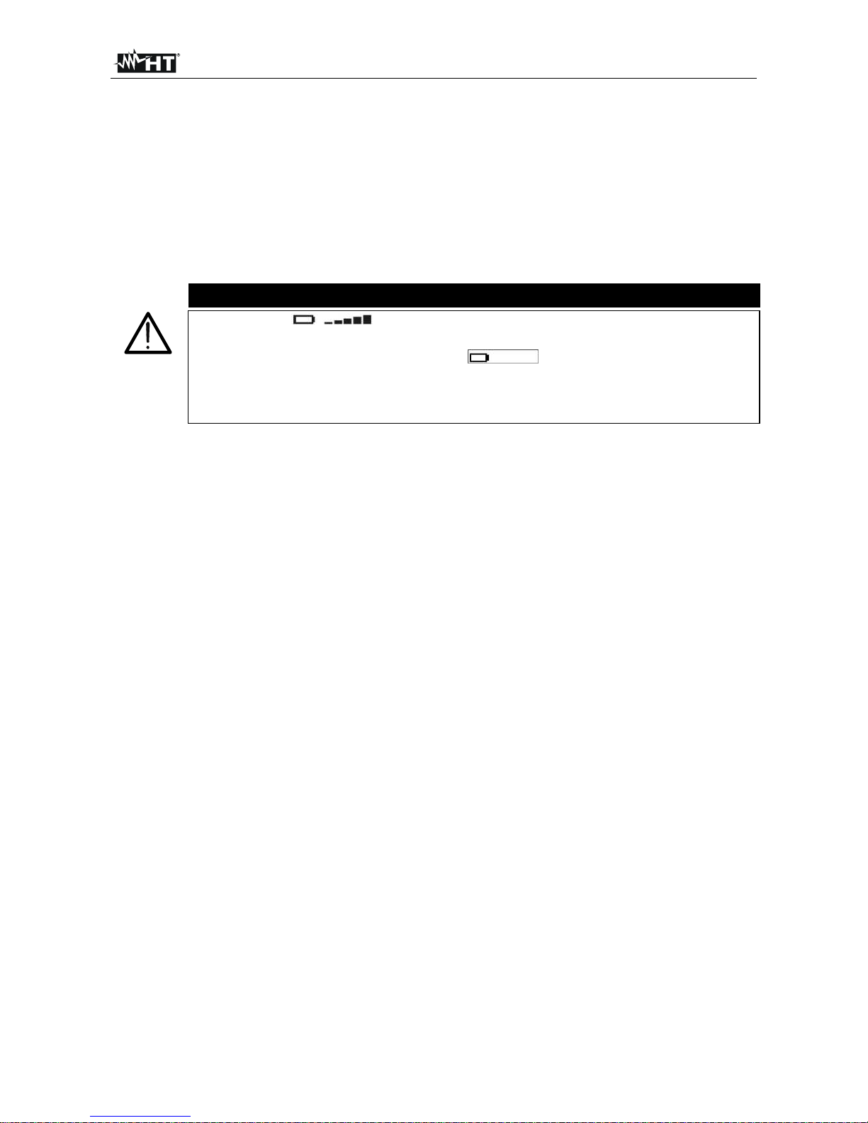
CAUTION
The symbol indicates the charge level. When there are five bars
next to the battery symbol, it means that batteries are fully charged; a
decrease in the number of bars to " " indicates that the batteries
are almost low. In this case, interrupt tests and replace the batteries
according to the indications given in § 11.2. The instrument is able to keep
data stored also with no batteries.
1.3. AFTER USE
When measuring operations are completed, turn off the instrument by pressing and
holding the ON/OFF key for a few seconds. Should the instrument remain unused for a
long time, remove batteries and follow the indications given in § 3.4.
1.4. OVERVOLTAGE CATEGORIES - DEFINITIONS
Standard IEC/EN61010-1 (Safety requirements for electrical equipment for measurement,
control and laboratory use, Part 1: General requirements) defines what a measurement
category (usually called “overvoltage category”) is. At § 6.7.4: Measuring circuits it says:
Circuits are divided into the following measurement categories:
Measurement category IV is for measurements performed at the source of the low-
voltage installation.
Examples are electricity meters and measurements on primary overcurrent protection
devices and ripple control units
.
Measurement category III is for measurements performed in the building installation.
Examples are measurements on distribution boards, circuit breakers, wiring, including
cables, bus-bars, junction boxes, switches, socket-outlets in the fixed installation, and
equipment for industrial use and some other equipment, for example, stationary motors
with permanent connection to fixed installation
.
Measurement category II is for measurements performed on circuits directly
connected to the low voltage installation.
Examples are measurements on household appliances, portable tools and similar
equipment
.
Measurement category I is for measurements performed on circuits not directly
connected to MAINS
.
Examples are measurements on circuits not derived from MAINS, and specially
protected (internal) MAINS-derived circuits. In the latter case, transient stresses are
variable; for that reason, the norm requires that the transient withstand capability of the
equipment is made known to the user
.
Page 7
400 Series
EN - 6
2. GENERAL DESCRIPTION
2.1. INTRODUCTION
The instrument you purchased, if used in compliance with the instructions given in this manual,
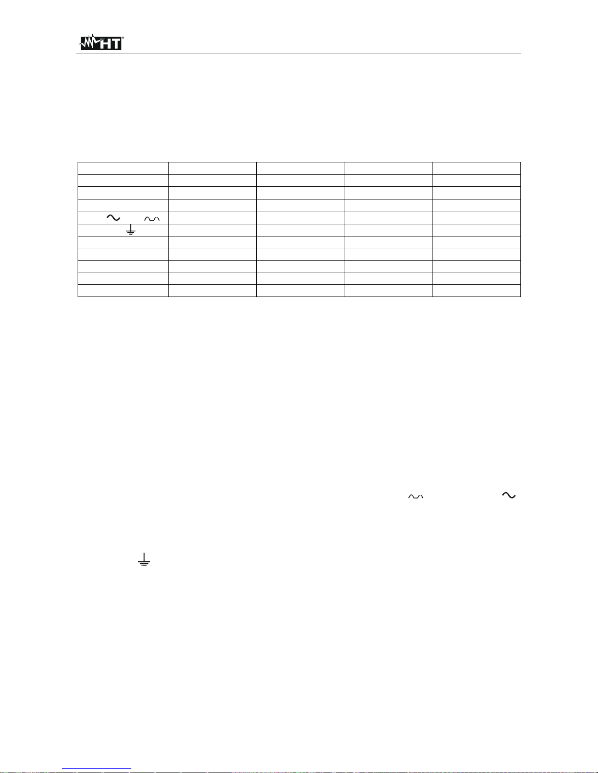
will guarantee accurate and reliable measures. This manual covers following products:
ISO410, SPEED418, COMBI419, COMBI420. The differences in model characteristics are
described in the following table:
Function ISO410 SPEED418 COMBI419 COMBI420
AUTO
LOW
M
RCD and
Ra 15mA
LOOP
123
AUX
LEAKAGE
POWER
Tab. 1: Characteristics of 400 Series models
2.2. INSTRUMENT OPERATION
The instrument can perform following tests (compatibly with the characteristics described
in the table above):
AUTO Test which automatically performs the following test sequence: total
earth resistance through socket, tripping time of the differential switch,
insulation resistance between phase and earth.
LOW Continuity test of earth conductors, protective conductors and equipotential
conductors with test current higher than 200mA and open circuit voltage
between 4V and 24V.
M Insulation resistance measurement with a direct test voltage of 50V, 100V,
250V, 500V or 1000V.
RCD Measurement of following parameters on A-type ( ) and AC-type ( )
general and/or selective differential switches: tripping time, tripping current,
contact voltage (Ut), total earth resistance (RA).
LOOP Measurement of line impedance and fault loop impedance with
calculation of the assumed fault current.
Ra 15mA
Measurement of total earth resistance with 15mA without causing the
differential protections’ tripping.
123 Indication of the phase sequence.
AUX Measurement of the environmental parameters (temperature, humidity, air
speed, lighting and noise level) by means of optional probes.
LEAKAGE Function for measuring leakage current in real time by means of an
(optional) HT96U clamp.
POWER Real-time displaying the values of the electrical quantities in a single-
phase system and the harmonic analysis of voltage and current up to
the 49
th
harmonic with THD% calculation.
Page 8
400 Series
EN - 7
3. PREPARATION FOR USE
3.1. INITIAL CHECKS
Before shipment, the instrument’s electronics and mechanics have been carefully checked.
All possible precautions have been taken in order for the instrument to be delivered in
optimum conditions. However, we recommend rapidly checking the instrument in order to
detect possible damage occurred during transport. Should you detect anomalies, please
immediately contact the dealer.
It is also recommended to check that the package contains all parts indicated in § 12.5. In
case of discrepancies, please contact the dealer. Should it be necessary to return the
instrument, please follow the instructions given in § 13.
3.2. INSTRUMENT POWER SUPPLY
The instrument is battery supplied. For battery type and life, see § 12.3.
The symbol "
" indicates the charge level. When there are five bars next to the
battery symbol, it means that batteries are fully charged; a decrease in the number of bars
to "
" indicates that the batteries are almost low. In this case, interrupt tests and
replace the batteries according to the indications given in § 11.2.
The instrument is able to keep data stored also with no batteries.
For the insertion of batteries, follow the indications given in § 11.2.
The instrument is provided with advanced algorithms to maximize the batteries’ life. In
particular:
the instrument automatically turns off the display’s back lighting after ca. 5 seconds.
in order to increase battery autonomy, should the voltage supplied by batteries be too
low, the instrument disables the display’s back-lighting function.
3.3. CALIBRATION
The instrument’s technical specifications are those described in this manual. Its
performance is warranted for one year from the date of purchase.
3.4. STORAGE
In order to guarantee precise measures, after the instrument has remained stored for a
long time under extreme environmental conditions, wait for the instrument to return to
normal conditions (see the environmental specifications listed in § 12.4.1).
Page 9
400 Series
EN - 8
4. OPERATION DESCRIPTION
4.1. INSTRUMENT DESCRIPTION
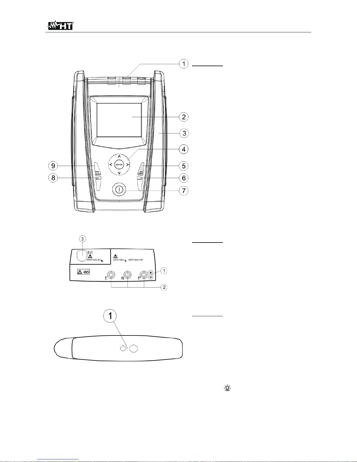
CAPTION:
1. Inputs
2. Display
3. Connector for optoisolated cable
4. ,, , / ENTER key
5. GO/STOP key
6. SAVE key
7. ON/OFF key
8. HELP key
9. ESC/MENU key
Fig. 1: Description of the front part of the instrument
CAPTION:
1. Connector for remote probe
2. E, N, P inputs
3. In1 input
Fig. 2: Description of the upper part of the instrument
CAPTION:
1. Connector for optoisolated cable
Fig. 3: Description of the instrument’s side
4.2. BACKLIGHTING
During instrument operation, a further short pressing of the key turns on the display’s
backlighting (if battery voltage level is sufficiently high). In order to preserve battery efficiency,
backlighting automatically turns off after ca. 20 seconds.
A frequent use of back lighting reduces the batteries’ life.
Page 10
400 Series
EN - 9
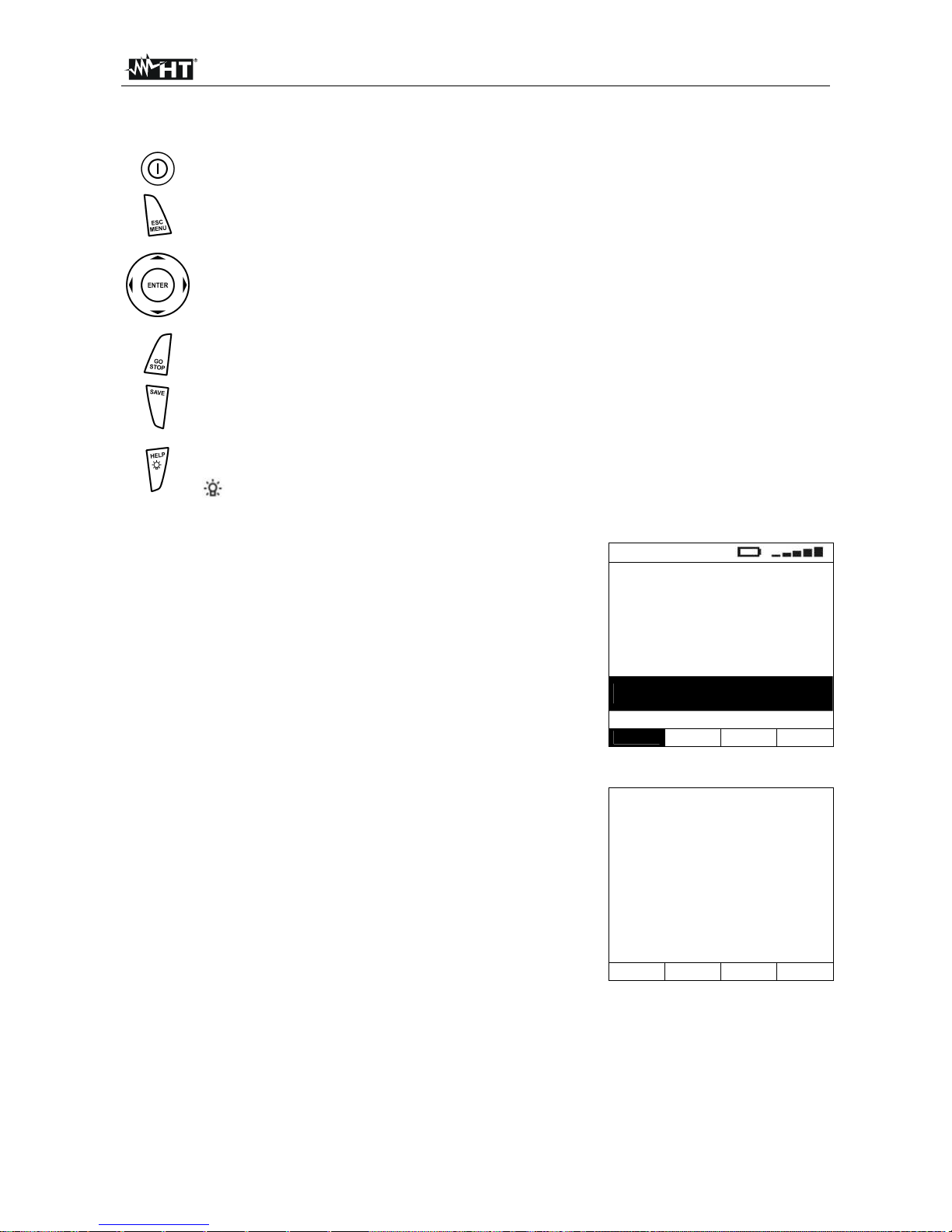
4.3. KEYBOARD DESCRIPTION
The keyboard includes following keys:
ON/OFF key to switch on/off the instrument
ESC key to exit the selected menu without confirming
MENU key to activate menu management
keys to move the cursor through the different screens in order to
select the desired programming parameters
ENTER key to confirm the modifications and the selected programming
parameters and to select the function from the menu
GO key to start measurements
STOP key to stop measurements
SAVE key to save the measured values
HELP key (long pressure) to display an indicative scheme of the connections
between the instrument and the system being tested in the function set
key (short pressure) to turn on the display’s backlighting
4.4. DISPLAY DESCRIPTION
The display is a graphic module with a resolution of 128 x 128
dots. The display’s first line indicates the type of active
measurement and the battery charge indicator
LOW
-.--
R+ R-
-.-- -.--
--- mA --- mA
Measuring…
AUTO
1.00
0.12
Func Lim CAL
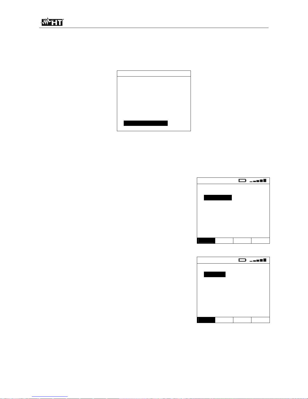
4.5. INITIAL SCREEN
When turning on the instrument the instrument displays an
initial screen for a few seconds. It displays the following:
the instrument’s model
the manufacturer’s name
the serial number (SN:) of the instrument
the firmware version (FW:) in the instrument's memory
the date of calibration (Calibration:).
COMBI 420
HT ITALIA
SN: 12345678
FW: 1.20
Calibration:
02/03/2012
Then, the instrument switches to the last function selected.
Page 11
400 Series
EN - 10
5. MAIN MENU
Pressing the MENU/ESC key in any allowable condition of the instrument displays the
following screen, in which the instrument may be set, the saved measures can be
displayed and the desired measuring function may be set.
MENU
AUTO : Ra, RCD, M
LOW
: continuity
M
: insulation
RCD : RCD test
LOOP : impedance
Ra : earth res.
123 : PH sequence
AUX : environment
LEAK : leakage curr.
PWR : analyzer
SET : settings
MEM : memory
5.1. AUTO ÷ PWR
By selecting one of the measurements listed between AUTO and PWR with the cursor,
compatibly with the characteristics reported in Tab. 1, and confirming selection with
ENTER, the desired measurement is accessed.
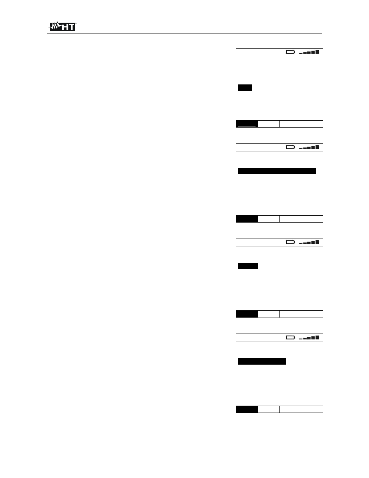
5.2. SET – INSTRUMENT SETTINGS
Move the cursor to SET by means of the arrow keys (,)
and confirm with ENTER. Subsequently, the displays shows
the screen which allows accessing the various instrument
settings.
The settings will remain valid also after switching off the
instrument.
SET
Language
Auto power off
Nominal V
Frequency
System
VAL
5.2.1. Language
Move the cursor to Language by means of the arrow keys
(,) and confirm with ENTER. Subsequently, the displays
shows the screen which allows setting the instrument
language.
Select the desired option by means of the arrow keys (,).
To store settings, press the ENTER key, to exit the changes
made, press the ESC key.
LNG
Italiano
English
Español
Deutsch
Français
Svenska
Norsk
Dansk
VAL
Page 12
400 Series
EN - 11
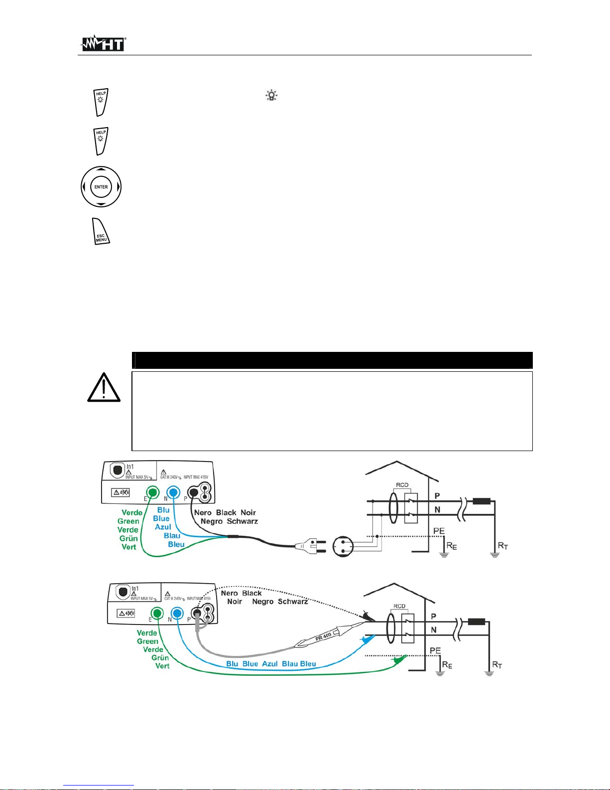
5.2.2. Auto power off
Move the cursor to Auto power off by means of the arrow
keys (,) and confirm with ENTER. Subsequently, the
displays shows the setting screen which allows
enabling/disabling the auto power off of the instrument after a
period of 5 minutes inactivity.
Select the desired option by means of the arrow keys (,).
To store settings, press the ENTER key, to exit the changes
made, press the ESC key.
OFF
ON 5 min
OFF
VAL
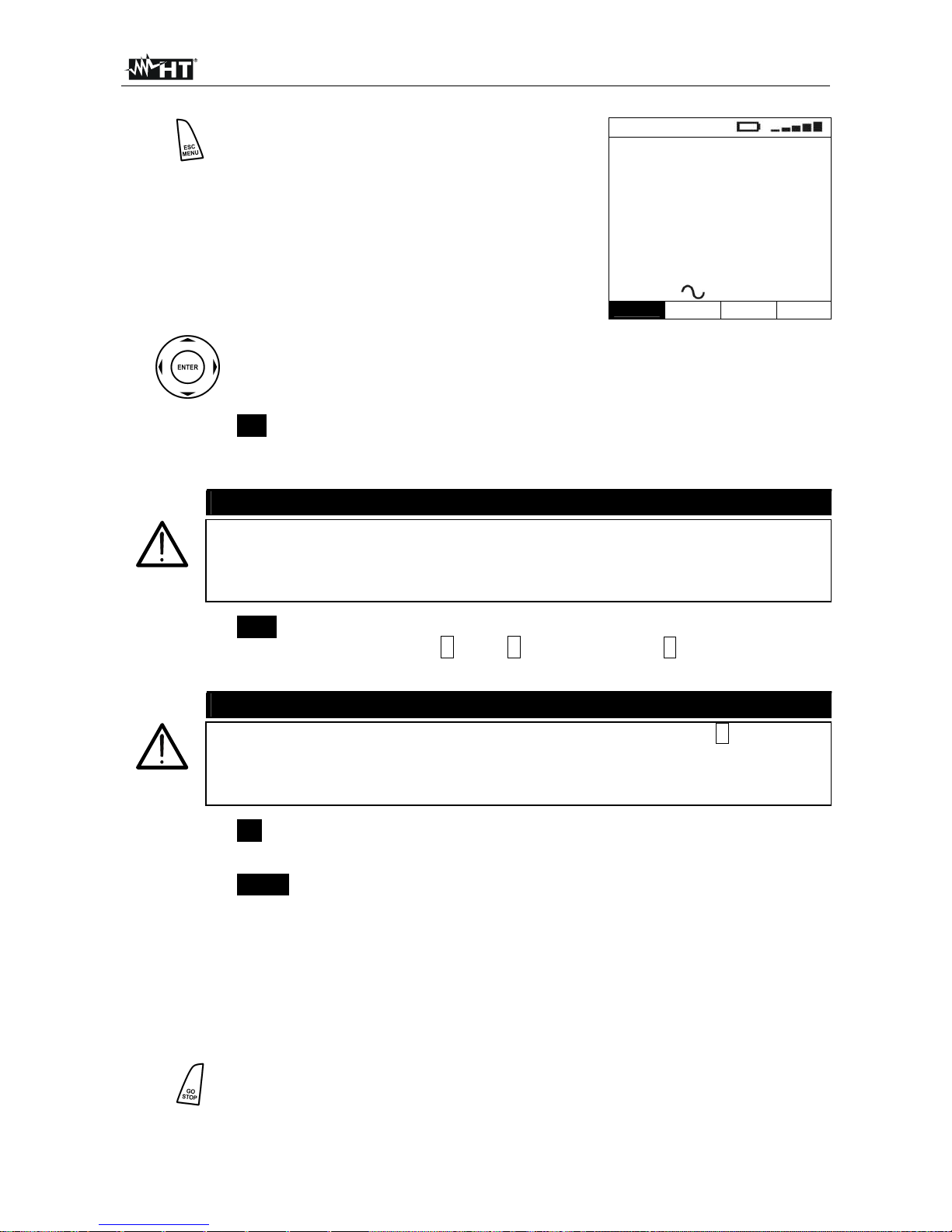
5.2.3. Nominal voltage
Move the cursor to Nominal V by means of the arrow keys
(,) and confirm with ENTER. Subsequently, the displays
shows the screen which allows setting the value of the
voltage to be used for calculating the prospective short-circuit
current.
Select the desired option by means of the arrow keys (,).
To store settings, press the ENTER key, to exit the changes
made, press the ESC key.
VNOM
Vp-n=230V Vp-p=400V
Vp-n=240V Vp-p=415V
VAL
5.2.4. Frequency
Move the cursor to Frequency by means of the arrow keys
(,) and confirm with ENTER. Subsequently, the displays
shows the screen which allows setting the value of the mains
frequency.
Select the desired option by means of the arrow keys (,).
To store settings, press the ENTER key, to exit the changes
made, press the ESC key.
FREQ
50 Hz
60 Hz
VAL
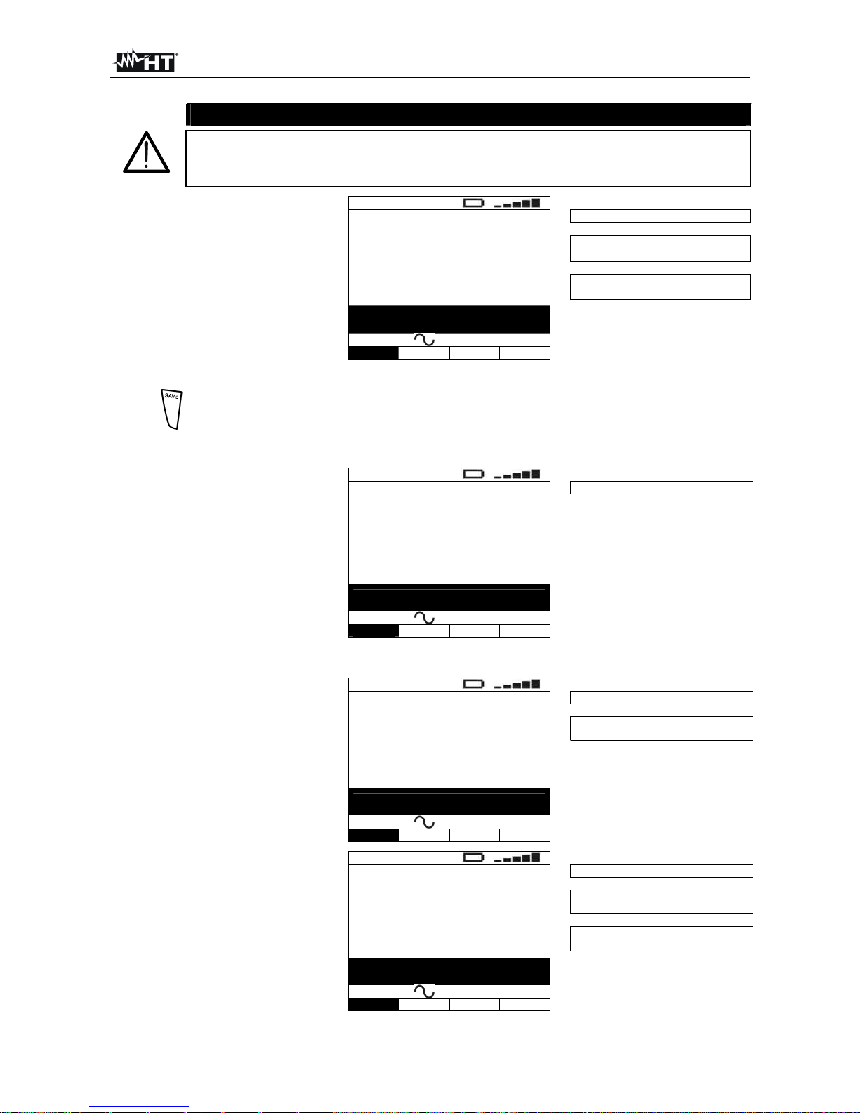
5.2.5. System
Move the cursor to System by means of the arrow keys
(,) and confirm with ENTER. Subsequently, the display
shows the screen which allows selecting the type of electric
power supply system.
Select the desired option by means of the arrow keys (,).
To store settings, press the ENTER key, to exit the changes
made, press the ESC key.
SYS
TT/TN system
IT system
VAL
5.3. MEM
By selecting MEM with the cursor and confirming selection with ENTER, the memory
management is accessed (§ 9).
Page 13
400 Series
EN - 12
6. ELECTRICAL SYSTEM TEST
Press (short pressure) the key to activate the display’s backlighting should it
be difficult to read the display.
Press (long pressure) the HELP key to display an indicative scheme of the
connections between the instrument and the system being tested in the function set
Should more help screens be available for the same function, use the and
keys to scroll them.
Press the ESC key to exit the on-line help and go back to the selected
measurement.
6.1. AUTO
This function enables performing an automatic sequence of tests, including the main tests
regarding the electric safety of a system, i.e.:
measurement of earth resistance through socket-outlet
measurement of RCD tripping time
measurement of insulation resistance between phase and earth
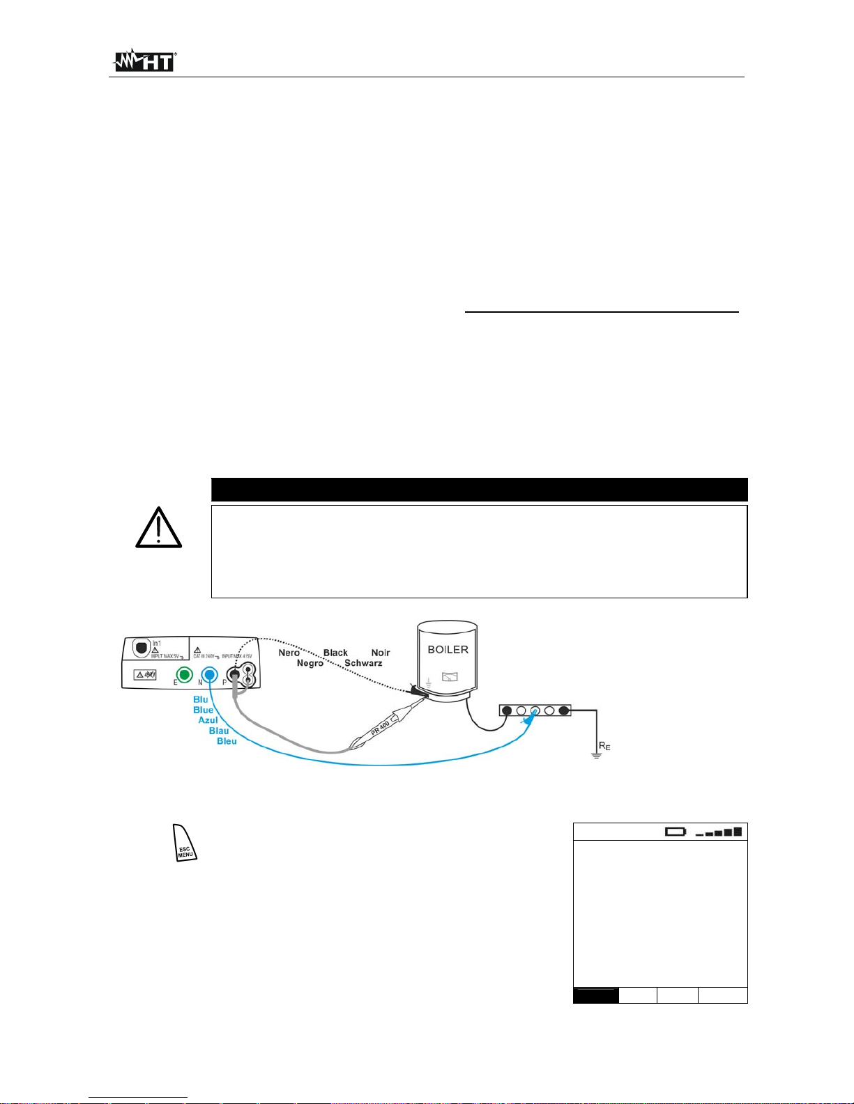
CAUTION
Testing the RCD’s tripping time causes the RCD’s tripping. Therefore, check
that there are NO users or loads connected downstream of the RCD
being tested which could be damaged by a system downtime.
Disconnect all loads connected downstream of the RCD as they could
produce leakage currents further to those produced by the instrument, thus
invalidating the results of the test
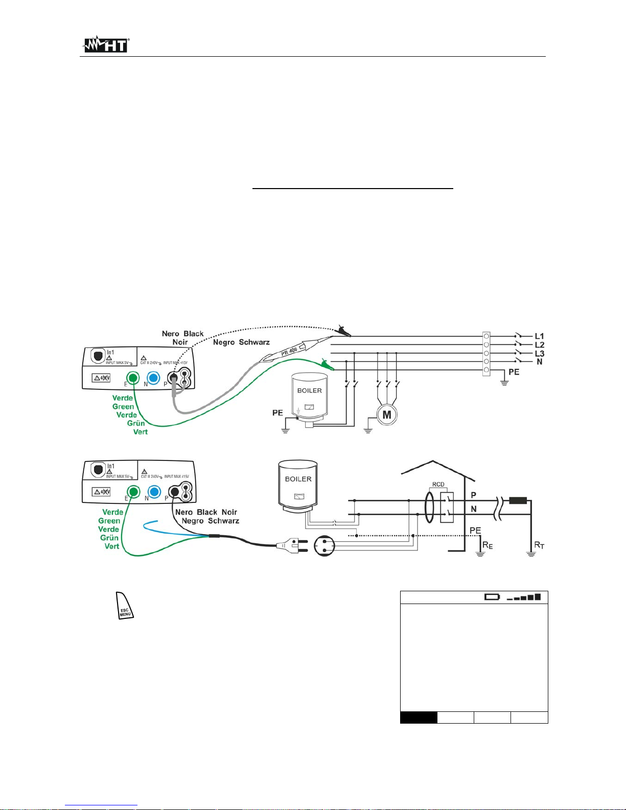
Fig. 4: Instrument connection through shuko cable
Fig. 5: Instrument connection by means of single cables and remote probe
Page 14
400 Series
EN - 13
1.
Press the MENU key, move the cursor to
AUTO in the main menu by means of the
arrow keys (,) and confirm with ENTER.
Subsequently the instrument displays a screen
similar to the one reported here to the side.
AUTO
Ra = ----
Trcd = ----ms
RP-Pe = ----M
30mA
50V 500V
IdN RCD UL VNom
2.
Use the , keys to select the parameter to be modified, and the , keys
to modify the parameter value.
It is not necessary to confirm the selection with ENTER.
IdN
The virtual IdN key allows setting the nominal value of the RCD’s
tripping current, which may be: 10mA, 30mA, 100mA, 300mA,
500mA, 650mA
CAUTION
Make sure to select the correct value when setting the RCD’s test current. If
setting a current higher than the nominal current of the device being tested,
the RCD would be tested at a current higher than the correct one, thus
facilitating a faster tripping of the switch
RCD
The virtual RCD key enables the selection of the RCD type, which
may be: AC, AC S , A, A S (the options A, A S are not available if
the electrical system set is IT)
CAUTION
When activating the test option for selective RDCs (symbol S), the time
interval between the tests is 60 seconds (30 seconds for tests with ½IdN).
The instrument display shows a timer indicating the time remaining before
the instrument can automatically perform the test.
UL
The virtual UL key allows setting the limit value of contact voltage
for the system being tested, which may be: 25V, 50V
VNom
The virtual VNom allows setting the value of test voltage for insulation
measurement, which may be: 50V, 100V, 250V, 500V, 1000V
3. Insert the green, blue and black connectors of the three-pin shuko cable into the
corresponding input leads E, N and P of the instrument. As an alternative, use the
single cables and apply the relevant alligator clips to the free ends of the cables. It is
also possible to use the remote probe by inserting its multipolar connector into the
input lead P. Connect the shuko plug, the alligator clips or the remote probe to the
electrical mains according to Fig. 4 and Fig. 5
4.
Press the GO/STOP key on the instrument or the START key on remote
probe. The instrument will start the automatic test sequence.
Page 15
400 Series
EN - 14
CAUTION
If message “Measuring…” appears on the display, the instrument is
performing measurement. During this whole stage, do not disconnect the
test leads of the instrument from the mains.
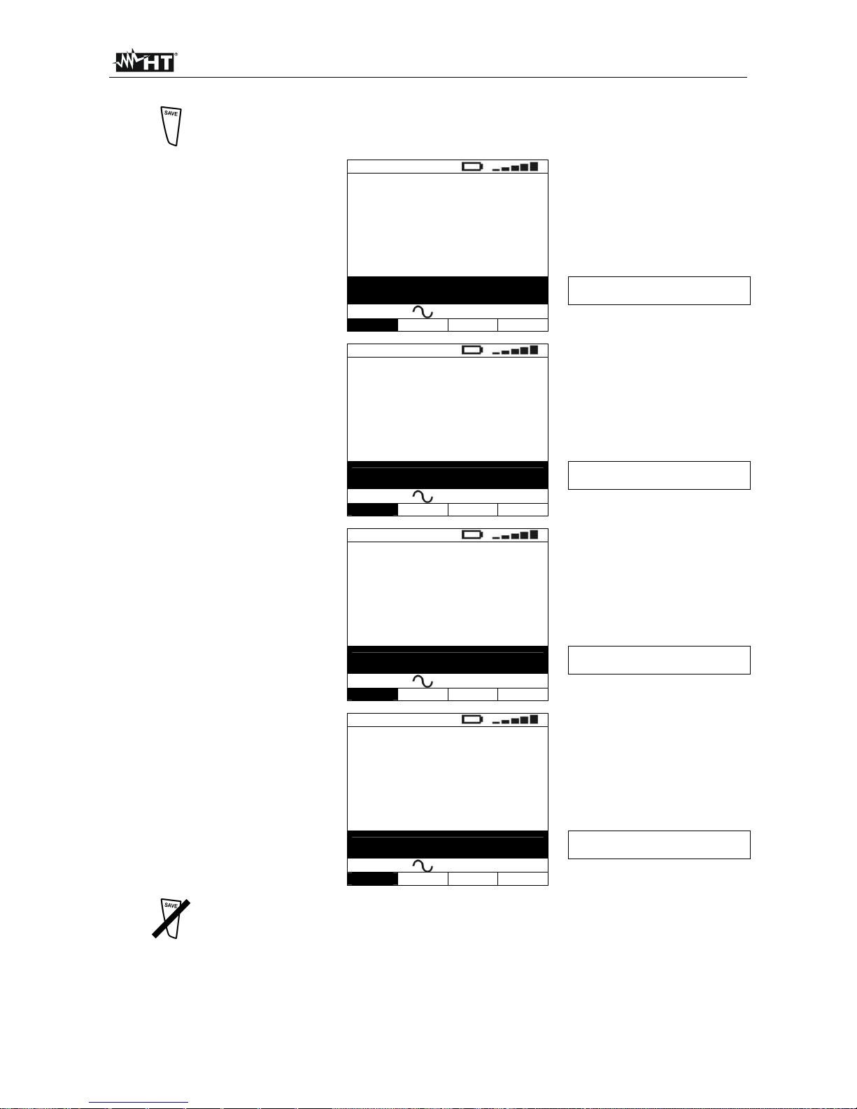
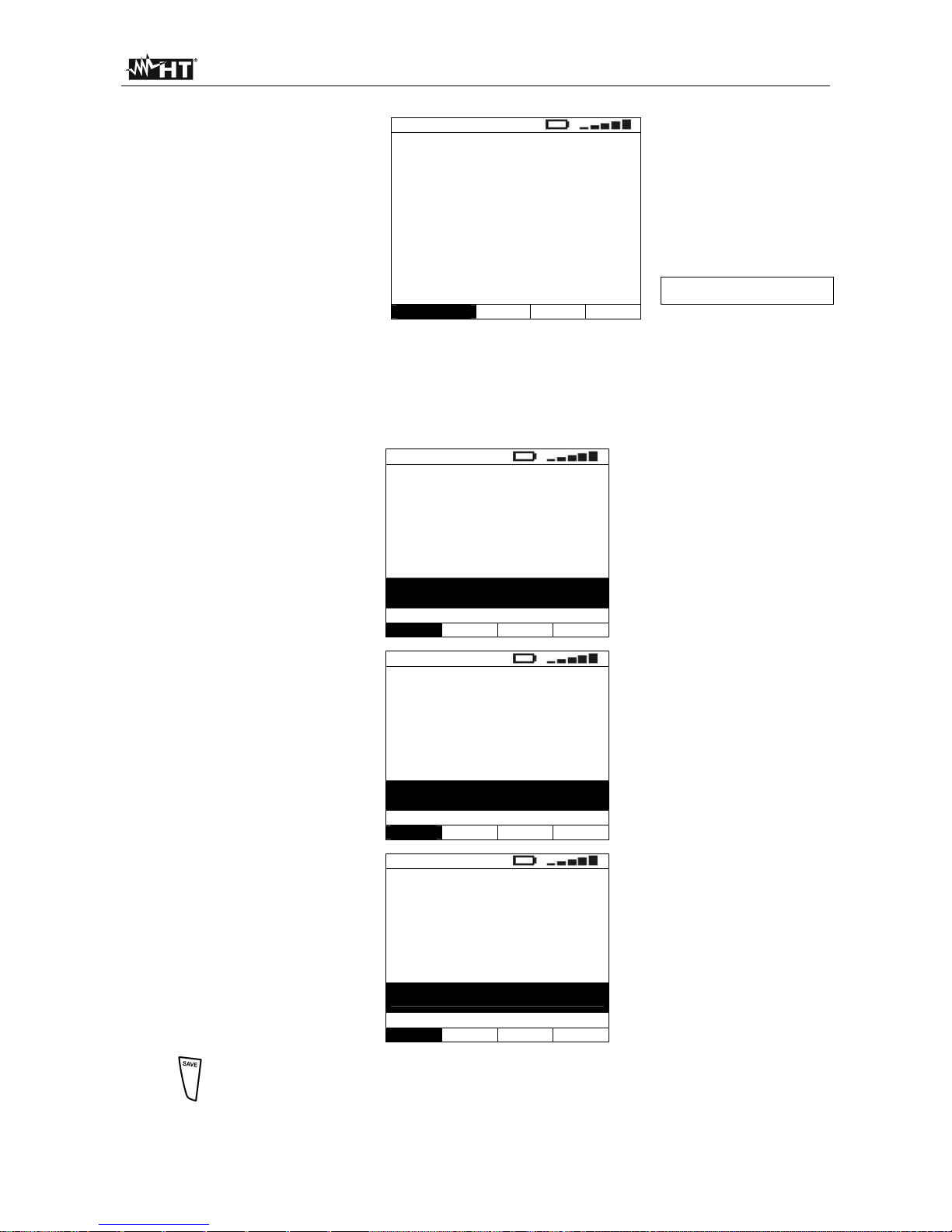
5. Once the test is completed, if
all measured values are
correct, the instrument gives
a double acoustic signal and
displays the message “OK”,
which signals that the test
has been completed
successfully, and a screen
similar to the one reported
here to the side
AUTO
Ra = 49.1
Trcd = 24ms
RP-Pe > 999M
Value of earth resistance
Value of the RCD’s tripping time
Value of the phase-to-earth
insulation resistance
OK
30mA 50V 500V
IdN RCD UL VNom
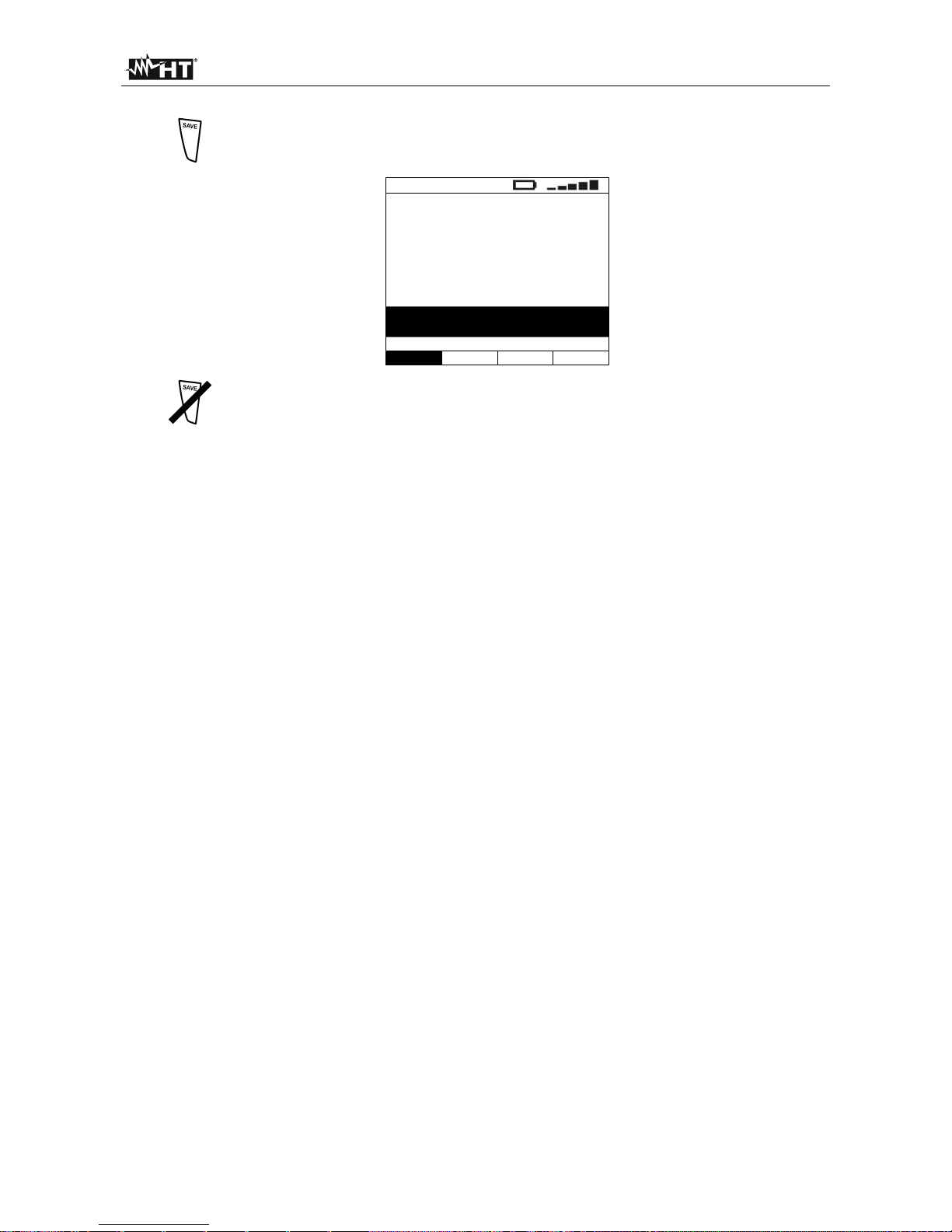
6.
The results displayed can be saved by pressing the SAVE key twice or the
SAVE key and, subsequently, the ENTER key (§ 9.1)
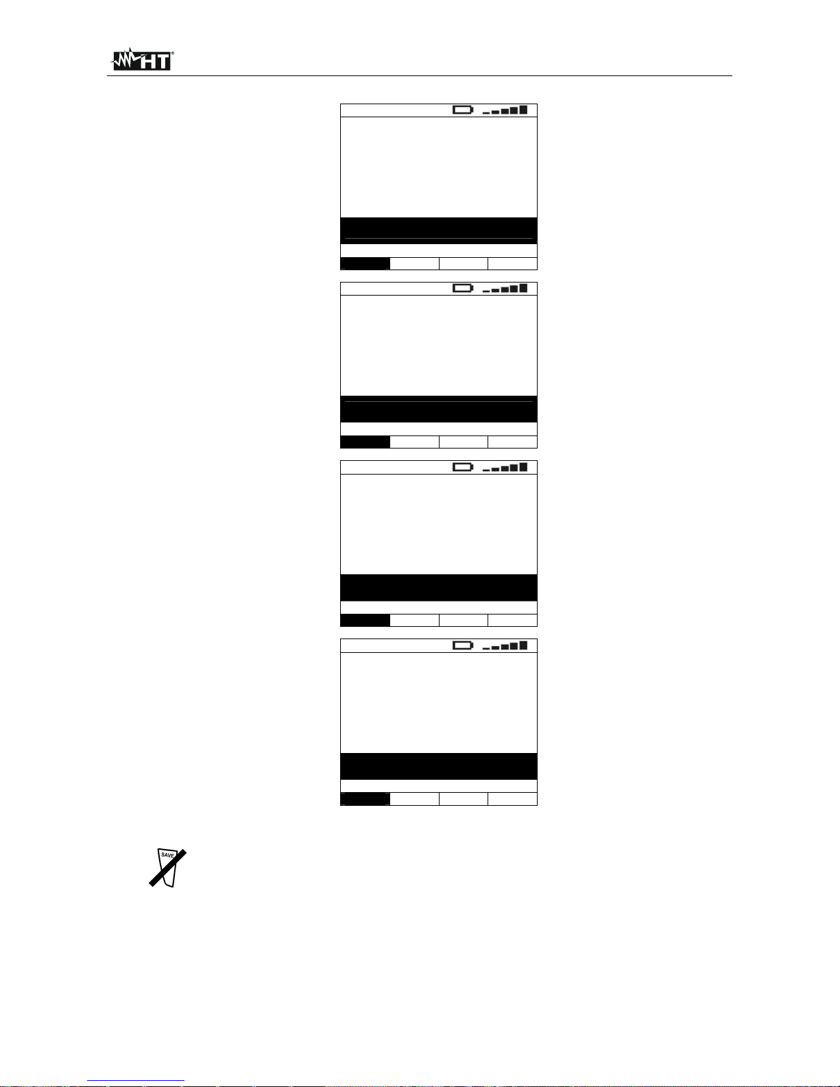
6.1.1. Description of anomalous results
1. The instrument detects a
resistance higher than the
calculated limit value UL/IdN
(1666Ω @ UL=50V and
IdN=30mA) or higher than
the full scale value. A screen
similar to the one reported
here to the side is displayed,
a long acoustic signal is
given and the automatic test
is interrupted
AUTO
Ra = 1789
Trcd = ----ms
RP-Pe = ----M
Value of earth resistance
NOT OK
30mA 50V 500V
IdN RCD UL VNom
2. The instrument detects that
the RCD trips out of its limit
time, or does not trip at all.
A
screen similar to the one
reported here to the side is
displayed, a long acoustic
signal is given and the
automatic test is interrupted
AUTO
Ra = 1789
Trcd > 999ms
RP-Pe = ----M
Value of earth resistance
Value of the RCD’s tripping time
NOT OK
30mA 50V 500V
IdN RCD UL VNom
3. If the measured phase-toearth insulation value is
lower than the set limit, the
instrument displays a screen
similar to the one reported
here to the side and gives a
long acoustic signal
AUTO
Ra = 1789
Trcd > 999ms
RP-Pe = 0.01M
Value of earth resistance
Value of the RCD’s tripping time
Value of the phase-to-earth
insulation resistance
NOT OK
30mA 50V 500V
IdN RCD UL VNom
Page 16
400 Series
EN - 15
4.
The results displayed can be saved by pressing the SAVE key twice or the
SAVE key and, subsequently, the ENTER key (§ 9.1)
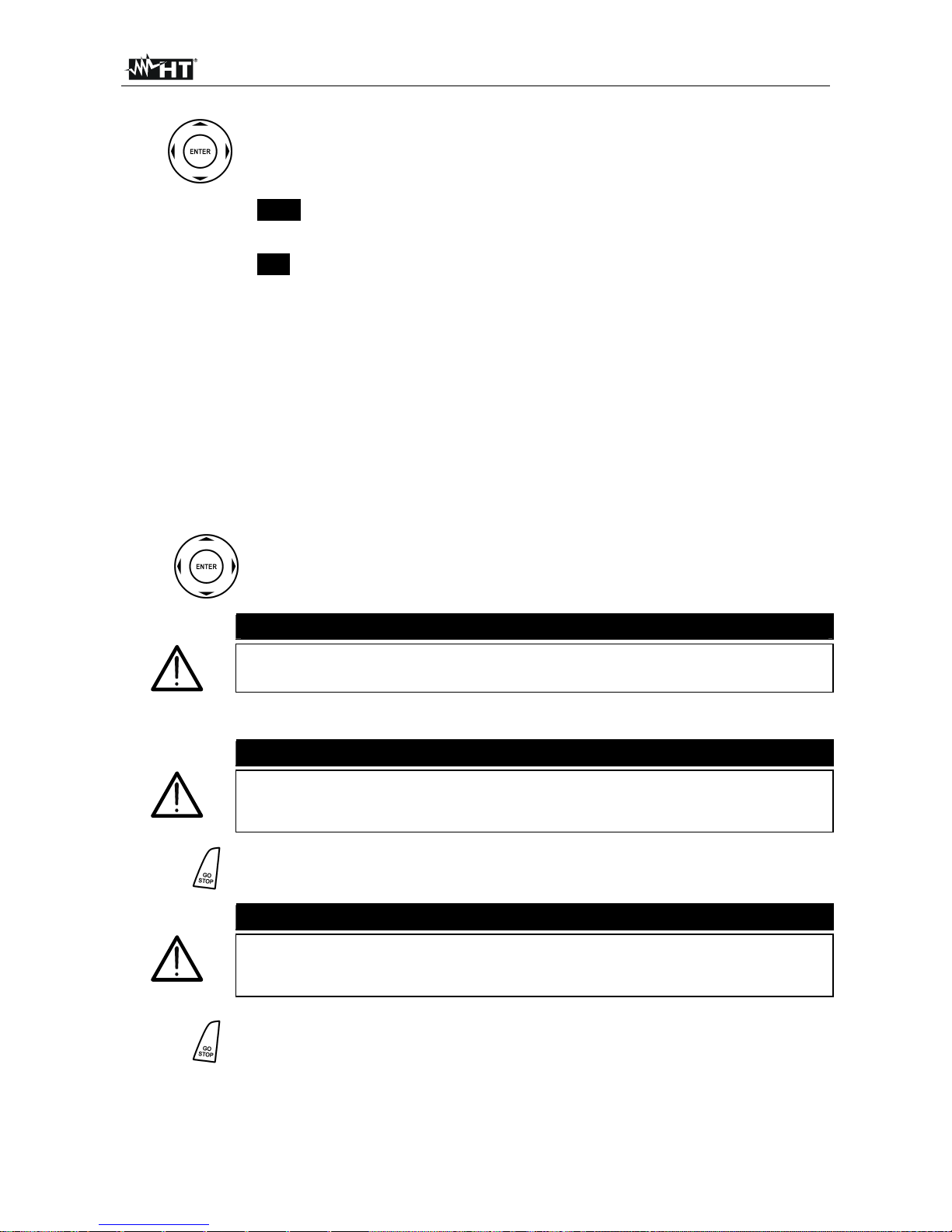
5. If the instrument detects that
the phase and neutral leads
are inverted, the message
reported here to the side is
displayed. Rotate the shuko
plug or check the connection
of the single cables
AUTO
Ra = ----
Trcd = ----ms
RP-Pe = ----M
REVERSE P-N
The phase and neutral conductors
are inverted
30mA 50V 500V
IdN RCD UL VNom
6. If the instrument detects that
the phase and earth leads
are inverted, the message
reported here to the side is
displayed. check the
connection of the cables
AUTO
Ra = ----
Trcd = ----ms
RP-Pe = ----M
REVERSE P-PE
The phase and earth conductors are
inverted
30mA 50V 500V
IdN RCD UL VNom
7. If the instrument detects a
phase-to-neutral voltage and
a phase-to-earth voltage
lower than the limit, the
message reported here to
the side is displayed. Check
that the system being tested
is energized
AUTO
Ra = ----
Trcd = ----ms
RP-Pe = ----M
Low voltage
Insufficient voltage
30mA 50V 500V
IdN RCD UL VNom
8. If the instrument detects a
phase-to-neutral voltage or a
phase-to-earth voltage higher
than the limit, the message
reported here to the side is
displayed. Check that the
instrument is not phase-tophase connected
AUTO
Ra = ----
Trcd = ----ms
RP-Pe = ----M
High voltage
High voltage detected
30mA 50V 500V
IdN RCD UL VNom
9.
The previous anomalous results cannot be saved
Page 17
400 Series
EN - 16
6.2. LOWOHM: CONTINUITY TEST OF EARTH LEADS WITH 200mA
This function is performed in compliance with standard IEC/EN61557-4 and allows
measuring the resistance of protective and equipotential conductors. The following
operating modes are available:
CAL compensation of the resistance of the cables used for measurement. The
instrument automatically subtracts the value of cable resistance from the
measured resistance value. It is therefore necessary that this value is measured
(by means of the CAL function) each time the test cables are changed or
extended
AUTO the instrument performs two measurements with inverted polarity and displays
the average value of the two measures. Recommended mode for continuity test
R+ measurement with positive polarity and with the possibility of setting a test
duration time. In this case, the operator may set a measuring time long enough
to be able to move the protective conductors while the instrument is performing
the test, in order to detect a possible bad connection
R- measurement with negative polarity and with the possibility of setting a test
duration time. In this case, the operator may set a measuring time long enough
to be able to move the protective conductors while the instrument is performing
the test, in order to detect a possible bad connection.
CAUTION
The continuity test is performed by supplying a current higher than
200mA in case the resistance is not higher than ca. 10 (including
resistance of the test cables saved in the instrument as offset after
performing the calibration procedure). For higher resistance values, the
instrument performs the test with a current lower than 200mA.
Fig. 6: Instrument connection by means of single cables and remote probe
1.
Press the MENU key, move the cursor to
LOW in the main menu by means of the arrow
keys (,) and confirm with ENTER.
Subsequently the instrument displays a screen
similar to the one reported here to the side.
LOW
----
R+ R-
---- ----
---mA ---mA
CAL
4.00
----
Func Lim CAL
Page 18
400 Series
EN - 17
2.
Use the , keys to select the parameter to be modified, and the ,
keys to modify the parameter value.
It is not necessary to confirm the selection with ENTER.
Func
The virtual Func key allows setting the measuring mode of
the instrument, which may be: CAL, AUTO, R+, R-
Lim
The virtual Lim key allows setting the maximum continuity
limit, which may have the following values: 1.00, 2.00,
3.00, 4.00, 5.00
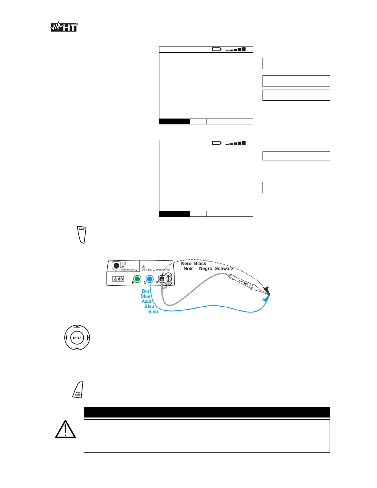
3. Insert the blue and black connectors of the single cables into the corresponding input
leads N and P of the instrument. Apply the relevant alligator clips to the free ends of
the cables. It is also possible to use the remote probe by inserting its multipolar
connector into the input lead P.
4. Should the length of the cables provided be insufficient for the measurement to be
performed, extend the blue cable.
5.
Select the CAL mode to compensate the resistance of the cables used for measuring
according to the instructions given in § 6.2.1.
6.
Use the arrow keys , to select the virtual Func key and set the desired
test mode by means of the arrow keys , .
It is not necessary to confirm the selection with ENTER.
CAUTION
Before connecting the test leads, make sure that there is no voltage at
the ends of the conductor to be tested.
7. Connect the test leads to the ends of the conductor to be tested as in Fig. 6.
CAUTION
Always make sure, before any test, that the compensation resistance
value of the cables is referred to the cables currently used. In case of
doubt, repeat the cable calibration procedure as in 6.2.1.
8.
Press the GO/STOP key on the instrument or the START key on remote
probe. The instrument will start the measurement.
CAUTION
If message “Measuring…” appears on the display, the instrument is
performing measurement. During this whole stage, do not disconnect
the test leads of the instrument from the conductor under test.
9.
In case the R+ or R- mode has been selected, pressing the GO/STOP
key on the instrument or the START key on remote probe stops the test
before the set time has elapsed.
Page 19
400 Series
EN - 18
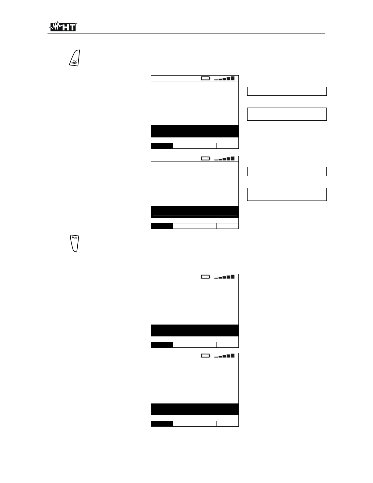
10. By using the AUTO mode,
once test is completed, in
case the average value
between R+ and R- is lower
than the set limit, the
instrument gives a double
acoustic signal which signals
the positive result of the test
and displays a screen similar
to the one reported here to
the side
LOW
0.25
R+ R-
0.26 0.24
212mA 213mA
Average value between R+
and R-
Values of the test currents for
R+ and R-
Values of R+ and R-,
respectively
AUTO
4.00
0.21
Func Lim CAL
11. By using the R+ or R- mode,
once test is completed, in
case the detected value is
lower than the set limit, the
instrument gives a double
acoustic signal which signals
the positive result of the test
and displays a screen similar
to the one reported here to
the side
LOW
0.25
212mA 1s
Value of resistance R+ (or R-)
Values of test current and test
time
R+
4.00
1s
0.21
Func Lim Temp CAL
12.
The results displayed can be saved by pressing the SAVE key twice or
the SAVE key and, subsequently, the ENTER key (§ 9.1)
6.2.1. CAL mode
Fig. 7: Calibration of single cables and remote probe
1.
Use the arrow keys , to select the virtual Func key and set the CAL test
mode by means of the arrow keys , .
It is not necessary to confirm the selection with ENTER.
2. Short the leads of the measurement cables as in Fig. 7 making sure that the
conductive parts of alligator clips are well in contact.
3.
Press the GO/STOP key on the instrument or the START key on remote
probe. The instrument starts the calibration procedure of the cables
immediately followed by the verification of the compensated value.
CAUTION
If message “Measuring…” appears on the display, the instrument is
performing measurement. If message “Waiting verify” appears on the
display, the instrument is verifying the calibrated value. During this whole
stage, do not unshort the test leads of the instrument.
Page 20
400 Series
EN - 19
4. Once calibration is comple-
ted, in case the detected
value is lower than 5, the
instrument gives a double
acoustic signal which signals
the positive result of the test
and displays a screen similar
to the one reported here to
the side
LOW
----
R+ R-
---- ----
---mA ---mA
CAL
4.00
0.21
Value of the calibrated
resistance
Func Lim CAL
5. In order to delete the compensation resistance value of the cables, it is necessary to
perform a cable calibration procedure with a resistance higher than 5 at test leads
(e.g. with open test leads).
6.2.2. Description of anomalous results
1. By using the AUTO, R+ or R-
mode, in case the detected
value is higher than the set
limit, the instrument gives a
long acoustic signal and
displays a screen similar to
the one reported here to the
side
LOW
5.92
R+ R-
5.92 5.91
210mA 210mA
R > LIM
AUTO
4.00
0.21
Func Lim CAL
2. By using the AUTO, R+ or R-
mode, in case the detected
value is higher than the full
scale, the instrument gives a
long acoustic signal and
displays a screen similar to
the one reported here to the
side
LOW
>99.9
R+ R >99.9 >99.9
---mA ---mA
I < 200mA
AUTO
4.00
0.21
Func Lim CAL
3. By using the AUTO, R+ or R-
mode, if the instrument
detects a resistance which
prevents a current of 200mA
to circulate, it gives a long
acoustic signal and displays
a screen similar to the one
reported here to the side
LOW
20.0
R+ R-
20.0 20.0
157mA 157mA
I < 200mA
AUTO
4.00
0.21
Func Lim CAL
4.
The results displayed can be saved by pressing the SAVE key twice or the
SAVE key and, subsequently, the ENTER key (§ 9.1)
Page 21
400 Series
EN - 20
5. If the instrument detects a
voltage value higher than
10V at the input leads, the
screen reported here to the
side is displayed
LOW
----
R+ R-
---- ----
---mA ---mA
Vin > Vlim
AUTO
4.00
0.21
Func Lim CAL
6. In case it was detected that
the calibrated resistance is
higher than the measured
resistance increased by
0.05 (R
CAL>RMEAS
+0.05),
the instrument gives a long
acoustic signal and displays
a screen similar to the one
reported here to the side
LOW
0.00
R+ R-
0.00 0.00
214mA 214mA
CAL > RES
AUTO
4.00
0.21
Func Lim CAL
7. By using the CAL mode, if
the instrument detects a
resistance higher than 5 at
input leads, a screen similar
to the one reported here to
the side is displayed, and the
instrument remains in the
condition of no resistance
calibrated
LOW
----
R+ R-
---- ----
---mA ---mA
Reset value
CAL
4.00
0.21
Func Lim CAL
8. By using the CAL mode,
verifying the calibrated value
at the end of the CAL
procedure, if the condition:
R
CAL
≤ R
MEAS
≤ R
CAL
+ 0.05Ω
is not met, a screen similar
to the one reported here to
the side is displayed, and the
instrument remains in the
condition of no resistance
calibrated
LOW
1.98
R+ R-
1.98 1.98
210mA 210mA
Not correct
CAL
4.00
----
Func Lim CAL
9.
The previous anomalous results cannot be saved
Page 22
400 Series
EN - 21
6.3. M: MEASUREMENT OF THE INSULATION RESISTANCE
This function is performed according to standard IEC/EN61557-2 and allows measuring
the insulation resistance between the active conductors and between each active
conductor and the earth. The following operating modes are available:
MAN in this mode, the test continues until the GO/STOP key on the instrument (or the
START key on the remote probe) is held. If the GO/STOP key (or the START
key of the remote probe) is pressed and immediately released, the test has a
duration of 2 seconds. Recommended mode for insulation test
TMR in this mode, the operator may set a measuring time long enough to be able to
move the test lead onto the conductors being tested, while the instrument is
performing the test. For the whole measurement duration, the instrument will
give a short acoustic signal every 2 seconds (in order to have a stable reading
of resistance, it is recommended to wait at least two acoustic signals before
moving the test lead to another conductor). While measuring, if insulation
resistance reaches a lower value than the set limit, the instrument will give a
continuous acoustic signal. To stop the test, press the GO/STOP key on the
instrument or the START key on the remote probe again.
Fig. 8: Instrument connection by means of single cables and remote probe
Fig. 9: Instrument connection through shuko cable
1.
Press the MENU key, move the cursor to M
in the main menu by means of the arrow keys
(,) and confirm with ENTER. Subsequently
the instrument displays a screen similar to the
one reported here to the side.
M
---M
----V ---s
MAN 500V 0.50M
Func VNom Lim
Page 23

400 Series
EN - 22
2.
Use the , keys to select the parameter to be modified, and the , keys
to modify the parameter value.
It is not necessary to confirm the selection with ENTER.
Func
The virtual Func key allows setting the measuring mode of the
instrument, which may be: MAN, TMR
VNom
The virtual VNom key allows setting the test voltage, which may
have the following values: 50V, 100V, 250V, 500V, 1000V
Lim
The virtual Lim key allows setting the minimum insulation limit,
which may have the following values: 0.05M, 0.10M, 0.23M,
0.25M, 0.50M, 1.00M, 100M
Temp
Only in TMR measuring mode, the virtual Temp key allows setting
the test duration time that may range between 10 and 999 seconds
3. We suggest setting the value of the voltage supplied while measuring and the
minimum limit to consider the measure correct according to the prescriptions of the
reference standard (§ 14.2).
4. Insert the green and black connectors of the single cables into the corresponding input
leads E and P of the instrument. Apply the relevant alligator clips to the free ends of
the cables. It is also possible to use the remote probe by inserting its multipolar
connector into the input lead P.
5. Should the length of the cables provided be insufficient for the measurement to be
performed, extend the green cable.
CAUTION
Before connecting the test leads, make sure that there is no voltage at the ends
of the conductors to be tested. Disconnect any cable not strictly involved in
measurement and moreover check that no cable is connected to In1 input.
6. Connect the test leads to the ends of the conductors to be tested as in Fig. 8 and Fig. 9.
7.
Press the GO/STOP key on the instrument or the START key on remote
probe. The instrument will start the measurement.
CAUTION
If message “Measuring…” appears on the display, the instrument is
performing measurement. During this whole stage, do not disconnect the
test leads of the instrument from the conductors under test, as the circuit being
tested could remain charged with a dangerous voltage due to the stray
capacitances of the system
8. Regardless of the operating mode selected, the instrument, at the end of each test,
applies a resistance to the output leads to discharge the stray capacitances in the
circuit
Page 24
400 Series
EN - 23
9.
In case the TMR mode has been selected, pressing the GO/STOP key on
the instrument or the START key on remote probe stops the test before the
set time has elapsed.
10. Should the measured value
be higher than the set limit,
the instrument gives a
double acoustic signal and
displays the message “OK”
which signals the positive
result of the test and a
screen similar to the one
reported here to the side
M
578M
526V 15s
Insulation resistance
Applied test voltage and test
duration time
OK
MAN 500V 0.50M 15s
Func VNom Lim Temp
11. Should the measured value
be higher than the full scale
(§ 12.1), the instrument
gives a double acoustic
signal and displays the
message “OK” which signals
the positive result of the test
and a screen similar to the
one reported here to the side
M
> 999M
526V 2s
Insulation resistance
Applied test voltage and test
duration time
OK
MAN 500V 0.50M
Func VNom Lim
12.
The results displayed can be saved by pressing the SAVE key twice or the
SAVE key and, subsequently, the ENTER key (§ 9.1)
6.3.1. Description of anomalous results
1. Should the instrument not be
able to generate the nominal
voltage, at the end of the
test, it gives a long acoustic
signal and displays and a
screen similar to the one
reported here to the side
M
0.01M
64V 6s
Not correct
MAN 500V 0.50M
Func VNom Lim
2. If the measured insulation
value is lower than the set
limit, the instrument displays
a screen similar to the one
reported here to the side and
gives a long acoustic signal
M
0.19M
526V 2s
Not correct
MAN 500V 0.50M
Func VNom Lim
Page 25
400 Series
EN - 24
3.
The results displayed can be saved by pressing the SAVE key twice or the
SAVE key and, subsequently, the ENTER key (§ 9.1)
4. If the instrument detects a
voltage of about 10V on the
upper input leads, it displays
the message reported here
to the side and stops
measurement
M
---M
----V ---s
Vin > Vlim
MAN 500V 0.50M 15s
Func VNom Lim Temp
5.
The previous anomalous result cannot be saved
Page 26

400 Series
EN - 25
6.4. RCD: TEST ON A-TYPE AND AC-TYPE RCDS
This function is performed in compliance with standard IEC/EN61557-6 and allows
measuring the tripping time and the current of the system’s RCDs. The following operating
modes are available:
AUTO the instrument performs measurement automatically with a leakage current
equal to half, once or five times the set value of nominal current and with a
leakage current in phase with the positive and negative half-wave of the mains
voltage. Recommended mode for RDC test
x½ the instrument performs measurement with a leakage current equal to half the
set value of nominal current
x1 the instrument performs measurement with a leakage current equal to once the
set value of nominal current
x2 the instrument performs measurement with a leakage current equal to twice the
set value of nominal current
x5 the instrument performs measurement with a leakage current equal to five times
the set value of nominal current
the instrument performs measurement with an increasing leakage current. This
test could be performed to determine the real tripping current of the RCD
RA the instrument performs measurement with a leakage current equal to half the
set value of nominal current in order not to trip the RCD and measuring the
contact voltage and the total earth resistance.
CAUTION
Testing an RCD causes the RCD’s tripping. Therefore, check that there are
NO users or loads connected downstream of the RCD being tested
which could be damaged by a system downtime.
If possible, disconnect all loads connected downstream of the RCD as they
could produce leakage currents further to those produced by the instrument,
thus invalidating the results of the test.
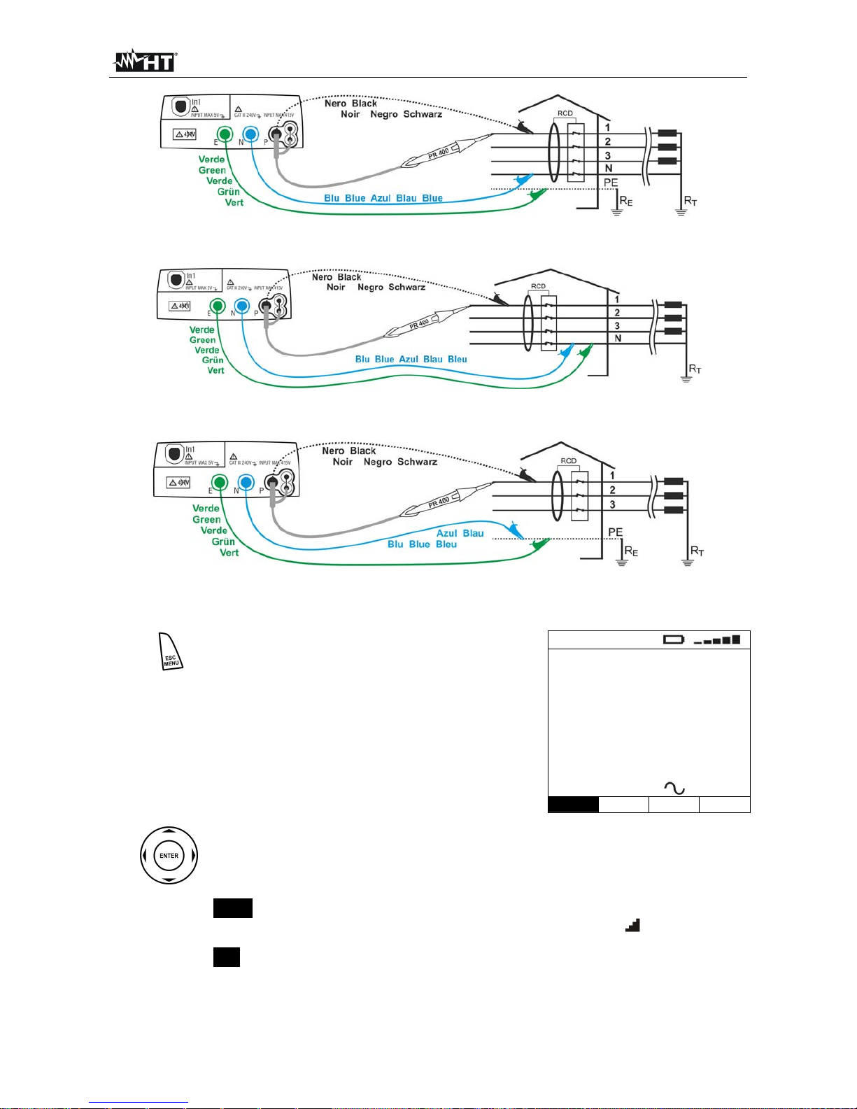
Fig. 10: Instrument connection for 230V single-phase or double-phase RCD test through
shuko cable
Fig. 11: Instrument connection for 230V single-phase or double-phase RCD test by means
of single cables and remote probe
Page 27
400 Series
EN - 26
Fig. 12: Instrument connection for 400V + N + PE three-phase RCD test by means of
single cables and remote probe
Fig. 13: Instrument connection for 400V + N (no PE) three-phase RCD test by means of
single cables and remote probe
Fig. 14: Instrument connection for 400V + PE (no N) three-phase RCD test by means of
single cables and remote probe
1.
Press the MENU key, move the cursor to RCD
in the main menu by means of the arrow keys
(,) and confirm with ENTER. Subsequently
the instrument displays a screen similar to the
one reported here to the side.
RCD
0°
---ms
FRQ=50.0Hz Ut=0.0V
VP-N=230V VP-Pe=230V
x1 30mA 50V
Func IdN RCD UL
2.
Use the , keys to select the parameter to be modified, and the , keys
to modify the parameter value.
It is not necessary to confirm the selection with ENTER.
Func
The virtual Func key allows setting the measuring mode of the
instrument, which may be: AUTO, x½, x1, x2, x5, , RA
IdN
The virtual IdN key allows setting the nominal value of the RCD’s
tripping current, which may be: 10mA, 30mA, 100mA, 300mA,
500mA, 650mA
Page 28

400 Series
EN - 27
RCD
The virtual RCD key enables the selection of the RCD type, which
may be: AC, AC S , A, A S (the options A, A S are not available if
the electrical system set is IT)
UL
The virtual UL key allows setting the limit value of contact voltage
for the system being tested, which may be: 25V, 50V
3. Should you have any doubt regarding the correct value, we suggest setting the limit
value for contact voltage to 25V, as it is the lowest limit (for safety reasons).
4. Insert the green, blue and black connectors of the three-pin shuko cable into the
corresponding input leads E, N and P of the instrument. As an alternative, use the
single cables and apply the relevant alligator clips to the free ends of the cables. It is
also possible to use the remote probe by inserting its multipolar connector into the
input lead P. Connect the shuko plug, the alligator clips or the remote probe to the
electrical mains according to Fig. 10, Fig. 11, Fig. 12, Fig. 13 and Fig. 14.
6.4.1. AUTO mode
5.
Press the GO/STOP key on the instrument or the START key on remote
probe. The instrument will start the measurement.
6. The instrument performs the following six tests referred to nominal current:
IdN x ½ with 0° phase (the RCD must not trip)
IdN x ½ with 180° phase (the RCD must not trip)
IdN x 1 with 0° phase (the RCD must trip, reset the switch)
IdN x 1 with 180° phase (the RCD must trip, reset the switch)
IdN x 5 with 0° phase (the RCD must trip, reset the switch)
IdN x 5 with 180° phase (the RCD must trip, end of test).
7. The test has a positive result if all tripping times comply with what indicated in Tab. 5.
The test has a negative result when one of the value is out of range.
CAUTION
If message “Measuring…” appears on the display, the instrument is
performing measurement. During this whole stage, do not disconnect the
test leads of the instrument from the mains.
5. The “AUTO” test is not available for 500mA and 650mA A-type RCDs.
6. While performing the test,
the instrument supplies a
leakage voltage according to
the multiplier and to the
phase indicated on the
display. From the third test
on, the RDC should trip and,
subsequently, the operator
will have to reset it
RCD
0° 180°
x1/2 >999ms >999ms
x1 28ms ---ms
x5 ---ms ---ms
FRQ=50.0Hz Ut=1.4V
VP-N=228V VP-Pe=228V
Tripping times of the RCD at the
different currents provided for in the
test
RESUME RCD
The operator is asked to resume the
RCD
AUTO 30mA 50V
Func IdN RCD UL
Page 29

400 Series
EN - 28
7. Once test is completed, in
case all six tests have had a
positive result, the
instrument displays a screen
similar to the one reported
here to the side
RCD
0° 180°
x1/2 >999ms >999ms
x1 28ms 31ms
x5 8ms 10ms
FRQ=50.0Hz Ut=1.4V
VP-N=228V VP-Pe=228V
Tripping times (expressed in ms)
RCD OK
AUTO 30mA 50V
Func IdN RCD UL
8.
The results displayed can be saved by pressing the SAVE key twice or the
SAVE key and, subsequently, the ENTER key (§ 9.1)
6.4.2. x½ mode
As an alternative:
5.
Press the GO/STOP key on the instrument or the START key on
the remote probe once. The instrument will start measuring with
a “0°” type current, injecting a current in phase with the positive
half-wave of voltage.
Or:
5.
Press the GO/STOP key on the instrument twice or the START key
on the remote probe before the hyphens disappear. The instrument
will start measuring with a “180°” type current, injecting a current in
phase with the negative half-wave of voltage.
CAUTION
If message “Measuring…” appears on the display, the instrument is
performing measurement. During this whole stage, do not disconnect the
test leads of the instrument from the mains.
6. If the RCD does not trip, the
instrument gives a double
acoustic signal which signals
the positive result of the test
and then displays a screen
similar to the one reported
here to the side
RCD
0°
> 999ms
FRQ=50.0Hz Ut=1.4V
VP-N=228V VP-Pe=228V
0° or 180° type current
Tripping time of the RCD
Detected value for contact voltage Ut
compared to the nominal value of
the set residual current
RCD OK
x1/2 30mA 50V
Func IdN RCD UL
7.
The results displayed can be saved by pressing the SAVE key twice or the
SAVE key and, subsequently, the ENTER key (§ 9.1)
Page 30

400 Series
EN - 29
6.4.3. x1, x2, x5 mode
As an alternative:
5.
Press the GO/STOP key on the instrument or the START key on
the remote probe once. The instrument will start measuring with
a “0°” type current, injecting a current in phase with the positive
half-wave of voltage.
Or:
5.
Press the GO/STOP key on the instrument twice or the START key
on the remote probe before the hyphens disappear. The instrument
will start measuring with a “180°” type current, injecting a current in
phase with the negative half-wave of voltage.
CAUTION
If message “Measuring…” appears on the display, the instrument is
performing measurement. During this whole stage, do not disconnect the
test leads of the instrument from the mains.
6. The “x5” test is not available for 500mA and 650mA A-type RCDs
7. When the RCD trips and
separates the circuit, if the
tripping time is within the
limits reported in Tab. 5, the
instrument gives a double
acoustic signal which signals
the positive result of the test
and then displays a screen
similar to the one reported
here to the side
RCD
0°
29ms
FRQ=50.0Hz Ut=1.4V
VP-N=228V VP-Pe=228V
0° or 180° type current
Tripping time of the RCD
Detected value for contact voltage Ut
compared to the nominal value of
the set residual current
RCD OK
x1 30mA 50V
Func IdN RCD UL
8.
The results displayed can be saved by pressing the SAVE key twice or the
SAVE key and, subsequently, the ENTER key (§ 9.1)
6.4.4.
mode
The standard defines the tripping times for RCDs at nominal current. The
mode is used
to detect the tripping time at tripping current (which could also be lower than the nominal
voltage).
As an alternative:
5.
Press the GO/STOP key on the instrument or the START key on
remote probe once. The instrument will start measuring with a
“0°” type current, injecting a current in phase with the positive
half-wave of voltage.
Or:
5.
Press the GO/STOP key on the instrument twice or the START key
on the remote probe before the hyphens disappear. The instrument
will start measuring with a “180°” type current, injecting a current in
phase with the negative half-wave of voltage.
Page 31

400 Series
EN - 30
CAUTION
If message “Measuring…” appears on the display, the instrument is
performing measurement. During this whole stage, do not disconnect the
test leads of the instrument from the mains.
6. According to standard EN61008, the test for selective RCDs requires an interval of 60
seconds between the tests. The mode is therefore unavailable for selective RCDs, both
of A and of AC type.
7. While performing the test,
the instrument supplies an
increasing leakage voltage
and displays a screen similar
to the one reported here to
the side
RCD
0°
18mA
> 300ms
FRQ=50.0Hz Ut=1.4V
VP-N=228V VP-Pe=228V
0° or 180° type current
Test current
the RCD under test did not trip at the
displayed test current
Measuring...
30mA 50V
Func IdN RCD UL
8. When the RCD trips and
separates the circuit, if the
tripping time and current is
within the limits reported in
Tab. 5, the instrument gives
a double acoustic signal
which signals the positive
result of the test and then
displays a screen similar to
the one reported here to the
side
RCD
0°
27mA
27ms
FRQ=50.0Hz Ut=1.4V
VP-N=228V VP-Pe=228V
0° or 180° type current
Tripping current of the RCD
Tripping time at the tripping current
of the RCD under test
RCD OK
30mA 50V
Func IdN RCD UL
9.
The results displayed can be saved by pressing the SAVE key twice or the
SAVE key and, subsequently, the ENTER key (§ 9.1)
6.4.5. RA mode
In RA mode, the contact voltage and the total earth resistance are measured by supplying
a leakage voltage equal to half the value of the set nominal current in order to prevent the
RCD from tripping.
5.
Press the GO/STOP key on the instrument or the START key on remote
probe. The instrument will start the measurement.
CAUTION
If message “Measuring…” appears on the display, the instrument is
performing measurement. During this whole stage, do not disconnect the
test leads of the instrument from the mains.
Page 32

400 Series
EN - 31
6. After the test is completed, if
the measured resistance
value matches the nominal
current and the set limit
contact voltage, RA<Ul/IdN
(1666Ω @ UL=50V and
IdN=30mA), the instrument
gives a double acoustic
signal and displays the
message “OK”, which
RCD
39
FRQ=50.0Hz Ut=1.4V
VP-N=228V VP-Pe=228V
Value of total earth resistance
Detected value for contact voltage Ut
compared to the nominal value of
the set residual current
OK
RA 30mA 50V
Func IdN RCD UL
signals that the test has been completed successfully, and displays a screen similar to
the one reported here to the side
7.
The results displayed can be saved by pressing the SAVE key twice or the
SAVE key and, subsequently, the ENTER key (§ 9.1)
6.4.6. Description of anomalous results
1. By using the RA mode, if the
instrument detects a contact
voltage higher than the set
limit, it displays the message
reported here to the side.
Check the efficiency of the
protective conductor and the
earthing
RCD
39
FRQ=50.0Hz Ut=58.4V
VP-N=228V VP-Pe=228V
Dangerous contact voltage
NOT OK
RA 30mA 50V
Func IdN RCD UL
2. If the RCD trips in a time
exceeding the limits reported
in Tab. 5, the instrument
gives a long acoustic signal
which signals the negative
result of the test and then
displays a screen similar to
the one reported here to the
side. Check that the set type
of RCD matches the type of
RCD being tested
RCD
0°
487ms
FRQ=50.0Hz Ut=1.4V
VP-N=221V VP-Pe=221V
TIME NOT OK
The tripping time is not compliant
with Tab. 5
x1 30mA 50V
Func IdN RCD UL
3. If the RCD does not trip
within the maximum duration
of the test, the instrument
gives a long acoustic signal
which signals the negative
result of the test and then
displays a screen similar to
the one reported here to the
side. Check that the set type
of RCD matches the type of
RCD being tested
RCD
0°
>999ms
FRQ=50.0Hz Ut=1.4V
VP-N=221V VP-Pe=221V
TIME NOT OK
The RCD did not trip within the
maximum duration of the test
x1 30mA 50V
Func IdN RCD UL
Page 33

400 Series
EN - 32
4. If the selective RCD trips in a
time lower than the minimum
limit reported in Tab. 5, the
instrument gives a long
acoustic signal which signals
the negative result of the test
and then displays a screen
similar to the one reported
here to the side. Check that
the set type of RCD matches
the type of RCD being tested
RCD
0°
97ms
FRQ=50.0Hz Ut=1.4V
VP-N=221V VP-Pe=221V
TIME NOT OK
The tripping time is not compliant
with Tab. 5
x1 30mA
S
50V
Func IdN RCD UL
5. If, during a test in mode,
the RCD trips in a time
exceeding the maximum
duration time provided for
the test, the instrument gives
a long acoustic signal which
signals the negative result of
the test and then displays a
screen similar to the one
reported here to the side
RCD
0°
27mA
> 300ms
FRQ=50.0Hz Ut=1.4V
VP-N=228V VP-Pe=228V
The tripping time is not conform
TIME NOT OK
30mA 50V
Func IdN RCD UL
6. If, during a test in mode,
the RCD does not trip, the
instrument gives a long
acoustic signal which signals
the negative result of the test
and then displays a screen
similar to the one reported
here to the side
RCD
0°
> 42mA
> 300ms
FRQ=50.0Hz Ut=1.4V
VP-N=228V VP-Pe=228V
The tripping time is not conform
CURRENT NOT OK
30mA 50V
Func IdN RCD UL
7.
The results displayed can be saved by pressing the SAVE key twice or the
SAVE key and, subsequently, the ENTER key (§ 9.1)
8. If the instrument detects that
the phase and neutral leads
are inverted, the message
reported here to the side is
displayed. Rotate the shuko
plug or check the connection
of the single cables
RCD
0°
---ms
FRQ=50.0Hz Ut=1.4V
VP-N=228V VP-Pe= 1V
REVERSE P-N
The phase and neutral conductors
are inverted
x1 30mA 50V
Func IdN RCD UL
Page 34

400 Series
EN - 33
9. If the instrument detects that
the phase and earth leads
are inverted, the message
reported here to the side is
displayed. Check the
connection of the cables
RCD
0°
---ms
FRQ=50.0Hz Ut=1.4V
VP-N= 1V VP-Pe=231V
REVERSE P-PE
The phase and earth conductors are
inverted
x1 30mA 50V
Func IdN RCD UL
10. If the instrument detects a
phase-to-neutral voltage and
a phase-to-earth voltage
lower than the limit, the
message reported here to
the side is displayed. Check
that the system being tested
is energized
RCD
0°
---ms
FRQ=50.0Hz Ut=1.4V
VP-N= 1V VP-Pe= 1V
Low voltage
Insufficient voltage
x1 30mA 50V
Func IdN RCD UL
11. If the instrument detects a
phase-to-neutral voltage or a
phase-to-earth voltage higher
than the limit, the message
reported here to the side is
displayed. Check that the
instrument is not phase-tophase connected
RCD
0°
---ms
FRQ=50.0Hz Ut=1.4V
VP-N=281V VP-Pe=280V
High voltage
High voltage detected
x1 30mA 50V
Func IdN RCD UL
12. If the instrument detects a
phase-to-neutral voltage
lower than the minimum limit,
it does not perform the test and
displays the message
reported here to the side.
Check the efficiency of the
neutral conductor
RCD
0°
---ms
FRQ=50.0Hz Ut=1.4V
VP-N= 1V VP-Pe=231V
MISSING N
Missing neutral conductor
x1 30mA 50V
Func IdN RCD UL
13. If the instrument detects an
extremely high earth
resistance, so that it deems
the earth conductor or the
earthing absent, it does not
perform the test and displays
the message reported here
to the side. Check the
efficiency of the protective
conductor and the earthing
RCD
0°
---ms
FRQ=50.0Hz Ut=1.4V
VP-N=231V VP-Pe=160V
MISSING-PE
Inefficient earthing
x1 30mA 50V
Func IdN RCD UL
Page 35

400 Series
EN - 34
14. If the instrument detects that, in
case the test should be
performed, a contact voltage
higher than the set limit would
build up in the system being
tested, it does not perform the
test and displays the message
reported here to the side.
Check the efficiency of the
protective conductor and the
earthing
RCD
0°
---ms
FRQ=50.0Hz Ut=0.0V
VP-N=231V VP-Pe=231V
Ut > Ulim
The instrument detects a dangerous
contact voltage
x1 30mA 50V
Func IdN RCD UL
15. If the RCD trips while
performing the preliminary
checks (automatically
performed by the instrument
before performing the
selected test), the instrument
displays the message
reported here to the side.
Check that all loads
connected downstream of the
RCD
0°
---ms
FRQ=50.0Hz Ut=0.0V
VP-N=231V VP-Pe=231V
RCD TRIPPED
RCD tripped during preliminary
checks
x1 30mA 50V
Func IdN RCD UL
RCD being tested are disconnected and that the set value for IdN matches the RCD
being tested
16. If, after repeated tests, the
instrument has overheated,
the message reported here
to the side is displayed. Wait
for this message to
disappear before performing
other tests
RCD
0°
---ms
FRQ=50.0Hz Ut=1.4V
VP-N=231V VP-Pe=231V
Hot temperature
Overheated instrument
x1 30mA 50V
Func IdN RCD UL
17.
The previous anomalous results cannot be saved
Page 36

400 Series
EN - 35
6.5. LOOP: MEASUREMENT OF LINE/LOOP IMPEDANCE
This function is performed according to standard IEC/EN61557-3 and allows measuring
the line impedance, the earth fault loop impedance and the prospective short circuit
current. The following operating modes are available:
P-N the instrument measures impedance between the phase conductor and the
neutral conductor and calculates the prospective phase-to-neutral short circuit
current
P-P the instrument measures impedance between two phase conductors and
calculates the prospective phase-to-phase short circuit current
P-PE the instrument measures the fault loop impedance and calculates the
prospective fault current
CAUTION
The measurement of line impedance or fault loop impedance involves the
circulation of a maximum current according to the technical specifications of
the instrument (§ 12.1). This could cause the tripping of possible
magnetothermal or differential protections at lower tripping currents.
Fig. 15: Instrument connection for 230V single-phase or double-phase P-N line impedance
and P-PE fault loop impedance measurement through shuko cable
Fig. 16: Instrument connection for 230V single-phase or double-phase P-N line impedance
and P-PE fault loop impedance measurement through single cables and remote probe
Fig. 17: Instrument connection for 400V + N + PE three-phase P-N line impedance and
P-PE fault loop impedance measurement through single cables and remote probe
Page 37

400 Series
EN - 36
Fig. 18: Instrument connection for 400V + N + PE three-phase P-P line impedance
measurement by means of single cables and remote probe
Fig. 19: Instrument connection for 400V + PE (no N) three-phase P-PE fault loop
impedance measurement through single cables and remote probe
1.
Press the MENU key, move the cursor to
LOOP in the main menu by means of the
arrow keys (,) and confirm with ENTER.
Subsequently the instrument displays a screen
similar to the one reported here to the side.
LOOP
0°
----
----A
FRQ=50.0Hz
VP-N=228V VP-Pe=228V
P-PE STD
Func Mod.
2.
Use the , keys to select the parameter to be modified, and the , keys
to modify the parameter value.
It is not necessary to confirm the selection with ENTER.
Func
The virtual Func key allows setting the measuring mode of the
instrument, which may be: P-N, P-P, P-PE
UL
The virtual UL key, active only when an IT electrical system and the
P-PE mode have been set (§ 5.2.5), allows setting the limit value of
contact voltage for the system being tested, which may be: 50V,
25V
Mod.
The virtual UL key, not active when an IT electrical system and the
P-PE mode have been set (§ 5.2.5), allows setting the instrument’s
operating mode, which can be: STD, Z2
ICAL
The virtual ICAL key, active only when the Z2Ω mode has been
selected with the MOD key, allows selecting the assumed shortcircuit or fault current displayed. Following values are available:
IkMax3Ph, IkMin3Ph, IkMax2Ph, IkMin2Ph, IkMaxP-N, IkMinPN, IkMaxP-PE, IkMinP-PE, IkSTD
Page 38

400 Series
EN - 37
RMT
The virtual RMT key, active only when the Z2Ω mode has been
selected with the MOD key, displays the serial number and the FW
version of the remote unit IMP57
3. If possible, disconnect all loads connected downstream of the measured point, as the
impedance of these users could distort the test results.
4. Use the virtual Mod. key to set the STD test mode.
Should you perform high-resolution tests, recommended
near MT/BT transformers, we suggest using the Z2
mode, which implies the use of the optional accessory
IMP57. Upon the selection of the Z2 mode, the
instrument displays a screen similar to the one reported
here to the side. Connect accessory IMP57 to the
instrument by means of the serial optical cable and
perform the measurements as described in the relevant
user manual.
LOOP
----
----A
FRQ=50.0Hz
VP-N=228V VP-Pe=228V
P-N
Z2
Func Mod.
5. Insert the green, blue and black connectors of the three-pin shuko cable into the
corresponding input leads E, N and P of the instrument. As an alternative, use the
single cables and apply the relevant alligator clips to the free ends of the cables. It is
also possible to use the remote probe by inserting its multipolar connector into the
input lead P. Connect the shuko plug, the alligator clips or the remote probe to the
electrical mains according to Fig. 15, Fig. 16, Fig. 17, Fig. 18 and Fig. 19.
6.5.1. P-N mode
6.
Press the GO/STOP key on the instrument or the START key on remote
probe. The instrument will start the measurement.
CAUTION
If message “Measuring…” appears on the display, the instrument is
performing measurement. During this whole stage, do not disconnect the
test leads of the instrument from the mains.
7. Once test is completed, if the
measured impedance value
is lower than the full scale,
the instrument gives a
double acoustic signal and
then displays a screen
similar to the one reported
here to the side
LOOP
1.07
215A
FRQ=50.0Hz
VP-N=228V VP-Pe=228V
Measured impedance value
Prospective short circuit current
P-N and P-PE measured voltages
P-N STD
Func Mod.
Page 39

400 Series
EN - 38
Formula used for calculating the prospective short circuit current:
PN
N
CC
Z
U
I
where: ZPN is the measured phase-to-neutral impedance
U
N
is the nominal phase-to-neutral voltage
U
N
= 127V if V
P-N meas
≤ 150V
U
N
= 230V or UN = 240V (§ 5.2.3) if V
P-N meas
> 150V
8.
9.
The results displayed can be saved by pressing the SAVE key twice or the
SAVE key and, subsequently, the ENTER key (§ 9.1)
6.5.2. P-P mode
6.
Press the GO/STOP key on the instrument or the START key on remote
probe. The instrument will start the measurement.
CAUTION
If message “Measuring…” appears on the display, the instrument is
performing measurement. During this whole stage, do not disconnect the
test leads of the instrument from the mains.
7. Once test is completed, if the
measured impedance value
is lower than the full scale,
the instrument gives a
double acoustic signal and
then displays a screen
similar to the one reported
here to the side
LOOP
0.57
701A
FRQ=50.0Hz
VP-P=402V VP-Pe=230V
Measured impedance value
Prospective short circuit current
P-P and P-PE measured voltages
P-P STD
Func Mod.
Formula used for calculating the prospective short circuit current:
PP
N
CC
Z
U
I
where: ZPP is the measured phase-to-phase impedance
U
N
is the nominal phase-to-phase voltage
U
N
= 127V if V
P-P meas
≤ 150V
U
N
= 230V or UN = 240V (§ 5.2.3) if 150V < V
P-P meas
≤ 265V
U
N
= 400V or UN = 415V (§ 5.2.3) if V
P-P meas
> 265V
8.
9.
The results displayed can be saved by pressing the SAVE key twice or the
SAVE key and, subsequently, the ENTER key (§ 9.1)
Page 40

400 Series
EN - 39
6.5.3. P-PE mode in TT or TN systems
As an alternative:
6.
Press the GO/STOP key on the instrument or the START key on
remote probe once. The instrument will start measuring with a
“0°” type current, injecting a current in phase with the positive
half-wave of voltage
Or:
6.
Press the GO/STOP key on the instrument twice or the START key
on the remote probe before the hyphens disappear. The instrument
will start measuring with a “180°” type current, injecting a current in
phase with the negative half-wave of voltage
CAUTION
If message “Measuring…” appears on the display, the instrument is
performing measurement. During this whole stage, do not disconnect the
test leads of the instrument from the mains.
7. Once test is completed, if the
measured impedance value
is lower than the full scale,
the instrument gives a
double acoustic signal and
then displays a screen
similar to the one reported
here to the side
LOOP
0°
1.07
215A
FRQ=50.0Hz
VP-N=230V VP-Pe=230V
0° or 180° type current
Measured impedance value
Prospective short circuit current
P-P and P-PE measured voltages
P-PE STD
Func Mod.
Formula used for calculating the prospective fault current:
PE
N
CC
Z
U
I
where: ZPE is the measured fault impedance
U
N
is the nominal phase-to-earth voltage
U
N
= 127V if V
P-PE meas
≤ 150V
U
N
= 230V or UN = 240V (§ 5.2.3) if V
P-PE meas
> 150V
8.
9. In TT systems, the impedance value measured by the instrument may only be referred
to the value of the total earth resistance. Therefore, in compliance with the
prescriptions of standard CEI64-8, the measured value may be taken as the value for
the system’s earth resistance
10.
The results displayed can be saved by pressing the SAVE key twice or the
SAVE key and, subsequently, the ENTER key (§ 9.1)
Page 41

400 Series
EN - 40
6.5.4. P-PE mode in IT systems
6.
Press the GO/STOP key on the instrument or the START key on remote
probe. The instrument will start the measurement.
CAUTION
If message “Measuring…” appears on the display, the instrument is
performing measurement. During this whole stage, do not disconnect the
test leads of the instrument from the mains.
7. Once test is completed, if the
measured contact voltage
value is lower than the set
limit, the instrument gives a
double acoustic signal and
then displays a screen
similar to the one reported
here to the side
LOOP
63mA
Ut=19.7V
FRQ=50.0Hz
VP-N=230V VP-Pe=230V
First earth fault current
Measured contact voltage value
P-N and P-PE measured voltages
P-PE 25V IT
Func UL
8.
The results displayed can be saved by pressing the SAVE key twice or the
SAVE key and, subsequently, the ENTER key (§ 9.1)
6.5.5. Description of anomalous results
1. If the instrument detects an
impedance higher than the
full scale, at the and of the
test it displays the screen
reported here to the side and
gives a long acoustic signal
LOOP
>199.9
---A
FRQ=50.0Hz
VP-P=402V VP-Pe=230V
Impedance value higher than the full
scale
P-P and P-PE measured voltage
P-P STD
Func Mod.
2.
The results displayed can be saved by pressing the SAVE key twice or the
SAVE key and, subsequently, the ENTER key (§ 9.1)
3. If the instrument detects that
the phase and neutral leads
are inverted, the message
reported here to the side is
displayed. Rotate the shuko
plug or check the connection
of the single cables
LOOP
----
---A
FRQ=50.0Hz
VP-N=228V VP-Pe= 1V
REVERSE P-N
The phase and neutral conductors
are inverted
P-N STD
Func Mod.
Page 42

400 Series
EN - 41
4. If the instrument detects that
the phase and earth leads
are inverted, the message
reported here to the side is
displayed. Check the
connection of the cables
LOOP
----
---A
FRQ=50.0Hz
VP-N= 1V VP-Pe=231V
REVERSE P-PE
The phase and earth conductors are
inverted
P-N STD
Func Mod.
5. If the instrument detects a
phase-to-neutral voltage and
a phase-to-earth voltage
lower than the limit, the
message reported here to
the side is displayed. Check
that the system being tested
is energized
LOOP
----
---A
FRQ=50.0Hz
VP-N= 1V VP-Pe= 1V
Low voltage
Insufficient voltage
P-N STD
Func Mod.
6. If the instrument detects a
phase-to-neutral voltage or a
phase-to-earth voltage higher
than the limit, the message
reported here to the side is
displayed. Check that the
instrument is not phase-tophase connected
LOOP
----
---A
FRQ=50.0Hz
VP-N=281V VP-Pe=280V
High voltage
High voltage detected
P-N STD
Func Mod.
7. If the instrument detects a
phase-to-neutral voltage
lower than the minimum limit,
it does not perform the test and
displays the message
reported here to the side.
Check the efficiency of the
neutral conductor
LOOP
----
---A
FRQ=50.0Hz
VP-N= 1V VP-Pe=231V
MISSING N
Missing neutral conductor
P-N STD
Func Mod.
8. If the instrument detects an
extremely high earth
resistance, so that it deems
the earth conductor or the
earthing absent, it does not
perform the test and displays
the message reported here
to the side. Check the
efficiency of the protective
conductor and the earthing
LOOP
----
---A
FRQ=50.0Hz
VP-N=231V VP-Pe=160V
MISSING-PE
Inefficient earthing
P-N STD
Func Mod.
Page 43

400 Series
EN - 42
9. By using the P-PE mode, if
the instrument detects that,
in case the test should be
performed, a contact voltage
higher than the set limit
would build up in the system
being tested, it does not
perform the test and displays
the message reported here
to the side. Check the
LOOP
0°
----
---A
FRQ=50.0Hz
VP-N=231V VP-Pe=231V
Ut > Ulim
Dangerous contact voltage
P-PE STD
Func Mod.
efficiency of the protective conductor and the earthing
10. If, after repeated tests, the
instrument has overheated,
the message reported here
to the side is displayed. Wait
for this message to
disappear before performing
other tests
LOOP
----
---A
FRQ=50.0Hz
VP-N=231V VP-Pe=231V
Hot temperature
Overheated instrument
P-N STD
Func Mod.
11.
The previous anomalous results cannot be saved
Page 44

400 Series
EN - 43
6.6. RA 15MA: MEASUREMENT OF THE TOTAL EARTH RESISTANCE THROUGH
THE SOCKET-OUTLET
This function is performed in compliance with standards IEC/EN61557-6 and allows
measuring the impedance of the fault loop, comparable to the overall earth resistance in
TT systems. One single operating mode is available.
CAUTION
The measurement of the overall earth resistance involves the circulation of a
current between phase and earth according to the technical specifications of
the instrument (§ 12.1). This could cause the tripping of possible protections
at lower tripping currents.
Fig. 20: Instrument connection for 230V single-phase or double-phase P-PE fault loop
impedance measurement through shuko cable
Fig. 21: Instrument connection for 230V single-phase or double-phase P-PE fault loop
impedance measurement through single cables and remote probe
Fig. 22: Instrument connection for 400V + N + PE three-phase P-PE fault loop impedance
measurement through single cables and remote probe
Fig. 23: Instrument connection for 400V + PE (no N) three-phase P-PE fault loop
impedance measurement through single cables and remote probe
Page 45

400 Series
EN - 44
1.
Press the MENU key, move the cursor to Ra in
the main menu by means of the arrow keys
(,) and confirm with ENTER. Subsequently
the instrument displays a screen similar to the
one reported here to the side.
Ra
-----
----A
FRQ=50.0Hz
VP-N=228V VP-Pe=228V
50V
UL
2.
Use the arrow keys , to set the limit value of contact voltage for the
system being tested, which may be: 50V, 25V.
It is not necessary to confirm the selection with ENTER.
3. If possible, disconnect all loads connected downstream of the measured point, as the
impedance of these users could distort the test results.
4. Insert the green, blue and black connectors of the three-pin shuko cable into the
corresponding input leads E, N and P of the instrument. As an alternative, use the
single cables and apply the relevant alligator clips to the free ends of the cables. It is
also possible to use the remote probe by inserting its multipolar connector into the
input lead P. Connect the shuko plug, the alligator clips or the remote probe to the
electrical mains according to Fig. 20, Fig. 21, Fig. 22 and Fig. 23.
5.
Press the GO/STOP key on the instrument or the START key on remote
probe. The instrument will start the measurement.
CAUTION
If message “Measuring…” appears on the display, the instrument is
performing measurement. During this whole stage, do not disconnect the
test leads of the instrument from the mains.
6. Once test is completed, if the
measured impedance value
is lower than the full scale,
the instrument gives a
double acoustic signal and
then displays a screen
similar to the one reported
here to the side
Ra
1.07
215A
FRQ=50.0Hz
VP-N=228V VP-Pe=228V
Measured impedance value
Prospective fault current
P-N and P-PE measured voltages
50V
UL
Page 46

400 Series
EN - 45
Formula used for calculating the prospective fault current:
PE
N
CC
Z
U
I
where: ZPE is the measured fault impedance
U
N
is the nominal phase-to-earth voltage
U
N
= 127V if V
P-PE meas
≤ 150V
U
N
= 230V or UN = 240V (§ 5.2.3) if V
P-PE meas
> 150V
7.
8. In TT systems, the impedance value measured by the instrument may only be referred
to the value of the total earth resistance. Therefore, in compliance with the
prescriptions of standard CEI64-8, the measured value may be taken as the value for
the system’s earth resistance
9.
The results displayed can be saved by pressing the SAVE key twice or the
SAVE key and, subsequently, the ENTER key (§ 9.1)
6.6.1. Description of anomalous results
1. If the instrument detects an
impedance higher than the
full scale, at the and of the
test it displays the screen
reported here to the side and
gives a long acoustic signal
Ra
>1999
---A
FRQ=50.0Hz
VP-N=230V VP-Pe=230V
Impedance value higher than the full
scale
P-P and P-PE measured voltages
NOT OK
50V
UL
2. If the instrument detects an
impedance higher than the
limit value calculated as
U
LIM
/30mA (1666Ω@
U
LIM
=50V, 833Ω@U
LIM
=25V,
it displays the screen
reported here to the side and
gives a long acoustic signal
Ra
1789
0.1A
FRQ=50.0Hz
VP-N=228V VP-Pe=228V
NOT OK
impedance value is higher than the
limit value calculated as U
LIM
/30mA
50V
UL
3.
The results displayed can be saved by pressing the SAVE key twice or the
SAVE key and, subsequently, the ENTER key (§ 9.1)
4. If the instrument detects that
the phase and neutral leads
are inverted, the message
reported here to the side is
displayed. Rotate the shuko
plug or check the connection
of the single cables
Ra
----
---A
FRQ=50.0Hz
VP-N=228V VP-Pe= 1V
REVERSE P-N
The phase and neutral conductors
are inverted
50V
UL
Page 47

400 Series
EN - 46
5. If the instrument detects that
the phase and earth leads
are inverted, the message
reported here to the side is
displayed. Check the
connection of the cables
Ra
----
---A
FRQ=50.0Hz
VP-N= 1V VP-Pe=231V
REVERSE P-PE
The phase and earth conductors are
inverted
50V
UL
6. If the instrument detects a
phase-to-neutral voltage and
a phase-to-earth voltage
lower than the limit, the
message reported here to
the side is displayed. Check
that the system being tested
is energized
Ra
----
---A
FRQ=50.0Hz
VP-N= 1V VP-Pe= 1V
Low voltage
Insufficient voltage
50V
UL
7. If the instrument detects a
phase-to-neutral voltage or a
phase-to-earth voltage higher
than the limit, the message
reported here to the side is
displayed. Check that the
instrument is not phase-tophase connected
Ra
----
---A
FRQ=50.0Hz
VP-N=281V VP-Pe=280V
High voltage
High voltage detected
50V
UL
8. If the instrument detects a
phase-to-neutral voltage
lower than the minimum limit,
it does not perform the test and
displays the message
reported here to the side.
Check the efficiency of the
neutral conductor
Ra
----
---A
FRQ=50.0Hz
VP-N= 1V VP-Pe=231V
MISSING N
Missing neutral conductor
50V
UL
Page 48

400 Series
EN - 47
9. If the instrument detects an
extremely high earth
resistance, so that it deems
the earth conductor or the
earthing absent, it does not
perform the test and displays
the message reported here
to the side. Check the
efficiency of the protective
conductor and the earthing
Ra
----
---A
FRQ=50.0Hz
VP-N=231V VP-Pe=160V
MISSING-PE
Inefficient earthing
50V
UL
10. If the instrument detects that,
in case the test should be
performed, a contact voltage
higher than the set limit
would build up in the system
being tested, it does not
perform the test and displays
the message reported here
to the side. Check the
efficiency of the
Ra
0°
----
---A
FRQ=50.0Hz
VP-N=231V VP-Pe=231V
Ut > Ulim
Dangerous contact voltage
50V
UL
protective conductor and the earthing
11. If, after repeated tests, the
instrument has overheated,
the message reported here
to the side is displayed. Wait
for this message to
disappear before performing
other tests
Ra
----
---A
FRQ=50.0Hz
VP-N=231V VP-Pe=231V
Hot temperature
Overheated instrument
50V
UL
12.
The previous anomalous results cannot be saved
Page 49

400 Series
EN - 48
6.7. 123: PHASE SEQUENCE TEST
This function is performed in compliance with standards IEC/EN61557-7 and allows testing
the phase sequence by direct contact with parts under voltage (no cables with insulating
sheath). The following operating modes are available:
1T one test lead mode
2T two test leads mode.
Fig. 24: Instrument connection for measuring the phase sequence with one lead, phase 1 connection
Fig. 25: Instrument connection for measuring the phase sequence with two leads, phase 1 connection
1.
Press the MENU key, move the cursor to 123
in the main menu by means of the arrow keys
(,) and confirm with ENTER. Subsequently
the instrument displays a screen similar to the
one reported here to the side.
123
---
1T
Func
2.
Use the arrow keys , to set the measuring mode of the instrument,
which may be: 1T, 2T.
It is not necessary to confirm the selection with ENTER.
3. Insert the blue and black connectors of the single cables into the corresponding input
leads N and P of the instrument. Apply the relevant alligator clips to the free ends of
the cables. It is also possible to use the remote probe by inserting its multipolar
connector into the input lead P. Connect the alligator clips, the probes or the remote
probe to the electrical mains according to Fig. 24 and Fig. 25.
4.
Press the GO/STOP key on the instrument or the START key on remote
probe. The instrument will start the measurement.
Page 50

400 Series
EN - 49
CAUTION
If message “Measuring…” appears on the display, the instrument is
performing measurement. During this whole stage, do not disconnect the
test leads of the instrument from the mains.
5. The instrument switches to
stand-by mode and displays
the screen reported here to
the side until the test lead
detects a voltage higher than
the minimum limit value
123
---
Waiting phase 1
Waiting for phase 1
1T
Func
6. When the instrument detects
a voltage higher than the
minimum limit value on the
test lead, the instrument
displays the screen reported
here to the side and starts
measuring the first voltage.
The instrument gives a long
acoustic signal until input
voltage is present
123
---
Measuring…
Measuring phase 1
1T
Func
7. Once acquisition is
completed, the instrument
switches to stand-by mode
and displays the screen
reported here to the side until
the test lead detects again a
voltage higher than the
minimum limit value
123
1--
Waiting phase 2
Waiting for phase 2
1T
Func
8. Move the black test lead to the second voltage of the sequence tested as in Fig. 26
and Fig. 27.
Fig. 26: Instrument connection for measuring the phase sequence with one lead, phase 2 connection
Page 51

400 Series
EN - 50
Fig. 27: Instrument connection for measuring the phase sequence with two leads, phase 2 connection
9. When the instrument detects
a voltage higher than the
minimum limit value on the
test lead, the instrument
displays the screen reported
here to the side and starts
measuring the second
voltage. The instrument
gives a long acoustic signal
until input voltage is present
123
1--
Measuring…
Measuring phase 2
1T
Func
10. Once acquisition is
completed, if the instrument
has detected a correct phase
sequence, it displays 123
and the message OK. It also
gives a double acoustic
signal
123
123
Correct phase sequence
OK
1T
Func
11. Once acquisition is
completed, if the instrument
has detected two voltages in
phase, it displays a screen
similar to the one reported
here to the side and gives a
double acoustic signal
123
11-
Phase conformity
OK
1T
Func
12.
The results displayed can be saved by pressing the SAVE key twice or the
SAVE key and, subsequently, the ENTER key (§ 9.1)
Page 52

400 Series
EN - 51
6.7.1. Description of anomalous results
1. Once acquisition is
completed, if the instrument
has detected an uncorrect
phase sequence, it displays
a screen similar to the one
reported here to the side and
gives a long acoustic signal
123
132
Correct phase sequence
NOT OK
1T
Func
2.
The results displayed can be saved by pressing the SAVE key twice or the
SAVE key and, subsequently, the ENTER key (§ 9.1)
3. If between the acquisition of
the first and second voltage
a time higher than the limit
time has elapsed, the
instrument displays a screen
similar to the one reported
here to the side and gives a
long acoustic signal
123
1--
Time out
1T
Func
4. If, during voltage acquisition,
the instrument detects an
input voltage higher than the
maximum limit value, it
displays a screen similar to
the one reported here to the
side and stops measuring
123
---
Vin > Vmax
2T
Func
5.
The previous anomalous results cannot be saved
Page 53

400 Series
EN - 52
7. AUXILIARY MEASUREMENTS
7.1. AUX: REAL TIME MEASUREMENT OF THE ENVIRONMENTAL
PARAMETERS
By means of external transducers, this function allows measuring the following
environmental parameters:
AIR air speed by means of air-speed transducer
RH air humidity by means of humidity transducer
TMP °F air temperature in °F by means of thermometric transducer
TMP °C air temperature in °C by means of thermometric transducer
dB acoustic pressure by means of sound level transducer
Lux lighting by means of luxmetric transducer
VOLT input voltage (without applying any transduction constant)
Fig. 28: Connection between an
environmental probe and the instrument
Fig. 29: Connection between the sound level
probe and the instrument
1.
Press the MENU key, move the cursor to AUX
in the main menu by means of the arrow keys
(,) and confirm with ENTER. Subsequently
the instrument displays a screen similar to the
one reported here to the side. Except in dB
mode, the instrument measures and shows on
the display the instant value of the input
parameter in real time, and RUN appears in
the right bottom part of the display
AUX
In1 = 7.08 Lux
Lux LX 20
RUN
Func FS
2.
Use the , keys to select the parameter to be modified, and the , keys
to modify the parameter value.
It is not necessary to confirm the selection with ENTER.
Func
The virtual Func key allows setting the the type of environmental
measurement to perform, which may be: AIR, RH, TMP °F, TMP
°C, dB, Lux, VOLT
FS
The virtual FS key, active only when the Lux mode has been
selected with the Func key, allows selecting the clamp full scale
among the values: 20, 2k, 20k
Page 54

400 Series
EN - 53
7.1.1. dB mode
3. Connect the sound level probe to the instrument’s optical input by means of the optical cable
4.
Press the GO/STOP key. The instrument starts
measuring the acoustic pressure. The following
values are displayed:
SPL acoustic pressure
Peak acoustic pressure peak
Duration time elapsed since the
beginning of the recording
AUX
SPL ---- dB
Peak ---- dB
Duration 0000:00:00
dB
Func
5.
Press the GO/STOP key again. The instrument
stops measuring and displays the following
values:
Leq equivalent level of acoustic
pressure
Peak acoustic pressure peak
Duration duration of the recording
AUX
Leq ---- dB
Peak ---- dB
Duration 0000:00:00
dB
Func
The equivalent level of the acoustic pressure is defined as:
2
0
0
2
10
1
log10
P
dtP
T
Leq
T
i
where: P0 is the reference pressure, ca. 2105 Pa
P
i
is the instant pressure of the acoustic range
In praxis, the following formula is used:
N
N
Leq
N
i
L
i
i
1
10
10
10
log10
where: L
i
is the sampled level [dB]
N
i
is the number of samples measured for the Li level
N is the number of samples measured
6.
7. Please note that Lep, the personal exposure level, is defined as the equivalent level of
the acoustic range a person is exposed to during a normal workshift (8 hours). "Lep"
coincides therefore with "Leq" calculated for 8 hours.
8.
Once recording is completed, measures can be saved by pressing the SAVE
key twice or the SAVE key and, subsequently, the ENTER key (§ 9.1)
Page 55

400 Series
EN - 54
7.1.2. AIR, RH, TMP °F, TMP °C, Lux mode
3. Insert the connector of the probe being used into the instrument input In1 making sure
that the probe connected and the set measurement unit correspond
4.
Press the GO/STOP key. The instrument stops
updating the measured value and STOP
appears on the right bottom part of the display.
Press the same key again to restart the
measurement and the real-time display of the
instant value of the input parameter. In this
case, RUN appears on the right bottom part of
the display.
AUX
In1 = 7.08 Lux
Lux LX 20
STOP
Func FS
5.
Measures can be saved, both in RUN and in STOP mode, by pressing the
SAVE key twice or the SAVE key and, subsequently, the ENTER key (§ 9.1)
7.1.3. Description of anomalous results
1. In AIR, RH, TMP °F, TMP
°C, Lux or VOLT mode, if the
instrument measures an
input value higher than the
full scale, it displays a screen
similar to the one reported
here to the side. Check that
the full scale selected on the
instrument matches the full
scale on the transducer
AUX
In1 > 20.00 kLux
Measured value higher than the
instrument’s full scale
Lux Lx 20k
Func FS
2.
The results displayed can be saved by pressing the SAVE key twice or the
SAVE key and, subsequently, the ENTER key (§ 9.1)
3. “DB” sound mode only: when
starting recording without the
sound level probe being
connected to the instrument,
a screen similar to the one
on the side will be shown
AUX
SPL ---- dB
Peak ---- dB
Durata 0000:00:00
NO HT55
The instrument does not find the
sound level transducer HT55
dB
Func
4.
The previous anomalous result cannot be saved
Page 56

400 Series
EN - 55
7.2. LEAK: REAL TIME MEASUREMENT OF THE LEAKAGE CURRENT
THROUGH AN EXTERNAL CLAMP
Using an external clamp, this function allows measuring the leakage current.
Fig. 30: Indirect measurement of leakage current in three-phase systems
Fig. 31: Direct measurement of leakage current in three-phase systems
1.
Press the MENU key, move the cursor to
LEAK in the main menu by means of the arrow
keys (,) and confirm with ENTER.
Subsequently the instrument measures in real
time and displays, in a screen similar to the
one reported here to the side, the instant value
of the input parameter, and RUN appears on
the right bottom part of the display
LEAK
I = 00.0 A
Imax = 00.0 A
100A
RUN
FS
2.
Use the arrow keys , to select the clamp full scale among the values:
1A, 10A, 30A, 100A, 200A, 300A, 400A, 1000A, 2000A, 3000A. the
changes made to the FS value will also be applied to the PWR function (§
8.1). It is not necessary to confirm the selection with ENTER.
3. The FS set on the instrument has always to match the one on the clamp being used.
For the leakage current, the instrument and the clamp are generally set to FS=1A
4. Insert the clamp connector into the instrument input In1
5. For indirect measurements of the leakage current, connect the external clamp
according to Fig. 30. For direct measurements of the leakage current, connect the
external clamp according to Fig. 31 and disconnect possible additional earth
connections which could influence the test results
Page 57

400 Series
EN - 56
CAUTION
Possible additional earth connections could influence the measured value.
For the difficulty of this measurement and the sometimes real difficulty in
removing the clamps, we recommend performing the measurement
indirectly.
6.
Press the GO/STOP key. The instrument stops
updating the measured value and STOP
appears on the right bottom part of the display.
Press the same key again to restart the
measurement and the real-time display of the
instant value of the input parameter. In this
case, RUN appears on the right bottom part of
the display
LEAK
I = 47.0 A
Imax = 86.4 A
100A
STOP
FS
7.
The results displayed can be saved, both in RUN and in STOP mode, by
pressing the SAVE key twice or the SAVE key and, subsequently, the
ENTER key (§ 9.1)
7.2.1. Description of anomalous results
1. If the instrument detects that
the current is higher than the
one of the set full scale, the
screen on the side will be
displayed. Check that the full
scale selected on the
instrument matches the full
scale on the transducer
LEAK
I > 100.0 A
Imax > 100.0 A
Measured value higher than the
instrument’s full scale
100A
RUN
FS
2.
The results displayed can be saved by pressing the SAVE key twice or the
SAVE key and, subsequently, the ENTER key (§ 9.1)
Page 58

400 Series
EN - 57
8. MAINS ANALYSIS
8.1. PWR: REAL TIME MEASUREMENT OF THE MAINS PARAMETERS
This function allows measuring the voltage of the electrical mains and of the relevant
harmonics. Using an external clamp, it is also possible to measure the current and the
relevant harmonics as well as other electrical parameters such as power, power factor, etc.
The following operating modes are available:
PAR measurement of electrical parameters such as current, voltage, power, power
factor, etc.
HRM V measurement of voltage harmonics
HRM I measurement of current harmonics
Fig. 32: Instrument connection for single-phase, double-phase or three-phase measurements
1.
Press the MENU key, move the cursor to PWR
in the main menu by means of the arrow keys
(,) and confirm with ENTER. The
instrument measures in real time and displays,
in a screen similar to the one reported here to
the side, the instant value of the input
parameters, and RUN appears on the right
bottom part of the display
PWR
V = 230.8 V
I = 27.2 A
f = 50.0 Hz
P = 5.09 kW
S = 6.28 kVA
Q = 2.14 kVAR
pf = 0.94 i
dpf = 0.94 i
PAR 100A 4005
RUN
Func FS TYPE
2.
Use the , keys to select the parameter to be modified, and the , keys
to modify the parameter value.
It is not necessary to confirm the selection with ENTER.
Func
The virtual Func key allows setting the measuring mode of the
instrument, which may be: PAR, HRM V, HRM I
FS
The virtual FS key, active only when the PAR mode has been
selected with the Func key, allows selecting the clamp full scale
among the values: 1A, 10A, 30A, 100A, 200A, 300A, 400A,
1000A, 2000A, 3000A. The changes made to the FS value will also
be applied to the LEAK function (§ 7.2). If the FS 100A has been
set, it's possible to select the clamp model: Type = "4005"
(HT4005) or "STD" (Standard clamp).
PAG
The virtual FS key, active only when the HRM V or the HRM I
mode has been selected with the Func key, allows scrolling down
the bar graph of the harmonics window by window. Following
options are available: h02÷h08, h09÷h15, h16÷h22, h23÷h29,
h30÷h36, h37÷h43, h44÷h50
Page 59

400 Series
EN - 58
hxx
The virtual FS key, active only when the HRM V or the HRM I
mode has been selected with the Func key, allows increasing or
decreasing the ordinal harmonic number whose value is displayed
3. Insert the clamp connector into the instrument input In1
4.
Staple the phase to be tested. Insert both the black and blue connectors of the single
cables into the relative P and N instrument input leads. Insert the relative alligator clips
into the free end of the cables and connect the test leads to the test ends of the
conductor to be tested as in Fig. 32. The arrow on the clamp must point in the direction
of the power flow, i.e. from generator to load
8.1.1. PAR mode
5.
Press the GO/STOP key. The instrument stops
updating the measured values and STOP
appears on the right bottom part of the display.
Press the same key again to restart the
measurement and the real-time display of the
instant values of the input parameters. In this
case, RUN appears on the right bottom part of
the display
PWR
V = 230.8 V
I = 27.2 A
f = 50.0 Hz
P = 5.09 kW
Q = 2.14 kVAR
S = 6.28 kVA
pf = 0.94 i
dpf = 0.94 i
PAR 100A 4005
STOP
Func FS TYPE
6.
The results displayed can be saved, both in RUN and in STOP mode, by
pressing the SAVE key twice or the SAVE key and, subsequently, the
ENTER key (§ 9.1)
8.1.2. HRM V ane HRM I mode
8.
Press the GO/STOP key. The instrument stops
updating the measured value and STOP
appears on the right bottom part of the display.
Press the same key again to restart the
measurement and the real-time display of the
instant value of the input parameter. In this
case, RUN appears on the right bottom part of
the display
PWR
h02 = 10.0 %
thdV = 11.5 %
HRM V
STOP
Func PAG hxx
7.
The results displayed can be saved, both in RUN and in STOP mode, by
pressing the SAVE key twice or the SAVE key and, subsequently, the
ENTER key (§ 9.1)
Page 60

400 Series
EN - 59
9. MEMORY
9.1. HOW TO SAVE A MEASURE
1. When the SAVE key is first
pressed, as described in the
§s regarding the different
measurements, the
instrument displays a screen
similar to the one on the side
SAVE
Memory: 015
Position: 010
Location: 194
First available memory location (last
saved + 1)
Last P parameter set value
Last L parameter set value
P L
2. the P (place) and L (location) parameters can be used to facilitate the operator’s task
in determining the point in which the measurement was carried out. These parameters
values can be modified from 001 to 255, and is not bound to the memory location in
which the results will be saved and which keeps increasing
3. It is not possible to set the memory location in which the measure is saved. The
instrument always uses the first location available, i.e. the next location available after
the last used one
4.
Use the , keys to select the parameter to be modified, and the , keys
to modify the parameter value.
As an alternative:
5. or
Press the ENTER or SAVE key to save the
measure. The instrument gives a double acoustic
signal to confirm the saving
Or:
5.
Press the ESC key to exit without saving
9.1.1. Description of anomalous results
1. Should you effect a saving
procedure when all 500
memory cells are full, the
instrument displays a screen
similar to the one reported
here to the side
LEAK
I = 47.0 A
Imax = 86.4 A
FULL MEMORY
The whole instrument memory has
already been used
100A
RUN
FS
Page 61

400 Series
EN - 60
9.2. SAVED DATA MANAGEMENT
1.
Press the MENU key, move the cursor to MEM
in the main menu by means of the arrow keys
(,) and confirm with ENTER. Subsequently
the instrument displays a screen similar to the
one reported here to the side where the
following are listed:
MEM the occupied memory location
TIPO the kind of measurement performed
P the P parameter value
L the L parameter value
The different performed measurements are
displayed in rising cell order (from the oldest to
the most recent one). The number of used
memory cells and the number of available
locations is also displayed
MEM
MEM TIPO P L
001 LOW 110 096
002 LOW 110 096
003 LOW 110 096
004 LOW 110 096
005 LOW 110 096
006 LOW 110 096
007 LOW 110 096
TOT:392 FREE:108
TOT
REC PAG CANC
2.
Use the , keys to select the parameter to be modified, and the , keys
to modify the parameter value.
REC
The virtual REC key scrolls down the measurements displayed one
by one thus allowing the selection of the one to be recalled
PAG
The virtual PAG key scrolls down the measurement displayed in
each page (by groups of 7 measurements) thus allowing a faster
selection of the measure to be recalled
CANC
The virtual CANC key allows deleting the last or all the measures
stored in the memory. Following options are available: ULT, TOT
9.2.1. How to recall a measure
3.
By means of the REC and PAG virtual keys
select the measure to display. Pressing the
ENTER key the instrument will display the
selected measure and its info
RCD
0° 180°
x1/2 >999ms >999ms
x1 28ms 31ms
x5 8ms 10ms
FRQ=50.0Hz Ut=1.4V
VP-N=228V VP-Pe=228V
RCD OK
AUTO 30mA 50V
Func IdN RCD UL
4.
Press the ESC key to go back to the saved measures list
5.
Press the ESC key to go back to the the main menu
Page 62

400 Series
EN - 61
9.2.2. How to delete the last measure or all of them
3.
By means of the CANC virtual key select LST
or TOT whether you want to delete the last
measure or all the measures in the memory.
Subsequently, press the ENTER key. The
instrument asks for a confirmation of the
deletion by displaying a screen similar to the
one reported here to the side
CLR
DELETE ALL?
ENTER confirm
ESC cancel
As an alternative:
4.
Press the ENTER key to confirm
deletion of the measures. In case all
the measures in the instrument are
deleted, a screen similar to the one
reported here to the side is displayed
MEM
MEM TYPE P L
001 LOW 110 096
002 LOW 110 096
003 LOW 110 096
004 LOW 110 096
005 LOW 110 096
006 LOW 110 096
007 LOW 110 096
TOT:000 FREE:500
TOT
REC PAG CANC
Or:
4.
Press the ESC key to go back to the saved measures list
5.
Press the ESC key to go back to the the main menu
9.2.3. Description of anomalous results
1. In case there is no measure
saved and the instrument’s
memory is accessed, a
screen similar to the one
reported here to the side is
displayed. No key is active,
except for the ESC key to
return to the menu
instrument management
menu
MEM
MEM TIPO P L
001 LOW 110 096
002 LOW 110 096
003 LOW 110 096
004 LOW 110 096
005 LOW 110 096
006 LOW 110 096
007 LOW 110 096
TOT:000 FREE:500
TOT
REC PAG CANC
Page 63

400 Series
EN - 62
10. CONNECTING THE INSTRUMENT TO A PC
The instrument can be connected to a PC via a serial port or USB and an optoisolated
cable. Before connecting, it is necessary to select the port to be used and the right baud
rate (9600 bps) on the PC. To set these parameters, start the software and refer to the
program's on-line help. The selected port must not be engaged by other devices or
applications, e.g. a mouse, a modem, etc. To transfer the saved data to the PC, follow this
procedure
1.
Switch on the instrument by pressing the ON key
2. Connect the instrument to the PC via the optoisolated cable
3.
Press the MENU key, move the cursor to MEM (the communication is
enabled only for MEM) in the main menu by means of the arrow keys ,
and confirm with ENTER
4. Use the data management software for transferring the content of the instrument
memory to the PC
5.
During data transfer, the instrument displays the MEM screen. Press any key to stop
the data transfer
Page 64

400 Series
EN - 63
11. MAINTENANCE
11.1. GENERAL
The instrument you purchased is a precision instrument. When using and storing it, please
observe the recommendations listed in this manual in order to prevent any possible
damage or danger. Do not use the instrument in environments with high humidity levels or
high temperatures. Do not directly expose it to sunlight. Always switch off the instrument
after using it. Should the instrument remain unused for a long time, remove batteries in
order to prevent liquids from leaking out of them, and the instrument internal circuits from
being damaged
11.2. BATTERY REPLACEMENT
When the low battery symbol appears on the LCD display (§ 12.3) it is necessary to
replace the batteries.
CAUTION
This operation must be carried out by skilled technicians only. Before
carrying out this operation, make sure that all cables have been removed
from the input leads.
1. Swicth off the instrument by pressing and holding the ON key
2. Remove the cables from the input leads
3. Unscrew the cover fastening screw from the battery compartment and remove it
4. Remove all the batteries from the battery compartment and replace with new batteries
of the same type only (§ 12.3) making sure to respect the indicated polarities
5. Restore the battery compartment cover into place and fasten it by mean of the relevant
screw
6. Do not disperse the used batteries into the environment. Use relevant containers for
disposal
11.3. INSTRUMENT CLEANING
Use a dry and soft cloth to clean the instrument. Never use wet cloths, solvents, water, etc.
11.4. END OF LIFE
CAUTION: this symbol indicates that the equipment and its accessories must be
collected separately and disposed of in the right way.
Page 65

400 Series
EN - 64
12. SPECIFICATIONS
12.1. TECHNICAL FERATURES
Continuity test (LOW)
Range [] Resolution []
Uncertainty
0.00 9.99
0.01
(2.0rdg + 2dgt)
10.0 99.9
0.1
Test current >200mA DC up to 5 (include the resistance of the calibration) also with half-charged battery
Generated current resolution 1mA, uncertainty (5.0%rdg + 5dgt)
Open circuit test voltage 4 < V0 < 24V
Function mode: AUTO: automatic inversion of polarity, buzzer ON fixed if test current < 200mA
R+, R-: fixed polarity (opposite to R+ ed R-), buzzer ON fixed if test current < 200mA
Insulation resistance (M)
Test voltage [V]
Range [] Resolution []
Uncertainty
50
0.01 9.99
0.01
(2.0rdg + 2dgt)
10.0 49.9
0.1
50.0 99.9
0.1
(5.0rdg + 2dgt)
100
0.01 9.99
0.01
(2.0rdg + 2dgt)
10.0 99.9
0.1
100 199
1
(5.0rdg + 2dgt)
250
0.01 9.99
0.01
(2.0rdg + 2dgt)
10.0 99.9
0.1
100 249
1
250 499
1
(5.0rdg + 2dgt)
500
0.01 9.99
0.01
(2.0rdg + 2dgt)
10.0 99.9
0.1
100 499
1
500 999
1
(5.0rdg + 2dgt)
1000
0.01 9.99
0.01
(2.0rdg + 2dgt)
10.0 99.9
0.1
100 999
1
1000 1999
1
(5.0rdg + 2dgt)
Open circuit test voltage < 1.25 x nominal test voltage
Short circuit current < 15mA (peak) with each test voltage
Generated voltage resolution: 1V, uncertainty (5.0%rdg + 5dgt) @ Rmis> 0.5% FS
Nominal test current > 2.2mA with 230k @ 500V > 1mA with 1k @ other Vnom
Test on RCDs
Phase-neutral and phase-earth voltage range (110 240V) 10%
Frequency 50Hz 0.5Hz, 60Hz 0.5Hz
Nominal test current (IdN) 10mA, 30mA, 100mA, 300mA, 500mA, 650mA
Contact voltage (ULIM) 25V, 50V
Tripping time (x½, x1, x2, x5, AUTO)
Multiplier [x IdN] Range [ms] Resolution [ms] Uncertainty
½, 1
1 999 general and selective
1
(2.0rdg + 2dgt)
2
1 200 general
1 250 selective
5
1 50 general
1 160 selective
RCD type AC ( ), A ( ), general and selective
Nominal test current (IdN) multiplier x1, x2, x5, AUTO: uncertainty: -0%, +10% IdN
multiplier x½: uncertainty: -10%, +0% IdN
Page 66

400 Series
EN - 65
Tripping current ( )
IdN [mA] Type Range IdN [mA] Resolution [mA] Uncertainty
≤ 10
AC
(0.5 1.1) IdN
0.1IdN -0%, +10%rdg
A
(0.3 1.1) IdN
> 10
AC
(0.5 1.1) IdN
A
(0.3 1.1) IdN
RCD type AC ( ), A ( ), general and selective
Tripping time resolution 1ms, uncertainty (2.0%rdg + 2dgt)
Earth resistance (Ra)
Range [] Resolution []
Uncertainty
1 1999
1
(5.0rdg + 3dgt)
RCD type AC ( ), A ( ), general and selective
Test current < ½ IdN, uncertainty: -10%, +0% IdN
Contact voltage Ut range: 0 2Ut lim resolution: 0.1V uncertainty: -0%, +(5%rdg + 3dgt)
Line impedance and fault loop impedance (LOOP)
Phase-neutral and phase-earth voltage range (110 240V) 10%
Phase-phase voltage range (110 415V) 10%
Frequency 50Hz 0.5Hz, 60Hz 0.5Hz
TT and TN systems
Range [] Resolution []
Uncertainty
0.01 9.99
0.01
(5.0rdg + 3dgt)
10.0 199.9
0.1
200 1999 (phase-earth only)
1
Max peak test current at test voltage 3A @ 127V, 6A @ 230V, 10A @ 400V
IT systems
Range [mA] Resolution [mA] Uncertainty
5 999
1
(5.0rdg + 3dgt)
Contact voltage (ULIM) 25V, 50V
Total earth resistance (Ra)
Range [] Resolution []
Uncertainty
0.01 9.99
0.01
(5.0rdg + 1)
10.0 199.9
0.1
200 1999 (phase-earth only)
1
Test current <15mA
Contact voltage (ULIM) 25V, 50V
Phase-neutral and phase-earth voltage range (110 240V) 10%
Frequency 50Hz 0.5Hz, 60Hz 0.5Hz
Phas sequence (123)
Phase-neutral and phase-earth voltage range (110 240V) 10%
Frequency 50Hz 0.5Hz, 60Hz 0.5Hz
Leakage current (LEAK)
Range [mV] Resolution [mV] Uncertainty
1 1200.0
0.1
(1.0rdg + 2dgt)
Max crest factor 3
Response time 10ms
Frequency 50Hz 0.5Hz, 60Hz 0.5Hz
Page 67

400 Series
EN - 66
Environmental parameters (AUX)
Parameter Range Resolution
Transduced
signal
Uncertainty
Temperature
-20.0 80.0°C
0.1°C
-20 +80mV
(2.0rdg + 2dgt)
-4.0 176.0°F
0.1°F
-4 +176mV
Humidity
0.0 100.0% RH
0.1% RH
0 +100mV
DC voltage
(0.0 999.9mV)
0.1mV
(0.2 999.9mV)
Luminance
0.001 20.00Lux 0.001 0.02Lux 0 +100mV
0.1 2000Lux 0.1 2Lux 0 +100mV
1 20000Lux 0.1 2Lux 0 +100mV
Mains analisys (PWR)
Frequency measurement
Range [Hz] Resolution [Hz] Uncertainty
47.0 63.0
0.1
(2.0rdg + 2dgt)
Voltage range 5.0 265.0
Current range 0.005 1.2 x FS
Voltage measurement
Range [V] Resolution [V] Uncertainty
5.0 265.0
0.1V
(0.5rdg + 2dgt)
Max crest factor 1,5
Frequency 47.0 63.0 Hz
Voltage harmonics measurement
Range [V] Resolution [V] Order Uncertainty
0.0 265.0
0.1V
2 15 (2.0rdg + 5dgt)
16 49 (5.0rdg + 10dgt)
Frequency fundamental 47.0 63.0 Hz
Current measurement
Range [A] Resolution [A] Uncertainty
0.005 1.2 x FS
See Tab. 2
(1.0rdg + 2dgt)
Max crest factor 3
Frequency 47.0 63.0 Hz
Current harmonics measurement
Range [V] Resolution [A] Order Uncertainty
0.005 1.2 x FS
See Tab. 2
2 15 (2.0rdg + 5dgt)
16 49 (5.0rdg + 10dgt)
Frequency fundamental 47.0 63.0 Hz
Current fundamental 0.020 x FS
Full scale [A] Resolution [A] Full scale [A] Resolution [A]
1 0.001 300 0.1
10 0.01 400 0.1
30 0.01 1000 1
100 0.1 2000 1
200 0.1 3000 1
Tab. 2: Clamp and instrument full scale and resolution values
Page 68

400 Series
EN - 67
Measurement of the active, reactive and apparent power @ Vmis>60V, cos=1, f=50.0Hz
Range [W, VAR, VA] Resolution [W, VAR, VA]
Clamp full scale
[A]
Uncertainty
0.0 999.9
0.1
FS ≤ 1
(1.0rdg + 6dgt)
1.000 9.999 k
0.001 k
0.000 9.999 k
0.001 k
1 < FS ≤ 10
10.00 99.99 k
0.01 k
0.00 99.99 k
0.01 k
10 < FS ≤ 100
100.0 999.9 k
0.1 k
0.0 999.9 k
0.1 k
100 < FS ≤ 3000
1000 9999 k
1 k
Measurement of the power factor (cos) @ Vmis>60V, f=50.0Hz
Current range [A] Range Resolution Uncertainty
0.005 0.1 x FS
0.80c 1.00 0.80i
0.01
2°
0.1 1.2 x FS 1°
Page 69

400 Series
EN - 68
12.2. SAFETY SPECIFICATION
12.2.1. General
Instrument safety: IEC/EN61010-1, IEC / EN61557-1, -2, -3, -4, -6, -7
Technical documentations: IEC/EN61187
Accessory safety: IEC/EN61010-031, IEC/EN61010-2-032
Insulation: double insulation
Pollution level: 2
Max height of use: 2000m (6562ft)
Overvoltage category: CAT III 240V to earth, max 415V among inputs P, N, PE
5V to ground, max 7.2V
peak to peak
between pins of In1 Input
12.2.2. Reference standards for verification measurements
LOW (200mA): IEC/EN61557-4
M: IEC/EN61557-2
RCD: IEC/EN61557-6
LOOP P-P, P-N, P-PE: IEC/EN61557-3
Ra 15
mA
IEC/EN61557-3
123: IEC61557-7
12.2.3. AUX
Sound level measurement: IEC/EN60651:1994/A1 type 1, IEC/EN60804:1994/A2 type 1
12.3. GENERAL CHARACTERISTICS
Mechanical data
Dimensions (L x W x H): 235 x 165 x 75mm (9 x 6 x 3in)
Weight (batteries included): 1250g (44ounces)
Power supply
Battery type: 6 batteries 1.5 V – LR6 – AA – AM3 – MN 1500
Low battery indication: the symbol is displayed when the battery voltage
is too low
Battery life: approx >600 tests in all safety tests
approx 48 hours in PWR function
Auto power off: if set to ON after about 5 minutes from the last key press or
measurement the instrument turns off automatically
Miscellaneous
Display: LCD custom with backlight 73x65 mm
Memory: 500 memory locations
PC interface: optical port
12.4. ENVIRONMENT
12.4.1. Environmental working conditions
Reference temperature: 23° ± 5°C (73°F ± 41°F)
Working temperature: 0 ÷ 40°C (32°F ÷ 104°F)
Relative humidity allowed: <80%HR
Storage temperature: -10 ÷ 60°C (14°F ÷ 140°F)
Storage humidity: <80%HR
This instrument satisfies the requirements of Low Voltage Directive 2006/95/EC
(LVD) and of EMC Directive 2004/108/EC
12.5. ACCESSORIES
See packing list.
Page 70

400 Series
EN - 69
13. SERVICE
13.1. WARRANTY CONDITIONS
This instrument is guaranteed against any defect in material and manufacturing in
compliance with the general sales terms and conditions. Throughout the period of
guarantee all defective parts may be replaced and the manufacturer reserves the right to
repair or replace the product.
If the instrument is to be returned to the after-sales service or to a dealer transportation
costs are on the customer’s behalf. Shipment shall be however agreed upon. A report
must always be enclosed to a rejected product stating the reasons of its return. To ship the
instrument use only the original packaging material; any damage that may be due to nooriginal packing shall be charged to the customer. The manufacturer declines any
responsibility for damages caused to persons and/or objects.
Warranty is not applied in the following cases:
Repair and/or replacement of accessories and battery (not covered by warranty)
Any repair that might be necessary as a consequence of a misuse of the instrument or
of its use with no compatible devices.
Any repair that might be necessary as a consequence of improper packaging.
Any repair that might be necessary as a consequence of service actions carried out by
unauthorized personnel.
Any modification of the instrument carried out without the authorization of the
manufacturer.
Use not provided for in the instrument’s specifications or in the instruction manual.
The contents of this manual may not be reproduced in any form whatsoever without the
manufacturer’s authorization.
All our products are patented and their trademarks registered. The manufacturer
reserves the right to modify the product specifications and prices if this is aimed at
technological improvements.
13.2. SERVICE
If the instrument does not operate properly, before contacting the after-sales service check
cables as well as test leads and replace them if necessary. Should the instrument still
operate improperly check that the operation procedure is correct and conforms with the
instructions given in this manual.
If the instrument is to be returned to the after-sales service or to a dealer transportation
costs are on the customer’s behalf. Shipment shall be however agreed upon. A report
must always be enclosed to a rejected product stating the reasons of its return. To ship the
instrument use only the original packaging material; any damage that may be due to nooriginal packing shall be charged to the customer.
Page 71

400 Series
EN - 70
14. PRACTICAL REPORTS FOR ELECTRICAL TESTS
14.1. CONTINUITY MEASUREMENT ON PROTECTIVE CONDUCTORS
14.1.1. Purpose of the test
Check the continuity of:
Protective conductors (PE), main equalizing potential conductors (EQP), secondary
equalizing potential conductors (EQS) in TT and TN-S systems
Neutral conductors having functions of protective conductors (PEN) in TN-C system.
This test is to be preceded by a visual check verifying the existence of yellow-green
protective and equalizing potential conductors as well as compliance of the §s used with
the standards’ requirements.
14.1.2. Installation parts to be checked
Connect one of the test lead to
the protective conductor of the
socket and the other to the
equalising potential node of the
earth installation.
Connect one of the test lead to
the external mass (in this case
the water pipe) and the other to
the earth installation using for
example the protective
conductor of the closest socket.
Fig. 33: Examples for continuity measurement on conductors
Check the continuity among:
earth poles of all the plugs and earth collector or node
earth terminals of class I instruments (boiler etc.) and earth collector or node
main external masses (water, gas pipes etc.) and earth collector or node
auxiliary external masses to the earth terminal.
14.1.3. Allowable values
The standards do not give any indication on the maximum resistance values which cannot
be overcome, in order to be able to declare the positive outcome of the continuity test. The
standards simply require that the instrument in use warns the operator if the test was not
carried out with a current of at least 0,2A and an open circuit voltage ranging from 4 to 24V.
The resistance values can be calculated according to the §s and lengths of the conductors
under test, anyway if the instrument detects values of some ohm the test can be
considered as passed.
Page 72

400 Series
EN - 71
14.2. INSULATION RESISTANCE MEASUREMENT
14.2.1. Purpose of the test
Check that the insulation resistance of the installation complies with the requirements of
IEE 16th edition standard.
EXAMPLE OF INSULATION MEASUREMENT ON AN INSTALLATION
Fig. 34: Insulation measurements on an installation
The switches D and E are those installed near the load having the purpose of separating it
from the installation. In case the above said RCDs do not exist, or they are monophase, it
is necessary to disconnect the users from the installation before effecting the insulation
resistance test.
A procedure indicating how to effect the insulation resistance measurement on an
installation is reported in Tab. 3.
Page 73

400 Series
EN - 72
Switch situation Point under test Measurement Judgment on the installation
1.
Turn the switch A, D
and E off
Effect the
measurement on
switch
A
If R
R
LIMIT
OK (
end of the test)
If R R
LIMIT
Proceed 2
2. Turn the switch B off
Effect the
measurement on
switch
A
If R
R
LIMIT
Proceed 3
If R R
LIMIT
The insulation level between A
and B switches is too low, restore
it and effect the measurement
another time
3.
Effect the
measurement on
switch
B
If R
R
LIMIT
OK (
end of the test)
If R R
LIMIT
The insulation level after B
switch is too low
Proceed 4
4
. Turn the switch C off
Effect the
measurement on
switch
B
If R
R
LIMIT
Proceed 5
If R R
LIMIT
The insulation level between B
and C switches is too low, restore
it and effect the measurement
another time
5.
Effect the
measurement on
switch
C
If R
R
LIMIT
OK (
end of the test)
If RR
LIMIT
The insulation level after B
switch is too low, restore it and
effect the measurement another
time
Tab. 3: Procedure steps for insulation measurement referred to the installation reported in Fig. 34
If the circuit is quite large the conductors running side by side make up a capacity which is
to be charged by the instrument in order to carry out a correct measurement; in this case it
is recommended to keep the measurement key pressed (in case a test is effected under
manual mode) until the result gets stable.
When effecting measurements among active conductors it is essential to disconnect all the
users (alarm lamps, intercom transformers, boilers etc) otherwise the instrument will
measure their resistance instead of the installation insulation. Moreover any insulation
resistance test among active conductors could damage them.
The indication "> full scale" warns that the insulation resistance measured by the
instrument is higher than the maximum resistance limit, this result is obviously far higher
than the minimum limits of the above table therefore if during a test this symbol is
displayed the insulation of that point is to be considered in compliance with standards.
Page 74

400 Series
EN - 73
ALLOWABLE VALUES
Rated circuit voltage
(V)
Test voltage
(V)
Insulation resistance
(M)
SELV and PELV* 250
0.250
Up to 500 V included, except for the above
circuits.
500
1.000
Over 500 V 1000
1.000
* In the new standards the terms SELV and PELV replace the old definitions "safety
low voltage" or "functional".
Tab. 4: Test voltage values and relative limit values
NOTE:
If the circuit is quite large the conductors running side by side make up a capacity
which is to be charged by the instrument in order to carry out a correct
measurement; in this case it is recommended to keep the GO key pressed (in case
a test is effected under manual mode) until the result gets stable.
The indication "> 1999M" or "o.r." (out of range) warns that the insulation
resistance measured by the instrument is higher than the maximum resistance limit
(see technical specifications); this result is obviously far higher than the minimum
limits of the above table therefore if during a test this symbol is displayed the
insulation of that point is to be considered in compliance with standards.
CAUTION
When you effect measurements among active conductors it is essential to
disconnect all the users (alarm lamps, intercom transformers, boilers etc)
otherwise the instrument will measure their resistance instead of the
installation insulation. Moreover any insulation resistance test among active
conductors could damage them.
Page 75

400 Series
EN - 74
14.3. CHECK OF THE CIRCUIT SEPARATION
14.3.1. Definitions
A SELV system is a system of category zero or very low safety voltage featured by:
autonomous source (ex. batteries, small generator) or safety (ex. safety transformer)
power supply, protection separation to other electrical systems (double or reinforced
insulation or a metal screen connected to the earth) and no earthed points (insulated from
the earth).
A PELV system is a system of category zero or very low safety voltage featured by:
autonomous source (ex. batteries, small generator) or safety (ex. safety transformer)
power supply, protection separation to other electrical systems (double or reinforced
insulation or a metal screen connected to the earth) and there are earthed points (not
insulated from the earth).
A system with electrical separation is featured by: insulation transformer or autonomous
source with equivalent features (ex. generator) power supply, protection separation to
other electrical systems (insulation not lower than that of the insulation transformer)and
protection separation to the earth (insulation not lower than that of the insulation).
14.3.2. Purpose of the test
The test, to be effected in case the protection is realized through separation (64-8/6 612.4,
SELV or PELV or electrical separation), shall check that the insulation resistance
measured according to the indications below (depending on the separation type) complies
with the limits reported in the table relative to the insulation measurements.
14.3.3. Installation parts to be checked
SELV system (Safety Extra Low Voltage):
measure the resistance between the active parts of the circuit under test (separate)
and the active parts of the other circuits
measure the resistance between the active parts of the circuit under test (separate)
and the earth.
PELV system (Protective Extra Low Voltage):
measure the resistance between the active parts of the circuit under test (separate)
and the active parts of the other circuits.
Electrical separation:
measure the resistance between the active parts of the circuit under test (separate)
and the active parts of the other circuits
measure the resistance between the active parts of the circuit under test (separate)
and the earth.
14.3.4. Allowable values
The test result is positive when the insulation resistance indicates values higher or equal to
those indicated in Tab. 4
Page 76

400 Series
EN - 75
EXAMPLE OF CHECKING THE SEPARATION AMONG ELECTRICAL CIRCUITS
Insulation or safety transformer
separating the circuits
TEST BETWEEN ACTIVE PARTS
Connect an instrument probe to
one of the two conductors of the
separated circuit and the other to
one of the conductors of a nonseparated circuit
TEST BETWEEN ACTIVE PARTS
AND EARTH
Connect an instrument probe to
one of the two conductors of the
separated circuit and the other to
the equalizing potential node. This
test must be performed for SELV
circuits or circuits with electrical
separation only
Equalising potential node
Fig. 35: Measurement of separation among the installation circuits
Page 77

400 Series
EN - 76
14.4. WORKING TEST OF RCDS
14.4.1. Purpose of the test
Check whether general and selective RCDs have been installed and adjusted properly and
whether they maintain their features over the time. The check shall confirm that the RCD
trips at a current IdN lower than its rated working current IdN and that the tripping time
meets, depending on the case, the following conditions:
Does not exceed the maximum time provided by the standards in case of general type
RCDs (according to Tab. 5).
Is included between the minimum tripping time and the maximum one in case of
selective type RCDs (according to Tab. 5).
The RCD test effected by means of the test key is aimed at preventing “the gluing effect”
from compromising the working of the RCD which has been inactive for a long time;
therefore this test is effected only to verify the mechanical working of the RCD and it does
not permit to declare that the RCD is complying with the standards. According to a
statistical survey the periodical check, once a month, of the RCDs by means of the test
key reduces by one half the RCD fault rate, this test however detects only 24% of
defective RCDs.
14.4.2. Installation parts to be checked
All the RCDs shall be tested when installed. In the low voltage installations the test is
recommended to grant an acceptable safety level. For the medical rooms this check shall
be effected periodically every six months on all RCDs.
14.4.3. Allowable values
To compare the measurements make reference to the table reporting the limits for the
tripping times. On each RCD it is necessary to effect: a test with leakage current in phase
with voltage and a leakage current phase shifted by 180° with respect to the voltage. The
highest time is to be considered as significant result. The test at ½IdN shall never cause
the RCD tripping.
RCD type IdN x 1 IdN x 2 IdN x 5 * Description
General 0,3s 0,15s 0,04s Max tripping time in seconds
Selective S
0,13s 0,05s 0,05s Min tripping time in seconds
0,5s 0,20s 0,15s Max tripping time in seconds
* For nominal values IdN 30mA, the test current for 5 times is 0.25A
Tab. 5: Tripping times for general and selective RCDs
14.4.4. Note
In case the earth installation is not available effect the test connecting the instrument with
one terminal on a conductor downstream the RCD and one terminal on the other
conductor upstream the RCD itself.
Page 78

400 Series
EN - 77
Before effecting the test at the RCD rated current the instrument carries out a test at ½IdN
to measure the contact voltage and the overall earth resistance; if during this test the RCD
trips an error message is displayed. During this test the RCD may trip for three possible
reasons:
the RCD tripping current is lower than ½ IdN
an earth plate is already present on the installation which added to the earth generated
by the instrument causes the RCD tripping.
If during measurement of contact voltage the voltage detected is higher than the safety
value (50V or 25V) the test is interrupted; proceeding with the test under such conditions
would mean to keep the contact voltage applied to all the metal masses connected to the
earth for a too long time resulting to be dangerous.
Among the test results of the RCD tripping time also the earth resistance value Ra is
displayed in , this value for the TN and IT systems is not to be considered while for the
TT systems it is merely indicative.
14.5. TEST OF RCD TRIPPING CURRENT
14.5.1. Purpose of the test
Check the real tripping current of the general RCDs (it does not apply to the selective
RCDs).
14.5.2. Installation parts to be checked
When facing RCDs with tripping current to be selected it is useful to effect this test to
check the real RCD tripping current. For RCDs with fixed differential current this test can
be effected to detect any leakage of the installation users. In case the earth installation is
not available effect the test connecting one instrument’s terminal on a conductor
downstream the RCD and one terminal on the other conductor upstream the RCD itself.
14.5.3. Allowable values
The tripping current shall range from ½ IdN to IdN.
14.5.4. Note
Make reference to the notes of the § 14.4.4 too. To check whether significant leakage
currents are present on the installation operate as follows:
after deactivating all the loads effect the tripping current measurement and take note of
the value
activate the loads and effect a new measurement of the tripping current; if the RCD
trips with a lower current, the installation leakage is the difference between the two
tripping currents. If during the test the error message is displayed the installation
leakage current added to the current for contact voltage measurement (½IdN) causes
the RCD tripping.
This test is not usually performed to compare the tripping time of the switch with the limits
prescribed by the standards. In this mode, the instrument detects the exact current and the
differential switch’s tripping time with the tripping current. Instead, the standards refer to
maximum tripping times in case the differential switch is tested with a leakage current
equal to the nominal current.
Page 79

400 Series
EN - 78
14.6. MEASUREMENT OF SHORT-CIRCUIT IMPEDANCE
14.6.1. Purpose of the test
Check that the tripping power of the protection device is higher than the maximum fault
current of the installation.
14.6.2. Installation parts to be checked
The test shall be effected in the point where the short circuit current is the highest possible,
usually immediately downstream the RCD to be checked. The test shall be effected
between phase and phase (Zpp) in the three phase installations and between phase and
neutral (Zpn) in the single-phase installations.
14.6.3. Allowable values
Three-phase installations:
Pi
Zpp
400 2
3
*
Single-phase installations:
Pi
Zpn
230
where: P
i
= tripping power of the protection device
Z
pp
= impedance measured between phase and phase
Z
pn
= impedance measured between phase and neutral
14.7. FAULT LOOP IMPEDANCE MEASUREMENT
14.7.1. Purpose of the test
The fault loop is the circuit of the current when there is a bad isolation of the electrical
system toward earth. The fault loop is composed:
transformer coil impedance
the impedance of the line from the transformer to the fault
the impedance of the protective conductor from the conductive part to the neutral of the
transformer.
When the instrument measures fault loop impedance, it detects the prospective fault
current. So the operator can determinate if magnetothermical protection is coordinated to
the protection of indirect contacts.
CAUTION
The instrument must be used to measure a fault loop impedance value
which is at least ten times higher than the instrument’s resolution, so as to
minimize possible errors.
14.7.2. Installation parts to be checked
The test is necessary in TN or IT electrical system without RCDs.
14.7.3. Allowable values
The following relation has to be fulfill:
ZS Uo / Ia
ove: Uo = phase to earth voltage.
Z
S
= impedance measured between phase and earth.
Ia = tripping current of the magnetothermical protection in 5 seconds.
Page 80

400 Series
EN - 79
14.8. EARTH RESISTANCE MEASUREMENTIN TT SYSTEMS
14.8.1. Purpose of the test
Check that the RCD is coordinated with the earth resistance value. It is not possible to
assume an earth resistance value as reference limit when controlling the test result, while
it is necessary to check every time that the co-ordination complies with the requirements of
the standards.
14.8.2. Installation parts to be checked
The earth installation under working conditions. The check is to be effected without
disconnecting the earth plates.
14.8.3. Allowable values
The earth resistance value measured shall meet the following relation:
RA < 50 / Ia
where: RA = resistance of the earth installation, the value can be set with the following
measurements:
earth resistance with three-wire volt-ampere method
fault loop impedance (see (*))
two-wire earth resistance (see (**))
two-wire earth resistance in the socket (see (**))
earth resistance obtained by the measurement of contact voltage Ut (see
(**))
earth resistance obtained by the tripping time test of the RCDs (A,
AC),RCDs S (A, AC) (see (**)).
I
a
= tripping current in 5s of the RCD; rated tripping current of the RCD (in the
case of RCD S 2 IdN
50 = safety limit voltage (reduced down to 25V in special rooms )
(*) If the installation is protected by an RCD the measurement shall be effected upstream
or downstream the RCD short circuiting it to avoid its tripping.
(**) These methods provide values resulted to be indicative of the earth resistance.
EXAMPLE FOR EARTH RESISTANCE TEST
Let’s assume an installation protected by a 30 mA RCD. Let’s measure the earth
resistance using one of the methods quoted above, to evaluate whether the installation
resistance is complying with the standards in force and multiply the result by 0.03A (30
mA). If the result is lower than 50V (or 25V for special rooms) the installation can be
considered as coordinated as it respects the above-said relation.
When we face 30 mA RCDs (the most of civil installations) the maximum earth resistance
allowed is 50/0.03=1666 permitting to use even simplified methods which even though
they do not provide extremely precise values give a value approximate enough for the
calculation of the co-ordination.
Page 81

400 Series
EN - 80
14.9. VOLTAGE AND CURRENT HARMONICS
14.9.1. Theory
Any periodical non-sine wave can be represented as a sum of sinusoidal waves having
each a frequency that corresponds to an entire multiple of the fundamental, according to
the relation:
)tsin(VVv(t)
kk
1k
k0
(1)
where: V0 = average value of v(t)
V
1
= amplitude of the fundamental of v(t)
V
k
= amplitude of the kth harmonic of v(t)
LEGEND:
1. Fundamental
2. Third harmonic
3. Distorted waveform
Fig. 36: Effect of the sum of two multiple frequencies
In the mains voltage, the fundamental has a frequency of 50 Hz, the second harmonic has
a frequency of 100 Hz, the third harmonic has a frequency of 150 Hz and so on. Harmonic
distortion is a constant problem and should not be confused with short events such as
sags, surges or fluctuations.
It can be noted that in (1) the index of the sigma is from 1 to the infinite. What happens in
reality is that a signal does not have an unlimited number of harmonics: a number always
exists after which the harmonics value is negligible. The EN 50160 standard recommends
to stop the index in the expression (1) in correspondence of the 40
th
harmonic. A
fundamental element to detect the presence of harmonics is THD defined as:
1
40
2
2
V
V
THDv
h
h
This index takes all the harmonics into account. The higher it is, the more distorted the
waveform gets.
14.9.2. Limit values for harmonics
EN 50160 guideline fixes the limits for the harmonic voltages, which can be introduced into
the network by the power supplier. In normal conditions, during whatever period of a week,
95% if the RMS value of each harmonic voltage, mediated on 10 minutes, will have to be
inferior than or equal to the values stated in Tab. 6. The total harmonic distortion (THD) of
the supply voltage (including all the harmonics up to 40th order) must be inferior than or
equal to 8%.
Page 82

400 Series
EN - 81
Odd harmonics Even harmonics
Not multiple of 3 Multiple of 3
Order h
Relative voltage %
Max
Order h Relative voltage
% Max
Order h Relative voltage
% Max
5 6 3 5 2 2
7 5 9 1,5 4 1
11 3,5 15 0,5 6..24 0,5
13 3 21 0,5
17 2
19 1,5
23 1,5
25 1,5
Tab. 6: Limits for the harmonic voltages the supplier may introduce into the network
These limits, theoretically applicable only for the supplier of electric energy, provide
however a series of reference values within which the harmonics introduced into the
network by the users must be contained.
14.9.3. Presence of harmonics: causes
Any apparatus that alters the sine wave or uses only a part of such a wave causes
distortions to the sine wave and therefore harmonics.
All current signals result in some way virtually distorted. The most common situation is the
harmonic distortion caused by non-linear loads such as electric household appliances,
personal computers or speed control units for motors. Harmonic distortion causes
significant currents at frequencies that are odd multiples of the fundamental frequency.
Harmonic currents affect considerably the neutral wire of electric installations.
In most countries, the mains power is three-phase 50/60Hz with a delta primary and star
secondary transformers. The secondary generally provides 230V AC from phase to neutral
and 400V AC from phase to phase. Balancing the loads on each phase has always
represented an headache for electric systems designers.
Until some ten years ago, in a balanced system, the vectorial sum of the currents in the
neutral was zero or quite low (given the difficulty of obtaining a perfect balance). The
devices were incandescent lights, small motors and other devices that presented linear
loads. The result was an essentially sinusoidal current in each phase and a low current on
the neutral at a frequency of 50/60Hz.
“Modern” devices such as TV sets, fluorescent lights, video machines and microwave
ovens normally draw current for only a fraction of each cycle thus causing non-linear loads
and subsequent non-linear currents. All this generates odd harmonics of the 50/60Hz line
frequency. For this reason, the current in the transformers of the distribution boxes
contains only a 50Hz (or 60Hz) component but also a 150Hz (or 180Hz) component, a
50Hz (or 300Hz) component and other significant components of harmonic up to 750Hz
(or 900Hz) and higher.
The vectorial sum of the currents in a balanced system that feeds non-linear loads may
still be quite low. However, the sum does not eliminate all current harmonics. The odd
multiples of the third harmonic (called “TRIPLENS”) are added together in the neutral and
can cause overheating even with balanced loads.
Page 83

400 Series
EN - 82
14.9.4. Presence of harmonics: consequences
In general, even harmonics, i.e. the 2nd, 4th etc., do not cause problems. Triple harmonics,
odd multiples of three, are added on the neutral (instead of cancelling each other) thus
creating a condition of overheating of the wire which is extremely dangerous. Designers
should take into consideration the three issues given below when designing a power
distribution system that will contain harmonic current:
the neutral wire must be of sufficient gauge
the distribution transformer must have an additional cooling system to continue
operating at its rated capacity when not suited to the harmonics. This is necessary
because the harmonic current in the neutral wire of the secondary circuit circulates in
the delta-connected primary circuit. This circulating harmonic current heats up the
transformer
phase harmonic currents are reflected on the primary circuit and continue back to the
power source. This can cause distortion of the voltage wave so that any power factor
correction capacitors on the line can be easily overloaded.
The 5th and the 11th harmonic contrast the current flow through the motors making its
operation harder and shortening their average life. In general, the higher the ordinal
harmonic number , the smaller its energy is and therefore the impact it will have on the
devices (except for transformers).
14.10. POWER AND POWER FACTOR DEFINITION
In un generico sistema elettrico, alimentato da una terna di tensioni sinusoidali, si In a
standard electric installation powered by three sine voltages the following is defined:
Phase active power:
(n=1,2,3)
)cos(IVP
nnnNn
Phase reactive power:
(n=1,2,3)
22
nnn
PSQ
Phase apparent power:
(n=1,2,3)
nnNn
IVS
Phase power factor:
(n=1,2,3)
n
n
n
F
S
P
P
Total active power:
321
PPPP
TOT
Total reactive power:
321
QQQQ
TOT
Total apparent power:
22
TOTTOTTOT
QPS
Total power factor:
TOT
TOT
TOT
F
S
P
P
where: VnN = RMS value of voltage between phase n and neutral
I
n
= RMS value of n phase current
fn = phase displacement angle between voltage and current of n phase
Page 84

400 Series
EN - 83
In presence of distorted voltages and currents the previous relations vary as follows:
Phase active power:
(n=1,2,3)
)(IVP
n
k
nkn
k
k
n
cos
0
Phase reactive power:
(n=1,2,3)
22
nnn
PSQ
Phase apparent power:
(n=1,2,3)
nnNn
IVS
Phase power factor:
(n=1,2,3)
n
n
n
F
S
P
P
Distorted power factor
(n=1,2,3)
dPFn = cosf1n = phase displacement between the fundamentals
of voltage and current of n phase
Total active power:
321
PPPP
TOT
Total reactive power:
321
QQQQ
TOT
Total apparent power:
22
TOTTOTTOT
QPS
Total power factor:
TOT
TOT
TOT
F
S
P
P
where: V
kn
= RMS value of kth voltage harmonic between n phase and neutral
I
kn
= RMS value of kth current harmonic of n phase
f
kn
= Phase displacement angle between kth voltage harmonic and kth current
harmonic of n phase
14.10.1. Note
It is to be noted that the expression of the phase reactive power with non sine waveforms,
would be wrong. To understand this, it may be useful to consider that both the presence of
harmonics and the presence of reactive power produce, among other effects, an increase
of line power losses due to the increased current RMS value. With the above given relation
the increasing of power losses due to harmonics is added to that introduced by the
presence of reactive power. In effect, even if the two phenomena contribute together to the
increase of power losses in line, it is not true in general that these causes of the power
losses are in phase between each other and therefore that can be added one to the other
mathematically. The above given relation is justified by the relative simplicity of calculation
of the same and by the relative discrepancy between the value obtained using this relation
and the true value.
It is to be noted moreover, how in case of an electric installation with harmonics, another
parameter called distorted power factor (dPF) is defined. In practice, this parameter
represents the theoretical limit value that can be reached for power factor if all the
harmonics could be eliminated from the electric installation.
14.10.2. Conventions on powers and power factors
As for the recognition of the type of reactive power, of the type of power factor and of the
direction of the active power, the below conventions must be applied. The stated angles
are those of phase-displacement of the current compared to the voltage (for example, in
the first panel the current is in advance from 0° to 90° compared to the voltage):
Page 85

400 Series
EN - 84
Equipment under test = inductive generator Equipment under test = capacitive load
90°
180°
P+ = 0
Pfc+ = -1
Pfi+ = -1
Qc+ = 0
Qi+ = 0
P- = P
Pfc- = -1
Pfi- = Pf
Qc- = 0
Qi- = Q
P+ = P
Pfc+ = Pf
Pfi+ = -1
Qc+ = Q
Qi+ = 0
P- = 0
Pfc- = -1
Pfi- = -1
Qc- = 0
Qi- = 0
0°
P+ = 0
Pfc+ = -1
Pfi+ = -1
Qc+ = 0
Qi+ = 0
P- = P
Pfc- = Pf
Pfi- = -1
Qc- = Q
Qi- = 0
P+ = P
Pfc+ = -1
Pfi+ = Pf
Qc+ = 0
Qi+ = Q
P- = 0
Pfc- = -1
Pfi- = -1
Qc- = 0
Qi - = 0
270°
Equipment under test = capacitive generator Equipment under test = inductive load
where:
Symbol Significance Remarks
P+ Value of the active power +
Positive parameter
(user)
Pfc+ Capacitive power factor +
Pfi+ Inductive power factor +
Qc+ Value of the capacitive reactive power +
Qi+ Value of the inductive reactive power +
P- Value of the active power -
Negative parameter
(generator)
Pfc- Capacitive power factor Pfi- Inductive power factor Qc- Value of the capacitive reactive power Qi- Value of the inductive reactive power -
Value Significance
P The active power (positive or negative) is defined in the panel and therefore acquires
the value of the active power in that moment
Q The reactive power (inductive or capacitive, positive or negative) is defined in the
panel and therefore acquires the value of the reactive power in that moment
Pf The power factor (inductive or capacitive, positive or negative) is defined in the panel
and therefore acquires the value of the power factor in that moment
0 The active power (positive or negative) or the reactive power (inductive or capacitive,
positive or negative) is NOT defined in the panel and therefore acquires a null value
-1 The power factor (inductive or capacitive, positive or negative) is NOT defined in the
panel
Page 86

Page 87

Page 88

Via della Boaria 40
48018 – Faenza (RA) - Italy
Tel: +39-0546-621002 (4 linee r.a.)
Fax: +39-0546-621144
email: ht@htitalia.it
http://www.ht-instruments.com
 Loading...