

Page 1

ENGLISH
User manual
Copyright HT ITALIA 2018 Version EN 1.00 - 19/03/2018
Page 2

HTA105
Table of contents
1. PRECAUTIONS AND SAFETY MEASURES ............................................................... 2
1.1. Preliminary instructions ..................................................................................................... 2
1.2. During use ........................................................................................................................ 2
1.3. After use ........................................................................................................................... 2
2. GENERAL DESCRIPTION ........................................................................................... 3
3. PREPARATION FOR USE ........................................................................................... 3
3.1. Initial checks ..................................................................................................................... 3
3.2. Instrument power supply ................................................................................................... 3
3.3. Storage ............................................................................................................................. 3
4. NOMENCLATURE ........................................................................................................ 4
4.1. Description of the instrument ............................................................................................ 4
4.2. Description of the display .................................................................................................. 4
4.3. Description of function keys .............................................................................................. 5
4.3.1. ON/OFF key ................................................................................................................................ 5
4.3.2. Key HLD ..................................................................................................................................... 5
4.3.3. Key /SET ................................................................................................................................. 5
4.3.4. Key ENT ..................................................................................................................................... 5
4.3.5. Key UNIT ................................................................................................................................. 5
4.3.6. Key UNIT ................................................................................................................................. 5
4.3.7. Key FLOW/TEMP ....................................................................................................................... 5
4.3.8. Key MAXMIN .............................................................................................................................. 5
4.3.9. Key MEAN .................................................................................................................................. 5
4.4. Instrument settings ........................................................................................................... 6
5. OPERATING INSTRUCTIONS ..................................................................................... 8
5.1. Measurement of air speed and temperature ..................................................................... 8
5.2. Measuring volumetric flow rate and air humidity ............................................................... 9
5.3. Calculating average values of quantities ........................................................................ 10
5.3.1. Average value calculated by spots ........................................................................................... 10
5.3.2. Average value calculated over time ......................................................................................... 11
6. MAINTENANCE ......................................................................................................... 12
6.1. General information ........................................................................................................ 12
6.2. Replacing the battery ...................................................................................................... 12
6.3. Cleaning the instrument .................................................................................................. 12
6.4. End of life ........................................................................................................................ 12
7. TECHNICAL SPECIFICATIONS ................................................................................ 13
7.1. Technical characteristics ................................................................................................ 13
7.1.1. General characteristics ............................................................................................................. 13
7.2. Environment .................................................................................................................... 14
7.2.1. Environmental conditions for use ............................................................................................. 14
7.3. Accessories .................................................................................................................... 14
8. ASSISTANCE ............................................................................................................. 15
8.1. Warranty conditions ........................................................................................................ 15
8.2. Assistance ...................................................................................................................... 15
EN - 1
Page 3
HTA105
1. PRECAUTIONS AND SAFETY MEASURES
The instrument has been designed in compliance with the safety directive relevant to
electronic measuring instruments. In order to prevent damaging the instrument, please
carefully follow the procedures described in this manual and read all notes preceded by
symbol with the utmost attention.
Before and after carrying out measurements, carefully observe the following instructions:
Do not carry out any measurements in case gas, explosive materials or flammables are
present, or in humid or dusty environments.
Do not expose the measuring sensors found on the internal part of the telescopic probe
to mechanical shocks.
To prevent damaging them, do not touch the measuring sensors found on the
internal part of the telescopic probe.
When not in use, always cover the measuring sensors found on the internal part
of the telescopic probe with the available sliding metal protection.
Do not carry out any measurement in case you find anomalies in the instrument such
as deformation, substance leaks, absence of display on the screen, etc.
In this manual, and on the instrument, the following symbols are used:
Warning: observe the instructions given in this manual; improper use could
damage the instrument or its components.
1.1. PRELIMINARY INSTRUCTIONS
We recommend following the normal safety rules devised to protect the user against
Only the accessories provided together with the instrument will guarantee safety
Do not test circuits exceeding the specified limits.
Check that the battery is correctly inserted.
Check that the LCD display gives indications consistent with the function selected.
1.2. DURING USE
Please carefully read the following recommendations and instructions:
Use the instrument only in the measuring ranges indicated in this manual.
Avoid measuring in case external voltages are present, which could cause malfunctions
While measuring, if the value or the sign of the quantity being measured remain
1.3. AFTER USE
When measurement is complete, switch off the instrument.
If you expect not to use the instrument for a long period, remove the battery.
dangerous situations and the instrument against incorrect use.
standards. They must be used only if in good conditions and replaced with identical
models, when necessary.
CAUTION
Failure to comply with the caution notes and/or instructions may damage
the instrument and/or its components or be a source of danger for the
operator.
of the instrument.
unchanged, check if the HOLD function is enabled.
EN - 2
Page 4

HTA105
2. GENERAL DESCRIPTION
The instrument has the following features:
Measurement of air speed through hot-wire sensor
Measurement of volumetric flow rate of air in m3/min (CMM) and ft3/min (CFM)
Measurement of air temperature in °C/°F with internal sensor
Measurement of relative humidity %RH with internal sensor
Measurement of Maximum and Minimum value
Calculation of average over time and by spots
Data HOLD
Display backlight
Auto Power OFF
Each of these functions can be selected by means of the corresponding key. The selected
quantity appears on the display with the indication of the measuring unit and of the
enabled functions. Function keys are also available; for their use, please refer to § 4.3.
3. PREPARATION FOR USE
3.1. INITIAL CHECKS
Before shipping, the instrument has been checked from an electric as well as mechanical
point of view. All possible precautions have been taken so that the instrument is delivered
undamaged.
However, we recommend generally checking the instrument in order to detect possible
damage suffered during transport. In case anomalies are found, immediately contact the
forwarding agent.
We also recommend checking that the packaging contains all components indicated in §
7.3. In case of discrepancy, please contact the Dealer.
In case the instrument should be returned, please follow the instructions given in § 8.
3.2. INSTRUMENT POWER SUPPLY
The instrument is supplied with 1x9V alkaline battery type NEDA 1604 IEC 6F22, included
in the package. When battery is nearly flat, symbol
the battery by following the instructions given in § 6.2.
3.3. STORAGE
In order to guarantee precise measurement, after a long storage time under extreme
environmental conditions, wait for the instrument to come back to normal condition (see §
7.2.1).
“ ” appears on the display. Replace
EN - 3
Page 5
HTA105
4. NOMENCLATURE
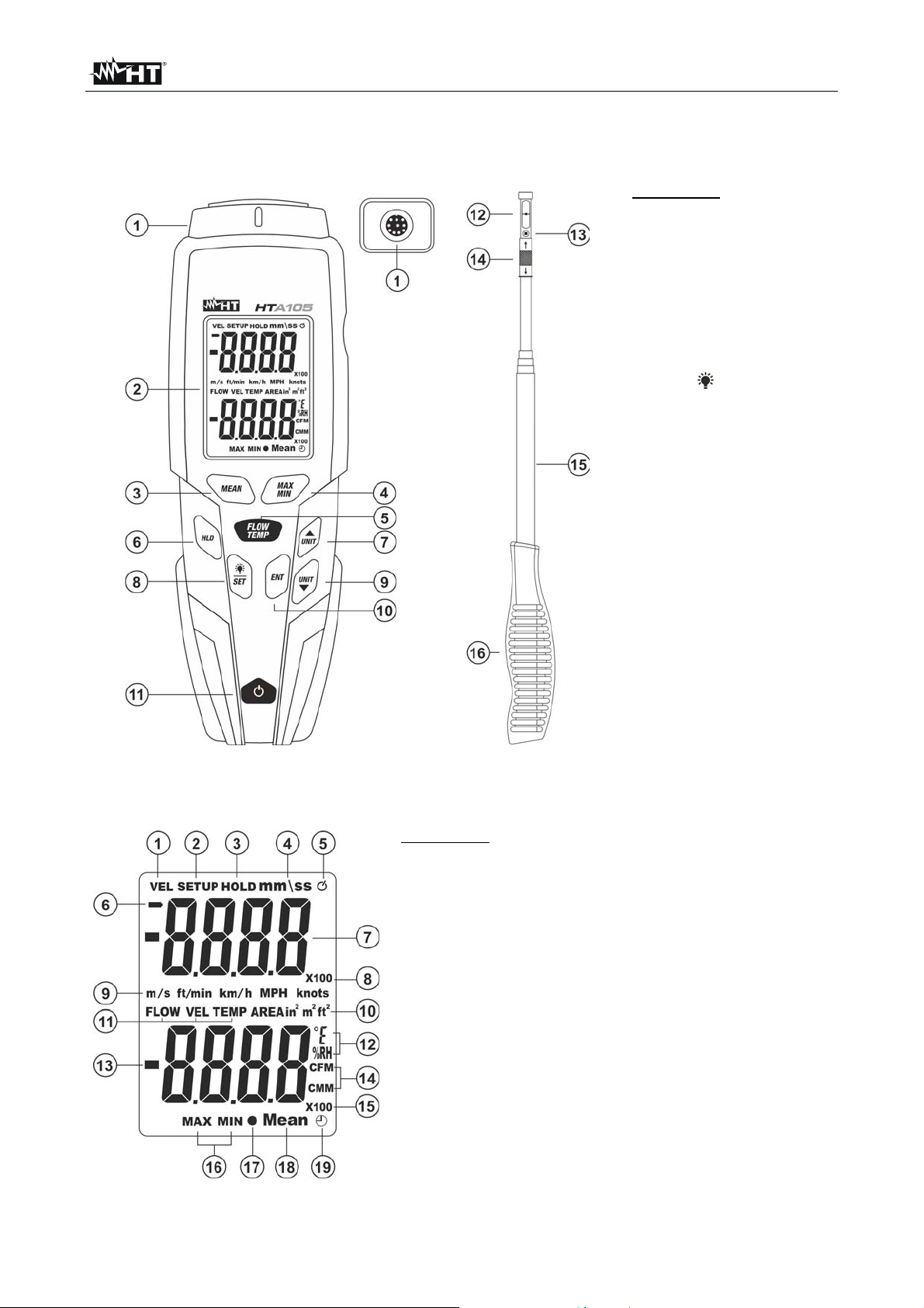
4.1. DESCRIPTION OF THE INSTRUMENT
CAPTION:
1. Input terminal for
telescopic probe
2. LCD display
3. Key MEAN
4. Key MAXMIN
5. Key FLOW/TEMP
6. Key HLD
7. Key UNIT
8. Key
9. Key UNIT
10. Key ENT
11. Key ON/OFF
12. Hot-wire sensor
13. Temperature sensor
14. Sliding sensor
protection
15. Extensible telescopic
probe
16. Handle of telescopic
probe
/SET
Fig. 1: Description of the instrument
4.2. DESCRIPTION OF THE DISPLAY
CAPTION:
1. Speed measurement
2. Active Settings
3. Active Data HOLD
4. Indication of
5. Indication of active Auto
6. Low battery symbol
7. Main display
8. Main display multiple
9. Speed measuring unit
10. Area measuring unit
11. Secondary display data
12. Temp/Humidity meas.
icon
minutes/seconds
Power OFF
unit
13. Secondary display
14. Flow rate
measuring unit
15. Secondary display
multiple
16. Activation of MAX
and MIN
measurements
17. Activation of
average calculation
18. Active Average
calculation function
19. Indication of active
calculation of
average over time
Fig. 2: Display description
EN - 4
Page 6

HTA105
4.3. DESCRIPTION OF FUNCTION KEYS
4.3.1. ON/OFF key
Pressing key ON/OFF allows turning on/off the instrument. Upon start-up, the instrument
carries out a countdown of 3s before displaying the measuring screen, in order to allow for
the internal sensors’ heating.
4.3.2. Key HLD
Pressing key HLD activates/deactivates function HOLD, i.e. the value of the quantities
measured on both displays is frozen on the main display. The symbol “HOLD” is shown on
the top of the display.
4.3.3. Key /SET
Pressing key /SET allows activating/deactivating the display’s backlight.
Pressing and holding (>2s) key /SET allows accessing section Settings (see § 4.4). A
new long pressing of the key allows quitting and going back to measuring screen.
4.3.4. Key ENT
Key ENT (ENTER) allows confirming the value of the programmed parameters in section
Settings (see § 4.4).
4.3.5. Key UNIT
Pressing key UNIT allows selecting the measuring unit of air speed shown in the main
display among the options: m/s, ft/min, km/h, MPH, knots. The same key allows
selecting parameters within section Settings (see §4.4).
4.3.6. Key UNIT
Pressing key UNIT allows selecting the measuring unit of air temperature shown on the
secondary display between the options: °C (Celsius) and °F (Fahrenheit), selecting the
measuring unit of air volumetric flow rate between the options: CPM and CMM (see §).
The same key allows selecting parameters within section Settings (see § 4.4).
4.3.7. Key FLOW/TEMP
Pressing key FLOW/TEMP allows selecting measuring units for air temperature (TEMP),
air volumetric flow rate (FLOW) (see § 5.2) and air humidity (%RH) displayed in the
secondary display.
4.3.8. Key MAXMIN
Cyclically pressing key MAXMIN activates the detection of Maximum and Minimum value
of the selected quantities (air speed, temperature, humidity and volumetric flow rate). Upon
each pressing of the key, the secondary display shows the maximum and minimum value
of the quantity, which is dynamically updated and shown together with the symbol
associated to the selected function: “MAX” for maximum value and “MIN” for minimum
value. Pressing and holding (>2s) key MAXMIN allows quitting the function. The key is not
active in the instrument’s programming.
4.3.9. Key MEAN
Pressing key MEAN allows activating the function for calculating the average over time
and by spots of the values of the quantities measured by the instrument (air speed,
temperature, humidity and volumetric flow rate) (see § 5.3).
EN - 5
Page 7
HTA105
4.4. INSTRUMENT SETTINGS
The instrument allows programming the following functions:
Measuring unit of the area of the duct in volumetric flow rate measurements
Size of the duct in volumetric flow rate measurements
Disabling the Auto Power OFF function
1. Turning on the instrument by means of key ON/OFF
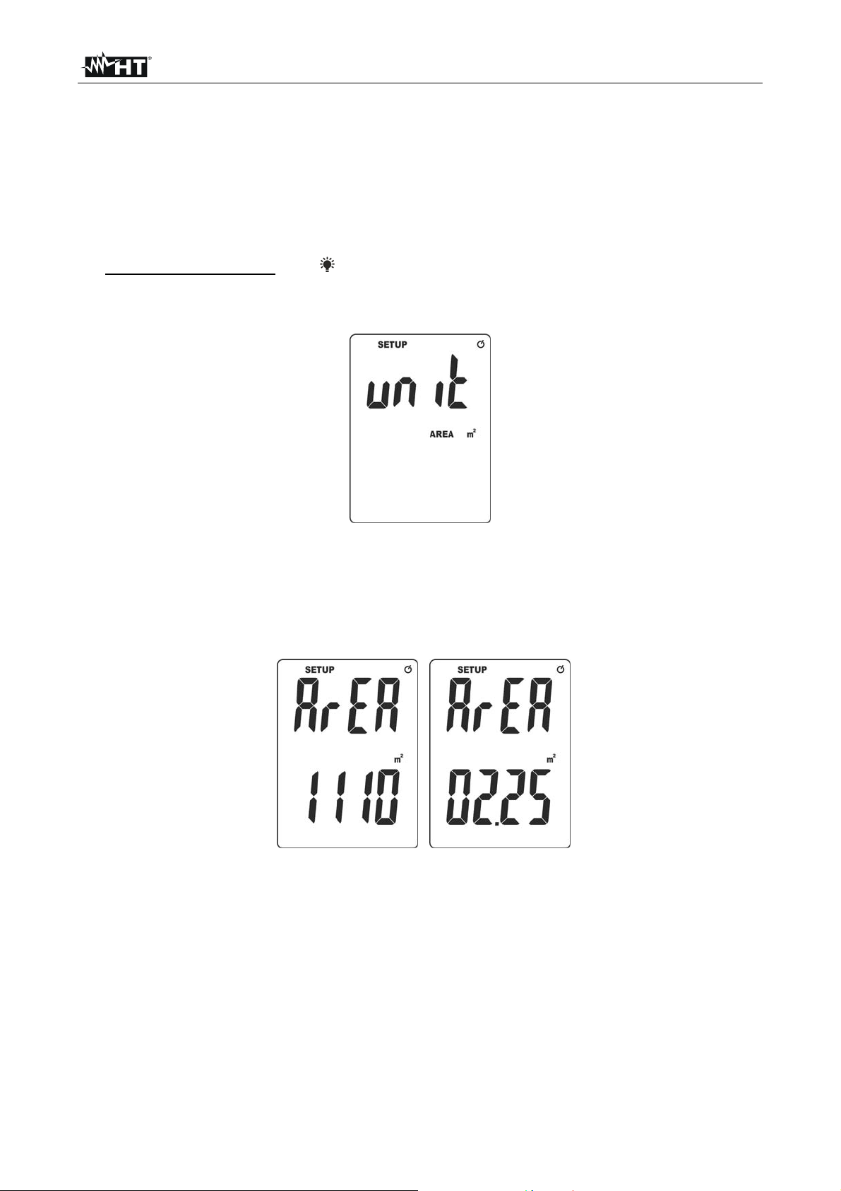
2. Press and hold (>2s) key /SET to enter the setting mode. The screen with the
indication of the currently set measuring unit of the area of the duct is shown on the
display (see Fig. 3)
Fig. 3: Setting the measuring unit of the area of the duct
3. Press key ENT. The unit flashes on the display
4. Press keys UNIT or UNIT to select the desired measuring unit among the options:
in2, m2 or ft2
5. Press key ENT to confirm. The screen in Fig. 4 – left side is shown on the display
Fig. 4: Setting of the value of duct area
6. Press key ENT. The value of area flashes on the display. Press keys UNIT or
UNIT to move the decimal point to the desired position and confirm with ENT. The
value of the last digit set flashes on the display
7. Press keys UNIT or UNIT to set the value of duct area in the range: 0.001 ÷ 9999
by proceeding from right to left and pressing key ENT to confirm each digit (see Fig. 4 –
right side) relevant, for example, to a square duct with a side of 1.5m x1.5m)
8. Press key ENT at the end, to confirm the value of duct area. The following screen (see
Fig. 5) is displayed.
EN - 6
Page 8
HTA105
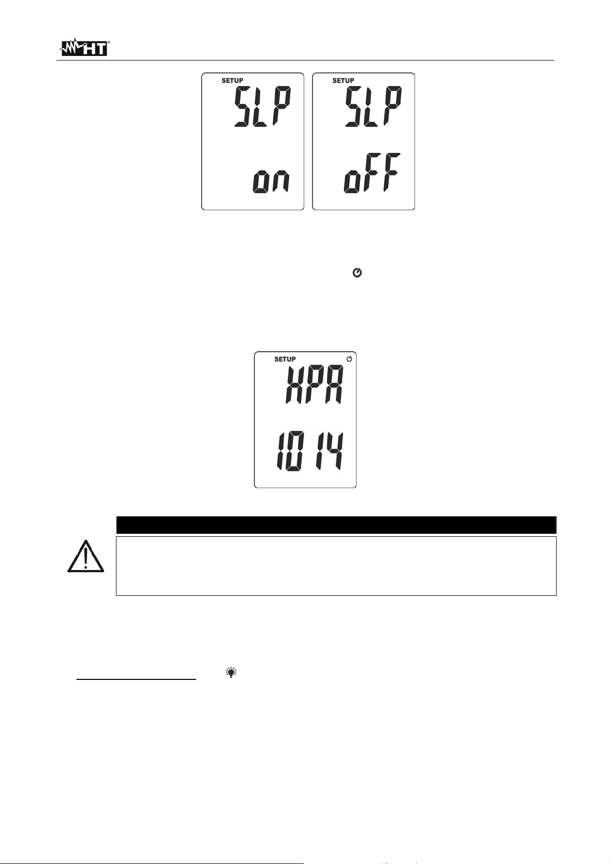
Fig. 5: Enabling/disabling the Auto Power Off function
9. Press keys UNIT or UNIT to select options: “on” (activation of Auto Power Off
function) or “oFF” (deactivation of Auto Power Off function)
10. With activated Auto Power Off function, symbol “ ” is shown on the display and the
instrument automatically turns off after approx. 20 minutes
’ idling
11. Press key ENT to confirm. The following screen (which allows to set the value of
atmospheric pressure expressed in hPA = mbar (not measured by the instrument) is
displayed
Fig. 6: Setting of atmospheric pressure value
CAUTION
The atmospheric pressure value is important for the necessary
compensation in order to obtain accurate air velocity measurements
The measurement of atmospheric pressure can be obtained with other
instruments or from local weather stations
12. Press key ENT. The value of last digit flashes on the display
13. Press key MEAN to move the decimal point to the desired position and the UNIT or
UNIT keys to set the desired value of atmospheric pressure and confirm with key
ENT
14. Press and hold (>2s) key /SET to quit section Settings and go back to measuring
screen.
EN - 7
Page 9
HTA105
5. OPERATING INSTRUCTIONS
5.1. MEASUREMENT OF AIR SPEED AND TEMPERATURE
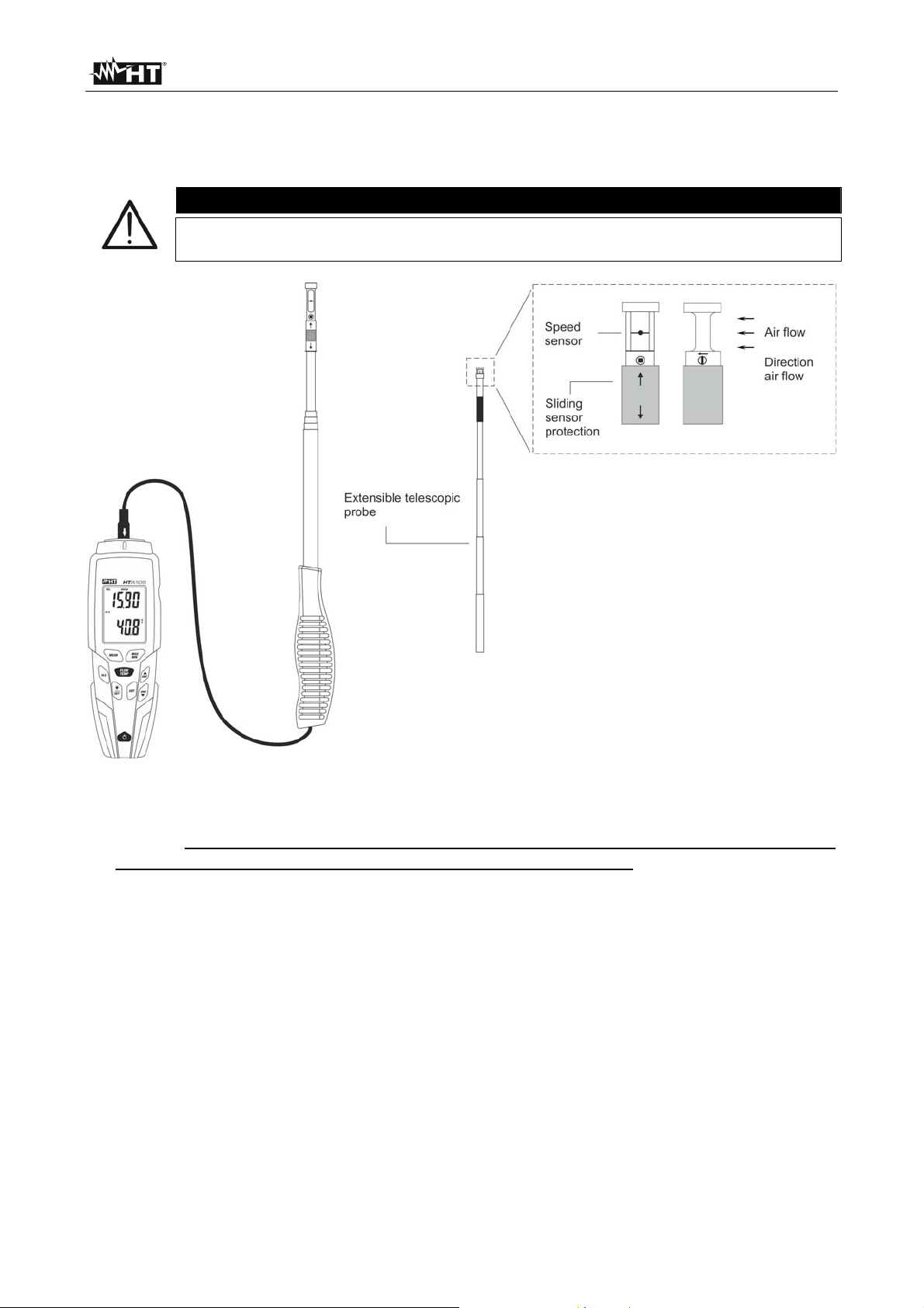
Do not touch not expose the internal sensors found on the top side of the
telescopic probe to mechanical shocks, in order to prevent damaging them.
CAUTION
Fig. 7: Measurement of air speed and temperature
1. Insert the external probe on the top side by means of the relevant terminal (see Fig. 1 –
part 1). Pay attention to the arrow found on the connector of the probe (see Fig. 7),
which must be directed towards the front side of the instrument
2. Switch on the instrument using key ON/OFF.
3. Press key UNIT to set the measuring unit of air speed (see § 4.3.5) and key UNIT
to set the measuring unit of air temperature (see § 4.3.6) on the secondary display after
press key FLOW/TEMP
4. Let the protection slide (see Fig. 1 – part 15) until the sensors are covered and check
that the indication on the main display is “0.00”. In case it is not, please carry out the
zeroing procedure (see § 4.3.2)
5. If necessary, expand the telescopic probe and position the air speed sensor in a
parallel direction to the air flow as indicated by the arrow found on the top of the probe
itself (see Fig. 7).
6. The value of air speed is indicated on the main display, while air temperature is shown
on the secondary display.
7. Press key HLD to freeze the reading on the display.
8. To use MAX, MIN functions, see § 4.3.8.
EN - 8
Page 10
HTA105
5.2. MEASURING VOLUMETRIC FLOW RATE AND AIR HUMIDITY
CAUTION
Do not touch not expose the internal sensors found on the top side of the
telescopic probe to mechanical shocks, in order to prevent damaging them.
1. Insert the external probe on the top side by means of the relevant terminal (see Fig. 1 –
part 1). Pay attention to the arrow found on the connector of the probe (see Fig. 7),
which must be directed towards the front side of the instrument
2. Switch on the instrument using key ON/OFF.
3. Press key UNIT to set air speed measuring unit (see § 4.3.5).
4. Set the measuring unit and the size of the area of the duct to be tested (see § 4.4).
5. Press key FLOW/TEMP to select measurement of volumetric flow rate. The symbol
“FLOW” is shown on the display.
6. Press key UNIT to select measuring unit
“CMM” or “CFM” on the secondary display
(see § 4.3.6).
7. Let the protection slide (see Fig. 1
– part 15) until the sensors are covered and check
that the indication on the main display is “0.00”. In case it is not, please carry out the
zeroing procedure (see § 4.3.2)
8. If necessary, expand the telescopic probe and position the air speed sensor in a
parallel direction to the air flow as indicated by the arrow found on the top of the probe
itself (see Fig. 7).
9. The value of air speed is indicated on the instrument’s main display.
10. The value of air flow rate is indicated on the instrument’s secondary display.
11. Press key FLOW/TEMP to select measurement of air humidity. The symbol “%RH” is
shown on the display.
12. The value of air humidity is indicated on the instrument’s secondary display.
13. Press key HLD to freeze the reading on the display.
14. To use MAX, MIN functions, see § 4.3.8.
EN - 9
Page 11
HTA105
5.3. CALCULATING AVERAGE VALUES OF QUANTITIES
5.3.1. Average value calculated by spots
CAUTION
Do not touch not expose the internal sensors found on the top side of the
telescopic probe to mechanical shocks, in order to prevent damaging them.
1. Insert the external probe on the top side by means of the relevant terminal (see Fig. 1 –
part 1). Pay attention to the arrow found on the connector of the probe (see Fig. 7),
which must be directed towards the front side of the instrument
2. Switch on the instrument using key ON/OFF.
3. Press key UNIT to set air speed measuring unit (see § 4.3.5).
4. Press key FLOW/TEMP to select average values of measurements of volumetric flow
rate, air temperature or humidity to be carried out with the same procedure as for air
speed.
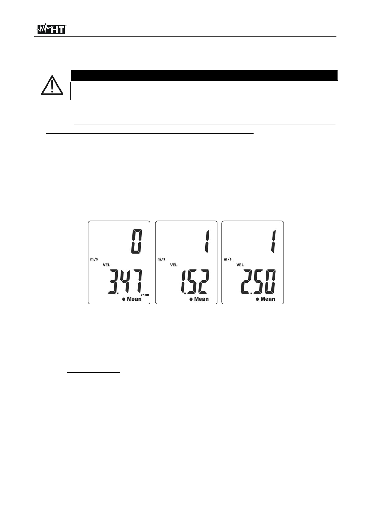
5. Press key MEAN. Symbols “” and “Mean” are shown in the bottom part of the display,
while the number of the measuring spots are show on the main display.
6. Carry out the first measurement of air speed as described in § 5.1 and press key ENT.
The value of the first spot is shown on the secondary display (see Fig. 8 – left part).
Fig. 8: Calculation of the average value of speed by spots
7. Carry out the second measurement of air speed as described in § 5.1 and press key
ENT. The value of the second spot is shown on the secondary display (see Fig. 8 –
middle)
8. Carry out other possible air speed measurements following the same procedures and,
at the end, press key MEAN. Symbols “” and “Mean” flash on the display and the value
of the arithmetic mean is shown on the secondary display (see Fig. 8 – right side).
9. Press key MEAN again to go back to the normal measuring screen.
EN - 10
Page 12
HTA105
5.3.2. Average value calculated over time
CAUTION
Do not touch not expose the internal sensors found on the top side of the
telescopic probe to mechanical shocks, in order to prevent damaging them.
1. Insert the external probe on the top side by means of the relevant terminal (see Fig. 1 –
part 1). Pay attention to the arrow found on the connector of the probe (see Fig. 7),
which must be directed towards the front side of the instrument
2. Switch on the instrument using key ON/OFF.
3. Press key UNIT to set air speed measuring unit (see § 4.3.5).
4. Press key FLOW/TEMP to select average values of measurements of volumetric flow
rate, air temperature or humidity to be carried out with the same procedure as for air
speed.
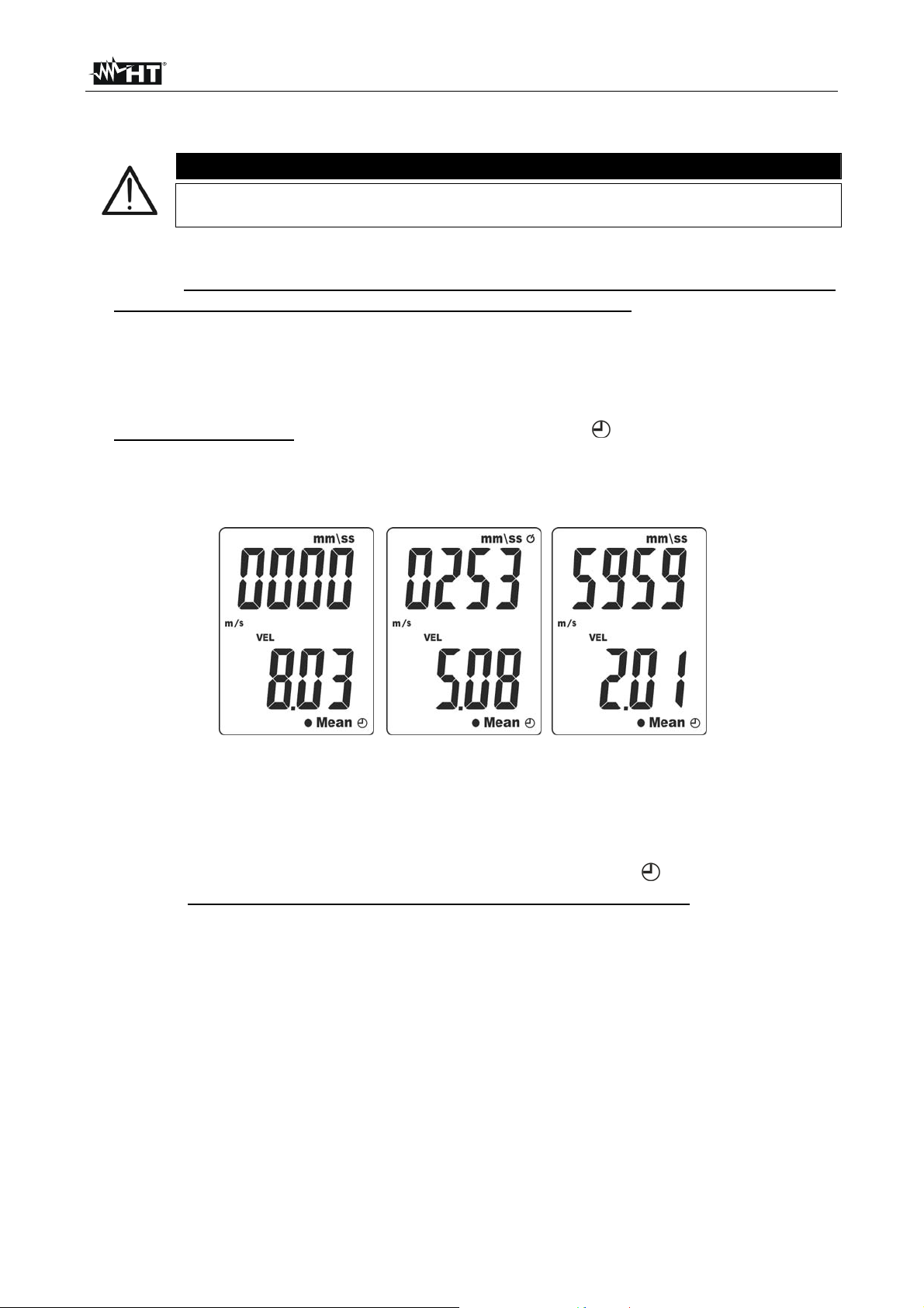
5. Press and hold (>2s) key MEAN. Symbols “Mean” and “ ” and air speed are shown
respectively in the bottom part of the display and on the secondary display, while
symbols “0000” and “mm/ss” (timer expressed in minutes/seconds) are shown on the
main display (see Fig. 9 – left part).
Fig. 9: Average value of speed calculated over time
6. Press key ENT to activate the measuring time (range: 1s ÷ 59min, 59sec) indicated on
the main display, while air speed measurement is running (see Fig. 9
– middle, referred
to a measuring time of 2min e 53s)
7. Press key ENT key again to stop and/or extend measuring time
8. Press key MEAN to stop measurement. Symbols “Mean” and “ ” flash on the display
and the Average value calculated over time with sample rate of 1s is shown on the
secondary display (see Fig. 9 – right side)
9. For measuring time over 20 minutes (see Fig. 9 – right side) is necessary to disable
the Auto Power OFF feature (see § 4.4)
EN - 11
Page 13
HTA105
6. MAINTENANCE
6.1. GENERAL INFORMATION
1. While using and storing the instrument, carefully observe the recommendations listed
in this manual in order to prevent possible damage or danger during use.
2. Do not use the instrument in environments with high humidity levels or high
temperatures. Do not expose to direct sunlight.
3. Always switch off the instrument after use. In case the instrument is not to be used for a
long time, remove the battery to avoid liquid leaks that could damage the instrument's
internal circuits.
6.2. REPLACING THE BATTERY
When the LCD display shows symbol “ ”, it is necessary to replace the battery.
Only exper t technicians should perform this operation. Before carrying out
this operation, make sure you have removed the probe from the input
terminal.
When symbol “ ” is shown on the display, air speed indication is
flashing and, in these conditions, the measured value does not comply
with the declared accuracy indications.
1. Switch off the instrument
2. Remove the probe from the input terminal
3. Remove the battery compartment cover
4. Disconnect the battery from the connector.
5. Connect the new battery to the connector, and pay attention to correct polarity
6. Restore the battery compartment cover to its position.
7. Do not scatter old batteries into the environment. Use the relevant containers for
battery disposal.
6.3. CLEANING THE INSTRUMENT
Use a soft and dry cloth to clean the instrument. Never use wet cloths, solvents, water, etc.
6.4. END OF LIFE
WARNING: this symbol found on the instrument indicates that the appliance, its
accessories and the battery must be collected separately and correctly disposed
of.
CAUTION
EN - 12
Page 14
HTA105
7. TECHNICAL SPECIFICATIONS
7.1. TECHNICAL CHARACTERISTICS
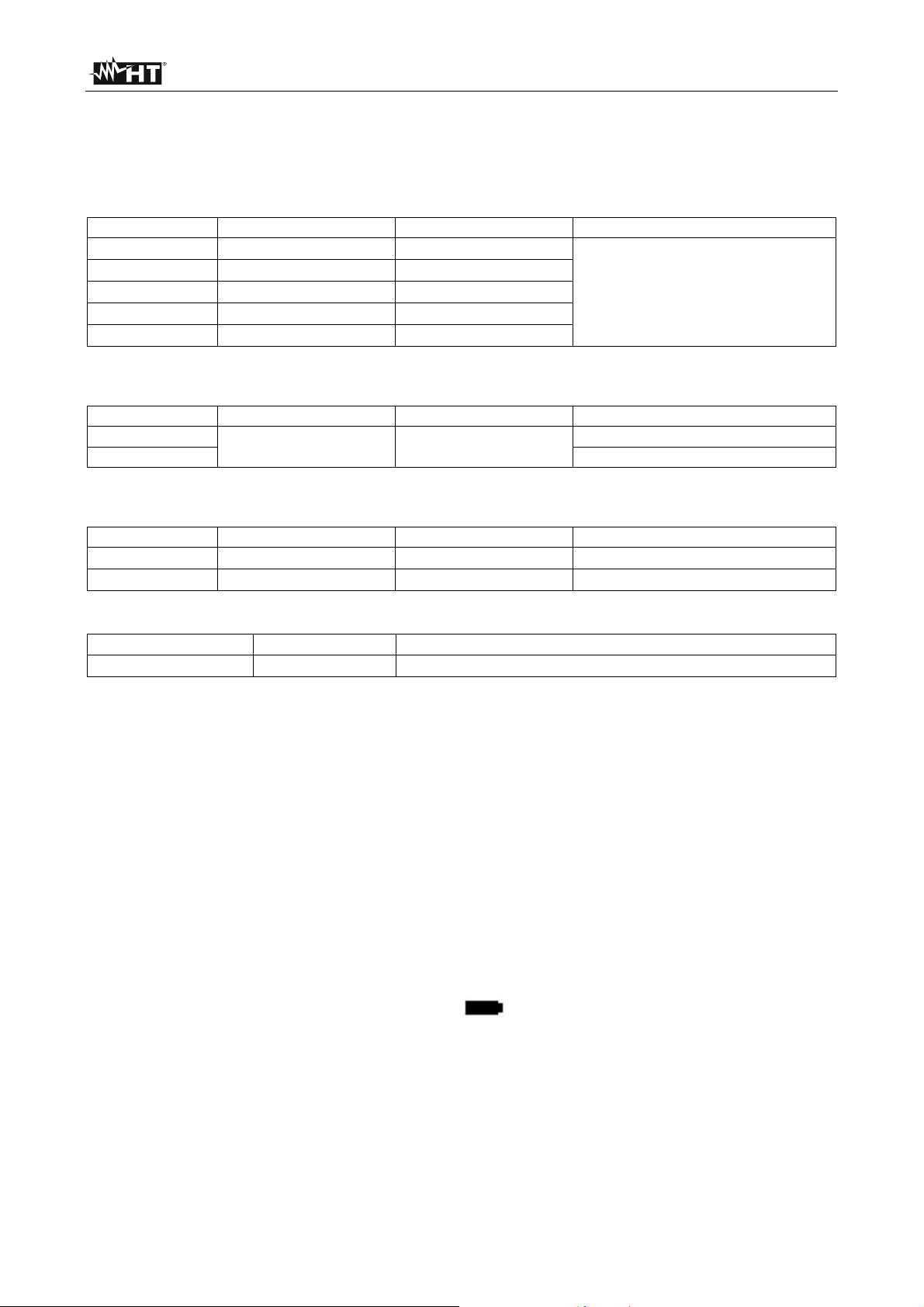
Accuracy is calculated as ±[%reading + value] at 25°C, <80%RH
Measurement of air speed through hot-wire sensor
Measuring unit Range Resolution Accuracy
m/s
km/h
ft/min
MPH
knots
m/s = meters/second ; km/h = kilometers/hour ; ft/min = feet/minute ; MPH = miles/hour ; knots = nautical miles/hour
0.10 20.00
0.4 72.0
20 3937
0.3 44.7
0.2 39.0
Measurement of air volumetric flow rate
Measuring unit Range Resolution Description
CMM
CFM CMM = ft3/min
CMM = air speed (m/s) * Area (m2) * 60 ; CFM = air speed (ft/min) * Area (ft2)
0 99999
Measurement of air temperature
Measuring unit Range Resolution Accuracy
°C
°F
0.0°C 50.0°C
32.0°F 122.0°F
Measurement of air relative humidity
Range Resolution Accuracy
0%RH 100%RH
0.1%RH
7.1.1. General characteristics
Mechanical characteristics
Size (L x W x H): 190 x 65 x 45mm (7 x 3 x 2in)
Length of telescopic probe: from 13cm to 1m (from 5in to 3ft)
Length of telescopic probe cable: 170cm (6ft)
Diameter of telescopic probe: 12mm (0.4in)
Weight (battery included): 240g (8ounces)
Weight of telescopic probe: 165g (6ouces)
Air speed sensor: hot-wire
Air temperature sensor: digital sensor
Mechanical protection: IP40
Power supply
Battery type: 1x9V alkaline battery type NEDA 1604 IEC 6FL22
Low battery indication: symbol “ ” on the display
Battery life: approx. 15hours (backlight ON), approx. 20 hours
(backlight OFF)
Out-of-range indication: “OL.” symbol on the display
Auto Power OFF: after 20 minutes' idling
Display
Main display: 4 LCD plus decimal point, sign, backlit
Secondary display: 4 LCD plus decimal point, sign, backlit
Updating speed: approx. 0.8s
0.01m/s
0.1km/h
1ft/min
0.1MPH
0.1knots
0.001 ÷ 100
0.1°C
0.1°F
(5%rdg+ 0.03)
CMM = m3/min
1°C
1.8°F
5%RH
EN - 13
Page 15

HTA105
7.2. ENVIRONMENT
7.2.1. Environmental conditions for use
Reference temperature: 25°C (77°F)
Operating temperature: 0°C ÷ 50°C (32°F ÷ 122°C)
Allowable relative humidity: <80%RH
Storage temperature: -10°C ÷ 60°C (14°F ÷ 140°F)
Storage humidity: <80%RH
Max operating altitude: 2000m (6562ft)
This instrument complies with European Directive EMC 2014/30/EU
This instrument satisfies the requirements of European Directive 2011/65/EU
(RoHS) and 2012/19/EU (WEEE).
7.3. ACCESSORIES
External telescopic probe
Battery
User manual
Transport case
EN - 14
Page 16
HTA105
8. ASSISTANCE
8.1. WARRANTY CONDITIONS
This instrument is warranted against any material or manufacturing defect, in compliance
with the general sales conditions. During the warranty period, defective parts may be
replaced. However, the manufacturer reserves the right to repair or replace the product.
Should the instrument be returned to the After-sales Service or to a Dealer, transport will
be at the Customer's charge. However, shipment will be agreed in advance. A report will
always be enclosed to a shipment, stating the reasons for the product's return. Only use
original packaging for shipment; any damage due to the use of non-original packaging
material will be charged to the Customer. The manufacturer declines any responsibility for
injury to people or damage to property.
The warranty shall not apply in the following cases:
Repair and/or replacement of accessories and batteries (not covered by warranty)
Repairs that may become necessary as a consequence of an incorrect use of the
instrument or due to its use together with non-compatible appliances.
Repairs that may become necessary as a consequence of improper packaging.
Repairs which may become necessary as a consequence of interventions performed
by unauthorized personnel.
Modifications to the instrument performed without the manufacturer's explicit
authorization.
Use not provided for in the instrument's specifications or in the instruction manual.
The content of this manual cannot be reproduced in any form without the manufacturer's
authorization.
Our products are patented and our trademarks are registered. The manufacturer
reserves the right to make changes in the specifications and prices if this is due to
improvements in technology.
8.2. ASSISTANCE
If the instrument does not operate properly, before contacting the After-sales Service,
please check the conditions of the battery and replace it, if necessary. Should the
instrument still operate improperly, check that the product is operated according to the
instructions given in this manual. Should the instrument be returned to the After-sales
Service or to a Dealer, transport will be at the Customer's charge. However, shipment will
be agreed in advance. A report will always be enclosed to a shipment, stating the reasons
for the product's return. Only use original packaging for shipment; any damage due to the
use of non-original packaging material will be charged to the Customer.
EN - 15
 Loading...