

Page 1

ENGLISH
User manual
Copyright HT ITALIA 2018 Release EN 1.00 - 31/10/2018
Page 2

Page 3

NEPTUNE
TABLE OF CONTENTS
1. PRECAUTIONS AND SAFETY MEASURES ............................................................... 2
1.1. Preliminary instructions ..................................................................................................... 2
1.2. During use ......................................................................................................................... 3
1.3. After use ............................................................................................................................ 3
1.4. Definition of Measurement (Overvoltage) category ........................................................... 3
2. GENERAL DESCRIPTION ........................................................................................... 4
2.1. Measuring average values andTRMS values .................................................................... 4
2.2. Definition of true root mean square value and Crest factor ............................................... 4
3. PREPARATION FOR USE ........................................................................................... 5
3.1. Initial checks ...................................................................................................................... 5
3.2. Instrument power supply ................................................................................................... 5
3.3. Storage .............................................................................................................................. 5
4. NOMENCLATURE ........................................................................................................ 6
4.1. Description of the instrument ............................................................................................. 6
4.1.1. Instrument’s initial screen ........................................................................................................... 6
4.2. Description of function keys .............................................................................................. 7
4.2.1. Key GO/HOLD ............................................................................................................................ 7
4.2.2. Key H/H%/H ............................................................................................................................ 7
4.2.3. Key MODE/MXMNPK ................................................................................................................. 8
4.2.4. Keys / e / ZERO .............................................................................................................. 8
4.2.5. Key VTEST/LIM .......................................................................................................................... 8
4.2.6. LoZ function ................................................................................................................................ 9
4.2.7. AC+DC function .......................................................................................................................... 9
4.2.8. Inrush current function (INRUSH) .............................................................................................. 9
4.2.9. Disabling the Auto Power Off function ........................................................................................ 9
4.2.10. Setting the full scale for flexible clamp transducer ................................................................... 10
5. OPERATING INSTRUCTIONS ................................................................................... 11
5.1. DC voltage measurement ................................................................................................ 11
5.2. AC, AC+DC voltage measurement ................................................................................. 12
5.3. AC, DC, AC+DC voltage with low impedance (LoZ) ....................................................... 13
5.4. Resistance measurement and continuity test .................................................................. 14
5.5. Phase sequence and phase concordance with 1 terminal .............................................. 15
5.6. Measurement of insulation resistance ............................................................................. 17
5.7. Continuity of protective conductors with 200mA ............................................................. 23
5.7.1. Function ZERO – Zeroing of test cable resistance ................................................................... 27
5.8. Measurement of DC, AC, AC+DC, INRUSH current with clamp transducers ................. 29
6. MAINTENANCE ......................................................................................................... 33
6.1. Battery replacement ........................................................................................................ 33
6.2. Cleaning the instrument .................................................................................................. 33
6.3. End of life ........................................................................................................................ 33
7. TECHNICAL SPECIFICATIONS ................................................................................ 34
7.1. Technical characteristics ................................................................................................. 34
7.1.1. General characteristics ............................................................................................................. 36
7.2. Environmental conditions for use .................................................................................... 36
7.3. Accessories ..................................................................................................................... 36
8. ASSISTANCE ............................................................................................................. 37
8.1. Warranty conditions ......................................................................................................... 37
8.2. Assistance ....................................................................................................................... 37
9. THEORETICAL APPENDIXES ................................................................................... 38
9.1. Continuity of protective conductors ................................................................................. 38
9.2. Measurement of insulation resistance ............................................................................. 39
9.2.1. Polarization Index (PI) .............................................................................................................. 42
9.2.2. Dielectric Absorption Ratio (DAR) ............................................................................................ 42
9.3. Voltage and current harmonics ....................................................................................... 43
EN - 1
Page 4

NEPTUNE
1. PRECAUTIONS AND SAFETY MEASURES
The instrument has been designed in compliance with directive IEC/EN61010-1 relevant to
electronic measuring instruments. For your safety and in order to prevent damaging the
instrument, please carefully follow the procedures described in this manual and read all
notes preceded by symbol with the utmost attention.
Before and after carrying out measurements, carefully observe the following instructions:
Do not carry out any measurement in humid environments.
Do not carry out any measurements in case gas, explosive materials or flammables are
present, or in dusty environments.
Avoid any contact with the circuit being measured if no measurements are being
carried out.
Avoid contact with exposed metal parts, with unused measuring probes, etc.
Do not carry out any measurement in case you find anomalies in the instrument such
as deformation, breaks, substance leaks, absence of display on the screen, etc.
Pay special attention when measuring voltages higher than 50V, since a risk of
electrical shock exists.
In this manual, and on the instrument, the following symbols are used:
Warning: observe the instructions given in this manual; improper use could
damage the instrument or its components.
High voltage danger: electrical shock hazard.
Double-insulated meter
AC voltage or current
DC voltage or current
Connection to earth
1.1. PRELIMINARY INSTRUCTIONS
This instrument has been designed for use in environments of pollution degree 2.
It can be used for VOLTAGE and CURRENT measurements on installations with CAT
IV 600V, CAT III 1000V to earth and between inputs.
We recommend following the normal safety rules devised by the procedures for
carrying out operations on live systems and using the prescribed PPE to protect the
user against dangerous currents and the instrument against incorrect use.
In case the lack of indication of the presence of voltage may represent a danger for the
operator, always carry out a continuity measurement before carrying out the
measurement on the live system, in order to confirm the correct connection and
condition of the leads.
Only the leads supplied with the instrument guarantee compliance with the safety
standards. They must be in good conditions. If necessary, only replace them with
original HT accessories.
Do not test circuits exceeding the specified voltage limits.
Do not perform any test under environmental conditions exceeding the limits indicated
in § 6.2.1
Check that the battery is correctly inserted.
Make sure that the LCD display and the rotary switch indicate the same function.
EN - 2
Page 5

NEPTUNE
1.2. DURING USE
Please carefully read the following recommendations and instructions:
CAUTION
Failure to comply with the caution notes and/or instructions may damage
the instrument and/or its components or be a source of danger for the
operator.
Before activating the rotary switch, disconnect the test leads from the circuit being
measured.
When the instrument is connected to the circuit being measured, do not touch any
unused terminal.
During current measurement, any other current near the clamps may affect
measurement precision.
When measuring current, always put the conductor as near as possible to the middle of
the clamp jaw, to obtain the most accurate reading.
Do not measure resistance in case external voltages are present; even if the
instrument is protected, an excessive voltage may cause malfunction.
Before attempting any resistance measurement, cut off power supply from the circuit to
be measured and make sure that all capacitors are discharged, if present.
While measuring, if the value or the sign of the quantity being measured remain
unchanged, check if the HOLD function is enabled.
1.3. AFTER USE
When measurement is complete, set the rotary switch to OFF
If the instrument is not to be used for a long time, remove the batteries
1.4. DEFINITION OF MEASUREMENT (OVERVOLTAGE) CATEGORY
Standard “IEC/EN61010-1: Safety requirements for electrical equipment for measurement,
control and laboratory use, Part 1: General requirements”, defines what measurement
category, commonly called overvoltage category, is. § 6.7.4 reads: Circuits are divided into
the following measurement categories:
Measurement category IV is for measurements performed at the source of the low-
voltage installation.
Examples are electricity meters and measurements on primary overcurrent protection
devices and ripple control units.
Measurement category III is for measurements performed on installations inside
buildings.
Examples are measurements on distribution boards, circuit breakers, wiring, including
cables, bus-bars, junction boxes, switches, socket-outlets in the fixed installation, and
equipment for industrial use and some other equipment, for example, stationary motors
with permanent connection to fixed installation.
Measurement category II is for measurements performed on circuits directly
connected to the low-voltage installation.
Examples are measurements on household appliances, portable tools and similar
equipment.
Measurement category I is for measurements performed on circuits not directly
connected to MAINS.
Examples are measurements on circuits not derived from MAINS, and specially
protected (internal) MAINS-derived circuits. In the latter case, transient stresses are
variable; for that reason, the standard requires that the transient withstand capability of
the equipment is made known to the user.
EN - 3
Page 6

NEPTUNE
2. GENERAL DESCRIPTION
The instrument carries out the following measurements:
DC / AC, AC+DC TRMS voltage
DC / AC / AC+DC TRMS voltage with low impedance (LoZ)
DC / AC / AC+DC TRMS current with standard clamp transducer
AC TRMS current with flexible clamp transducers
Automatic recognition of AC and DC quantities
Inrush current (Dynamic INRUSH - DIRC)
Current/voltage harmonics up to the 25th and THD% calculation
Resistance and Continuity test
Current and voltage frequency
Insulation resistance with test voltage 50,100,250,500,1000VDC
Measurement of Polarization Index (PI) and Dielectric Absorption Ratio (DAR)
Continuity of protective conductor with 200mA
Phase sequence with 1 terminal
Each of these functions can be selected by means of the appropriate switch. The
instrument is also equipped with function keys (see § 4.2), an analogue bargraph and
backlight. The instrument is also equipped with an Auto Power OFF function (which can be
disabled), which automatically switches off the instrument 15 minutes after the last time a
function key was pressed or the rotary switch was turned. To switch on the instrument
again, turn the rotary switch.
2.1. MEASURING AVERAGE VALUES ANDTRMS VALUES
Measuring instruments of alternating quantities are divided into two big families:
AVERAGE-VALUE meters: instruments measuring the value of the sole wave at
fundamental frequency (50 or 60 Hz).
TRMS (True Root Mean Square) VALUE meters: instruments measuring the TRMS
value of the quantity being tested.
With a perfectly sinusoidal wave, the two families of instruments provide identical results.
With distorted waves, instead, the readings shall differ. Average-value meters provide the
RMS value of the sole fundamental wave; TRMS meters, instead, provide the RMS value
of the whole wave, including harmonics (within the instruments bandwidth). Therefore, by
measuring the same quantity with instruments from both families, the values obtained are
identical only if the wave is perfectly sinusoidal. In case it is distorted, TRMS meters shall
provide higher values than the values read by average-value meters.
2.2. DEFINITION OF TRUE ROOT MEAN SQUARE VALUE AND CREST FACTOR
The root mean square value of current is defined as follows: “In a time equal to a period,
an alternating current with a root mean square value of 1A intensity, circulating on a
resistor, dissipates the same energy that, during the same time, would be dissipated by a
direct current with an intensity of 1A". This definition results in the numeric expression:
Tt
0
1
2
dttg
G=
T
The Crest Factor is defined as the relationship between the Peak Value of a signal and its
RMS value: CF (G)=
sinusoidal wave it is 2=1.41. In case of distortion, the Crest Factor takes higher values
as wave distortion increases.
)(
t
0
The root mean square value is indicated with the acronym RMS.
G
p
This value changes with the signal waveform, for a purely
G
RMS
EN - 4
Page 7

NEPTUNE
3. PREPARATION FOR USE
3.1. INITIAL CHECKS
Before shipping, the instrument has been checked from an electric as well as mechanical
point of view. All possible precautions have been taken so that the instrument is delivered
undamaged.
However, we recommend generally checking the instrument in order to detect possible
damage suffered during transport. In case anomalies are found, immediately contact the
forwarding agent.
We also recommend checking that the packaging contains all components indicated in §
6.3.1. In case of discrepancy, please contact the Dealer.
In case the instrument should be returned, please follow the instructions given in § 7.
3.2. INSTRUMENT POWER SUPPLY
The instrument is supplied with 4x1.5V alkaline batteries type AAA IEC LR03, included in
the package. When batteries are flat, the symbol
the batteries, see § 6.1.
3.3. STORAGE
In order to guarantee precise measurement, after a long storage time, wait for the
instrument to come back to normal condition (see § 6.2.1).
“ ” is shown on the display. To replace
EN - 5
Page 8
NEPTUNE
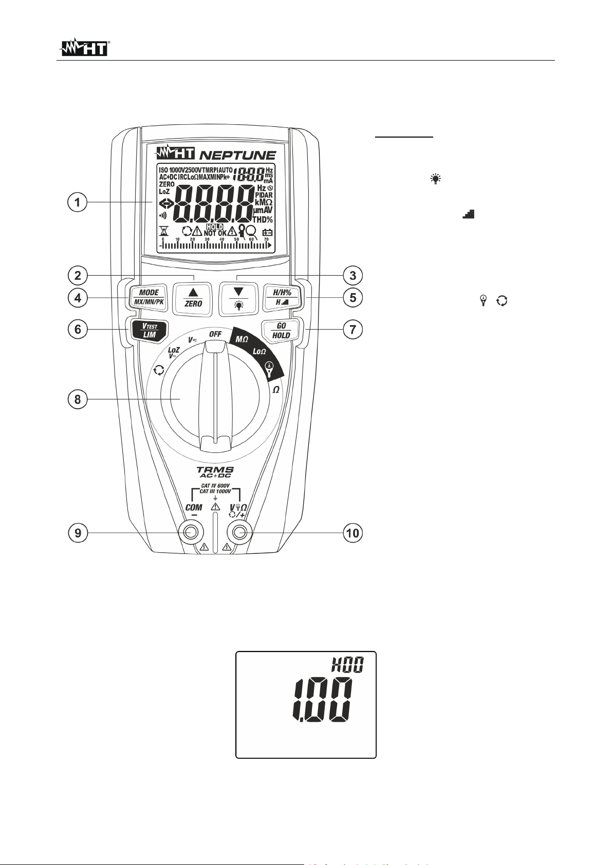
4. NOMENCLATURE
4.1. DESCRIPTION OF THE INSTRUMENT
CAPTION:
1. LCD display
2. Key / ZERO
3. Key/
4. Key MODE/MXMNPK
5. Key H/H%/H
6. Key V
TEST/LIM
7. Key GO/HOLD
8. Rotary selector switch
9. Input terminal COM/
10. Input terminal V /+
Fig. 1: Description of the instrument
4.1.1. Instrument’s initial screen
1. Turn the rotary switch to any position to switch on the instrument. The following initial
screen is shown on the display for a few seconds to identify the internal Hardware and
Firmware version.
Fig. 2: Instrument’s initial screen
2. Turn the rotary switch to OFF to switch off the instrument.
EN - 6
Page 9
NEPTUNE
4.2. DESCRIPTION OF FUNCTION KEYS
4.2.1. Key GO/HOLD
Pressing the key GO/HOLD (for functions V , LoZV , and ) makes the instrument
hold the value of the quantity shown on the display. The message “HOLD” appears on the
display. Press the key again to exit the function. Pressing key GO/HOLD (for functions
M, Lo, , IRC) activates the corresponding measurement.
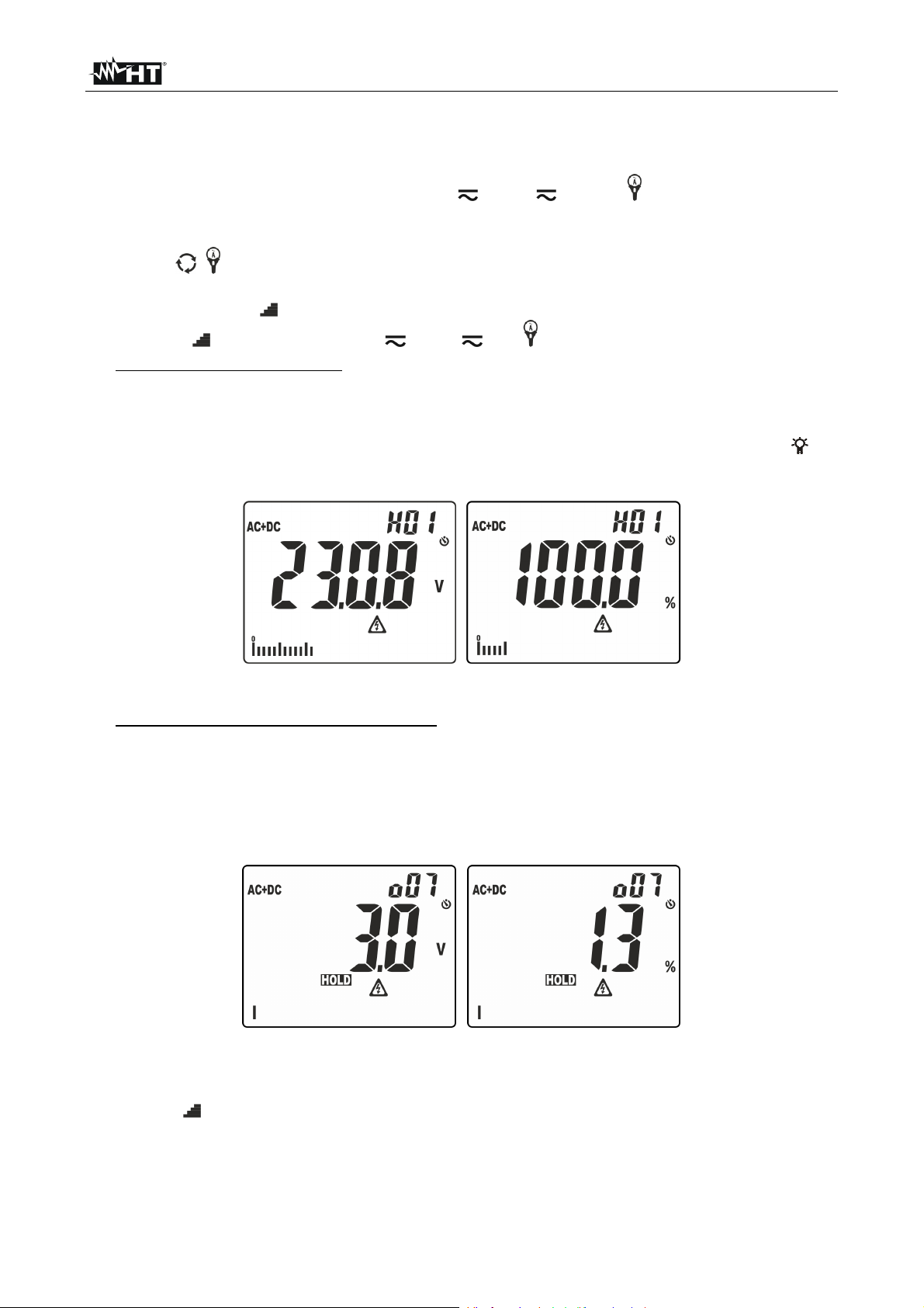
4.2.2. Key H/H%/H
Key H/H%/H (active in positions V , LoZV and ) allows the following operations:
Simple pressing of the key to display the amplitude of voltage and current harmonics
up to the 25th (Hdc, H01… H25) in absolute or percentage format in relationship with
the fundamentals of input signals (for voltage values VAC >0.5V and current values AC
> 0.5A and frequency in the range 42.5Hz ÷ 69Hz) and the percentage value of
parameter THD% (see § 9.3) as shown in Fig. 3. Use keys /ZERO and /
to
increase/decrease the order of the harmonic.
Fig. 3: Display of amplitude of harmonic analysis
Long pressing of the key (at least 2s) in order to activate the H2O (Higher Harmonic
Ordering) ordering function of the amplitude of harmonics. In these conditions, function
“HOLD” is automatically activated and symbol “o” appears next to the displayed
harmonic order to indicate that the Ordering function is activated. The bargraph is
disabled and the instrument shows the value of amplitude of all the harmonics between
the DC value and the 25th, fundamental harmonic excluded, in a decreasing order
starting from the harmonic with the highest amplitude, as shown in Fig. 4
Fig. 4: Display of ordering of amplitude of harmonic analysis
In the example in Fig. 4, the harmonic with the highest value corresponds to the 7th.
Press key to observe the amplitude of the remaining harmonics and press key
H/H%/H again to switch between display in absolute and percentage values. Turn
the rotary switch to exit the function.
EN - 7
Page 10
NEPTUNE
4.2.3. Key MODE/MXMNPK
A simple pressing of key MODE/MXMNPK allows for the following operations:
Selection of measuring modes “AUTO”, “AC”, “DC”, “AC+DC” and “FREQ” in positions
V , LoZV
Selection of measuring modes “AUTO”, “AC”, “DC” and “AC+DC”, “FREQ” and “IRC”
(see § 4.2.8) in position
Selection of clamp transducer type in current measurement between options “ ”
(optional standard clamp) and “ ” (optional flexible clamp) in position
Selection of measurements “AUTO” “TMR” and “PI” in position M (see § 5.6).
Selection of measurements “AUTO” and “TMR” in position Lo (see § 5.7).
Selection of measurement of Resistance “” or Continuity test “ ” in position
A long pressing (>2s) of key MODE/MXMNPK allows for the activation/deactivation of
continuous detection of maximum value (MAX), minimum value (MIN), positive peak (Pk+),
negative peak (Pk-) of the quantity (voltage or current) to be measured. The values are
constantly updated and are displayed cyclically every time the same key is pressed. This
function is not active in position . Press and hold key MODE/MXMNPK (>2s) or use the
selector to exit the function.
4.2.4. Keys / e / ZERO
A simple pressing of keys / and / ZERO allows for the following operations::
Setting of the full scale value of flexible clamp transducer (optional accessory - option
“ ” ) in position among values: 30A, 300A, 3000A for AC current measurement.
Setting of the full scale value of standard clamp transducer (option “ ” ) in position
among values: 1A, 10A, 30A, 40A, 100A, 200A, 300A, 400A, 1000A, 2000A, 3000A
for AC and DC current measurement.
Selection of harmonic order “DC ÷ 25°” in positions V , LoZV and
Selection of calculation time of RMS value in DIRC function (see § 4.2.8).
Setting of threshold values in positions M and Lo.
Once insulation measurement is complete, the results appear on the display (M,
Vgen, PI, DAR).
Long pressing (>2s) of key / allows activating/deactivating display backlight. This
function is activated in any position of the rotary switch and is automatically deactivated
after approx. 2 minutes
following operations:
’ idling. Long pressing (>2s) of key / ZERO allows for the
Zeroing of cable resistance in position Lo (see § 5.7)
Zeroing of cable resistance in position (see § 5.4)
4.2.5. Key VTEST/LIM
A simple pressing of key VTEST/LIM allows for the following operations:
Selecting test voltage in insulation measurement among the following options: 50V,
100V, 250V, 500V, 1000VDC in position M
Long pressing (>2s) of key VTEST/LIM allows for the following operations:
Setting the minimum threshold in insulation measurement among the following options:
no (no threshold), 0.10M, 0.230M, 0.50M, 1.00M, 100M in position M.
Setting the maximum threshold for continuity test in range: 0.05 ÷ 9.99 in position
Lo.
EN - 8
Page 11
NEPTUNE
4.2.6. LoZ function
This mode allows carrying out AC/DC voltage measurement with a low input impedance, in
order to eliminate wrong readings due to parasite voltages for capacitive couplings.
CAUTION
By plugging the instrument between the phase and earth conductor,
because of the low impedance of the instrument during measurement,
RCD protections may trip while carrying out the test. If this test is to be
carried out, first carry out a measurement of at least 5s between phase
and neutral in the presence of voltage
Do not leave the instrument connected for more than 1min
4.2.7. AC+DC function
The instrument is capable of measuring a possible presence of overlapping alternating
components on a generic direct waveform (voltage or current). This can be useful when
measuring typical impulsive signals of non-linear loads (e.g. welding machines, ovens,
etc.).
4.2.8. Inrush current function (INRUSH)
Measurement of inrush current (see § 5.8) is intended as the recognition of an event
detected upon exceeding of a trigger threshold. If the instant value exceeds this threshold
(fixed, equal to 1%FS clamp), the instrument shows on the display the maximum Peak
value (calculated in 1ms) and the maximum RMS value calculated with a time which can
be selected among options: 16.7ms, 20ms, 50ms, 100ms (default), 150ms, 175ms and
200ms.
4.2.9. Disabling the Auto Power Off function
In order to preserve internal batteries, the instrument switches off automatically
approximately 15 minutes after it was last used. Press key MODE/MXMNPK or turn the
rotary switch from position OFF to switch on the instrument again. To disable the Auto
Power Off function, proceed as follows:
Switch off the instrument (OFF)
Press and hold key to switch on the instrument. The symbol
“ ” disappears from
the display
Switch off and then on again the instrument to enable the function.
EN - 9
Page 12
NEPTUNE
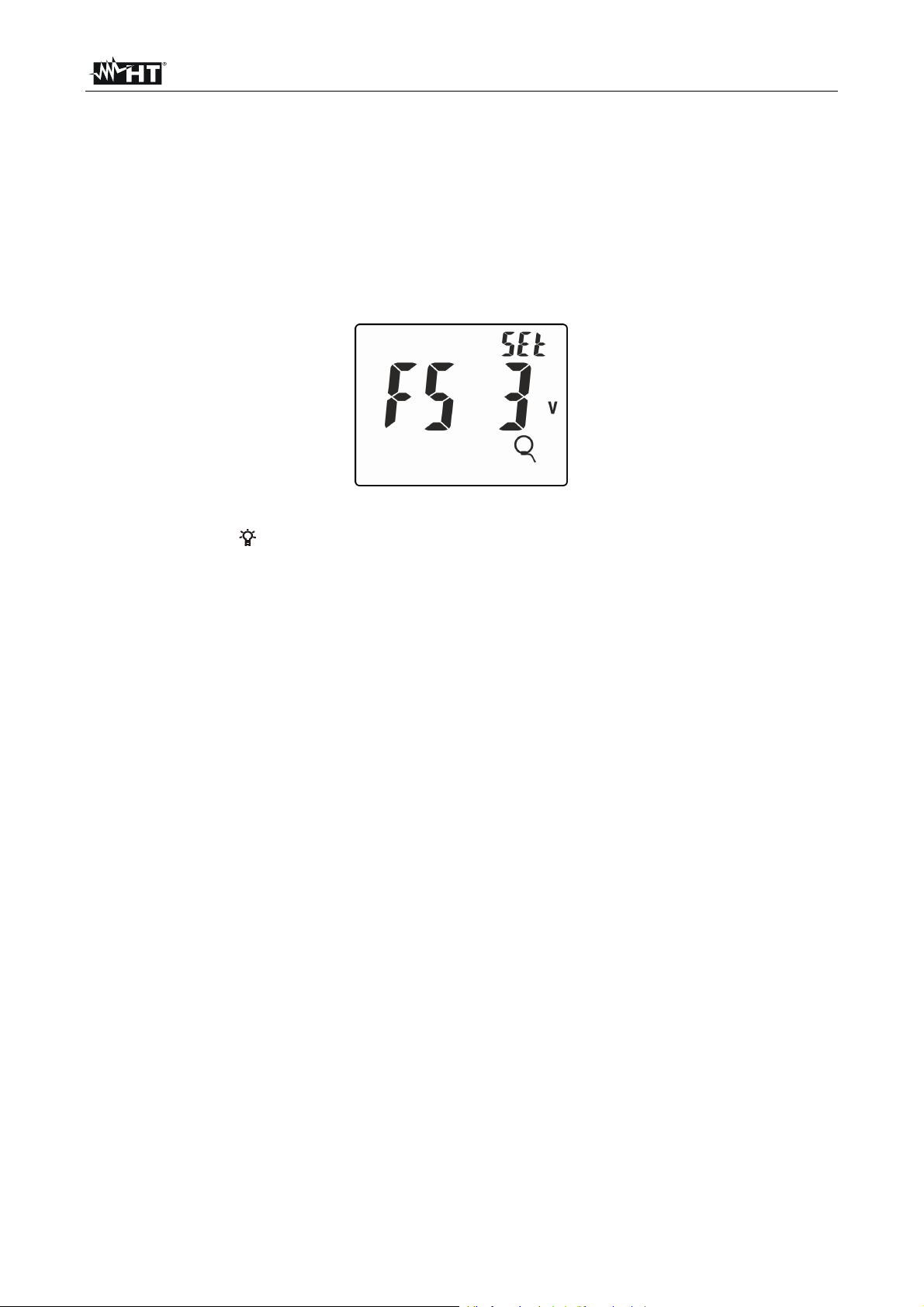
4.2.10. Setting the full scale for flexible clamp transducer
The instrument can be used with a flexible clamp transducer (optional accessory). For a
correct current measurement, it is necessary to set the full scale of voltage for the clamp
in use (please refer to the transducer’s user manual for the correct full scale value to be
set). Proceed as follows:
1. Switch off the instrument (OFF)
2. Press and hold key MODE/MXMNPK and switch on the instrument by turning the
rotary switch. The following screen appears on the display:
Fig. 5: Setting the full scale for flexible clamp transducer
3. Press keys /
or to set the full scale value of the clamp in use among the options:
3VAC (model F3000U) or 1VAC (other models).
4. Press key GO/HOLD to confirm and go back to measuring screen.
5. Settings are maintained very time the instrument is switched on.
EN - 10
Page 13
NEPTUNE
5. OPERATING INSTRUCTIONS
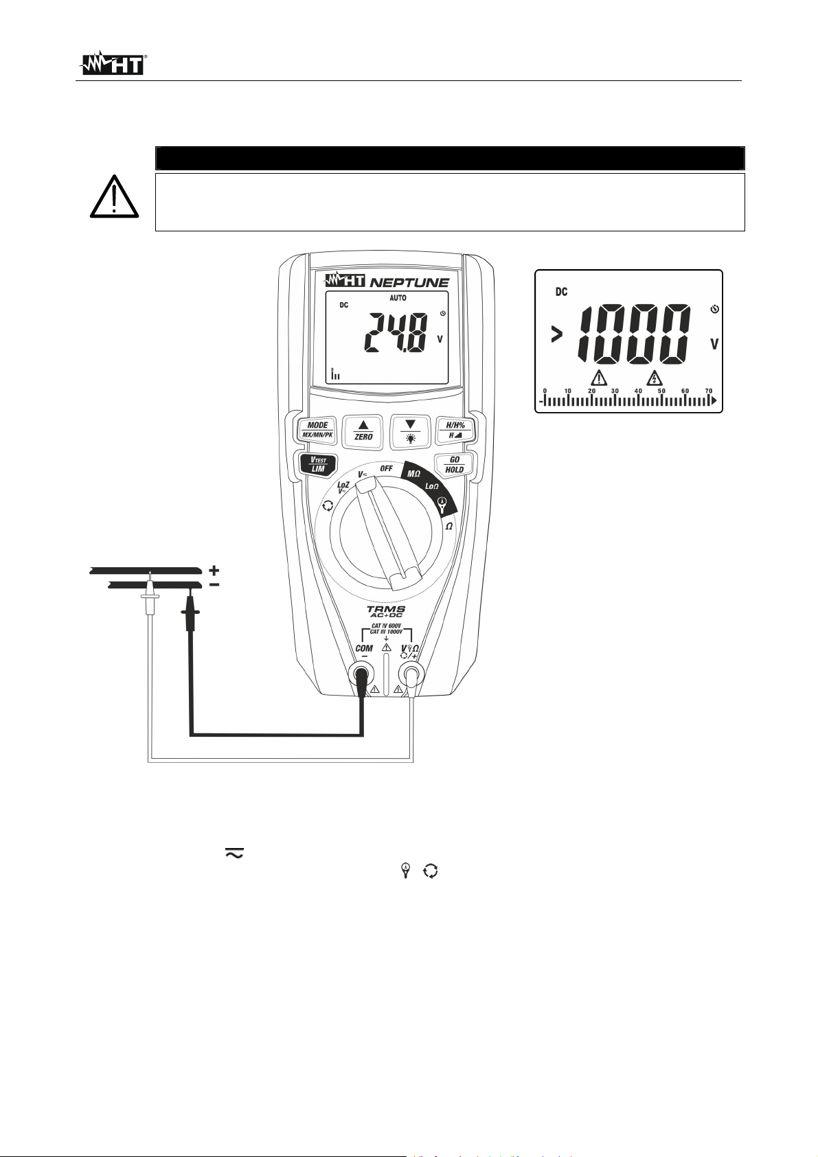
5.1. DC VOLTAGE MEASUREMENT
The maximum input DC voltage is 1000V. Do not measure voltages
exceeding the limits given in this manual. Exceeding voltage limits could
result in electrical shocks to the user and damage to the instrument.
CAUTION
Fig. 6: Use of the instrument for DC voltage measurement
1. Select position V
2. Insert the red cable into input terminal V /+ and the black cable into input terminal
COM.
3. Position the red lead and the black lead respectively in the spots with positive and
negative potential of the circuit to be measured (see Fig. 6). The display shows the
value of voltage.
4. If the display shows the message “>1000V” (see Fig. 6), the maximum measurable
value has been reached.
5. When symbol "-" appears on the instrument’s display, it means that voltage has the
opposite direction with respect to the connection in Fig. 6.
6. To use functions HOLD, MAX/MIN/PK, see § 4.2
EN - 11
Page 14
NEPTUNE
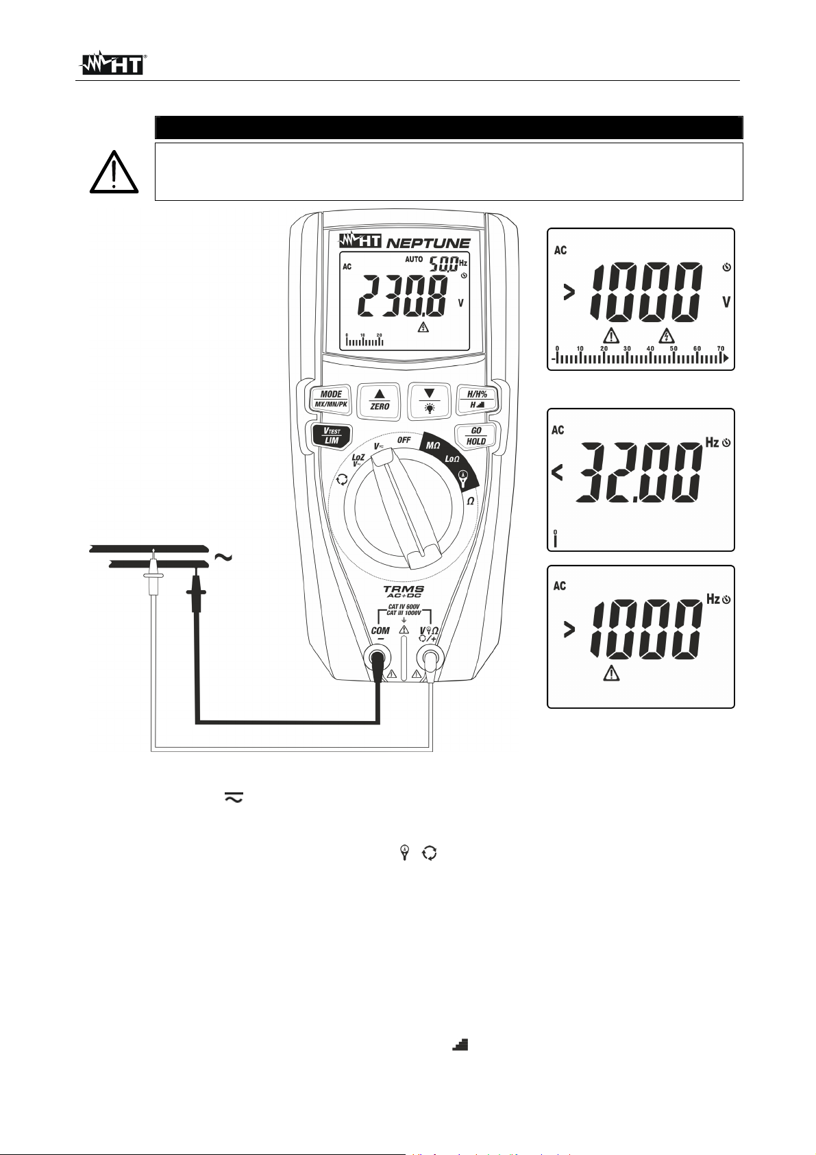
5.2. AC, AC+DC VOLTAGE MEASUREMENT
CAUTION
The maximum input AC voltage is 1000V to earth. Do not measure voltages
exceeding the limits given in this manual. Exceeding voltage limits could
result in electrical shocks to the user and damage to the instrument.
Fig. 7: Use of the instrument for AC voltage measurement
1. Select position V
2. Press the MODE/MXMNPK key until symbol “AC” or “AC+DC” is displayed. The
instrument automatically recognizes AC or DC signals.
3. Insert the red cable into input terminal V /+ and the black cable into input terminal
COM/.
4. Position the red lead and the black lead respectively in the spots of the circuit to be
measured (see Fig. 7). The display shows the value of voltage. On the top of the
display on the right side, the value of voltage frequency is displayed. Press key
MODE/MXMNPK to display the value of frequency with a higher resolution.
5. If the display shows the message “>1000V” (see Fig. 7), the maximum measurable
value has been reached.
6. If the display shows the messages “<32Hz” or “>1000Hz” (see Fig. 7), the value of
frequency is out of the measuring range 32Hz ÷ 1000Hz.
7. To use functions HOLD, MAX/MIN/PK, H/H%/H, see § 4.2
EN - 12
Page 15

NEPTUNE
5.3. AC, DC, AC+DC VOLTAGE WITH LOW IMPEDANCE (LOZ)
CAUTION
The maximum input AC/DC voltage is 1000V to earth. Do not measure
voltages exceeding the limits given in this manual. Exceeding voltage limits
could result in electrical shocks to the user and damage to the instrument.
Fig. 8: Use of the instrument for AC/DC voltage measurement with LoZ function
1. Select position LoZV . The symbols “LoZ” and “DC” appear on the display.
2. Press key MODE/MXMNPK to select
“AC” or “AC+DC” measurement. Anyway, the
instrument automatically recognizes AC or DC signals.
3. Insert the red cable into input terminal V
/+ and the black cable into input terminal
COM/.
4. Position the red lead and the black lead respectively in the positions of the circuit to be
tested (see Fig. 8) for AC voltage measurement or in the positions with a positive or
negative potential of the circuit to be tested (see Fig. 6) for DC voltage measurement.
The display shows the value of voltage. On the top of the display on the right side, the
value of voltage frequency is displayed. Press key MODE/MXMNPK to display the
value of frequency with a higher resolution.
5. If the display shows the messages “<32Hz” or “>1000Hz” (see Fig. 8), the value of
frequency is out of the measuring range 32Hz ÷ 1000Hz.
6. When symbol “-” appears on the instrument's display, it means that voltage has the
opposite direction with respect to the connection in Fig. 6
7. To use functions HOLD, MAX/MIN/PK, H/H%/H, see § 4.2
EN - 13
Page 16

NEPTUNE
5.4. RESISTANCE MEASUREMENT AND CONTINUITY TEST
CAUTION
Before attempting any resistance measurement, cut off power supply from
the circuit to be measured and make sure that all capacitors are discharged,
if present.
Fig. 9: Use of the instrument for resistance measurement and continuity test
1. Select the position.
2. Insert the red cable into input terminal V /+ and the black cable into input terminal
COM.
3. If necessary, short-circuit the measuring leads and press key /ZERO to zero the
resistance of the measuring cables. The symbol “ZERO” appears on the display.
4. Position the test leads in the desired spots of the circuit to be measured (see Fig. 9).
The display shows the value of resistance.
5. If the display shows the message “>2000” (see Fig. 9) the maximum measurable
value has been reached.
6. Press key MODE/MXMNPK to select “ ” measurement, relevant to the continuity test,
and position the test leads in the desired positions of the circuit to be measured.
7. The value of resistance (which is only indicative) is displayed in and the instrument
sounds if the value of resistance is <30.
8. To use functions HOLD, MAX/MIN, H/H%/H , see §. 4.2
EN - 14
Page 17

NEPTUNE
5.5. PHASE SEQUENCE AND PHASE CONCORDANCE WITH 1 TERMINAL
CAUTION
Input AC voltage to carry out this test must be in range 100V ÷ 1000V with
a frequency in range 42.5Hz ÷ 69Hz.
This test can only be performed by touching the metal parts of the
conductors.
Fig. 10: Use of the instrument for phase sequence and phase concordance test
1. Select position
. Message “PH 1” flashes on the display.
2. Insert the red lead into input terminal V /+.
3. Position the red lead onto phase L1 of the three-phase system to be tested (see Fig.
10). The following messages may appear on the display (see Fig. 11) to identify the
presence of a voltage signal with frequency out of range 42.5Hz ÷ 69Hz. In these
conditions, the instrument does not perform the test.
Fig. 11: Signal of voltage with wrong frequency
EN - 15
Page 18

NEPTUNE
4. In conditions of correct voltage and frequency, the instrument shows message “HOLD”,
symbols and “PH1” and the buzzer sounds continuously, waiting for a stable voltage
value on phase L1 to be detected (see Fig. 12 – left side).
Fig. 12: Detecting phase L1 and waiting for phase L2
5. Do not remove the lead from phase L1 until message “PH 2” appears flashing on the
display (see Fig. 12 – right side)
Fig. 13: Detecting phase L1 and waiting for phase L2
6. Position the red lead onto phase L2 of the three-phase system to be tested (see Fig.
10). In case passage between phase L1 and phase L2 takes more than 10s, the
instrument shows message “t.out” on the display (see Fig. 13 – left side). In conditions
of correct voltage and frequency, the instrument shows message “HOLD”, symbols
“PH2” and the buzzer sounds continuously, waiting for a stable voltage value on
and
phase L2 to be detected (see Fig. 13
– right side).
7. Upon detection of a stable voltage value on phase L2, the instrument automatically
shows message “1.2.3.” (test OK) or message “2.1.3” (test NOT OK) as shown in Fig.
14
Fig. 14: Results of phase sequence and phase concordance test
8. In case it is necessary to check phase concordance between two parallel three-phase
systems, after detection of phase L1 of the first system, position the lead on phase L1
of the second system. The correct final result is message “1.1-” (see Fig. 14 – right side)
EN - 16
Page 19

NEPTUNE
5.6. MEASUREMENT OF INSULATION RESISTANCE
This function is performed in compliance with standard IEC/EN61557-2 and allows
measuring insulation resistance in electric installations and industrial applications where it
is necessary to carry out duration tests (see § 9.2). The following operating modes are
available:
AUTO the test continues until a stable result is obtained (minimum duration 3s, max
15s) or until key GO/HOLD is pressed. Recommended mode
TMR the test is carried out in a continuous mode for the duration (timer) set, among
the values: 15s, 30s, 1min, 5min, 10min
PI the test is carried out in a continuous mode for the duration (timer) set, among
the values: 1min,10min. If the set time is 1min, the instrument will display the
value of parameter DAR (Dielectric Absorption Ratio) (see § 9.2.2).
1min,10min. If the set time is 10min, the instrument will display the value of
AUTO mode
parameter PI (Polarization Index) (see § 9.2.1).
CAUTION
Check that the circuit being tested is not live and that all possible loads
normally connected to it are disconnected before carrying out insulation
measurement.
We recommend holding the alligator clip respecting the safety area created
by the hand protection.
Fig. 15: Use of the instrument for insulation resistance measurement in AUTO mode
1. Select position M
2. Press key MODE/MXMNPK and select option “AUTO”
3. Press key VTEST/LIM to set the test voltage choosing among the values: 50V, 100V,
250V, 500V, 1000VDC. Please note the value in the top part of the display.
4. Press and hold key VTEST/LIM (>2s) to set the minimum limit threshold for
measurement. The symbol “Set” flashes on the display.
EN - 17
Page 20

NEPTUNE
5. Press keys / or /ZERO to select the value among the options: 0.10M,
0.230M, 0.50M, 1.00M, 100M, no. Option “no” indicates that no threshold was
set (see Fig. 16).
Fig. 16: Setting the limit threshold for insulation measurement
6. Press key GO/HOLD to confirm and quit the setting section. The buzzer gives a short
continuous sound.
7. Insert the red lead into input terminal V /+ and the black lead into input terminal
COM/ and possible alligator clips, and connect the instrument to the system to be
tested (see Fig. 15).
8. Press key GO/HOLD to activate the test. The following screen may appear on the
display to signal the presence of a voltage >10V found on the input terminals,
preventing the test to be carried out.
Fig. 17: Presence of voltage on the input terminals
9. In case no anomalous conditions are found, the instrument performs the test until key
GO/HOLD is pressed and held. Otherwise, the test has a duration of approx. 3s if the
key is immediately released, symbol flashes on the display and the buzzer gives out
an intermittent sound. At the end of the test, the following screens appear on the
display.
Fig. 18: Results of insulation measurement in AUTO mode
10. In the screen in Fig. 18
“>999” indicates the out-of-range condition) with positive result “OK” (value higher than
– left side, the value of insulation resistance is present (symbol
the set threshold). In the screen in Fig. 18 – right side, the value of insulation resistance
is present with negative result “NOT OK” (value lower than the set threshold).
11. Press keys / or /ZERO to display the real applied voltage.
EN - 18
Page 21

NEPTUNE
TMR mode
CAUTION
Check that the circuit being tested is not live and that all possible loads
normally connected to it are disconnected before carrying out insulation
measurement.
We recommend holding the alligator clip respecting the safety area created
by the hand protection.
Fig. 19: Use of the instrument for insulation resistance measurement in TMR mode
1. Select position M
2. Press key MODE/MXMNPK and select option
3. Press key V
TEST/LIM to set the test voltage choosing among the values: 50V, 100V,
“TMR”
250V, 500V, 1000VDC. Please note the value in the top part of the display.
4. Press and hold key V
TEST/LIM (>2s) to set the minimum limit threshold for
measurement. The symbol “Set” flashes on the display. Press keys / or /ZERO
to select the value among the options: 0.10M, 0.230M, 0.50M, 1.00M, 100M,
no. Option “no” indicates that no threshold was set (see Fig. 16).
5. Press keys / or /ZERO to select the measuring time (timer) choosing among
the options: 15s, 30s, 1min, 5min, 10min. Please note the value in the top part of the
display on the right (see Fig. 20).
Fig. 20: Setting the measuring time in TMR mode
EN - 19
Page 22

NEPTUNE
6. Insert the red lead into input terminal V /+ and the black lead into input terminal
COM/ and possible alligator clips, and connect the instrument to the system to be
tested (see Fig. 19).
7. Press key GO/HOLD to activate the test. The screen in Fig. 17 may appear on the
display to signal the presence of a voltage >10V found on the input terminals,
preventing the test to be carried out.
8. In case no anomalous conditions are found, the instrument performs the test in a
continuous mode with a countdown of time (until time “0:00”) for the entire duration of
the set timer, symbol flashes on the display and the buzzer gives out an intermittent
sound. At the end of the test, the following screens appear on the display.
Fig. 21: Results of insulation measurement in TMR mode
9. In the screen in Fig. 21 – left side, the value of insulation resistance is present (symbol
“>1999” indicates the out-of-range condition) at the end of measurement with positive
result “OK” (value higher than the set threshold). In the screen in Fig. 21 – right side, the
value of insulation resistance is present at the end of measurement with negative result
“NOT OK” (value lower than the set threshold).
10. Press keys / or /ZERO to display the real applied voltage.
PI mode
The PI mode is used to carry out diagnostic duration tests on materials (appliances,
electric cables, etc.) in order to evaluate the quality of insulation. The purpose is the
evaluation of the following coefficients:
Polarization Index (PI) defined as:
Riso
PI
Riso
min)10(
min)1(
Dielectric Absorption Ratio (DAR) defined as:
DAR
See § 9.2.1 and § 9.2.2 for further details.
Riso
min)1(
)30(
sRiso
CAUTION
Check that the circuit being tested is not live and that all possible loads
normally connected to it are disconnected before carrying out insulation
measurement.
We recommend holding the alligator clip respecting the safety area created
by the hand protection.
EN - 20
Page 23

NEPTUNE
Fig. 22: Use of the instrument for insulation resistance measurement in PI mode
1. Select position M
2. Press key MODE/MXMNPK and select option “PI”
3. Press key VTEST/LIM to set the test voltage choosing among the values: 50V, 100V,
250V, 500V, 1000VDC. Please note the value in the top part of the display.
4. Press and hold key VTEST/LIM (>2s) to set the minimum limit threshold for
measurement. The symbol “Set” flashes on the display. Press keys / or /ZERO
to select the value among the options: 0.10M, 0.230M, 0.50M, 1.00M, 100M,
no. Option “no” indicates that no threshold was set (see Fig. 16).
5. Press keys / or /ZERO to select the measuring time (timer) choosing among
the options: 1min (for DAR measurement) or 10min (for PI measurement). Please note
the value in the top part of the display on the right (see Fig. 20).
6. Insert the red lead into input terminal V
COM/
and possible alligator clips, and connect the instrument to the appliance to be
/+ and the black lead into input terminal
tested (see Fig. 22).
7. Press key GO/HOLD to activate the test. The screen in Fig. 17 may appear on the
display to signal the presence of a voltage >10V found on the input terminals,
preventing the test to be carried out.
8. In case no anomalous conditions are found, the instrument performs the test in a
continuous mode with a countdown of time (until time “0:00”) for the entire duration of
the set timer, symbol flashes on the display and the buzzer gives out an intermittent
sound. At the end of the test, the following screens appear on the display.
Fig. 23: Results of insulation measurement in PI mode
EN - 21
Page 24

NEPTUNE
9. In the screen in Fig. 23 – left side, the value of insulation resistance is present at the
end of measurement with positive result “OK” (value higher than the set threshold). In
the screen in Fig. 23 – right side, the value of insulation resistance is present at the end
of measurement with negative result “NOT OK” (value lower than the set threshold).
10. Press keys / or /ZERO to display the real applied voltage, the value of
parameter PI or the value of parameter DAR (see Fig. 24).
Fig. 24: Results of PI and DAR measurements
EN - 22
Page 25

NEPTUNE
5.7. CONTINUITY OF PROTECTIVE CONDUCTORS WITH 200MA
This function is performed in compliance with standard IEC/EN61557-4 and allows
measuring the continuity of protective and equipotential conductors. The following
operating modes are available:
AUTO the test is activated by pressing key GO/HOLD and the result is immediately
displayed after comparing it with the set maximum threshold value.
Recommended mode
TMR the test is carried out in a continuous mode for the duration (timer) set in range
1s ÷ 30s, and the result is shown on the display after comparing it with the set
maximum threshold value.
ZERO compensation of the resistance of the cables used for measurement. The
instrument automatically subtracts the value of cable resistance from the
measured resistance value. It is therefore necessary that this value is measured
(by means of the ZERO function) each time the test cables are changed or
extended.
AUTO mode
CAUTION
Check that the circuit being tested is not live and that all possible loads
normally connected to it are disconnected before carrying out insulation
measurement.
The continuity test is performed by supplying a current higher than 200mA for
resistances not higher than 5 (including the resistance of the measuring
cables). For higher resistance values, the instrument carries out the test with
a current lower than 200mA.
Fig. 25: Use of the instrument for continuity test in AUTO mode
EN - 23
Page 26

NEPTUNE
1. Select position Lo
2. Press key MODE/MXMNPK and select option “AUTO”
3. Press and hold key VTEST/LIM (>2s) to set the maximum limit threshold for
measurement. The symbol “Set” flashes on the display.
4. Press keys / or /ZERO to select the value in the range: 0.05 ÷ 9.99 (see Fig.
26).
Fig. 26: Setting the limit threshold for continuity test
5. Press key GO/HOLD to confirm and quit the setting section. The buzzer gives a short
continuous sound.
6. If necessary, compensate the test cables (see § 5.7.1).
7. Insert the red lead into input terminal V /+ and the black lead into input terminal
COM/, and connect the instrument to the system to be tested (see Fig. 25).
8. Press key GO/HOLD to activate the test. The following screen may appear on the
display to signal the presence of a voltage >10V found on the input terminals,
preventing the test to be carried out.
Fig. 27: Presence of voltage on the input terminals
9. In case no anomalous conditions are present, the instrument carries out the test and
symbol
the display.
flashes on the display. At the end of the test, the following screens appear on
Fig. 28: Results of continuity test in AUTO mode
10. In the screen in Fig. 28 – left side, a positive test result “OK” is shown (value lower than
the set threshold and test current >200mA). In the screen in Fig. 28
– middle, a
negative test result “NOT OK” is shown (value higher than the set threshold and test
current <200mA). In the screen in Fig. 28 – right side, a negative test result “NOT OK” is
shown, corresponding to the out-of-range condition (symbol “>200.0”).
EN - 24
Page 27

NEPTUNE
TMR mode
CAUTION
Check that the circuit being tested is not live and that all possible loads
normally connected to it are disconnected before carrying out insulation
measurement.
The continuity test is performed by supplying a current higher than 200mA for
resistances not higher than 5
(including the resistance of the measuring
cables). For higher resistance values, the instrument carries out the test with
a current lower than 200mA.
Fig. 29: Use of the instrument for continuity test in TMR mode
1. Select position Lo
2. Press key MODE/MXMNPK and select option “TMR”
3. Press and hold key VTEST/LIM (>2s) to set the maximum limit threshold for
measurement. The symbol “Set” flashes on the display.
4. Press keys / or /ZERO to select the value in the range: 0.05 ÷ 9.99 (see Fig.
26).
5. Press keys / or /ZERO to select the measuring time (timer) in range: 1s ÷ 30s.
Please note the value in the top part of the display on the right (see Fig. 30).
Fig. 30: Setting the measuring time in TMR mode
EN - 25
Page 28

NEPTUNE
6. If necessary, compensate the test cables (see § 5.7.1).
7. Insert the red lead into input terminal V /+ and the black lead into input terminal
COM/, and connect the instrument to the system to be tested (see Fig. 29).
8. Press key GO/HOLD to activate the test. The screen in Fig. 27 may appear on the
display to signal the presence of a voltage >10V found on the input terminals,
preventing the test to be carried out.
9. In case no anomalous conditions are found, the instrument performs the test in a
continuous mode with a countdown of time (until time “0”) for the entire duration of the
set timer, and symbol flashes on the display. At the end of the test, the following
screens appear on the display:
Fig. 31: Results of continuity test in TMR mode
10. In the screen in Fig. 31 – left side, a positive test result “OK” is shown (value lower than
the set threshold and test current >200mA). In the screen in Fig. 31 – middle, a
negative test result “NOT OK” is shown (value higher than the set threshold and test
current <200mA). In the screen in Fig. 31 – right side, a negative test result “NOT OK” is
shown, corresponding to the out-of-range condition (symbol “>200.0”).
EN - 26
Page 29

NEPTUNE
5.7.1. Function ZERO – Zeroing of test cable resistance
In every operating mode (AUTO, TMR) it is possible to zero the resistance of the test
cables before carrying out continuity tests. This operation is recommended upon the first
use of the provided test cables and in case different cables must be used (e.g. cable
extensions). The operation is only possible for test cable resistance <5.00.
1. Select position Lo
2. Insert the test cables into input terminal V /+ and COM/, connect the alligator clips
and shot-circuit the cable ends between each other (see Fig. 32).
Fig. 32: Connection of the cables in compensation function
3. Press and hold (>2s) key /ZERO. The instrument starts the compensation procedure
of cable resistance, immediately followed by the verification of the compensated value.
The following screens are displayed in a quick sequence:
Fig. 33: Results of a correctly performed zeroing
4. The instrument performs the first measurement, detecting the resistance of the test
cables (see Fig. 33 – left side). If the compensated value (ZERO) is ≤5.00, the
instrument keeps it saved and carries out the following test by performing a second
EN - 27
Page 30

NEPTUNE
measurement and comparing this new value to the compensated one. If the difference
between the values is ≤0.01, calibration is confirmed and the message “OK” is
displayed (see Fig. 33 – middle). Subsequently, the instrument goes back to the
measuring screen with the message “ZERO” displayed to indicate that cable
compensation is present.
5. In case the first measurement detects a resistance of test cables >5.00, the
instrument shows the following screens in a quick sequence:
Fig. 34: Results of zeroing not correctly performed
6. Messages “>5.00” and “NOT OK” are initially shown on the display (see Fig. 34 – left
side). Subsequently, message “CLr” is shown, to indicate that calibration has been
cancelled (see Fig. 34 – middle) and the message “ZERO” is not shown in the
measuring screen (see Fig. 34 – right side).
7. To zero a cable calibration in the instrument, carry out the procedure with open input
terminals V /+ and COM/ and press and hold (>2s) key /ZERO. The following
screens are displayed in a quick sequence:
Fig. 35: Zeroing calibration
EN - 28
Page 31

NEPTUNE
5.8. MEASUREMENT OF DC, AC, AC+DC, INRUSH CURRENT WITH CLAMP
TRANSDUCERS
CAUTION
Maximum measurable current in this function is 3000A AC or 1000A DC.
Do not measure currents exceeding the limits given in this manual.
The instrument carries out the measurement both with flexible clamp
transducers (optional accessories) and with other standard clamp
transducers in the HT family (optional accessories). With transducers
having an Hypertac output connector, the optional adapter NOCANBA is
necessary to obtain the connection.
Fig. 36: Use of the instrument for current measurement with clamp transducer
1. Select the position.
2. Press key MODE/MXMNPK to select the type of clamp transducer among the options:
“ ” (flexible clamp transducer – only AC) or “ ” (standard clamp transducer – AC or DC).
3. Press keys / or and, on the instrument, select the same range set on the
clamp, among the options: 30A, 300A, 3000A (AC current measurement with flexible
clamp) or: 1A, 10A, 30A, 40A, 100A, 200A, 300A, 400A, 1000A, 2000A, 3000A for
AC, DC, AC+DC current measurement with standard clamp).
4. For flexible clamp transducers, set the relevant full scale value of voltage (see §
4.2.10).
5. Press key GO/HOLD to confirm settings.
EN - 29
Page 32

NEPTUNE
6. For standard clamp transducers, press key MODE/MXMNPK to select “AC”, “DC” or
“AC+DC” measurement. Anyway, the instrument automatically recognizes AC or DC
quantities.
7. Insert the red cable into input terminal V /+ and the black cable into input terminal
COM/.. For standard transducers with Hypertac connector, use optional adapter
NOCANBA. For information on the use of clap transducers, please refer to the relevant
user manual.
8. Insert the cable into the center of the jaws (see Fig. 36). The value of current is shown
in Fig. 37
Fig. 37: Result of AC current measurement with standard and flexible clamp
9. Press key MODE/MXMNPK to display the value of frequency of AC current with a high
resolution (see Fig. 38).
Fig. 38: Result of frequency measurement with standard and flexible clamp
10. The following screens may be shown on the display:
Fig. 39: Anomalous situations on current measurement with clamp transducers
11. Message
full scale (300A in case of Fig. 39). If the display shows the messages
“>1000Hz”, the measured value of current frequency is out of the measuring range
“>300A” indicates that the value of current measured is higher than the set
“<32.00Hz” or
32Hz ÷ 1000Hz.
12. To use functions HOLD, MAX/MIN/PK, H/H%/H, see § 4.2
EN - 30
Page 33

NEPTUNE
Inrush current measurement (DIRC)
CAUTION
Maximum measurable current in this function is 3000A AC or 1000A DC.
Do not measure currents exceeding the limits given in this manual.
The instrument carries out the measurement both with flexible clamp
transducers (optional accessories) and with other standard clamp
transducers in the HT family (optional accessories). For inrush currents
containing a high DC component, the use of AC/DC clamps is
recommended. With transducers having an Hypertac output connector,
the optional adapter NOCANBA is necessary to obtain the connection.
1. Select the position.
2. Press key MODE/MXMNPK to select the type of clamp transducer among the options:
“ ” (flexible clamp transducer – only AC) or “ ” (standard clamp transducer – AC or DC).
3. Press the keys / or and, on the instrument, select the same range set on the
clamp, among the options: 30A, 300A, 3000A (AC current measurement with flexible
clamp) or: 1A, 10A, 30A, 40A, 100A, 200A, 300A, 400A, 1000A, 2000A, 3000A for AC
or AC+DC current measurement with standard clamp.
4. For flexible clamp transducers, set the relevant full scale value (see § 4.2.10).
5. Press key GO/HOLD to confirm settings.
6. Press key MODE/MXMNPK to select “IRC” measurement. The following screens are
shown on the display according to the type of clamp used:
Fig. 40: Initial screens of inrush current measurement
7. Connect the clamps to the system to be tested as indicated in § 5.8
8. Press key GO/STOP to activate the function. The instrument waits for the event to be
recognized (measured value higher than the fixed trigger threshold equal to 1%FS
clamp: e.g. 30A with FS = 3000A) and shows symbol
“ ” on the display (see Fig. 41 –
left side).
Fig. 41: Recognition of inrush current event
EN - 31
Page 34

NEPTUNE
9. Upon recognition of the event, measurement stops automatically and the instrument
shows, in its main display, the Max RMS value calculated according to the evaluation
time of 100ms (default) indicated on the secondary display (see Fig. 41 – right side).
10. Press keys / or to select the display of the following parameters:
Peak value “Pk” calculated in 1ms (see Fig. 42 – left side)
Max RMS value calculated in 16.7ms
Max RMS value calculated in 20ms
Max RMS value calculated in 50ms
Max RMS value calculated in 100ms
Max RMS value calculated in 150ms
Max RMS value calculated in 175ms
Max RMS value calculated in 200ms
Fig. 42: Examples of display of inrush current
11. If the measured current is higher than the set FS of the clamp, a message like the one
in Fig. 42 – right side (relevant to FS = 3000A) is shown on the display.
12. Press key GO/HOLD again to start a new measurement or turn the rotary switch to quit
the function.
EN - 32
Page 35

NEPTUNE
6. MAINTENANCE
CAUTION
Only expert and trained technicians should perform maintenance
operations. Before carrying out maintenance operations, disconnect all
cables from the input terminals.
Do not use the instrument in environments with high humidity levels or
high temperatures. Do not expose to direct sunlight.
Always switch off the instrument after use. In case the instrument is not to
be used for a long time, remove the battery to avoid liquid leaks that could
damage the instrument’s internal circuits.
6.1. BATTERY REPLACEMENT
When the LCD display shows symbol “ ” and the indication “bAtt” (see Fig. 43), batteries
need to be replaced, operating as follows:
Fig. 43: Screen with low battery indication
1. Position the rotary switch to OFF and remove the cables from the input terminals.
2. Turn the fastening screw of the battery compartment cover from position “ ” to position
“ ” and remove it.
3. Remove the battery and insert a new battery of the same type (see § 7.1.1), respecting
the indicated polarity.
4. Restore the battery compartment cover into place and turn the fastening screw from
position
“ ” to position “ ”.
5. Do not scatter old batteries into the environment. Use the relevant containers for
disposal.
6.2. CLEANING THE INSTRUMENT
Use a soft and dry cloth to clean the instrument. Never use wet cloths, solvents, water, etc.
6.3. END OF LIFE
WARNING: the symbol on the instrument indicates that the appliance and its
accessories must be collected separately and correctly disposed of.
EN - 33
Page 36

NEPTUNE
7. TECHNICAL SPECIFICATIONS
7.1. TECHNICAL CHARACTERISTICS
Accuracy calculated as [%reading + (no. digits*resolution)] at 23°C 5°C <80%RH.
DC Voltage (Autorange)
Range
[V]
0.0 999.9
AC, AC+DC, Loz TRMS Voltage (Autorange)
Range
[V]
0.5 999.9
Input impedance function VAC: 5M,
Input impedance function LoZ: 3.5k for 10s (@ 110V/50Hz), 4.5s (@ 230V/50Hz), 1s (@ 400V/50Hz). For higher
voltage values, input impedance becomes higher than 10k. WARNING: do not leave the instrument connected for
more than 1min.
Automatic selection DC mode, Max crest factor: 1.5
Current and Voltage frequency (Autorange)
Range [Hz] Resolution [Hz] Accuracy
32.00 99.99
100.0 999.9
Voltage range: 0.5V ÷ 999.9V, Current field: 0.5A ÷ 3000A (Flexible clamp F3000U), 1mV ÷ 1000mV (STD clamp)
AC TRMS Current (Flexible clamp F3000U) – (Autorange)
Range [mV] Resolution [mV] Accuracy (*)
1 3000
(*) For frequency >100Hz accuracy is: (1.5%reading + 5digits)
Max crest factor: 3 ; Frequency bandwidth: 1kHz ; Current zeroed for value <1%FS [A]
AC TRMS Current (flexible clamp FS 1V) and DC, AC, AC+DC (STD clamp) – (Autorange)
Range [mV] Resolution [mV] Accuracy (*)
1 1000
(*) For frequency >100Hz accuracy is: (1.5%reading + 5digits)
Max crest factor: Frequency bandwidth: 1kHz;
Current zeroed for value <1%FS [A] (Flex clamp 1V), Current zeroed for value <1%FS [A] (STD clamp)
AC TRMS inrush current (Flexible clamp F3000U)
Range [mV] Resolution [mV] Accuracy (*)
1 3000
(*) Accuracy declared for frequency: DC, 42.5 ÷ 69Hz
Max crest factor: 3, Sampling frequency: 4kHz
Detection threshold: 1%FS [A] fixed
Response time: 1ms (Peak), 16.7ms, 20ms, 50ms, 100ms, 150ms, 175ms, 200ms (max RMS)
AC TRMS inrush current (Flexible clamp 1V) and DC, AC, AC+DC TRMS (STD clamp)
Range [mV] Resolution [mV] Accuracy (*)
1 1000
(*) Accuracy declared for frequency: DC, 42.5 ÷ 69Hz
Max crest factor: 3, Sampling frequency: 4kHz
Detection threshold: 1%FS [A] fixed
Response time: 1ms (Peak), 16.7ms, 20ms, 50ms, 100ms, 150ms, 175ms, 200ms (max RMS)
Resistance and continuity test (Autorange)
Range [] Resolution []
0.0 199.9
200 1999
Resolution
[V]
0.1
Resolution
[V]
(0.5%rdg + 2digits) 5M
Frequency Accuracy Overload protection
0.1 32Hz ÷ 1kHz
Accuracy
0.01
0.1
0.1
1
Input
impedance
(0.5%reading + 2digits)
1
1
1
1
Accuracy Buzzer
(1.0%reading +
5digits)
Overload protection
1000VDC/ACrms
1000VDC/ACrms
(0.1%rdg +1digit)
(0.5%rdg + 2digits)
(0.5%rdg + 2digits)
(2%reading + 2digits)
(2%reading + 2digits)
<30
EN - 34
Page 37

NEPTUNE
Harmonic voltage and current (Autorange)
Harmonic order
DC
1 25 (5.0rdg+10digits)
Fundamental
frequency
42.5Hz 69Hz
Resolution
0.1V / 0.1A /0.1%
THD% 0.1%
Accuracy of harmonic amplitudes expressed in % is evaluated considering the accuracy of parameters’ ratio
(*) Harmonic voltages will be zeroed under the following conditions:
1st harmonic: value <0.5V
DC, 2nd to 25th harmonic: harmonic value <0.5% fundamental value or value <0.5V
(*) Harmonic currents will be zeroed under the following conditions
1st harmonic: value <1%FS[A]
DC, 2nd to 25th harmonic: harmonic value <0.5% fundamental value or value <1%FS[A].
Accuracy (*)
(non-zeroed values)
(5.0rdg+20digits)
(10.0rdg+10digits)
Insulation resistance (M)
Test voltage [V]
50
100
250
500
1000
Open-circuit voltage: rated test voltage (-0% ÷ 10%)
Short-circuit current: < 6mA (peak) with each rated test voltage
Rated test current: >1mA with 1k x Vnom (50V, 100V, 250V, 1000V), >2.2mA with 230k @ 500V
Input protection: error message for voltage > 10V
Range [M] Resolution [M]
0.01 9.99
10.0 99.9
0.01 9.99
10.0 99.9
100.0 199.9 (5.0read. + 2digits)
0.01 9.99
10.0 99.9
100 499
0.01 9.99
10.0 199.9
200 499
500 999 (5.0read. + 2digits)
0.01 9.99
10.0 199.9
200 999
1000 1999 (5.0read. + 2digits)
0.01
0.1
0.01
0.1
0.01
0.1
1
0.01
0.1
1
0.01
0.1
1
Accuracy
(5.0read. + 2digits)
(2.0read. + 2digits)
(2.0read. + 2digits)
(5.0read. + 2digits)
(2.0read. + 2digits)
(2.0read. + 2digits)
Continuity of protective conductors (Lo)
Range [] Resolution []
0.00 9.99
10.0 199.9
Test current: >200mA DC up to 5 (cables included), resolution 1mA, accuracy (5.0%reading + 5digits).
Open-circuit voltage: 4 < V
Input protection: error message for voltage > 10V
< 12V
0
0.01
0.1
(2.0%reading + 2digits)
Accuracy
Phase sequence with 1 terminal (*)
Voltage range L-N, L-PE [V] Frequency range
100.0 999.9
(*) Measurement possible by direct contact on the metallic parts of the conductors (not on the insulating sheath)
42.5 ÷ 69Hz
EN - 35
Page 38

NEPTUNE
Reference guidelines
Instrument safety: IEC/EN61010-1,IEC/EN61010-2-030,
IEC/EN61010-2-033
EMC: IEC/EN 61326-1
M test: IEC/EN 61557-2
Lo test: IEC/EN 61557-4
Phase sequence: IEC/EN 61557-7
Insulation: double insulation
Pollution level: 2
Measurement category: CAT IV 600V, CAT III 1000V to earth and
between inputs
7.1.1. General characteristics
Mechanical characteristics
Size (L x W x H): 175 x 85 x 55mm (7 x 3 x 2in)
Weight (batteries included): 420g (15ounces)
Mechanical protection: IP40
Power supply
Battery type: 4x1.5V batteries type AAA IEC LR03
Low battery indication: symbol “” ” on the display
Battery life: V, A, , approx. 132h (backlight OFF)
V, A, , approx. 68h (backlight ON)
M (@500V) approx. 400 tests (backlight
OFF).
Lo approx. 2000 tests (backlight OFF).
Auto Power Off: after 15 minutes’ idling (can be disabled)
Display
Type of display: 4 dgt LCD, max 9999 dots, decimal sign, point
backlight and bargraph, indication of polarity
Sampling frequency: 2 times/s
Conversion: RMS
7.2. ENVIRONMENTAL CONDITIONS FOR USE
Reference temperature: 23°C
5°C (73°F ± 41°F)
Operating temperature: 5°C ÷ 40°C (41°F ÷ 104°F)
Allowable relative humidity: <80%RH
Storage temperature: -20°C ÷ 60°C (-4°F ÷ 140°F)
Storage humidity: <80%RH
Max operating altitude: 2000m (6562ft)
This instrument satisfies the requirements of Low Voltage Directive 2014/35/EU
(LVD) and of EMC Directive 2014/30/EU.
This instrument satisfies the requirements of European Directive 2011/65/EU (RoHS)
and 2012/19/EU (WEEE).
7.3. ACCESSORIES
See the attached packing list.
EN - 36
Page 39

NEPTUNE
8. ASSISTANCE
8.1. WARRANTY CONDITIONS
This instrument is warranted against any material or manufacturing defect, in compliance
with the general sales conditions. During the warranty period, defective parts may be
replaced. However, the manufacturer reserves the right to repair or replace the product.
Should the instrument be returned to the After-sales Service or to a Dealer, transport will
be at the Customer's charge. However, shipment will be agreed in advance. A report will
always be enclosed to a shipment, stating the reasons for the product's return. Only use
original packaging for shipment. Any damage due to the use of non-original packaging
material will be charged to the Customer. The manufacturer declines any responsibility for
injury to people or damage to property.
The warranty shall not apply in the following cases:
Repair and/or replacement of accessories and battery (not covered by warranty).
Repairs that may become necessary as a consequence of an incorrect use of the
instrument or due to its use together with non-compatible appliances.
Repairs that may become necessary as a consequence of improper packaging.
Repairs which may become necessary as a consequence of interventions performed
by unauthorized personnel.
Modifications to the instrument performed without the manufacturer's explicit
authorization.
Use not provided for in the instrument's specifications or in the instruction manual.
The content of this manual cannot be reproduced in any form without the manufacturer's
authorization.
Our products are patented and our trademarks are registered. The manufacturer
reserves the right to make changes in the specifications and prices if this is due to
improvements in technology.
8.2. ASSISTANCE
If the instrument does not operate properly, before contacting the After-sales Service,
please check the conditions of battery and cables and replace them, if necessary. Should
the instrument still operate improperly, check that the product is operated according to the
instructions given in this manual. Should the instrument be returned to the After-sales
Service or to a Dealer, transport will be at the Customer's charge. However, shipment will
be agreed in advance. A report will always be enclosed to a shipment, stating the reasons
for the product's return. Only use original packaging for shipment; any damage due to the
use of non-original packaging material will be charged to the Customer.
EN - 37
Page 40

NEPTUNE
9. THEORETICAL APPENDIXES
9.1. CONTINUITY OF PROTECTIVE CONDUCTORS
Purpose of the test
Checking the continuity of:
Protective conductors (PE), main equalizing potential conductors (EQP), secondary
equalizing potential conductors (EQS) in TT and TN-S systems.
Neutral conductors having functions of protective conductors (PEN) in TN-C systems.
This test is to be preceded by a visual check verifying the existence of yellow-green
protective and equalizing potential conductors as well as compliance of the sections used
with the standards’ requirements.
Parts of the system to be checked
Connect one of the test leads to the
protective conductor of the socket
and the other to the equalizing
potential node of the earth
installation.
Connect one of the test leads to the
external mass (in this case the water
pipe) and the other to the earth
installation using for example the
protective conductor of the closest
socket.
Fig. 44: Examples of continuity measures of conductors
Check continuity between:
Earth poles of all the plug sockets and earth collector or node.
Earth terminals of class I appliances (boilers, etc.) and earth collector or node.
Main external masses (water tubes, gas tubes, etc.) and earth terminal or node.
Additional external masses between each other and to earth terminal.
Allowable values
The standards do not require the measurement of continuity resistance and the
comparison of the results with limit values. The standards simply require that the
instrument in use warns the operator if the test was not carried out with a current of at
least 200mA and an open-circuit voltage ranging from 4 to 24V. The resistance values
may be calculated according to the sections and lengths of the conductors being tested. In
general, if the instrument detects values of some ohms, the test may be considered as
successful.
EN - 38
Page 41

NEPTUNE
9.2. MEASUREMENT OF INSULATION RESISTANCE
Purpose of the test
Check that the insulation resistance of the installation complies with the requirements of
the applicable standard. This test has to be performed with the circuit being tested not
powered and with the possible loads it supplies disconnected.
Description Test voltage [V]
SELV or PELV systems
Systems up to 500V (private inst.)
Systems over 500V
250VDC
500VDC
1000VDC
Minimum allowable value [M]
> 0.250 M
> 1.00 M
> 1.00 M
Table 1: Most common test types, test voltages and relevant limit values.
Parts of the system to be checked
Check the insulation resistance between:
Each active conductor and the earth (the neutral conductor is considered as an active
conductor except in TN-C power supply systems, where it is considered as part of the
earthing (PEN)). During this measurement, all active conductors may be connected to
each other. Should the measured result not be within the limits prescribed by the
standards, the test must be repeated separately for each single conductor.
Active conductors. Guidelines recommends also checking the insulation between
active conductors when it is possible.
Allowable values
The values of the measured voltage and of the minimum insulation resistance can be
taken from the following table:
Rated voltage of circuit [V]
SELV and PELV * 250
Up to/equal to 500 V, except for the abovementioned circuits
Over 500 V 1000
* The terms SELV and PELV replace, in the standard’s new wording, the old definitions of “very
low safety voltage
” or “very low functional voltage”.
Test voltage
[V]
500
Insulation resistance
[M]
0.250
0.500
1,000
Table 2: Most common test types, insulation resistance measurement
If the system includes electronic devices, it is necessary to disconnect them from the
system. Should this not be possible, only perform the test between active conductors
(which, in this case, must be connected to each other) and the earth connection.
EN - 39
Page 42

NEPTUNE
EXAMPLE OF HOW TO MEASURE THE INSULATION OF A SYSTEM
Fig. 45: Example of an electric system
Switches D and E are the switches installed near the load which have the function of
separating the load from the system. Should these switches not be provided, or should
they be single-pole switches, it is necessary to disconnect the users from the system
before performing the insulation resistance test.
An indicative procedure of how to measure the insulation resistance of a system is given in
the table below:
EN - 40
Page 43

NEPTUNE
4
Spot where to
Switch conditions
Open switches A, D
1.
and E
2. Open switch B On switch A
3. On switch B
. Open switch C On switch B
5. On switch C
perform
measurement
On switch A
Measureme
nt
If RR
If RR
If RR
If RR
If RR
If RR
If RR
If RR
If RR
If RR
LIMITE
LIMITE
LIMITE
LIMITE
LIMITE
LIMITE
LIMITE
LIMITE
LIMITE
LIMITE
System evaluation
OK (end of test)
Proceed to 2
Proceed to 3
Insulation between switches
A and B is too low. Restore
insulation and measure again.
OK (end of test)
Insulation is too low
downstream of switch B.
Proceed to 4
Proceed to 5
Insulation between switches
B and C is too low. Restore
insulation and measure again.
OK (end of test)
Downstream of switch B,
insulation is too low. Restore
insulation and measure again.
Table 3: Procedure for measuring insulation in he system reported in Fig. 45
In the presence of a very extended circuit, wires running side by side constitute a capacity
that the instrument must load in order to obtain a correct measurement; in this case it is
advisable to hold the start button of the measurement (in case you run the test in manual
mode) until the result is stable.
When performing measurements between active conductors, it is absolutely necessary to
disconnect all users (alarm lights, intercom transformers, etc.), otherwise the instrument
will measure their resistance instead of the system
’s insulation. Moreover, an insulation
resistance test between active conductors may damage them.
The
“> full scale” message indicates that the insulation resistance measured by the
instrument is higher than the maximum measurable resistance value. This result is
obviously much higher than the minimum limits in the standard table above, so the
insulation in that spot is to be considered as compliant with the standards.
EN - 41
Page 44

NEPTUNE
9.2.1. Polarization Index (PI)
The purpose of this diagnostic test is to evaluate the influence of the polarization effects.
Upon the application of a high voltage to insulation, the electric dipoles distributed in the
insulation align in the direction of the applied electric field. This phenomenon is called
polarization. Because of the polarized molecules, a polarization (absorption) current
generates, which lowers the total value of insulation resistance.
Parameter PI consists in the ratio between the value of insulation resistance measured
after 1 minute and after 10 minutes. The test voltage is maintained throughout the whole
duration of the test and, at the end, the instrument provides the value of ratio:
PI
Riso
Riso
min)10(
min)1(
Some reference values:
PI Value Insulation condition
from 1.0 to 1.25 Not acceptable
from 1.4 to 1.6 Good
>1.6 Excellent
9.2.2. Dielectric Absorption Ratio (DAR)
Parameter DAR consists in the ratio between the value of insulation resistance measured
after 30s and after 1 minute. The test voltage is maintained throughout the whole duration
of the test and, at the end, the instrument provides the value of ratio:
DAR
Riso
min)1(
)30(
sRiso
Some reference values:
DAR Value Insulation condition
< 1.0 Dangerous
from 1.0 to 2.0 Questionable
from 2.0 to 4.0 Good
> 4.0 Excellent
EN - 42
Page 45

NEPTUNE
9.3. VOLTAGE AND CURRENT HARMONICS
Any periodic non-sinusoidal wave may be represented by a sum of sinusoidal waves, each
with a frequency which is a whole multiple of the fundamental, according to the
relationship:
)tsin(VVv(t)
where: V0 = Average value of v(t)
V
V
= Amplitude of the fundamental of v(t)
1
= Amplitude of the k-nth harmonic of v(t)
k
CAPTION:
1. Fundamental
2. Third Harmonic
3. Distorted waveform sum of two components
k0
1k
kk
(1)
Fig. 46: Effect of overlapping of two frequencies, one multiple of the other
For network voltage, the fundamental has a frequency of 50Hz, the second harmonic has
a frequency of 100 Hz, the third harmonic has a frequency of 150Hz and so on. Harmonic
distortion is a continuous problem and must not be confused with short-duration
phenomena such as peaks, drops or fluctuations. It can be seen from (1) that each signal
consists of the summation of infinite harmonics. However, an order number exists beyond
which the value of the harmonics may be considered as negligible. Standard EN50160
suggests cutting the summation in the expression (1) at the 40th harmonic. A fundamental
index to detect the presence of harmonics is the THD% (Total Harmonic Distortion)
defined as:
THD
This index takes into consideration the presence of all harmonics, and the more distorted
is the waveform, the higher is the index.
Limit values for harmonics
Standard EN50160 prescribes the limits for the Harmonic voltages the Supplier may put in
network. In normal operating conditions, at any time in a week, 95% of the efficient values
of each harmonic voltage, averaged to 10 minutes, must be lower than or equal to the
values indicated in Table 4. The overall harmonic distortion (THD%) of supply voltage
(including all harmonics up to the 40th) must be lower than or equal to 8%.
40
2
V
h
2
h
V
1
100%
x
EN - 43
Page 46

NEPTUNE
Odd Harmonics Even Harmonics
Not multiple of 3 Multiple of 3
Order h
5 6 3 5 2 2
7 5 9 1.5 4 1
11 3.5 15 0.5 6..24 0.5
13 3 21 0.5
17 2
19 1.5
23 1.5
25 1.5
Relative Voltage
%Max
Order h
Relative Voltage
%Max
Order h
Relative Voltage
%Max
Table 4: Limits for the harmonic voltages the supplier may introduce into the network.
These limits, which theoretically apply only to Electric Power Suppliers, anyway provide a
series of reference values within which also the harmonics put into network by users
should be kept.
EN - 44
 Loading...