

Page 1
Copyright HT ITALIA 2016 Release 1.02 - 25/01/2016
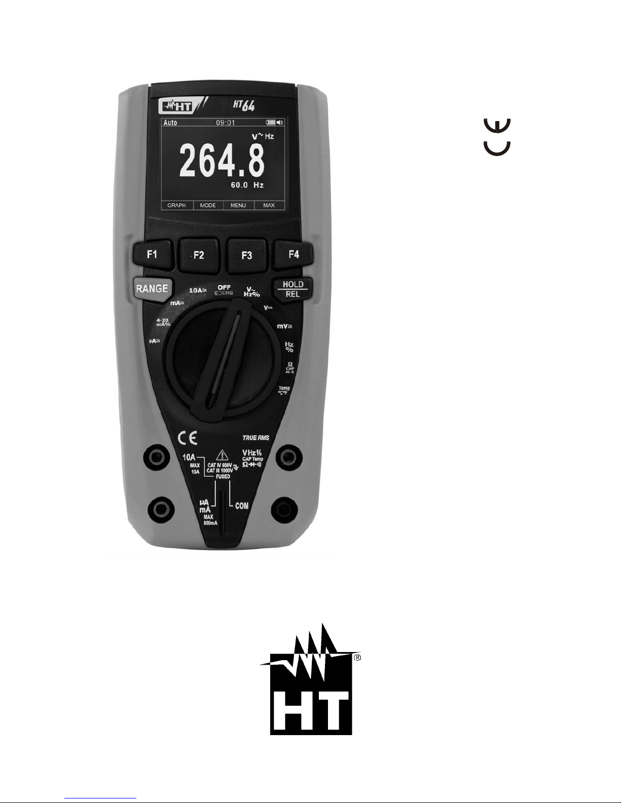
HT64
Manuale d'uso
User manual
Manual de instrucciones
Bedienungsanleitung
Manuel d’utilisation
Page 2

Indice generale
General index
Índice general
Inhalt
Table des matiéres
ITALIANO ......................... IT - 1
ENGLISH ......................... EN - 1
ESPAÑOL ........................ ES - 1
DEUTSCH ....................... DE – 1
FRANÇAIS ....................... FR - 1
Page 3

Copyright HT ITALIA 2016 Version EN 1.02 - 25/01/2016
ENGLISH
User manual
Page 4

HT64
EN - 1
Table of contents:
1. PRECAUTIONS AND SAFETY MEASURES ............................................................... 2
1.1. Preliminary instructions ..................................................................................................... 2
1.2. During use ......................................................................................................................... 3
1.3. After use ............................................................................................................................ 3
1.4. Definition of Measurement (Overvoltage) category ........................................................... 3
2. GENERAL DESCRIPTION ........................................................................................... 4
2.1. Measuring average values andTRMS values .................................................................... 4
2.2. Definition of true root mean square value and Crest factor ............................................... 4
3. PREPARATION FOR USE ........................................................................................... 5
3.1. Initial checks ...................................................................................................................... 5
3.2. Instrument power supply ................................................................................................... 5
3.3. Calibration ......................................................................................................................... 5
3.4. Storage .............................................................................................................................. 5
4. OPERATING INSTRUCTIONS ..................................................................................... 6
4.1. Description of the instrument ............................................................................................. 6
4.1.1. Description of the controls .......................................................................................................... 6
4.2. Description of function keys .............................................................................................. 7
4.2.1. HOLD/REL key ........................................................................................................................... 7
4.2.2. RANGE key ................................................................................................................................ 7
4.2.3. Function keys F1, F2, F3, F4 ...................................................................................................... 7
4.3. Description of internal functions ........................................................................................ 8
4.3.1. Description of the display ........................................................................................................... 8
4.3.2. AC+DC Voltage and Current measurement ............................................................................... 8
4.3.3. HOLD function and saving .......................................................................................................... 8
4.3.4. Relative measurement ................................................................................................................ 9
4.3.5. Saving MIN/MAX/AVERAGE and PEAK values ......................................................................... 9
4.3.6. Creating and saving graphs of measurements ......................................................................... 10
4.3.7. Instrument general menu .......................................................................................................... 10
4.4. Operating instructions ..................................................................................................... 17
4.4.1. DC, AC+DC Voltage measurement .......................................................................................... 17
4.4.2. AC Voltage measurement ........................................................................................................ 18
4.4.3. Frequency and Duty Cycle measurement ................................................................................ 19
4.4.4. Resistance measurement and continuity test ........................................................................... 20
4.4.5. Diode test .................................................................................................................................. 21
4.4.6. Capacitance measurement ....................................................................................................... 22
4.4.7. Temperature measurement with K-type probe ......................................................................... 23
4.4.8. DC, AC+DC Current measurement and e 4-20mA% reading .................................................. 24
4.4.9. AC Current measurement ......................................................................................................... 25
5. MAINTENANCE ......................................................................................................... 26
5.1. Recharging the internal battery ....................................................................................... 26
5.2. Replacement of internal fuses ......................................................................................... 27
5.3. Cleaning the instrument .................................................................................................. 27
5.4. End of life ........................................................................................................................ 27
6. TECHNICAL SPECIFICATIONS ................................................................................ 28
6.1. Technical characteristics ................................................................................................. 28
6.1.1. Reference standards ................................................................................................................ 30
6.1.2. General characteristics ............................................................................................................. 30
6.2. Environment .................................................................................................................... 30
6.2.1. Environmental conditions for use ............................................................................................. 30
6.3. Accessories ..................................................................................................................... 30
6.3.1. Accessories provided ............................................................................................................... 30
6.3.2. Optional accessories ................................................................................................................ 30
7. ASSISTANCE ............................................................................................................. 31
7.1. Warranty conditions ......................................................................................................... 31
7.2. Assistance ....................................................................................................................... 31
Page 5
HT64
EN - 2
1. PRECAUTIONS AND SAFETY MEASURES
The instrument has been designed in compliance with directive IEC/EN61010-1 relevant to
electronic measuring instruments. For your safety and in order to prevent damaging the
instrument, please carefully follow the procedures described in this manual and read all
notes preceded by symbol with the utmost attention.
Before and after carrying out measurements, carefully observe the following instructions:
Do not carry out any measurement in humid environments.
Do not carry out any measurements in case gas, explosive materials or flammables are
present, or in dusty environments.
Avoid any contact with the circuit being measured if no measurements are being
carried out.
Avoid any contact with exposed metal parts, with unused measuring probes, circuits,
etc.
Do not carry out any measurement in case you find anomalies in the instrument such
as deformation, breaks, substance leaks, absence of display on the screen, etc.
Pay special attention when measuring voltages higher than 20V, since a risk of
electrical shock exists.
In this manual, and on the instrument, the following symbols are used:
Warning: observe the instructions given in this manual; improper use could
damage the instrument or its components.
Double-insulated meter
AC voltage or current
DC voltage or current
Connection to earth
1.1. PRELIMINARY INSTRUCTIONS
This instrument has been designed for use in environments of pollution degree 2.
It can be used for VOLTAGE and CURRENT measurements on installations with CAT
IV 600V and CAT III 1000V.
We recommend following the normal safety rules devised by the procedures for
carrying out operations on live systems and using the prescribed PPE to protect the
user against dangerous currents and the instrument against incorrect use.
In case the lack of indication of the presence of voltage may represent a danger for the
operator, always carry out a continuity measurement before carrying out the
measurement on the live system, in order to confirm the correct connection and
condition of the leads.
Only the leads supplied with the instrument guarantee compliance with the safety
standards. They must be in good conditions and be replaced with identical models,
when necessary.
Do not test circuits exceeding the specified voltage limits.
Do not perform any test under environmental conditions exceeding the limits indicated
in § 6.2.1.
Check that the battery is correctly inserted.
Make sure that the LCD display and the rotary switch indicate the same function.
Page 6

HT64
EN - 3
1.2. DURING USE
Please carefully read the following recommendations and instructions:
CAUTION
Failure to comply with the caution notes and/or instructions may damage
the instrument and/or its components or be a source of danger for the
operator.
Before activating the rotary switch, disconnect the test leads from the circuit being
measured.
When the instrument is connected to the circuit being measured, do not touch any
unused terminal.
Do not measure resistance in case external voltages are present; even if the
instrument is protected, an excessive voltage may cause malfunction.
While measuring, if the value or the sign of the quantity being measured remain
unchanged, check if the HOLD function is enabled.
1.3. AFTER USE
When measurement is complete, set the rotary switch to OFF to switch off the
instrument.
If the instrument is not to be used for a long time, remove the batteries.
1.4. DEFINITION OF MEASUREMENT (OVERVOLTAGE) CATEGORY
Standard “IEC/EN61010-1: Safety requirements for electrical equipment for measurement,
control and laboratory use, Part 1: General requirements”, defines what measurement
category, commonly called overvoltage category, is. § 6.7.4: Measured circuits, reads:
(OMISSIS)
Circuits are divided into the following measurement categories:
Measurement category IV is for measurements performed at the source of the low-
voltage installation.
Examples are electricity meters and measurements on primary overcurrent protection
devices and ripple control units.
Measurement category III is for measurements performed on installations inside
buildings.
Examples are measurements on distribution boards, circuit breakers, wiring, including
cables, bus-bars, junction boxes, switches, socket-outlets in the fixed installation, and
equipment for industrial use and some other equipment, for example, stationary motors
with permanent connection to fixed installation.
Measurement category II is for measurements performed on circuits directly
connected to the low-voltage installation.
Examples are measurements on household appliances, portable tools and similar
equipment.
Measurement category I is for measurements performed on circuits not directly
connected to MAINS.
Examples are measurements on circuits not derived from MAINS, and specially
protected (internal) MAINS-derived circuits. In the latter case, transient stresses are
variable; for that reason, the standard requires that the transient withstand capability of
the equipment is made known to the user.
Page 7

HT64
EN - 4
2. GENERAL DESCRIPTION
The instrument carries out the following measurements:
DC voltage
AC, AC+DC TRMS Voltage
DC current
4-20mA% display
AC, AC+DC TRMS current
Resistance and Continuity test
Diode test
Capacity
Frequency
Duty Cycle
Temperature with K-type probe
Data Logger function and display of graphs of measured data
Each of these functions can be selected by means of the appropriate switch. The
instrument is also equipped with function keys (see § 4.2), analogue bargraph and LCD
TFT high-contrast colour display. The instrument is also equipped with an Auto Power OFF
function which automatically switches off the instrument after a certain (programmable)
idling time.
2.1. MEASURING AVERAGE VALUES ANDTRMS VALUES
Measuring instruments of alternating quantities are divided into two big families:
AVERAGE-VALUE meters: instruments measuring the value of the sole wave at
fundamental frequency (50 or 60 Hz).
TRMS (True Root Mean Square) VALUE meters: instruments measuring the TRMS
value of the quantity being tested.
With a perfectly sinusoidal wave, the two families of instruments provide identical results.
With distorted waves, instead, the readings shall differ. Average-value meters provide the
RMS value of the sole fundamental wave; TRSM meters, instead, provide the RMS value
of the whole wave, including harmonics (within the instruments bandwidth). Therefore, by
measuring the same quantity with instruments from both families, the values obtained are
identical only if the wave is perfectly sinusoidal. In case it is distorted, TRMS meters shall
provide higher values than the values read by average-value meters.
2.2. DEFINITION OF TRUE ROOT MEAN SQUARE VALUE AND CREST FACTOR
The root mean square value of current is defined as follows: “In a time equal to a period,
an alternating current with a root mean square value of 1A intensity, circulating on a
resistor, dissipates the same energy that, during the same time, would be dissipated by a
direct current with an intensity of 1A". This definition results in the numeric expression:
G=
Tt
t
dttg
T
0
0
)(
1
2
The root mean square value is indicated with the acronym RMS.
The Crest Factor is defined as the relationship between the Peak Value of a signal and its
RMS value: CF (G)=
RMS
p
G
G
This value changes with the signal waveform, for a purely
sinusoidal wave it is 2=1.41. In case of distortion, the Crest Factor takes higher values
as wave distortion increases.
Page 8

HT64
EN - 5
3. PREPARATION FOR USE
3.1. INITIAL CHECKS
Before shipping, the instrument has been checked from an electric as well as mechanical
point of view. All possible precautions have been taken so that the instrument is delivered
undamaged.
However, we recommend generally checking the instrument in order to detect possible
damage suffered during transport. In case anomalies are found, immediately contact the
forwarding agent.
We also recommend checking that the packaging contains all components indicated in §
6.3.1. In case of discrepancy, please contact the Dealer.
In case the instrument should be returned, please follow the instructions given in § 7.
3.2. INSTRUMENT POWER SUPPLY
The instrument is powered by 1x7.4V rechargeable Li-ION battery included in the
package. When the battery is flat, the symbol “ ” appears on the display. For battery
recharge, please refer to § 5.1.
3.3. CALIBRATION
The instrument has the technical specifications described in this manual. The instrument's
performance is guaranteed for one year.
3.4. STORAGE
In order to guarantee precise measurement, after a long storage time, wait for the
instrument to come back to normal condition (see § 6.2.1).
Page 9
HT64
EN - 6
4. OPERATING INSTRUCTIONS
4.1. DESCRIPTION OF THE INSTRUMENT
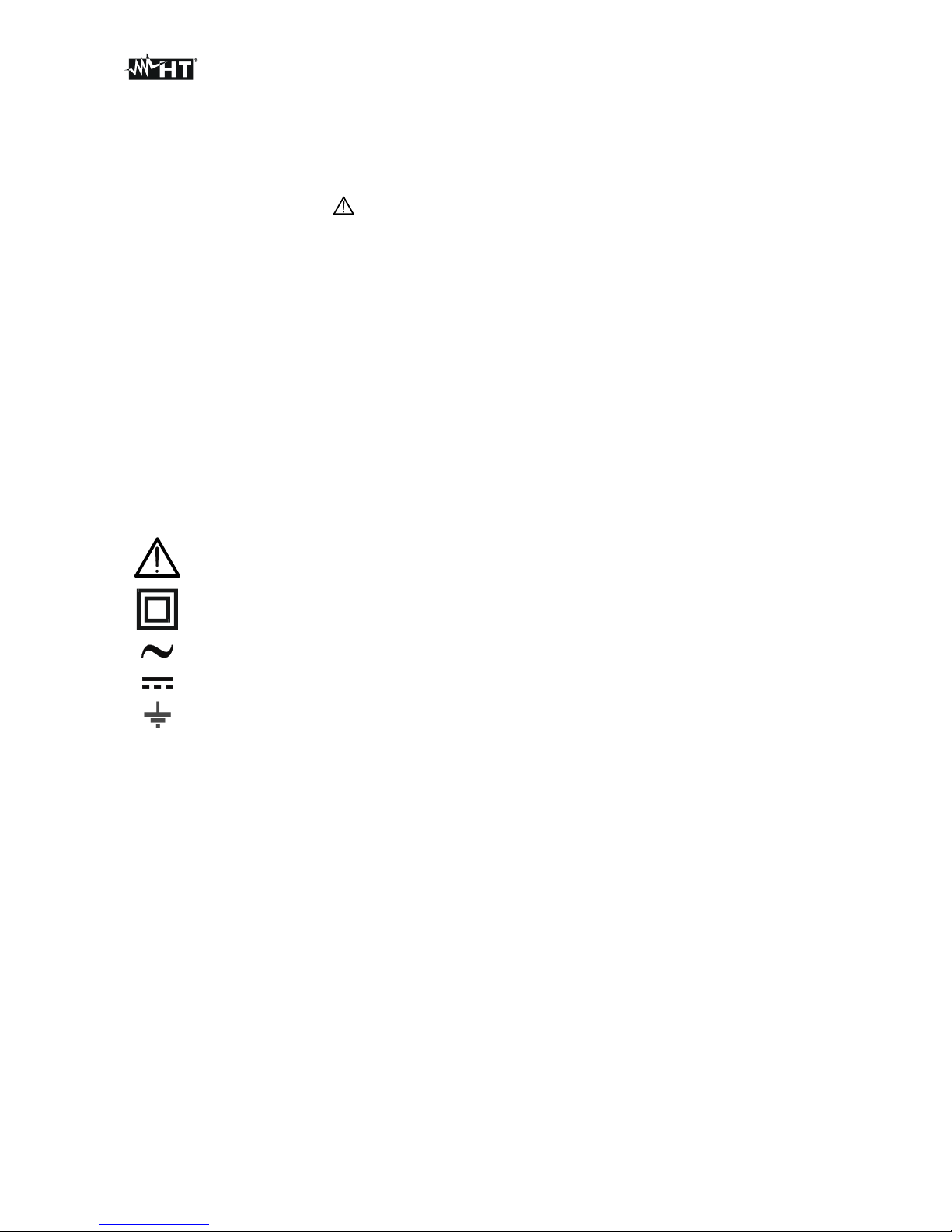
4.1.1. Description of the controls
CAPTION:
1. LCD display
2. Function key F2
3. Function key F3
4. Function key F1
5. Function key F4
6. RANGE key
7. HOLD/REL key
8. Rotary selector switch
9. Input terminal 10A
10. Input terminal
VHz%CAPTemp
11. Input terminal mAA
12. Input terminal COM
Fig. 1: Description of the instrument
Page 10

HT64
EN - 7
4.2. DESCRIPTION OF FUNCTION KEYS
4.2.1. HOLD/REL key
Pressing the HOLD/REL key freezes the value of the measured quantity on the display.
After pressing this key, the message “Hold” appears on the display. Press the HOLD/REL
key again to exit the function. To save the vale on the display, see § 4.3.3.
Press and hold the HOLD/REL key for a long time in order to activate/deactivate relative
measurement. The instrument zeroes the display and saves the displayed value as a
reference value which subsequent measurements will be referred to (see § 4.3.4). The
symbol “” appears on the display. This function is not active in position . Press and
hold the HOLD/REL key again to exit the function.
4.2.2. RANGE key
Press the RANGE key to activate the manual mode and to disable the Autorange function.
The message “Manual” appears on the upper left part of the display instead of “AUTO”. In
manual mode, press the RANGE key to change measuring range: the relevant decimal
point will change its position. The RANGE key is not active in positions , , Hz%,
Temp°C°F, mV , 10A and 4-20mA%. In Autorange mode, the instrument selects the
most appropriate ratio for carrying out measurement. If a reading is higher than the
maximum measurable value, the indication “O.L” appears on the display. Press and hold
the RANGE key for more than 1 second to exit the manual mode and restore the
Autorange mode.
4.2.3. Function keys F1, F2, F3, F4
Use keys F1, F2, F3 and F4 to manage the instrument’s internal functions (see § 4.3).
Page 11
HT64
EN - 8
4.3. DESCRIPTION OF INTERNAL FUNCTIONS
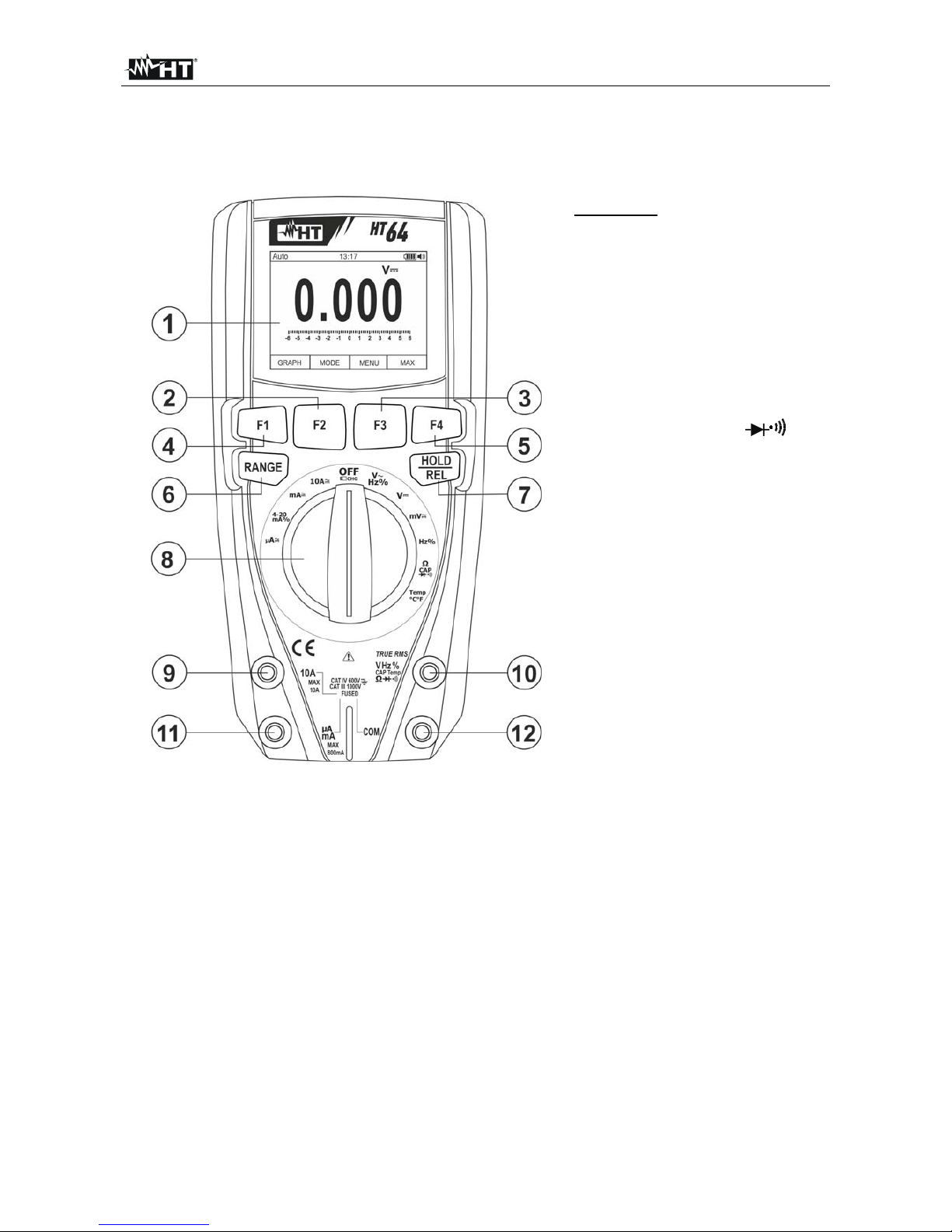
4.3.1. Description of the display
CAPTION:
1. Indication of
Automatic/Manual mode
2. Indication of the system's
time
3. Indication of battery charge
level and
activation/deactivation of key
tone (not associated with
continuity test)
4. Indication of measuring unit
5. Indication of measuring result
6. Analogue bargraph
7. Indications associated with
function keys F1, F2, F3, F4
Fig. 2: Description of the display
4.3.2. AC+DC Voltage and Current measurement
The instrument is capable of measuring a possible presence of overlapping alternating
components on a generic voltage or current direct waveform. This can be useful when
measuring typical impulsive signals of non-linear loads (e.g. welding machines, electric
ovens, etc.).
1. Select position V , 10A , mA or A
2. Press the F2 key selecting the ““ ” or “ ” modes (see Fig. 3)
3. Follow the instructions shown in § 4.4.1 or § 4.4.8
Fig. 3: AC+DC voltage or current measurement description
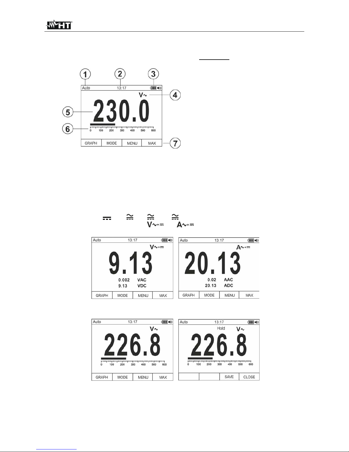
4.3.3. HOLD function and saving
Fig. 4: Saving the value frozen on the display
1. Press the HOLD/REL key again to freeze the result. The message “Hold” appears on
the display.
2. Press the F3 key to save the data in the instrument's memory.
3. Enter the General menu to display the saved result (see § 4.3.7)
Page 12

HT64
EN - 9
4.3.4. Relative measurement
Fig. 5: Relative measurement
1. Press and hold the HOLD/REL key to enter relative measurement (see Fig. 5 – right
side). The message “REL” and symbol “” appear on the display.
2. Press the F4 key to enter the General menu, save the measured result and display it
(see § 4.3.7).
4.3.5. Saving MIN/MAX/AVERAGE and PEAK values
Fig. 6: Saving MIN/MAX/AVERAGE values
1. Press the F4 key to enter the measuring mode of MAX, MIN and Average values of the
quantity to be measured (see Fig. 6 – central part). The message “MAX MIN” appears
on the display.
2. The values are automatically updated by the instrument, which emits a short beep
whenever the actually displayed values are exceeded (higher for MAX value, lower for
MIN value).
3. Press the F2 key to stop detecting the values and the F1 key to start measuring again.
4. Press the F3 key to save the measured result (see Fig. 6 – right side) and display it
(see § 4.3.7).
Fig. 7: Saving PEAK values
5. Press the F4 key to enter the measuring mode of Peak values of the quantity to be
measured (see Fig. 7 – right side). The message “PEAK” appears on the display and
the values are updated in the same way as for the MAX/MIN function.
6. Press the F2 key to stop detecting the values and the F1 key to start measuring again.
7. Press the F3 key to save the result and display it (see § 4.3.7).
Page 13

HT64
EN - 10
4.3.6. Creating and saving graphs of measurements
Fig. 8: Creating and saving a graph of measurements
1. Press the F1 key to enter the section for creating a graph of the quantity to be
measured (see Fig. 8 – left side).
2. Press the F2 (Fast) or F3 (Slow) key to set the sampling interval the instrument will
use as a reference when creating the graph. You can choose among the following
values: 0.2s, 0.5s, 1.0s, 2.0s, 5.0s, 10s
3. Press the F1 key to start creating the graph. The measuring range (automatically
inserted by the instrument) and the real-time value are displayed by the instrument
(see Fig. 8 – central part).
4. Press the F4 key to end the graph.
5. Press the F1 key to save the graph in the instrument’s memory or the F4 key to st art a
new graph (see Fig. 8 – right side).
4.3.7. Instrument general menu
1. With a measurement on the display (see Fig. 9 – left side), press function key F3 to
enter the instrument’s general menu. The screen (see Fig. 9 – right side) is shown on
the display.
Fig. 9: Instrument general menu
Saving measurements
2. Press the F1 (ENTER) key to save the measurement.
Recording data (Logger)
3. Use the F2 or F3 key to select symbol “Record” and press the F1 key (see Fig. 10 – left
side).
Fig. 10: Setting data recording
Page 14

HT64
EN - 11
4. Use the F2 or F3 key to select:
Setting of recording duration, from 1min to 23h:59min
Setting of sampling interval from 1s to 59min:59s
5. Press the F1 key to enable the editing functions and the F2 (+) and F3 (>>) keys to
carry out the desired settings.
6. Press the F1 (OK) key to confirm the settings or the F4 (CANCEL) key to go back to
editing (see Fig. 10 – right side).
7. Press the key F4 (CLOSE) to go back to the main screen
8. Select the option “Start Recording” and press the F1 key. The following screen appears
on the display
Fig. 11: Starting data recording
9. The instrument shows the remaining time and the number of samples taken in real
time, and the message “Stopped” at the end of recording (see Fig. 11 – left side). Press
the F4 (STOP) key to stop recording at any time.
10. Press the F2 key to save recorded data in the internal memory and view it again on the
display
11. Press the F3 (TREND) key to display the trend of recording (see Fig. 11 – central part).
12. Press the F4 (>>) key to move the cursor on the graph and the F2 (+) key to activate
the Zoom function of the graph, increasing resolution (symbol “Xy” where y=max zoom
dimension appears at the top of the display on the right side) (see Fig. 11
– right side).
You can zoom X1 for at least 15 measuring points, X2 for at least 30 measuring
points, X3 for at least 60 measuring points and so on for maximum 6 zooming
operations.
13. Press the F4 (BACK) key to go back to the previous screen.
Deleting the instrument
’s memory
14. Use the F2 or F3 key to select symbol “Delete” and press the F1 key (see Fig. 12 – left
side).
Fig. 12: Deleting the internal memory
Page 15

HT64
EN - 12
15. Use the F2 or F3 key to select the options:
Delete all Measurements all snapshots (measurements) are deleted
Delete all Recordings all recordings are deleted
Delete all Graphs all graphs are deleted.
16. Press the F1 (OK) key to carry out the selected operation (a confirmation message is
shown by the instrument).
General settings of the instrument
17. Use the F2 or F3 key to select symbol “Setup” and press the F1 key (see Fig. 13 – left
side).
Fig. 13: General settings of the instrument
18. Use the F2 or F3 key to select the options:
Reset restores the instrument’s default conditions.
Format allows activating the key tone, setting the format of date/time and of the
displayed numbers (decimal comma or point).
General allows setting the system’s date/time, defining the Auto Power OFF
interval, the background colour and the display’s font colour and type, and choosing
the system’s language.
Meter Info provides information on the internal Firmware version and on the
memory
’s available space.
19. Press the F1 (ENTER) key to carry out the selected operation or the F4 (CANCEL) key
to go back to the measuring screen.
General settings of the instrument
– Reset
Fig. 14: Activating the instrument
’s reset
20. Press the F1 (OK) key to activate the Reset.
21. The Reset operation do not deletes the instrument’s internal memory
Page 16

HT64
EN - 13
General settings of the instrument – Format
Fig. 15: Setting the Format Menu
22. Use the F2 or F3 key to select the options:
Key tone allows activating/deactivating the tone of the function keys.
Numeric Format allows defining the format of the numbers shown on the display
among the options: 0.000 (decimal point) and 0,000 (comma)
Date Format allows defining the format of the system date between the options:
MM/DD/YY and DD/MM/YY
Time Format allows defining the format of the system time between the options:
12 HOURS and 24 HOURS
23. Use the F1 (EDIT) key and the F2 and F3 keys for settings or the F4 key to go back to
the previous screen.
General settings of the instrument – Display
Fig. 16: Setting the Display Menu
24. Use the F2 or F3 key to select the options:
Set Date allows setting the system’s date as defined in the Format menu.
Set Time allows setting the system’s time as defined in the Format menu.
Auto Power OFF allows defining the instrument’s auto power off interval when
idling in the range: 5min 60min with resolution 1min. Set value 00 to disable the
function. Press the F3 key to switch on the instrument again after it has
automatically switched off.
Foreground allows defining the display’s background colour and the colour of
the font.
Select Font allows defining the type of font or the display among the available
options (0, 1, 2).
Language allows selecting the system’s language among the options: Italian,
English, Spanish, German and French
Page 17

HT64
EN - 14
General settings of the instrument – Instrument Info
Fig. 17: Display of Menu Instrument Info
25. The instrument shows the following information:
Firmware version internal Firmware version
Free memory per centage values of the remaining free space in the memory for
saving snapshots (SAVE), recordings (REC) and graphs (GRAPH).
26. Press the F4 key to go back to the previous screen
Recalling graphs to the display
Fig. 18: Recalling graphs to the display
27. Use the F2 or F3 key to select symbol “View G” and press the F1 key (see Fig. 18 – left
side).
28. Use the F2 (PREV) or F3 (NEXT) keys to select the desired graph among the ones
saved in the instrument's memory and press key F1 (ENTER) to open the graph (see
Fig. 18 – central part).
29. Use the F2 (<<) or F3 (>>) keys to move the cursor within the graph in the two
directions, observing the corresponding value at the bottom of the display (see Fig. 18
– right side).
30. Press the F1 (DELETE) key to delete the selected graph or the F4 (BACK) key to go
back to the previous screen.
Page 18

HT64
EN - 15
Recalling measured data (snapshots) on the display
Fig. 19: Recalling measured data (snapshots) on the display
31. Use the F2 or F3 key to select symbol “View M” and press the F1 key (see Fig. 19 – left
side).
32. Use the F2 (PREV) or F3 (NEXT) key to select and view the desired measure among
the ones saved in the instrument's memory (see Fig. 19
– right side). The measure
reference appears at the bottom of the display on the right side.
33. Press the F1 (DELETE) key to delete the selected measure or the F4 (CLOSE) key to
go back to main screen
Recalling recordings to the display
Fig. 20: Recalling recordings to the display
34. Use the F2 or F3 key to select symbol “View R” and press the F1 key (see Fig. 20 – left
side).
35. Use the F2 (PREV) or F3 (NEXT) key to select the desired recording among the ones
saved in the instrument's memory (see Fig. 20 – central part). The recording reference
appears at the bottom of the display.
36. Press the F1 (TREND) key to display the trend of recording.
37. Press the F3 (>>) key to move the cursor on the graph and observe the corresponding
value at the bottom of the display.
38. Press the F2 (+) key to activate (if available) the zooming function of the graph.
39. Press the F1 (DELETE) key to delete the selected recording or the F4 (BACK) key to
go back to the previous screen.
Page 19

HT64
EN - 16
Help on line on the display
Fig. 21: Help on line on the display
40. Use the F2 or F3 key to select symbol “Help” and press the F1 key (see Fig. 21).
41. Use the F2 (UP) or F3 (DOWN) to browse the pages of the context on-line help.
42. Press the F4 (CLOSE) key to go back to the main screen
Page 20

HT64
EN - 17
4.4. OPERATING INSTRUCTIONS
4.4.1. DC, AC+DC Voltage measurement
CAUTION
The maximum input DC voltage is 1000V. Do not measure voltages
exceeding the limits given in this manual. Exceeding voltage limits could
result in electrical shocks to the user and damage to the instrument.
Fig. 22: Use of the instrument for DC voltage measurement
1. Select positions V or mV.
2. Insert the red cable into input terminal VHz%CAPTemp and the black cable into
input terminal COM.
3. Position the red lead and the black lead respectively in the spots with positive and
negative potential of the circuit to be measured (see Fig. 22). The display shows the
value of voltage.
4. If the display shows the message "O.L", select a higher range.
5. When symbol "-" appears on the instrument’s display, it means that voltage has the
opposite direction with respect to the connection in Fig. 22.
6. To use the HOLD, RANGE and REL function, see § 4.2.
7. For AC+DC measurement, see § 4.3.2 and to use the internal functions, see § 4.3.
Page 21

HT64
EN - 18
4.4.2. AC Voltage measurement
CAUTION
The maximum input AC voltage is 1000V. Do not measure voltages
exceeding the limits given in this manual. Exceeding voltage limits could
result in electrical shocks to the user and damage to the instrument.
Fig. 23: Use of the instrument for AC voltage measurement
1. Select positions VHz% or mV
2. In position mV , press the F2 (MODE) key to view symbol “” on the display.
3. Insert the red cable into input terminal VHz%CAPTemp
and the black cable into
input terminal COM.
4. Position the red lead and the black lead respectively in the spots of the circuit to be
measured (see Fig. 23). The display shows the value of voltage.
5. If the display shows the message "O.L", select a higher range.
6. Press the F2 (MODE) key to select measurements “Hz” or “%” in order to display the
values of frequency and duty cycle of input voltage. Press the F1(TRIG) key to select
the positive or negative half-wave of the function “%”The bargraph is not active in these
functions.
7. To use the HOLD, RANGE and REL function, see § 4.2.
8. To use the internal functions, see § 4.3.
Page 22

HT64
EN - 19
4.4.3. Frequency and Duty Cycle measurement
CAUTION
The maximum input AC voltage is 1000V. Do not measure voltages
exceeding the limits given in this manual. Exceeding voltage limits could
result in electrical shocks to the user and damage to the instrument.
Fig. 24: Use of the instrument for frequency measurement and duty cycle test.
1. Select position Hz%.
2. Press the F2 (MODE) key to select measurements “Hz” or “%” in order to display the
values of frequency and duty cycle of input voltage.
3. Insert the red cable into input terminal VHz%CAPTemp and the black cable into
input terminal COM.
4. Position the red lead and the black lead respectively in the spots of the circuit to be
measured (see Fig. 24). The value of frequency (Hz) or of duty cycle (%) is shown on
the display. The bargraph is not active in these functions.
5. To use the HOLD and REL function, see § 4.2.
6. To use the internal functions, see § 4.3.
Page 23

HT64
EN - 20
4.4.4. Resistance measurement and continuity test
CAUTION
Before attempting any resistance measurement, cut off power supply from
the circuit to be measured and make sure that all capacitors are discharged,
if present.
Fig. 25: Use of the instrument for resistance measurement and continuity test
1. Select position CAP
2. Insert the red cable into input terminal VHz%CAPTemp and the black cable into
input terminal COM.
3. Position the test leads in the desired spots of the circuit to be measured (see Fig. 25).
The display shows the value of resistance.
4. If the display shows the message "O.L", select a higher range.
5. Press the F2 (MODO) key to select measurement “ ” relevant to the continuity test,
and position the test leads in the desired spots of the circuit to be measured.
6. The value of resistance (which is only indicative) is di splayed in and the instrument
sounds if the value of resistance is <50
7. To use the HOLD, RANGE and REL function, see § 4.2.
8. To use the internal functions, see § 4.3.
Page 24

HT64
EN - 21
4.4.5. Diode test
CAUTION
Before attempting any resistance measurement, cut off power supply from
the circuit to be measured and make sure that all capacitors are discharged,
if present.
Fig. 26: Use of the instrument for diode test
1. Select position CAP
2. Press the F2 (MODE) key to select
“ ” measurement.
3. Insert the red cable into input terminal VHz%CAPTemp and the black cable into
input terminal COM.
4. Position the leads at the ends of the diode to be tested (see Fig. 26), respecting the
indicated polarity. The value of directly polarized threshold voltage is shown on the
display.
5. If threshold value is equal to 0mV, the P-N junction of the diode is short-circuited.
6. If the display shows the message “O.L”, the terminals of the diode are reversed with
respect to the indication given in Fig. 26 or the P-N junction of the diode is damaged.
7. To use the HOLD and REL function, see § 4.2.
8. To use the internal functions, see § 4.3.
Page 25

HT64
EN - 22
4.4.6. Capacitance measurement
CAUTION
Before carrying out capacitance measurements on circuits or capacitors, cut
off power supply from the circuit being tested and let all capacitance in it be
discharged. When connecting the multimeter and the capacitance to be
measured, respect the correct polarity (when required).
Fig. 27: Use of the instrument for Capacitance measurement
1. Select position CAP
2. Press the F2 (MODE) key until the symbol “nF” is displayed.
3. Insert the red cable into input terminal VHz%CAPTemp and the black ca ble
into input terminal COM.
4. Press the REL/ key before carrying out measurements.
5. Position the leads at the ends of the capacitor to be tested, respecting, if necessary ,
the positive (red cable) and negative (black cable) polarity (see Fig. 27). The display
shows the value of capacitance. The bargraph is not active in this function.
6. The message “O.L.” indicates that the value of capacitance exceeds the maximum
measurable value.
7. To use the HOLD and REL function, see § 4.2.
8. To use the internal functions, see § 4.3.
Page 26

HT64
EN - 23
4.4.7. Temperature measurement with K-type probe
CAUTION
Before attempting any temperature measurement, cut off power supply from
the circuit to be measured and make sure that all capacitors are discharged,
if present.
Fig. 28: Use of the instrument for Temperature measurement
1. Select position Temp°C°F
2. Press the F2 (MODE) key until the symbol “°C” or “°F” is displayed.
3. Insert the provided adapter into input terminals VHz%CAPTemp (polarity +) and
COM (polarity -) (see Fig. 28)
4. Connect the provided K-type wire probe or the optional K-type thermocouple (see §
6.3.2) to the instrument by means of the adapter, respecting the positive and negative
polarity on it. The display shows the value of temperature. The bargraph is not active in
this function.
5. The message “O.L.” indicates that the value of temperature exceeds the maximum
measurable value.
6. To use the HOLD and REL function, see § 4.2.
7. To use the internal functions, see § 4.3.
Page 27

HT64
EN - 24
4.4.8. DC, AC+DC Current measurement and e 4-20mA% reading
CAUTION
Maximum input DC current is 10A (input 10A) or 600mA (input mAA). Do
not measure currents exceeding the limits given in this manual. Exceeding
voltage limits could result in electrical shocks to the user and damage to the
instrument.
Fig. 29: Use of the instrument for DC current measurement and 4-20mA% reading.
1. Cut off power supply from the circuit to be measured.
2. Select position A , mA or 10A to measure DC current or the same position 4-
20mA% for 4-20mA% reading.
3. Insert the red cable into input terminal 10A or into input terminal mAA and the black
cable into input terminal COM.
4. Connect the red lead and the black lead in series to the circuit whose current you want
to measure, respecting polarity and current direction (see Fig. 29).
5. Supply the circuit to be measured.
6. The value of DC current (see Fig. 29 – left side) appears on the display.
7. The value of reading 4-20mA% (0mA = -25%, 4mA = 0%, 20mA = 100% and 24mA =
125%) (see Fig. 29 – right side) appears on the display. The bargraph is not active in
this function.
8. If the display shows the message “O.L”, the maximum measurable value has been
reached.
9. When symbol "-" appears on the instrument's display, it means that current has the
opposite direction with respect to the connection in Fig. 29.
10. To use the HOLD, RANGE and REL functions, see § 4.2.
11. For AC+DC measurement, see § 4.3.2 and to use the internal functions, see § 4.3
Page 28

HT64
EN - 25
4.4.9. AC Current measurement
CAUTION
Maximum input AC current is 10A (input 10A) or 600mA (input mAA). Do
not measure currents exceeding the limits given in this manual. Exceeding
voltage limits could result in electrical shocks to the user and damage to the
instrument.
Fig. 30: Use of the instrument for AC current measurement
1. Cut off power supply from the circuit to be measured.
2. Select positions A , mA or 10A.
3. Press the F2 (MODE) key to select “AC” measurement.
4. Insert the red cable into input terminal 10A or into input terminal mAA and the black
cable into input terminal COM.
5. Connect the red lead and the black lead in series to the circuit whose current you want
to measure (see Fig. 30).
6. Supply the circuit to be measured. The display shows the value of current.
7. If the display shows the message “O.L”, the maximum measurable value has been
reached.
8. To use the HOLD, RANGE and REL functions, see § 4.2.
9. To use the internal functions, see § 4.3.
Page 29

HT64
EN - 26
5. MAINTENANCE
CAUTION
Only expert and trained technicians should perform maintenance
operations. Before carrying out maintenance operations, disconnect all
cables from the input terminals.
Do not use the instrument in environments with high humidity levels or
high temperatures. Do not expose to direct sunlight.
Always switch off the instrument after use. In case the instrument is not to
be used for a long time, remove the battery to avoid liquid leaks that could
damage the instrument’s internal circuits.
5.1. RECHARGING THE INTERNAL BATTERY
When the LCD displays symbol “ ”, it is necessary to recharge the internal battery.
Fig. 31: Recharging the internal battery
1. Position the rotary switch to OFF and remove the cables from the input terminals.
2. Insert the interface of the battery charger power supply into the instrument, into the four
input terminals (see Fig. 31).
3. Insert the connector of the power supply into the interface and connect the power
supply to the electric mains. The green LED should light up.
4. A blinking symbol o a green battery appears on the display. The recharging process is
complete when the symbol is steady.
5. Disconnect the battery charger from the instrument when the operation is complete.
Page 30

HT64
EN - 27
5.2. REPLACEMENT OF INTERNAL FUSES
Fig. 32: Replacement of internal fuses
1. Position the rotary switch to OFF and remove the cables from the input terminals.
2. Turn the fastening screw of the battery compartment cover from position “ ” to position
“ ” and remove it (see Fig. 32)
3. Remove the damaged fuse and insert a new fuse of the same type (see § 6.1.2).
4. Restore the battery compartment cover into place and turn the fastening screw from
position “ ” to position “ ”.
5.3. CLEANING THE INSTRUMENT
Use a soft and dry cloth to clean the instrument. Never use wet cloths, solvents, water, etc.
5.4. END OF LIFE
WARNING: the symbol on the instrument indicates that the appliance and its
accessories must be collected separately and correctly disposed of.
Page 31

HT64
EN - 28
6. TECHNICAL SPECIFICATIONS
6.1. TECHNICAL CHARACTERISTICS
Accuracy calculated as [%reading + (num. digits*resolution)] at 18°C 28°C <75%HR
DC Voltage
Range Resolution Accuracy Input impedance
Protection against
overcharge
600.0mV 0.1mV
(0.1%reading + 5digits)
>10M
1000VDC/ACrms
6.000V 0.001V
60.00V 0.01V
600.0V 0.1V
(0.2%reading + 5digits)
1.000V 1V
AC TRMS Voltage
Range Resolution
Accuracy (*)
Protection against
overcharge
(50Hz60Hz) (61Hz1kHz)
600.0mV 0.1mV
(0.9%reading + 5digits) (3.0%reading + 5dgt)
1000VDC/ACrms
6.000V 0.001V
60.00V 0.01V
600.0V 0.1V
1.000V 1V
(*) Accuracy specified from 10% to 100% of the measuring range, Input impedance: > 9M ;
Accuracy PEAK function: ±10%rdg, PEAK response time: 1ms
AC+ DC TRMS Voltage
Range Resolution
Accuracy
(50Hz1kHz)
Input impedance
Protection against
overcharge
6.000V 0.001V
(3.0%reading + 20dgt) >10M
1000VDC/ACrms
60.00V 0.01V
600.0V 0.1V
1.000V 1V
DC Current
Range Resolution Accuracy Protection against overcharge
600.0A 0.1A
(0.9%reading + 5digits)
Quick fuse 800mA/1000V
6000A 1A
60.00mA 0.01mA
600.0mA 0.1mA
(0.9%reading + 8digits)
10.00A 0.01A
(1.5%reading + 8digits)
Quick fuse 10A/1000V
AC TRMS Current
Range Resolution
Accuracy (*) (50Hz1kHz)
Protection against overcharge
600.0A 0.1A
(1.2%reading + 5digits)
Quick fuse 800mA/1000V
6000A 1A
60.00mA 0.01mA
600.0mA 0.1mA
10.00A 0.01A
(1.5%reading + 5digits)
Quick fuse 10A/1000V
(*) Accuracy specified from 5% to 100% of the measuring range
Accuracy PEAK function: ±10%rdg , AC+DC TRMS Current: accuracy (50Hz1kHz): (3.0%reading + 20dgt)
4-20mA% reading
Range Resolution Accuracy Correspondence
-25%125%
0.1%
50dgt
0mA=-25%, 4mA=0%, 20mA=100%, 24mA=125%
Page 32

HT64
EN - 29
Diode test
Function Test current Max voltage with open circuit
<1.5mA 3.2VDC
Resistance and Continuity test
Range Resolution Accuracy Buzzer
Protection against
overcharge
600.0 0.1 (0.8%reading + 10dgt)
<50
1000VDC/ACrms
6.000k 0.001k
(0.8%reading + 5digits)
60.00k 0.01k
600.0k 0.1k
6.000M 0.001M
60.00M 0.01M (2.5%reading + 10dgt)
Frequency (electronic circuits)
Range Resolution Accuracy
Protection against
overcharge
40.00Hz 10kHz 0.01Hz 0.001kHz (0.5%reading)
1000VDC/ACrms
Sensitivity: 2Vrms
Frequency (electronic circuits)
Range Resolution Accuracy
Protection against
overcharge
60.00Hz 0.01Hz
(0.09%rdg+5digits)
1000VDC/ACrms
600.0Hz 0.1Hz
6.000kHz 0.001kHz
60.00kHz 0.01kHz
600.0kHz 0.1kHz
1.000MHz 0.001MHz
Sensitivity: >2Vrms (@ 20% 80% duty cycle) and f<100kHz; >5Vrms (@ 20% 80% duty cycle) and f>100kHz
Duty Cycle
Range Resolution Accuracy
0.1% 99.9%
0.1%
(1.2%reading + 2digits)
Pulse frequency range: 40Hz 10kHz, Pulse amplitude: ±5V (100s 100ms)
Capacity
Range Resolution Accuracy Protection against overcharge
60.00nF 0.01nF
(1.5%reading + 20dgt)
1000VDC/ACrms
600.0nF 0.1nF
(1.2%reading + 8digits)
6.000F 0.001F (1.5%reading + 8digits)
60.00F 0.01F (1.2%reading + 8digits)
600.0F 0.1F (1.5%reading + 8digits)
6.000mF 0.001mF
(2.5%reading + 20dgt)
Temperature with K-type probe
Range Resolution Accuracy (*)
Protection against
overcharge
-40.0°C ÷ 600.0°C 0.1°C
(1.5%reading + 3°C)
1000VDC/ACrms
600°C ÷ 1350°C 1°C
-40.0°F ÷ 600.0°F 0.1°F
(1.5%rdg+ 5.4°F)
600°F ÷ 2462°F 1°F
(*) Instrument accuracy without probe ; Specified accuracy with stable environmental temperature at ±1°C
For long-lasting measurements, reading increases by 2°C
Page 33

HT64
EN - 30
6.1.1. Reference standards
Safety: IEC/EN61010-1
EMC: IEC/EN 61326-1
Insulation: double insulation
Pollution level: 2
Overvoltage category: CAT IV 600V, CAT III 1000V
Max operating altitude: 2000m (6562ft)
6.1.2. General characteristics
Mechanical characteristics
Size (L x W x H): 175 x 85 x 55mm (7 x 3 x 2in)
Weight (batteries included): 400g
Power supply
Battery type: 1x7.4V rechargeable Li-ION battery, 1300mAh
Battery charger power supply: 100/240VAC, 50/60Hz, 10VDC, 1A
Low battery indication: symbol “ ” on the display
Auto Power Off: after 5 60min minutes’ idling (may be disabled)
Fuses: F10A/1000V, 10 x 38mm (input 10A)
F800mA/1000V, 6 x 32mm (input mAA)
Display
Conversion: TRMS
Characteristics: colour TFT, 6000 dots with bargraph
Sampling frequency: 3 times/s
6.2. ENVIRONMENT
6.2.1. Environmental conditions for use
Reference temperature: 18°C 28°C (64°F 82°F)
Operating temperature: 5°C ÷ 40°C (41°F 104°F)
Allowable relative humidity: <80%HR
Storage temperature: -20° ÷ 60°C (-4°F 140°F)
Storage humidity: <80%HR
This instrument satisfies the requirements of Low Voltage Directive 2006/95/EC
(LVD) and of EMC Directive 2004/108/EC
This instrument satisfies the requirements of European Directive 2011/65/EU (RoHS)
and 2012/19/EU (WEEE)
6.3. ACCESSORIES
6.3.1. Accessories provided
Pair of test leads
Adapter + K-type wire probe
Li-ION rechargeable battery
Battery charger power supply + interface Code A64
Carrying bag
User Manual
6.3.2. Optional accessories
Pair of test leads Code KIT4000A
K-type probe for air and gas temperature Code TK107
K-type probe for semisolid substance temperature Code TK108
K-type probe for liquid substance temperature Code TK109
K-type probe for surface temperature Code TK110
K-type probe for surface temperature with 90° tip Code TK111
Page 34

HT64
EN - 31
7. ASSISTANCE
7.1. WARRANTY CONDITIONS
This instrument is warranted against any material or manufacturing defect, in compliance
with the general sales conditions. During the warranty period, defective parts may be
replaced. However, the manufacturer reserves the right to repair or replace the product.
Should the instrument be returned to the After-sales Service or to a Dealer, transport will
be at the Customer's charge. However, shipment will be agreed in advance. A report will
always be enclosed to a shipment, stating the reasons for the product's return. Only use
original packaging for shipment. Any damage due to the use of non-original packaging
material will be charged to the Customer. The manufacturer declines any responsibility for
injury to people or damage to property.
The warranty shall not apply in the following cases:
Repair and/or replacement of accessories and battery (not covered by warranty).
Repairs that may become necessary as a consequence of an incorrect use of the
instrument or due to its use together with non-compatible appliances.
Repairs that may become necessary as a consequence of improper packaging.
Repairs which may become necessary as a consequence of interventions performed
by unauthorized personnel.
Modifications to the instrument performed without the manufacturer's explicit
authorization.
Use not provided for in the instrument's specifications or in the instruction manual.
The content of this manual cannot be reproduced in any form without the manufacturer's
authorization.
Our products are patented and our trademarks are registered. The manufacturer
reserves the right to make changes in the specifications and prices if this is due to
improvements in technology.
7.2. ASSISTANCE
If the instrument does not operate properly, before contacting the After-sales Service,
please check the conditions of battery and cables and replace them, if necessary. Should
the instrument still operate improperly, check that the product is operated according to the
instructions given in this manual. Should the instrument be returned to the After-sales
Service or to a Dealer, transport will be at the Customer's charge. However, shipment will
be agreed in advance. A report will always be enclosed to a shipment, stating the reasons
for the product's return. Only use original packaging for shipment; any damage due to the
use of non-original packaging material will be charged to the Customer.
Page 35

Page 36

HT INSTRUMENTS SA
C/ Legalitat, 89
08024 Barcelona - ESP
Tel.: +34 93 408 17 77, Fax: +34 93 408 36 30
eMail: info@htinstruments.com
eMail: info@htinstruments.es
Web: www.htinstruments.es
HT ITALIA SRL
Via della Boaria, 40
48018 Faenza (RA) - ITA
Tel: +39 0546 621002
Fax: +39 0546 621144
eMail: ht@htitalia.it
Web: www.ht-instruments.com
HT INSTRUMENTS BRASIL
Rua Aguaçu, 171, bl. Ipê, sala 108
13098321 Campinas SP - BRA
Tel: +55 19 3367.8775
Fax: +55 19 9979.11325
eMail: vendas@ht-instruments.com.br
Web: www.ht-instruments.com.br
HT INSTRUMENTS USA LLC
3145 Bordentown Avenue W3
08859 Parlin - NJ - USA
Tel: +1 719 421 9323
eMail: sales@ht-instruments.us
Web: www.ht-instruments.com
HT INSTRUMENTS GMBH
Am Waldfriedhof 1b
D-41352 Korschenbroich - GER
Tel: +49 (0) 2161 564 581
Fax: + 49 (0) 2161 564 583
eMail: info@ht-instruments.de
Web: www.ht-instruments.de
HT ITALIA CHINA OFFICE
意大利HT中国办事处
Room 3208, 490# Tianhe road, Guangzhou - CHN
地址:广州市天河路490号壬丰大厦3208室
Tel.: +86 400-882-1983, Fax: +86 (0) 20-38023992
eMail: zenglx_73@hotmail.com
Web: www.guangzhouht.com
 Loading...