

Page 1
Copyright HT ITALIA 2016 Release 1.02 - 25/01/2016
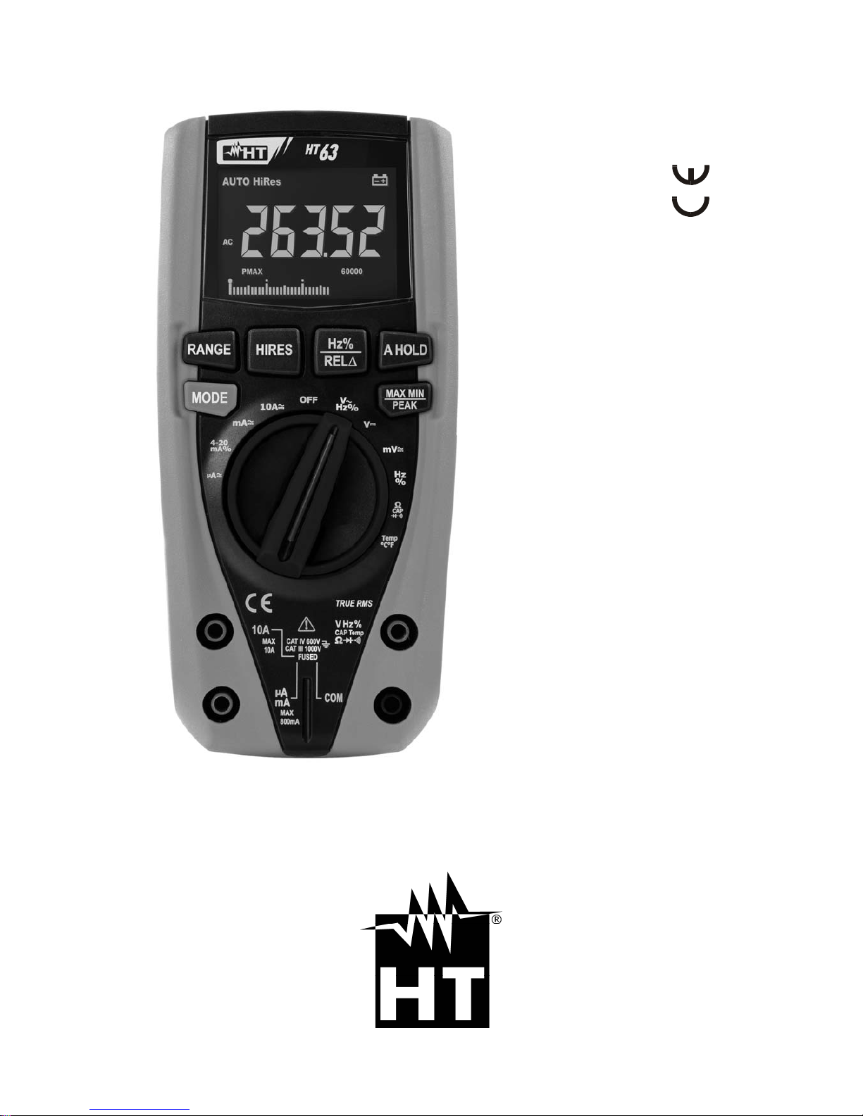
HT63
Manuale d'uso
User manual
Manual de instrucciones
Bedienungsanleitung
Manuel d’utilisation
Page 2

Page 3

Indice generale
General index
Índice general
Inhalt
Table des matiéres
ITALIANO ......................... IT - 1
ENGLISH ......................... EN - 1
ESPAÑOL ........................ ES - 1
DEUTSCH ....................... DE – 1
FRANÇAIS ....................... FR - 1
Page 4

Page 5

Copyright HT ITALIA 2015 Versione IT 1.02 - 25/01/2016
ITALIANO
Manuale d’uso
Page 6

HT63
IT - 1
Indice:
1. PRECAUZIONI E MISURE DI SICUREZZA ................................................................. 2
1.1. Istruzioni preliminari .......................................................................................................... 2
1.2. Durante l’utilizzo ................................................................................................................ 3
1.3. Dopo l’utilizzo .................................................................................................................... 3
1.4. Definizione di Categoria di misura (Sovratensione) .......................................................... 3
2. DESCRIZIONE GENERALE ......................................................................................... 4
2.1. Strumenti di misura a Valore medio ed a Vero valore efficace ......................................... 4
2.2. Definizione di Vero valore efficace e Fattore di cresta ...................................................... 4
3. PREPARAZIONE ALL’UTILIZZO ................................................................................. 5
3.1. Controlli iniziali .................................................................................................................. 5
3.2. Alimentazione dello strumento .......................................................................................... 5
3.3. Taratura ............................................................................................................................. 5
3.4. Conservazione .................................................................................................................. 5
4. ISTRUZIONI OPERATIVE ............................................................................................ 6
4.1. Descrizione dello strumento .............................................................................................. 6
4.1.1. Descrizione dei comandi ............................................................................................................ 6
4.2. Descrizione dei tasti funzione ............................................................................................ 7
4.2.1. Tasto A HOLD .................................................................................................................. .......... 7
4.2.2. Tasto RANGE ............................................................................................................................. 7
4.2.3. Tasto MAX MIN/PEAK ................................................................................................................ 7
4.2.4. Tasto Hz%/REL ........................................................................................................................ 7
4.2.5. Tasto MODE ............................................................................................................................... 8
4.2.6. Tasto HIRES ............................................................................................................................... 8
4.2.7. Disabilitazione funzione Autospegnimento ................................................................................. 8
4.3. Descrizione delle funzioni del selettore ............................................................................. 9
4.3.1. Misura di Tensione DC ............................................................................................................... 9
4.3.2. Misura di Tensione AC ............................................................................................................. 10
4.3.3. Misura di Frequenza e Duty Cycle ........................................................................................... 11
4.3.4. Misura di Resistenza e Test Continuità .................................................................................... 12
4.3.5. Prova Diodi ............................................................................................................................... 13
4.3.6. Misura di Capacità .................................................................................................................... 14
4.3.7. Misura di Temperatura con sonda K ........................................................................................ 15
4.3.8. Misura di Corrente DC e lettura 4-20mA% ............................................................................... 16
4.3.9. Misura di Corrente AC .............................................................................................................. 17
5. MANUTENZIONE ....................................................................................................... 18
5.1. Sostituzione batterie e fusibili interni ............................................................................... 18
5.2. Pulizia dello strumento .................................................................................................... 18
5.3. Fine vita ........................................................................................................................... 18
6. SPECIFICHE TECNICHE ........................................................................................... 19
6.1. Caratteristiche Tecniche .................................................................................................. 19
6.1.1. Norme di riferimento ................................................................................................................. 21
6.1.2. Caratteristiche generali ............................................................................................................. 21
6.2. Ambiente ......................................................................................................................... 21
6.2.1. Condizioni ambientali di utilizzo................................................................................................ 21
6.3. Accessori ......................................................................................................................... 21
6.3.1. Accessori in dotazione .............................................................................................................. 21
6.3.2. Accessori opzionali ................................................................................................................... 21
7. ASSISTENZA ............................................................................................................. 22
7.1. Condizioni di garanzia ..................................................................................................... 22
7.2. Assistenza ....................................................................................................................... 22
Page 7
HT63
IT - 2
1. PRECAUZIONI E MISURE DI SICUREZZA
Lo strumento è stato progettato in conformità alla direttiva IEC/EN61010-1, relativa agli
strumenti di misura elettronici. Per la Sua sicurezza e per evitare di danneggiare lo
strumento, La preghiamo di seguire le procedure descritte nel presente manuale e di
leggere con particolare attenzione tutte le note precedute dal simbolo .
Prima e durante l’esecuzione delle misure attenersi scrupolosamente alle seguenti
indicazioni:
Non effettuare misure in ambienti umidi.
Non effettuare misure in presenza di gas o materiali esplosivi, combustibili o in
ambienti polverosi.
Evitare contatti con il circuito in esame se non si stanno effettuando misure.
Evitare contatti con parti metalliche esposte, con terminali di misura inutilizzati, circuiti,
ecc.
Non effettuare alcuna misura qualora si riscontrino anomalie nello strumento come,
deformazioni, rotture, fuoriuscite di sostanze, mancate visualizzazioni a display, ecc.
Prestare particolare attenzione quando si effettuano misure di tensioni superiori a 20V
in quanto è presente il rischio di shock elettrici.
Nel presente manuale e sullo strumento sono utilizzati i seguenti simboli:
Attenzione: attenersi alle istruzioni riportate nel manuale; un uso improprio
potrebbe causare danni allo strumento o ai suoi componenti
Strumento con doppio isolamento
Tensione AC o Corrente AC
Tensione o Corrente DC
Riferimento di terra
1.1. ISTRUZIONI PRELIMINARI
Questo strumento è stato progettato per un utilizzo in un ambiente con livello di
inquinamento 2.
Può essere utilizzato per misure di TENSIONE e CORRENTE su installazioni in CAT
IV 600V, CAT III 1000V
La invitiamo a seguire le normali regole di sicurezza previste dalle procedure per i
lavori sotto tensione ed a utilizzare i DPI previsti orientati alla protezione contro correnti
pericolose e a proteggere lo strumento contro un utilizzo errato
Nel caso in cui la mancata indicazione della presenza di tensione possa costituire
rischio per l’operatore effettuare sempre una misura di continuità prima della misura in
tensione per confermare il corretto collegamento e stato dei puntali
Solo i puntali forniti a corredo dello strumento garantiscono gli standard di sicurezza.
Essi devono essere in buone condizioni e sostituiti, se necessario, con modelli identici.
Non effettuare misure su circuiti che superano i limiti di tensione specificati.
Non effettuare misure in condizione ambientali diverse da quelle indicate nel § 6.2.1
Controllare se la batteria è inserita correttamente
Controllare che il display LCD e il selettore indichino la stessa funzione
Page 8

HT63
IT - 3
1.2. DURANTE L’UTILIZZO
La preghiamo di leggere attentamente le raccomandazioni e le istruzioni seguenti:
ATTENZIONE
La mancata osservazione delle Avvertenze e/o Istruzioni può danneggiare
lo strumento e/o i suoi componenti o essere fonte di pericolo per l’operatore.
Prima di azionare il selettore, scollegare i puntali di misura dal circuito in esame.
Quando lo strumento è connesso al circuito in esame non toccare mai un qualunque
terminale inutilizzato.
Evitare la misura di resistenza in presenza di tensioni esterne; anche se lo strumento è
protetto, una tensione eccessiva potrebbe causare malfunzionamenti dello strumento.
Se, durante una misura, il valore o il segno della grandezza in esame rimangono
costanti controllare se è attivata la funzione HOLD.
1.3. DOPO L’UTILIZZO
Quando le misure sono terminate, posizionare il selettore su OFF in modo da spegner e
lo strumento.
Se si prevede di non utilizzare lo strumento per un lungo periodo rimuovere le batterie.
1.4. DEFINIZIONE DI CATEGORIA DI MISURA (SOVRATENSIONE)
La norma IEC/EN61010-1: Prescrizioni di sicurezza per apparecchi elettrici di misura,
controllo e per utilizzo in laboratorio, Parte 1: Prescrizioni generali, definisce cosa si
intenda per categoria di misura, comunemente chiamata categoria di sovratensione. Al §
6.7.4: Circuiti di misura, essa recita:
(OMISSIS)
I circuiti sono suddivisi nelle seguenti categorie di misura:
La categoria di misura IV serve per le misure effettuate su una sorgente di
un’installazione a bassa tensione.
Esempi sono costituiti da contatori elettrici e da misure sui dispositivi primari di
protezione dalle sovracorrenti e sulle unità di regolazione dell’ondulazione.
La categoria di misura III serve per le misure effettuate in installazioni all’interno di
edifici.
Esempi sono costituiti da misure su pannelli di distribuzione, disgiuntori, cablaggi,
compresi i cavi, le barre, le scatole di giunzione, gli interruttori, le prese di installazioni
fisse e gli apparecchi destinati all’impiego industriale e altre apparecchiature, per
esempio i motori fissi con collegamento ad impianto fisso.
La categoria di misura II serve per le misure effettuate su circuiti collegati
direttamente all’installazione a bassa tensione.
Esempi sono costituiti da misure su apparecchiature per uso domestico, utensili
portatili ed apparecchi similari.
La categoria di misura I serve per le misure effettuate su circuiti non collegati
direttamente alla RETE DI DISTRIBUZIONE.
Esempi sono costituiti da misure su non derivati dalla RETE e derivati dalla RETE ma
con protezione particolare (interna). In quest’ultimo caso le sollecitazioni da transitori
sono variabili, per questo motivo (OMISSIS) si richiede che l’utente conosca la
capacità di tenuta ai transitori dell’apparecchiatura.
Page 9

HT63
IT - 4
2. DESCRIZIONE GENERALE
Lo strumento esegue le seguenti misure:
Tensione DC
Tensione AC TRMS
Corrente DC
Visualizzazione 4-20mA%
Corrente AC TRMS
Resistenza e Test continuità
Prova diodi
Capacità
Frequenza corrente e tensione
Duty Cycle
Temperatura con sonda K
Ciascuna di queste funzioni può essere selezionata tramite un apposito selettore. Sono
inoltre presenti tasti funzione (vedere il § 4.2), bargraph analogico e retroilluminazione. Lo
strumento è inoltre dotato della funzione di Auto Power OFF (disabilitabile) che provvede a
spegnere automaticamente lo strumento trascorsi 15 minuti dall'ultima pressione dei tasti
funzione o rotazione del selettore. Per riaccendere lo strumento ruotare il selettore.
2.1. STRUMENTI DI MISURA A VALORE MEDIO ED A VERO VALORE EFFICACE
Gli strumenti di misura di grandezze alternate si dividono in due grandi famiglie:
Strumenti a VALORE MEDIO: strumenti che misurano il valore della sola onda alla
frequenza fondamentale (50 o 60 HZ).
Strumenti a VERO VALORE EFFICACE anche detti TRMS (True Root Mean Square
value): strumenti che misurano il vero valore efficace della grandezza in esame.
In presenza di un’onda perfettamente sinusoidale le due famiglie di strumenti forniscono
risultati identici.In presenza di onde distorte invece le letture differiscono. Gli strumenti a
valore medio forniscono il valore efficace della sola onda fondamentale, gli strumenti a
vero valore efficace forniscono invece il valore efficace dell’intera onda, armoniche
comprese (entro la banda passante dello strumento). Pertanto, misurando la medesima
grandezza con strumenti di entrambe le famiglie, i valori ottenuti sono identici solo se
l’onda è puramente sinusoidale, qualora invece essa fosse distorta, gli strumenti a vero
valore efficace forniscono valori maggiori rispetto alle letture di strumenti a valore medio.
2.2. DEFINIZIONE DI VERO VALORE EFFICACE E FATTORE DI CRESTA
Il valore efficace per la corrente è così definito: "In un tempo pari ad un periodo, una
corrente alternata con valore efficace della intensità di 1A, circolando su di un resistore,
dissipa la stessa energia che sarebbe dissipata, nello stesso tempo, da una corrente
continua con intensità di 1A". Da questa definizione discende l’espressione numerica:
G=
Tt
t
dttg
T
0
0
)(
1
2
Il valore efficace viene indicato come RMS (root mean square value)
Il Fattore di Cresta è definito come il rapporto fra il Valore di Picco di un segnale ed il suo
Valore Efficace: CF (G)=
RMS
p
G
G
Questo valore varia con la forma d'onda del segnale, per
un’onda puramente sinusoidale esso vale
2
=1.41. In presenza di distorsioni il Fattore di
Cresta assume valori tanto maggiori quanto più è elevata la distorsione dell’onda
Page 10

HT63
IT - 5
3. PREPARAZIONE ALL’UTILIZZO
3.1. CONTROLLI INIZIALI
Lo strumento, prima di essere spedito, è stato controllato dal punto di vista elettrico e
meccanico. Sono state prese tutte le precauzioni possibili affinché lo strumento potesse
essere consegnato senza danni.
Tuttavia si consiglia, comunque, di controllare sommariamente lo strumento per accertare
eventuali danni subiti durante il trasporto. Se si dovessero riscontrare anomalie contattare
immediatamente lo spedizioniere.
Si consiglia inoltre di controllare che l’imballaggio contenga tutte le parti indicate al § 6.3.1.
In caso di discrepanze contattare il rivenditore.
Qualora fosse necessario restituire lo strumento, si prega di seguire le istruzioni riportate
al § 7.
3.2. ALIMENTAZIONE DELLO STRUMENTO
Lo strumento è alimentato con 4x1.5V batterie alcaline tipo AAA IEC LR03 incluse nella
confezione. Quando le batterie sono scariche il simbolo “ ” è mostrato a display. Per
sostituire le batterie vedere il § 5.1.
3.3. TARATURA
Lo strumento rispecchia le caratteristiche tecniche riportate nel presente manuale. Le
prestazioni dello strumento sono garantite per un anno.
3.4. CONSERVAZIONE
Per garantire misure precise, dopo un lungo periodo di conservazione, attendere che lo
strumento ritorni alle condizioni normali (vedere il § 6.2.1).
Page 11
HT63
IT - 6
4. ISTRUZIONI OPERATIVE
4.1. DESCRIZIONE DELLO STRUMENTO
4.1.1. Descrizione dei comandi
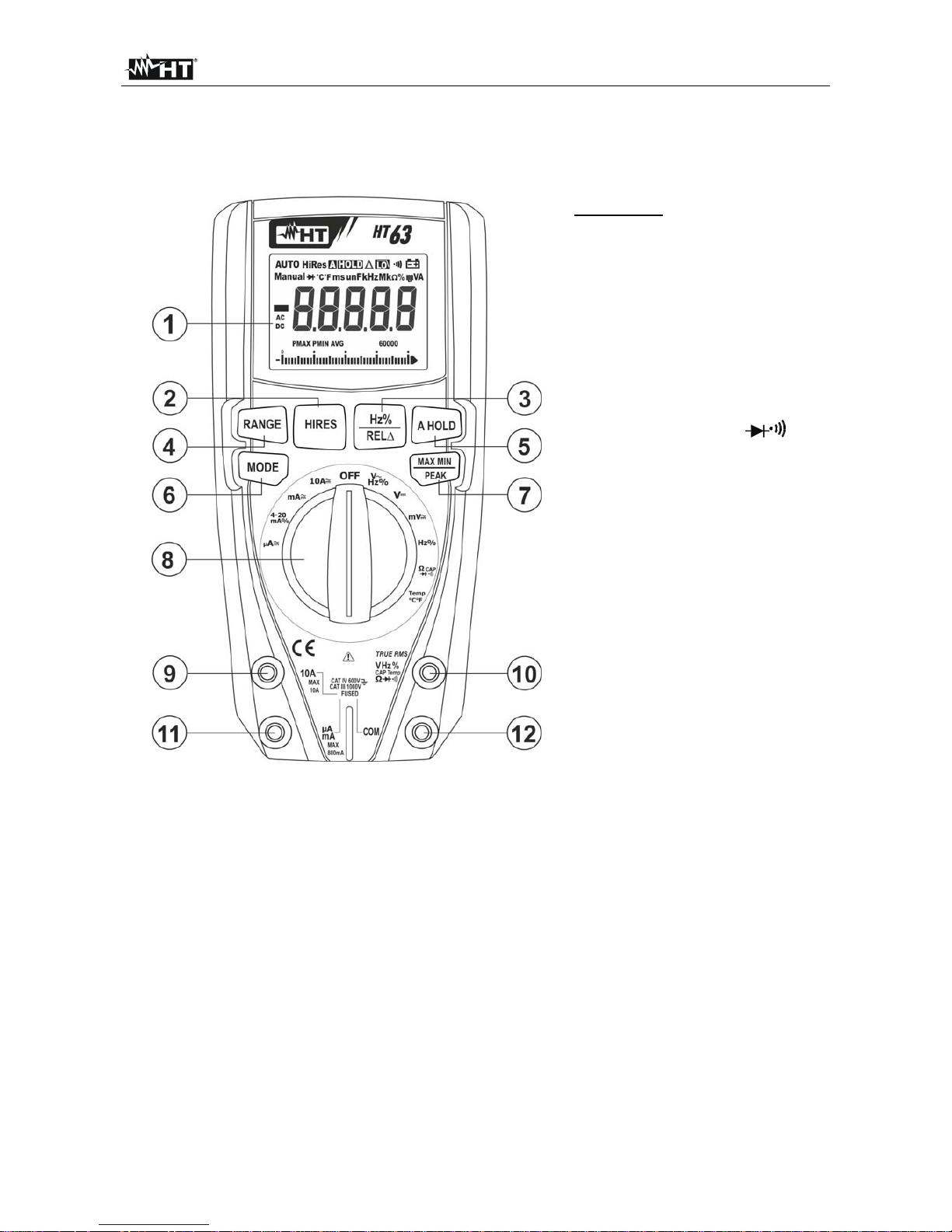
LEGENDA:
1. Display LCD
2. Tasto HIRES
3. Tasto Hz% / REL
4. Tasto RANGE
5. Tasto A HOLD
6. Tasto MODE
7. Tasto MAXMIN/PEAK
8. Selettore funzioni
9. Terminale di ingesso 10A
10. Terminale di ingresso
VHz%CAPTemp
11. Terminale di ingesso
mAA
12. Terminale di ingresso
COM
Fig. 1: Descrizione dello strumento
Page 12
HT63
IT - 7
4.2. DESCRIZIONE DEI TASTI FUNZIONE
4.2.1. Tasto A HOLD
La pressione del tasto A HOLD attiva il mantenimento del valore della grandezza
visualizzata a display. Conseguentemente alla pressione di tale tasto il messaggio "HOLD"
appare a display. Premere nuovamente il tasto HOLD per uscire dalla funzione.
Premere a lungo il tasto A HOLD al fine di attivare/disattivare la funzione di “AutoHOLD”. Il
messaggio “A HOLD” appare a display. Con questa funzione abilitata lo strumento
esegue il mantenimento del valore della grandezza aggiornandolo a display in modo
automatico quando un nuovo valore stabile è rilevato ed emettendo un suono durante
l’operazione. Tale funzione è utile in caso di segnali in ingresso aventi rapide oscillazioni.
4.2.2. Tasto RANGE
Premere il tasto RANGE per attivare il modo manuale disabilitando la funzione Autorange.
Il simbolo “AUTO” scompare nella parte alta sinistra del display. In modo manuale
premere il tasto RANGE per cambiare il campo di misura notando lo spostamento del
relativo punto decimale. Il tasto RANGE non è attivo nella nelle posizioni
, , CAP,
Hz%, Temp°C°F e 4-20mA%. In modo Autorange lo strumento seleziona il rapporto più
appropriato per effettuare la misura. Se una lettura è più alta del valore massimo
misurabile, l’indicazione "O.L" appare a display. Premere il tasto RANGE per oltre 1
secondo per uscire dal modo manuale e ripristinare il modo Autorange
4.2.3. Tasto MAX MIN/PEAK
Una pressione del tasto MAX MIN/PEAK attiva la rilevazione dei valori massimo (MAX),
minimo (MIN) e medio (AVG) della grandezza in esame. I valori sono continuamente
aggiornati e si presentano in maniera ciclica ad ogni nuova pressione del medesimo tasto.
Il tasto MAX MIN/PEAK non è operativo quando la funzione HOLD è attiva. Il tasto MAX
MIN/PEAK non è attivo nelle posizioni
, , CAP, Hz%, Temp°C°F e 4-20mA%
Premere a lungo il tasto MAX MIN/PEAK per oltre 1 secondo o agire sul selettore per
uscire dalla funzione.
Una pressione prolungata per 2 secondi del tasto MAX MIN/PEAK attiva la rilevazione dei
valori di picco Massimo e Minimo di Tensione e Corrente AC con tempo di risposta 1ms.
Entrambi i valori sono continuamente aggiornati e si presentano in maniera ciclica ad ogni
nuova pressione del medesimo tasto. Il display visualizza il simbolo associato alla
funzione selezionata: “PMAX” per il valore di picco massimo, “PMIN” per il valore di picco
minimo. E la funzione di Auto Power OFF è automaticamente disabilitata.
Premere il tasto MAX MIN/PEAK per oltre 2 secondi o agire sul selettore per uscire dalla
funzione
4.2.4. Tasto Hz%/REL
Premere il tasto Hz%/REL per la selezione delle misure di frequenza e duty cycle nelle
posizioni VHz%, 10AHz%, mA (AC), A (AC) e Hz% del selettore. Il campo di
frequenza è diverso nelle varie posizioni.
La pressione prolungata del tasto Hz%/REL consente l’attivazione della misura relativa.
Lo strumento azzera il display e salva il valore visualizzato quale valore di riferimento a cui
saranno riferite le successive misure. Il simbolo “” appare a display. Tale funzione non è
attiva nelle posizioni
, , Hz%, Temp°C°F e 4-20mA% . Premere nuovamente in
modo prolungato il tasto Hz%/REL per uscire dalla funzione
Page 13

HT63
IT - 8
4.2.5. Tasto MODE
La pressione del tasto MODE consente la selezione di una doppia funzione presente sul
selettore. In particolare esso è attivo nella posizione CAP per la selezione delle
misure di prova diodi, il test continuità, capacità e la misura di resistenza, nella posizione
Temp°C°F per la selezione della misura di temperatura in °C o °F e mA , A per la
selezione delle misure AC o DC.
Nella posizione VHz% la pressione del tasto MODE attiva/disattiva la funzione “ ” che
consente la lettura della tensione AC con un filtro passa basso in grado di ridurre gli effetti
di disturbo sul segnale. In questa condizione lo strumento passa in modalità Manuale.
4.2.6. Tasto HIRES
Premere il tasto HIRES al fine di attivare/disattivare il modo di funzionamento ad alta
risoluzione dello strumento ed il messaggio “HiRes” è mostrato a display. In questa
situazione lo strumento passa a 4½ cifre (60000 punti) per un maggiore dettaglio sulla
lettura dei dati. La funzione non è attiva nella posizione Temp°C°F e nella misura di
capacità. Premere nuovamente il tasto HIRES per tornare alla visualizzazione standard a
3½ cifre (6000 punti)
4.2.7. Disabilitazione funzione Autospegnimento
Al fine di preservare le batterie interne, lo strumento si spegne automaticamente dopo
circa 15 minuti di non utilizzo. Per disattivare l’autospegnimento operare come segue:
Spegnere lo strumento (OFF)
Tenendo premuto il tasto MODE accendere lo strumento ruotando il selettore. Il
messaggio “1OFF” compare a display
Spegnere e riaccendere lo strumento per abilitare nuovamente la funzione
Page 14
HT63
IT - 9
4.3. DESCRIZIONE DELLE FUNZIONI DEL SELETTORE
4.3.1. Misura di Tensione DC
ATTENZIONE
La massima tensione DC in ingresso è 1000V. Non misurare tensioni che
eccedono i limiti indicati in questo manuale. Il superamento dei limiti di
tensione potrebbe causare shock elettrici all’utilizzatore e danni allo
strumento.
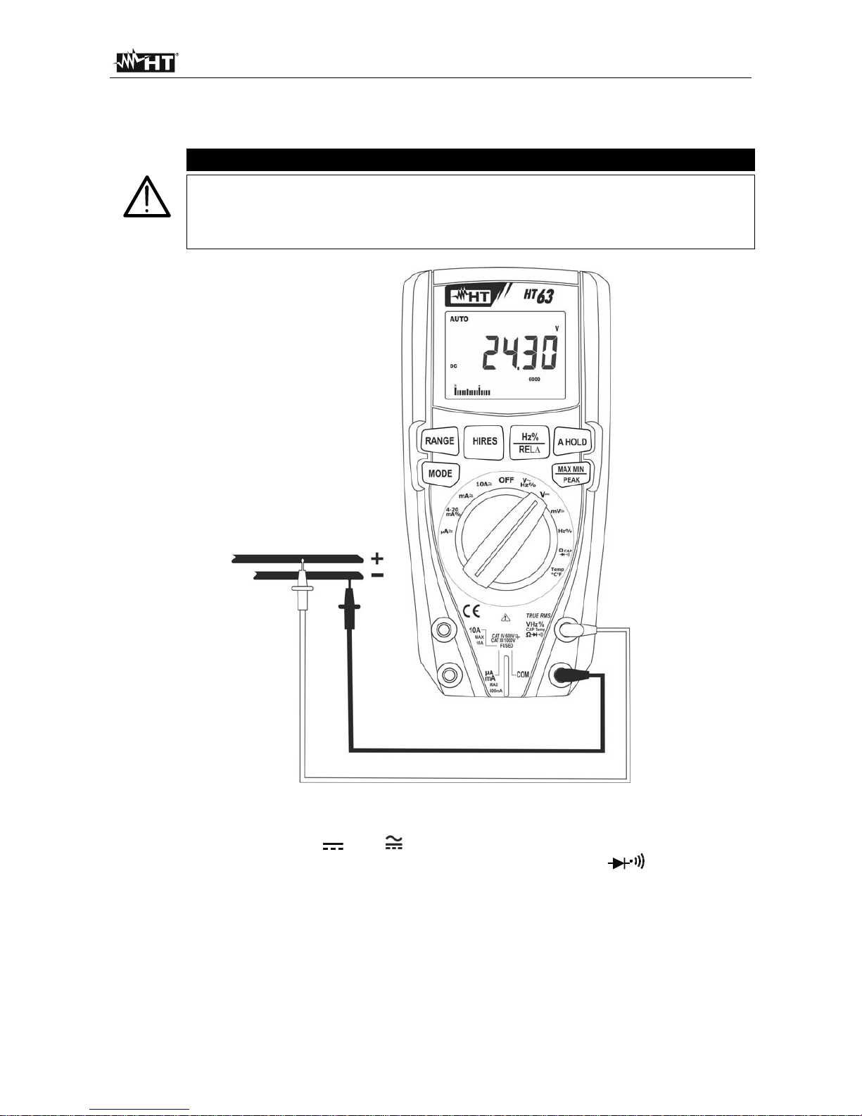
Fig. 2: Uso dello strumento per misura di Tensione DC
1. Selezionare la posizione V o mV
2. Inserire il cavo rosso nel terminale di ingresso VHz%CAPTemp e il cavo nero
nel terminale di ingresso COM
3. Posizionare il puntale rosso ed il puntale nero rispettivamente nei punti a potenziale
positivo e negativo del circuito in esame (vedere Fig. 2). Il valore della tensione è
mostrato a display
4. Se sul display è visualizzato il messaggio "O.L" selezionare una portata più elevata.
5. La visualizzazione del simbolo "-" sul display dello strumento indica che la tensione ha
verso opposto rispetto alla connessione di Fig. 2.
6. Per l’uso delle funzioni HOLD, RANGE, MAX MIN, REL e HIRES vedere il § 4.2
Page 15
HT63
IT - 10
4.3.2. Misura di Tensione AC
ATTENZIONE
La massima tensione AC in ingresso è 1000V. Non misurare tensioni che
eccedono i limiti indicati in questo manuale. Il superamento dei limiti di
tensione potrebbe causare shock elettrici all’utilizzatore e danni allo
strumento.
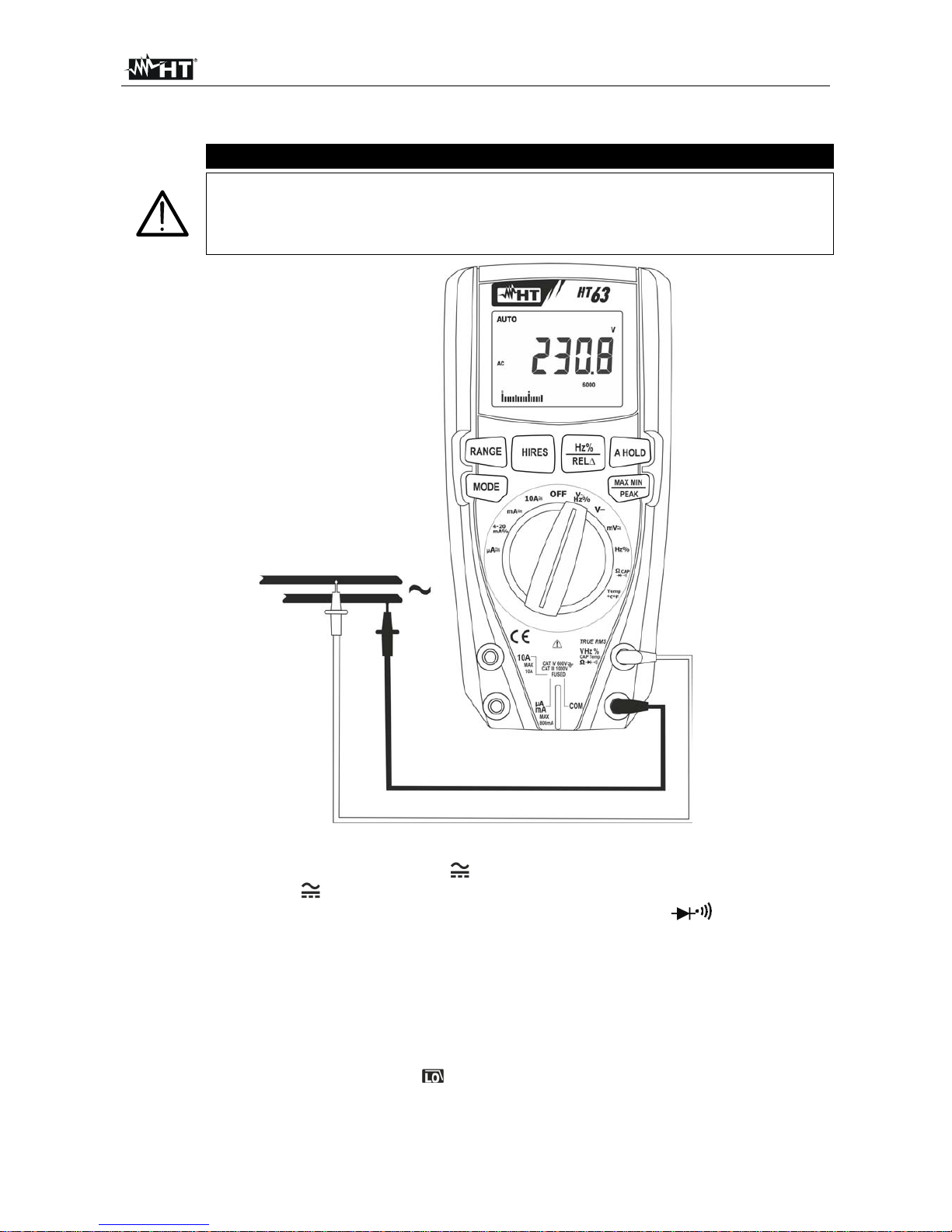
Fig. 3: Uso dello strumento per misura di Tensione AC
1. Selezionare la posizione VHz% o mV
2. Nella posizione mV premere il tasto MODE per visualizzare il simbolo “AC” a display
3. Inserire il cavo rosso nel terminale di ingresso VHz%CAPTemp e il cavo nero
nel terminale di ingresso COM
4. Posizionare il puntale rosso ed il puntale nero rispettivamente nei punti del circuito in
esame (vedere Fig. 3). Il valore della tensione è mostrato a display
5. Se sul display è visualizzato il messaggio "O.L" selezionare una portata più elevata
6. Premere il tasto Hz%/REL per selezionare le misure “Hz” o “ %” al fine di visualizzare i
valori della frequenza e del duty cycle della tensione in ingresso. La barra grafica non è
attiva in queste funzioni. Premere il tasto MODE per tornare alla misura di tensione e
attivare eventualmente la funzione
7. Per l’uso delle funzio ni HOLD, RANGE, MAX MIN, PEAK, e HIRES e REL vedere il §
4.2
Page 16
HT63
IT - 11
4.3.3. Misura di Frequenza e Duty Cycle
ATTENZIONE
La massima tensione AC in ingresso è 1000V. Non misurare tensioni che
eccedono i limiti indicati in questo manuale. Il superamento dei limiti di
tensione potrebbe causare shock elettrici all’utilizzatore e danni allo
strumento.
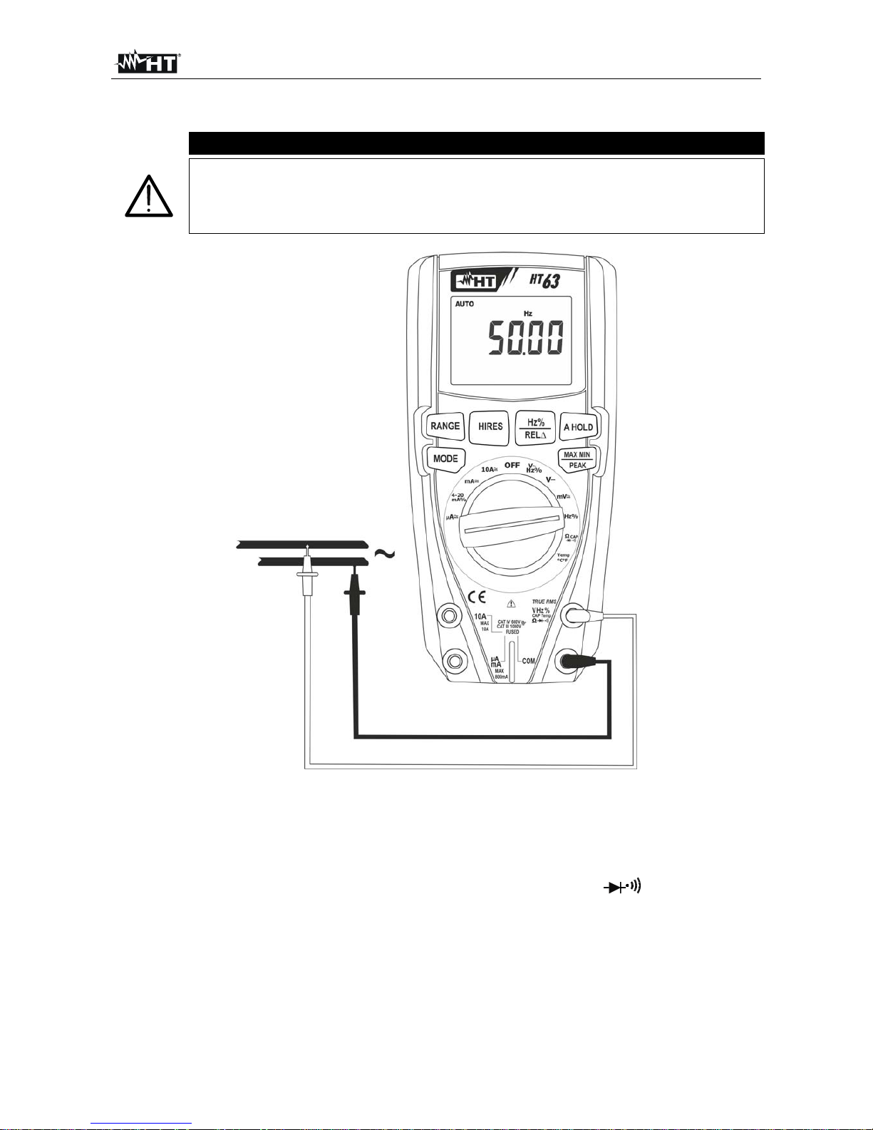
Fig. 4: Uso dello strumento per misura di Frequenza e Duty Cycle
1. Selezionare la posizione Hz%
2. Premere il tasto Hz% per selezionare le mis ure “Hz” o “%” al fine di visualizzare i valori
della frequenza e del duty cycle della tensione in ingresso
3. Inserire il cavo rosso nel terminale di ingresso VHz%CAPTemp (HT62) e il cavo
nero nel terminale di ingresso COM
4. Posizionare il puntale rosso ed il puntale nero rispettivamente nei punti del circuito in
esame (vedere Fig. 4). Il valore della frequenza (Hz) o duty cycle (%) è mostrato a
display. La barra grafica non è attiva in queste funzioni
5. Se sul display è visualizzato il messaggio "O.L" selezionare una portata più elevata
6. Per l’uso della funzione HOLD e HIRES vedere il § 4.2
Page 17
HT63
IT - 12
4.3.4. Misura di Resistenza e Test Continuità
ATTENZIONE
Prima di effettuare qualunque misura di resistenza accertarsi che il circuito
in esame non sia alimentato e che eventuali condensatori presenti siano
scarichi.
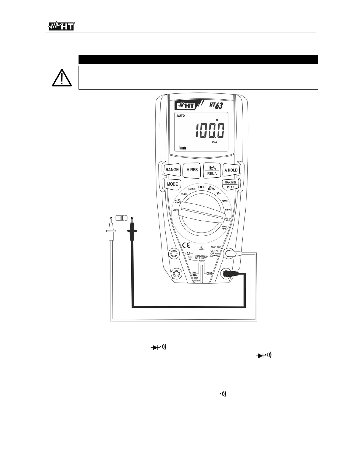
Fig. 5: Uso dello strumento per misura di Resistenza e Test Continuità
1. Selezionare la posizione CAP
2. Inserire il cavo rosso nel terminale di ingresso VHz%CAPTemp e il cavo nero
nel terminale di ingresso COM
3. Posizionare i puntali nei punti desiderati del circuito in esame (vedere Fig. 5). Il valore
della resistenza è visualizzato a display
4. Se sul display è visualizzato il messaggio "O.L" selezionare una portata più elevata
5. Premere il tasto MODE per selezionare la misura “ ” relativa al test continuità e
posizionare i puntali nei punti desiderati del circuito in esame
6. Il valore della resistenza (solo indicativo) è visualizzato sul display espresso in e lo
strumento emette un segnale acustico qualora il valore della resistenza risulti <35
7. Per l’uso delle funzioni HOLD, RANGE, MAX MIN, REL e HIRES vedere il § 4.2
Page 18

HT63
IT - 13
4.3.5. Prova Diodi
ATTENZIONE
Prima di effettuare qualunque misura di resistenza accertarsi che il circuito
in esame non sia alimentato e che eventuali condensatori presenti siano
scarichi.
Fig. 6: Uso dello strumento per la Prova Diodi
1. Selezionare la posizione CAP
2. Premere il tasto MODE per selezionare la misura “ ”
3. Inserire il cavo rosso nel terminale di ingresso VHz%CAPTemp e il cavo nero
nel terminale di ingresso COM
4. Posizionare i puntali ai capi del diodo in esame (vedere Fig. 6) rispettando le polarità
indicate. Il valore della tensione di soglia in polarizzazione diretta è mostrato a display
5. Se il valore della tensione di soglia è 0mV la giunzione P-N del diodo è in corto circuito
6. Se lo strumento visualizza il messaggio "O.L" i terminali del diodo sono invertiti rispetto
a quanto indicato in Fig. 6 oppure la giunzione P-N del diodo è danneggiata
7. Per l’uso delle funzioni HOLD e HIRES vedere il § 4.2
Page 19

HT63
IT - 14
4.3.6. Misura di Capacità
ATTENZIONE
Prima di eseguire misure di capacità su circuiti o condensatori, rimuovere
l’alimentazione al circuito sotto esame e lasciare scaricare tutte le capacità
presenti in esso. Nel collegamento tra il multimetro e la capacità sotto
esame rispettare la corretta polarità (quando richiesto).
Fig. 7: Uso dello strumento per misura di Capacità
1. Selezionare la posizione CAP
2. Premere il tasto MODE fino a visualizzare il simbolo “nF” a display
3. Inserire il cavo rosso nel terminale di ingresso VHz%CAPTemp e il cavo nero
nel terminale di ingresso COM
4. Premere il tasto REL/ prima di eseguire la misura
5. Posizionare i puntali ai capi del condensatore in esame rispettando eventualmente le
polarità positive (cavo rosso) e negative (cavo nero) (vedere Fig. 7). Il valore della
capacità è mostrato a display. La barra grafica non è attiva in questa funzione
6. Il messaggio "O.L." indica che il valore di capacità eccede il valore massimo
misurabile
7. Per l’uso delle funzioni HOLD, e REL vedere il § 4.2
Page 20
HT63
IT - 15
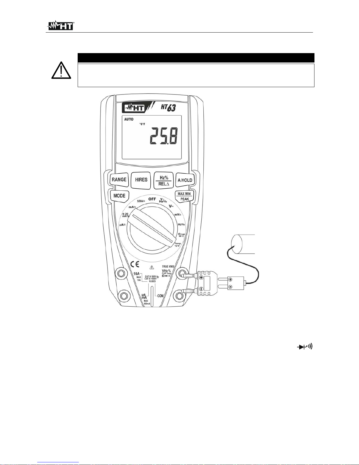
4.3.7. Misura di Temperatura con sonda K
ATTENZIONE
Prima di effettuare qualunque misura di temperatura accertarsi che il
circuito in esame non sia alimentato e che eventuali condensatori presenti
siano scarichi.
Fig. 8: Uso dello strumento per misura di Temperatura
1. Selezionare la posizione Temp°C°F
2. Premere il tasto MODE fino a visualizzare il simbolo “°C” o “°F” a display
3. Inserire l’adattatore in dotazione nei terminali di ingresso VHz%CAPTemp
(polarità +) e COM (polarità -) (vedere Fig. 8)
4. Collegare la sonda a filo tipo K in dotazione o la termocoppia tipo K opzionale (vedere
§ 6.3.2) allo strumento tramite l’adattatore rispettando le polarità positiva e negativa
presenti su di esso. Il valore della temperatura è mostrato a display. La barra grafica
non è attiva in questa funzione
5. Il messaggio "O.L." indica che il valore di temperatura eccede il valore massimo
misurabile
6. Per l’uso della funzione HOLD vedere il § 4.2
Page 21
HT63
IT - 16
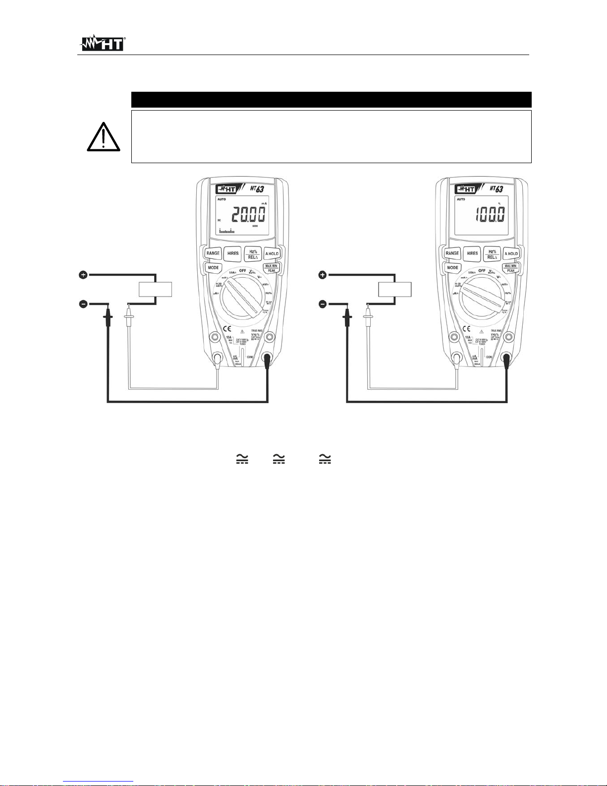
4.3.8. Misura di Corrente DC e lettura 4-20mA%
ATTENZIONE
La massima corrente DC in ingresso è 10A (ingresso 10A) oppure 600mA
(ingresso mAA). Non misurare correnti che eccedono i limiti indicati in
questo manuale. Il superamento dei limiti di corrente potrebbe causare
shock elettrici all’utilizzatore e danni allo strumento.
Fig. 9: Uso dello strumento per misura di Corrente DC e lettura 4-20mA%
1. Togliere alimentazione al circuito in esame.
2. Selez ionare la posizione A , mA o 10A per la misura di corrente DC oppure la
posizione 4-20mA% per la lettura 4-20mA%
3. Inserire il cavo rosso nel terminale di ingresso 10A oppure nel terminale di ingresso
mAA e il cavo nero nel terminale di ingresso COM
4. Collegare il puntale rosso ed il puntale nero in serie al circuito di cui si vuole misurare
la corrente rispettando la polarità ed il verso della corrente (vedere Fig. 9)
5. Alimentare il circuito in esame
6. Il valore della corrente DC (vedere Fig. 9 – parte sinistra) è visualizzato a display
7. Il valore della lettura 4-20mA% (0mA = -25%, 4mA = 0%, 20mA = 100% e 24mA =
125%) (vedere Fig. 9 – parte destra) è visualizzato a display. La barra grafica non è
attiva in questa funzione
8. Se sul display è visualizzato il messaggio "O.L" si è raggiunto il valore massimo
misurabile
9. La visualiz zazione del simbolo "-" sul display dello strumento indica che la corrente ha
verso opposto rispetto alla connessione di Fig. 9
10. Per l’uso delle funzioni HOLD, RANGE, MAX MIN, REL e HIRES vedere il § 4.2
Page 22
HT63
IT - 17
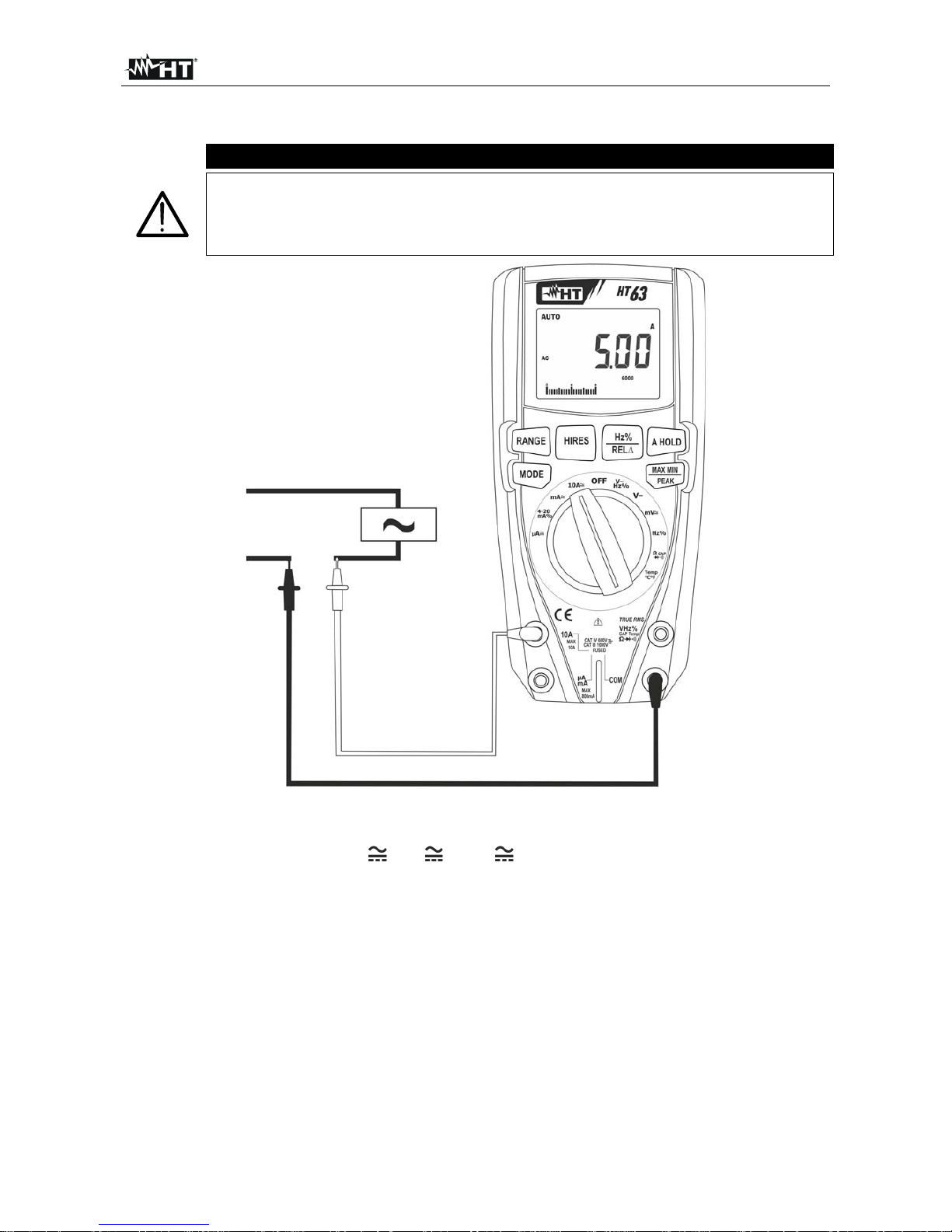
4.3.9. Misura di Corrente AC
ATTENZIONE
La massima corrente AC in ingresso è 10A (ingresso 10A) oppure 600mA
(ingresso mAA). Non misurare correnti che eccedono i limiti indicati in
questo manuale. Il superamento dei limiti di corrente potrebbe causare
shock elettrici all’utilizzatore e danni allo strumento.
Fig. 10: Uso dello strumento per misura di Corrente AC
1. Togliere alimentazione al circuito in esame.
2. Selezionare la posizione A , mA o 10A
3. Premere il tasto MODE per selezionare la misura “AC”
4. Inserire il cavo rosso nel terminale di ingresso 10A oppure nel terminale di ingresso
mAA e il cavo nero nel terminale di ingresso COM
5. Collegare il puntale rosso ed il puntale nero in serie al circuito di cui si vuole misurare
la corrente (vedere Fig. 10)
6. Alimentare il circuito in esame. Il valore della corrente è visualizzato a display.
7. Se sul display è visualizzato il messaggio "O.L" si è raggiunto il valore massimo
misurabile
8. Premere il tasto Hz%/REL per selezionare le misure “Hz” o “%” al fine di visualizzare i
valori della frequenza e del duty cycle della corrente in ingresso. La barra grafica non è
attiva in queste funzioni
9. Per l’uso delle funzioni HOLD, RANGE, MAX MIN, PEAK, REL e HIRES vedere il §
4.2
Page 23
HT63
IT - 18
5. MANUTENZIONE
ATTENZIONE
Solo tecnici qualificati possono effettuare le operazioni di manutenzione.
Prima di effettuare la manutenzione rimuovere tutti i cavi dai terminali di
ingresso
Non utilizzare lo strumento in ambienti caratterizzati da elevato tasso di
umidità o temperatura elevata. Non esporre direttamente alla luce del sole
Spegnere sempre lo strumento dopo l’utilizzo. Se si prevede di non
utilizzarlo per un lungo periodo rimuovere la batteria per evitare fuoruscite
di liquidi da parte di quest’ultima che possano danneggiare i circuiti interni
dello strumento
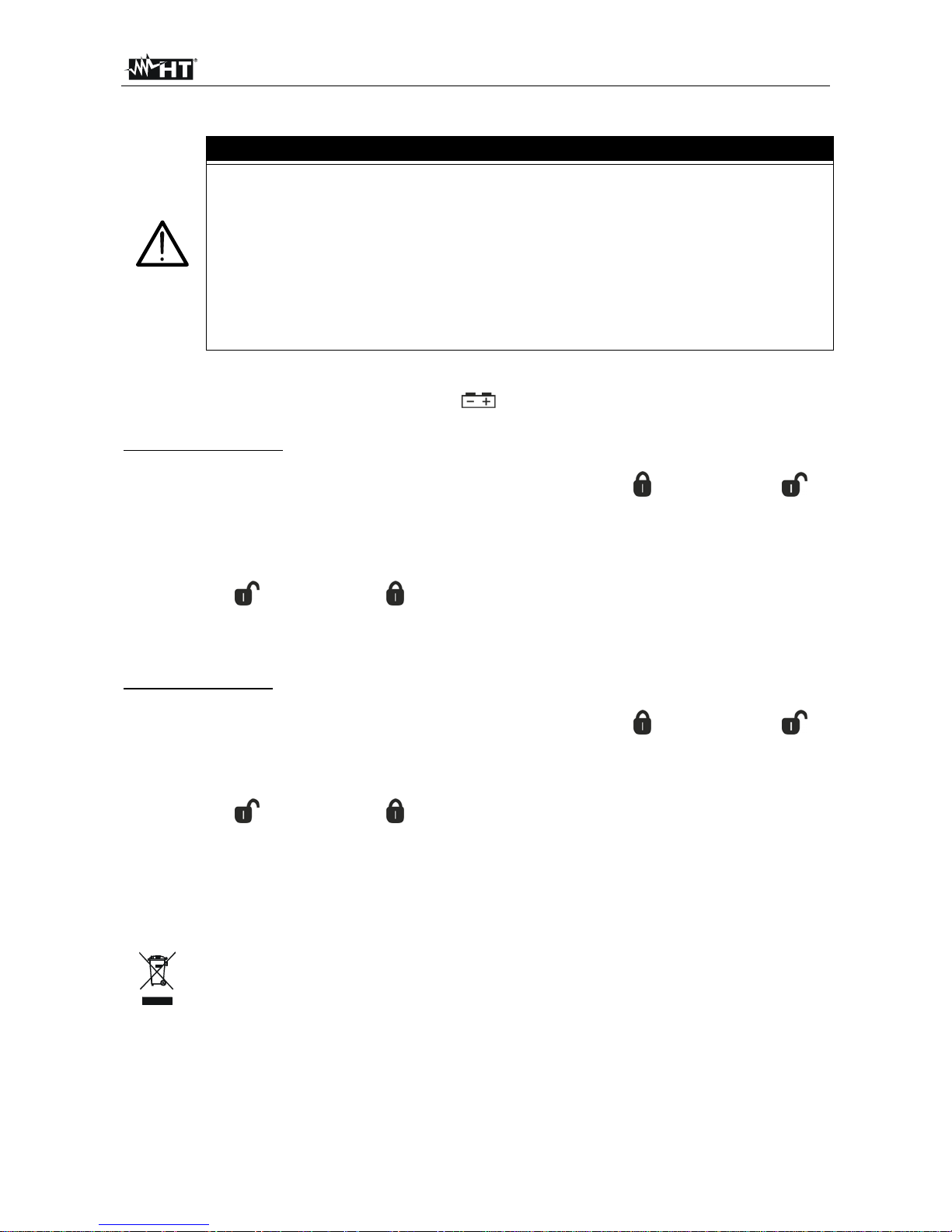
5.1. SOSTITUZIONE BATTERIE E FUSIBILI INTERNI
Quando sul display LCD appare il simbolo " " occorre sostituire la batteria.
Sostituzione batteria
1. Posizionare il selettore in posizione OFF e rimuovere i cavi dai terminali di ingresso
2. Ruotare la vite di fissaggio del vano batterie dalla posizione “ ” alla posizione “ ” e
rimuovere lo stesso
3. Rimuovere la batteria e inserire nel vano la nuova batteria dello stesso tipo (vedere §
6.1.2) rispettando le polarità indicate
4. Riposizionare il vano batterie e ruotare la vite di fissaggio del vano batterie dalla
posizione “ ” alla posizione “ ”
5. Non disperdere nell’ambiente le batterie utilizzate. Usare gli appositi conten itori per lo
smaltimento
Sostituzione fusibili
1. Posizionare il selettore in posizione OFF e rimuovere i cavi dai terminali di ingresso
2. Ruotare la vite di fissaggio del vano batterie dalla posizione “
” alla posizione “ ” e
rimuovere lo stesso
3. Rimuovere il fusibile danneggiato e inserirne uno dello stesso tipo (vedere § 6.1.2)
4. Riposizionare il vano batterie e ruotare la vite di fissaggio del vano batterie dalla
posizione “ ” alla posizione “ ”
5.2. PULIZIA DELLO STRUMENTO
Per la pulizia dello strumento utilizzare un panno morbido e asciutto. Non usare mai panni
umidi, solventi, acqua, ecc.
5.3. FINE VITA
ATTENZIONE: il simbolo riportato sullo strumento indica che l'apparecchiatura
ed i suoi accessori devono essere raccolti separatamente e trattati in modo
corretto.
Page 24
HT63
IT - 19
6. SPECIFICHE TECNICHE
6.1. CARATTERISTICHE TECNICHE
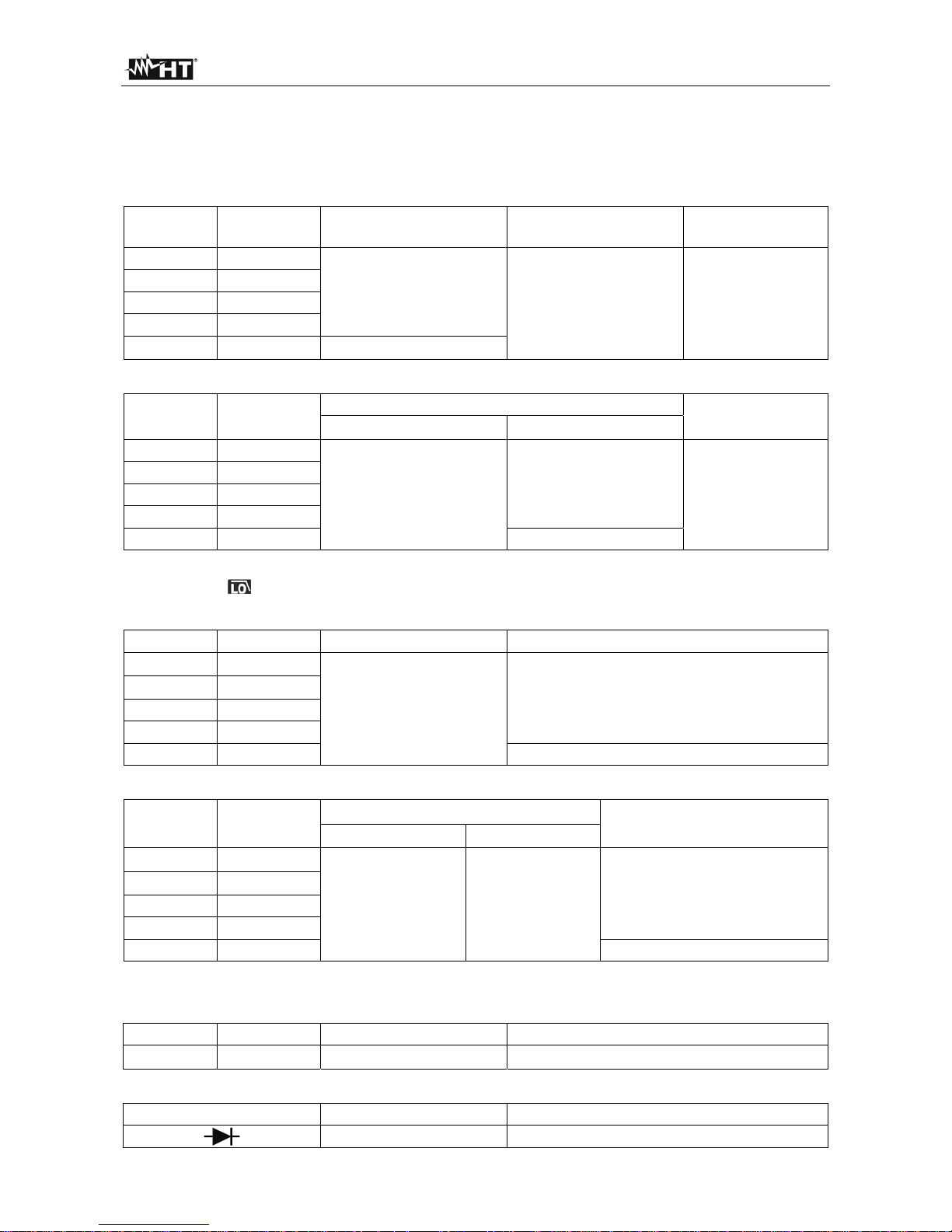
Incertezza calcolata come [%lettura + (num. cifre*risoluzione)] a 18°C 28°C <75%HR
Tensione DC
Campo Risoluzione Incertezza Impedenza d’ingresso
Protezione contro i
sovraccarichi
600.0mV 0.1mV
(0.9%lettura + 5cifre)
>10M
1000VDC/ACrms
6.000V 0.001V
60.00V 0.01V
600.0V 0.1V
1000V 1V
(1.2%lettura + 5cifre)
Tensione AC TRMS
Campo Risoluzione
Incertezza (*)
Protezione contro i
sovraccarichi
(50Hz1kHz) (1kHz5kHz)
600.0mV 0.1mV
(1.0%lettura + 5cifre)
(3.0%lettura + 5cifre)
1000VDC/ACrms
6.000V 0.001V
60.00V 0.01V
600.0V 0.1V
1000V 1V Non specificata
(*) Incertezza specificata dal 5% al 100% del campo di misura, Impedenza di ingresso: > 10M
Incertezza funzione PEAK: 10%lettura; Tempo di risposta funzione PEAK: 1ms
Incertezza funzione
: (1.5%lettura + 5cifre) (f 60Hz), (3.0%lettura + 5cifre) (60Hz f 1kHz), non specificata (f: 1 5kHz)
Corrente DC
Ca m p o Risoluzione Incertezza Pr o t e z i o ne c o n t r o i s o v r accarichi
600.0A 0.1A
(1.5%lettura + 5cifre)
Fusibile rapido 800mA/1000V
6000A 1A
60.00mA 0.01mA
600.0mA 0.1mA
10.00A 0.01A Fusibile rapido 10A/1000V
Corrente AC TRMS
Campo Risoluzione
Incertezza (*)
Protezione contro i
sovraccarichi
(50Hz1kHz) (1kHz5kHz)
600.0A 0.1A
(2.5%lettura + 5cifre)
(3.5%lettura+5cifre)
Fusibile rapido 800mA/1000V
6000A 1A
60.00mA 0.01mA
600.0mA 0.1mA
10.00A 0.01A Fusibile rapido 10A/1000V
(*) Incertezza specificata dal 5% al 100% del campo di misura
Incertezza funzione PEAK: 10%lettura
Lettura 4-20mA%
Campo Risoluzione Incertezza Corrispondenza
-25%125%
0.1%
(50cifre)
0mA=-25%, 4mA=0%, 20mA=100%, 24mA=125%
Prova Diodi
Funzione Corrente di prova Max Tensione a circuito aperto
<1.5mA 2.8VDC
Page 25
HT63
IT - 20
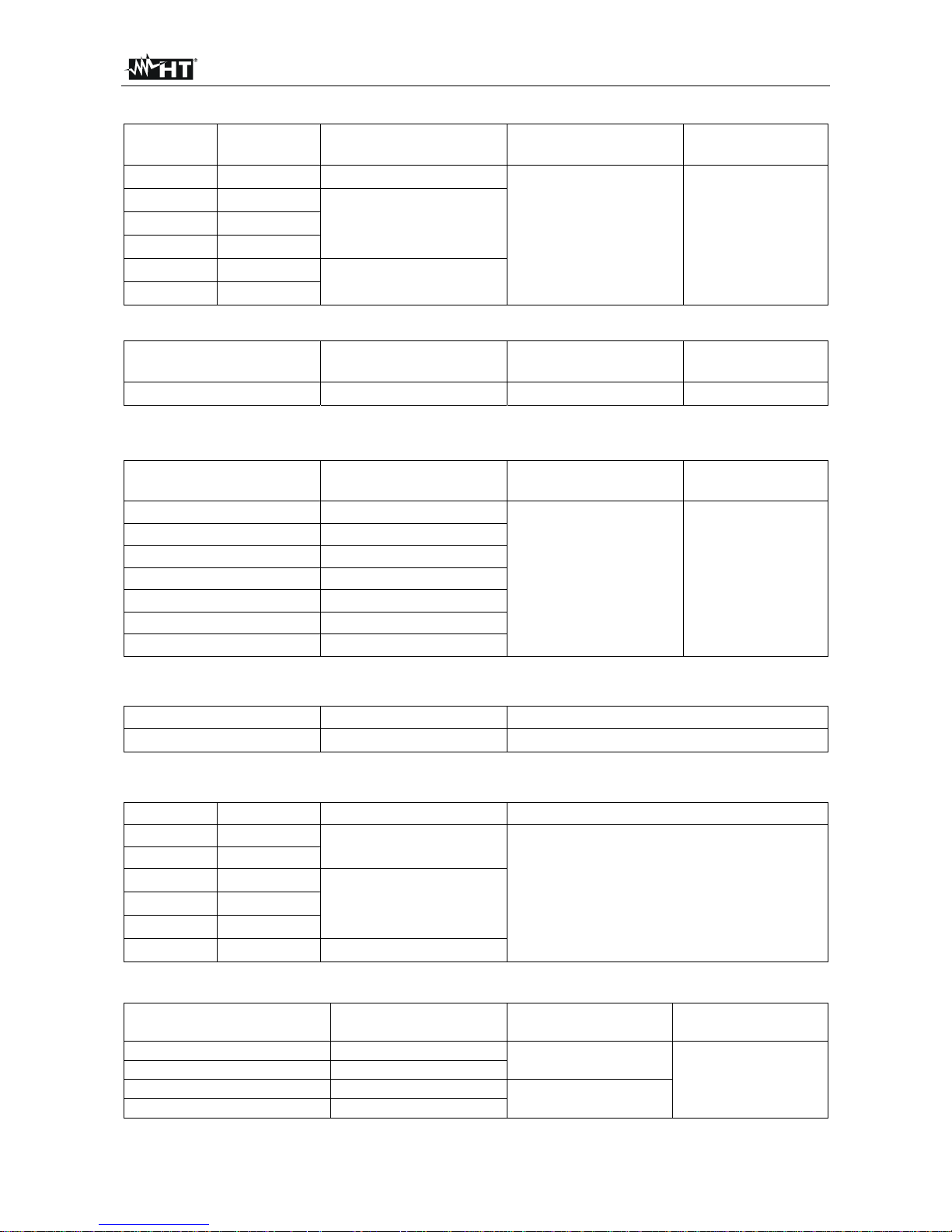
Resistenza e Test Continuità
Campo Risoluzione Incertezza Buzzer
Protezione contro i
sovraccarichi
600.0 0.1 (2.0%lettura + 9cifre)
<35
1000VDC/ACrms
6.000k 0.001k
(1.2%lettura + 5cifre)
60.00k 0.01k
600.0k 0.1k
6.000M 0.001M
(2.0%lettura + 10cifre)
60.00M 0.01M
Frequenza (circuiti elettrici)
Campo Risoluzione Incertezza
Protezione contro i
sovraccarichi
40.00Hz 10kHz
0.01Hz
(0.5%lettura)
1000VDC/ACrms
Sensibilità: 15Vrms
Frequenza (circuiti elettronici)
Campo Risoluzione Incertezza
Protezione contro i
sovraccarichi
60.00Hz 0.01Hz
(1.0%lettura + 2cifre)
1000VDC/ACrms
600.0Hz 0.1Hz
6.000kHz 0.001kHz
60.00kHz 0.01kHz
600.0kHz 0.1kHz
6.000MHz 0.001MHz
10.00MHz 0.01MHz
Sensibilità: >2.0Vrms (@ 20% 80% duty cycle) e f<100kHz; >5Vrms (@ 20% 80% duty cycle) e f>100kHz
Duty Cycle (ciclo di lavoro)
Campo Risoluzione Incertezza
0.1% 99.9%
0.1%
(1.2%lettura + 2cifre)
Campo frequenza impulso: 5Hz 10kHz, Ampiezza impulso: ±5V (100s 100ms)
Capacità
Ca m p o Risoluzione Incertezza Pr o t e z i o ne c o n t r o i s o v r accarichi
60.00nF 0.01nF
(3.5%lettura + 10cifre)
1000VDC/ACrms
600.0nF 0.1nF
6.000F 0.001F
(2.5%lettura + 10cifre)
60.00F 0.01F
600.0F 0.1F
6.000mF 0.001mF
(3.5%lettura + 10cifre)
Temperatura con sonda K
Campo Risoluzione Incertezza (*)
Protezione contro
i Sovraccarichi
-40.0°C ÷ 600.0°C 0.1°C
(2.0%lettura + 3°C)
1000VDC/ACrms
600°C ÷ 760°C 1°C
-58.0°F ÷ 600.0°F 0.1°F
(2.0%lettura+ 5.5°F)
600°F ÷ 1400°F 1°F
(*) Incertezza strumento senza sonda
Page 26
HT63
IT - 21
6.1.1. Norme di riferimento
Sicurezza: IEC/EN61010-1
EMC: IEC/EN 61326-1
Isolamento: doppio isolamento
Livello di Inquinamento: 2
Categoria di sovratensione: CAT IV 600V, CAT III 1000V
Altitudine max di utilizzo: 2000m
6.1.2. Caratteristiche generali
Caratteristiche meccaniche
Dimensioni (L x La x H): 175 x 85 x 55mm
Peso (batterie incluse): 360g
Alimentazione
Tipo batteria: 4x1.5V batterie tipo AAA IEC LR03
Indicazione batteria scarica: simbolo " " a display
Autospegnimento: dopo 15min di non utilizzo (disabilitabile)
Fusibili: F10A/1000V, 10 x 38mm (ingresso 10A)
F800mA/1000V, 6 x 32mm (ingresso mAA)
Display
Conversione: TRMS
Caratteristiche: 3½ LCD, 6000 punti, segno, punto decimale
4½ LCD, 60000 punti, segno, punto decimale
backlight e bargraph
Frequenza campionamento: 3 volte/s
6.2. AMBIENTE
6.2.1. Condizioni ambientali di utilizzo
Temperatura di riferimento: 18°C 28°C
Temperatura di utilizzo: 5°C ÷ 40°C
Umidità relativa ammessa: <80%HR
Temperatura di conservazione: -20° ÷ 60°C
Umidità di conservazione: <80%HR
Questo strumento è conforme ai requisiti della Direttiva Europea sulla bassa
tensione 2006/95/CE (LVD) e della direttiva EMC 2004/108/CE
Questo strumento è conforme ai requisiti della direttiva europea 2011/65/CE (RoHS)
e della direttiva europea 2012/19/CE (WEEE)
6.3. ACCESSORI
6.3.1. Accessori in dotazione
Coppia di puntali
Adattatore + sonda a filo tipo K
Batterie
Borsa per trasporto
Manuale d’uso
6.3.2. Accessori opzionali
Coppia di puntali Cod. KIT4000A
Sonda tipo K per temperatura di aria e gas Cod. TK107
Sonda tipo K per temperatura di sostanze semisolide Cod. TK108
Sonda tipo K per temperatura di liquidi Cod. TK109
Sonda tipo K per temperatura di superfici Cod. TK110
Sonda tipo K per temperatura di superfici con punta a 90° Cod. TK111
Page 27

HT63
IT - 22
7. ASSISTENZA
7.1. CONDIZIONI DI GARANZIA
Questo strumento è garantito contro ogni difetto di materiale e fabbricazione, in conformità
con le condizioni generali di vendita. Durante il periodo di garanzia, le parti difettose
possono essere sostituite, ma il costruttore si riserva il diritto di riparare ovvero sostituire il
prodotto.
Qualora lo strumento debba essere restituito al servizio post - vendita o ad un rivenditore,
il trasporto è a carico del Cliente. La spedizione dovrà, in ogni caso, essere
preventivamente concordata. Allegata alla spedizione deve essere sempre inserita una
nota esplicativa circa le motivazioni dell’invio dello strumento. Per la spedizione utilizzare
solo l’imballo originale. Ogni danno causato dall’utilizzo di imballaggi non originali verrà
addebitato al Cliente. Il costruttore declina ogni responsabilità per danni causati a persone
o oggetti.
La garanzia non è applicata nei seguenti casi:
Riparazione e/o sostituzione accessori e batteria (non coperti da garanzia).
Riparazioni che si rendono necessarie a causa di un errato utilizzo dello strumento o
del suo utilizzo con apparecchiature non compatibili.
Riparazioni che si rendono necessarie a causa di un imballaggio non adeguato.
Riparaz ioni che si rendono necessarie a causa di interventi eseguiti da personale non
autorizzato.
Modifiche apportate allo strumento senza esplicita autorizzazione del costruttore.
Utilizzo non contemplato nelle specifiche dello strumento o nel manuale d’uso.
Il contenuto del presente manuale non può essere riprodotto in alcuna forma senza
l’autorizzazione del costruttore.
I nostri prodotti sono brevettati e i marchi depositati. Il costruttore si riserva il diritto
di apportare modifiche alle specifiche ed ai prezzi se ciò è dovuto a miglioramenti
tecnologici.
7.2. ASSISTENZA
Se lo strumento non funziona correttamente, prima di contattare il Servizio di Assistenza,
controllare lo stato della batteria e dei cavi e sostituirli se necessario. Se lo strumento
continua a manifestare malfunzionamenti controllare se la procedura di utilizzo dello
stesso è conforme a quanto indicato nel presente manuale. Qualora lo strumento debba
essere restituito al servizio post - vendita o ad un rivenditore, il trasporto è a carico del
Cliente. La spedizione dovrà, in ogni caso, essere preventivamente concordata. Allegata
alla spedizione deve essere sempre inserita una nota esplicativa circa le motivazioni
dell’invio dello strumento. Per la spedizione utilizzare solo l’imballaggio originale; ogni
danno causato dall’utilizzo di imballaggi non originali verrà addebitato al Cliente.
Page 28

Page 29

Copyright HT ITALIA 2016 Version EN 1.02 - 25/01/2016
ENGLISH
User manual
Page 30

HT63
EN - 1
Table of contents:
1. PRECAUTIONS AND SAFETY MEASURES ............................................................... 2
1.1. Preliminary instructions ..................................................................................................... 2
1.2. During use ......................................................................................................................... 3
1.3. After use ............................................................................................................................ 3
1.4. Definition of Measurement (Overvoltage) category ........................................................... 3
2. GENERAL DESCRIPTION ........................................................................................... 4
2.1. Measuring average values andTRMS values .................................................................... 4
2.2. Definition of true root mean square value and Crest factor ............................................... 4
3. PREPARATION FOR USE ........................................................................................... 5
3.1. Initial checks ...................................................................................................................... 5
3.2. Instrument power supply ................................................................................................... 5
3.3. Calibration ......................................................................................................................... 5
3.4. Storage .............................................................................................................................. 5
4. OPERATING INSTRUCTIONS ..................................................................................... 6
4.1. Description of the instrument ............................................................................................. 6
4.1.1. Description of the controls .......................................................................................................... 6
4.2. Description of function keys .............................................................................................. 7
4.2.1. A HOLD key ................................................................................................................................ 7
4.2.2. RANGE key ................................................................................................................................ 7
4.2.3. MAX MIN/PEAK key ................................................................................................................... 7
4.2.4. Hz%/REL key ........................................................................................................................... 7
4.2.5. MODE key .................................................................................................................................. 8
4.2.6. HIRES key .................................................................................................................................. 8
4.2.7. Disabling the Auto Power Off function ........................................................................................ 8
4.3. Description of rotary switch functions ................................................................................ 9
4.3.1. DC Voltage measurement .......................................................................................................... 9
4.3.2. AC Voltage measurement ........................................................................................................ 10
4.3.3. Frequency and Duty Cycle measurement ................................................................................ 11
4.3.4. Resistance measurement and Continuity test .......................................................................... 12
4.3.5. Diode test .................................................................................................................................. 13
4.3.6. Capacitance measurement ....................................................................................................... 14
4.3.7. Temperature measurement with K-type probe ......................................................................... 15
4.3.8. DC Current measurement and e 4-20mA% reading ................................................................ 16
4.3.9. AC Current measurement ......................................................................................................... 17
5. MAINTENANCE ......................................................................................................... 18
5.1. Replacing the batteries and the internal fuses ................................................................ 18
5.2. Cleaning the instrument .................................................................................................. 18
5.3. End of life ........................................................................................................................ 18
6. TECHNICAL SPECIFICATIONS ................................................................................ 19
6.1. Technical characteristics ................................................................................................. 19
6.1.1. Reference standards ................................................................................................................ 21
6.1.2. General characteristics ............................................................................................................. 21
6.2. Environment .................................................................................................................... 21
6.2.1. Environmental conditions for use ............................................................................................. 21
6.3. Accessories ..................................................................................................................... 21
6.3.1. Accessories provided ............................................................................................................... 21
6.3.2. Optional accessories ................................................................................................................ 21
7. ASSISTANCE ............................................................................................................. 22
7.1. Warranty conditions ......................................................................................................... 22
7.2. Assistance ....................................................................................................................... 22
Page 31

HT63
EN - 2
1. PRECAUTIONS AND SAFETY MEASURES
The instrument has been designed in compliance with directive IEC/EN61010-1 relevant to
electronic measuring instruments. For your safety and in order to prevent damaging the
instrument, please carefully follow the procedures described in this manual and read all
notes preceded by symbol with the utmost attention.
Before and after carrying out measurements, carefully observe the following instructions:
Do not carry out any measurement in humid environments.
Do not carry out any measurements in case gas, explosive materials or flammables are
present, or in dusty environments.
Avoid any contact with the circuit being measured if no measurements are being
carried out.
Avoid any contact with exposed metal parts, with unused measuring probes, circuits,
etc.
Do not carry out any measurement in case you find anomalies in the instrument such
as deformation, breaks, substance leaks, absence of display on the screen, etc.
Pay special attention when measuring voltages higher than 20V, since a risk of
electrical shock exists.
In this manual, and on the instrument, the following symbols are used:
Warning: observe the instructions given in this manual; improper use could
damage the instrument or its components.
Double-insulated meter
AC voltage or current
DC voltage or current
Connection to earth
1.1. PRELIMINARY INSTRUCTIONS
This instrument has been designed for use in environments of pollution degree 2.
It can be used for VOLTAGE and CURRENT measurements on installations with CAT
IV 600V and CAT III 1000V.
We recommend following the normal safety rules devised by the procedures for
carrying out operations on live systems and using the prescribed PPE to protect the
user against dangerous currents and the instrument against incorrect use.
In case the lack of indication of the presence of voltage may represent a danger for the
operator, always carry out a continuity measurement before carrying out the
measurement on the live system, in order to confirm the correct connection and
condition of the leads.
Only the leads supplied with the instrument guarantee compliance with the safety
standards. They must be in good conditions and be replaced with identical models,
when necessary.
Do not test circuits exceeding the specified voltage limits.
Do not perform any test under environmental conditions exceeding the limits indicated
in § 6.2.1.
Check that the battery is correctly inserted.
Make sure that the LCD display and the rotary switch indicate the same function.
Page 32

HT63
EN - 3
1.2. DURING USE
Please carefully read the following recommendations and instructions:
CAUTION
Failure to comply with the caution notes and/or instructions may damage
the instrument and/or its components or be a source of danger for the
operator.
Before activating the rotary switch, disconnect the test leads from the circuit being
measured.
When the instrument is connected to the circuit being measured, do not touch any
unused terminal.
Do not measure resistance in case external voltages are present; even if the
instrument is protected, an excessive voltage may cause malfunction.
While measuring, if the value or the sign of the quantity being measured remain
unchanged, check if the HOLD function is enabled.
1.3. AFTER USE
When measurement is complete, set the rotary switch to OFF to turn off the instrument.
If the instrument is not to be used for a long time, remove the batteries.
1.4. DEFINITION OF MEASUREMENT (OVERVOLTAGE) CATEGORY
Standard “IEC/EN61010-1: Safety requirements for electrical equipment for measurement,
control and laboratory use, Part 1: General requirements”, defines what measurement
category, commonly called overvoltage category, is. § 6.7.4: Measured circuits, reads:
(OMISSIS)
Circuits are divided into the following measurement categories:
Measurement category IV is for measurements performed at the source of the low-
voltage installation.
Examples are electricity meters and measurements on primary overcurrent protection
devices and ripple control units.
Measurement category III is for measurements performed on installations inside
buildings.
Examples are measurements on distribution boards, circuit breakers, wiring, including
cables, bus-bars, junction boxes, switches, socket-outlets in the fixed installation, and
equipment for industrial use and some other equipment, for example, stationary motors
with permanent connection to fixed installation.
Measurement category II is for measurements performed on circuits directly
connected to the low-voltage installation.
Examples are measurements on household appliances, portable tools and similar
equipment.
Measurement category I is for measurements performed on circuits not directly
connected to MAINS.
Examples are measurements on circuits not derived from MAINS, and specially
protected (internal) MAINS-derived circuits. In the latter case, transient stresses are
variable; for that reason, the standard requires that the transient withstand capability of
the equipment is made known to the user.
Page 33

HT63
EN - 4
2. GENERAL DESCRIPTION
The instrument carries out the following measurements:
DC Voltage
AC TRMS Voltage
DC Current
4-20mA% display
AC TRMS Current
Resistance and Continuity test
Diode test
Capacity
Current and voltage frequency
Duty Cycle
Temperature with K-type probe
Each of these functions can be selected by means of the appropriate switch. The
instrument is also equipped with function keys (see § 4.2), an analogue bargraph and
backlight. The instrument is also equipped with an Auto Power OFF function (which can be
disabled), which automatically switches off the instrument 15 minutes after the last time a
function key was pressed or the rotary switch was turned. To switch on the instrument
again, turn the rotary switch.
2.1. MEASURING AVERAGE VALUES ANDTRMS VALUES
Measuring instruments of alternating quantities are divided into two big families:
AVERAGE-VALUE meters: instruments measuring the value of the sole wave at
fundamental frequency (50 or 60 Hz).
TRMS (True Root Mean Square) VALUE meters: instruments measuring the TRMS
value of the quantity being tested.
With a perfectly sinusoidal wave, the two families of instruments provide identical results.
With distorted waves, instead, the readings shall differ. Average-value meters provide the
RMS value of the sole fundamental wave; TRSM meters, instead, provide the RMS value
of the whole wave, including harmonics (within the instruments bandwidth). Therefore, by
measuring the same quantity with instruments from both families, the values obtained are
identical only if the wave is perfectly sinusoidal. In case it is distorted, TRMS meters shall
provide higher values than the values read by average-value meters.
2.2. DEFINITION OF TRUE ROOT MEAN SQUARE VALUE AND CREST FACTOR
The root mean square value of current is defined as follows: “In a time equal to a period,
an alternating current with a root mean square value of 1A intensity, circulating on a
resistor, dissipates the same energy that, during the same time, would be dissipated by a
direct current with an intensity of 1A". This definition results in the numeric expression:
G=
Tt
t
dttg
T
0
0
)(
1
2
The root mean square value is indicated with the acronym RMS.
The Crest Factor is defined as the relationship between the Peak Value of a signal and its
RMS value: CF (G)=
RMS
p
G
G
This value changes with the signal waveform, for a purely
sinusoidal wave it is
2
=1.41. In case of distortion, the Crest Factor takes higher values
as wave distortion increases.
Page 34

HT63
EN - 5
3. PREPARATION FOR USE
3.1. INITIAL CHECKS
Before shipping, the instrument has been checked from an electric as well as mechanical
point of view. All possible precautions have been taken so that the instrument is delivered
undamaged.
However, we recommend generally checking the instrument in order to detect possible
damage suffered during transport. In case anomalies are found, immediately contact the
forwarding agent.
We also recommend checking that the packaging contains all components indicated in §
6.3.1. In case of discrepancy, please contact the Dealer.
In case the instrument should be returned, please follow the instructions given in § 7.
3.2. INSTRUMENT POWER SUPPLY
The instrument is supplied with 4x1.5V alkaline batteries type AAA IEC LR03, included in
the package. When batteries are flat, the symbol
“ ” appears on the display. To replace
the batteries, see § 5.1.
3.3. CALIBRATION
The instrument has the technical specifications described in this manual. The instrument's
performance is guaranteed for one year.
3.4. STORAGE
In order to guarantee precise measurement, after a long storage time under extreme
environmental conditions, wait for the instrument to come back to normal condition (see §
6.2.1).
Page 35

HT63
EN - 6
4. OPERATING INSTRUCTIONS
4.1. DESCRIPTION OF THE INSTRUMENT
4.1.1. Description of the controls
CAPTION:
1. LCD display
2. HIRES key
3. Hz% / REL key
4. RANGE key
5. A HOLD key
6. MODE key
7. MAXMIN/PEAK key
8. Rotary selector switch
9. Input terminal 10A
10. Input terminal
VHz%CAPTemp
11. Input terminal mAA
12. Input terminal COM
Fig. 1: Description of the instrument
Page 36

HT63
EN - 7
4.2. DESCRIPTION OF FUNCTION KEYS
4.2.1. A HOLD key
Pressing the A HOLD key freezes the value of the measured quantity on the display. After
pressing this key, the message “HOLD” appears on the display. Press the HOLD key again
to exit the function.
Press and hold the A HOLD key for a long time in order to activate/deactivate the
“AutoHOLD” function. The message “A HOLD” appears on the display. With this function
enabled, the instrument freezes the value of the quantity on the display, automatically
updating it when a new stable value is detected; a buzzer sounds when this happens. This
function is useful in case of input signals with quick oscillations.
4.2.2. RANGE key
Press the RANGE key to activate the manual mode and to disable the Autorange function.
The symbol “AUTO” disappears from the upper left part of the display. In manual mode,
press the RANGE key to change measuring range: the relevant decimal point will change
its position. The RANGE key is not active in positions
, , CAP, Hz%, Temp°C°F and
4-20mA%. In Autorange mode, the instrument selects the most appropriate ratio for
carrying out measurement. If a reading is higher than the maximum measurable value, the
indication
“O.L” appears on the display. Press and hold the RANGE key for more than 1
second to exit the manual mode and restore the Autorange mode.
4.2.3. MAX MIN/PEAK key
Pressing the MAX MIN/PEAK key once activates the detection of maximum (MAX),
minimum (MIN) and average (AVG) value of the quantity being measured. The values are
constantly updated and are displayed cyclically every time the same key is pressed. The
MAX MIN/PEAK key is not active when the HOLD function is activated. The MAX
MIN/PEAK key is not active in positions , , CAP, Hz%, Temp°C°F and 4-20mA%.
Press and hold the MAX MIN/PEAK key for more than 1 second or turn the selector to exit
the function.
Press and hold the MAX MIN/PEAK key for more than two seconds to activate the
detection of Maximum and Minimum peak values o AC Voltage and Current with a
response time of 1ms. Both values are constantly updated and are displayed cyclically
every time the same key is pressed again. The display shows the symbol associated with
the selected function: “PMAX” for maximum peak value, “PMIN” for minimum peak value.
The Auto Power OFF function is automatically disabled.
Press and hold the MAX MIN/PEAK key for more than 2 seconds or turn the selector to
exit the function.
4.2.4. Hz%/REL key
Press the Hz%/REL key to select frequency measurement and duty cycle test in
positions VHz%, 10AHz%, mA (AC), A and Hz% of the rotary selector. The
frequency range is different in the different positions.
Long pressing the Hz%/REL key activates relative measurement. The instrument zeroes
the display and saves the displayed value as a reference value which subsequent
measurements will be referred to. The symbol “” appears on the display. This function is
not active in positions
, , Hz%, Temp°C°F and 4-20mA% . Press and hold the
Hz%/REL key again to exit the function.
Page 37

HT63
EN - 8
4.2.5. MODE key
Pressing the MODE key allows selecting a double function on the rotary switch. In
particular, it is active in position CAP to select diode test, continuity test,
capacitance measurement and resistance measurement, in position Temp°C°F to select
temperature measurement in °C o °F and mA , A to select AC or DC measurements.
In position VHz%, pressing the MODE key activates/deactivates the “ ” function, which
allows reading AC voltage with a low-pass filter, capable of reducing the effects of
disturbance on the signal. In this condition, the instrument switches to Manual mode.
4.2.6. HIRES key
Press the HIRES key activates the instrument’s high-resolution operating mode, and the
message “HiRes” appears on the display. In this condition, the instrument switches to 4½
digits (60000 dots) for a better detail on data reading. This function is not active in
positions Temp°C°F and in the capacitance measurement. Press again the HIRES key for
a long time in order to go back to 3½ digits (6000 dots) standard display.
4.2.7. Disabling the Auto Power Off function
In order to preserve internal batteries, the instrument switches off automatically
approximately 15 minutes after it was last used. To disable the Auto Power Off function,
proceed as follows:
Switch off the instrument (OFF)
Press and hold the MODE key and switch on the instrument by turning the rotary
switch. The message “1OFF”appears on the display.
Switch off and then on again the instrument to enable the function.
Page 38

HT63
EN - 9
4.3. DESCRIPTION OF ROTARY SWITCH FUNCTIONS
4.3.1. DC Voltage measurement
CAUTION
The maximum input DC voltage is 1000V. Do not measure voltages
exceeding the limits given in this manual. Exceeding voltage limits could
result in electrical shocks to the user and damage to the instrument.
Fig. 2: Use of the instrument for DC Voltage measurement
1. Select positions V or mV.
2. Insert the red cable into input terminal VHz%CAPTemp and the black cable into
input terminal COM.
3. Position the red lead and the black lead respectively in the spots with positive and
negative potential of the circuit to be measured (see Fig. 2). The display shows the
value of voltage.
4. If the display shows the message "O.L", select a higher range.
5. When symbol "-" appears on the instrument’s display, it means that voltage has the
opposite direction with respect to the connection in Fig. 2.
6. To use the HOLD, RANGE, MAX MIN, REL and HIRES functions, see § 4.2
Page 39

HT63
EN - 10
4.3.2. AC Voltage measurement
CAUTION
The maximum input AC voltage is 1000V. Do not measure voltages
exceeding the limits given in this manual. Exceeding voltage limits could
result in electrical shocks to the user and damage to the instrument.
Fig. 3: Use of the instrument for AC voltage measurement
1. Select positions VHz% or mV
2. In position mV , press the MODE key to display the “AC” symbol on the display
3. Insert the red cable into input terminal VHz%CAPTemp and the black cable into
input terminal COM.
4. Position the red lead and the black lead respectively in the spots of the circuit to be
measured (see Fig. 3). The display shows the value of voltage.
5. If the display shows the message "O.L", select a higher range.
6. Press the Hz%/REL key to select measurements
“Hz” o “%” in order to display the
values of frequency and duty cycle of input voltage. The bargraph is not active in these
functions. Press the MODE key to go back to voltage measurement and activate the
function, if necessary.
7. To use the HOLD, RANGE, MAX MIN, PEAK, HIRES and REL functions, see § 4.2
Page 40

HT63
EN - 11
4.3.3. Frequency and Duty Cycle measurement
CAUTION
The maximum input AC voltage is 1000V. Do not measure voltages
exceeding the limits given in this manual. Exceeding voltage limits could
result in electrical shocks to the user and damage to the instrument.
Fig. 4: Use of the instrument for frequency measurement and duty cycle test.
1. Select position Hz%.
2. Press the Hz% key to select measurements
“Hz” or “%” in order to display the values of
frequency and duty cycle of input voltage.
3. Insert the red cable into input terminal VHz%CAPTemp (HT62) and the black
cable into input terminal COM.
4. Position the red lead and the black lead respectively in the spots of the circuit to be
measured (see Fig. 4). The value of frequency (Hz) or of duty cycle (%) is shown on
the display. The bargraph is not active in these functions.
5. If the display shows the message "O.L", select a higher range.
6. To use the HOLD and HIRES function, see § 4.2.
Page 41

HT63
EN - 12
4.3.4. Resistance measurement and Continuity test
CAUTION
Before attempting any resistance measurement, cut off power supply from
the circuit to be measured and make sure that all capacitors are discharged,
if present.
Fig. 5: Use of the instrument for Resistance measurement and Continuity test
1. Select position CAP
2. Insert the red cable into input terminal VHz%CAPTemp and the black cable into
input terminal COM.
3. Position the test leads in the desired spots of the circuit to be measured (see Fig. 5).
The display shows the value of resistance.
4. If the display shows the message "O.L", select a higher range.
5. Press the MODE key to select “ ” measurement, relevant to the continuity test, and
position the test leads in the desired spots of the circuit to be measured.
6. The value of resistance (which is only indicative) is displayed in and the instrument
sounds if the value of resistance is <35.
7. To use the HOLD, RANGE, MAX MIN, REL and HIRES functions, see § 4.2
Page 42

HT63
EN - 13
4.3.5. Diode test
CAUTION
Before attempting any resistance measurement, cut off power supply from
the circuit to be measured and make sure that all capacitors are discharged,
if present.
Fig. 6: Use of the instrument for diode test
1. Select position CAP
2. Press the MODE key to select “ ” measurement.
3. Insert the red cable into input terminal VHz%CAPTemp and the black cable into
input terminal COM.
4. Position the leads at the ends of the diode to be tested (see Fig. 6), respecting the
indicated polarity. The value of directly polarized threshold voltage is shown on the
display.
5. If threshold value is equal to 0mV, the P-N junction of the diode is short-circuited.
6. If the display shows the message “O.L”, the terminals of the diode are reversed with
respect to the indication given in Fig. 6 or the P-N junction of the diode is damaged.
7. To use the HOLD and HIRES function, see § 4.2.
Page 43

HT63
EN - 14
4.3.6. Capacitance measurement
CAUTION
Before carrying out capacitance measurements on circuits or capacitors, cut
off power supply from the circuit being tested and let all capacitance in it be
discharged. When connecting the multimeter and the capacitance to be
measured, respect the correct polarity (when required).
Fig. 7: Use of the instrument for Capacitance measurement
1. Select position CAP
2. Press the MODE key until the symbol “nF” is displayed.
3. Insert the red cable into input terminal VHz%CAPTemp and the black cable
into input terminal COM.
4. Press the REL/ key before carrying out measurements.
5. Position the leads at the ends of the capacitor to be tested, respecting, if necessary ,
the positive (red cable) and negative (black cable) polarity (see Fig. 7). The display
shows the value of capacitance. The bargraph is not active in this function.
6. The message “O.L.” indicates that the value of capacitance exceeds the maximum
measurable value.
7. To use the HOLD and REL functions, see § 4.2.
Page 44

HT63
EN - 15
4.3.7. Temperature measurement with K-type probe
CAUTION
Before attempting any temperature measurement, cut off power supply from
the circuit to be measured and make sure that all capacitors are discharged,
if present.
Fig. 8: Use of the instrument for Temperature measurement
1. Select position Temp°C°F
2. Press the MODE key until the symbol “°C” or “°F” is displayed.
3. Insert the provided adapter into input terminals VHz%CAPTemp (polarity +) and
COM (polarity -) (see Fig. 8)
4. Connect the provided K-type wire probe or the optional K-type thermocouple (see § ) to
the instrument by means of the adapter, respecting the positive and negative polarity
on it. The display shows the value of temperature. The bargraph is not active in this
function.
5. The message “O.L.” indicates that the value of temperature exceeds the maximum
measurable value.
6. To use the HOLD function, see § 4.2.
Page 45

HT63
EN - 16
4.3.8. DC Current measurement and e 4-20mA% reading
CAUTION
Maximum input DC current is 10A (input 10A) or 600mA (input mAA). Do
not measure currents exceeding the limits given in this manual. Exceeding
voltage limits could result in electrical shocks to the user and damage to the
instrument.
Fig. 9: Use of the instrument for DC current measurement and 4-20mA% reading.
1. Cut off power supply from the circuit to be measured.
2. Select position A , mA or 10A to measure DC current or the same position 4-
20mA% for 4-20mA% reading.
3. Insert the red cable into input terminal 10A or into input terminal mAA and the black
cable into input terminal COM.
4. Connect the red lead and the black lead in series to the circuit whose current you want
to measure, respecting polarity and current direction (see Fig. 9).
5. Supply the circuit to be measured.
6. The value of DC current (see Fig. 9 – left side) appears on the display.
7. The value of reading 4-20mA% (0mA = -25%, 4mA = 0%, 20mA = 100% and 24mA =
125%) (see Fig. 9 – right side) appears on the display. The bargraph is not active in this
function
8. If the display shows the message “O.L”, the maximum measurable value has been
reached.
9. When symbol "-" appears on the instrument's display, it means that current has the
opposite direction with respect to the connection in Fig. 9.
10. To use the HOLD, RANGE, MAX MIN, REL and HIRES functions, see § 4.2
Page 46

HT63
EN - 17
4.3.9. AC Current measurement
CAUTION
Maximum input AC current is 10A (input 10A) or 600mA (input mAA). Do
not measure currents exceeding the limits given in this manual. Exceeding
voltage limits could result in electrical shocks to the user and damage to the
instrument.
Fig. 10: Use of the instrument for AC current measurement
1. Cut off power supply from the circuit to be measured.
2. Select positions A , mA or 10A.
3. Press the MODE key to select “AC” measurement.
4. Insert the red cable into input terminal 10A or into input terminal mAA and the black
cable into input terminal COM.
5. Connect the red lead and the black lead in series to the circuit whose current you want
to measure (see Fig. 10).
6. Supply the circuit to be measured. The display shows the value of current.
7. If the display shows the message “O.L”, the maximum measurable value has been
reached.
8. Press the Hz%/REL key to select measurements “Hz” or “%” in order to display the
values of frequency and duty cycle of input voltage. The bargraph is not active in these
functions.
9. To use the HOLD, RANGE, MAX MIN, PEAK, REL and HIRES functions, see § 4.2
Page 47

HT63
EN - 18
5. MAINTENANCE
CAUTION
Only expert and trained technicians should perform maintenance
operations. Before carrying out maintenance operations, disconnect all
cables from the input terminals.
Do not use the instrument in environments with high humidity levels or
high temperatures. Do not expose to direct sunlight.
Always switch off the instrument after use. In case the instrument is not to
be used for a long time, remove the battery to avoid liquid leaks that could
damage the instrument’s internal circuits.
5.1. REPLACING THE BATTERIES AND THE INTERNAL FUSES
When the LCD display shows the symbol “” ”, it is necessary to replace the battery.
Replacing the battery
1. Position the rotary switch to OFF and remove the cables from the input terminals.
2. Turn the fastening screw of the battery compartment cover from position “ ” to position
“ ” and remove it.
3. Remove the battery and insert a new battery of the same type (see § 6.1.2), respecting
the indicated polarity.
4. Restore the battery compartment cover into place and turn the fastening screw from
position “ ” to position “ ”.
5. Do not scatter old batteries into the environment. Use the relevant containers for
disposal.
Replacement of fuses
1. Position the rotary switch to OFF and remove the cables from the input terminals.
2. Turn the fastening screw of the battery compartment cover from position “ ” to position
“ ” and remove it.
3. Remove the damaged fuse and insert a new fuse of the same type (see § 6.1.2).
4. Restore the battery compartment cover into place and turn the fastening screw from
position “ ” to position “ ”.
5.2. CLEANING THE INSTRUMENT
Use a soft and dry cloth to clean the instrument. Never use wet cloths, solvents, water, etc.
5.3. END OF LIFE
WARNING: the symbol on the instrument indicates that the appliance and its
accessories must be collected separately and correctly disposed of.
Page 48

HT63
EN - 19
6. TECHNICAL SPECIFICATIONS
6.1. TECHNICAL CHARACTERISTICS
Accuracy calculated as [%reading + (num. digits*resolution)] at 18°C 28°C <75%HR
DC Voltage
Range Resolution Accuracy Input impedance
Protection against
overcharge
600.0mV 0.1mV
(0.9%reading + 5digits)
>10M
1000VDC/ACrms
6,000V 0,001V
60.00V 0.01V
600.0V 0.1V
1000V 1V
(1.2%reading + 5digits)
AC TRMS Voltage
Range Resolution
Accuracy (*)
Protection against
overcharge
(50Hz1kHz) (1kHz5kHz)
600.0mV 0.1mV
(1.0%reading + 5digits)
(3.0%rdg + 5digits)
1000VDC/ACrms
6,000V 0,001V
60.00V 0.01V
600.0V 0.1V
1000V 1V Not specified
(*) Accuracy specified from 5% to 100% of the measuring range, Input impedance: > 10M
Accuracy PEAK function: 10%rdg, Response time PEAK function: 1ms
Accuracy
function: (1.5%rdg + 5dgt) (f 60Hz), (3.0%rdg + 5dgt) (60Hz f 1kHz), not specified (f: 1 5kHz)
DC Current
Range Resolution Accuracy Protection against overcharge
600.0A 0.1A
(1.5%reading + 5digits)
Quick fuse 800mA/1000V
6000A 1A
60.00mA 0.01mA
600.0mA 0.1mA
10.00A 0.01A Quick fuse 10A/1000V
AC TRMS Current
Range Resolution
Accuracy (*)
Protection against overcharge
(50Hz1kHz) (1kHz5kHz)
600.0A 0.1A
(2.5%rdg + 5digits) (3.5%rdg+5digits)
Quick fuse 800mA/1000V
6000A 1A
60.00mA 0.01mA
600.0mA 0.1mA
10.00A 0.01A Quick fuse 10A/1000V
(*) Accuracy specified from 5% to 100% of the measuring range
Accuracy PEAK function: 10%rdg
4-20mA% reading
Range Resolution Accuracy Correspondence
-25%125%
0.1%
(50digits)
0mA=-25%, 4mA=0%, 20mA=100%, 24mA=125%
Diode test
Function Test current Max voltage with open circuit
<1.5mA 2.8VDC
Page 49

HT63
EN - 20
Resistance and Continuity test
Range Resolution Accuracy Buzzer
Protection against
overcharge
600.0 0.1 (2.0%rdg + 9digits)
<35
1000VDC/ACrms
6.000k 0.001k
(1.2%rdg + 5digits)
60.00k 0.01k
600.0k 0.1k
6.000M 0.001M
(2.0%rdg + 10digits)
60.00M 0.01M
Frequency (electronic circuits)
Range Resolution Accuracy
Protection against
overcharge
40.00Hz 10kHz
0.01Hz
(0.5%reading)
1000VDC/ACrms
Sensitivity: 15Vrms
Frequency (electronic circuits)
Range Resolution Accuracy
Protection against
overcharge
60.00Hz 0.01Hz
(1.0%rdg + 2digits)
1000VDC/ACrms
600.0Hz 0.1Hz
6.000kHz 0.001kHz
60.00kHz 0.01kHz
600.0kHz 0.1kHz
6.000MHz 0.001MHz
10.00MHz 0.01MHz
Sensitivity: >2.0Vrms (@ 20% 80% duty cycle) and f<100kHz; >5Vrms (@ 20% 80% duty cycle) and f>100kHz
Duty Cycle
Range Resolution Accuracy
0.1% 99.9%
0.1%
(1.2%reading + 2digits)
Pulse frequency range: 5Hz 10kHz, Pulse amplitude: ±5V (100s 100ms)
Capacity
Range Resolution Accuracy Protection against overcharge
60.00nF 0.01nF
(3.5%rdg + 10digits)
1000VDC/ACrms
600.0nF 0.1nF
6,000F 0,001F
(2.5%rdg + 10digits)
60.00F 0.01F
600.0F 0.1F
6.000mF 0.001mF
(3.5%rdg + 10digits)
Temperature with K-type probe
Range Resolution Accuracy (*)
Protection against
overcharge
-40.0°C ÷ 600.0°C 0.1°C
(2.0%rdg + 3°C)
1000VDC/ACrms
600°C ÷ 760°C 1°C
-58.0°F ÷ 600.0°F 0.1°F
(2.0%rdg+ 5.5°F)
600°F ÷ 1400°F 1°F
(*) Instrument accuracy with no probe
Page 50

HT63
EN - 21
6.1.1. Reference standards
Safety: IEC/EN61010-1
EMC: IEC/EN 61326-1
Insulation: double insulation
Pollution level: 2
Overvoltage category: CAT IV 600V, CAT III 1000V
Max operating altitude: 2000m (6562ft)
6.1.2. General characteristics
Mechanical characteristics
Size (L x W x H): 175 x 85 x 55mm (7 x 3 x 2in)
Weight (batteries included): 360g (13 ounces)
Power supply
Battery type: 4x1.5V batteries type AAA IEC LR03
Low battery indication: symbol “” ” on the display
Auto Power Off: after 15 minutes’ idling (can be disabled)
Fuses: F10A/1000V, 10 x 38mm (input 10A)
F800mA/1000V, 6 x 32mm (input mAA)
Display
Conversion: TRMS
Characteristics: 3½ LCD, 6000 dots, decimal sign, point
4½ LCD, 60000 dots, decimal sign, point
backlight and bargraph
Sampling frequency: 3 times/s
6.2. ENVIRONMENT
6.2.1. Environmental conditions for use
Reference temperature: 18°C 28°C (64°F 82°F)
Operating temperature: 5°C ÷ 40°C (41°F 104°F)
Allowable relative humidity: <80%HR
Storage temperature: -20° ÷ 60°C (-4°F 140°F)
Storage humidity: <80%HR
This instrument satisfies the requirements of Low Voltage Directive 2006/95/EC
(LVD) and of EMC Directive 2004/108/EC
This instrument satisfies the requirements of European Directive 2011/65/EU (RoHS)
and 2012/19/EU (WEEE)
6.3. ACCESSORIES
6.3.1. Accessories provided
Pair of test leads
Adapter + K-type wire probe
Batteries
Carrying bag
User manual
6.3.2. Optional accessories
Pair of test leads Code KIT4000A
K-type probe for air and gas temperature Code TK107
K-type probe for semisolid substance temperature Code TK108
K-type probe for liquid substance temperature Code TK109
K-type probe for surface temperature Code TK110
K-type probe for surface temperature with 90° tip Code TK111
Page 51

HT63
EN - 22
7. ASSISTANCE
7.1. WARRANTY CONDITIONS
This instrument is warranted against any material or manufacturing defect, in compliance
with the general sales conditions. During the warranty period, defective parts may be
replaced. However, the manufacturer reserves the right to repair or replace the product.
Should the instrument be returned to the After-sales Service or to a Dealer, transport will
be at the Customer's charge. However, shipment will be agreed in advance. A report will
always be enclosed to a shipment, stating the reasons for the product's return. Only use
original packaging for shipment. Any damage due to the use of non-original packaging
material will be charged to the Customer. The manufacturer declines any responsibility for
injury to people or damage to property.
The warranty shall not apply in the following cases:
Repair and/or replacement of accessories and battery (not covered by warranty).
Repairs that may become necessary as a consequence of an incorrect use of the
instrument or due to its use together with non-compatible appliances.
Repairs that may become necessary as a consequence of improper packaging.
Repairs which may become necessary as a consequence of interventions performed
by unauthorized personnel.
Modifications to the instrument performed without the manufacturer's explicit
authorization.
Use not provided for in the instrument's specifications or in the instruction manual.
The content of this manual cannot be reproduced in any form without the manufacturer's
authorization.
Our products are patented and our trademarks are registered. The manufacturer
reserves the right to make changes in the specifications and prices if this is due to
improvements in technology.
7.2. ASSISTANCE
If the instrument does not operate properly, before contacting the After-sales Service,
please check the conditions of battery and cables and replace them, if necessary. Should
the instrument still operate improperly, check that the product is operated according to the
instructions given in this manual. Should the instrument be returned to the After-sales
Service or to a Dealer, transport will be at the Customer's charge. However, shipment will
be agreed in advance. A report will always be enclosed to a shipment, stating the reasons
for the product's return. Only use original packaging for shipment; any damage due to the
use of non-original packaging material will be charged to the Customer.
Page 52

Page 53

Copyright HT ITALIA 2016 Versión ES 1.02 - 25/01/2016
ESPAÑOL
Manual de instrucciones
Page 54

HT63
ES - 1
Índice:
1. PRECAUCIONES Y MEDIDAS DE SEGURIDAD ........................................................ 2
1.1. Instrucciones preliminares ................................................................................................. 2
1.2. Durante la utilización ......................................................................................................... 3
1.3. Después de la utilización ................................................................................................... 3
1.4. Definición de Categoría de medida (Sobretensión) .......................................................... 3
2. DESCRIPCIÓN GENERAL ........................................................................................... 4
2.1. Instrumentos de valor medio y de verdadero valor eficaz ................................................. 4
2.2. Definición de verdadero Valor Eficaz y factor de cresta .................................................... 4
3. PREPARACIÓN A LA UTILIZACIÓN ............................................................................ 5
3.1. Controles iniciales ............................................................................................................. 5
3.2. Alimentación del instrumento ............................................................................................ 5
3.3. Calibración ........................................................................................................................ 5
3.4. Almacenamiento................................................................................................................ 5
4. INSTRUCCIONES OPERATIVAS ................................................................................ 6
4.1. Descripción del instrumento .............................................................................................. 6
4.1.1. Descripción de los comandos ..................................................................................................... 6
4.2. Descripción de las teclas función ...................................................................................... 7
4.2.1. Tecla A HOLD............................................................................................................................. 7
4.2.2. Tecla RANGE ............................................................................................................................. 7
4.2.3. Tecla MAX MIN/PEAK ................................................................................................................ 7
4.2.4. Tecla Hz%/REL ........................................................................................................................ 7
4.2.5. Tecla MODE ............................................................................................................................... 8
4.2.6. Tecla HIRES ............................................................................................................................... 8
4.2.7. Deshabilitación función Autoapagado ........................................................................................ 8
4.3. Descripción de las funciones del selector ......................................................................... 9
4.3.1. Medida de Tensión CC ............................................................................................................... 9
4.3.2. Medida de Tensión CA ............................................................................................................. 10
4.3.3. Medida de Frecuencia y Duty Cycle ......................................................................................... 11
4.3.4. Medida de Resistencia y Prueba de Continuidad .................................................................... 12
4.3.5. Prueba de Diodos ..................................................................................................................... 13
4.3.6. Medida de Capacidades ........................................................................................................... 14
4.3.7. Medida de Temperatura con sonda K ...................................................................................... 15
4.3.8. Medida de Corriente CC y lectura 4-20mA% ........................................................................... 16
4.3.9. Medida de Corriente CA ........................................................................................................... 17
5. MANTENIMIENTO ...................................................................................................... 18
5.1. Sustitución de la pila y fusibles internos .......................................................................... 18
5.2. Limpieza del instrumento ................................................................................................ 18
5.3. Fin de vida ....................................................................................................................... 18
6. ESPECIFICACIONES TÉCNICAS .............................................................................. 19
6.1. Características técnicas .................................................................................................. 19
6.1.1. Normativas de referencia ......................................................................................................... 21
6.1.2. Características generales ......................................................................................................... 21
6.2. Ambiente ......................................................................................................................... 21
6.2.1. Condiciones ambientales de utilización ................................................................................... 21
6.3. Accesorios ....................................................................................................................... 21
6.3.1. Accesorios en dotación ............................................................................................................ 21
6.3.2. Accesorios opcionales .............................................................................................................. 21
7. ASISTENCIA .............................................................................................................. 22
7.1. Condiciones de garantía ................................................................................................. 22
7.2. Asistencia ........................................................................................................................ 22
Page 55

HT63
ES - 2
1. PRECAUCIONES Y MEDIDAS DE SEGURIDAD
El instrumento ha sido diseñado en conformidad con la directiva IEC/EN61010-1, relativa
a los instrumentos de medida electrónicos. Para su seguridad y para evitar daños en el
instrumento, le rogamos que siga los procedimientos descritos en el presente manual y
que lea con particular atención todas las notas precedidas por el símbolo .
Antes y durante la ejecución de las medidas lea con detenimiento las siguientes
indicaciones:
No efectúe medidas en ambientes húmedos.
No efectúe medidas en presencia de gas o materiales explosivos, combustibles o en
ambientes con polvo.
Evite contactos con el circuito en examen si no se están efectuando medidas.
Evite contactos con partes metálicas expuestas, con terminales de medida no
utilizados, circuitos, etc.
No efectúe ninguna medida si se encontraran anomalías en el instrumento como,
deformaciones, roturas, salida de sustancias, ausencia de visualización en la pantalla,
etc.
Preste particular atención cuando se efectúan medidas de tensiones superiores a 20V
ya que existe el riesgo de shocks eléctricos.
En el presente manual y en el instrumento se utilizan los siguientes símbolos:
Atención: aténgase a las instrucciones reportadas en el manual; un uso
inapropiado podría causar daños al instrumento o a sus componentes
Instrumento con doble asilamiento
Tensión o Corriente CA
Tensión o Corriente CC
Referencia a tierra
1.1. INSTRUCCIONES PRELIMINARES
Este instrumento ha sido diseñado para una utilización en un ambiente con nivel de
polución 2.
Puede ser utilizado para medidas de TENSIÓ N y CORRIENTE sobre instalaciones en
CAT IV 600V, CAT III 1000V
Le sugerimos que siga las reglas normales de seguridad para trabajar bajo Tensión y a
utilizar los DPI previstos orientados a la protección contra corrientes peligrosas y a
proteger el instrumento contra una utilización incorrecta
En el caso de que la falta de indicación de la presencia de Tensión pueda constituir
riesgo para el usuario efectúe siempre una medida de continuidad antes de la medida
en Tensión para confirmar la correcta conexión y estado de las puntas de prueba
Sólo las puntas de prueba proporcionadas en dotación con el instrumento garantizan
los estándares de seguridad. Éstas deben estar en buenas condiciones y sustituidas,
si fuera necesario, con modelos idénticos.
No efectúe medidas sobre circuitos que superen los límites de tensión especificados.
No efectúe medidas en condiciones ambientales fuera de los límites indicados en el §
6.2.1
Controle si la pila está insertada correctamente
Controle que el visualizador LCD y el selector indiquen la misma función.
Page 56

HT63
ES - 3
1.2. DURANTE LA UTILIZACIÓN
Le rogamos que lea atentamente las recomendaciones y las instrucciones siguientes:
ATENCIÓN
La falta de observación de las Advertencias y/o Instrucciones puede dañar
el instrumento y/o sus componentes o ser fuente de peligro para el
operador.
Antes de accionar el selector, desconecte las puntas de medida del circuito en
examen.
Cuando el instrumento esté conectado al c ircuito en examen no toque nunca ninguno
de los terminales sin utilizar.
Evite la medida de resistencia en presencia de tensiones externas. Aunque el
instrumento está protegido, una tensión excesiva podría causar fallos de
funcionamiento.
Si, durante una medida, el valor o el signo de la magnitud en examen se mantienen
contantes controle si está activada la función HOLD.
1.3. DESPUÉS DE LA UTILIZACIÓN
Cuando haya acabado las medidas, posicione el selector en OFF para apagar el
instrumento.
Si se prevé no utilizar el instrumento por un largo período retire la pila.
1.4. DEFINICIÓN DE CATEGORÍA DE MEDIDA (SOBRETENSIÓN)
La norma IEC/EN61010-1: Prescripciones de seguridad para aparatos eléctricos de
medida, control y para uso en laboratorio, Parte 1: Prescripciones generales, definición de
categoría de medida, comúnmente llamada categoría de sobretensión. En el § 6.7.4:
Circuitos de medida, indica Los circuitos están divididos en las categorías de medida:
La categoría de medida IV sirve para las medidas efectuadas sobre una fuente de
una instalación a baja tensión.
Ejemplo: contadores eléctricos y de medidas sobre dispositivos primarios de protección de las
sobrecorrientes y sobre la unidad de regulación de la ondulación
La categoría III de medida sirve para las medidas efectuadas en instalaciones
interiores de edificios
Ejemplo: medida sobre paneles de distribución, disyuntores, cableados, incluidos los cables,
los embarrados, los interruptores, las tomas de instalaciones fijas y los aparatos destinados al
uso industrial y otra instrumentación, por ejemplo los motores fijos con conexionado a
instalación fija.
La categoría de medida II sirve para las medidas efectuadas sobre circuitos
conectados directamente a una instalación de baja tensión.
Por ejemplo medidas sobre instrumentaciones para uso doméstico, utensilios portátiles
e instrumentos similares.
La categoría I de medida sirve para las medidas efectuadas sobre circuitos no
conectados directamente a la RED de DISTRIBUCIÓN.
Ejemplo: medidas sobre no derivados de la RED y derivados de la RED pero con
protección particular (interna). En este último caso las necesidades de transitorios son
variables, por este motivo (OMISSIS) se requiere que el usuario conozca la capacidad
de resistencia a los transitorios de la instrumentación.
Page 57

HT63
ES - 4
2. DESCRIPCIÓN GENERAL
El instrumento HT63 realiza las siguientes medidas:
Tensión CC
Tensión CA TRMS
Corriente CC
Visualización 4-20mA%
Corriente CA TRMS
Resistencia y Prueba de continuidad
Prueba de diodos
Capacidades
Frecuencia corriente y tensión
Duty Cycle
Temperatura con sonda K
Cada una de estas funciones puede ser activada mediante un selector específico. Están
presentes además las teclas de función (vea el § 4.2), barra gráfica analógica y
retroiluminación. El instrumento está además dotado de la función de Autoapagado
(deshabilitable) que apaga automáticamente el instrumento transcurridos 15 minutos
desde la última pulsación de las teclas función o rotación del selector. Para re-encender el
instrumento gire el selector.
2.1. INSTRUMENTOS DE VALOR MEDIO Y DE VERDADERO VALOR EFICAZ
Los instrumentos de medida de magnitudes alternas se dividen en dos grandes familias:
Instrumentos de VALOR MEDIO: instrumentos que miden el valor de la onda en la
frecuencia fundamental (50 o 60 HZ)
Instrumentos de verdadero VALOR EFICAZ también llamados T RMS (True Root Mean
Square value): instrumentos que miden el verdadero valor eficaz de la magnitud en
examen.
En presencia de una onda perfectamente sinusoidal las dos familias de instrumentos
proporcionan resultados idénticos. En presencia de ondas distorsionadas en cambio las
lecturas difieren. Los instrumentos de valor medio proporcionan el valor eficaz de la onda
fundamental, los instrumentos de verdadero valor eficaz proporcionan en cambio el valor
eficaz de la onda entera, armónicos incluidos (dentro de la banda pasante del
instrumento). Por lo tanto, midiendo la misma magnitud con instrumentos de ambas
familias, los valores obtenidos son idénticos sólo si la onda es puramente sinusoidal, si en
cambio esta fuera distorsionada, los instrumentos de verdadero valor eficaz proporcionan
valores mayores respecto a las lecturas de instrumentos de valor medio.
2.2. DEFINICIÓN DE VERDADERO VALOR EFICAZ Y FACTOR DE CRESTA
El valor eficaz para la corriente se define así: "En un tiempo igual a un período, una
corriente alterna con valor eficaz de intensidad de 1A, circulando sobre una resistencia,
disipa la misma energía que sería disipada, en el mismo tiempo, por una corriente
continua con intensidad de 1A". De esta definición se extrae la expresión numérica:
G=
Tt
t
dttg
T
0
0
)(
1
2
el valor eficaz se indica como RMS (root mean square value)
El Factor de Cresta es definido como la proporción entre el Valor de Pico de una señal y
su Valor Eficaz: CF (G)=Gp/Grms. Este valor varía con la forma de onda de la señal, para
una onda puramente sinusoidal este vale 2 =1.41. En presencia de distorsiones el
Factor de Cresta asume valores tanto mayores cuanto más elevada es la distorsión de la
onda
Page 58

HT63
ES - 5
3. PREPARACIÓN A LA UTILIZACIÓN
3.1. CONTROLES INICIALES
El instrumento, antes de ser suministrado, ha sido controlado desde el punto de vista
eléctrico y mecánico. Han sido tomadas todas las precauciones posibles para que el
instrumento pueda ser entregado sin daños.
Aun así se aconseja, que controle someramente el instrumento para detectar eventuales
daños sufridos durante el transporte. Si se encontraran anomalías contacte
inmediatamente con el distribuidor.
Se aconseja además que controle que el embalaje contenga todas las partes indicadas en
el § 6.3.1. En caso de discrepancias contacte con el distribuidor.
Si fuera necesario devolver el instrumento, le rogamos que siga las instrucciones
reportadas en el § 7.
3.2. ALIMENTACIÓN DEL INSTRUMENTO
El instrumento se alimenta mediante 4x1.5V pilas alcalinas tipo AAA IEC LR03 incluidas
en dotación. Cuando las pilas están descargadas, el símbolo “ ”se muestra en
pantalla. Para sustituir/insertar la pila vea el § 5.1.
3.3. CALIBRACIÓN
El instrumento refleja las características técnicas reportadas en el presente manual. Las
prestaciones del instrumento están garantizadas por 12 meses desde la fecha de compra.
3.4. ALMACENAMIENTO
Para garantizar medidas precisas, después de un largo período de almacenamiento
espere a que el instrumento vuelva a las condiciones normales (vea el § 6.2.1).
Page 59

HT63
ES - 6
4. INSTRUCCIONES OPERATIVAS
4.1. DESCRIPCIÓN DEL INSTRUMENTO
4.1.1. Descripción de los comandos
LEYENDA:
1. Visualizador LCD
2. Tecla HIRES
3. Tecla Hz% / REL
4. Tecla RANGE
5. Tecla A HOLD
6. Tecla MODE
7. Tecla MAXMIN/PEAK
8. Selector de funciones
9. Terminal de entrada 10A
10. Terminal de entrada
VHz%CAPTemp
11. Terminal de entrada
mAA
12. Terminal de entrada COM
Fig. 1: Descripción del instrumento
Page 60

HT63
ES - 7
4.2. DESCRIPCIÓN DE LAS TECLAS FUNCIÓN
4.2.1. Tecla A HOLD
La pulsación de la tecla A HOLD activa el bloqueo del valor de la magnitud visualizada en
pantalla. Posteriormente a la pulsación de tal tecla el mensaje "HOLD" aparece en
pantalla. Pulse nuevamente la tecla HOLD para salir de la función.
Mantenga pulsada la tecla A HOLD para activar/desactivar la función de “Autohold”. El
mensaje “A HOLD” aparece en pantalla. Con esta función habilitada el instrumento
realiza el bloqueo del valor de la magnitud actualizándolo en pantalla de forma automática
cuando se obtiene un nuevo valor estable y emitiendo un sonido durante la operación. Tal
función es útil en caso de señales de entrada con oscilaciones rápidas.
4.2.2. Tecla RANGE
Pulse la tecla RANGE per activar el modo manual deshabilitando la función Autorango. El
símbolo “AUTO” desaparece en la parte superior izquierda del visualizador. En modo
manual pulse la tecla RANGE para cambiar el rango de medida notando el
desplazamiento del relativo punto decimal. La tecla RANGE no está activa en las
posiciones , , CAP, Hz%, Temp°C°F y 4-20mA%. En modo Autorango el
instrumento selecciona la proporción más apropiada para efectuar la medida. Si una
lectura es más alta que el valor máximo medible, la indicación "O.L" aparece en pantalla.
Pulse la tecla RANGE por más de 1 segundo para salir del modo manual y reiniciar el
modo Autorango
4.2.3. Tecla MAX MIN/PEAK
Una pulsación de la tecla MAX MIN/PEAK activa la obtención de los valores máximo
(MAX), mínimo (MIN) y medio (AVG) de la magnitud en examen. Los valores son
continuamente actualizados y se presentan de manera cíclica a cada nueva pulsación de
la misma tecla. La tecla MAX MIN/PEAK no está operativa cuando la función HOLD está
activa. La tecla MAX MIN/PEAK no está activa en las posiciones , , CAP, Hz%,
Temp°C°F y 4-20mA% Mantenga pulsada la tecla MAX MIN/PEAK por más de 1
segundo o actúe sobre el selector para salir de la función.
Una pulsación prolongada durante 2 segundos de la tecla MAX MIN/PEAK activa la
obtención de los valores de pico Máximo y Mínimo de Tensión y Corriente CA con tiempo
de respuesta 1ms. Ambos valores son continuamente actualizados y se presentan de
manera cíclica a cada nueva pulsación de la misma tecla. El visualizador muestra el
símbolo asociado a la función seleccionada: “PMAX” para el valor de pico máximo, “PMIN”
para el valor de pico mínimo. Y la función de Autoapagado se deshabilita
automáticamente.
Pulse la tecla MAX MIN/PEAK por más de 2 segundos o actúe sobre el selector para salir
de la función
4.2.4. Tecla Hz%/REL
Pulse la tecla Hz%/REL para la selección de las medidas de frecuencia y duty cycle en
las posiciones VHz%, 10AHz%, mA (CA), A (CA) y Hz% del selector. El rango de
frecuencia es distinto en las distintas posiciones.
La pulsación prolongada de la tecla Hz%/REL permite la activación de la medida
relativa. El instrumento pone a cero el visualizador y guarda el valor visualizado como
valor de referencia al que serán referidas las siguientes medidas. El símbolo “” aparece
en pantalla. Tal función no está activa en las posiciones , , Hz%, Temp°C°F y 4-
20mA%. Pulse nuevamente de forma prolongada la tecla Hz%/REL para salir de la
función
Page 61

HT63
ES - 8
4.2.5. Tecla MODE
La pulsación de la tecla MODE permite la selección de una doble función presente en el
selector. En particular este está activo en la posición CAP para la selección de las
medidas de prueba de diodos, la prueba de continuidad, capacidades y la medida de
resistencia, en la posición Temp°C°F para la selección de la medida de temperatura en
°C o °F y mA , A para la selección de las medidas CA o CC.
En la posición VHz% la pulsación de la tecla MODE activa/desactiva la función “ ” que
permite la lectura de la tensión CA con un filtro pasa bajo capaz de reducir los efectos de
ruido sobre la señal. En esta condición el instrumento pasa a modalidad Manual.
4.2.6. Tecla HIRES
Pulse la tecla HIRES activa el modo de funcionamiento a alta resolución del instrumento y
el mensaje “HIRES” se muestra en pantalla. En esta situación el instrumento pasa a 4½
dígitos (60000 puntos) para un mayor detalle sobre la lectura de los datos. Tal función no
está activa en las posiciones Temp°C°F y en la medida de capacidad. Pulse nuevament e
la tecla HIRES para volver a la visualización estándar a 3½ dígitos (6000 puntos).
4.2.7. Deshabilitación función Autoapagado
A fin de conservar la pila interna, el instrumento se apaga automáticamente después de
aprox. 15 minutos sin utilizar. Para desactivar el autoapagado opere como sigue:
Apague el instrumento (OFF)
Manteniendo pulsada la tecla MODE encienda el instrumento girando el selector. El
mensaje “1OFF” aparece en pantalla
Apague y encender de nuevo el instrumento para habilitar nuevamente la función
Page 62

HT63
ES - 9
4.3. DESCRIPCIÓN DE LAS FUNCIONES DEL SELECTOR
4.3.1. Medida de Tensión CC
ATENCIÓN
La máxima tensión CC de entrada es de 1000V. No mida tensiones que
excedan los límites indicados en este manual. La superación de los límites
de tensión podría causar shocks eléctricos al usuario y daños al
instrumento.
Fig. 2: Uso del instrumento para medida de Tensión CC
1. Seleccione la posición V o mV
2. Inserte el cable rojo en el terminal de entrada VHz%CAPTemp y el cable negro
en el terminal de entrada COM
3. Posicione la punta roja y la punta negra respectivamente en los puntos a potencial
positivo y negativo del circuito en examen (vea la Fig. 2). El valor de la tensión se
muestra en pantalla
4. Si en el visualizador se muestra el mensaje "O.L" seleccione un rango más elevado.
5. La visualización del símbolo "-" en el visualizador del instrumento indica que la tensión
tiene sentido opuesto respecto a la conexión de Fig. 2.
6. Para el uso de las funciones HOLD, RANGE, MAX MIN, REL y HIRES vea el § 4.2
Page 63

HT63
ES - 10
4.3.2. Medida de Tensión CA
ATENCIÓN
La máxima tensión CA de entrada es de 1000V. No mida tensiones que
excedan los límites indicados en este manual. La superación de los límites
de tensión podría causar shocks eléctricos al usuario y daños al
instrumento.
Fig. 3: Uso del instrumento para medida de Tensión CA
1. Seleccione la posición VHz% o mV
2. En la posición mV pulse la tecla MODE para visualizar el símbolo “CA” en pantalla
3. Inserte el cable rojo en el terminal de entrada VHz%CAPTemp y el cable negro
en el terminal de entrada COM
4. Posicione la punta roja y la punta negra respectivamente en los puntos del circuito en
examen (vea Fig. 3). El valor de la tensión se muestra en pantalla
5. Si en el visualizador se muestra el mensaje "O.L" seleccione un rango más elevado
6. Pulse la tecla Hz%/REL para seleccionar las medidas “Hz” o “%” para visualizarlos
valores de la frecuencia y del duty cycle de la tensión de entrada. La barra grafica no
está activa en estas funciones. Pulse la tecla MODE para volver a la medida de
tensión y activar eventualmente la función
7. Para el uso de las funciones HOLD, RANGE, MAX MIN, PEAK, y HIRES y REL vea el
§ 4.2
Page 64

HT63
ES - 11
4.3.3. Medida de Frecuencia y Duty Cycle
ATENCIÓN
La máxima tensión CA de entrada es de 1000V. No mida tensiones que
excedan los límites indicados en este manual. La superación de los límites
de tensión podría causar shocks eléctricos al usuario y daños al
instrumento.
Fig. 4: Uso del instrumento para medida de Frecuencia y Duty Cycle
1. Seleccione la posición Hz%
2. Pulse la tecla Hz% para seleccionar las medidas “Hz” o “%” para visualizar los
valores de la frecuencia y del duty cycle de la tensión de entrada
3. Inserte el cable rojo en el terminal de entrada VHz%CAPTemp (HT62) y el
cable negro en el terminal de entrada COM
4. Posicione la punta roja y la punta negra respectivamente en los puntos del circuito en
examen (vea Fig. 4). El valor de la frecuencia (Hz) o duty cycle (%) se muestra en
pantalla. La barra grafica no está activa en estas funciones
5. Si en el visualizador se muestra el mensaje "O.L" seleccione un rango más elevado
6. Para el uso de la función HOLD y HIRES vea el § 4.2
Page 65

HT63
ES - 12
4.3.4. Medida de Resistencia y Prueba de Continuidad
ATENCIÓN
Antes de efectuar cualquier medida de resistencia asegúrese que el circuito
en examen no esté alimentado y que eventuales condensadores presentes
estén descargados.
Fig. 5: Uso del instrumento para medida de Resistencia y Prueba de Continuidad
1. Seleccione la posición CAP
2. Inserte el cable rojo en el terminal de entrada VHz%CAPTemp y el cable negro
en el terminal de entrada COM
3. Posicione las puntas de puntas en los puntos deseados del circuito en examen (vea
Fig. 5). El valor de la resistencia se muestra en pantalla
4. Si en el visualizador se muestra el mensaje "O.L" seleccione un rango más elevado
5. Pulse la tecla MODE para seleccionar la medida “ ” relativa a la prueba de
continuidad y posicione las puntas en los puntos deseados del circuito en examen
6. El valor de la resistencia (sólo indicativo) se muestra en el visualizador expresado en
y el instrumento emite una señal acústica si el valor de la resistencia resulta <35
7. Para el uso de las funciones HOLD, RANGE, MAX MIN, REL y HIRES vea el § 4.2
Page 66

HT63
ES - 13
4.3.5. Prueba de Diodos
ATENCIÓN
Antes de efectuar cualquier medida de resistencia asegúrese que el circuito
en examen no esté alimentado y que eventuales condensadores presentes
estén descargados.
Fig. 6: Uso del instrumento para la prueba de Diodos
1. Seleccione la posición CAP
2. Pulse la tecla MODE per seleccione la medida “ ”
3. Inserte el cable rojo en el terminal de entrada VHz%CAPTemp y el cable negro
en el terminal de entrada COM
4. Posicione las puntas en los extremos del diodo en examen (vea Fi g. 6) respetando las
polaridades indicadas. El valor de la tensión de umbral en polarización directa se
muestra en pantalla
5. Si el valor de la tensión de umbral es 0mV la unión P-N del diodo está en cortocircuito
6. Si el instrumento muestra el mensaje "O.L" los terminales del diodo están invertidos
respecto a lo indicado en Fig. 6 o bien la unión P-N del diodo está dañada
7. Para el uso de las funciones HOLD y HIRES vea el § 4.2
Page 67

HT63
ES - 14
4.3.6. Medida de Capacidades
ATENCIÓN
Antes de realizar medidas de capacidades sobre circuitos o
condensadores, desconecte la alimentación al circuito bajo examen y deje
descargar todas las capacidades presentes en este. En la conexión entre el
multímetro y el condensador en examen respete la correcta polaridad
(cuando se requiera).
Fig. 7: Uso del instrumento para medida de Capacidades
1. Seleccione la posición CAP
2. Pulse la tecla MODE hasta visualizar el símbolo “nF” en pantalla
3. Inserte el cable rojo en el terminal de entrada VHz%CAPTemp y el cable
negro en el terminal de entrada COM
4. Pulse la tecla REL/ antes de realizar la medida
5. Posicione las puntas de prueba en los extremos del condensador en examen
respetando eventualmente las polaridades positivas (cable rojo) y negativas (cable
negro) (vea Fig. 7). El valor de la capacidad se muestra en pantalla. La barra grafica
no está activa en esta función
6. El mensaje "O.L." indica que el valor de capacidades excede el valor máximo medible
7. Para el uso de las funciones HOLD y REL vea el § 4.2
Page 68

HT63
ES - 15
4.3.7. Medida de Temperatura con sonda K
ATENCIÓN
Antes de efectuar cualquier medida de temperatura asegúrese que el
circuito en examen no esté alimentado y que eventuales condensadores
presentes estén descargados.
Fig. 8: Uso del instrumento para medida de Temperatura
1. Seleccione la posición Temp°C°F
2. Pulse la tecla MODE hasta visualizar el símbolo “°C” o “°F” en pantalla
3. Inserte el adaptador en dotación en los terminales de entrada VHz%CAPTemp
(polaridad +) y COM (polaridad -) (vea Fig. 8)
4. Conecte la sonda tipo K en dotación o el termopar tipo K opcional (vea § 6.3.2) en el
instrumento mediante el adaptador respetando las polaridades positiva y negativa
presentes en este. El valor de la temperatura se muestra en pantalla. La barra grafica
no está activa en esta función
5. El mensaje "O.L." indica que el valor de temperatura excede el valor máximo medible
6. Para el uso de la función HOLD vea el § 4.2
Page 69

HT63
ES - 16
4.3.8. Medida de Corriente CC y lectura 4-20mA%
ATENCIÓN
La máxima corriente CC de entrada es de 10A (entrada 10A) o bien 600mA
(entrada mAA). No mida corrientes que excedan los límites indicados en
este manual. La superación de los límites de corriente podría causar
shocks eléctricos al usuario y daños en el instrumento.
Fig. 9: Uso del instrumento para medida de Corriente CC y lectura 4-20mA%
1. Desconecte la alimentación al circuito en examen.
2. Seleccione la posición A , mA o 10A para la medida de corriente CC o bien la
posición 4-20mA% para la lectura 4-20mA%
3. Inserte el cable rojo en el terminal de entrada 10A o bien en el terminal de entrada
mAA y el cable negro en el terminal de entrada COM
4. Conecte la punta roja y la punta negra en serie al circuito del que se quiere medir la
corriente respetando la polaridad y el sentido de la corriente (vea Fig. 9)
5. Alimente el circuito en examen
6. El valor de la corriente CC (vea Fig. 9 – parte derecha) se muestra en pantalla
7. El valor de la lectura 4-20mA% (0mA = -25%, 4mA = 0%, 20mA = 100% y 24mA =
125%) (vea Fig. 9 – parte derecha) se muestra en pantalla. La barra grafica no está
activa en esta función
8. Si en el visualizador se muestra el mensaje "O.L" se ha alcanzado el valor máximo
medible
9. La visualización del símbolo "-" en el visualizador del instrumento indica que la
corriente tiene sentido opuesto respecto a la conexión de Fig. 9
10. Para el uso de las funciones HOLD, RANGE, MAX MIN, REL y HIRES vea el § 4.2
Page 70

HT63
ES - 17
4.3.9. Medida de Corriente CA
ATENCIÓN
La máxima corriente CA de entrada es de 10A (entrada 10A) o bien 600mA
(entrada mAA). No mida corrientes que excedan los límites indicados en
este manual. La superación de los límites de corriente podría causar
shocks eléctricos al usuario y daños en el instrumento.
Fig. 10: Uso del instrumento para medida de Corriente CA
1. Desconecte la alimentación al circuito en examen.
2. Seleccione la posición A , mA o 10A
3. Pulse la tecla MODE para seleccionar la medida “CA”
4. Inserte el cable rojo en el terminal de entrada 10A o bien en el terminal de entrada
mAA y el cable negro en el terminal de entrada COM
5. Conecte la punta roja y la punta negra en serie al circuito del que se quiere medir la
corriente (vea Fig. 10)
6. Alimente el circuito en examen. El valor de la corriente se muestra en pantalla.
7. Si en el visualizador se muestra el mensaje "O.L" se ha alcanzado el valor máximo
medible
8. Pulse la tecla Hz%/REL para seleccionar las medidas “Hz” o “%” para visualizar los
valores de la frecuencia y del duty cycle de la corriente de entrada. La barra grafica no
está activa en estas funciones
9. Para el us o de las funciones HOLD, RANGE, MAX MIN, PEAK, REL y HIRES vea el
§ 4.2
Page 71

HT63
ES - 18
5. MANTENIMIENTO
ATENCIÓN
Sólo técnicos cualificados pueden efectuar las operaciones de
mantenimiento. Antes de efectuar el mantenimiento retire todos los cables
de los terminales de entrada
No utilice el instrumento en ambientes caracterizados por una elevada
tasa de humedad o temperatura elevada. No exponga directamente a la
luz del sol
Apague siempre el instrumento después de su uso. Si se prevé no
utilizarlo durante un largo período retire la pila para evitar salida de
líquidos por parte de esta que puedan dañar los circuitos internos del
instrumento
5.1. SUSTITUCIÓN DE LA PILA Y FUSIBLES INTERNOS
Cuando en el visualizador LCD aparece el símbolo " " es necesario sustituir la batería
Sustitución de la pila
1. Posicione el selector en posición OFF y retire los cables de los terminales de entrada
2. Gire el tornillo de fijación del hueco de la pila de la posición “ ” a la posición “ ” y
retírelo
3. Retire la pila e inserte la nueva pila del mismo tipo (vea § 6.1.2) respetando las
polaridades indicadas
4. Reposicione la tapa de la pila y gire el tornillo de fijación del hueco de la pila de la
posición “ ” a la posición “ ”
5. No disperse las pilas usadas en el ambiente. Utilice los contenedores adecuados para
la eliminación de los residuos
Sustitución de los fusibles
1. Posicione el selector en posición OFF y retire los cables de los terminales de entrada
2. Gire el tornillo de fijación del hueco de la pila de la posición “
” a la posición “ ” y
retírelo
3. Retire el fusible dañado, inserte uno del mismo tipo (vea § 6.1.2)
4. Reposicione la tapa de las pilas y gire el tornillo de fijación de l hueco de la pila de la
posición “
” a la posición “ ”
5.2. LIMPIEZA DEL INSTRUMENTO
Para la limpieza del instrumento utilice un paño suave y seco. No utilice nunca paños
húmedos, disolventes, agua, etc.
5.3. FIN DE VIDA
ATENCIÓN: el símbolo reportado en el instrumento indica que el aparato, sus
accesorios y las pilas deben ser reciclados separadamente y tratados de forma
correcta.
Page 72

HT63
ES - 19
6. ESPECIFICACIONES TÉCNICAS
6.1. CARACTERÍSTICAS TÉCNICAS
Incertidumbre calculada como ±[%lectura + (núm. dgt*resoluc.)] a 18°C28°C,<75%HR.
Tensión CC
Rango Resolución Incertidumbre I m p e d a n c i a d e e n t r a d a
Protección contra
sobrecargas
600.0mV 0.1mV
(0.9%lectura + 5dgt)
>10M
1000VCC/CArms
6.000V 0.001V
60.00V 0.01V
600.0V 0.1V
1000V 1V
(1.2%lectura + 5dgt)
Tensión CA TRMS
Rango Resolución
Incertidumbre (*)
Protección contra
sobrecargas
(50Hz1kHz) (1kHz5kHz)
600.0mV 0.1mV
(1.0%lectura + 5dgt)
(3.0%lectura + 5dgt)
1000VCC/CArms
6.000V 0.001V
60.00V 0.01V
600.0V 0.1V
1000V 1V No especificada
(*) Incertidumbre especificada del 5% al 100% del rango de medida, Impedancia de entrada: > 10M
Incertidumbre functión PEAK: 10%lectura, Tiempo de respuesta función PEAK: 1ms
Incertidumbre función
: (1.5%lectura + 5dgt) (f 60Hz), (3.0%lectura + 5dgt) (60Hz f 1kHz), no especificada (f: 1 5kHz)
Corriente CC
Rango Resolución Incertidumbre Protección contra sobrecargas
600.0A 0.1A
(1.5%lectura + 5dgt)
Fusible rápido 800mA/1000V
6000A 1A
60.00mA 0.01mA
600.0mA 0.1mA
10.00A 0.01A Fusible rápido 10A/1000V
Corriente CA TRMS
Rango Resolución
Incertidumbre (*)
Protección contra sobrecargas
(50Hz1kHz) (1kHz5kHz)
600.0A 0.1A
(2.5%lectura + 5dgt) (3.5%lectura+5dgt)
Fusible rápido 800mA/1000V
6000A 1A
60.00mA 0.01mA
600.0mA 0.1mA
10.00A 0.01A Fusible rápido 10A/1000V
(*) Incertidumbre especificada del 5% al 100% del rango de medida
Incertidumbre functión PEAK: 10%lectura
Lectura 4-20mA%
Rango Resolución Incertidumbre Correspondencia
-25%125%
0.1%
(50dígitos)
0mA=-25%, 4mA=0%, 20mA=100%, 24mA=125%
Prueba de Diodos
Función Corriente de prueba Max Tensión a circuito abierto
<1.5mA 2.8VCC
Page 73

HT63
ES - 20
Resistencia y Prueba de Continuidad
Rango Resolución Incertidumbre Zumbador
Protección contra
sobrecargas
600.0 0.1 (2.0%lectura + 9dgt)
<35
1000VCC/CArms
6.000k 0.001k
(1.2%lectura + 5dgt)
60.00k 0.01k
600.0k 0.1k
6.000M 0.001M
(2.0%lectura + 10dgt)
60.00M 0.01M
Frecuencia (circuitos eléctricos)
Rango Resolución Incertidumbre
Protección contra
sobrecargas
40.00Hz 10kHz
0.01Hz
(0.5%lectura)
1000VCC/CArms
Sensibilidad: 15Vrms
Frecuencia (circuitos electrónicos)
Rango Resolución Incertidumbre
Protección contra
sobrecargas
60.00Hz 0.01Hz
(1.0%lectura + 2dgt)
1000VCC/CArms
600.0Hz 0.1Hz
6.000kHz 0.001kHz
60.00kHz 0.01kHz
600.0kHz 0.1kHz
6.000MHz 0.001MHz
10.00MHz 0.01MHz
Sensibilidad: >2.0Vrms (@ 20% 80% duty cycle) y f<100kHz; >5Vrms (@ 20% 80% duty cycle) y f>100kHz
Duty Cycle (ciclo de trabajo)
Rango Resolución Incertidumbre
0.1% 99.9%
0.1%
(1.2%lectura + 2dígitos)
Rango frecuencia impulso: 5Hz 10kHz, Amplitud impulso: ±5V (100s 100ms)
Capacidades
Rango Resolución Incertidumbre Protección contra sobrecargas
60.00nF 0.01nF
(3.5%lectura + 10dgt)
1000VCC/CArms
600.0nF 0.1nF
6.000F 0.001F
(2.5%lectura + 10dgt)
60.00F 0.01F
600.0F 0.1F
6.000mF 0.001mF
(3.5%lectura + 10dgt)
Temperatura con sonda K
Rango Resolución Incertidumbre (*)
Protección contra
sobrecargas
-40.0°C ÷ 600.0°C 0.1°C
(2.0%lectura + 3°C)
1000VCC/CArms
600°C ÷ 760°C 1°C
-58.0°F ÷ 600.0°F 0.1°F
(2.0%lect. 5.5°F)
600°F ÷ 1400°F 1°F
(*) Incertidumbre instrumento sin sonda
Page 74

HT63
ES - 21
6.1.1. Normativas de referencia
Seguridad: IEC/EN 61010-1
EMC: IEC/EN 61326-1
Aislamiento: doble aislamiento
Nivel de polución: 2
Categoría de sobretensión: CAT IV 600V, CAT III 1000V
Máx. altitud de utilización: 2000m
6.1.2. Características generales
Características mecánicas
Dimensiones (L x An x H): 175 x 85 x 55mm
Peso (pilas incluidas): 360g
Alimentación
Tipo pila: 4x1.5V pilas tipo AAA IEC LR03
Indicación pila descargada: símbolo " " en pantalla
Autoapagado: después de 15min sin uso (deshabilitable)
Fusibles: F10A/1000V, 10 x 38mm (entrada 10A)
F800mA/1000V, 6 x 32mm (entrada mAA)
Visualizador
Conversión: TRMS
Características: 3½ LCD, 6000 puntos, signo, punto decimal
4½ LCD, 60000 puntos, signo, punto decimal
retroiluminación y barra gráfica
Frecuencia muestreo: 3 veces/seg.
6.2. AMBIENTE
6.2.1. Condiciones ambientales de utilización
Temperatura de referencia: 18°C 28°C
Temperatura de utilización: 5°C ÷ 40°C
Humedad relativa admitida: <80%HR
Temperatura de almacenamiento: -20° ÷ 60°C
Humedad de almacenamiento: <80%HR
Este instrumento es conforme a los requisitos de la Directiva Europea sobre baja
tensión 2006/95/CE (LVD) y de la directiva EMC 2004/108/CE
Este instrumento es conforme a los requisitos de la directiva europea 2011/65/CE
(RoHS) y de la directiva europea 2012/19/CE (WEEE)
6.3. ACCESORIOS
6.3.1. Accesorios en dotación
Juego puntas de prueba
Adaptador + sonda tipo K
Pilas
Bolsa de transporte
Manual de instrucciones
6.3.2. Accesorios opcionales
Juego de puntas de prueba punta fina Cód. KIT4000A
Sonda tipo K para temperatura de aire y gas Cód. TK107
Sonda tipo K para temperatura de sustancias semisólidas Cód. TK108
Sonda tipo K para temperatura de líquidos Cód. TK109
Sonda tipo K para temperatura de superficies Cód. TK110
Sonda tipo K para temperatura de superficies con punta a 90° Cód. TK111
Page 75

HT63
ES - 22
7. ASISTENCIA
7.1. CONDICIONES DE GARANTÍA
Este instrumento está garantizado contra cada defecto de materiales y fabricaciones,
conforme con las condiciones generales de venta. Durante el período de garantía, las
partes defectuosas pueden ser sustituidas, pero el fabricante se reserva el derecho de
repararlo o bien sustituir el producto.
Si el instrumento debiera ser devuelto al servicio posventa o a un distribuidor, el
transporte es a cargo del Cliente. El envío deberá, en cualquier caso, ser previamente
acordado. Añadida a la expedición debe ser siempre incluida una nota explicativa acerca
de los motivos del envío del instrumento. Para la expedición utilice sólo el embalaje
original; cualquier daño causado por la utilización de embalajes no originales será
adeudado al Cliente. El fabricante declina cualquier responsabilidad por daños sufridos a
personas u objetos.
La garantía no se aplica en los siguientes casos:
Reparaciones y/o sustituciones de accesorios y pilas (no cubiertas por la garantía).
Reparaciones que se deban a causa de un error de uso del instrumento o de su uso
con aparatos no compatibles.
Reparaciones que se deban a causa de embalajes no adecuados.
Reparaciones que se deban a la intervención de personal no autorizado.
Modificaciones realizadas al instrumento sin explícita autorización del fabricante.
Uso no contemplado en las especificaciones del instrumento o en el manual de uso.
El contenido del presente manual no puede ser reproducido de ninguna forma sin la
autorización del fabricante.
Nuestros productos están patentados y las marcas registradas. El constructor se
reserva el derecho de aportar modificaciones a las características y a los precios si
esto es una mejora tecnológica.
7.2. ASISTENCIA
Si el instrumento no funciona correctamente, antes de contactar con el Servicio de
Asistencia, controle el estado de las pilas, de los cables y sustitúyalos si fuese necesario.
Si el instrumento continúa manifestando un mal funcionamiento controle si el
procedimiento de uso del mismo es correcto según lo indicado en el presente manual. Si
el instrumento debe ser reenviado al servicio post venta o a un distribuidor, el transporte
es a cargo del Cliente. La expedición deberá, en cada caso, previamente acordada.
Acompañando a la expedición debe incluirse siempre una nota explicativa sobre el motivo
del envío del instrumento. Para la expedición utilice sólo el embalaje original, daños
causados por el uso de embalajes no originales serán a cargo del Cliente.
Page 76

Page 77

Copyright HT ITALIA 2016 Version DE 1.02 - 25/01/2016
DEUTSCH
Bedienungsanleitung
Page 78

HT63
DE - 1
Inhalt:
1. SICHERHEITSVORKEHRUNGEN UND -VERFAHREN .............................................. 2
1.1. Vorbereitende Instruktionen .............................................................................................. 2
1.2. Während des Gebrauchs .................................................................................................. 3
1.3. Nach dem Gebrauch ......................................................................................................... 3
1.4. Messkategorien-Definition (Überspannungskategorien) ................................................... 3
2. ALLGEMEINE BESCHREIBUNG ................................................................................. 4
2.1. Messgeräte mit Mittelwert und mit True RMS ................................................................... 4
2.2. Definition von True RMS und Crest-Faktor ....................................................................... 4
3. VORBEREITUNG ZUM GEBRAUCH ........................................................................... 5
3.1. Vorbereitende Prüfung ...................................................................................................... 5
3.2. Versorgung des Messgerätes ........................................................................................... 5
3.3. Kalibrierung ....................................................................................................................... 5
3.4. Lagerung ........................................................................................................................... 5
4. BEDIENUNGSANLEITUNG ......................................................................................... 6
4.1. Beschreibung des Gerätes ................................................................................................ 6
4.1.1. Funktionsbeschreibung .............................................................................................................. 6
4.2. Beschreibung der Funktionstasten .................................................................................... 7
4.2.1. A HOLD Taste ............................................................................................................................ 7
4.2.2. RANGE Taste ............................................................................................................................. 7
4.2.3. MAX MIN/PEAK Taste ................................................................................................................ 7
4.2.4. Hz%/REL Taste ........................................................................................................................ 7
4.2.5. MODE Taste ............................................................................................................................... 8
4.2.6. HIRES Taste ............................................................................................................................... 8
4.2.7. Deaktivierung der Auto Power Off Funktion ............................................................................... 8
4.3. Funktionen des Funktionswahlschalters ........................................................................... 9
4.3.1. DC Spannungsmessung ............................................................................................................. 9
4.3.2. AC Spannungsmessung ........................................................................................................... 10
4.3.3. Frequenzmessung und Duty Cycle-Messung .......................................................................... 11
4.3.4. Widerstandsmessung und Durchgangsprüfung ....................................................................... 12
4.3.5. Diodenprüfung .......................................................................................................................... 13
4.3.6. Kapazitätmessung .................................................................................................................... 14
4.3.7. Temperaturmessung mit K-Fühler ............................................................................................ 15
4.3.8. DC Strommessung und 4-20mA% Ablesung ........................................................................... 16
4.3.9. AC Strommessung ................................................................................................................... 17
5. WARTUNG UND PFLEGE ......................................................................................... 18
5.1. Ersatz der Batterien und der inneren Schmelzsicherungen ............................................ 18
5.2. Reinigung des Gerätes .................................................................................................... 18
5.3. Lebensende..................................................................................................................... 18
6. TECHNISCHE DATEN ............................................................................................... 19
6.1. Technische Eigenschaften .............................................................................................. 19
6.1.1. Bezugsnormen ......................................................................................................................... 21
6.1.2. Allgemeine Eigenschaften ........................................................................................................ 21
6.2. Umweltbedingungen........................................................................................................ 21
6.2.1. Klimabedingungen für den Gebrauch ....................................................................................... 21
6.3. Zubehör ........................................................................................................................... 21
6.3.1. Mitgeliefertes Zubehör .............................................................................................................. 21
6.3.2. Optionales Zubehör .................................................................................................................. 21
7. SERVICE .................................................................................................................... 22
7.1. Garantiebedingungen ...................................................................................................... 22
7.2. Service ............................................................................................................................ 22
Page 79

HT63
DE - 2
1. SICHERHEITSVORKEHRUNGEN UND -VERFAHREN
Dieses Gerät entspricht der Sicherheitsnorm IEC/EN61010-1 für elektronische
Messgeräte. Zu Ihrer eigenen Sicherheit und der des Gerätes müssen Sie den Verfahren
folgen, die in dieser Bedienungsanleitung beschrieben werden, und müssen besonders
alle Notizen lesen, denen folgendes Symbol voran gestellt ist. Achten Sie bei
Messungen mit äußerster Sorgfalt auf folgende Bedingungen:
Führen Sie keine Messungen in feuchter oder nasser Umgebung durch.
Benutzen Sie das Messgerät nicht in Umgebungen mit explosivem oder brennbarem
Gas oder Material, Dampf oder Staub.
Berühren Sie den zu messenden Stromkreis nicht, wenn Sie keine Messung
durchführen.
Berühren Sie keine offen liegenden leitfähigen Metallteile wie ungenutzte
Messleitungen, Anschlüsse, und so weiter.
Benutzen Sie das Messgerät nicht, wenn es sich in einem schlechten Zustand befindet,
z.B. wenn Sie eine Deformierung, einen Bruch, eine fremde Substanz, keine Anzeige,
und so weiter erkennen.
Seien Sie vorsichtig bei Messungen von über 20V, da ein Risiko eines elektrischen
Schocks besteht.
Die folgenden Symbole werden in dieser Bedienungsanleitung und auf dem Gerät benutzt:
Achtung: Beziehen Sie sich auf die Bedienungsanleitung. Falscher Gebrauch
kann zur Beschädigung des Messgerätes oder seiner Bestandteile führen.
Messgerät doppelt isoliert.
AC Spannung oder Strom
Gleichspannung oder -strom
Erdung
1.1. VORBEREITENDE INSTRUKTIONEN
Dieses Gerät ist für die Verwendung in einer Umgebung mit Verschmutzungs-Grad 2
vorgesehen.
Das Gerät kann zur Messung von SPANNUNG und STROM in Installationen mit CAT
IV 600V und CAT III 1000V benutzt werden.
Sie müssen die üblic hen Sicherheitsbestimmungen einhalten, die in den Verfahren für
Arbeiten unter Spannung vorgesehen sind, und die persönliche Schutzausrüstung zum
Schutz vor gefährlichen Strömen und vor einer falschen Bedienung des Gerätes
benutzen.
Sollte eine fehlende Angabe des Vorhandenseins von Spannung eine Gefahr für den
Benutzer darstellen, führen Sie immer einen Durchgangstest vor der
Spannungsmessung durch, um den korrekten Anschluss und Zustand der
Messleitungen zu bestätigen.
Nur die mitgelieferten Messleitungen garantieren Übereinstimmung mit der
Sicherheitsnorm. Das Zubehör muss in einem guten Zustand sein und, falls nötig,
durch identische Teile ersetzt werden.
Messen Sie keine Stromkreise, die die spezifizierten Spannungsgrenzen überschreiten.
Führen Sie keine Messungen unter Umweltbedingungen durch, die die in § 6.2.1
angegebenen Grenzwerte überschreiten.
Prüfen Sie, ob die Batterie korrekt installiert ist.
Prüfen Sie, ob die LCD-Anzeige und der Funktionswahlschalter dieselbe Funktion
zeigen.
Page 80

HT63
DE - 3
1.2. WÄHREND DES GEBRAUCHS
Wir empfehlen Ihnen, die folgenden Empfehlungen und Anweisungen sorgfältig
durchzulesen:
ACHTUNG
Das Nichtbefolgen der Warnungen und/oder der Gebrauchsanweisungen
kann das Gerät und/oder seine Bestandteile beschädigen und eine Gefahr
für den Benutzer darstellen.
Bevor Sie den Funktionswahlschalter drehen, trennen Sie die Messleitungen vom zu
messenden Stromkreis ab.
Berühren Sie nie einen unbenutzten Anschluss, wenn das Messgerät mit dem
Schaltkreis verbunden ist.
Beim Anliegen von externen Spannungen dürfen keine Widerstände gemessen
werden; das Gerät ist zwar geschützt, Überspannungen können aber zu
Fehlfunktionen führen
Wenn sich während der Messung der Wert der Anzeige nicht verändert, prüfen Sie, ob
die HOLD-Funktion aktiv ist.
1.3. NACH DEM GEBRAUCH
Sobald die Messungen abgeschlossen sind, stellen sie den Funktionswahlschalter auf
OFF, um das Gerät auszuschalten.
Wenn das Gerät für eine lange Zeit nicht benutzt wird, entfernen Sie die Batterie.
1.4. MESSKATEGORIEN-DEFINITION (ÜBERSPANNUNGSKATEGORIEN)
Die Norm “IEC/EN61010-1: Sicherheitsbestimmungen für elektrische Mess-, Steuer-,
Regel- und Laborgeräte, Teil 1: Allgemeine Erfordernisse“, definiert die Bedeutung der
Messkategorie, gewöhnlich auch Überspannungskategorie genannt. Unter § 6.7.4: Zu
messende Stromkreise, steht: Schaltkreise sind in die folgenden Messkategorien verteilt:
Messkategorie IV steht für Messungen, die an der Einspeisung einer
Niederspannungsinstallation vorgenommen werden.
Beispiele hierfür sind elektrische Messgeräte und Messungen an primären
Schutzeinrichtungen gegen Überstrom.
Messkategorie III steht für Messungen, die an Gebäudeinstallationen durchgeführt
werden.
Beispiele sind Messungen an Verteilern, Unterbrecherschaltern, Verkabelungen
einschließlich Leitungen, Stromschienen, Anschlusskästen, Schaltern, Steckdosen in
festen Installationen und Geräte für den industriellen Einsatz sowie einige andere
Geräte wie z.B. stationäre Motoren mit permanentem Anschluss an feste Installationen.
Messkategorie II steht für Messungen an Stromkreisen, die direkt an
Niederspannungsinstallationen angeschlossen sind.
Beispiele hierfür sind Messungen an Haushaltsgeräten, tragbaren Werkzeugen und
ähnlichen Geräten.
Messkategorie I steht für Messungen, die an Stromkreisen durchgeführt werden, die
nicht direkt an das HAUPTNETZ angeschlossen sind.
Beispiele hierfür sind Messungen an Stromkreisen, die nicht vom HAUPTNETZ
abzweigen bzw. speziell (intern) abgesicherte, vom HAUPTNETZ abzweigende
Stromkreise. Im zweiten Fall sind die Transienten-Belastungen variabel; aus diesem
Grund erfordert die Norm, dass die Transientenfestigkeit des Geräts dem Benutzer
bekannt sein muss.
Page 81

HT63
DE - 4
2. ALLGEMEINE BESCHREIBUNG
Das Gerät führt die folgenden Messungen durch:
DC Spannung
AC TRMS Spannung
DC Strom
4-20mA% Anzeige
AC TRMS Strom
Widerstand und Durchgangsprüfung
Diodenprüfung
Kapazität
Strom- und Spannungsfrequenz
Duty Cycle
Temperatur mit K-Fühler
Alle diese Funktionen können durch den entsprechenden Funktionswahlschalter
ausgewählt werden. Das Gerät ist mit Funktionstasten (siehe § 4.2), mit analogischem
Bargraph und Hintergrundbeleuchtung ausgestattet. Darüber hinaus hat das Gerät eine
Auto Power OFF Funktion (die deaktiviert werden kann), die das Gerät 15 Minuten nach
der letzten Funktionswahl oder Schalterdrehen automatisch abschaltet. Drehen Sie den
Funktionswahlschalter, um das Gerät wieder einzuschalten.
2.1. MESSGERÄTE MIT MITTELWERT UND MIT TRUE RMS
Die Messgeräte zur Messung von Wechselwerten können in 2 Kategorien eingeteilt
werden:
Geräte mit MITTELWERT: Geräte, die nur den Wert bei der fundamentalen Frequenz
(50 oder 60 Hz) messen.
Geräte mit TRUE RMS (True Root Mean Square): Geräte, die den True RMS Wert
(Echt-Effektivwert) der analysierten Größe messen.
Bei einer perfekten Sinuswelle liefern die zwei Gerätearten identische Ergebnisse. Bei
verzerrten Wellen dagegen unterscheiden sich die Messwerte. Geräte mit Mittelwert liefern
nur den RMS Wert der Grundwelle; Geräte mit True RMS liefern den RMS Wert der
ganzen Welle, Oberwellen eingeschlossen (innerhalb der Bandbreite des Geräts). Deshalb
sind die angezeigten Werte bei der Messung derselben Größe nur dann identisch, wenn
eine perfekte Sinuswelle vorhanden ist. Wenn die Welle verzerrt ist, liefern Geräte mit
True RMS höhere Ergebnisse als Geräte mit Mittelwertermittlung.
2.2. DEFINITION VON TRUE RMS UND CREST-FAKTOR
Der Effektivwert ist der quadratische Mittelwert (RMS) und repräsentiert
“die tatsächlich
auftretenden mittleren Spannungs-, Strom- oder Leistungswerte. Sie entsprechen der
Gleichspannung, die die gleiche Wärmeentwicklung hervorruft wie die Wechselspannung".
Es gilt:
G=
Tt
t
dttg
T
0
0
)(
1
2
Es wird der RMS Wert (root mean square value) angegeben.
Der Crest-Faktor wird als das Verhältnis zwischen dem Spitzenwert eines Signals und
seinem RMS Wert definiert: CF (G)=
RMS
p
G
G
Dieser Wert ändert sich mit der Wellenform des
Signals, für eine perfekte Sinuswelle ist der Wert 2=1.41. Anderenfalls, je höher die
Wellenverzerrung ist, desto höher ist der Wert des Crest-Faktors.
Page 82

HT63
DE - 5
3. VORBEREITUNG ZUM GEBRAUCH
3.1. VORBEREITENDE PRÜFUNG
Vor dem Versand wurden Elektronik und Mechanik des Messgeräts sorgfältig überprüft..
Zur Auslieferung des Gerätes in optimalem Zustand wurden die bestmöglichen
Vorkehrungen getroffen.
Dennoch ist es ratsam, einen Check durchzuführen, um einen möglichen Schaden zu
entdecken, der während des Transports verursacht worden sein könnte. Sollten Sie
Anomalien feststellen, wenden Sie sich bitte sofort an den Lieferanten.
Überprüfen Sie den Inhalt der Verpackung, der in § 6.3.1 aufgeführt wird. Bei
Diskrepanzen verständigen Sie den Händler.
Sollte es notwendig werden, das Gerät zurückzuschicken, bitte folgen Sie den
Anweisungen in § 7.
3.2. VERSORGUNG DES MESSGERÄTES
Das Gerät wird von 4x1,5V alkalischen Batterien vom Typ AAA IEC LR03 versorgt, die im
Lieferumfang enthalten sind. Sind die Batterien leer, erscheint das Symbol “ ” im
Display. Um die Batterien zu wechseln, siehe § 5.1.
3.3. KALIBRIERUNG
Die technischen Daten des Messgeräts entsprechen der Beschreibung in diesem
Handbuch. Die Einhaltung der Spezifikationen wird für ein Jahr garantiert.
3.4. LAGERUNG
Um nach einer langen Lagerungszeit eine präzise Messung zu garantieren, warten Sie, bis
das Gerät in einen normalen Zustand zurück gekommen ist (siehe § 6.2.1).
Page 83

HT63
DE - 6
4. BEDIENUNGSANLEITUNG
4.1. BESCHREIBUNG DES GERÄTES
4.1.1. Funktionsbeschreibung
LEGENDE:
1. LCD-Anzeige
2. HIRES Taste
3. Hz% / REL T aste
4. RANGE Taste
5. A HOLD Taste
6. MODE Taste
7. MAXMIN/PEAK Taste
8. Funktionswahlschalter
9. Eingangsbuchse 10A
10. Eingangsbuchse
VHz%CAPTemp
11. Eingangsbuchse mAA
12. Eingangsbuchse COM
Abb. 1: Beschreibung des Gerätes
Page 84

HT63
DE - 7
4.2. BESCHREIBUNG DER FUNKTIONSTASTEN
4.2.1. A HOLD Taste
Durch Drücken der A HOLD Taste frieren Sie den angezeigten Wert im Display ein. Nach
Drücken dieser Taste erscheint die Meldung “HOLD” im Display. Drücken Sie die HOLD
Taste wieder zum Verlassen der Funktion.
Drücken und halten Sie die A HOLD Taste zur Aktivierung/Deaktivierung der Funktion
“AutoHOLD”. Die Meldung “AutoHOLD” erscheint auf dem Display. Mit aktivierter Funktion
friert das Gerät den Wert im Display ein, und aktualisiert ihn automatisch sobald ein neuer
stabiler Wert gemessen wird. Ein Summer aktiviert sich während dieser Arbeit. Diese
Funktion ist nützlich bei Eingangssignalen mit schnellen Schwankungen.
4.2.2. RANGE Taste
Drücken Sie die RANGE Taste zur Aktivierung des manuellen Betriebsmodus und zur
Deaktivierung der Autorange-Funktion. Das Symbol “AUTO” verschwindet von der oberen
linken Ecke des Displays. Im manuellen Modus, drücken Sie die RANGE Taste, um den
Messbereich zu ändern. Dabei achten Sie auf die Bewegung des entsprechenden
Dezimalpunktes. Die RANGE Taste ist nicht aktiv in den Stellungen , , CAP, Hz%,
Temp°C°F und 4-20mA%. Im Autorange-Betrieb wählt das Gerät das best passende
Verhältnis für die Messung aus. Wenn eine Ablesung höher als der maximale messbare
Wert ist, erscheint die Meldung “O.L” im Display. Drücken und halten Sie die RANGE
Taste mehr als 1 Sekunde lang, um den manuellen Betriebsmodus zu verlassen und den
Autorange-Betrieb wieder herzustellen.
4.2.3. MAX MIN/PEAK Taste
Durch einmaliges Drücken der MAX MIN/PEAK Taste aktivieren Sie die Ermittlung der
maximalen (MAX), minimalen (MIN) und durchschnittlichen (AVG) Werte der zu
messenden Größe. Die Werte werden ständig aktualisiert und erscheinen zyklisch jedes
Mal, dass Sie dieselbe Taste erneut drücken. Die Taste MAX MIN/PEAK funktioniert nicht,
wenn die HOLD Funktion aktiv ist. Die MAX MIN/PEAK Taste ist nicht aktiv in den
Stellungen , , CAP, Hz%, Temp°C°F und 4-20mA%. Drücken und halten Sie die
MAX MIN/PEAK Taste mehr als 1 Sekunde lang oder benutzen Sie den
Funktionswahlschalter, um die Funktion zu verlassen.
Durch langes Drücken (2 Sek) der MAX MIN/PEAK Taste aktivieren Sie die Ermittlung des
maximalen und minimalen Spitzenwertes von AC Spannung und Strom mit einer
Ansprechzeit von 1ms. Beide Werte werden ständig aktualisiert, und erscheinen zyklisch
jedes Mal, dass Sie dieselbe Taste erneut drücken. Die Anzeige zeigt das Symbol an, das
mit der ausgewählten Funktion assoziiert ist:
“PMAX” für den maximalen Spitzenwert,
“PMIN” für den minimalen Spitzenwert. Die Auto Power OFF Funktion deaktiviert sich
automatisch. Drücken und halten Sie die MAX MIN/PEAK Taste mehr als 2 Sekunden
lang oder benutzen Sie den Funktionswahlschalter, um die Funktion zu verlassen.
4.2.4. Hz%/REL Taste
Drücken Sie die Hz%/REL Taste zur Auswahl der Messung von Frequenz und Duty
Cycle in Stellungen VHz%, 10AHz%, mA (AC), A (AC) und Hz% des
Funktionswahlschalters. Der Frequenzbereich ist in den verschiedenen Stellungen
unterschiedlich. Durch langes Drücken der Hz%/REL Taste aktivieren Sie die relative
Messung. Das Gerät stellt das Display auf Null und speichert den angegebenen Wert als
Bezugswert. Alle folgenden Messungen werden auf diesen Wert bezogen. Das Symbol “”
erscheint im Display. Diese Funktion ist nicht aktiv in Stellungen , , Hz%, Temp°C°F
und 4-20mA%. Drücken und halten Sie die Hz%/REL Taste zum Verlassen der Funktion.
Page 85

HT63
DE - 8
4.2.5. MODE Taste
Das Drücken der MODE Taste ermöglicht die Auswahl einer doppelten Funktion beim
Funktionswahlschalter. Insbesondere, er ist aktiv in Stellung CAP zur Auswahl der
Messungen Diodenprüfung, Durchgangstest, Kapazität- und Widerstandsmessung, in
Stellung Temp°C°F zur Auswahl der Temperaturmessung in °C oder °F und in Stellung
mA , A zur Auswahl der AC oder DC Strommessungen.
In Stellung VHz%, drücken Sie die MODE Taste zur Aktivierung/Deaktivierung der
Funktion “ ”, die die Ablesung der AC Spannung mit einem Tiefpassfilter ermöglicht, der
die Störungen auf dem Signal einschränkt. In dieser Bedingung schaltet das Gerät den
Manuellen Betriebsmodus ein.
4.2.6. HIRES Taste
Drücken der HIRES Taste aktivieren Sie den Betriebsmodus mit hoher Auflösung des
Gerätes. Die Meldung “HiRes” erscheint im Display. In dieser Bedingung arbeitet die
Anzeige mit 4½ Ziffern (60000 Punkten) für eine bessere Auflösung in der Ablesung der
Messwerte. Diese Funktion ist nicht aktiv in Stellungen Temp°C°F und CAP. Drücken Sie
die HIRES Taste noch einmal, um wieder zur Standardanzeige mit 3½ Ziffern (6000
Punkten) zurück zu kehren.
4.2.7. Deaktivierung der Auto Power Off Funktion
Um die internen Batterien nicht unnötig zu belasten, schaltet sich das Gerät ca. 15
Minuten nach der letzten Funktionswahl automatisch aus. Zur Deaktivierung der
automatischen Ausschaltung, gehen Sie wie folgt vor:
Schalten Sie das Gerät aus (OFF).
Drücken und halten Sie die MODE Taste und schalten Sie das Gerät durch Drehen des
Funktionswahlschalters ein. Die Meldung “1OFF” erscheint auf dem Display.
Schalten Sie das Gerät aus und wieder ein, um die Funktion wieder zu aktivieren.
Page 86

HT63
DE - 9
4.3. FUNKTIONEN DES FUNKTIONSWAHLSCHALTERS
4.3.1. DC Spannungsmessung
ACHTUNG
Die maximale DC Eingangsspannung beträgt 1000V. Versuchen Sie nicht,
Spannungen zu messen, die die Grenzwerte, die in diesem Handbuch
angegebenen werden, überschreiten. Das Überschreiten der SpannungsGrenzwerte könnte einen elektrischen Schock verursachen und das
Messgerät beschädigen.
Abb. 2: Verwendung des Gerätes für Gleichspannungsmessung
1. Wählen Sie die Stellung V oder mV
2. Verbinden Sie die rote Messleitung mit der VHz%CAPTemp Eingangsbuchse
und die schwarze Messleitung mit der COM Eingangsbuchse.
3. Verbinden Sie die rote Messleitung und die schwarze Messleitung mit dem jeweils
positiven und negativen Potenzial des zu messenden Kreises (siehe Abb. 2). Der
Spannungswert erscheint auf dem Display.
4. Wenn im Display die Meldung
“O.L” erscheint, wählen Sie einen höheren Bereich aus.
5. Das Symbol
“-” auf dem Display des Gerätes gibt an, dass die Spannung die
umgekehrte Richtung mit Bezug auf den Anschluss in Abb. 2 hat.
6. Zur Verwendung der Funktionen HOLD, RANGE, MAX MIN, REL und HIRES, siehe §
4.2.
Page 87

HT63
DE - 10
4.3.2. AC Spannungsmessung
ACHTUNG
Die maximale AC Eingangsspannung beträgt 1000V. Versuchen Sie nicht,
Spannungen zu messen, die die Grenzwerte, die in diesem Handbuch
angegebenen werden, überschreiten. Das Überschreiten der SpannungsGrenzwerte könnte einen elektrischen Schock verursachen und das
Messgerät beschädigen.
Abb. 3: Verwendung des Gerätes für Wechselspannungsmessung
1. Wählen Sie die Stellung VHz% oder mV.
2. In Stellung mV
, drücken Sie die MODE Taste, um das Symbol “AC” auf dem Display
anzuzeigen.
3. Verbinden Sie die rote Messleitung mit der VHz%CAPTemp Eingangsbuchse
und die schwarze Messleitung mit der COM Eingangsbuchse.
4. Verbinden Sie die rote Messleitung und die schwarze Messleitung mit den
gewünschten Messpunkten des zu messenden Kreises (siehe Abb. 3). Der
Spannungswert erscheint auf dem Display.
5. Wenn im Display die Meldung “O.L” erscheint, wählen Sie einen höheren Bereich aus.
6. Drücken Sie die Hz%/REL Taste zur Auswahl der Messungen “Hz” oder “%”, um die
Werte der Frequenz und vom Duty Cycle der Eingangsspannung anzuzeigen. Der
Bargraph ist bei diesen Funktionen nicht aktiv. Drücken Sie die MODE Taste, um zur
Spannungsmessung zurück zu kehren und eventuell, um die Funktion zu aktivieren.
7. Zur Verwendung der Funktionen HOLD, RANGE, MAX MIN, PEAK, HIRES und REL,
siehe § 4.2.
Page 88

HT63
DE - 11
4.3.3. Frequenzmessung und Duty Cycle-Messung
ACHTUNG
Die maximale AC Eingangsspannung beträgt 1000V. Versuchen Sie nicht,
Spannungen zu messen, die die Grenzwerte, die in diesem Handbuch
angegebenen werden, überschreiten. Das Überschreiten der SpannungsGrenzwerte könnte einen elektrischen Schock verursachen und das
Messgerät beschädigen.
Abb. 4: Verwendung des Gerätes für Frequenz- und Duty Cycle-Messungen
1. Wählen Sie die Stellung Hz% aus.
2. Drücken Sie die Hz% Taste zur Auswahl der Messungen “Hz” oder “%”, um die Werte
der Frequenz und vom Duty Cycle der Eingangsspannung anzuzeigen.
3. Verbinden Sie die rote Messleitung mit der VHz%CAPTemp (HT62)
Eingangsbuchse und die schwarze Messleitung mit der COM Eingangsbuchse.
4. Verbinden Sie die rote Messleitung und die schwarze Messleitung mit den
gewünschten Messpunkten des zu messenden Kreises (siehe Abb. 4). Der Wert der
Frequenz (Hz) oder des Duty Cycle (%) erscheint auf dem Display. Der Bargraph ist
bei diesen Funktionen nicht aktiv.
5. Wenn im Display die Meldung “O.L” erscheint, wählen Sie einen höheren Bereich aus.
6. Zur Verwendung der Funktionen HOLD und HIRES, siehe § 4.2.
Page 89

HT63
DE - 12
4.3.4. Widerstandsmessung und Durchgangsprüfung
ACHTUNG
Entfernen Sie vor jeder Diodenmessung alle Spannungen vom Messobjekt
und entladen Sie alle Kondensatoren, falls vorhanden.
Abb. 5: Verwendung des Gerätes für Widerstandsmessung und Durchgangsprüfung
1. Wählen Sie Stellung CAP aus.
2. Verbinden Sie die rote Messleitung mit der VHz%CAPTemp
Eingangsbuchse
und die schwarze Messleitung mit der COM Eingangsbuchse.
3. Verbinden Sie die Messleitungen mit den gewünschten Messpunkten des zu
messenden Kreises (siehe Abb. 5). Der Widerstandswert erscheint auf dem Display.
4. Wenn im Display die Meldung “O.L” erscheint, wählen Sie einen höheren Bereich aus.
5. Drücken Sie die MODE Taste zur Auswahl der Messung “ ” (Durchgangstest) und
verbinden Sie die Messleitungen mit den gewünschten Punkten des zu messenden
Kreises.
6. Der (nur indikative) Wert wird im Display in angezeigt und das Gerät erzeugt ein
Tonsignal, falls der Widerstandswert <35 ist.
7. Zur Verwendung der Funktionen HOLD, RANGE, MAX MIN, REL und HIRES, siehe §
4.2.
Page 90

HT63
DE - 13
4.3.5. Diodenprüfung
ACHTUNG
Entfernen Sie vor jeder Diodenmessung alle Spannungen vom Messobjekt
und entladen Sie alle Kondensatoren, falls vorhanden.
Abb. 6: Verwendung des Gerätes für Diodenprüfung
1. Wählen Sie Stellung CAP aus.
2. Drücken Sie die MODE Taste zur Auswahl der
“ ” Messung.
3. Verbinden Sie die rote Messleitung mit der VHz%CAPTemp
Eingangsbuchse
und die schwarze Messleitung mit der COM Eingangsbuchse.
4. Verbinden Sie die Messleitungen mit den jeweiligen Enden der zu messenden Diode
(siehe Abb. 6) und achten Sie dabei auf die angegebene Polarität.. Der We rt der d irekt
polarisierten Schwellenspannung wird im Display angezeigt.
5. Wenn ein Spannungsgrenzwert von 0V angezeigt wird, ist die P-N Verbindung
kurzgeschlossen
6. Wenn das Gerät die Meldung “O.L” anzeigt, sind die Klemmen der Diode invertiert mit
Bezug auf die Angabe in Abb. 6, oder die P-N Verbindung der Diode ist beschädigt.
7. Zur Verwendung der Funktionen HOLD und HIRES, siehe § 4.2.
Page 91

HT63
DE - 14
4.3.6. Kapazitätmessung
ACHTUNG
Bevor Sie Kapazitätmessungen an Kreisen oder Kondensatoren
durchführen, trennen Sie die Versorgung des zu messenden Kreises ab und
entladen Sie alle vorhandenen Kapazitäten. Bei der Verbindung zwischen
dem Multimeter und der zu messenden Kapazität, achten Sie auf die
richtige Polarität (wenn gefragt).
Abb. 7: Verwendung des Gerätes für Kapazitätmessung
1. Wählen Sie Stellung CAP aus.
2. Drücken Sie die MODE Taste, bis das Symbol “nF” auf dem Display erscheint.
3. Verbinden Sie die rote Messleitung mit der VHz%CAPTemp Eingangsbuchse
und die schwarze Messleitung mit der COM Eingangsbuchse.
4. Drücken Sie die REL/ Taste, bevor Sie die Messung durchführen.
5. Verbinden Sie die Messleitungen mit den beiden Enden des zu messenden
Kondensators und dabei achten Sie, wenn nötig, auf die positive (rotes Kabel) und
negative (schwarzes Kabel) Polarität (siehe Abb. 7). Der Kapazitätwert erscheint auf
dem Display. Der Bargraph ist bei dieser Funktion nicht aktiv.
6. Die Meldung "O.L." gibt an, dass der Kapazitätwert den maximalen Wert, der mit dem
Gerät gemessen werden kann, überschreitet.
7. Zur Verwendung der Funktionen HOLD und REL siehe § 4.2.
Page 92

HT63
DE - 15
4.3.7. Temperaturmessung mit K-Fühler
ACHTUNG
Entfernen Sie vor jeder Temperaturmessung alle Spannungen vom
Messobjekt und entladen Sie alle Kondensatoren, falls vorhanden.
Abb. 8: Verwendung des Gerätes für Temperaturmessung
1. Wählen Sie die Stellung Temp°C°F aus.
2. Drücken Sie die MODE Taste, bis das Symbol “°C” oder “°F” auf dem Display erscheint.
3. Verbinden Sie den mitgelieferten Adapter in die Eingangsbuchsen VHz%CAPTemp
(Polarität +) und COM (Polarität -) (siehe Abb. 8).
4. Verbinden Sie den mitgelieferten K-Typ Drahtfühler oder das K-Typ Thermoelement
mit dem Gerät (mit Hilfe des Adapters), und dabei achten Sie auf die positive und
negative Polarität auf dem Gerät. Der Temperaturwert erscheint auf dem Display. Der
Bargraph ist bei dieser Funktion nicht aktiv.
5. Die Meldung "O.L." gibt an, dass der Temperaturwert den maximalen Wert, der mit
dem Gerät gemessen werden kann, überschreitet.
6. Zur Verwendung der Funktion HOLD siehe § 4.2.
Page 93

HT63
DE - 16
4.3.8. DC Strommessung und 4-20mA% Ablesung
ACHTUNG
Der maximale DC Eingangsstrom ist 10A (10A Eingang) oder 600mA
(mAA Eingang). Versuchen Sie nicht, Ströme zu messen, die die
Grenzwerte, die in diesem Handbuch angegebenen werden, übersteigen.
Das Überschreiten der Stromgrenzwerte könnte einen elektrischen Schock
verursachen und das Messgerät beschädigen.
Abb. 9: Verwendung des Gerätes für Gleichstrommessung und 4-20mA% Ablesung
1. Trennen Sie die Versorgung des zu messenden Kreises.
2. Wählen Sie Stellung A
, mA oder 10A für Gleichstrommessung oder Stellung
4-20mA% für die 4-20mA% Ablesung.
3. Verbinden Sie die rote Messleitung mit der 10A oder mAA Eingangsbuchse und die
schwarze Messleitung mit der COM Eingangsbuchse.
4. Verbinden Sie die rote und die schwarze Messleitung in Reihe mit dem Kreis, dessen
Strom Sie messen möchten, und dabei achten Sie auf die Strompolarität und -richtung
(siehe Abb. 9).
5. Versorgen Sie den zu messenden Kreis.
6. Der Gleichstromwert (siehe Abb. 9
– linke Seite) erscheint auf dem Display.
7. Der Wert der 4-20mA% Ablesung (0mA = -25%, 4mA = 0%, 20mA = 100% und 24mA
= 125%) (siehe Abb. 9 – rechte Seite) Ablesung erscheint auf dem Display. Der
Bargraph ist bei dieser Funktion nicht aktiv
8. Wenn im Display die Meldung “O.L” erscheint, ist der höchste messbare Wert erreicht
worden.
9. Das Symbol “-” auf dem Display des Gerätes gibt an, dass der Strom die umgekehrte
Richtung mit Bezug auf den Anschluss in Abb. 9 hat.
10. Zur Verwendung der Funktionen HOLD, RANGE, MAX MIN, REL und HIRES, siehe §
4.2.
Page 94

HT63
DE - 17
4.3.9. AC Strommessung
ACHTUNG
Der maximale AC Eingangsstrom ist 10A (10A Eingang) oder 600mA
(mAA Eingang). Versuchen Sie nicht, Ströme zu messen, die die
Grenzwerte, die in diesem Handbuch angegebenen werden, übersteigen.
Das Überschreiten der Stromgrenzwerte könnte einen elektrischen Schock
verursachen und das Messgerät beschädigen.
Abb. 10: Verwendung des Gerätes für Wechselstrommessung
1. Trennen Sie die Versorgung des zu messenden Kreises.
2. Wählen Sie die Stellung A
, mA oder 10A
3. Drücken Sie die MODE Taste zur Auswahl der “AC” Messung.
4. Verbinden Sie die rote Messleitung mit der 10A oder mAA Eingangsbuchse und die
schwarze Messleitung mit der COM Eingangsbuchse.
5. Schalten Sie die rote und die schwarze Messleitung in Reihe mit dem Kreis, dessen
Strom Sie messen möchten (siehe Abb. 10).
6. Versorgen Sie den zu messenden Kreis. Der Stromwert erscheint auf dem Display.
7. Wenn im Display die Meldung “O.L” erscheint, ist der höchste messbare Wert erreicht
worden.
8. Drücken Sie die Hz%/REL Taste zur Auswahl der Messungen “Hz” oder “%”, um die
Werte der Frequenz und vom Duty Cycle des Eingangsstroms anzuzeigen. Der
Bargraph ist bei diesen Funktionen nicht aktiv.
9. Zur Verwendung der Funktionen HOLD, RANGE, MAX MIN, PEAK, REL und HIRES,
siehe § 4.2
Page 95

HT63
DE - 18
5. WARTUNG UND PFLEGE
ACHTUNG
Nur Fachleute oder ausgebildete Techniker sollten dieses Wartungs-
Verfahren durchführen. Entfernen Sie alle Kabel aus den EingangsAnschlüssen, bevor Sie die Wartung durchführen.
Verwenden Sie dieses Messgerät nicht unter ungünstigen Bedingungen
wie hoher Temperatur oder Feuchtigkeit. Setzen Sie es nicht direktem
Sonnenlicht aus.
Schalten Sie immer das Gerät nach Gebrauch wieder aus. Falls das Gerät
für eine längere Zeit nicht benutzt werden soll, entfernen Sie die Batterie,
um Flüssigkeitslecks zu vermeiden, die die innere Schaltkreise des
Gerätes beschädigen könnten.
5.1. ERSATZ DER BATTERIEN UND DER INNEREN SCHMELZSICHERUNGEN
Wenn im LCD Display das Symbol " " erscheint, muss die Batterie gewechselt werden.
Batteriewechsel
1. Drehen Sie den Funktionswahlschalter in die OFF-Stellung und ziehen Sie die
Anschlusskabel aus den Eingangsbuchsen.
2. Drehen Sie die Befestigungsschraube des Batteriefachdeckels von Stellung “ ” auf
Stellung “ ” und entfernen Sie den Deckel.
3. Entfernen Sie die Bat terien und legen Sie neue Batterien desselben Typs ein (siehe §
6.1.2). Achten Sie dabei auf die angegebene Polarität.
4. Setzen Sie den Batteriefachdeckel wieder auf und drehen Sie die
Befestigungsschraube von Stellung “ ” au Stellung “ ”.
5. Entsorgen Sie die gebrauchten Batterien umweltgerecht. Verwenden Sie dabei die
geeigneten Behälter zur Entsorgung.
Schmelzsicherungen-Wechsel
1. Drehen Sie den Funktionswahlschalter in die OFF-Stellung und ziehen Sie die
Anschlusskabel aus den Eingangsbuchsen.
2. Drehen Sie die Befestigungsschraube des Batteriefachdeckels von Stellung “ ” auf
Stellung
“ ” und entfernen Sie den Deckel.
3. Nehmen Sie die beschädigte Schmelzsicherung ab und legen Sie eine Sicherung
desselben Typs ein (siehe § 6.1.2).
4. Setzen Sie den Batteriefachdeckel wieder auf und drehen Sie die
Befestigungsschraube von Stellung “ ” au Stellung “ ”.
5.2. REINIGUNG DES GERÄTES
Zum Reinigen des Gerätes kann ein weiches trockenes Tuch verwendet werden.
Benutzen Sie keine feuchten Tücher, Lösungsmittel oder Wasser, usw.
5.3. LEBENSENDE
ACHTUNG: Dieses Symbol zeigt an, dass das Gerät und die einzelnen
Zubehörteile fachgemäß und getrennt voneinander entsorgt werden müssen.
Page 96

HT63
DE - 19
6. TECHNISCHE DATEN
6.1. TECHNISCHE EIGENSCHAFTEN
Messgenauigkeit kalkuliert als [%Ablesung + (Anz. Ziff*Aufl.] bei 18°C 28°C <75%HR
DC Spannung
Bereich Auflösung Genauigkeit Eingangswiderstand Überlastschutz
600.0mV 0.1mV
(0.9%Abl + 5Ziff)
>10M
1000VDC/ACrms
6.000V 0.001V
60.00V 0.01V
600.0V 0.1V
1000V 1V
(1.2%Abl + 5Ziff)
AC TRMS Spannung
Bereich Auflösung
Genauigkeit (*)
Überlastschutz
(50Hz1kHz) (1kHz5kHz)
600.0mV 0.1mV
(1.0%Abl + 5Ziff)
(3.0%Abl + 5Ziff)
1000VDC/ACrms
6.000V 0.001V
60.00V 0.01V
600.0V 0.1V
1000V 1V Nicht spezifiziert
(*) Genauigkeit spezifiziert von 5% bis zum 100% des Messbereiches, Eingangsimpedanz: > 10M
Genauigkeit Funktion PEAK: 10%Abl, Ansprechzeit Funktion PEAK: 1ms
Genauigkeit Funktion
: (1.5%Abl + 5Ziff) (f 60Hz), (3.0%Abl + 5Ziff) (60Hz f 1kHz), Nicht spezifiziert (f: 1 5kHz)
DC Strom
Bereich Auflösung Genauigkeit Überlastschutz
600.0A 0.1A
(1.5%Abl + 5Ziff)
Schnellschmelzsicherung 800mA/1000V
6000A 1A
60.00mA 0.01mA
600.0mA 0.1mA
10.00A 0.01A Schnellschmelzsicherung 10A/1000V
AC TRMS Strom
Bereich Auflösung
Genauigkeit (*)
Überlastschutz
(50Hz1kHz) (1kHz5kHz)
600.0A 0.1A
(2.5%Abl + 5Ziff) (3.5%Abl+5Ziff)
Schnellschmelzsicherung
800mA/1000V
6000A 1A
60.00mA 0.01mA
600.0mA 0.1mA
10.00A 0.01A
Schnellschmelzsicherung
10A/1000V
(*) Genauigkeit spezifiziert von 5% bis zum 100% des Messbereiches
Genauigkeit Funktion PEAK: 10%Abl
4-20mA% Ablesung
Bereich Auflösung Genauigkeit Entsprechung
-25%125%
0.1%
(50Ziff)
0mA=-25%, 4mA=0%, 20mA=100%, 24mA=125%
Diodenprüfung
Funktion Teststrom Maximale Spannung mit offenem Kreis
<1.5mA 2.8VDC
Page 97

HT63
DE - 20
Widerstand und Durchgangsprüfung
Bereich Auflösung Genauigkeit Summer Überlastschutz
600.0 0.1 (2.0%Abl + 9Ziff)
<35
1000VDC/ACrms
6.000k 0.001k
(1.2%Abl + 5Ziff)
60.00k 0.01k
600.0k 0.1k
6.000M 0.001M
(2.0%Abl + 10Ziff)
60.00M 0.01M
Frequenz (elektrische Kreise)
Bereich Auflösung Genauigkeit Überlastschutz
40.00Hz 10kHz
0.01Hz
(0.5%Abl)
1000VDC/ACrms
Empfindlichkeit: 15Vrms
Frequenz (elektronische Kreise)
Bereich Auflösung Genauigkeit Überlastschutz
60.00Hz 0.01Hz
(1.0%rdg + 2Ziff)
1000VDC/ACrms
600.0Hz 0.1Hz
6.000kHz 0.001kHz
60.00kHz 0.01kHz
600.0kHz 0.1kHz
6.000MHz 0.001MHz
10.00MHz 0.01MHz
Empfindlichkeit: >2.0Vrms (@ 20% 80% Duty Cycle) und f<100kHz; >5Vrms (@ 20% 80% Duty Cycle) und f>100kHz
Duty Cycle (Tastverhältnis)
Bereich Auflösung Genauigkeit
0.1% 99.9%
0.1%
(1.2%rdg + 2Ziff)
Frequenzbereich Impulse: 5Hz 10kHz, Amplitude des Impulses: ±5V (100s 100ms)
Kapazität
Bereich Auflösung Genauigkeit Überlastschutz
60.00nF 0.01nF
(3.5%Abl + 10Ziff)
1000VDC/ACrms
600.0nF 0.1nF
6.000F 0.001F
(2.5%Abl + 10Ziff)
60.00F 0.01F
600.0F 0.1F
6.000mF 0.001mF
(3.5%Abl + 10Ziff)
Temperatur mit K-Fühler
Bereich Auflösung Genauigkeit (*) Überlastschutz
-40.0°C ÷ 600.0°C 0.1°C
(2.0%Abl + 3°C)
1000VDC/ACrms
600°C ÷ 760°C 1°C
-58.0°F ÷ 600.0°F 0.1°F
(2.0%Abl+ 5.5°F)
600°F ÷ 1400°F 1°F
(*) Genauigkeit des Gerätes ohne Fühler
Page 98

HT63
DE - 21
6.1.1. Bezugsnormen
Sicherheit: IEC/EN61010-1
EMC: IEC/EN 61326-1
Isolation: Doppelte Isolation
Verschmutzungsgrad: 2
Überspannungskategorie: CAT IV 600V, CAT III 1000V
Maximale Betriebshöhe: 2000m
6.1.2. Allgemeine Eigenschaften
Mechanische Eigenschaften
Abmessungen (L x B x H): 175 x 85 x 55mm
Gewicht (inklusive Batterie): 360g
Stromversorgung
Batterietyp: 4x1.5V Batterien Typ AAA IEC LR03
Anzeige für niedrigen Batterieladezustand: Symbol " " im Display
Auto Power Off: Nach 15 Minuten Nichtgebrauch (deaktivierbar)
Schmelzsicherungen: F10A/1000V, 10 x 38mm (10A Eingang).
F800mA/1000V, 6 x 32mm (mAA Eingang).
Display
Konversion: TRMS
Eigenschaften: 3½ LCD, 6000 Pkt, Dezimalzeichen und -punkt
4½ LCD, 60000 Pkt, Dezimalzeichen und -
punkt
Hintergrundbeleuchtung und Bar Graph
Abtastfrequenz: 3 Mal/Sek
6.2. UMWELTBEDINGUNGEN
6.2.1. Klimabedingungen für den Gebrauch
Bezugstemperatur: 18°C 28°C
Betriebstemperatur: 5°C ÷ 40°C
Zulässige relative Luftfeuchtigkeit: <80%HR
Lagerungstemperatur: -20° ÷ 60°C
Lager-Luftfeuchtigkeit: <80%HR
Dieses Gerät entspricht den Vorgaben der Europäischen Richtlinie für
Niederspannungsgeräte 2006/95/EEC (LVD) und EMC Richtlinie 2004/108/EEC.
Dieses Produkt ist konform im Sinne der Europäischen Richtlinie 2011/65/EEC
(RoHS) und der Europäischen Richtlinie 2012/19/EEC (WEEE).
6.3. ZUBEHÖR
6.3.1. Mitgeliefertes Zubehör
Zwei Messleitungen
Adapter + K-Typ Drahtfühler
Batterien
Transporttasche
Bedienungsanleitung
6.3.2. Optionales Zubehör
Messleitungsset mit Prüfspitzen Code KIT4000A
K-Typ Fühler für Luft- und Gastemperatur Code TK107
K-Typ Fühler für die Temperatur von halb festen Substanzen Code TK108
K-Typ Fühler für die Temperatur von Flüssigkeiten Code TK109
K-Typ Fühler für die Temperatur von Oberflächen Code TK110
K-Typ Fühler für die Temperatur von Oberflächen mit 90° Spitze Code TK111
Page 99

HT63
DE - 22
7. SERVICE
7.1. GARANTIEBEDINGUNGEN
Für dieses Gerät gewähren wir Garantie auf Material- oder Produktionsfehler,
entsprechend unseren allgemeinen Geschäftsbedingungen. Während der Garantiefrist
behält sich der Hersteller das Recht vor, das Produkt wahlweise zu reparieren oder zu
ersetzen.
Falls Sie das Gerät aus irgendeinem Grund für Reparatur oder Austausch einschicken
müssen, setzen Sie sich bitte zuerst mit dem lokalen Händler in Verbindung, bei dem Sie
das Gerät gekauft haben. Transportkosten werden vom Kunden getragen. Vergessen Sie
nicht, einen Bericht über die Gründe für das Einschicken beizulegen (erkannte Mängel).
Verwenden Sie nur die Originalverpackung. Alle Schäden beim Versand, die auf
Nichtverwendung der Originalverpackung zurückzuführen sind, hat auf jeden Fall der
Kunde zu tragen. Der Hersteller übernimmt keine Haftung für Personen- oder
Sachschäden.
Von der Garantie ausgenommen sind:
Reparatur und/oder Ersatz von Zubehör und Batterie (nicht durch die Garantie
gedeckt)
Reparaturen, die aufgrund unsachgemäßer Verwendung oder durch unsachgemäße
Kombination mit inkompatiblen Zubehörteilen oder Geräten erforderlich werden.
Reparaturen, die aufgrund von Beschädigungen durch ungeeignete
Transportverpackung erforderlich werden.
Reparaturen, die aufgrund von vorhergegangenen Reparaturversuchen durch
ungeschulte oder nicht autorisierte Personen erforderlich werden.
Geräte, die modifiziert wurden, ohne dass das ausdrückliche Einverständnis des
Herstellers dafür vorlag.
Gebrauch, der den Eigenschaften des Gerätes und den Bedienungsanleitungen nicht
entspricht.
Der Inhalt dieser Bedienungsanleitung darf ohne das Einverständnis des Herstellers in
keiner Form reproduziert werden.
Unsere Produkte sind patentiert und unsere Warenzeichen eingetragen. Wir
behalten uns das Recht vor, Spezifikationen und Preise aufgrund eventuell
notwendiger technischer Verbesserungen oder Entwicklungen zu ändern.
7.2. SERVICE
Für den Fall, dass das Gerät nicht korrekt funktioniert, stellen Sie vor der
Kontaktaufnahme mit Ihrem Händler sicher, dass die Batterien korrekt eingesetzt sind und
funktionieren. Stellen Sie sicher, dass Ihre Betriebsabläufe der in dieser Betriebsanleitung
beschriebenen Vorgehensweise entsprechen. Falls Sie das Gerät aus irgendeinem Grund
für Reparatur oder Austausch einschicken müssen, setzen Sie sich bitte zuerst mit dem
lokalen Händler in Verbindung, bei dem Sie das Gerät gekauft haben. Transportkosten
werden vom Kunden getragen. Vergessen Sie nicht, einen Bericht über die Gründe für das
Einschicken beizulegen (erkannte Mängel). Verwenden Sie nur die Originalverpackung.
Alle Schäden beim Versand, die auf Nichtverwendung der Originalverpackung
zurückzuführen sind, hat auf jeden Fall der Kunde zu tragen.
Page 100

 Loading...