

Page 1

FOREWORD
Brief introduction to maintenance handbook of HS700UTV
The handbook is edited by Chongqing Hsun Industries (Group) Ltd, and is supplied to
dealers and technicians as document of technique.
Mainly, the handbook gives methods to check, maintain and repair UTV, and supplies
some relevant technique and performance data. Some techniques and method inside may
be used to check, maintain and repair other models of UTV, although it is mainly for
HS700UTV.
Please read the handbook through and fully understand it; otherwise, any improper
repairing and amounting would bring you problems, and accident may occur in your use.
Proper use and maintenance can guarantee UTV being driven safely, reduce its
malfunction, and help the vehicle remain its best performance.
The standards, performances and specifications mentioned in interpretation are based
on the sample in design, and they are subject to changes according to the product’s
improvement without prior notice.
Brief introduction to maintenance handbook of HS700UTV
second version , June,2009
Published by Chongqing Hsun Industries (Group) Ltd
Chongqing Hsun Industries (Group) Ltd holds the copy right.
No publishing and reprinting without permission.
Page 2

1
CONTENT
DESCRIPTION AND MACHINE IDENTIFICA TION 1-1
IDENTIFICATION CODE ………………………………………………………………… 1-2
Frame No. ……………………………………………………………………………… 1-2
Engine No. ……………………………………………………………………………… 1-2
CHAPTER 1
GENERAL INFORMATION
MANUAL ORGANIZATION………………………………………………………………… 1-3
WATNINGS ,CAUTIONS AND NOTES…………………………………………………… 1-3
SAFETY ……………………………………………………………………………………… 1-3
Handing gasoline safely ……………………………………………………………… 1-4
Cleaning parts…………………………………………………………………………… 1-5
Warning labels…………………………………………………………………………… 1-5
SERIAL NUMBERS………………………………………………………………………… 1-6
FASTENERS………………………………………………………………………………… 1-6
Torque specifications…………………………………………………………………… 1-6
Self-locking fasteners………………………………………………………………… 1-6
Washers…………………………………………………………………………………… 1-7
Cotter pins………………………………………………………………………………… 1-7
Snap Rings and E-clips………………………………………………………………… 1-7
SHOP SUPPLIES 1-8
Lubricants and Fluids…………………………………………………………………… 1-8
Engine oils………………………………………………………………………………… 1-8
Greases…………………………………………………………………………………… 1-9
Brake fluid………………………………………………………………………………… 1-9
Coolant…………………………………………………………………………………… 1-9
Cleaners degreasers and solvents…………………………………………………… 1-10
Gasket sealant……………………………………………………………………………
1-10
Applying RTV sealant……………………………………………………………………
1-10
Gasket remover…………………………………………………………………………
1-10
Thread locking Compound………………………………………………………………
1-10
BASIC TOOLS……………………………………………………………………………… 1-11
Screwdrivers……………………………………………………………………………… 1-11
Wrenches………………………………………………………………………………… 1-12
Adjustable wrenches…………………………………………………………………… 1-13
Page 3

2
Socket wrenches, ratchets and handles…………………………………………… 1-13
Impact drivers…………………………………………………………………………… 1-14
Allen wrenches………………………………………………………………………… 1-14
Torque wrenches………………………………………………………………………… 1-14
Torque adapters………………………………………………………………………… 1-15
Pliers……………………………………………………………………………………… 1-16
Snap ring pliers………………………………………………………………………… 1-16
Hammers………………………………………………………………………………… 1-16
Ignition grounding tool………………………………………………………………… 1-17
PRECISION MEASURING TOOLS……………………………………………………… 1-17
Feeler gauge…………………………………………………………………………… 1-18
Calipers…………………………………………………………………………………… 1-18
Micrometers……………………………………………………………………………… 1-19
Adjustment……………………………………………………………………………… 1-19
Care……………………………………………………………………………………… 1-20
Metric micrometer……………………………………………………………………… 1-20
Standard inch micrometer……………………………………………………………… 1-21
Telescoping and Small Bore Gauges………………………………………………… 1-22
Dial Indicator……………………………………………………………………………… 1-22
Cylinder bore gauge…………………………………………………………………… 1-23
Compression gauge…………………………………………………………………… 1-23
Multimeter………………………………………………………………………………… 1-23
Ohmmeter(analog)calibration…………………………………………………………… 1-23
ELECTRICAL SYSTEM FUNDAMENTALS 1-23
Voltage…………………………………………………………………………………… 1-24
Resistance………………………………………………………………………………… 1-24
BADIC SERVICE METHODS……………………………………………………………… 1-24
Removing frozen fasteners…………………………………………………………… 1-26
Removing broken fasteners…………………………………………………………… 1-26
Repairing damaged threads…………………………………………………………… 1-26
Stud Removal/Installation……………………………………………………………… 1-27
Removing hoses………………………………………………………………………… 1-27
Bearings…………………………………………………………………………………… 1-27
Removal…………………………………………………………………………………… 1-28
Installation………………………………………………………………………………… 1-28
Interference fit…………………………………………………………………………… 1-29
Seal replacement……………………………………………………………………… 1-31
STORAGE 1-31
Storage area selection………………………………………………………………… 1-31
Page 4

3
Preparing the Motorcycle for Storage………………………………………………… 1-31
Returning the Motorcycle to Service…………………………………………………… 1-32
CHAPTER TWO TROVBLESHOOTING…………………………………………………
1-33
ENGINE PRINCIPLES AND OPERATING REQUIREMENTS…………………………
1-34
STARTING THE ENGINE …………………………………………………………………
1-34
Engine is cold …………………………………………………………………………… 1-34
Engine is warm……………………………………………………………………………
1-34
Starting the engine after a fall or after the engine stalls………………………………
1-35
Flooded engine……………………………………………………………………………
1-35
Engine cold with air temperature ………………………………………………………
1-35
Engine cold with air temperature above 35℃(95°F)………………………………
1-35
Cold engine with air temperature below 10℃(50°F) …………………………………
1-35
Engine is hot………………………………………………………………………………
1-36
Starting the engine after a fall or after the engine stalls………………………………
1-36
Flooded engine……………………………………………………………………………
1-36
ENGINE WILL NOT START ………………………………………………………………
1-37
Identifying the Problem …………………………………………………………………
1-37
Sp ark Test…………………………………………………………………………………
1-37
Starter Does Not Turn Over or Turns Over Slowly …………………………………
1-39
POOR ENGINE PERFORMANCE…………………………………………………………
1-39
Engine Starts But Stalls and is Hard to Restart………………………………………
1-39
Engine Backfires, Cuts Out or Misfires During Acceleration…………………………
1-40
Engine Backfires on Deceleration………………………………………………………
1-41
Poor fuel mileage…………………………………………………………………………
1-41
Engine Will Not Idle or Idles Roughly …………………………………………………
1-41
Low engine power ………………………………………………………………………
1-41
Poor Idle or Low Speed Performance…………………………………………………
1-43
Poor high speed performance…………………………………………………………
1-43
FUEL SYSTEM………………………………………………………………………………
1-43
Rich Mixture………………………………………………………………………………
1-44
Lean Mixture………………………………………………………………………………
1-44
ENGINE………………………………………………………………………………………
1-44
Engine smoke……………………………………………………………………………
1-44
Black smoke……………………………………………………………………………
1-45
Blue smoke……………………………………………………………………………
1-45
White smoke or steam……………………………………………………………………
1-45
Page 5

4
Low engine compression………………………………………………………………
1-45
High engine compression………………………………………………………………
1-46
Engine overheating (Cooling System) ………………………………………………
1-46
Engine overheating (Engine) …………………………………………………………
1-46
Preignition…………………………………………………………………………………
1-47
Detonation…………………………………………………………………………………
1-47
Power Loss Engine Noises………………………………………………………………
1-47
ENGLNE LUBRICATION……………………………………………………………………
1-48
High Oil Consumption or Excessive ………………………………………………………
1-48
Exhaust smoke……………………………………………………………………………
1-48
Low oil pressure…………………………………………………………………………
1-48
High oil pressure…………………………………………………………………………
1-49
No oil pressure……………………………………………………………………………
1-49
Oil level too low……………………………………………………………………………
1-49
Oil contamination…………………………………………………………………………
1-49
CYLINDER LEAKDOWN TEST……………………………………………………………
1-49
ELECTRICAL TESTING……………………………………………………………………
1-52
Preliminary Checks and Precautions…………………………………………………
1-52
Intermittent problems……………………………………………………………………
1-52
Electrical component replacement……………………………………………………
1-54
Test equipment …………………………………………………………………………
1-54
Ammeter…………………………………………………………………………………
1-54
Self-powered test light …………………………………………………………………
1-54
Ohmmeter ………………………………………………………………………………
1-55
Jumper wire………………………………………………………………………………
1-55
Test procedures…………………………………………………………………………
1-56
Voltage drop test…………………………………………………………………………
1-56
Peak voltage test…………………………………………………………………………
1-57
Continuity test……………………………………………………………………………
1-57
Testing for a short with a self-powered test light or ohmmeter………………………
1-58
Testing for a short with a test light or voltmeter………………………………………
1-58
BRAKE SYSTEM……………………………………………………………………………
1-58
Page 6

5
Soft or Spongy Brake Lever or Pedal…………………………………………………
1-58
Brake drag………………………………………………………………………………
1-60
Hard Brake Lever or Pedal Operation…………………………………………………
1-60
Hard Brake Lever or Pedal Operation…………………………………………………
1-60
Brake Squeal or Chatter…………………………………………………………………
1-61
Leaking brake caliper……………………………………………………………………
1-61
Leaking master cylinder…………………………………………………………………
1-61
CHAPTER 2
SPECIFICATIONS
HOW TO USE CONVERSION TABLE OF UNIT……………………………………… 2-1
How to use conversion table ………………………………………………………… 2-1
Definition of unit ……………………………………………………………………… 2-1
GEBERAR SPECIFICATIONS…………………………………………………………… 2-2
ENGINE SPECIFICATIONS……………………………………………………………… 2-5
CHASSIS SPECIFICATIONS …………………………………………………………… 2-12
ELECTRICAL SPECIFICATIONS ……………………………………………………… 2-14
TIGHTENING TORQUES………………………………………………………………… 2-16
Engine tightening torques …………………………………………………………… 2-16
Chassis tightening torques…………………………………………………………… 2-19
GENERAL TIGHTENING TORQUE SPECIFICATIONS……………………………… 2-21
LUBRICATION PIONTS AND LUBRICANT TYPES ………………………………… 2-22
Engine…………………………………………………………………………………… 2-22
HYDROGRAPHIC CHART ……………………………………………………………… 2-23
LUBRICATION OIL WAY ………………………………………………………………… 2-24
CHAPTER 3
MAINTENCE AND ADJUSTMENT OF THE UTV
MAINTENANCE SCHEDULE………………………………………………………………… 3-1
ENGINE
ADJUSTING THE VALVE CLEARANCE…………………………………………………
3-3
IDLE ADJUSTMENT ……………………………………………………………………… 3-5
ADJUSTING THE THROTTLE CABLE……………………………………………………
3-6
Page 7

6
Adjusting the starter cable ……………………………………………………………
3-7
Checking the spark plug………………………………………………………………
3-8
Checking the ignition timing …………………………………………………………
3-9
Measuring the compression pressure ………………………………………………
3-10
Checking the engine oil level ………………………………………………………
3-11
Changing the engine oil ………………………………………………………………
3-12
CHASSIS
Cleaning the air filter …………………………………………………………………
3-15
Checking the coolant level ……………………………………………………………
3-16
Changing the coolant …………………………………………………………………
3-16
Checking the coolant temperature warning light …………………………………
3-19
Checking the v-belt …………………………………………………………………
3-20
Cleaning the spark arrester ………………………………………………………
3-21
Adjusting the brake pedal ……………………………………………………………
3-22
Adjusting the parking brake …………………………………………………………
3-23
Checking the brake fluid level ………………………………………………………
3-23
Checking the front brake pads ……………………………………………………
3-24
Checking the rear brake pads ……………………………………………………
3-24
Checking the brake hoses and brake pipes …………………………………………
3-25
Bleeding the hydraulic brake system ………………………………………………
3-25
Adjusting the select lever shift rod …………………………………………………
3-26
Adjusting the brake light switch ………………………………………………………
3-27
Checking the final gear oil level ……………………………………………………
3-27
Changing the final gear oil …………………………………………………………
3-28
Checking the differential gear oil ……………………………………………………
3-28
Changing the differential gear oil ……………………………………………………
3-29
Checking the constant velocity joint dust boots ……………………………………
3-30
Checking the steering system ……………………………………………………
3-30
Adjusting the toe-in ……………………………………………………………………
3-31
Adjusting the front shock absorbers ………………………………………………
3-32
Adjusting the rear shock absorbers …………………………………………………
3-32
CHECKING THE TIRES …………………………………………………………………
3-33
CHECKING THE WHEELS …………………………………………………………
3-34
CHECKING AND LUBRICATING THE CABLES…………………………………………
3-35
ELECTRICAL
Checking and charging the battery ……………………………………………………… 3-36
Checking the fuses …………………………………………………………………
3-41
Adjusting the headlight beam ……………………………………………………………
3-43
Page 8

7
Changing the headlight bulb ……………………………………………………………
3-43
Changing the tail/brake light bulb …………………………………………………………
3-44
CHAPTER 4
ENGINE
ENGINE NOTE …………………………………………………………………………… 4-1
ENGINE REMOVAL………………………………………………………………………… 4-2
CYLINDER HEAD AND CYLINDER HEAD COVER ………………………………… 4-4
ROCKER ARMS AND CAMSHAFT …………………………………………………… 4-10
VALVES AND VALVE SPRINGS ……………………………………………………… 4-16
CYLINDER AND PISTON………………………………………………………………… 4-22
ENGINE COOLING FAN AND A.C. MAGNETO ……………………………………… 4-26
BALANCER GEARS AND OIL PUMP GEARS ……………………………………… 4-31
PRIMARY AND SECONDARY SHEAVES
Primary and secondary sheaves …………………………………………………… 4-34
Primary sheave………………………………………………………………………… 4-35
Secondary sheave …………………………………………………………………… 4-36
CLUTCH …………………………………………………………………………………… 4-41
CRANKCASE
Starter motorand oil filter …………………………………………………………… 4-45
Crankcase ……………………………………………………………………………… 4-47
Crankcase bearings…………………………………………………………………… 4-48
CRANKSHAFT AND OIL PUMP
Crankshaft and oil pump ……………………………………………………………… 4-52
Oil pump………………………………………………………………………………… 4-53
TRANSMISSION
Transmission……………………………………………………………………………… 4-56
Drive axle assembly……………………………………………………………………… 4-57
MIDDLE GEAR
Middle drive shaft………………………………………………………………………… 4-62
Middle driven shaft ……………………………………………………………………… 4-63
CARBURETOR……………………………………………………………………………… 4-70
CHAPTER 5
CHASSIS
MALFUNCTION INSPECTION…………………………………………………………… 5-1
Page 9

8
DIRECTION SYSTEM
The structure of the steering…………………………………………………………… 5-4
The structure of steering wheel part…………………………………………………… 5-6
Diassembling the parts of the steering wheel ………………………………………… 5-7
The structure of steering wheel part …………………………………………………… 5-8
Diassembling the steering column parts……………………………………………… 5-9
Checking and service the steering column parts …………………………………… 5-10
Steering drive axle ……………………………………………………………………… 5-11
Steering machine parts………………………………………………………………… 5-12
BRAKE SYSTEM…………………………………………………………………………… 5-16
Front disk brake components ………………………………………………………… 5-17
Front brake discs ……………………………………………………………………… 5-18
Checking the front brake disc ………………………………………………………… 5-19
Front brake pads………………………………………………………………………… 5-20
Replacing the front brake pads………………………………………………………… 5-21
Front brake caliper……………………………………………………………………… 5-21
Disassembling the front brake calipers ……………………………………………… 5-24
Assembling the front brake calipers…………………………………………………… 5-25
Installing the front brake calipers …………………………………………………… 5-26
Rear brake disc ………………………………………………………………………… 5-27
Checking the rear brake disc…………………………………………………………… 5-28
Rear brake caliper and brake pads…………………………………………………… 5-29
Replacing the rear brake pads………………………………………………………… 5-32
Disassembling the rear brake caliper ………………………………………………… 5-33
Assembling the rear brake caliper …………………………………………………… 5-34
Installing the rear brake caliper………………………………………………………… 5-37
Brake master cylinder ………………………………………………………………… 5-38
Checking the master cylinder………………………………………………………… 5-39
Installing the brake master cylinder…………………………………………………… 5-40
FOOTREST ASSEMBL Y……………………………………………………………………… 5-41
WHEEL AND TYRE PARTS ……………………………………………………… 5-44
Front wheels …………………………………………………………………………… 5-44
Rear wheels……………………………………………………………………………… 5-45
Checking the wheel tyre and wheel hub……………………………………………… 5-46
Installing the wheel hub and wheel tyre ……………………………………………… 5-47
Specification of wheel and tyre………………………………………………………… 5-48
TRANSMISSION SYSTEM ……………………………………………………………… 5-49
Front bridge……………………………………………………………………………… 5-49
Disassembling the front bridge………………………………………………………… 5-54
Page 10

9
Checking the joints……………………………………………………………………… 5-55
Checking the differential gear ………………………………………………………… 5-56
Installing the front bridge parts………………………………………………………… 5-57
Rear bridge ……………………………………………………………………………… 5-58
REVERSE MECHANISM PARTS ……………………………………………………… 5-64
Adjusting reverse mechanism parts ………………………………………………… 5-67
Checking and service of reverse mechanism………………………………………… 5-67
SUSPENSION……………………………………………………………………………… 5-68
Front Suspension and arm …………………………………………………………… 5-68
Disassembling, service and assembly the supporting rocker parts………………… 5-70
Checking the front arms and shock absorber………………………………………… 5-72
Installing the front arms and front shock absorber ………………………………… 5-73
Rear suspension ……………………………………………………………………… 5-74
Rear arm shaft…………………………………………………………………………… 5-75
Checking and service of rear suspension …………………………………………… 5-76
Checking the stabilizer and shock absorber ………………………………………… 5-77
Installing the rear arms and rear shock absorber …………………………………… 5-78
COOLING SYSTEM……………………………………………………………………… 5-79
Radiator ………………………………………………………………………………… 5-79
Checking the radiator…………………………………………………………………… 5-82
Installing the radiator…………………………………………………………………… 5-83
Checking the oil cooler ………………………………………………………………… 5-84
Water pump……………………………………………………………………………… 5-85
Disassembling the water pump ……………………………………………………… 5-87
Checking the water pump……………………………………………………………… 5-88
Assembling the water pump…………………………………………………………… 5-89
SEAT ………………………………………………………………………………………… 5-92
FUEL TANK………………………………………………………………………………… 5-93
Checking the fuel pump operation …………………………………………………… 5-95
Disassembling and checking ,service oil cooling system…………………………… 5-96
Installing oil cooling system…………………………………………………………… 5-97
CHAPTER 6
ELECTRICAL COMPONENTS
Electrical System Malfunction Inspection ………………………………………… 6-1
ELECTRICAL ……………………………………………………………………………… 6-2
ELECTRICALCOMPONENTS ………………………………………………………… 6-2
Page 11

10
CHECKING THE SWITCH ……………………………………………………………… 6-4
Checking the switch…………………………………………………………………… 6-4
Checking the switch continuity ……………………………………………………… 6-5
CHECKING THE BULBS AND BULB SOCKETS …………………………………… 6-6
IGNITION SYSTEM ……………………………………………………………………… 6-7
TROUBLESHOOTING …………………………………………………………………… 6-7
ELECTRIC STARTING SYSTEM ……………………………………………………… 6-11
CIRCUIT DIAGRAM ……………………………………………………………………… 6-11
TROUBLESHOOTING …………………………………………………………………… 6-12
STARTER MOTOR ……………………………………………………………………… 6-15
Checking the starter motor …………………………………………………………… 6-16
Assembling the starter motor ………………………………………………………… 6-17
CHARGING SYSTEM …………………………………………………………………… 6-18
CIRCUIT DIAGRAM ……………………………………………………………………… 6-18
TROUBLESHOOTING …………………………………………………………………… 6-19
LIGHTING SYSTEM ……………………………………………………………………… 6-21
CIRCUIT DIAGRAM ……………………………………………………………………… 6-21
TROUBLESHOOTING …………………………………………………………………… 6-22
CHECKING THE LIGHTING SYSTEM ………………………………………………… 6-23
If the headlights fail to come on ……………………………………………………… 6-23
If the headlights fail to come on ……………………………………………………… 6-24
SIGNALING SYSTEM …………………………………………………………………… 6-25
CIRCUIT DIAGRAM ……………………………………………………………………… 6-25
TROUBLESHOOTING …………………………………………………………………… 6-26
CHECKING THE SIGNAL SYSTEM …………………………………………………… 6-27
If the brake lights fail to come on …………………………………………………… 6-27
If the neutral lights fail to come on ………………………………………………… 6-28
If the parking brake indicator light fails to come on ………………………………… 6-29
If the reverse indicator light fails to come on ……………………………………… 6-30
If the coolant temperature warning ………………………………………………… 6-31
If the differential gear lock indicator light fails to come on ………………………… 6-33
If the four-wheel drive indicator light fails to come on …………………………… 6-35
COOLING SYSTEM ……………………………………………………………………… 6-36
CIRCUIT DIAGRAM ……………………………………………………………………… 6-36
TROUBLESHOOTING …………………………………………………………………… 6-37
2WD/4WD SELECTING SYSTEM ……………………………………………………… 6-40
CIRCUIT DIAGRAM ……………………………………………………………………… 6-40
TROUBLESHOOTING …………………………………………………………………… 6-41
Page 12

11
CHAPTER 7
TROUBLESHOOTING
STARTING FAILURE/HARD STARTING………………………………………………… 7-1
Fuel system ……………………………………………………………………………… 7-1
Electrical system ………………………………………………………………………… 7-1
Compression system …………………………………………………………………… 7-2
POOR IDLE SPEED PERFORMANCE ………………………………………………… 7-3
Poor idle speed performance…………………………………………………………… 7-3
POOR MEDIUM AND HIGH-SPEED PERFORMANCE ……………………………… 7-3
Poor medium and high-speed performance…………………………………………… 7-3
FAULT Y GEAR SHIFTING………………………………………………………………… 7-3
Shift lever does not move ……………………………………………………………… 7-3
Jumps out of gear………………………………………………………………………… 7-4
OVERHEATING…………………………………………………………………………… 7-4
Overheating……………………………………………………………………………… 7-4
FAULTY BRAKE…………………………………………………………………………… 7-4
Poor braking effect……………………………………………………………………… 7-4
SHOCK ABSORBER MALFUNCTION………………………………………………… 7-5
Malfunction ……………………………………………………………………………… 7-5
UNSTABLE HANDLING……………………………………………………………………
7-5
Unstable handling ……………………………………………………………………… 7-5
LIGHTING SYSTEM…………………………………………………………………………
7-6
Head light is out of work…………………………………………………………………
7-6
Bulb burnt out……………………………………………………………………………
7-6
Page 13
GENERAL INFORMATION
1-1
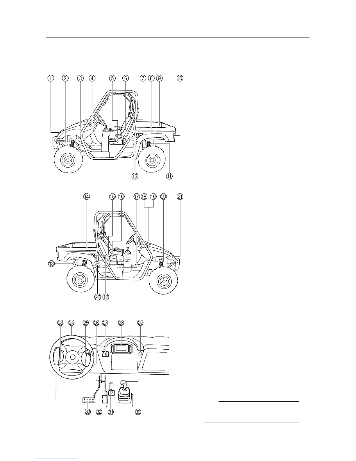
DESCRIPTION AND MACHINE IDENTIFICATION
1. Headlights
2. Front shock absorber assembly
adjusting ring
3. Brake fluid reservoir
4. Air filter element
(engine and air intake duct)
5. V-belt case
6. Driver seat
7. Driver seat belt
8. Spark plug
9. Cargo bed
10. Tail/brake lights
11. Rear shock absorber assembly
adjusting ring
12. Cargo bed release levers
13. Spark arrester
14. Passenger seat belt
15. Passenger seat
16. Oil filter cartridge
17. Engine oil dipstick
18. Battery
19. Fuses
20. Coolant reservoir
21. Radiator cap
22. Fuel tank cap
23. Light switch
24. Steering wheel
25. Starter (choke)
26. Main switch
27. On-Command four-wheel-drive
and differential lock switches
28. Multi-function meter unit
29. Auxiliary DC jack
30. Drive select lever
31. Parking brake lever
32. Accelerator pedal
33. Brake pedal
NOTE:
The vehicle you have purchased may
differ slightly from those in the figures
of this manual.
Page 14
GENERAL INFORMATION
1-2
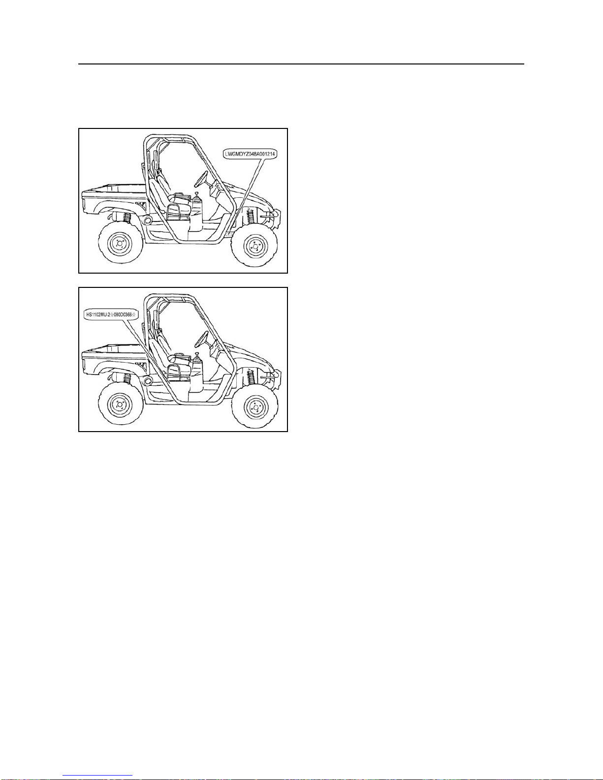
IDENTIFICATION CODE
Frame No.
Frame No. is carved in the lower right side of
Figure.
Engine No.
Engine NO. is carved on the right side of the
engine, Figure.
Page 15

GENERAL INFORMATION
1-3
CHAPTER ONE
GENERAL INFORMATION
The text provides complete information on maintenance,tune-up repair and overhaul,Hundreds
of photographs and illustrations created during the complete disassembly of UTV guide the reader
through every job,All procedures are in step-by-step format and designed for the reader who may be
working on the UTV for the first time
MANUAL ORGANIZATION
A shop manual is a tool and, as in all Clymer manuals, the chapters are thump tabbed for easy
reference, main heads are listed in the table of contents and the index, Frequently used specifications
and capacities from the tables at the end of each individual chapter are listed in the UTV, Quick
reference data section at the front of the manual specifications and capacities are provided in U.S
standard and metric units of measure
During some of the procedures, there will be reference to heading in other chapters or sections of
manual, when a specific heading is called out in a step it will be italicized as it indicated as being “in
this section”, it is located within the same main heading, For example, the sub-heading handling
Gasoline safely is located within the main heading SAFETY
This chapter provides general information on shop safety, tools and their usage, service
fundamentals and shop supplies.
WARNINGS, CAUTIONS AND NOTES
The terms WARNING, CAUTION and NOTE have specific meaning in this manual.
A WARNING emphasizes areas where injury or even death could result from negligence.
Mechanical damage may also occur. WARNINGS are to be taken seriously
A CAUTION emphasizes areas where equipment damage could result. Disregarding a CAUTION
could cause permanent mechanical damage. though injury is unlikely.
A NOTE provides additional information to make a step or procedure easier or clearer.
Disregarding a NOTE could cause inconvenience. but would not cause equipment damage or injury.
SAFETY
Professional mechanics can work for years and never sustain a serous injury or mishap. Follow
these guidelines and practice common sense to safely service the utility terrain venires
Page 16

GENERAL INFORMATION
1-4
1. Do not operate the utility terrain venires in an enclosed area venires The exhaust gasses contain
carbon monoxide. an odorless, colorless and tasteless poisonous gas. Carbon monoxide levels
build quickly in small enclosed areas and can cause unconsciousness and death in a short time.
Make sure to properly ventilate the work area or operate the UTV side
2. Never use gasoline or any extremely flammable liquid to clean parts. Refer to cleaning parts and
handling Gasoline Safely in this section
3. Never smoke or use a torch in the vicinity of flammable liquids, such as gasoline or cleaning
solvent.
4. If welding or brazing on the UTV the fuel tank to a safe distance at least 50ft.(15m) away.
5. Use the correct type and size of tools to avoid damaging fasteners.
6. Keep tools clean and in good condition. Repl ace or repair worn or damaged equipment.
7. When loosening a tight fastener, be guided by what would happen if the tool slips.
8. When replacing fasteners, make sure the new fasteners are the same size and strength as the
original ones.
9. Keep the work area clean and organized.
10. Wear eye protection anytime the safety of the eyes is in question. This includes procedures that
involve drilling, grinding, hammering, compressed air and chemicals.
11. Wear the correct clothing for the job. Tie up or cover long hair so it does not get caught in moving
equipment.
12. Do not carry sharp tools in clothing pockets.
13. Always have an approved fire extinguisher available. Make sure it is rated for gasoline (Class B)
and electrical (Class C) fires.
14. Do not use compressed air to clean clothes, the UTV or the work area. Debris may be blown into
the eyes or skin. Never direct compressed air at anyone. Do not allow children to use or play with
any compressed air equipment.
15. When using compressed air to dry rotating parts, hold the part so it does not rotate. Do not allow
the force of the air to spin the part. The air jet is capable of rotating parts at extreme speed. The
part may disintegrate of become damaged, causing serious injury.
16. Do not inhale the dust created by brake pad and clutch wear. These particles may contain
asbestos. In addition, some types of insulating materials and gaskets may contain asbestos.
Inhaling asbestos particles is hazardous to one’s health.
17. Never work on the UTV while someone is working under it.
Handling Gasoline Safely
Gasoline is a volatile flammable liquid and is one of the most dangerous items in the shop.
Because gasoline is used so often, many people forget it is hazardous. Only use gasoline as fuel
for gasoline internal combustion engines. Keep in mind when working on the machine, gasoline is
always present in the fuel tank, fuel line and carburetor. To avoid a disastrous accident when
working around the fuel system, carefully observe the following precautions:
1. Never use gasoline to clean parts. Refer to Cleaning Parts in this section.
2. When working of the fuel system, work outside or in a well-ventilated area.
3. Do not add fuel to the fuel tank or service the fuel system while the UTV is near open flames,
Page 17

GENERAL INFORMATION
1-5
sparks or where someone is smoking .Gasoline vapor is heavier than air, it collects in low areas
and is more easily ignited than liquid gasoline.
4. Allow the engine to cool completely before working on any fuel system component.
5. Do not store gasoline in glass containers. If the glass breaks, a serious explosion of fire may
occur.
6. Immediately wipe up spilled gasoline with rags. Store the rags in a metal container with a lid until
they can be properly disposed of, or place them outside in a safe place for the fuel to evaporate.
7. Do not pour water onto a gasoline fire. Water spreads the fire and makes it more difficult to put out.
Use a class B, BC or ABC fire extinguisher to extinguish the fire.
8. Always turn off the engine before refueling. Do not spill fuel onto the engine or exhaust system.
Do not overfill the fuel tank. Leave an air space at the top of the tank to allow room for the fuel to
expand due to temperature fluctuations.
Cleaning Parts
Cleaning parts is one of the more tedious and difficult service jobs performed in the home garage.
Many types of chemical cleaners and solvents are available for shop use. Most are poisonous and
extremely flammable. To prevent chemical exposure, vapor buildup, fire and serious injury, observe
each product warning label and note the following:
1. Read and observe the entire product label before using any chemical. Always know what type of
chemical is being used and whether it is poisonous and/or flammable.
2. Do not use more than one type of cleaning solvent at a time. If mixing chemicals is required,
measure the proper amounts according to the manufacturer.
3. Work in a well-ventilated area.
4. Wear chemical-resistant gloves.
5. Wear safety glasses.
6. Wear a vapor respirator if the instructions call for it.
7. Wash hands and arms thoroughly after cleaning parts.
8. Keep chemical products away from children and pets.
9. Thoroughly clean all oil, grease and cleaner residue from any part that must be heated.
10. Use a nylon brush when cleaning parts. Metal brushes may cause a spark.
11. When using a parts washer, only use the solvent recommended by the manufacturer. Make sure
the parts washer is equipped with a metal lid that will lower in case of fire.
Warning Labels
Most manufacturers attach information and warning labels to the UTV. These labels contain
instructions that are important to personal safety when operating, servicing, transporting and storing
the UTV. Refer to the owner’s manual for the description and location of labels. Order replacement
labels from the manufacturer if they are missing or damaged.
Page 18

GENERAL INFORMATION
1-6
SERIAL NUMBERS
Serial and identification numbers are stamped on various locations on the frame, engine and
carburetor body . Record these numbers in the Quick Re ference Dat a section in the front of the manual.
Have these numbers available when ordering parts.
FASTENERS
Proper fastener selection and installation is important to ensure the motorcycle operates as
designed and can be serviced efficiently. The choice of original equipment fasteners is not arrived at
by chance. Make sure replacement fasteners meet all the same requirements as the originals
Many screws. Bolts and studs are combined with nuts to secure particular components. to indicate
the size of a nut. Manufactures specify the internal diameter and the thread pitch
The measurement across two flats on a nut or bolt indicates the wrench size
WARNING
Do not install fasteners with a strength classification
lower than what was originally installed by the
manufacturer doing so may cause equipment failure
and or damage
Torque Specifications
The material used in the manufacturing of the UTV may be subjected to uneven stresses if the
fasteners of the various subassemblies are not installed and tightened correctly. Fasteners that are
improperly installed or work loose can cause extensive damage. it is essential to use an accurate
torque wrench as described in this chapter
Self-Locking Fasteners
Several types of bolts. Screws and nuts incorporate a system that creates interference between
the two fasteners. Interference is achieved in various ways. The most common types are the nylon
insert nut and a dry adhesive coating on the threads of a blot.
Self-locking fasteners offer greater holding strength than standard fasteners, which improves their
resistance to vibration. All self-locking fasteners cannot be reused. The materials used to from the lock
become distorted after the initial installation and removal. Discard and replace self-locking fasteners
after removing them. Do not replace self-locking fasteners with standard fasteners.
Page 19
GENERAL INFORMATION
1-7
Washers
The two basic types of washers are flat washers and lock washers. Flat washers are simple discs
with a hole to fit a screw or bolt. Lock washers are used to prevent a fastener from working loose.
Washers can be used as spacers and seals. Or can help distribute fastener load and prevent the
fastener from damaging the component
As with fasteners. When replacing washers make sure the replacement washers are of the same
design and quality
Cotter Pins
A cotter pin is a split metal pin inserted into a hole or slot to prevent a fastener from loosening. In
certain applications, such as the rear axle on an UTV or motorcycle, the fastener must be secured in
this way. For these applications. A cotter pin and castellated (slotted) nut is used.
To use a cotter pin, first make sure the diameter is correct for the hole in the fastener. Aster
correctly tightening the fastener and aligning the holes, insert the cotter pin through the hole and bend
the ends over the fastener, Unless instructed to do so, never loosen a tightened fastener to align the
holes. If the holes do not align. Tighten the fastener enough to achieve alignment
Cotter pins are available in various diameters and lengths. Measure the length from the bottom of
the head to the tip of the shortest pin
Snap Rings and E-clips
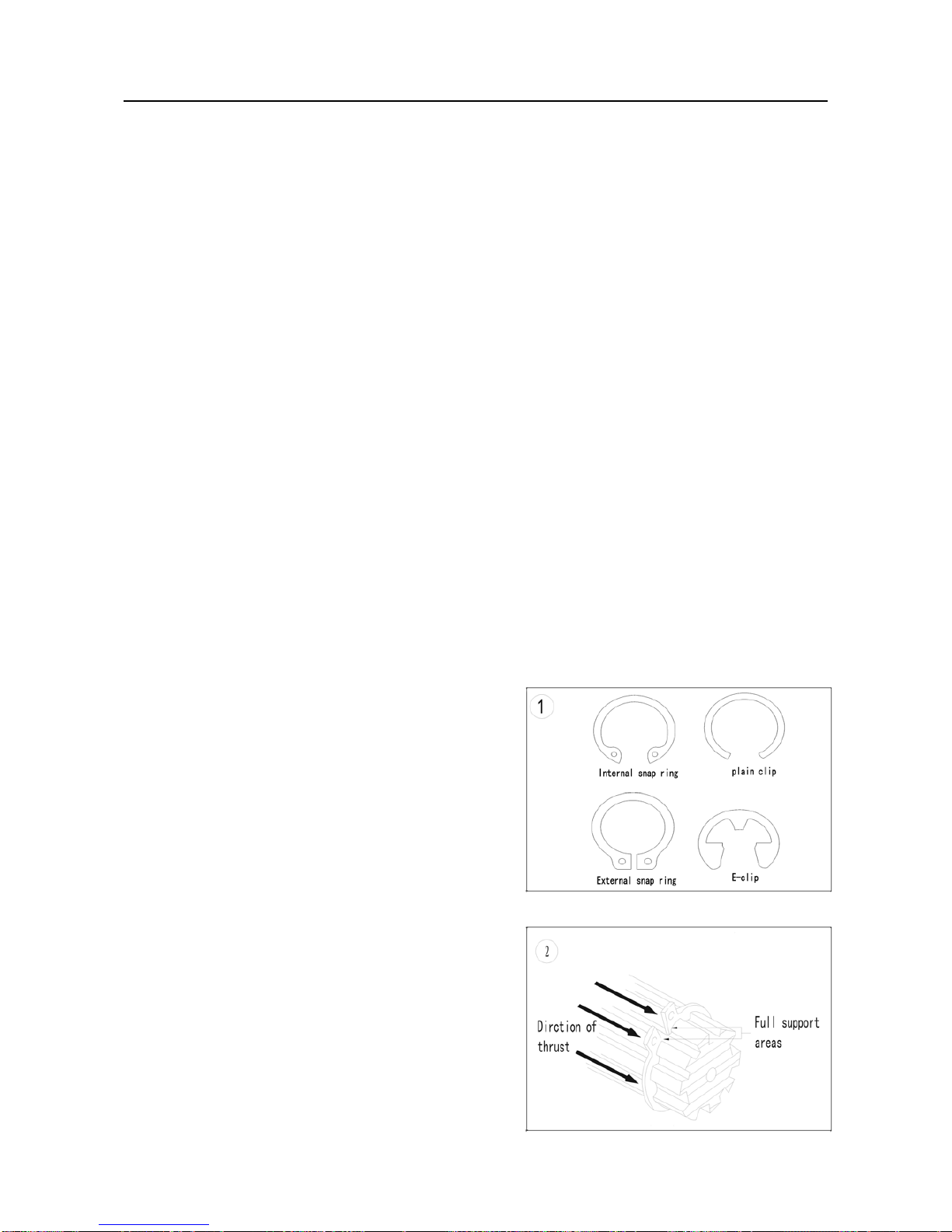
Snap rings (Figure 1) are circular-shaped metal
retaining clips. They secure parts in place on parts such
as shafts. External type snap rings are used to retain
items on shafts. Internal type snap rings secure parts
within housing bores. In some applications. in addition to
securing the component(s). snap rings of varying
thicknesses also determine endplay. These are usually
called selective snap rings.
The two basic types of snap rings are machined and
stamped snap rings. Machined snap rings (Figure 2) can
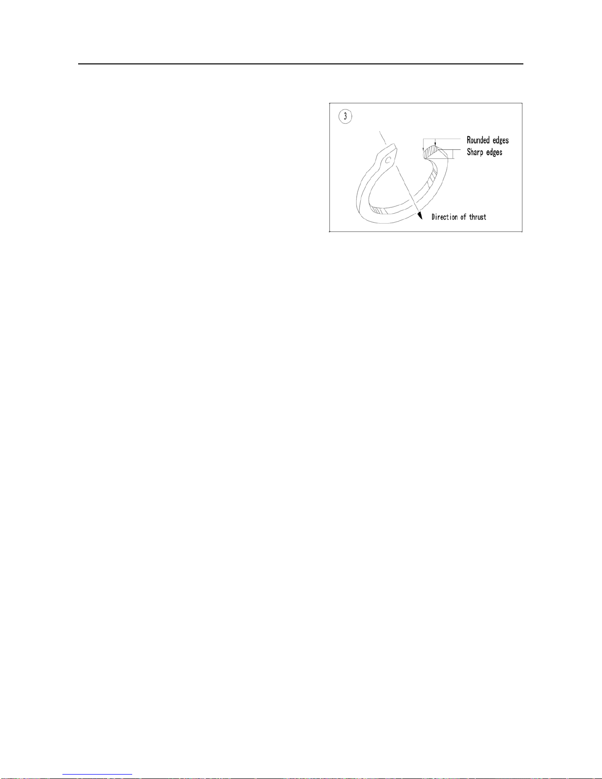
be installed in either direction. Because both faces have
sharp edges. Stamped snap rings (Figure 3) are
manufactured with a sharp and a round edge. When
installing a stamped snap ring in a thrust application,
install the sharp edge facing away from the part
producing the thrust.
E-clips are used when it is not practical to use a
snap ring. Remove E-clips with a flat blade screwdriver
by prying between the shaft and E-clip. To install an
E-clip. Center it over the shaft groove and push or tap it
Page 20
GENERAL INFORMATION
1-8
into place
Observe the following when installing snap rings:
1. Remove and install snap rings with snap rings
pliers. Refer to Basic Tools in this chapter
2. In some applications. it may be necessary to
replace snap rings after removing them
3. Compress or expand snap rings only enough to
install them. If overly expanded. Lose their
retaining ability
4. After installing a snap ring. Make sure it seats
completely
5. Wear eye protection when removing and
installing snap rings
SHOP SIPPLIES
Lubricants and Fluids
Periodic lubrication help ensure a long service life for any type of equipment. Using the correct
type of lubricant is as important as performing the lubrication service. Although in an emergency the
wrong type is better than not using one, The following section describes the types of lubricants most
often required. Make sure to follow the manufacturer’s recommendations for lubricant types
Engine oils
Engine oil for four-stroke motorcycle UTV engine use is classified by three standards: the
American Petroleum Institute (API) service classification. The Society of Automotive Engineers (SAF)
viscosity rating Standard classification
The API and SAE information is on all oil container labels. Two letters indicate the API service
classification. The number or sequence of numbers and letter (10W-40 for example) is the oil’s
viscosity rating. The API service classification and the SAE viscosity index are not indications of oil
quality.
The APL ser vice classification standards, The fir st letter in the classification S indicates that the oil
is for gasoline engines. The second letter indicates the standard the oil satisfies .
The classifications are: MA (high friction applications) and MB( low frication applications).
NOTE
Refer to Engine Oil and Filter in
Chapter Three for further information
on API, SAE classifications.
Always use an oil with a classification recommended by the manufacturer, Using an oil with a
different classification can cause engine damage.
Page 21

GENERAL INFORMATION
1-9
Viscosity is an indication of the oil’s thickness. Thin oils have a lower number while thick oil have a
higher number. Engine oils fall into the 5-to50-weight range for single-grade oils.
Most manufactures recommend multi-grade oil. These oils perform efficiently across a wide
range of operating conditions. Multi-grade oils are identified by a W after the first number, which
indicates the low-temperature viscosity.
Engine oils are most commonly mineral (petroleum) based, but synthetic and semi-synthetic types
are used more frequently. When selecting engine oil, follow the manufacturer’s recommendation for
type, classification and viscosity.
Greases
Grease is lubricating oil with thickening agents added to it. The National Lubricating Grease
Institute (NLGI) grades grease. Grades range from No.000 to No.6, with No.6 being the thickest.
Typical multipurpose grease is NLGI No.2. For specific applications, manufacturers may recommend
water-resistant type grease or one with an additive such as molybdenum disulfide (MoS2).
Brake fluid
Brake fluid is the hydraulic fluid used to transmit hydraulic pressure (force) to the wheel brakes.
Brake fluid is classified by the Department of Transportation (DOT). Current designations for brake
fluid are DOT 3, DOT 4 and DOT 5, this classification appears on the fluid container.
Each type of brake fluid has its own definite characteristics. Do not intermix different types of brake
fluid as this may cause brake system failure. DOT 5 brake fluid is silicone based. DOT 5 is not
compatible with other brake fluids may cause brake system failure. When adding brake fluid, only use
the fluid recommended by the manufacturer.
Brake fluid will damage any plastic, painted or plated surface it contacts. Use extreme care when
working with brake fluid and remove any spills immediately with soap and water.
Hydraulic brake systems require clean and moisture free brake fluid. Never reuse brake fluid.
Keep containers and reservoirs properly sealed.
WARNING
Never put a mineral-based (Petroleum) oil into the
brake system. Mineral oil causes rubber parts in
the system to causing complete brake failure.
Coolant
Coolant is a mixture of water and antifreeze used to dissipate engine heat. Ethylene glycol is the
most common from of antifreeze. Check the motorcycle Manufacturer’s recommendations when
selecting antifreeze. Most require one specifically designed for aluminum engines. There types of
antifreeze have additives that inhibit corrosion.
Only mix antifreeze with distilled water. Impurities in tap water may damage internal cooling
system passages.
Page 22

GENERAL INFORMATION
1-10
Cleaners, Degreasers and Solvents
Many chemicals are available to remove oil, grease and other residue from the motorcycle UTV.
Before using cleaning solvents, consider how they will be used and disposed of , particularly if they are
not water-soluble. Local ordinances may types of cleaning chemicals. Refer to Safer in this chapter.
Use brake parts cleaner to brake system components. Brake parts cleaner leaves no residue. Use
electrical contact cleaner is a powerful solvent used to remove fuel deposits and varnish from fuel
system components. Use this cleaner carefully, as it may damage finishes.
Most solvents are designed to be used with a parts washing cabinet for individual component
cleaning. For safety, use only nonflammable or high flash point solvents.
Gasket Sealant
Sealant is used in combination with a gasket or seal. In other applications, such as between
crankcase halves, only a sealant is used. Follow the manufacturer’s recommendation when using a
sealant. Use extreme care when choosing a sealant different sealant based on its resistance to heat,
various fluids and its sealing capabilities.
A common sealant is room temperature vulcanization sealant, or RTV. This sealant cures at room
temperature over a specific time period. This allows the repositioning of components without damaging
gaskets.
Moisture in the air causes the RTV sealant to cure. Always install the cap as soon as possible
after applying RTV sealant. RTV sealant has a limited shelf life and will not cure properly if the shelf life
has expired. Keep partial tubes sealed and discard them if they have surpassed the expiration date.
Applying RTV sealant
Clean all old gasket residues from the mating surfaces. Remove all gasket material from the
mating surfaces. Remove all gasket material from blind threaded holes to avoid inaccurate bolt torque.
Spray the mating surfaces with aerosol parts cleaner and then wipe with a lint-free cloth. The area
must be clean for the sealant to adhere.
Apply RTV sealant in a continuous bead 2-3 mm (0.08-0.12 in.) thick. Circle all the fastener holes
unless otherwise specified. Do not allow any sealant to enter these holes. Assemble and tighten the
time frame recommended by the sealant manufacturer.
Gasket Remover
Aerosol gaskets remover can help remove stubborn gasket. This product can speed up the
removal process and prevent damage to the mating surface that may be caused by using a scraping
tool. Most of these types of products are very caustic. Follow the gasket remover manufacturer’s
instructions for use.
Thread locking Compound
A thread locking compound is a fluid applied to the threads of fasteners. After tightening the
fastener, the fluid dries and becomes a solid filler between the threads. This makes it difficult for the
Page 23

GENERAL INFORMATION
1-11
fastener to work loose from vibration or hear expansion and contraction. Some thread locking
compound sparingly. Excess fluid can run into adjoining parts.
CAUTION
Thread locking compounds are anaerobic and will stress,
crack and attack most plastics. Use caution when using
These products in areas where there are plastic
components.
Thread locking compounds are available in a wide range of compounds for various strength,
temperature and repair applications. Follow the manufacturer’s recommendations regarding
compound selection.
BASIC TOOLS
Most of the procedures in this manual can be carried out with basic hand tools and test equipment
familiar to the home mechanic. Always use the correct tools for the job. Keep tools organized and
clean. Store them in a tool chest with related tools organized together.
Quality tools are essential. The best are constructed of high-strength alloy steel. These tools are
light, easy to use and resistant to wear. Their working surface is devoid of sharp edges and carefully
polished. They have an easy-to-clean finish and are comfortable to use. Quality tools are a good
investment.
Some of the procedures in this manual specify special tools. In many cases the tools is illustrated
in use. Those with a large tool kit may be able to replacement. However, in some cases, the
specialized equipment or expertise may make it impractical for the home mechanic to attempt the
procedure. When necessary, such operations are recommended to have a dealership or specialist
perform the task. It may be less expensive to have a professional perform these jobs, especially when
considering the cost of equipment.
When purchasing tools to perform the procedures covered in this manual, consider the tool’s
potential frequency of use. If a tool kit is just now being started. Consider purchasing a basic tool set
from a quality tool combinations and offer substantial savings when complicated, specialized tools can
be added.
Screwdrivers
Screwdrivers of various lengths and types are mandatory for the simplest tool kit. The two basic
types are the slotted tip (flat blade) and the Phillips tip. These are available in sets that often include an
assortment of tip size and shaft lengths.
As with all tools, use a screwdriver designed for the job. Make sure the size of the fastener. Use
them only for driving screws. Never use a screwdriver for prying or chiseling metal. Repair or replace
worn or damaged screwdrivers. A worn tip may damage the fastener, making it difficult to remove.
Phillips-head screws are often damaged by incorrectly fitting screwdrivers. Quality Phillips
screwdrivers are manufactured with their crosshead tip machined to Phillips Screw Company
Page 24
GENERAL INFORMATION
1-12
specifications. Poor quality or damaged Phillips
screwdrivers can back out (cam out) and round over
the screw head. In addition. Weak or soft screw
materials can make removal difficult.
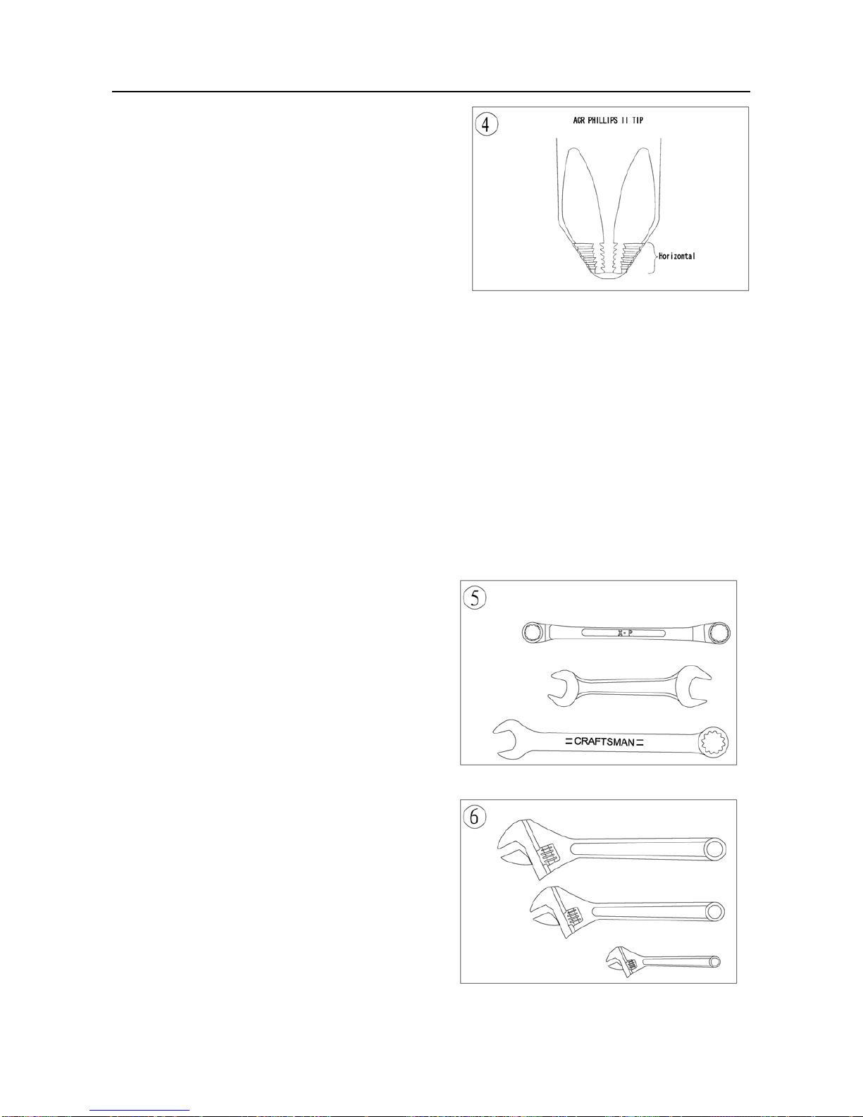
The best type of screwdriver to use on Phillips
screw is the ACR Phillips II screwdriver, patented by
the horizontal anti-cam out ribs found on the driving
faces or flutes of the screwdriver’s tip (figure 4). ACR
Phillips II screwdrivers were designed as part of a
manufacturing drive system to be used with ACR
Phillips II screws, but they work of tool companies offer ACR Phillips II screwdrivers in different Tip size
and interchangeable bits to fit screwdriver bit holders.
NOTE
Another way to prevent cam out and to increase the
grip of a Phillips screwdriver is to apply valve grinding
compound or permute screw
&
socket Gripper onto
the screwdriver tip. After loosening/tightening the screw,
clean the screw recess to prevent engine oil
contamination.
Wrenches
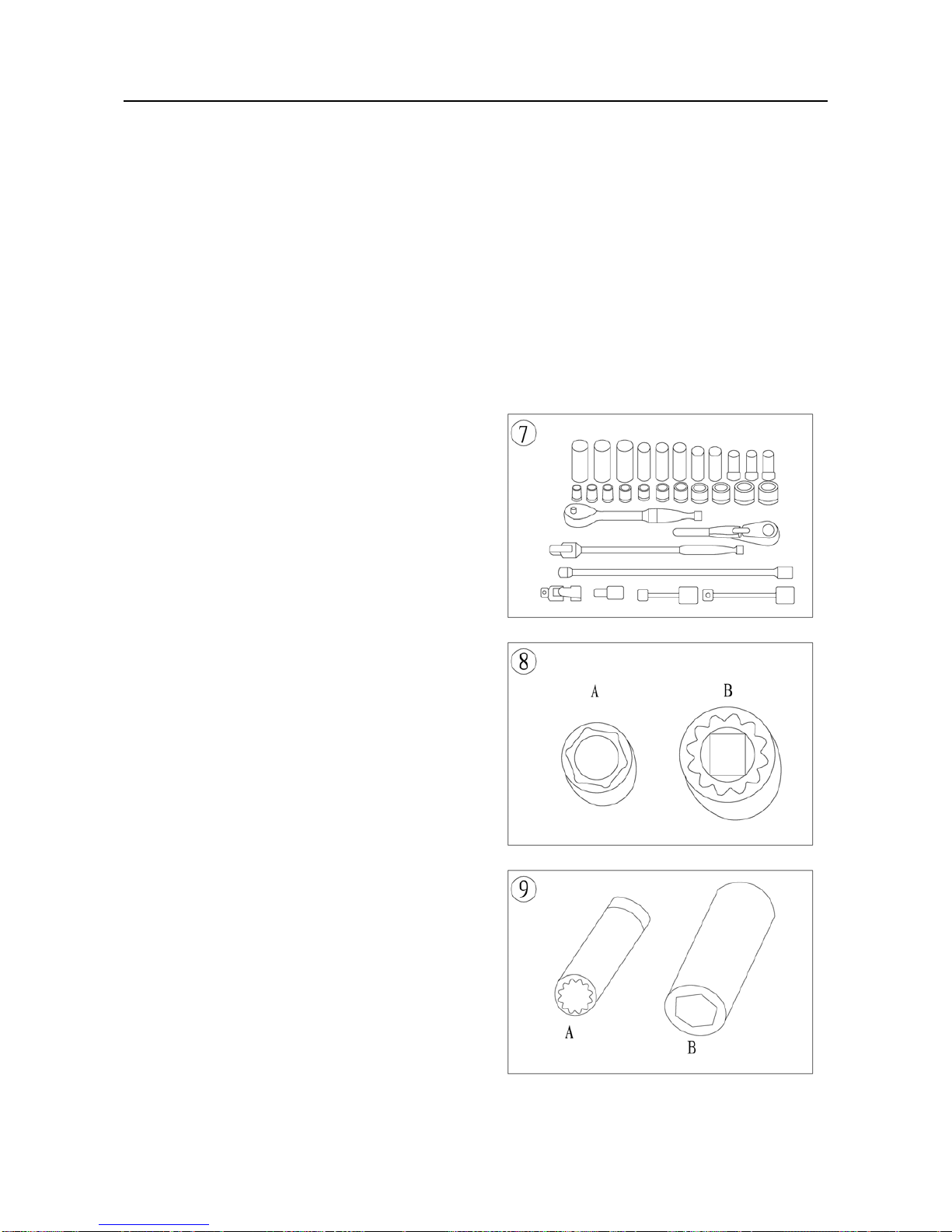
Open-end, box-end and combination wrenches
(figure 5) are available in a variety of types and sizes.
The number stamped on the wrench refers to the
distance of the fastener head.
The box-end wrench is an excellent tool because
it grips the fastener on all sides. This reduces the
chance of the tool slipping. The box-end wrench is
designed with either a 6 or 12-point opening. For
stubborn or damaged fasteners, the 6-point provides
superior holding because it contacts the fastener
across a wider area at all six edges. For general use,
the 12-point works well. It allows the wrench to be
removed and reinstalled without moving the handle
over such a wide are.
An open-end wrench is fast and works best in
areas with limited overhead access. It contacts the
fastener at only two points and is subject to slipping if
under heavy force, or if the tool or fastener is worn. A
box-end wrench is preferred in most instances,
especially when braking loose and applying the final
tightness to a fastener.
The combination wrench has a box-end on one end and an open-end on one end and an
Page 25
GENERAL INFORMATION
1-13
open-end on the other. This combination makes it a convenient tool.
Adjustable wrenches
An adjustable wrench or Crescent wrench (Figure 6) can fit nearly any nut or bolt head that has
clear access around its entire perimeter. An adjustable wrench is best used as a backup wrench to
keep a large nut or bolt from turning while the other end is being loosened or tightened with a box-end
or socket wrench.
Adjustable wrenches contact the fastener at only two points, which makes them more subject to
slipping off the fastener. Because one jaw is adjustable and may become loose, this shortcoming is
aggravated. Make certain the solid jaw is the one transmitting the force.
Socket Wrenches, Ratchets and Handles
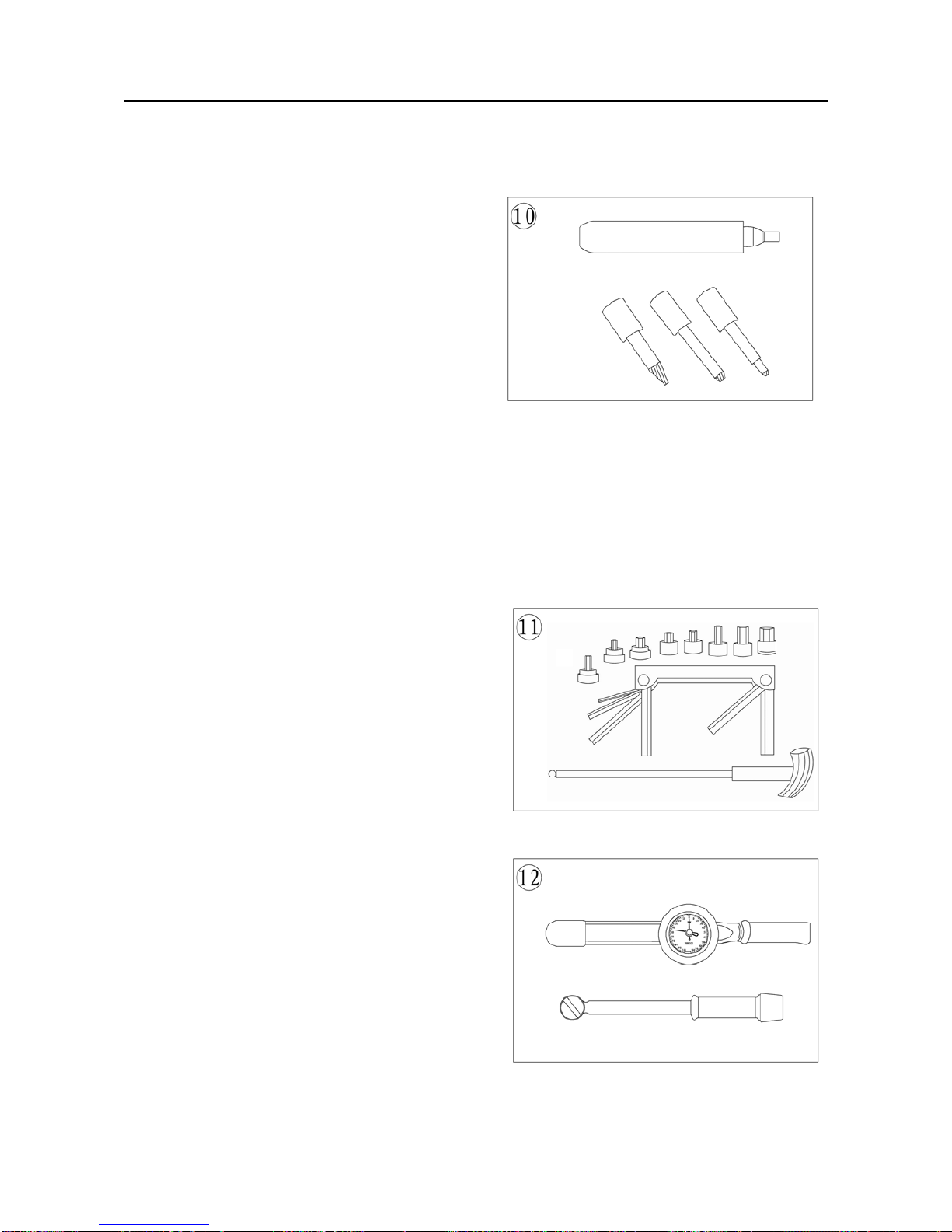
Sockets that attach to a ratchet handle (Figure 7)
are available with 6-point or 12-point openings (Figure
8) and different drive sizes. The drive size indicates
the size of the square hole that accepts the ratchet
handle. The number stamped on the socket is the size
of the work area and must the fastener head
As with wrenches. a 6-point provides
superior-holding ability. While a 12-point socket needs
to be moved only half as for to reposition it on the
fastener
Sockets are designated for either hand or impact
use. Impact sockets are made of thicker material for
more durability. Compare the size and wall thickness
of a 19-mmhand socket (A, Figure 9) and the 19-mm
impact socket (B). Use impact sockets when using an
impact driver or air tools. Use hand sockets with
hand-driven attachments
WARNING
Do not use hand sockets with air or impact
tools because they may shatter and cause
injury. Always wear eye protection when using
impact or air tools
Various handles are available for sockets. Use the
speed handle for fast operation. Flexible ratchet heads
in varying length allow the socket to be turned with
varying force and at odd angles. Extension bars allow
the socket setup to reach difficult areas. The ratchet is
the most versatile. It allows the user to install or remove the nut without removing the socket
Sockets combined with any number of drivers make them undoubtedly the fastest. Safest and
Page 26
GENERAL INFORMATION
1-14
most convenient tool for fastener removal and installation
Impact Drivers
An impact driver provides extra force for removing
fasteners by converting the impact of a hammer into a
turning motion. This makes it possible to remove
stubborn fasteners without damaging them. Impact
drivers and interchangeable bits (Figure 10) are
available from most tool suppliers. When using a
socket with an impact driver. Make sure the socket is
designed for impact use. Refer to Socket Wrenches.
Ratchets and handles in this section.
WARNING
Do not use hand sockets with air or impact
tools because they may shatter and cause
injury. Always wear eye protection when
using impact or air tools
Allen Wrench es
Use Allen or setscrew wrenches (Figure 11) on
fasteners with hexagonal recesses in the fastener
head. These wrenches are available in L-shaped bar.
Socket and T-handle types. A metric set is required
when working on most motorcycles. Allen bolts are
sometimes called socket bolts.
Torque W r enches
Use a torque wrench with a socket, torque
adapter or similar extension to tighten a fastener to a
measured torque. Torque wrenches come in several
drive sizes (1/4, 3/8, 1/2 and 3/4) and have various
methods of reading the torque value. The drive size
indicates the size of the square drive that accepts the
socket, adapter or extension. Common methods of
reading the torque value are the deflecting beam, the
dial indicator and the audible click (Figure 12).
When choosing a torque wrench, consider the
torque range, drive size and accuracy. The torque
specifications in this manual provide an indication of
the range required.
A torque wrench is a precision tool that must be properly cared for to remain accurate. Store
Page 27
GENERAL INFORMATION
1-15
torque wrenches in cases or separate padded drawers within a toolbox. Follow the manufacturer’s
instructions for their care and calibration.
T or que Adapters
Torque adapters or extensions extend or reduce
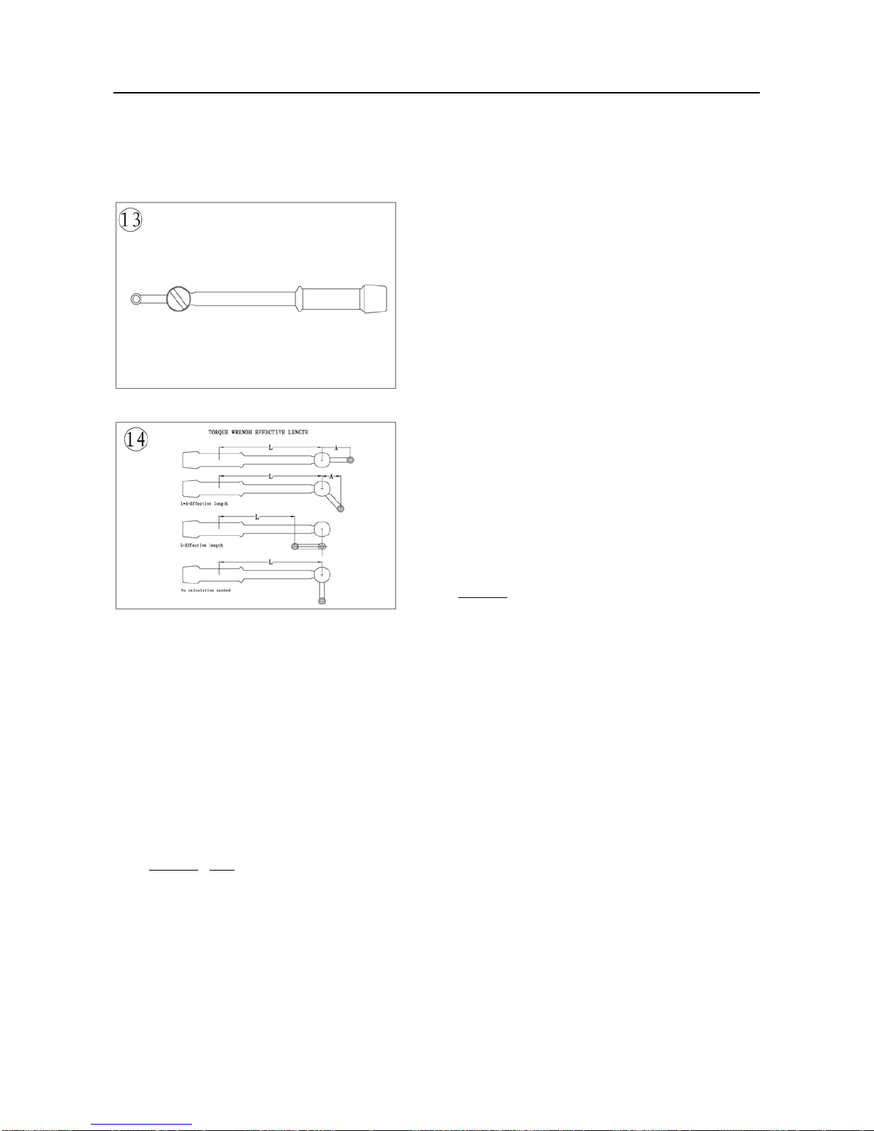
the reach of a torque wrench. The torque adapter
shown in (Figure 13) is used to tighten a fastener that
cannot be reached because of the size of the torque
wrench head, drive, and socket. If a torque adapter
changes the effective lever length (Figure 14), the
torque reading on the wrench will not equal the actual
torque applied to the fastener. It is necessary to
recalibrate the torque setting on the wrench to
compensate for the change of lever length. When
using a torque adapter at a right angle to the drive
head, calibration is not required, because the effective
length has not changed.
To recalculate a torque reading when using a
torque adapter, use the following formula and refer to
Figure 14:
TW = TA×L
L+A
TW is the torque setting or dial reading on the wrench.
TA is the torque specification and the actual amount of torque that is applied to the fastener.
A is the amount that the adapter increases (or in some cases reduces) the effective lever length as
measured along the centerline of the torque wrench.
L is the lever length of the wrench as measured from the center of the drive to the center of the grip.
The effective length is the sum of L and A.
Example:
TA=20 ft.-lb.
A=3in.
L=14in.
TW=20×14=280=16.5 ft. - lb.
14+3 = 17
In this example, the torque wrench would be set to the recalculated torque value (TW = 16.5 ft.
–lb.). When using a beam-type wrench, tighten the fastener until the pointer aligns with 16.5 ft. –lb. In
this example, although the torque wrench is pre set to 16.5 ft. –lb., the actual torque is 20 ft. –lb.
Page 28
GENERAL INFORMATION
1-16
Pliers
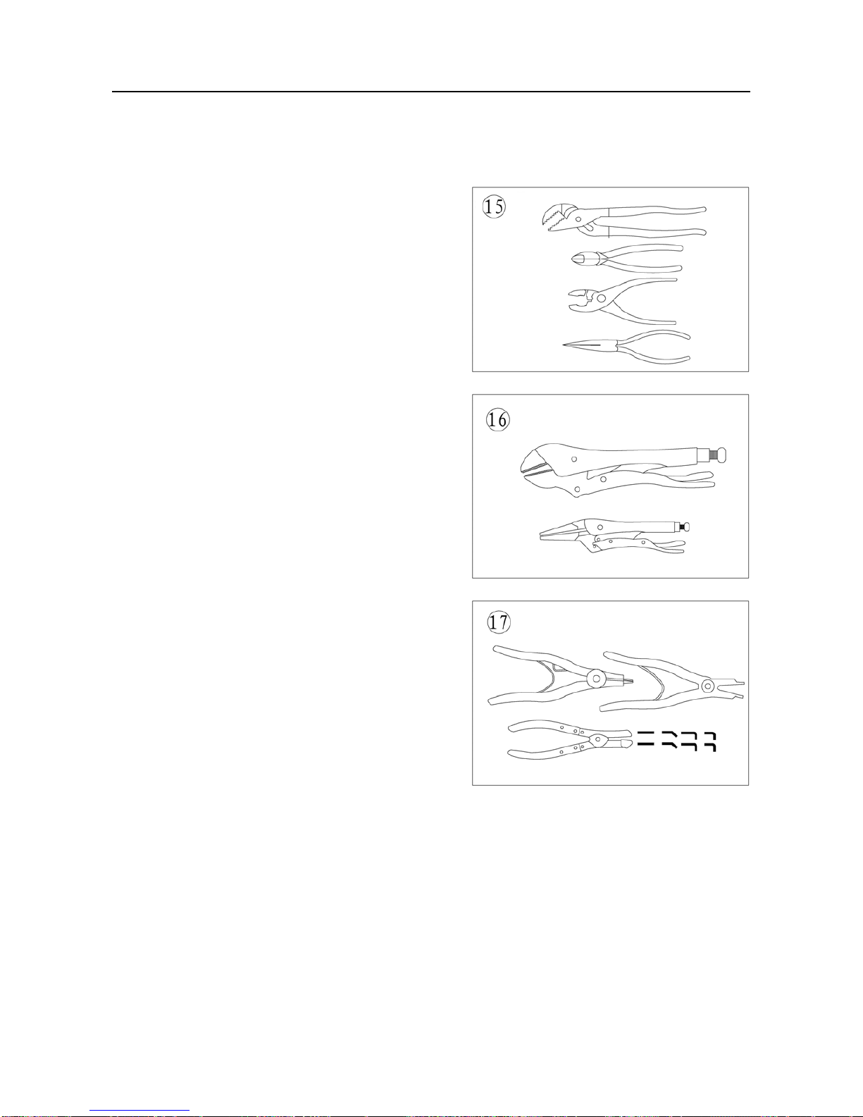
Pliers come in a wide range of types and sizes.
Pliers are useful for holding, cutting, bending, and
crimping. Do not use them to turn fasteners. Figure 15
and Figure 16 show several types of useful pliers.
Each design has a specialized function. Slip-joint
pliers are general – purpose pliers used for gripping
and bending. Diagonal cutting pliers are needed to cut
wire and can be used to remove cotter pins. Use
needle nose pliers to hold or bend small objects.
Locking pliers (Figure 16), sometimes called ViseGrips, are used to hold objects very tightly. They have
many uses ranging from holding two parts together, to
gripping the end of a broken stud. Use caution when
using locking pliers, as the sharp jaws will damage the
objects they hold.
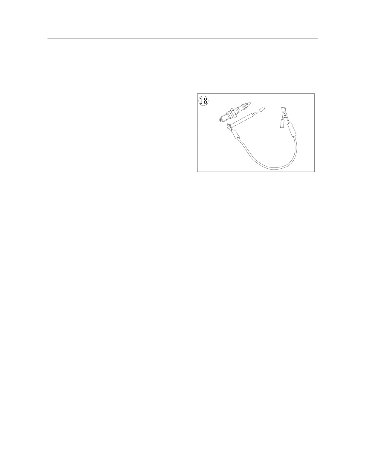
Snap Ring Pliers
Snap ring pliers are specialized pliers with tips that
fit into the ends of snap rings to remove and install
them.
Snap ring pliers (Figure 17) are available with a
fixed action (either internal or external ) or convertible
(one tool works on both internal and external snap
rings). They may have fixed tips or interchangeable
ones of various sizes and angles. For general use,
select a convertible type pliers with interchangeable
tips (Figure 17).
WARNING
Snap rings can slip and fly off when removing
and installing them. Also, the snap ring pliers
tips may break. Always wear eye protection
when using snap ring pliers.
Hammers
V arious types of hammers are available to fit a number of applications. Use a ball-peen hammer to
strike another tool, such as a punch or chisel. Use soft-faced hammers when a metal object must be
struck without damaging it. Never use a metal-faced hammer on engine and suspension components
because damage occurs in most cases.
Always wear eye protection when using hammers. Make sure the hammer face is in good
Page 29
GENERAL INFORMATION
1-17
condition and the handle is not cracked. Select the correct hammer for the job and make sure to strike
the object squarely. Do not use the handle or the side of the hammer to strike an object.
Ignition Grounding Tool
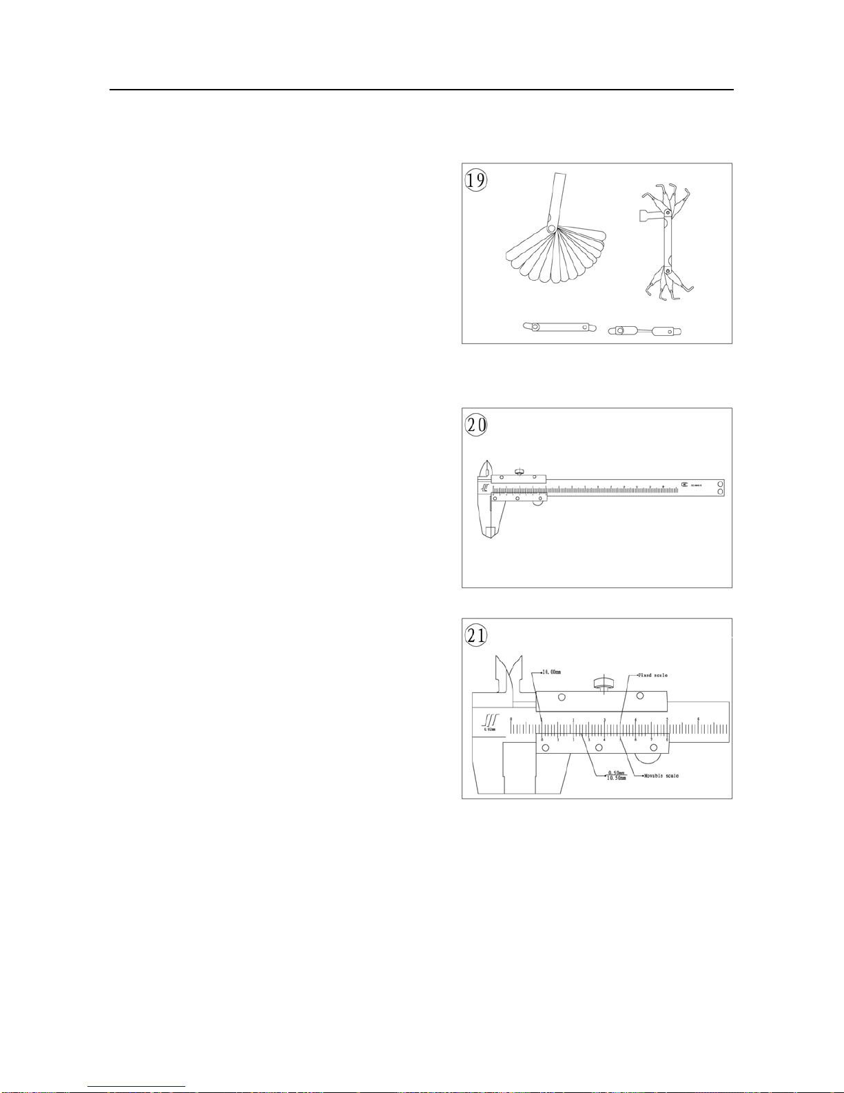
Some test procedures require turning the engine
over without starting it. To prevent damage to the
ignition system from excessive resistance or the
possibility of fuel vapor being ignited by an open spark,
remove the spark plug cap and ground it directly to a
good engine ground with the tool shown in (Figure
18).
Make the tool shown from a No.6 screw and nut,
two washers, length of tubing, alligator clip, electrical
eyelet and a length of wire.
PRECISION MEASURING TOOLS
The ability to accurately measure components is essential to perform many of the procedures
described in this manual. Equipment is manufactured to close tolerances, and obtaining consistently
accurate measurements is essential to determine which components require replacement or further
service.
Each type of measuring instrument is designed to measure a dimension with a certain degree of
accuracy and within a certain range. When selecting the measuring tool, make sure it is applicable to
the task.
As with all tools, measuring tools provide the best results if cared for properly. Improper use can
damage the tool and cause inaccurate results. If any measurement is questionable, verify the
measurement using another tool. A standard gauge is usually provided with micrometers to check
accuracy and calibrate the tool if necessary.
Precision measurements can vary according to the experience of the person performing the
procedure. Accurate results are only possible if the mechanic possesses a feel for using the tool.
Heavy-handed use of measuring tools produces less accurate results. Hold the tool gently by the
fingertips to easily feel the point at which the tool contacts the object. This feel for the equipment
produces more accurate measurements and reduces the risk of damaging the tool or component.
Refer to the following sections for specific measuring tools.
Page 30
GENERAL INFORMATION
1-18
Feeler Gauge
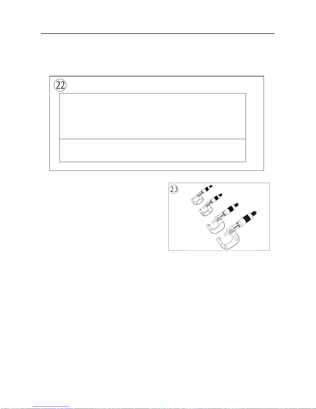
Use feeler or thickness gauges (Figure19) for
measuring the distance between two surfaces.
A feeler gauge set consists of an assortment of
steel strips of graduated thickness. Each blade is
marked with its thickness. Blades can be of various
lengths and angles for different procedures.
A common use for a feeler gauge is to measure
valve clearance. Use wire (round) type gauges to
measure spark plug gap.
Calipers
Calipers (Figure 20) are excellent tools for
obtaining inside, outside and depth measurements.
Although not as precise as a micrometer, they allow
reasonable precision, typically to within 0.05 mm
(0.001 in.). Most calipers have a range up to 150 mm
(6 in.).
Calipers are available in dial, venire or digital
versions. Dial calipers have a dial readout that
provides convenient reading. Venire calipers have
marked scales that must be compared to determine
the measurement. The digital caliper uses a
liquid-crystal display (LCD) to show the measurement.
Properly maintain the measuring surfaces of the
caliper. There must not be any dirt or burrs between
the tool and the object being measured. Never force
the caliper to close around an object. Close the caliper
around the highest point so it can be removed with a
slight drag. Some calipers require calibration. Always
refer to the manufacturer’s instructions when using a
new or unfamiliar caliper.
To read a vernire. Calipers refer to Figure 21. The fixed scale is marked in l-mm increments. Ten
individual lines on the fixed scale equal 1 cm. The movable scale is marked in 0.05 mm (hundredth)
increments. To obtain a reading, establish the first number by the location of the 0 line on the movable
scale in relation to the first line to the left on the fixed scale. In this example, the number is 10 mm. To
determine the next number, note which of the lines on the movable scale align with a mark on the fixed
scale. A number of lines will seem close, but only one will align exactly. In this case, 0.50 mm is the
reading to add to the first number. Adding 10 mm and 0.50 mm equals a measurement of 10.50 mm.
Page 31
GENERAL INFORMATION
1-19
Micrometers
A micrometer is an instrument designed for linear measurement using the decimal divisions of
the inch or meter (Figure 22). While there are many types and styles of micrometers, most of the
procedures in this manual call for an outside
micrometer. Use the outside micrometer to measure
the outside diameter of cylindrical forms and the
thickness of materials.
A micrometer’s size indicates the minimum and
maximum size of a part that it can measure. The usual
sizes (Figure 23) are 0-25mm (0-1 in.), 25-50 mm (1-2
in.), 50-75 mm (2-3 in.) and 75-100 mm (3-4 in.).
Micrometers that cover a wider range of
measurements are available. These use a large frame
with interchangeable anvils of various lengths. This type of micrometer offers a cost savings, but its
overall size may make it less convenient.
When reading a micrometer, numbers are taken from different scales and added together. The
following sections describe how to adjust, care for and read the measurements of various types of
outside micrometers.
For accurate results, properly maintain the measuring surfaces of the micrometer. There cannot
be any dirt or burrs between the tool and the measured object. Never force the micrometer to close
around an object. Close the micrometer around the highest point so it can be removed with a slight
drag.
Adjustment
Before using a micrometer, check its adjustment as follows:
1. Clean the anvil and spindle faces.
2A. To check a 0-1 in. or 0-25 mm micrometer:
a. Turn the thimble until the spindle contacts the anvil. If the micrometer has a ratchet stop, use it to
ensure that the proper amount of pressure is applied.
DECIMAL PLACE VALUES*
0.1 Indicates 1/10 (one tenth of an inch or
millimeter)
0.01 Indicates 1/100 (one one-hundredth of
an inch or millimeter)
0.001 Indicates 1/1000 (one one-thousandth
of an inch or millimeter)
*This chart represents the values of figures placed to the right of the decimal point. Use
it when reading decimals from one-tenth to one one-thousandth of an inch or millimeter.
It is not a conversion chart (for example: 0.001 in. is not equal to 0.001 mm).
Page 32
GENERAL INFORMATION
1-20
b. If the adjustment is correct, the 0 mark on the thimble will align exactly with the 0 mark on the
sleeve line. If the marks do not align, the micrometer is out of adjustment.
c. Follow the manufacturer’s instructions to adjust the micrometer.
2B. To check a micrometer larger than 1 in. or 25 mm use the standard gauge supplied by the
manufacturer. A standard gauge is a steel block, disc or rod that is machined to an exact size.
a. Place the standard gauge between the spindle and anvil, and measure its outside diameter or
length. If the micrometer has a ratchet stop, use it to ensure that the proper amount of pressure is
applied.
b. If the adjustment is correct, the 0 mark on the thimble will align exactly with the 0 mark on the
sleeve line. If the marks do not align, the micrometer is out of adjustment.
c. Follow the manufacturer’s instructions to adjust the micrometer.
Care
Micrometers are precision instruments. They must be used and maintained with great care. Note
the following:
1. Store micrometers in protective cases or separate padded drawers in a tool box.
2. When in storage, make sure the spindle and anvil faces do not contact each other or another object.
If they do, temperature changes and corrosion may damage the contact faces.
3. Do not clean a micrometer with compressed air. Dirt forced into the tool will cause wear.
4. Lubricate micrometers with WD-40 to prevent corrosion.
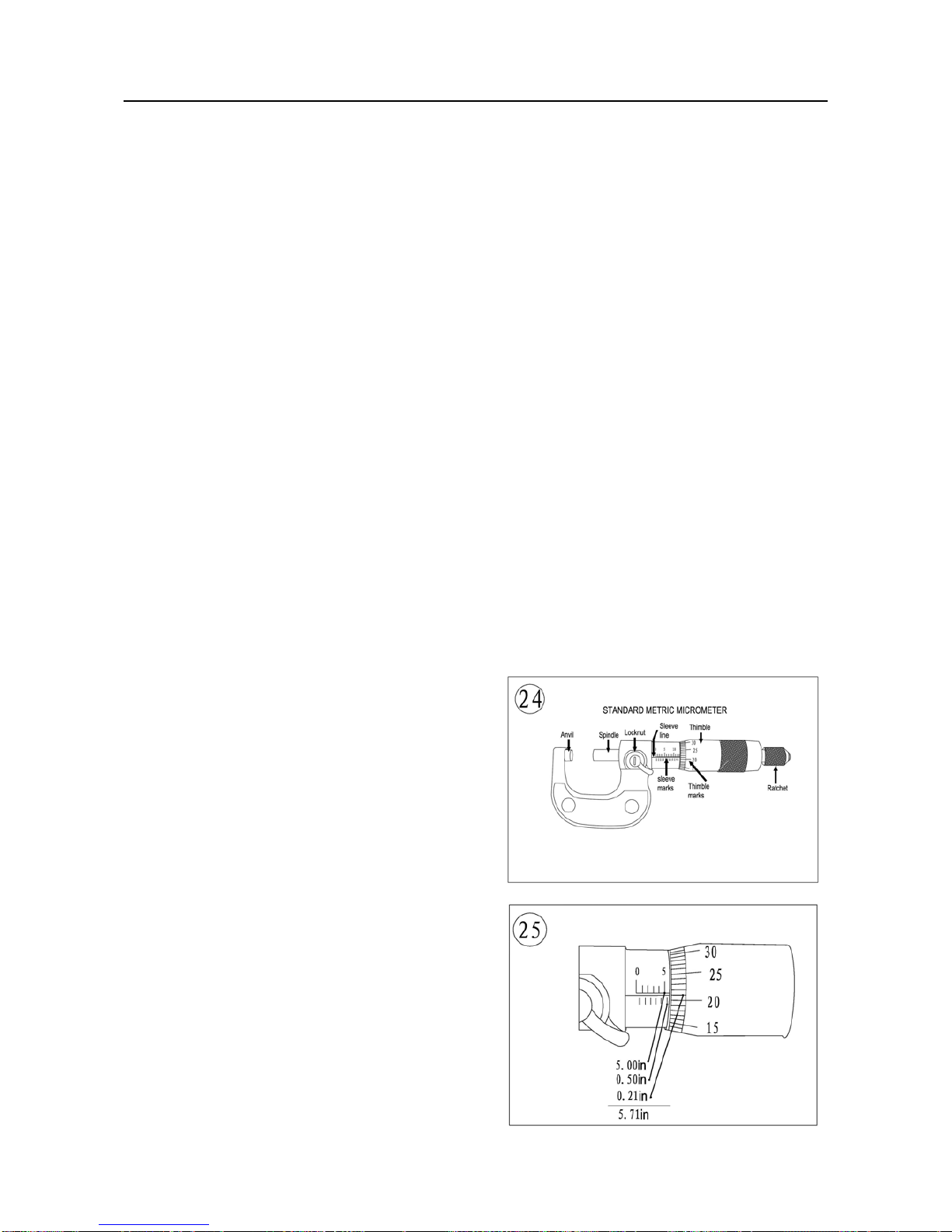
Metric micrometer
The standard metric micrometer (Figure 24) is
accurate to one one-hundredth of a millimeter (0.01
mm). The sleeve line is graduated in millimeter and
half millimeter increments. The marks on the upper
half of the sleeve line equal 1.00 mm. Each fifth mark
above the sleeve line is identified with a number. The
number sequence depends on the size of the
micrometer. A 0-25 mm micrometer, for example, will
have sleeve marks numbered 0 through 25 in 5 mm
increments. This numbering sequence continues with
larger micrometers. On all metric micrometers, each
mark on the lower half of the sleeve equals 0.50 mm.
The tapered end of the thimble has 50 lines
marked around it. Each mark equals 0.01 mm. One
completer turn of the thimble aligns its 0 mark with the
first line lower half of the sleeve line or 0.50mm.
When reading a metric micrometer, add the
number of millimeters and half-millimeters on the
sleeve line to the number of one one-hundredth
millimeters on the thimble. Perform the following steps
while referring to Figure 25.
Page 33
GENERAL INFORMATION
1-21
1. Read the upper half of the sleeve line and count the number of lines visible. Each upper line
equals 1mm.
2. See if the half –millimeter line is visible on the lower sleeve line. If so, add 0.50mm to the reading
in Step 1.
3. Read the thimble mark that aligns with the sleeve line. Each thimble mark equals 0.01mm.
NOTE
If a thimble mark does not align exactly with the
sleeve line. Estimate the amount between the
lines. For accurate readings in two-thousandths
of a millimeter (0.002mm), use a metric vernier
micrometer.
4. Add the readings from Steps 1-3.
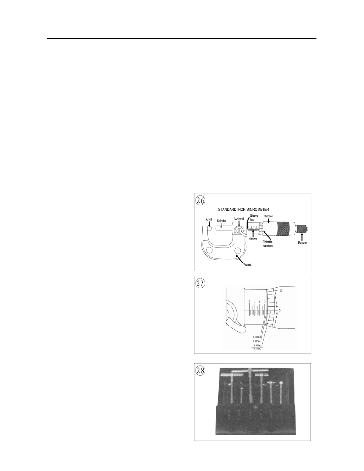
Standard inch micrometer
The standard inch micrometer (Figure 26) is
accurate to one-thousandth of an inch or 0.001. The
sleeve is marked in 0.025 in. increments. Every fourth
sleeve mark is numbered 1,2,3,4,5,6,7,8,9. These
numbers indicate 0.100, 0.200, 0.300, and so on.
The tapered end of the thimble has 25 lines
marked around it. Each mark equals 0.001 in. One
complete turn of the thimble will align its zero mark
with the first mark on the sleeve or 0.025 in.
To read a standard inch micrometer, perform the
following steps and refer to Figure 27.
1. Read the sleeve and find the largest number
visible. Each sleeve number equals 0.100 in.
2. Count the number of lines between the numbered
sleeve mark and the edge of the thimble. Each
sleeve mark equals 0.025 in.
3. Read the thimble mark that aligns with the sleeve
line. Each thimble mark equals 0.01 in.
NOTE
If a thimble mark does not align exactly with
the sleeve line, estimate the amount between
the lines. For accurate readings in
ten-thousandths of an inch (0.0001 in), use a
vernier inch micrometer.
4. Add the readings from Steps 1-3.
Page 34
GENERAL INFORMATION
1-22
Telescoping and Small Bore Gauges
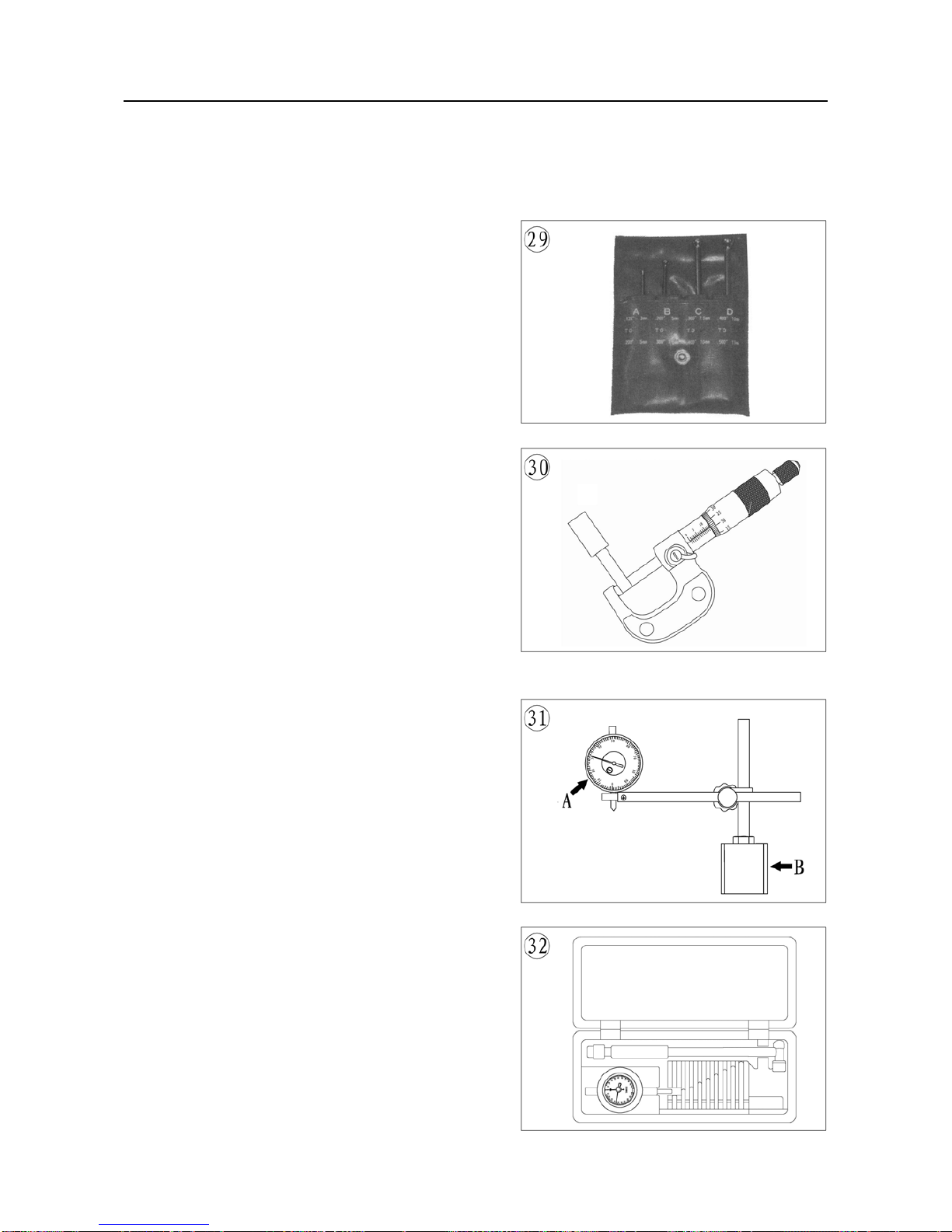
Use telescoping gauges (Figure 28) and small bore gauges (Figure 29) to measure bores.
Neither gauge has a scale for direct readings. Use an outside micrometer to determine the reading.
To use a telescoping gauge, select the correct
size gauge for the bore. Compress the movable post
and. Care fully insert the gauge into the bore. Carefully
move the gauge in the bore to make sure it is centered.
Tighten the knurled end of the gauge to hold the
movable post in position. Remove the gauge and
measure the length of the posts. Telescoping gauges
are typically used to measure cylinder bores.
To use a small bore gauge, select the correct size
gauge for the bore. Carefully insert the gauge into the
bore. Tighten the knurled end of the gauge to carefully
expand the gauge fingers to the limit within the bore.
Do not over tighten the gauge because there is no
built-in release. Excessive tightening can damage the
bore surface and damage the tool. Remove the gauge
and measure the outside dimension (Figure 30).
Small bore gauges are typically used to measure
valve guides.
Dial Indicator:
A dial indicator (Figure 31) is a gauge with a dial
face and needle used to measure variations in
dimensions and movements. Measuring brake rotor
runout is a typical use for a dial indicator.
Dial indicators are available in various ranges and
graduations and with three basic types of mounting
bases: magnetic (B. Figure 31). Clamp, or screw-in
stud. When purchasing a dial indicator, select on with
a continuous dial (A, Figure 31).
Cylinder Bore Gauge
A cylinder bore gauge is similar to a dial indicator.
The gauge set shown in Figure 32 consists of a dial
indicator, handle, and dif ferent length adapters (anvils)
to fit the gauge to various bore sizes. The bore gauge
is used to measure bore size, taper and out-of-round.
When using a bore gauge, follow the manufacturer’s
instructions.
Page 35
GENERAL INFORMATION
1-23
Compression Gauge
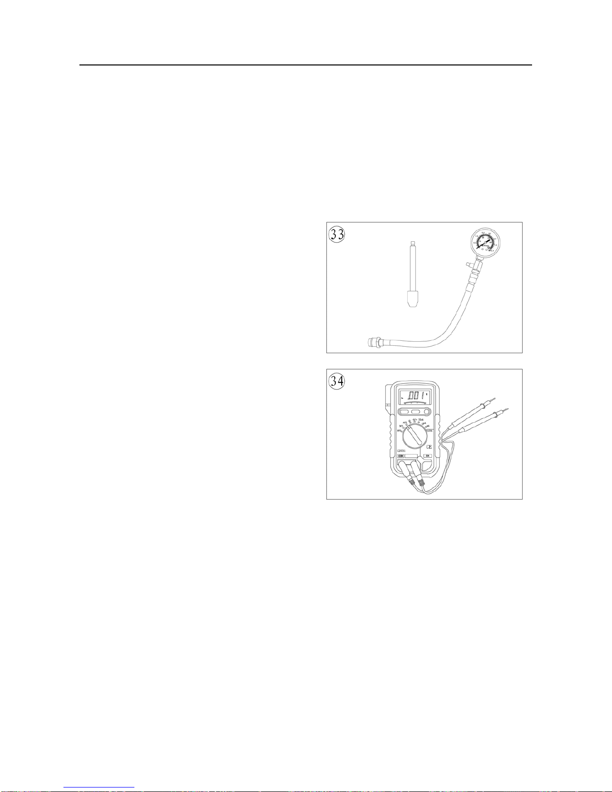
A compression gauge (Figure 33) measures combustion chamber (cylinder) pressure, usually in
psi or kg/ cm
2
. The gauge adapter is either inserted or screwed into the spark plug hole to obtain the
reading. Disable the engine so it does not start and hold the throttle in the wide-open position when
performing a compression test An engine that does not have adequate compression cannot be
properly tuned. Refer to Chapter Three.
Multimeter
A multimeter (Figure 34) is an essential tool for
electrical system diagnosis. The voltage function
indicates the voltage applied or available to various
electrical components. The ohmmeter function tests
circuits for continuity, or lack of continuity, and
measures the resistance of a circuit.
Some manufacturer’s specifications for electrical
components are based on results using a specific test
meter. Results may vary if using a meter not
recommended by the manufacturer. Such
requirements are noted when applicable.
Ohmmeter (analog) calibration
Each time an analog ohmmeter is used or if the
scale is changed, the ohmmeter must be calibrated.
Digital ohmmeters do not require calibration.
1. Make sure the meter battery is in good condition.
2. Make sure the meter probes are in good condition.
3. Touch the two probes together and observe the
needle location on the ohms scale. The needle
must Align with the 0 mark to obtain accurate
measurements.
4. If necessary, rotate the meter ohms adjust knob until the needle and 0 mark align.
ELECTRICAL SYSTEM FUNDAMENTALS
A thorough study of the many types of electrical systems used in today’s motorcycles is beyond
the scope of this manual. However, a basic understanding of electrical basics is necessary to perform
simple diagnostic tests.
Refer to Electrical Testing in Chapter Two for typical test procedures and equipment. Refer to
Chapter Ten for specific system test procedures.
Page 36

GENERAL INFORMATION
1-24
Voltage
Voltage is the electrical potential or pressure in an electrical circuit and is expressed in volts. The
more pressure (voltage) in a circuit the more work can be performed.
Direct current (DC) voltage means the electricity flows in one direction. All circuits powered by a
battery are DC circuits.
Alternating current (AC) means the electricity flows in one direction momentarily and then
switches to the opposite direction. Alternator output is an example of AC voltage. This voltage must be
changed or rectified to direct current to operate in a battery powered system.
Resistance
Resistance is the opposition to the flow of electricity within a circuit or component and is
measured in ohms. Resistance causes a reduction in available current and voltage
Resistance is measured in an inactive circuit with an ohmmeter. The ohmmeter sends a small
amount of current into the circuit and measures how difficult it is to push the current through the circuit.
An ohmmeter, although useful, is not always a good indicator of a circuit’s actual ability under
operating conditions. This is because of the low voltage (6-9 volts) the meter uses to test the circuit.
The voltage in an ignition coil secondary winding can be several thousand volts. Such high voltage can
cause the coil to malfunction, even though it tests acceptable during a resistance test.
Resistance generally. Increases with temperature. Perform all testing with the component or
circuit at room temperature. Resistance tests performed at high temperatures may indicate high
resistance readings and cause unnecessary replacement of a component.
Amperage
Amperage is the unit of measurement for the amount of current within a circuit. Current is the
actual flow of electricity . The higher the current, the more work can be performed up to a given point. If
the current flow exceeds the circuit or component capacity, it will damage the system.
BASIC SERVICE METHODS
Most of the procedures in this manual are straightforward and can be performed by anyone
reasonably competent with tools. However, consider personal capabilities carefully before attempting
any operation involving major disassembly.
1. Front, in this manual, rdfers to the front of the UTV, The front of any component is the end closest
to the front the UTV. The left and right sides refer to the position of the parts as viewed by the rider
sitting on the seat facing forward.
2. Whenever servicing an engine or suspension component, secure the UTV in a safe manner.
3. Tag all similar parts for location and mark all mating parts for position. Record the number and
thickness of any shims when removing them. Identify parts by placing them in sealed and labeled
plastic sandwich bags.
4. Tag disconnected wires and connectors with masking tape and a marking pen. Do not rely on
Page 37

GENERAL INFORMATION
1-25
memory alone.
5. Protect finished surfaces from physical damage or corrosion. Keep gasoline and other chemicals
off painted surfaces.
6. Use penetrating oil on frozen or tight bolts. Avoid using heat where possible. Heat can warp, melt
or affect the temper of parts. Heat also damages the finish of paint and plastics.
7. When a part is a press fit or requires a special tool to remove, the information or type of tool is
identified in the text. Otherwise, if a part is difficult to remove or install, determine the cause before
proceeding.
8. To prevent objects or debris from falling into the engine, cover all openings.
9. Read each procedure thoroughly and compare the illustrations to the actual components before
starting the procedure. Perform the procedure in
10. Recommendations are occasionally made to refer service to a dealership or specialist. In these
cases, the work can be performed more economically by the specialist than by the home
mechanic.
11. The term replaces means to discard a defective part and replace it with a new part. Overhaul
means to remove, disassemble, inspect, measure, repair and/or replace parts as required to
recondition an assembly.
12. Some operations require using a hydraulic press. If a press is not available, have these operations
performed by a shop equipped with the necessary equipment. Do not use makeshift equipment
that may damage the motorcycle.
13. Repairs are much faster and easier if the UTV is clean before starting work. Degrease the
motorcycle with a commercial degreaser; follow the directions on the container for the best results.
Clean all parts with cleaning solvent when removing them.
CAUTION
Do not direct high-pressure water at steering
bearings, fuel hoses, wheel bearings,
suspension and electrical components.
Water may force grease out of the bearings
and possibly damage the seals
14. If special tools are required, have them available before starting the procedure. When special
tools are required, they are described at the beginning of the procedure.
15. Make diagrams of similar-appearing parts. For instance, crankcase bolts are often not the same
lengths. Do not rely on memory alone. Carefully laid out parts can become disturbed, making it
difficult to reassemble the comports correctly.
16. Make sure all shims and washers are reinstalled in the same location and position.
17. Whenever rotating parts contact a stationary part, look for a shim or washer.
18. Use new gaskets if there is any doubt about the condition of old ones.
19. If using self-locking fasteners, replace them with new ones. Do not install standard fasteners in
place of self-locking ones.
20. Use grease to hold small parts in place if they tend to fall out during assembly. Do not apply
grease to electrical or brake components.
Page 38
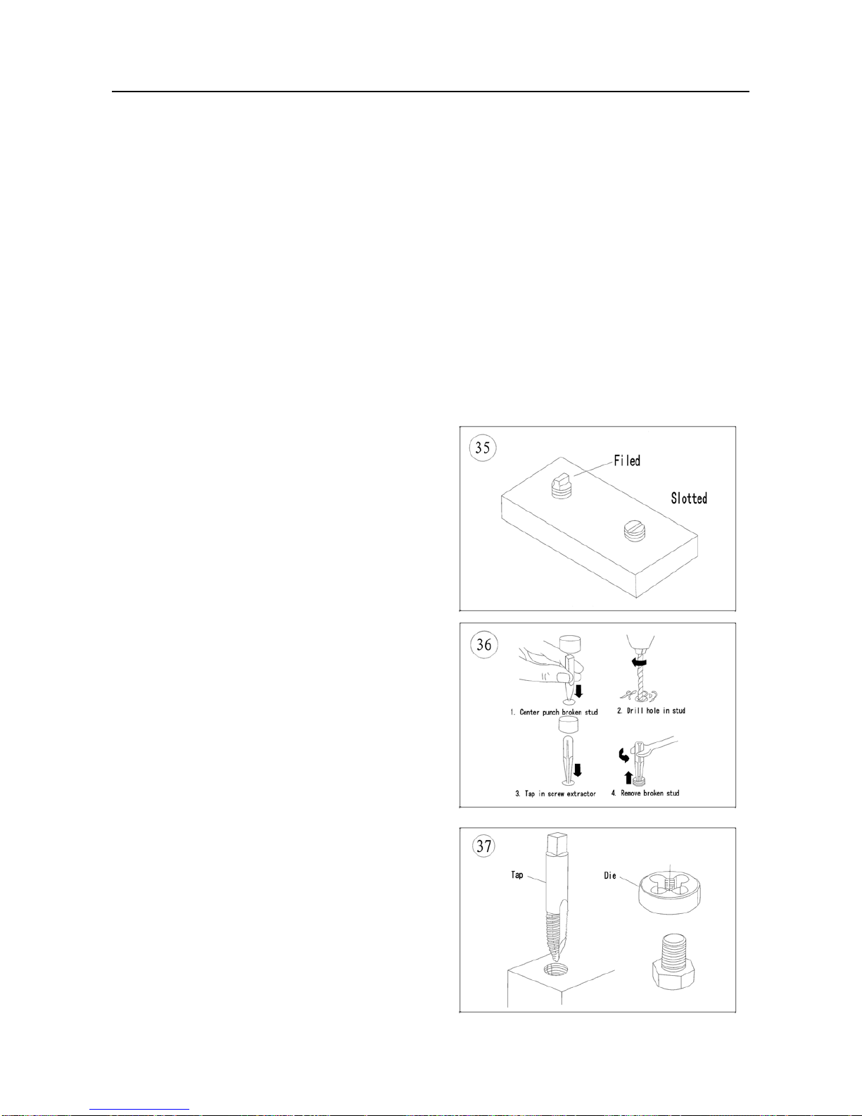
GENERAL INFORMATION
1-26
Removing Frozen Fasteners
If a fastener cannot be removed, several methods may be used to loosen it. First, apply a
penetrating fluid. Apply it liberally and let it penetrate for 10-15 minutes. Rap the fastener several times
with a small hammer. Do not hit it hard enough to cause damage. Reapply the penetrating fluid if
necessary.
For frozen screws, apply penetrating fluid as described, the insert a screwdriver in the slot and
rap the top of the screwdriver with a hammer. This loosens the rust so the screw can be removed in
the normal way. If the screw head is too damaged to use this method, grip the head with locking pliers
and twist the screw out.
Avoid applying heat unless specifically instructed. Heat may melt, warp or remove the temper
from parts.
Removing Broken Fasteners
If the head breaks off a screw or bolt, several
methods are available for removing the remaining
portion. If a large portion of the remainder projects out,
try gripping it with locking pliers. If the projecting
portion is too small, file it to fit a wrench of cut a slot in
it to fit a screwdriver (Figure 35)
If the head breaks off flush, use a screw extractor.
To do this, center punch the exact center of the
remaining portion of the screw or bolt. Drill a small
hole in the screw and tap the extractor into the hole.
Back the screw out with a wrench on the extractor
(Figure 36)
Repairing Damaged Threads
Occasionally, threads are stripped through
carelessness or impact damage. Often the threads
can be repaired by running a tap (for internal threads
on nuts) or die (for external threads on bolts) through
the threads (Figure 37). To clean or repair spark plug
threads, use a spark plug tap.
If an internal thread is damaged, it may be
necessary to install a Helical or some other type of
thread insert. Follow the manufacturer’s instructions
when installing their insert.
If it is necessary to drill and tap a hole, refer to
Table 8 for metric tap and drill sizes.
Page 39
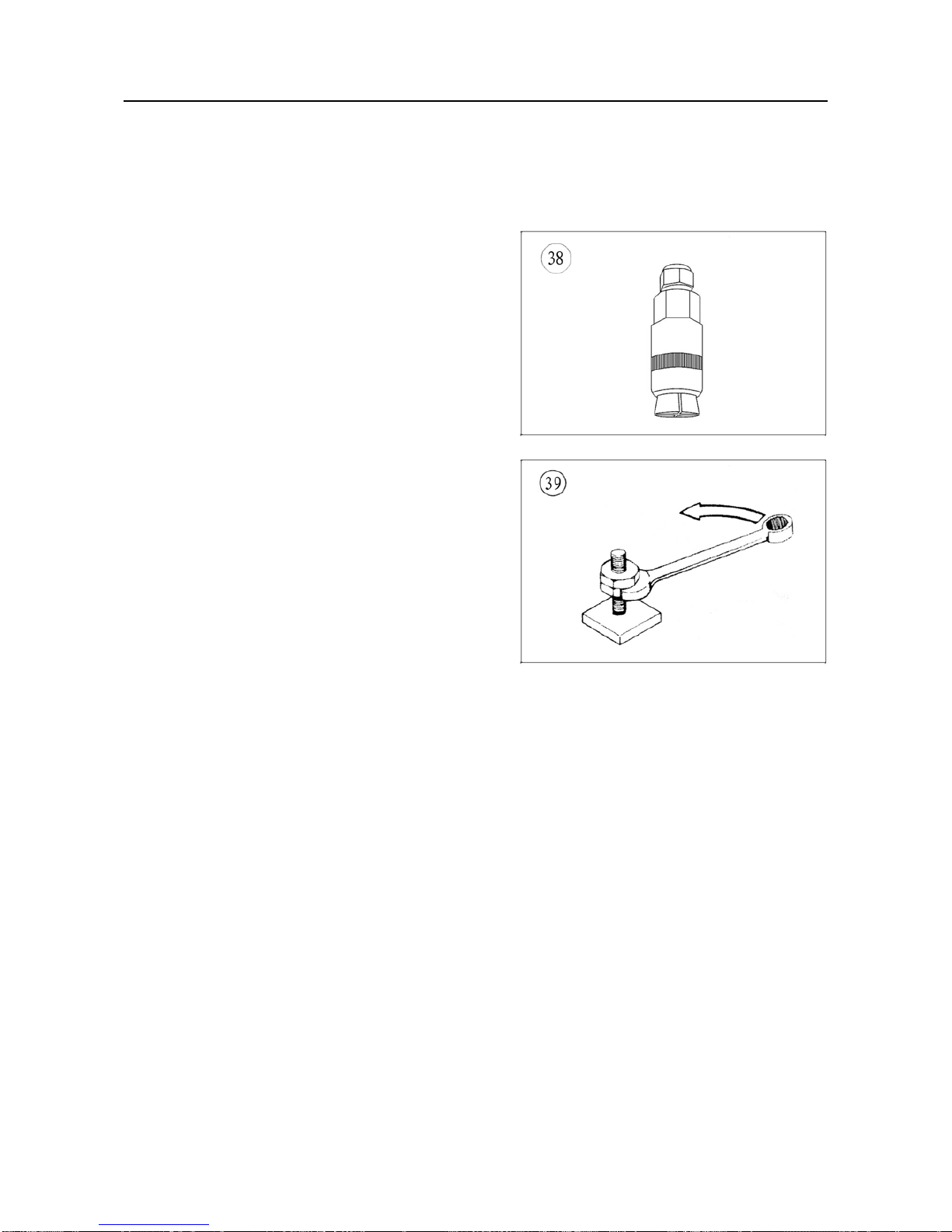
GENERAL INFORMATION
1-27
Stud Removal/ Installation
A stud removal tool (Figure 38) is available from most tool suppliers. This tool makes the removal
and installation of studs easier. If one is not available, thread two must onto the stud and tighten them
against each other. Remove the stud by turning the lower nut (Figure 39).
1. Measure the height of the stud above the
surface.
2. Thread the stud removal tool onto the stud and
tighten it, or thread two nuts onto the stud.
3. Remove the stud by turning the stud remover
or the lower nut.
4. Remove any thread locking compound from the
threaded hole. Clean the threads with an
aerosol parts cleaner.
5. Install the stud removal tool onto the new stud
or thread two nuts onto the stud.
6. Apply thread locking compound to the threads
of the stud.
7. Install the stud and tighten with the stud
removal tool or the top nut.
8. Install the stud to the height noted in Step 1 or
its torque specification.
9. Remove the stud removal tool or the two nuts.
Removing Hoses
When removing stubbor n hoses, do not exert excessive force on the hose or fitting. Remove the
hose, do not exert excessive force on the hose or fitting. Remove the hose clamp and carefully insert a
small screwdriver or pick tool between the fitting and hose. Apply a spray lubricant under the hose and
carefully twist the hose off the fitting. Clean the fitting of any corrosion or rubber hose material with a
wire brush Clean the inside of the hose thoroughly. Do not use any lubricant when installing the hose
(new or old). The lubricant may allow the hose to come off the fitting, even with the clamp secure.
Bearings
Bearings are used in the engine and transmission assembly to reduce power loss, heat and noise
resulting from friction. Because bearings are precision parts, they must be maintained with proper
lubrication and maintenance. If a bearing is damaged, replace it immediately. When installing a new
bearing, take care to prevent damaging it. Bearing replacement procedures are included in the
individual chapters where applicable; however. Use the following sections as a guideline.
NOTE
Unless otherwise specified, install
bearings with the manufacturer’s
Page 40
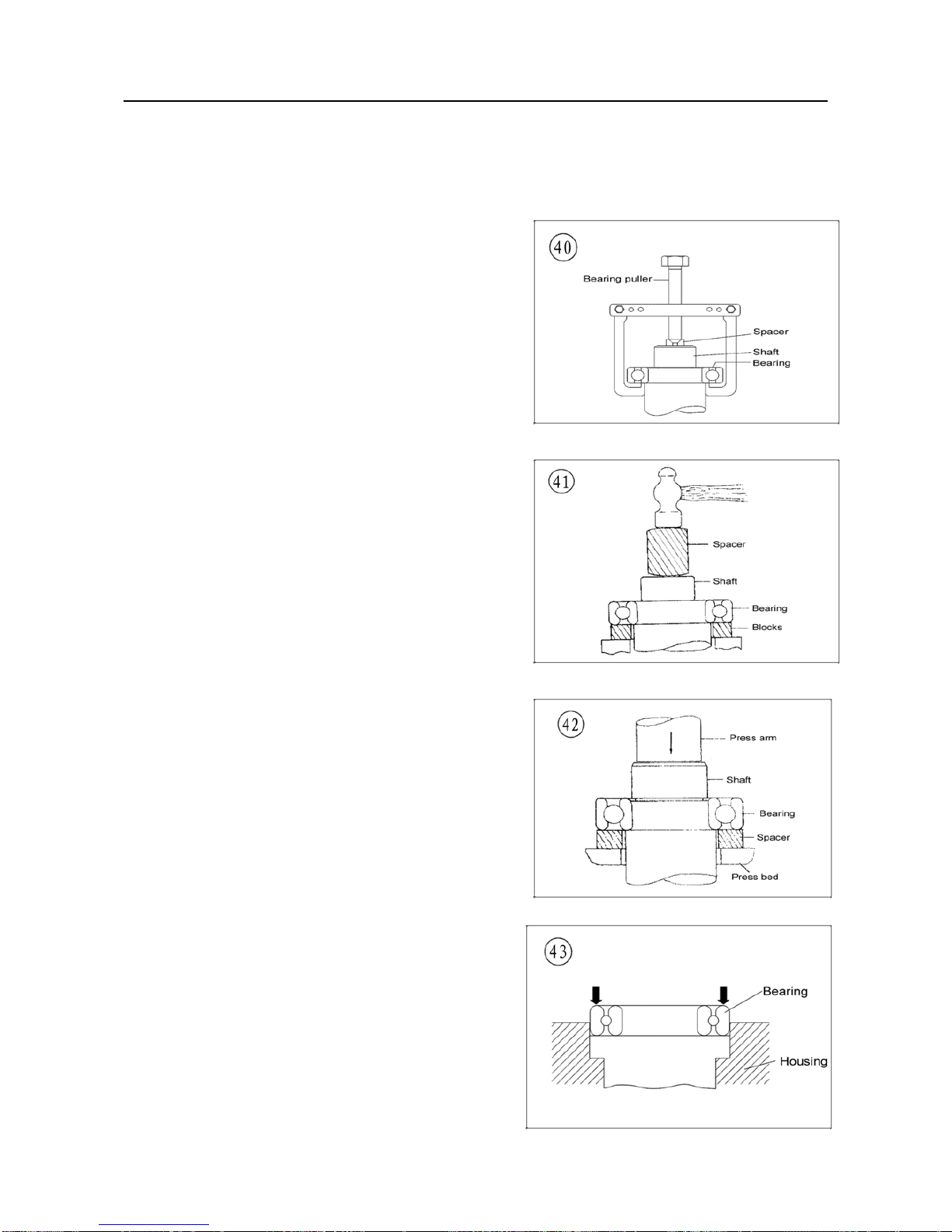
GENERAL INFORMATION
1-28
mark or number facing outward.
Removal
While bearing are normally removed only when
damaged, there may be times when it is necessary to
remove a bearing that is in good condition. However,
improper bearing removal will damage the bearing and
possibly the shaft or case. Note the following when
removing bearings:
1. When using a puller to remove a bearing from a
shaft, take care that the shaft is not damaged.
Always place a piece of metal between the end of
the shaft and the puller screw. In addition, place
the puller arms next to the inner bearing race. See
Figure 40.
2. When using a hammer to remove a bearing from a
shaft. do not strike the hammer directly against the
shaft. Instead, use a brass or aluminum rod
between the hammer and shaft (Figure 41) and
make sure to support both bearing races with
wooden blocks as shown.
3. The ideal method of bearing removal is with a
hydraulic press. Note the following when using a
press:
a. Always support the inner and outer bearing
races with a suitable size wooden or
aluminum spacer (Figure 42). If only the
outer race is supported, pressure applie
against the balls and/or the inner race will
damage them.
b. Always make sure the press arm (Figure 42)
aligns with the center of the shaft. If the arm
is not centered, it may damage the bearing
and/or shaft.
c. The moment the shaft is free of the bearing.
It drops to the floor. Secure or hold the shaft
to prevent it from falling.
Installation
1. When installing a bearing in a housing, apply
pressure to the outer bearing race (Figure 43).
When installing a bearing on a shaft, apply pressure
Page 41
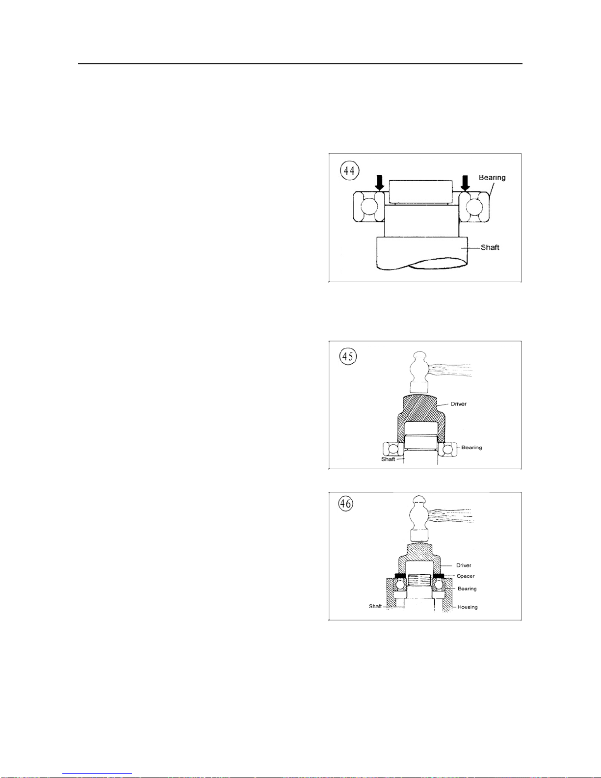
GENERAL INFORMATION
1-29
to the inner bearing race (Figure 44).
2. When installing a bearing as described in Step 1, some type of driver is required. Never strike the
bearing directly with a hammer or it will damage the bearing. When installing a bearing, use a
piece of pipe or a driver with a diameter that matches the bearing inner race. Figure 45 Shows
the correct way to use a driver and hammer to install a bearing.
3. Step 1 describes how to install a bearing in a
case half or over a shaft However, when installing
a bearing over a shaft and into the housing at the
same time, a tight fit is required for both outer and
inner bearing races. In this situation, install a
spacer underneath the driver tool so that pressure
is applied evenly across both races. See Figure
46. If the outer race is not supported as shown,
the balls will push against the outer bearing race
and damage it
Interference fit
1. Follow this procedure when installing a bearing
over a shaft. When a tight fit is
required, the
bearing inside diameter is smaller than the shaft.
In this case. Driving the bearing on the shaft using
normal methods may cause bearing damage.
Instead, heat the bearing before installation. Note
the following:
a. Secure the shaft so it is ready for bearing
installation.
b. Clean all residues from the bearing surface
of the shaft. Remove burrs with a file or
sandpaper.
c. Fill a suitable pot or beaker with clean
mineral oil. Place a thermometer rated
above 120℃(248°F) in the oil. Support the
thermometer so it does not rest on the
bottom or side of the pot.
d. Remove the bearing from its wrapper and
secure it with a piece of heavy wire bent to
hold it in the pot. Hang the bearing in the
pot so it does not touch the bottom or sides
of the pot.
e. Turn the heat on and monitor the thermometer. When the oil temperature rises to
approximately 120℃(248°F), remove the bearing from the pot and quickly install it. If
necessary, place a socket on the inner bearing race and tap the bearing into place. As the
bearing chills, it will tighten on the shaft, so install it quickly. Make sure the bearing is
installed completely.
Page 42

GENERAL INFORMATION
1-30
2. Follow this step when installing a bearing in a housing. Bearings are general installed in a housing
with a slight interference fit Driving the bearing into the housing using normal methods may
damage the housing or cause bearing damage. Instead, heat the housing before the bearing is
installed. Note the following:
CAUTION
Before heating the housing in this procedure, wash
the housing thoroughly with detergent and water.
Rinse and rewash the cases as required to remove
all traces of oil and other chemical deposits
a. Heat the housing to approximately 100 ℃ (212°F) in an oven or on a hot pla te. An easy way to
check that it is the proper temperature is to place tiny drops of water on the housing; if they
sizzle and evaporate immediately, the temperature is correct. Heat only one housing at a time.
CAUTION
Do not heat the housing with a propane or
acetylene torch. Never bring a flame into contact
with the bearing or housing. The direct heat will
destroy the case hardening of the bearing and will
likely warp the housing.
b. Remove the housing from the oven or hot plate, and hold onto the housing with welding gloves.
It is hot!
NOTE
Remove and install the bearings with a suitable
size socket and extension.
c. Hold the housing with the bearing side down and tap the bearing out. Repeat for all bearings in
the housing.
d. Before heating the bearing housing, place the new bearing in a freezer if possible. Chilling a
bearing slightly reduces its outside diameter while the heated bearing housing assembly is
slightly larger due to heat expansion. This makes bearing installation easier.
NOTE
Always install bearings with the manufacturer’s
mark or number facing outward.
e. While the housing is still hot. Install the new bearing(s) into the housing. Install the bearings by
hand. if possible. If necessary, lightly tap the bearing(s) into the housing with a driver placed on
the outer bearing race (Figure 43). Do not install new bearings by driving on the inner-bearing
race. Install the bearing(s) until it seats completely.
Page 43
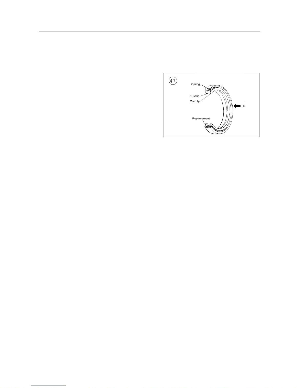
GENERAL INFORMATION
1-31
Seal Replacement
Seals (Figure 47) contain oil, water, grease or combustion gasses in a housing or shaft.
Improperly removing a seal can damage the housing or shaft. Improperly installing the seal can
damage the seat. Note the following:
1. Prying is generally the easiest and most effective
method of removing a seal from the housing.
However. Always place a rag underneath the pry
tool to prevent damage to the housing. Note the
seal’s installed depth or if it is installed flush.
2. Pack waterproof grease in the seal lips before the
seal is installed.
3. In most cases, install seals with the
manufacturer’s numbers or marks facing out.
4. Install seals with a socket or driver placed on the
outside of the seal as shown in. Drive the seal squarely into the housing until it is to the correct
depth or flush as noted during removal. Never install a seal by hitting against the top of it with a
hammer.
STORAGE
Several months of non-use can cause a general deterioration of the motorcycle, UTV This is
especially true in areas of extreme temperature variations. This deterioration can be minimized with
careful preparation for storage. A properly stored motorcycle is much easier to return to service.
Storage Ar ea Selection
When selecting a storage area, consider the following:
1. The storage area must be dry. A heated area is best, but not necessary. It should be insulated to
minimize extreme temperature variations.
2. If the building has large window areas, mask them to keep sunlight off the UTV .
3. Avoid buildings in industrial areas where corrosive emissions may be present. Avoid areas close to
saltwater.
4. Consider the area’s risk of fire, theft or vandalism. Check with an insurer regarding UTV coverage
while in storage.
Preparing the Motorcycle for Storage
The amount of preparation a motorcycle should undergo before storage depends on the expected
length of non-use, storage area conditions and personal preference. Consider the following list the
minimum requirement:
1. Wash the UTV thoroughly. Make sure all dirt, mud and other debris are removed.
Page 44

GENERAL INFORMATION
1-32
2. Lubricate the drive chain.
3. Start the engine and allow it to reach operating temperature. Drain the engine oil regardless of the
riding time since the last service. Fill the engine with the recommended type of oil.
4. Drain the fuel tank, fuel lines and carburetor.
5. Remove the spark plug and ground the ignition system with a grounding tool as described in this
chapter. Then pour a teaspoon (15-20ml) of engine oil into the cylinder. Place a rag over the
opening and Start the engine over to distribute the oil. Remove the grounding tool and reinstall the
spark plug.
6. When the engine has cooled to room temperature, drain the cooling system drain the coolant in
the coolant reserve tank and all tank lines.
7. Cover the exhaust and intake opening.
8. Apply a protective substance to the plastic and rubber components. Make sure to follow the
manufacturer’s instructions for each type of product being used.
9. Place the UTV on a work stand with both wheels off the ground.
10. Cover the UTV with old bed sheets or something similar. Do not cover it with any plastic material
that will trap moisture.
Returning the UTV to Service
The amount of service required when returning a UTV to service after storage depends on the
length of non-use and storage conditions. In addition to performing the reverse of the procedure, note
the following:
1. Remove the covers from the intake and exhaust openings.
2. Service the air filter as described in Chapter Three.
3. Inspect the cooling system. Check the drain plug and hose connections for leaks.
4. Refill the fuel tank. Turn the fuel shutoff valve on and check for fuel leaks.
5. Make sure the brakes, clutch, throttle and engine stop switch work properly before operating the
UTV. Evaluate the service intervals to determine which areas require service.
6. If the UTV has been in storage for longer than four months, change the engine oil as and filter, and
the transmission oil as described
Page 45

GENERAL INFORMATION
1-33
CHAPTER TWO
TROVBLESHOOTING
Diagnose electrical and mechanical problems by following an orderly procedure and remembering
the basic operating requirements
Define
→
Symptoms
↓
Determine
→
Which areas could exhibit these symptoms
↓
Test and analyze
→
The suspect areas
↓
Is date
→
The problem
By following a systematic approach, the possibility of unnecessary parts replacement can be
avoid, always start with the simple and most obvious checks when troubleshooting, This would include
the engine stop switch, fuel quantity and condition, fuel vale position and spark plug cap tightness
Proper maintenance as described in Chapter Three reduces the necessity for troubleshooting.
Even with the best of care, however, the motorcycle may develop problems that require trouble
shooting.
If the problem cannot be solved. Stop and evaluate all conditions prior to the problem. If the
motorcycle must be taken to a repair facility, the mechanic will want to know as many details as
possible.
For removal, installation and test procedures for some components, refer to the specific chapter.
When applicable, tables at the end of each chapter also provide specifications and service limits.
Page 46
GENERAL INFORMATION
1-34
ENGINE PRINCIPLES AND OPERATING REQUIREMENTS
An engine needs three basics to run properly:
Correct air/fuel mixture
Compression Engine runs
A spark at the right time
If one basic requirement is missing the engine will not run.
STARTING THE ENGINE
When experiencing engine-starting troubles, it is easy to work out of sequence and forget basic
starting procedures. The following sections describe the recommended starting procedures.
Engine is cold
1. Shift the transmission into neutral.
2. Turn the fuel valve on or confirm if the fuel is in upper or below retile in the fuel tank.
3. If the air temperature is below 0℃(32°F):
Open the throttle two or three time to allow the acceleration pump to feed additional fuel to the
engine.
If the air temperature is below 35℃ (95℃) pull the choke knob all the way out to richen the
air/fuel mixture.
4. When the engine starts, allow it to idle for approximately one minute, then push the choke all the
way in. If the idle is smooth, use the throttle to keep the engine running until it warms up.
NOTE
Do not race the engine during the warm\up
period. The carburetor accelerator pump can
overly richen the air/fuel mixture, which would
cause the engine to stall.
Engine is warm
1. Shift the transmission into neutral.
2. Confirm if the fuel is in upper or below retied in the tank.
3. Release the hot start lever as soon as the engine starts.
Page 47

GENERAL INFORMATION
1-35
Starting the engine after a fall or after the engine stalls
1. Shift the transmission into neutral.
2. Release the hot start lever as the engine starts.
3. If the engine fails to start, refer to Flooded Engine in this section.
Flooded engine
If the engine fails to start after several attempts, it is probably flooded. This occurs when too much
fuel is drawn into the engine and the spark plug fails to ignite it. The smell of gasoline is often evident
when the engine is flooded. Troubleshoot a flooded engine as follows:
1. Look for gasoline overflowing from the carburetor or overflow hose. If gasoline is evident, the
engine is flooded and/or the float in the carburetor bowl is stuck. If the carburetor float is stuck,
remove and repair the float assembly Shift the transmission into neutral.
2. Check that the chock knob is fully closed (pushed in).
3. Open the throttle fully and hold in this position. Then start the engine firmly through its entire
stoke ten times to clear the engine. Close the throttle.
4. Release the hot start lever as soon as the engine starts.
5. If the engine still does not start, refer to Engine will Not Start this chapter.
Engine cold with air temperature
Between 10-35℃(50-95°F)
1. Shift the transmission into neutral.
2. Turn the fuel valve on.
3. Pull the choke knob all the way out to richen the air/fuel mixture.
4. When the engine starts, allow it to idle for approximately 15 seconds, then push the choke all the
way. If the idle is not smooth, use the throttle to keep the engine running until it warms up.
NOTE
Do not race the engine during the warm-up
period. The carburetor accelerator pump can
overly richen the air/fuel mixture, which may cause
the engine to stall.
Engine cold with air temperature above 35℃(95°F)
1. Shift the transmission into neutral.
2. Turn the fuel valve on.
3. When the engine starts, allow it to idle until it warms up.
Page 48

GENERAL INFORMATION
1-36
Cold engine with air temperature below 10℃(50°F)
1. Shift the transmission into neutral.
2. Turn the fuel valve on
3. If the temperature is below 32°F (0℃), open the throttle two or three times to allow the accelerator
pump to feed additional fuel to the engine.
4. Pull the choke knob all the way out to richen the air/fuel mixture.
NOTE
Do not open the throttle when starting the engine
in Step 4. This will allow the accelerator pump to
feed more fuel to the engine, possibly causing
the spark plug to foul.
4. When the engine starts, use the throttle to keep the engine running until th
e engine warms up and
the choke can be fully closed.
NOTE
Do not race the engine during the warm-up
period. The carburetor accelerator pump can
overly richen the air/fuel mixture and cause the
engine to stall.
Engine is hot
1. Shift the transmission into neutral.
2. Turn the fuel valve on
NOTE
Do not open the throttle when starting the engine
in Step 3. This will allow the accelerator pump to
feed more fuel to the engine, possibly fouling the
spark plug.
3. Pull the hot start lever. Then while keeping the throttle closed, pull the clutch lever fully in and press
the starter button.
4. Release the hot start lever as soon as the engine starts.
Starting the engine after a fall or after the engine stalls
1. Shift the transmission into neutral.
2. Pull the hot start lever. Then while keeping the throttle closed.
3. Release the hot start lever as soon as the engine starts.
Page 49

GENERAL INFORMATION
1-37
4. If the engine fails to start, refer to Flooded Engine in this section.
Flooded engine
If the engine fails to start after several attempts, it is probably flooded. This situation occurs when
too much fuel is drawn into the engine and the spark plug fails to ignite it. The smell of gasoline is often
evident when the engine is flooded. Troubleshoot a flooded engine as follows:
1. Look for gasoline overflowing from the carburetor or overflow hose. If gasoline is evident, the engine
is flooded and/or the float in the carburetor bowl is stuck. If the carburetor float is stuck, remove and
repair the float assembly.
2. Shift the transmission into neutral.
3. Check that the choke knob is fully closed (pushed in).
4. Starter---Perform the following:
a. Pull the hot start lever, then pull the clutch lever fully in, open the throttle fully and press the
starter button for 5 seconds.
b. If the engine starts, close the throttle and release the hot start lever. If the engine starts but idles
roughly, vary the throttle position slightly until the engine idles and responds smoothly.
c. If the engine still does not start, refer to Engine Will Not Start in this chapter.
ENGINE WILL NOT START
Identifying the Problem
If the engine does not start, perform the following steps in order while remembering the Engine
Principals and Operating Requirements described in this chapter. If the engine fails to start after
performing these checks, refer to the troubleshooting procedures indicated in the steps. If the engine
starts, but idles or runs roughly, refer to Poor Engine Performance in this chapter.
1. Refer to Starting the Engine in this chapter to make sure all starting procedures are correct.
2. If the engine seems flooded, refer to Starting The Engine in this chapter. If the engine is not flooded,
continue with Step 3.
3. Remove the cap from the fuel tank and make sure the fuel tank and make sure the fuel tank has a
sufficient amount of fuel to start the engine.
4. If there is sufficient fuel in the fuel tank, remove the spark plug immediately after attempting to start
the engine. The plug’s insulator should be wet, indicating that fuel is reaching the engine. If the plug
tip is dry, fuel is not reaching the engine. Refer to Fuel System in this chapter. If there is fuel on the
spark plug and the engine will not start, the engine may not have adequate spark. Continue with
Step
5.
5. Make sure the direct ignition coil or spark plug wire is secure. Push the direct ignition coil or spark
plug cap and slightly rotate it to clean the electrical connection between the plug and the connector.
If the engine does not start. Continue with step 6
Page 50

GENERAL INFORMATION
1-38
NOTE
A cracked or damaged direct ignition coil or spark plug
cap and cable can cause intermittent problems that are
difficult to diagnose. If the engine occasionally misfires
or cuts out, use a spray bottle to wet the direct ignition
coil or plug cap and plug cable while the engine is
running. Water that enters one of theses areas causes
an arc through the insulating material, causing an
engine misfire.
NOTE
Engine misfire can also be caused by water that enters
through connectors. Check the connectors for loose wire
ends. On waterproof connectors, check for damage
where the wires enter the connector.
6. Perform the Spark Test in this section. If there is a strong spark, perform Step 7. If there is no spark
or if the spark is very weak, refer to Ignition System Testing in Chapter Ten.
7. If the fuel and ignition systems are working correctly, perform a leakdown test (this chapter) and
cylinder compression test. If the leak down test indicates a problem, or the compression under
Engine in this chapter.
Spark Test
Perform a spark test to determine if the ignition system is producing adequate spark. This test
should be performed with a spark tester. A spark tester looks like a spark plug with an adjustable gap
between the center electrode and grounded base. Because the voltage required to jump the spark
tester gap is sufficiently larger than that of a normally gapped spark plug, the test results are more
accurate than with a spark plug. Do not assume that because a spark jumped across a spark plug gap,
the ignition system is working correctly.
Perform this test on the engine when it is both cold and hot, if possible. If the test results are positive
for each test, the ignition system is working correctly.
CAUTION
After removing the direct ignition coil or spark plug cap
and before removing the spark plug in Step 1, clean the
area around the spark plug with compressed air. Dirt
that falls into the cylinder causes rapid engine wear.
1. Disconnect the direct ignition coil or spark plug cap. Check for the presence of water.
2. Visually inspect the spark plug for damage.
3. Connect a spark tester to the direct ignition coil or spark plug cap. Ground the spark tester base (or
spark plug) to a good ground. Position the spark tester or spark plug firing tip away from the open
spark plug hole. Position the spark tester so the electrodes are visible.
Page 51

GENERAL INFORMATION
1-39
WARNING
Mount the spark tester or spark plug away from the
spark plug hole in the cylinder. If the engine is flooded,
do not perform this test. The spark tester can ignite fuel
ejected through the spark plug hole.
5. Shift the transmission into neutral.
WARNING
Do not hold the spark tester, spark plug or connector or
a serious electrical shock may result.
5. Turn the engine over using the starter and push the starter button. A fat blue spark must be evident
between the spark tester or spark plug terminals.
6. If there is a strong, blue spark, the ignition system is functioning properly, Check for one or more of
the following possible malfunctions:
a. Faulty fuel system component.
b. Flooded engine.
c. engine damage(low compression).
7. If the spark was weak (white or yellow) or if there was no spark, perform the peak voltage checks
described under Ignition System Testing.
8. Reinstall the fuel tank.
Starter Does Not Turn Over or Turns Over Slowly
Refer to Starting System Testing
POOR ENGINE PERFORMANCE
If the engine runs, but performance is unsatisfactory, refer to the following section that best
describes the symptoms.
Engine Starts But Stalls and is Hard to Restart
Check for the following:
1. Incorrect choke operation. This can be due to improper use or a stuck choke valve in the carburetor.
2. Incorrect hot start valve operation. This situation can be due to improper use or incorrect hot start
valve adjustment.
3. Plugged fuel tank went hose.
4. Plugged fuel hose. Fuel shutoff valve or fuel filter.
5. Incorrect carburetor adjustment.
Page 52

GENERAL INFORMATION
1-40
6. Incorrect float level adjustment.
7. Plugged carburetor jets.
NOTE
If a warm or hot engine will start with the choke on, or if a
cold engine starts and runs until the choke is turned off.
The pilot jet is probably plugged.
8. Contaminated or stale fuel.
9. Clogged air filter.
10. Intake pipe air leak.
11. Plugged exhaust system. Check the silencer or muffler, especially if the utility terrain vehicle was
just returned from storage.
12. Faulty ignition system component.
Engine Backfires, Cuts Out or Misfires During Acceleration
A backfire occurs when fuel is burned or ignited in the exhaust system.
1. A lean air/fuel mixture can cause these engine performance problems. Check for the following
conditions:
a. Incorrect float level adjustment.
b. Plugged pilot jet or pilot system.
2. Faulty accelerator pump.
3. Loose exhaust pipe-to-cylinder head connection.
4. Intake air leak.
5. Incorrect ignition timing or a damaged ignition system can cause these conditions. Perform the Peak
Voltage Tests to isolate the damaged ignition system component. Check the ignition timing as
described.
NOTE
The ignition timing is controlled by the ICM and cannot
be adjusted. However, checking the ignition timing can
be used to diagnose problems.
6. Check the following engine components:
a. Broken valve springs.
b. Stuck or leaking valves.
c. Worn or damaged camshaft lobes.
d. Incorrect valve timing due to incorrect camshaft installation or a mechanical failure.
Engine Backfires on Deceleration
Page 53

GENERAL INFORMATION
1-41
If the engine backfires when the throttle is released, check the following:
1. Lean carburetor pilot system.
2. Loose exhaust pipe-to-cylinder head connection.
3. Faulty ignition system component.
4. Check the following engine components:
a. Broken valve springs.
b. Stuck or leaking valves.
c. Worn or damaged camshaft lobes.
d. Incorrect valve timing due to incorrect camshaft installation or a mechanical failure.
Poor Fuel Mileage
1. Clogged fuel system.
2. Dirty or clogged air filter.
3. Incorrect ignition timing.
Engine Will Not Idle or Idles Roughly
1. Clogged air filter element.
2. Poor fuel filter or fuel hose.
3. Faulty accelerator pump assembly.
4. Contaminated or stale fuel.
5. Incorrect carburetor adjustment.
6. Leaking head gasket.
7. Intake air leak.
8. Incorrect ignition timing
9. Low engine compression
Low Engine Power
1. Support the UTV in a stand with the rear wheel off the ground. then spins freely. If the wheel does
not spin freely. Check for the following conditions:
a. Dragging brakes. Check for this condition immediately after riding the UTV
NOTE
After riding the UTV. Come to a stop on a level surface.
Turn the engine off and shift the transmission into
neutral. Walk or push the UTV forward. If the UTV is
harder to push than normal. Check for dragging brakes
b. Damaged or binding drive system
c. Damaged drive system and gear bearing
Page 54

GENERAL INFORMATION
1-42
2. Test ride the UTV and accelerate quickly from first to second gear. If the engine speed in-creased
according to throttle position. Perform Step 3. If the engine speed did not increase. Check CVT
a. Warped clutch plates/discs
b. CVT spring
3. Test ride the UTV and accelerate lightly. If the engine speed increased according to throttle position.
Perform Step 4. If the engine speed did not increase. Check for one or more of the following
problems:
a. Clogged air filter
b. Restricted fuel flow
c. Pinched fuel tank breather hose (Figure 9).
d. Clogged or damaged silencer or muffler
NOTE
A clogged exhaust system will prevent some of the
burned exhaust gasses from exiting the exhaust port at
the end of the exhaust stroke. This condition effects the
incoming air/fuel mixture on the intake stroke and
reduces engine power
4. Check for retarded ignition timing. A decrease in power results when the plugs fire later than normal
5. Check for one or more of the following problems
a. Low engine compression
b. Worn spark plug
c. Fouled spark plug
d. Incorrect spark plug heat range
e. Weak ignition coil
f. Incorrect ignition timing
g. Plugged carburetor passages
h. Incorrect oil level (too high or too low)
i. Contaminated oil
j. Worn or damaged valve train assembly
k. Engine overheating
6. If the engine knocks when it is accelerated or when running at high speed. Check for one or more of
the following possible malfunctions:
a. Incorrect type of fuel
b. Lean fuel mixture
c. Advanced ignition timing
NOTE
Other signs of advanced ignition timing are engine
overheating and hard or uneven engine starting
d. Excessive carbon buildup in combustion chamber
e. Worn pistons and/or cylinder bores
Page 55

GENERAL INFORMATION
1-43
Poor Idle or Low Speed Performance
1. Check for an incorrect pilot screw adjustment
2. Check for damaged or loose intake pipe and air filter housing hose clamps. These
conditions will cause an air leak
3. Perform the spark test in this chapter. Note the following:
a. If the spark is good. Go to Step 4
b. If the spark is weak. Perform the Peak Voltage Testing
4. Check the ignition timing. If ignition timing is correct. Perform Step 5. If the timing is
incorrect. Perform the Peak Voltage Testing
5. Check the fuel system as described in this chapter
Poor High Speed Performance
1. Check ignition timing. If the ignition timing is correct. Perform Step 2. If the timing is incorrect.
Perform the Peak Voltage
2. Check the fuel system as described in this chapter
3. Check the valve clearance as described. Note the following:
a. If the valve clearance as correct. Perform Step 4
b. If the clearance is incorrect. adjust the valves as described in Chapter Three
4. Incorrect valve timing and worn or damaged valve springs can cause poor high-speed
performance. If the camshaft was timed just before the UTV experiencing this type of problem.
The cam timing may be incorrect. If the cam timing was not set or changed. And all the other
inspection procedures in this section failed to locate the problem. Inspect the camshaft and calve
assembly
FUEL SYSTEM
The following section isolates common fuel system problems under specific complaints. If there is a
good spark. Poor fuel flow may be preventing the correct amount of fuel from being supplied to the
spark plug. Troubleshoot the fuel system as follows:
1. Clogged fuel tank breather hose
2. Check that there is a sufficient amount of fuel in the rank
3. After attempting to start the engine. Remove the spark plug and check for fuel on the plug tip.
Note the following:
a. If there is no fuel visible in the plug. Check for a clogged fuel shutoff valve. Fuel filter or fuel
line
b. If there is fuel present on the plug tip. And the engine has spark. Check for an excessive
intake air leak or the possibility of contaminated or stale fuel
NOTE
If the UTV was not used for some time. And was not
properly stored. The fuel may have gone stale. Where
Page 56

GENERAL INFORMATION
1-44
lighter parts of the fuel have evaporated. Depending on
the condition of the fuel. a no-start condition can result
c. If there is an excessive amount of fuel on the plug. Check for a clogged air filter or flooded
carburetor.
Rich Mixture
The following conditions can cause a rich air/fuel mixture:
1. Clogged air filter
2. Choke valve stuck open
3. Float level too high
4. Contaminated float valve seat
5. Worn or damaged float valve and seat
6. Leaking or damaged float
7. Clogged carburetor jets
8. Incorrect carburetor jetting
Lean Mixture
The following conditions can cause a lean air/fuel mixture:
1. Intake air leak
2. Float level too low
3. Clogged fuel line, fuel filter or fuel shutoff valve
4. Partially restricted fuel tank breather hose
5. Plugged carburetor air vent hose
6. Damaged float
7. Damaged float valve
8. Incorrect carburetor jetting
ENGINE
Engine Smoke
The color of engine smoke can help diagnose engine problems or operating conditions
Black smoke
Black smoke is an indication of a rich air/fuel mixture
Page 57

GENERAL INFORMATION
1-45
Blue smoke
Blue smoke indicates that the engine is burning oil in the combustion chamber as it leaks past worn
valve stem seals and piston rings. Excessive oil consumption is another indicator of an engine that is
burning oil. Perform a compression test to isolate the problem.
White smoke or steam
It is normal to see white smoke or steam from the exhaust after first starting the engine in cold
weather. This is actually condensed steam formed by the engine during combustion. If the UTV is
ridden far enough, the water cannot collect in the crankcase and should not become a problem. Once
the engine heats up to normal operating temperature, the water evaporates and exits the engine
through the crankcase vent system. However, if the UTV is ridden for short trips or repeatedly started
and stopped and allowed to cool off without the engine getting warm enough, water will start to collect
in the crankcase. With each short run of the engine, more water collects. As this water mixes with the
oil in the crankcase, sludge is produced. Sludge can eventually cause engine damage as it circulates
through the lubrication system and blocks off oil passages.
Large amounts of steam can also be caused by a cracked cylinder head or cylinder block surface
that allows coolant to leak into the combustion chamber. Perform a Coolant System Pressure Test.
Low Engine Compression
Problems with the engine top end will affect engine performance. When the engine is suspect,
perform the leak down procedure in this chapter and make a compression test . Interpret the results as
described in each procedure to troubleshoot the suspect area. An engine can lose compression
through the following areas:
1. Valves:
a. Incorrect valve adjustment.
b. Incorrect valve timing.
c. Worn or damaged valve seat surfaces.
d. Bent valves.
e. Weak or broken valve springs.
2. Cylinder head:
a. Loose spark plug or damaged spark plug hole.
b. Damaged cylinder head gasket.
c. Warped or cracked cylinder head.
3. Damaged decompress or assembly.
High Engine Compression
1. Faulty decompress or assembly.
2. Excessive carbon buildup in the combustion chamber.
Page 58

GENERAL INFORMATION
1-46
Engine Overheating
(Cooling System)
WARNING
Do not remove the radiator cap, coolant drain plug or disconnect
any coolant hose immediately after or during engine operation.
Scalding fluid and steam may be blown out under pressure and
cause serious injury. When the engine has been operated, the
coolant is very hot and under pressure. Attempting to remove
the items when the engine is hot can cause the coolant to spray
violently from the radiator, water pump or hose, causing severe
burns and injury.
1. Low coolant level.
2. Air in cooling system.
3. Clogged radiator, hose or engine coolant passages.
4. Worn or damaged radiator cap.
5. Damaged water pump.
Engine Overheating
(Engine)
1. Improper spark plug heat range.
2. Low oil level.
3. Oil not circulating properly.
4. Valves leaking.
5. Heavy carbon deposits in the combustion chamber.
6. Dragging brake(s).
7. Slipping clutch.
Preignition
Preignition is the premature burning of fuel and is caused by hot spots in the combustion chamber.
Glowing deposits in the combustion chamber, inadequate Cooling or an overheated spark plug can all
cause preignition. This is first noticed as a power loss but eventually causes damage to the internal
parts of the engine because of the high combustion chamber temperature.
Page 59

GENERAL INFORMATION
1-47
Detonation
Detonation is the violent explosion of fuel in the combustion chamber before the proper time of
ignition. Using low octane gasoline is a common cause of detonation.
Even when using a high octane gasoline, detonation can still occur. Other causes are
over-advanced ignition timing, lean air/fuel mixture at or near full throttle, inadequate engine cooling,
or the excessive accumulation of carbon deposits in the combustion chamber.
Continued detonation can result in engine damage.
Power Loss
Refer to Poor Engine Performance in this chapter.
Engine Noises
Unusual noises are often the first indication of a developing problem. Investigate any new noises
as soon as possible. Something that may be a minor problem, if corrected, could prevent the
possibility of more extensive damage.
Use a mechanic’s stethoscope or a small section of hose held near your ear (not directly on your
ear) with the other end close to the source of the noise to isolate the location. Determining the exact
cause of a noise can be difficult. If this is the case, consult with a professional mechanic to determine
the cause. Do not disassemble major components until all other possibilities have been eliminated.
Consider the following when troubleshooting engine noises:
1. Knocking or pinging during acceleration can be caused by using a lower octane fuel than
recommended. May also be caused by poor fuel. Pinging can also be caused by an incorrect
spark plug heat range or carbon buildup in the combustion chamber.
2. Slapping or rattling noises at low speed or dur ing acceleration—May be caused by excessive
piston-to-cylinder wall clearance (piston slap).
NOTE
Piston slap is easier to detect when the engine is
cold and before the piston has expanded. Once
the engine has warmed up, piston expansion
reduces piston-to-cylinder clearance.
3. Knocking or rapping while decelerating—Usually caused by excessive rod bearing clearance.
4. Persistent knocking and vibration occurring every crankshaft rotation—Usually caused by
worn rod or main bearing(s). Can also be caused by broken piston rings or a damaged piston
pin.
5. Rapid on-off squeal—Compression leak around cylinder head gasket or spark plug(s).
6. Valve train noise—Check for the following:
Page 60

GENERAL INFORMATION
1-48
a. Excessive valve clearance.
b. Worn or damaged camshaft.
c. Damaged camshaft.
d. Worn or damaged valve train components.
e. Damaged valve lifter bore(s).
f. Valve sticking in guide.
g. Broken valve spring.
h. Low oil pressure.
i. Clogged cylinder oil hole or oil passage.
ENGLNE LUBRICATION
An improperly operating engine lubrication system quickly leads to engine seizure. Check the
engine oil level and oil pressure.
High Oil Consumption or Excessive
Exhaust Smoke
1. Worn valve guides.
2. Worn valve guide seals.
3. Worn or damaged piston rings.
4. Incorrect piston ring installation.
Low Oil Pressure
1. Low oil level.
2. Worn or damaged oil pump.
3. Clogged oil strainer screen.
4. Clogged oil filter.
5. Internal oil leakage.
6. Oil relief valve stuck open.
7. Incorrect type of engine oil.
High Oil Pressure
1. Oil relief valve stuck closed.
2. Clogged oil filter.
3. Clogged oil gallery or metering orifices.
Page 61

GENERAL INFORMATION
1-49
No Oil Pressure
1. Low oil level.
2. Oil relief valve stuck closed.
3. Damaged oil pump.
4. Incorrect oil pump installation.
5. Internal oil leak.
Oil Level Too Low
1. Oil level not maintained at correct level
2. Worn piston rings.
3. Worn cylinder.
4. Worn valve guides.
5. Worn valve guide seals.
6. Piston rings incorrectly installed during engine overhaul.
7. External oil leakage.
8. Oil leaking into the cooling system.
Oil Contamination
1. Blown head gasket allowing coolant to leak into the engine.
2. Coolant leak.
3. Oil and filter not changed at specified intervals or when operating conditions demand more
frequent changes.
CYLINDER LEAKDOWN TEST
A cylinder leakdown test can accurately pinpoint engine leakage problems from the head gasket,
water jackets in the cylinder head and cylinder, valves and valve seats, and piston rings. This test is
performed by applying compressed air to the cylinder through a special tester and then measuring the
percent of leakage. A cylinder leakdown tester and an air compressor are needed to perform this test.
When performing a leakdown test, the engine is first set at TDC on its compression stroke so that
all the valves are closed. When the combustion chamber is pressurized, very little air should escape.
However, the difficulty in performing a leakdown test on a single cylinder engine(especially on the
engines described in this manual with low static engine compression) is in preventing the piston from
moving as the combustion chamber starts to pressurize. Any piston movement will force the crankshaft
to turn away from TDC and allow air to escape past an open valve seat.
In this procedure it will be necessary to lock the engine at TDC on its compression stroke and
then perform the leakdown test. Follow the manufacturer’s directions along with the follow the
manufacturer’s directions along with the following information when performing a cylinder leakdown
test.
Page 62

GENERAL INFORMATION
1-50
1. Support the UTV on a work stand with the rear wheel off the ground.
2. Remove the air filter assembly Open and secure the throttle so it is at its wide-open position.
3. Remove the spark plug.
4. Install the threaded hose adapter from the leakdown kit. Then install the leakdown gauge onto
the hose.
5. Remove the ignition timing hole cap from the left crankcase cover.
6. Remove the crankshaft hole cap from the right crankcase cover.
NOTE
Because the following test is performed with the cylinder head
cover installed on the engine, the camshaft lobes cannot be
viewed to ensure that the engine is positioned at TDC on its
compression stroke. To determine when the engine is
approaching TDC on its compression stroke, or whether it is
360°off. Observe the following two indicators to predict engine
position. First, when aligning the index marks in Step7, listen for
pressure building inside the combustion chamber. Indicating
that the piston is moving to TDC on its compression stroke.
Second, view the gauge on the leakdown tester when turning
the engine. As the piston moves toward TDC on its compression
stroke, compression building inside the combustion chamber
may cause the gauge needle to move slightly. If the crankshaft
is 360°off, these indicators will not be present.
NOTE
The decompress or mechanism will click loudly once during
each crankshaft revolution. This is normal.
7. Use hex socket on the primary drive gear mounting bolt and turn the crankshaft clockwise and align
the TDC mark on the flywheel with the index mark on the left crankcase cover Remove the hex socket
from the primary drive gear.
8. Perform the following to lock the transmission so the engine remains at TDC on
its compression
stroke when performing the leakdown test:
WARNING
Do not attempt to lock the engine by trying to use a tool to
hold the Allen bolt on the end of the crankshaft. Once the
combustion chamber becomes pressurized, any
crankshaft movement can throw the tool away from the
engine under considerable force, attempting to hole the
tool can cause serious injury. Engine damage may also
occur to the crankshaft or right crankcase cover. Lock the
engine as described in this procedure.
Page 63

GENERAL INFORMATION
1-51
a. Turn the drive sprocket by hand and shift the transmission into top gear with the shift pedal.
b. Mount a holding tool or equivalent onto the drive sprocket. Use a wooden block and clamp to
hold the holding tool so it cannot move when the combustion chamber becomes pressurized.
c. Check that the TDC marks are still aligned as described in Step7,
If not, turn the crankshaft as required, then relock the holding tool in position.
9. Remove the radiator cap and the oil filler cap.
10. Perform a cylinder leakdown test by applying air pressure to the combustion chamber. Follow the
manufacturer’s instructions while reading the percent of leakage on the gauge. Listen for air
leaking while noting the following:
NOTE
Because of play in the transmission gears, it is unlikely the
engine will stay at TDC on the first try If the crankshaft turns,
reposition the countershaft slightly and then relock it in
position with the holding tool. After several attempts, you will
get a feel of the transmission play and know what direction the
countershaft should be turned and locked.
NOTE
If a large amount of air escapes from the exhaust pipe or
through the carburetor, the air is leaking through on open
valve, Check the index mark to make sure the engine is at
TDC on the compression stroke, If the engine is remaining at
TDC but there is still a large amount of air escaping from the
engine, the crankshaft is off one revolution. Turn the engine
360°and realign the TDC mark as described in Step 7, then
relock it as described in Step8.
a. Air leaking through the exhaust pi pe indicates a leaking exhaust valve.
b. Air leaking through the carburetor indicates a leaking intake valve.
c. Air leaking through both the intake and exhaust valves indicates the engine is not set at
TDC on its compression stroke.
d. Air leaking through the coolant filler neck indicates a leaking cylinder head gasket or a
cracked cylinder head or cylinder liner.
e. Air leaking through the oil filler hole indicates the rings are not sealing properly in the
bore.
11. If the cylinder leakdown is 10 percent or higher, further service is required.
12. Disconnect the test equipment and install all the parts previously removed.
Page 64

GENERAL INFORMATION
1-52
ELECTRICAL TESTING
This section describes basic electrical testing and test equipment use.
Preliminary Checks and Precautions
Refer to the color wiring diagrams at the end of the manual for component and connector
identification, Use the wiring diagrams to determine how the circuit should work by tracing the current
paths from the power source through the circuit components to ground. Also, check any circuits that
share the same fuse (if used), ground or switch. If the other circuits work properly and the shared
wiring is good, the cause must be in the wiring used only by the suspect circuit. If all related circuits are
faulty at the same time, the probable cause is a poor ground connection or a blown fuse (if used).
As with all troubleshooting procedures, analyze typical symptoms in a systematic manner. Never
assume any thing and do not overlook the obvious like a blown fuse or an electrical connector that has
separated. Test the simplest and most obvious items first and try to make tests at easily accessible
points on the UTV.
Before starting any electrical troubleshooting, perform the following:
1. Check the fuse if the fuse is blown, replace it.
2. Inspect the battery. Make sure it is fully charged, and the battery leads are clean and securely
attached to the battery terminals.
3. Disconnect each electrical connector in the suspect circuit and make sure there are no bent
terminals in the electrical connector
4. Make sure the terminals on the end of each wire are pushed all the way into the connector. If not.
Carefully push them in with a narrow blade screwdriver
5. Check the wires where they connect to the terminals for damage
6. Make sure all terminals within the connector are clean and free of corrosion. Clean them. If
necessary. And pack the connectors with dielectric grease
7. Push the connectors with dielectric grease. The connectors are fully engaged and locked
together
8. Never pull the electrical wires when disconnecting an electrical connector-pull only on the
connector
Intermittent Problems
Intermittent problems are problems that do not occur all the time and can be difficult to locate. For
example. When a problem only occurs when the UTV is ridden over rough roads (vibration) or in wet
conditions (water penetration). It is intermit-ten. To locate and repair intermittent problems. Simulate
the condition when testing the compo-nets. Note the following:
1. Vibration---This is a common problem with loose or damaged electrical connectors
a. Perform a continuity test as described in the appropriate service procedure. Or under
Continuity Test in this section
b. Lightly pull or wiggle the connectors while repeating the test. Do the same when checking the
wiring harness and individual components. especially where the wires enter a housing or
Page 65

GENERAL INFORMATION
1-53
connector
c. A change in meter readings indicates a poor connection. Fine and repair the problem or
replace the part. Check for wires with cracked or broken insulation
NOTE
An analog ohmmeter is useful when making this
type of test. Slight needle movements are
apparent when indicating a loose connection
2. Heat – This is another common problem with connectors or plugs that have loose or poor
connections. As these connections heat up. The connection or joint expands and separates.
Causing an open circuit. Other heat related problem occur when a component creates its own
heat as it starts to fail or go bad
a. Troubleshoot the problem to help isolate the problem or area
b. To check a connector. Perform a continuity test as described in the appropriate service
procedure. Or under Continuity test in this chapter. Then repeat the test while heating the
ground. If the lamp comes on. The problem is the connection between the lamp and
Connector with a heat gun or hair dryer. If the meter reading was normal (continuity) when the
connector was cold, then fluctuated or read infinity when heat was applied, the connection is
bad.
c. To check a component, wait until the engine is clod, then start and run the engine. Note operational
differences when the engine is cold and hot.
d. If the engine does not start, isolate and remove the component. First test it at room temperature,
and then after heating it with a hair dryer. A change in meter readings indicates a temperature
problem.
CAUTION
A heat gun or hair dryer will quickly raise the heat of
the component being tested. Do not apply heat directly
to the ICM or use heat in excess of 60
℃
(140℉)on any
electrical component. If available, monitor heat with an
infrared thermometer.
3. Water—when this problem occurs in wet conditions, or in areas with high humidity, start and run
the engine in a dry area. Then, with the engine running, spray water related problems repair
themselves after the component becomes hot enough to dry itself.
Electrical component replacement
Most UTV dealerships and parts suppliers will not accept the return of any electrical part. If you
cannot determine the exact cause of any electrical system malfunction. If you purchase a new
electrical component(s), install it, and then find that the system still does not work properly, you will
probably be unable to return the unit for a refund.
Consider any test results carefully before replacing a component that teats only slightly out of
Page 66

GENERAL INFORMATION
1-54
specification, especially resistance. A number of variables can affect test results dramatically. These
include: the testing meter’s internal circuitry, ambient temperature and conditions under which the
machine has been operated. All instructions and specifications have been for accuracy: however.
Successful test results depend to a great degree upon individual accuracy.
Test Equipment
A test light can be constructed from a 12-volt light bulb with a pair of test leads carefully soldered
to the bulb. To check for battery voltage in a circuit, attach one lead to ground and the other lead to
various points along the circuit. The bulb lights when battery voltage is present.
A voltmeter is used in the same manner as the test light to find out if battery voltage is present in
any given circuit. The voltmeter, unlike the test light, also indicates how much voltage is present at
each test point. When using a voltmeter, attach the positive lead to the component or wire to be
checked and the negative lead to a good ground.
Ammeter
An ammeter measures the flow of current (amps) in a circuit when connected in series in a circuit,
the ammeter determines if current is flowing through the circuit and if that current flow is excessive
because of a short in the circuit. Current flow is often referred to as current draw. Comparing actual
current draw in the circuit or component to the manufacturer’s specified current draw provides useful
diagnostic information.
Self-powered test light
A self-powered test light can be constructed from a 12-volt light bulb, a pair of test leads and a
12-volt battery. When the test leads are touched together, the light bulb should go on.
Use a self-powered test light as follows:
1. T ouch the test leads together to make sure the light bulb goes on. If not, correct the problem before
using it in a test procedure.
2. Select two points within the circuit where there should be continuity.
3. Attach one lead of the self-powered test light to each point.
4. If there is continuity, the self-powered test light bulb will come on.
5. If there is on continuity, the self-powered test light bulb will not come on, indicating an open circuit.
Ohmmeter
An ohmmeter measures the resistance (in ohms) to current flow in a circuit or component. Like the
self-powered test light, an ohmmeter contains its own power source and should not be connected to a
live circuit.
Ohmmeter may be analog type (needle scale) or digital type (LCD or LED readout). Both types of
Page 67

GENERAL INFORMATION
1-55
ohmmeter have a switch that allows the user to select different ranges of resistance for accurate
readings. The analog ohmmeter also has a set-adjust control which is used to zero or calibrate the
meter (digital ohmmeters do not require calibration).
An ohmmeter is used by connecting its test leads to the terminals or leads of the circuit or
component to be tested. If an analog meter id used, is must be calibrated by touching the teat leads
together and turning the set-adjust knob until the meter needle reads zero. When the leads are
uncrossed, the needle reads zero. When the leads are uncrossed, the needle should move to the
other end of the scale indicating infinite resistance.
During a continuity test, a reading of infinity indicates that there is an open in the circuit or
component. A reading of zero indicates continuity, that is, there is no measurable resistance in the
meter needle falls between these two ends of the scale, this indicates the actual resistance, multiply
the meter reading by the ohmmeter scale. For example, a meter reading of 5 multiplied by the R×100
scale is 5000 ohms of resistance.
CAUTION
Never connect an ohmmeter to a circuit which
has power applied to it. Always disconnect the
battery negative lead before using an
ohmmeter.
Jumper wire
A jumper wire is a simple way to bypass a potential problem and isolate it to a particular point in a
circuit. If a faulty circuit works properly with a jumper wire installed, an open exists between the two
jumper points in the circuit.
To troubleshoot with a jumper wire, fist use the wire to determine if the problem is on the ground
side or the load side of a device. Test the ground by connecting a jumper between the lamp and a
good ground. If the lamp does not come on with the jumper installed. The lamp’s connection to ground
is good so the problem is between the lamp and the power source.
To isolate the problem. Connect the jumper between the battery and the lamp. If it comes on. The
problem is between these two points. Next. Connect the jumper between the battery and the fuse side
of the switch. If the lamp comes on. The switch is good. By successively moving the jumper from one
point to another. The problem can be isolated to a particular place in the circuit
Pay attention to the following when using a jumper wire:
1. Make sure the jumper wore gauge (thickness) is the same as that used in the circuit being
tested. Smaller gauge wire will rapidly overheat and could melt
2. Install insulated boots over alligator clips. This prevents accidental grounding. Sparks or
possible shock when working in cramped quarters
3. Jumper wires are temporary test measures only. Do not leave a jumper wire installed as a
permanent solution. This creates a severe fire hazard that could easily lead to complete loss off
the motorcycle
4. When using a jumper wire always install an inline fuse/fuse holder (available at most auto
supply stores or electronic supply stores) to the jumper wire. Never use a jumper wire across
any load (a component that is connected and turned on). This would result in a direct short and
Page 68

GENERAL INFORMATION
1-56
will blow the fuse(s)
Test Procedures
Voltage test
Unless otherwise specified. Make all voltage tests with the electrical connectors still connected.
Insert the test leads into the backside of the connector and make sure the test lead touches the
electrical wire or metal terminal within the connector housing. If the test lead only touches the wire
insulation. There will be a false treading
Always check both sides of the connector as one side may be loose or corroded. Thus
preventing electrical flow through the connector. This type of test can be performed with a test or a
voltmeter. A voltmeter gives the best results
NOTE
If using a test light. It does not make any
difference which test lead is attached to ground
1. Attach the voltmeter negative test lead to a good ground (bare metal). Make sure the part used
for ground is not insulated with a rubber gasket or rubber grommet
2. Attach the voltmeter positive test lead to the point to be tested
3. Turn the ignition switch on. If using a test light. The test light will come on if voltage is present. If
using a voltmeter. Note the voltage reading. The reading should be within I volt of battery
voltage. If the voltage is less. There is a problem in the circuit
Voltage dr op test
The wires. Cables. Connectors and switches in an electrical circuit are designed to carry
current with low resistance. This endures that current can flow through the circuit with a minimum
loss of voltage. Voltage drop indicates where there is resistance in a circuit. A higher than normal
amount of resistance in a circuit decreases the flow of current and cause the voltage to drop
between the source and destination in the circuit.
Because resistance causes voltage to drop. A voltmeter is used to measure voltage drop
when current is running through the circuit. If the circuit has no resistance. There is no voltage drop
so the voltmeter indicates 0 volts. The greater the resistance in a circuit. The greater the voltage
drop reading.
To perform a voltage drop:
1. Connect the positive meter test lead to the electrical source (where electricity is coming from).
2. Connect the voltmeter negative test lead to the electrical load (where the electricity is going).
3. If necessary, activate the component(s) in the circuit. For example. If checking the voltage in the
starter circuit, it would be necessary to push the starter button.
4. Read the voltage drop (difference in voltage between the source and destination) on the voltmeter.
Note the following:
Page 69

GENERAL INFORMATION
1-57
a. The voltmeter should indicate 0 volts. If there is a drop of 0.5 volts or more. There is a problem
within the circuit. A voltage drop reading of 12 volts indicates an open in the circuit.
b. A voltage drop of 1 or more volts indicates that a circuit has excessive resistance.
c. For example, consider a starting problem where the battery is fully charged but the starter motor
turns over slowly. Voltage drop would be the difference in the voltage at the batter (source) and
the voltage at the starter (destination) as the engine is being started (current is flowing through
the batter cables). A corroded battery cable would cause a high voltage drop (high resistance)
and slow engine cranking.
d. Common sources of voltage drop are loose or contaminated connectors and poor ground
connections.
Peak voltage test
Peak voltage tests check the voltage output of the ignition coil and ignition pulse generator at
normal cranking speed. These tests make it possible to identify ignition system problems quickly and
accurately.
Peak voltage tests require a peak voltage adapter or tester. See Chapter Ten, Ignition System
Testing.
Continuity Test
A continuity test is used to determine the integrity of a circuit, wire or component. A circuit has
continuity if it forms a complete circuit, that is, if there are no opens in either the electrical wires or
components within the circuit. A circuit with an open. On the other hand, has no continuity.
This type of test can be performed with a self-powered test light or an ohmmeter. An ohmmeter
gives the best results. If using an analog ohmmeter, calibrate the meter by touching the leads together
and turning the calibration knob until the meter reads zero.
1. Disconnect the negative battery cable.
2. Attach one test lead (test light or ohmmeter) to one end of the part of the circuit to be tested.
3. Attach the other test lead to the other end of the part or the circuit to be tested.
4. The self-powered test lead comes on if there is continuity. An ohmmeter reads 0 or very low
resistance if there is continuity. A reading of infinite resistance if there is continuity. A reading of
infinite resistance indicates no continuity, the circuit is open.
Testing for a short with a self-powered test light or ohmmeter
1. Disconnect the negative battery cable.
2. Remove the blown fuse.
3. Connect one test lead of the test light or ohmmeter to the load side (battery side) of the fuse terminal
in the starter relay.
4. Connect the other test lead to a good ground (bare metal). Make sure the part
used for a ground is
not insulated with a rubber gasket or rubber grommet.
Page 70

GENERAL INFORMATION
1-58
5. With the self-powered test light or ohmmeter attached to the fuse terminal and ground, wiggle the
wiring harness relating to the suspect circuit at various intervals. Start next to the fuse terminals and
work away from the fuse terminal. Watch the self-powered test light or ohmmeter while progressing
along the harness.
6. If the test light blinks or the needle on the ohmmeter moves, there is a short-to-ground at that point
in the harness.
Testing for a short with a test light or voltmeter
1. Remove the blown fuse.
2. Connect the test light or voltmeter across the fuse terminals in the starter relay. Turn the ignition
switch ON and check for battery voltage.
3. With the test light or voltmeter attached to the fuse terminals, wiggle the wiring harness relating to
the suspect circuit at various intervals. Start next to the fuse terminal a work systematically away
from the fuse terminal. Watch the test light or voltmeter while progressing along the harness.
4. If the test light blinks or if the needle on the voltmeter moves, there is a short-to-ground at that point
in the harness.
BRAKE SYSTEM
The front and rear brake units are critical to riding performance and safety. Inspect the front and
rear brakes frequently and repair any problem immediately. When replacing or refilling the brake fluid,
use only DOT 4 brake fluid from a closed container.
Always check the brake operation before riding the motorcycle.
Soft or Spongy Brake Lever or Pedal
Operate the front brake lever or rear brake pedal and check to see if the lever travel distance
increases. If the lever travel does increase while being operated, or feels soft or spongy, there may be
air in the brake line. In this condition, the brake system is not capable of producing sufficient brake
force. When there is an increase in lever or pedal travel or when the brake feels soft or spongy, check
the following possible causes:
1. Air in system.
WARNING
If the fluid level drops too low, air can enter the
hydraulic system through the master cylinder. Air can
also enter the system from loose or damaged hose
fittings. Air in the hydraulic system causes a soft or
spongy brake lever action. This condition is noticeable
and reduces brake performance. When it is suspected
that air has entered the hydraulic system, flush the
brake system and bleed the brakes as described in
Chapter Fifteen.
Page 71

GENERAL INFORMATION
1-59
2. Low brake fluid level.
WARNING
As the brake pads wear, the brake fluid level in the
master cylinder reservoir drops. Whenever adding
brake fluid to the reservoir, visually check the brake
pads for wear. If it does not appear that there is an
increase in pad wear, check the brake hoses, lines
and banjo bolts for leaks.
3. Leak in the brake system.
4. Contaminated brake fluid.
5. Plugged brake fluid passages.
6. Damaged brake lever or pedal assembly.
7. Worn or damaged brake pads.
8. Warped brake disc.
10. Contaminated brake pads and disc.
WARING
A leaking fork seal can allow oil to
contaminate the brake pads and disc.
11. Worn or damaged master cylinder cups and/or cylinder bore.
12. Worn or damaged brake caliper piston seals.
13. Contaminated master cylinder assembly.
14. Contaminated brake caliper assembly.
15. Brake caliper not sliding correctly on slide pins.
16. Sticking master cylinder piston assembly.
17. Sticking brake caliper pistons.
Brake Drag
When the brakes drag, the brake pads are not capable of moving away from the brake disc when the
brake lever or pedal is released. Any of the following causes, if they occur , would prevent correct brake
pad movement and cause brake drag.
1. Warped or damaged brake disc.
2. Brake caliper not sliding correctly on slide pins.
3. Sticking or damaged brake caliper pistons.
4. Contaminated brake pads and disc.
5. Plugged master cylinder port.
6. Contaminated brake fluid and hydraulic passages.
7. Restricted brake hose joint.
8. Loose brake disc mounting bolts.
Page 72

GENERAL INFORMATION
1-60
9. Damaged or misaligned wheel.
10. Incorrect wheel alignment.
11. Incorrectly installed brake caliper.
12. Damaged front or rear wheel.
Hard Brake Lever or Pedal Operation
When applying the brakes and there is sufficient brake performance but the operation of brake
lever feels excessively hard, check for the following possible causes:
1. Clogged brake hydraulic system.
2. Sticking caliper piston.
3. Sticking master cylinder piston.
4. Glazed or worn brake pads.
5. Mismatched brake pads.
6. Damaged front brake lever.
7. Damaged rear brake pedal.
8. Brake caliper not sliding correctly on slide pins.
9. Worn or damaged brake caliper seals.
Brake Grabs
1. Damaged brake pad pin bolt. Look for steps or cracks along the pad pin bolt surface.
2. Contaminated brake pads and disc.
3. Incorrect wheel alignment.
4. Warped brake disc.
5. Loose brake disc mounting bolts.
6. Brake caliper not sliding correctly on slide pins.
7. Mismatched brake pads.
8. Damaged wheel bearings.
Brake Squeal or Chatter
1. Contaminated brake pads and disc.
2. Incorrectly installed brake caliper.
3. Warped brake disc.
4. Incorrect wheel alignment.
5. Mismatched brake pads.
6. Incorrectly installed brake pads.
7. Damaged or missing brake pad spring or pad retainer.
Leaking Brake Caliper
Page 73

GENERAL INFORMATION
1-61
1. Damaged dust and piston seals.
2. Damaged cylinder bore.
3. Loose caliper body bolts.
4. Loose banjo bolt.
5. Damaged banjo bolt washers.
6. Damaged banjo bolt threads in caliper body.
Leaking Master Cylinder
1. Damaged piston secondary seal.
2. Damaged piston snap ring/ snap ring groove.
3. Worn or damaged master cylinder bore.
4. Loose banjo bolt washers.
5. Damaged banjo bolt washers.
6. Damaged banjo bolt threads in master cylinder body.
7. Loose or damaged reservoir cap.
Page 74
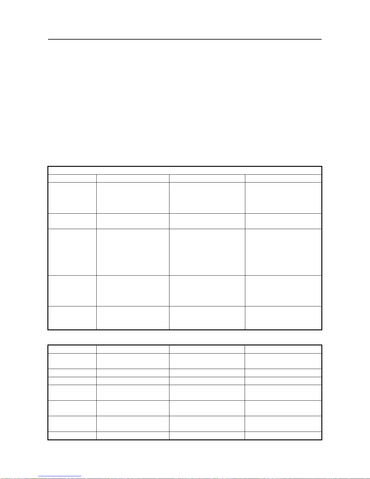
GENERAL SPECIFICATIONS
2-1
SPECIFICATIONS
1. How to use conversion table of unit
(1)How to use conversion table
All the specified documents in this manual are taken SI and Metric as unit. With the following conversion
table, metric unit could be conversed into imperial unit.
Sample:
METRIC MULTIPLY IMPERIAL
mm 0.03937 =in
2mm
× 0.03937 =0.08in
Conversion table
Conversion between metric and imperial
Know unit Multiply Product
Torque
m·kg
m·kg
cm·kg
cm·kg
7.233
86.794
0.0723
0.8679
ft·lb
in·lb
ft·lb
in·lb
Weight
kg
g
2.205
0.03527
lb
oz
Length
km/hr
km
m
m
cm
mm
0.6214
0.6214
3.281
1.094
0.3937
0.03937
mph
mi
ft
yd
in
in
Volume/capacity
cc(cm3)
cc(cm3)
lit(liter)
lit(liter)
0.03527
0.06102
0.8799
0.2199
oz(IMP liq.)
cu·in
qt(IMP liq.)
gal(IMP liq.)
Others
kg/mm
kg/cm
2
Centigrade
55.997
14.2234
9/5(℃)+32
Ib/in
psi(lb/in2)
Fahrenheit(°F)
(2)1
Unit Read Definition Measurement
mm
cm
Millimetre
Centimetre
1 mm=10-3Meter
1 cm =10-2Meter
Length
Length
kg Kilogram 1 kg =103Gram Weight
N Newton 1N=1 kg×meter/second² Force
N.m
kgf.m
Newton meter
Meter Kilogram
1 Nm=1Newton×1meter
1 kgf.m =1Meter×1kgf
Torque
Torque
Pa
N/mm
Pascal
Newton per millimeter
1 Pa=1Newton/1meter2
1 N/mm =1Newton/ millimeter
Pressure
Rigid of spring
L
cm3
Litre
Cubic centimeter
—
Volume of capacity
r/min Revolutions per minute — Rotational speed
Page 75
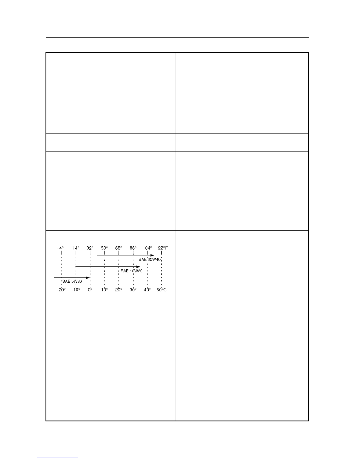
GENERAL SPECIFICATIONS
2-2
2. General specifications
Item Standard
Dimensions :
Overall length
Overall width
Overall height
Seat height
Wheelbase
Minimum ground clearance
Minimum turning radius
3,010 mm(118.5 in)
1,460 mm(57.5 in)
1,940 mm(77.2 in)
818 mm(32.2 in)
1,890 mm(72.4 in)
280 mm(11.0 in)
3,900 mm(154 in)
Basic weight :
With oil and full fuel tank
543 kg (1,197 lb)
Engine :
Engine type
Cylinder arrangement
Displacement
Bore×stroke
Compression ratio
Starting system
Lubrication system
Liquid cooled 4-stroke, Water cool
Forward-inclined single cylinder
686cm
3
100×84.0mm(3.94×3.31in)
9.1:1
Electric starter
Wet sump
Engine oil :
Final gear oil
Differential gear oil
Engine oil
Periodic oil change
With oil filter replacement
Total amount
Final gear case oil
Periodic oil change
Total amount
Differential gear case oil
Periodic oil change
Total amount
API service SG type or higher, JASO standard MA
SAE80 API GL-4 Hypoid gear oil
SAE80 API GL-5 Hypoid gear oil
2.10 L(1.85 Imp qt, 2.22 US qt)
1.90 L(1.67lmp qt, 2.01 US qt)
2.40 L(2.11 Imp qt, 2.54 US qt)
0.25 L(0.22 Imp qt, 0.26 US qt)
0.28 L(0.25 Imp qt, 0.30 US qt)
0.32 L(0.28 Imp qt, 0.34 US qt)
0.33 L(0.29 Imp qt, 0.35 US qt)
Page 76
GENERAL SPECIFICATIONS
2-3
Item Standard
Air filter Wet type element
Fuel
Type
Fuel tank capacity
Unleaded gasoline only
30.0L(6.60 lmp gal, 7.93 US gal)
Carburetor
Type/quantity
PD42J-A / 1
Spark plug
Type/manufacturer
Spark plug gap
DPR8EA / 1(NGK)
0.8-0.9 mm(0.031-0.035 in)
Clutch type Wet ,centrifugal automatic
Transmission
Primary reduction system
Secondary reduction system
Secondary reduction ratio
Transmission type
Operation
Single speed automatic
Sub transmission ratio Low
High
Reverse gear
V-belt
Shaft drive
41/21×24/18×33/9(9.544)
V-belt automatic
Right hand operation
2.37 ~ 0.91 : 1
35/17(2.058)
28/19(1.473)
25/14(1.471)
Chassis
Frame type
Camber angle
Trail
Toe-in
Steel tube frame
5°
26.0mm(1.02 in)
0 ~ 10 mm (0.00 ~ 0.39 in)
Tire
Type
Size Front
Rear
Pressure of front wheel
Pressure of rear wheel
Tubeless
25×8-12 NHS
25×10-12 NHS
70kpa
70kpa
Brake
Ⅰ: Front brake Type
Operation
Rear brake Type
Operation
Ⅱ: Front brake Type
Operation
Rear brake Type
Operation
Dual disc brake
Foot operation
Single disc brake
Foot operation
Dual disc brake
Foot operation
Dual disc brake
Foot operation
Page 77

GENERAL SPECIFICATIONS
2-4
Item Standard
Suspension
Front suspension
Rear suspension
Shock absorber
Front shock absorber
Rear shock absorber
Wheel travel
Front wheel travel
Rear wheel travel
Double wishbone
Double wishbone
Coil spring/oil damper
Coil spring/oil damper
185 mm (7.3 in)
185 mm (7.3 in)
Electrical
Ignition system
Generator system
Battery type
Battery capacity
C.D.I.
A.C. magneto
U1L-11
12 V, 32.0Ah
Headlight type
Bulb wattage×quantity
Headlight
Tail/brake light
Neutral
Reverse
Coolant temperature
Parking brake
Four-wheel drive
Differential gear lock
Krypton bulb
12V30.3W/30.0W × 2
12V5.0W/21.0W × 2
20 MA 0.06 W×1 LED
20 MA 0.06 W×1 LED
20MA 0.06 W×1 LED
20MA 0.06 W×1 LED
20MA 0.06 W×1 LED
20MA 0.06 W×1 LED
Page 78
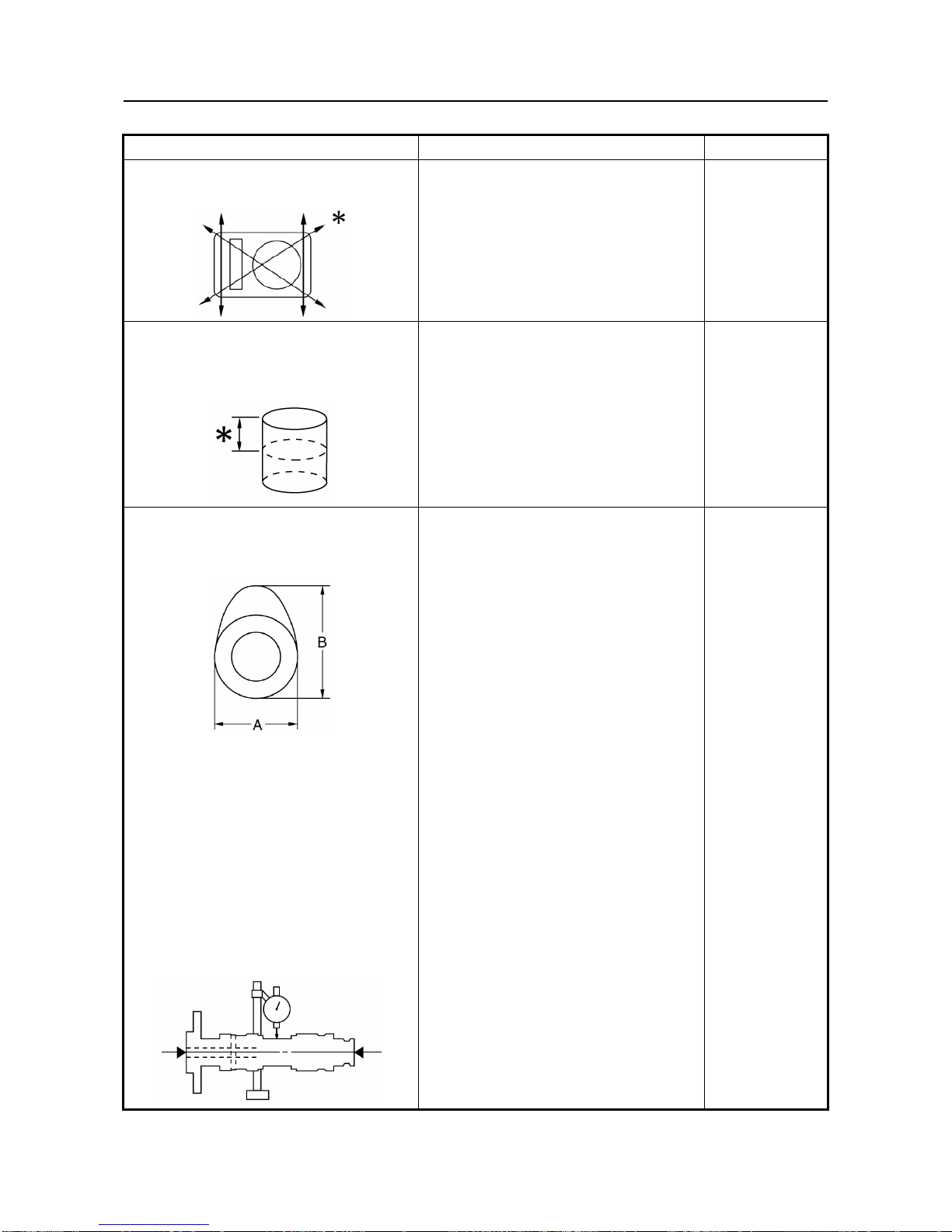
GENERAL SPECIFICATIONS
2-5
ENGINE SPECIFICATIONS
Item Standard Limit
Cylinder head
Warp limit
*
----
0.03 mm
(0.0012 in)
Cylinder
Bore size
Measuring point
*
100.005 ~ 100.055 mm
(3.9372 ~ 3.9392 in)
50 mm (1.97 in)
100.10 mm
(3.9410 in)
----
Camshaft
Drive method
Cam dimensions
Chain drive (Left)
----
Intake “A”
“B”
Exhaust “A”
“B”
30.06 ~ 30.16 mm
(1.1835 ~ 1.1874 in)
35.69 ~ 35.79 mm
(1.4051 ~ 1.4091 in)
30.11 ~ 30.21 mm
(1.1854 ~ 1.1894 in)
36.50 ~ 36.60 mm
(1.4370 ~ 1.4409 in)
(1.1795 in)
29.96 mm
35.59 mm
(1.4012 in)
30.01 mm
(1.1815 in)
36.40 mm
(1.4331 in)
Camshaft runout limit
---
0.03 mm
(0.0012 in)
Page 79
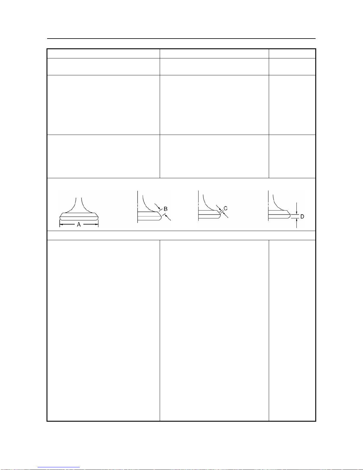
GENERAL SPECIFICATIONS
2-6
Item Standard Limit
Cam chain
Cam chain adjustment method
Automatic
Rocker arm/rocker arm shaft
Rocker arm inside diameter
Shaft outside diameter
Arm-to-shaft clearance
12.000 ~ 12.018 mm
(0.4724 ~ 0.4731 in)
11.976 ~ 11.991 mm
(0.4715 ~ 0.4721 in)
0.009 ~ 0.042 mm
(0.0004 ~ 0.0017 in)
----
----
Valve, valve seat, valve guide
Valve clearance (cold) IN
EX
0.10 ~ 0.15 mm
(0.0039 ~ 0.0059 in)
0.15 ~ 0.20 mm
(0.0059 ~ 0.0079 in)
----
----
Valve dimensions
head diameter face width seat width margin thickness
“A” head diameter IN
EX
“B” face width
IN
EX
“C” seat width
IN
EX
“D” margin thickness
IN
EX
Stem outside diameter IN
EX
Guide inside diameter
IN
EX
29.9 ~ 30.1 mm
(1.1772 ~ 1.1850 in)
31.9 ~ 32.1 mm
(1.2559 ~ 1.2638 in)
2.25 mm (0.0900 in)
2.26 mm
(0.0890 in)
0.9 ~ 1.1 mm
(0.0354 ~ 0.0433 in)
0.9 ~ 1.1 mm
(0.0354 ~ 0.0433 in)
0.85 ~ 1.15 mm
(0.0335 ~ 0.0453 in)
0.85 ~ 1.15 mm
(0.0335 ~ 0.0453 in)
5.975 ~ 5.990 mm
(0.2352 ~ 0.2358 in)
5.960 ~ 5.975 mm
(0.2346 ~ 0.2352 in)
6.000 ~ 6.012 mm
(0.2362 ~ 0.2367 in)
6.000 ~ 6.012 mm
(0.2362 ~ 0.2367 in)
----
----
----
----
1.6 mm
(0.0630 in)
1.6 mm
(0.0630 in)
----
----
5.945 mm
(0.2341 in)
5.930 mm
(0.2335 in)
6.050 mm
(0.2559 in)
6.050 mm
(0.2559 in)
Page 80
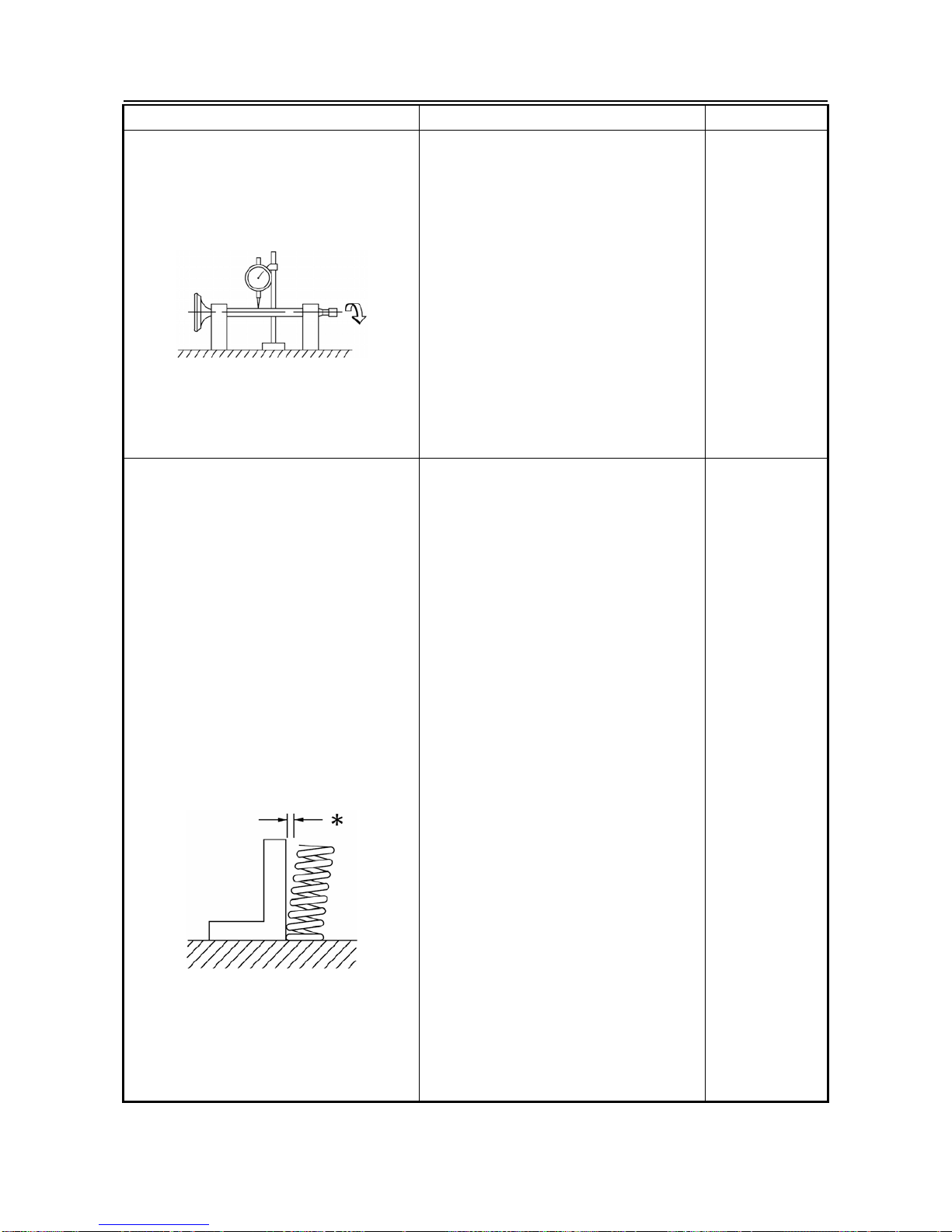
GENERAL SPECIFICATIONS
2-7
Item Standard Limit
Stem-to-guide clearance IN
EX
Stem runout limit
Valve seat width
IN
EX
0.010 ~ 0.037 mm
(0.0004 ~ 0.0015 in)
0.025 ~ 0.052 mm
(0.0010 ~ 0.0020 in)
----
0.9 ~ 1.1 mm
(0.0354 ~ 0.0433 in)
0.9 ~ 1.1 mm
(0.0354 ~ 0.0433 in)
0.08 mm
(0.0031 in)
0.10 mm
(0.0039 in)
0.01 mm
(0.0004 in)
----
----
Valve spring
Inner spring
Free length IN
EX
Set length (valve closed) IN
EX
Compressed pressure
(installed) IN
EX
Tilt limit
* IN
EX
Direction of winding
(top view)
IN
EX
32.63 mm (1.28 in)
36.46 mm(1.44 in)
27.5 mm (1.08 in)
31.0 mm(1.22 in)
100.0 ~ 115.7 N
(10.20 ~ 11.80 kg, 22.49 ~ 26.01 lb)
120.6 ~ 138.3 N
(12.30 ~ 14.10 kg, 27.12 ~ 31.09 lb)
----
----
Clockwise
Clockwise
31.0 mm
(1.22 in)
34.6 mm
(1.36 in)
----
----
----
2.5°/1.4 mm
(2.5°/0.055 in)
2.5°/1.6 mm
(2.5°/0.063 in)
----
----
Page 81
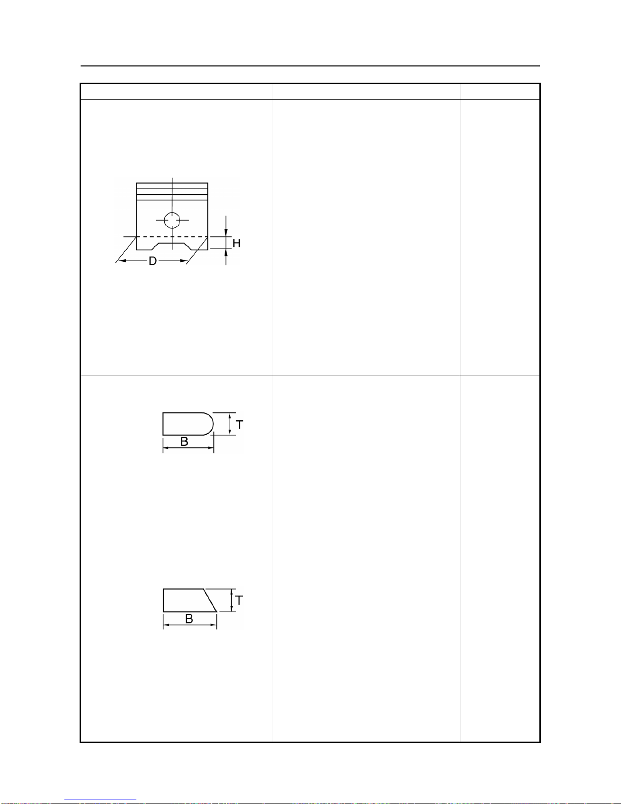
GENERAL SPECIFICATIONS
2-8
Item Standard Limit
Piston
Piston to cylinder clearance
Piston size “D”
Measuring point “H”
Piston off-set
Off-set direction
Piston pin bore inside diameter
Piston pin outside diameter
0.050 ~ 0.070 mm
(0.0020 ~ 0.0028 in)
99.945 ~ 99.995 mm
(3.9348 ~ 3.9368 in)
2.5 mm (0.10 in)
1.0 mm(0.0394 in)
Intake side
22.004 ~ 22.015 mm
(0.8663 ~ 0.8667 in)
21.991 ~ 22.000 mm
(0.8658 ~ 0.8661 in)
0.15 mm
(0.0059 in)
----
----
----
----
22.045 mm
(0.8679 in)
21.971 mm
(0.8650 in)
Piston rings
Top ring
Type
Dimensions (B×T)
End gap (installed)
Side clearance (installed)
2nd ring
Type
Dimensions (B ×T)
End gap (installed)
Side clearance
Barrel
1.2 ×3.8 mm
(0.0472 ×0.1496 in)
0.30 ~ 0.45 mm
(0.0118 ~ 0.0177 in)
0.04 ~ 0.08 mm
(0.0016 ~ 0.0031 in)
Taper
1.2×4.0 mm
(0.0472 0.1575 in)
0.30 ~ 0.45 mm
(0.0118 ~ 0.0177 in)
0.03 ~ 0.07 mm
(0.0012 ~ 0.0028 in)
----
----
0.70 mm
(0.0276 in)
0.13 mm
(0.0051 in)
----
----
0.80 mm
(0.0315 in)
0.13 mm
(0.0051 in)
Page 82
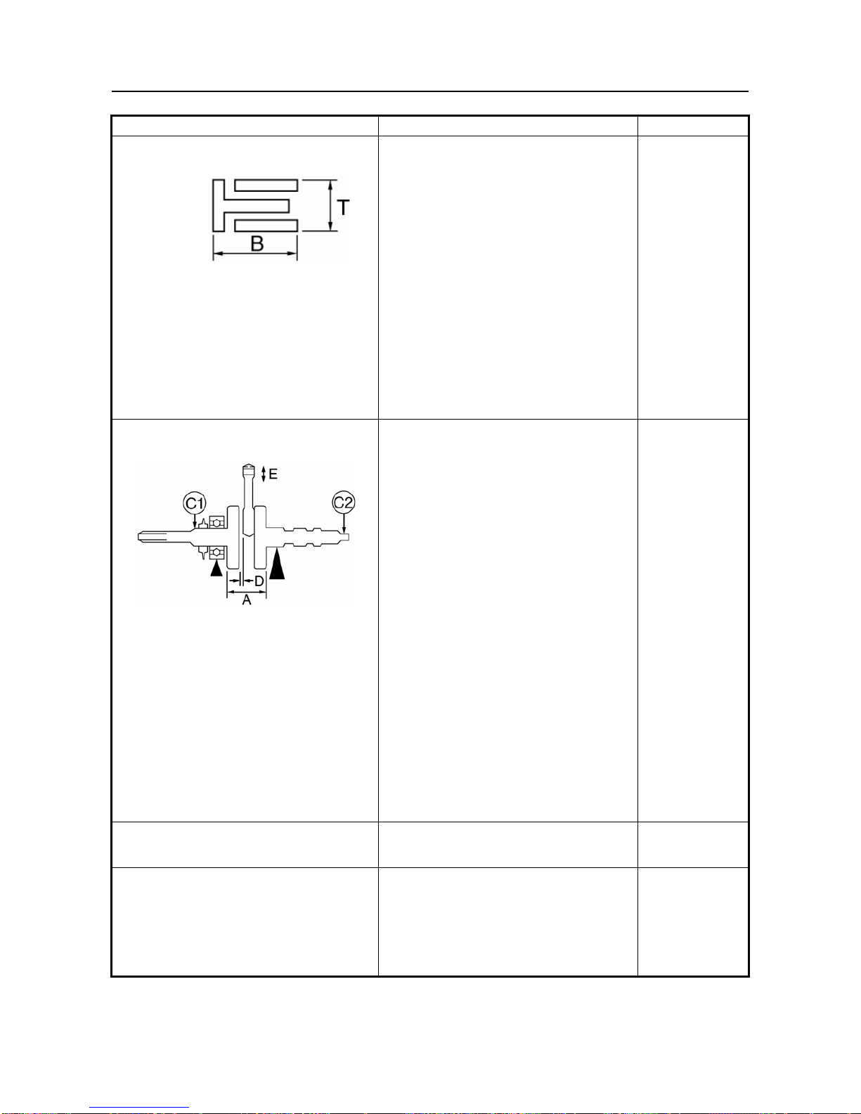
GENERAL SPECIFICATIONS
2-9
Item Standard Limit
Oil ring
Dimensions (B×T)
End gap (installed)
Side clearance
2.5×3.4 mm
(0.0984×0.1339 in)
0.20 ~ 0.70 mm
(0.0079 ~ 0.0276 in)
0.06 ~ 0.15 mm
(0.0024 ~ 0.0059 in)
----
----
----
Crankshaft
Crank width “A”
Runout limit C1
C2
Big end side clearance “D”
Big end radial clearance “E”
74.95 ~ 75.00 mm
(2.9508 ~ 2.9528 in)
----
----
0.35 ~ 0.65 mm
(0.0138 ~ 0.0256 in)
0.010 ~ 0.025 mm
(0.0004 ~ 0.0010 in)
----
0.03 mm
(0.0012 in)
0.03 mm
(0.0012 in)
1.0 mm
(0.0394 in)
----
Balancer
Balancer drive method
Gear
----
Automatic centrifugal clutch
Clutch shoe thickness
Clutch-in revolution
Clutch-stall revolution
1.5 mm
(0.06 in)
1,900 ~ 2,300 r/min
3,350 ~ 3,850 r/min
1.0 mm
(0.04 in)
----
----
Page 83

GENERAL SPECIFICATIONS
2-10
Item Standard Limit
Transmission
Main axle deflection limit
Drive axle deflection limit
----
----
0.06 mm
(0.0024 in)
0.06 mm
(0.0024 in)
Shifter
Shifter type
Shift drum and guide bar
----
Air filter oil grade Engine oil ----
Carburetor
Mark
Main jet
Main air jet
Pilot jet
Needle jet
Float height
Fuel level
Float needle
Engine idle speed
KINZO
1.1
13 mm (0.51 in)
4.0 ~ 5.0 mm (0.16 ~ 0.20 in)
3mm
1,400~ 1,500r/min
----
----
----
----
----
----
----
----
Oil pump
Oil filter type
Oil pump type
Tip clearance
Side clearance
Body clearance
Bypass valve setting pressure
Oil pressure (hot)
Pressure check location
Foam
Trochoid
0.15 mm
(0.0059 in)
0.03 ~ 0.10 mm
(0.0012 ~ 0.0039 in)
0.09 ~ 0.17 mm
(0.0035 ~ 0.0067 in)
441.0 ~ 637.0 kPa
(4.41 ~ 6.37 kg/cm2, 62.7 ~ 90.6 psi)
65 kPa (0.65 kg/cm2, 9.2 psi)
at 1,500 r/min
Cylinder head
----
----
0.23 mm
(0.0091 in)
0.17 mm
(0.0067 in)
0.24 mm
(0.0094 in)
----
----
----
Water pump
Type
Reduction ratio
Single-suction centrifugal pump
32/31 (1.032)
----
----
Shaft drive
Middle gear backlash
Final gear backlash
Differential gear backlash
0.1 ~ 0.3 mm (0.004 ~ 0.012 in)
0.1 ~ 0.3 mm (0.004 ~ 0.012 in)
0.05 ~ 0.25 mm(0.002 ~ 0.010 in)
----
----
----
Cooling system
Radiator core
Width
380 mm (14.96 in)
----
Page 84

GENERAL SPECIFICATIONS
2-11
Height
Thickness
Radiator cap opening pressure
Radiator capacity
(including all routes)
Coolant reservoir
Capacity
From low to full level
238 mm (9.37 in)
24 mm (0.94 in)
107.9 ~ 137.3 kPa
(1.079~1.373 kg/cm2, 15.35~19.53 psi)
2.5 L (2.20 Imp qt, 2.64 US qt)
0.35 L (0.31 Imp qt, 0.37 US qt)
0.20 L (0.15 Imp qt, 0.21 US qt)
----
----
----
----
----
----
Page 85

GENERAL SPECIFICATIONS
2-12
CHASSIS SPECIFICATIONS
Item Standard Limit
Steering system
Type
Rack and pinion
----
Front suspension
Shock absorber travel
Spring free length
Spring fitting length
Spring rate
Stroke
108 mm (4.25 in)
313 mm (12.32 in)
247.9 mm (9.76 in)
19.4 N/mm(1.94 kg/mm, 108.6 lb/in)
0 ~ 108 mm (0 ~ 4.25 in)
----
----
----
----
Rear suspension
Shock absorber travel
Spring free length
Spring fitting length
Spring rate
Stroke
81 mm (3.19 in)
328 mm (12.91 in)
273.2 mm (10.76 in)
44.1 N/mm (4.41 kg/mm, 246.95 lb/in)
117.7N/mm (11.77kg/mm, 659.08 lb/in)
0 ~ 60 mm (0 ~ 2.36 in)
60 ~ 81 mm (2.36 ~ 3.15 in)
----
----
----
----
----
----
----
Front wheel
Type
Rim size
Rim material
Rim runout limit radial
lateral
Panel wheel
12 ×6.0 AT
Steel
----
----
----
----
----
2.0 mm
(0.08 in)
2.0 mm
(0.08 in)
Rear wheel
Type
Rim size
Rim material
Rim runout limit radial
lateral
Panel wheel
12×7.5 AT
Steel
----
----
----
----
----
2.0 mm
(0.08 in)
2.0 mm
(0.08 in)
Brake lever and brake pedal
Accelerator pedal free play
Brake pedal free play
Parking brake cable free play
0 mm (0.0 in)
0 mm (0.0 in)
2 ~ 3 mm (0.079 ~ 0.118 in)
----
----
----
Page 86

GENERAL SPECIFICATIONS
2-13
Item
Standard Limit
Front disc brake
Type
Disc outside diameter × thickness
Pad thickness inner
Pad thickness outer
Master cylinder inside diameter
Caliper cylinder inside diameter
Brake fluid type
Dual
200 × 3.5 mm (7.87 × 0.14 in)
5.2 mm
(0.20 in)
5.2 mm
(0.20 in)
17.4 mm (0.69 in)
27.0 mm (1.06 in)
DOT 4
----
----
1.5 mm
(0.06 in)
1.5 mm
(0.06 in)
----
----
----
Rear disc brake
Type
Disc outside diameter × thickness
Pad thickness inner
Pad thicknessmm
outer
Master cylinder inside diameter
Caliper cylinder inside diameter
Brake fluid type
Single or Dual
165.0 × 5.0 mm (6.50 × 0.20 in)
5.6 mm
(0.22 in)
5.6 mm
(0.22 in)
17.4 mm (0.69 in)
32.0 mm (1.26 in)
DOT 4
----
----
1.5 mm
(0.06 in)
1.5
(0.06 in)
----
----
----
Page 87
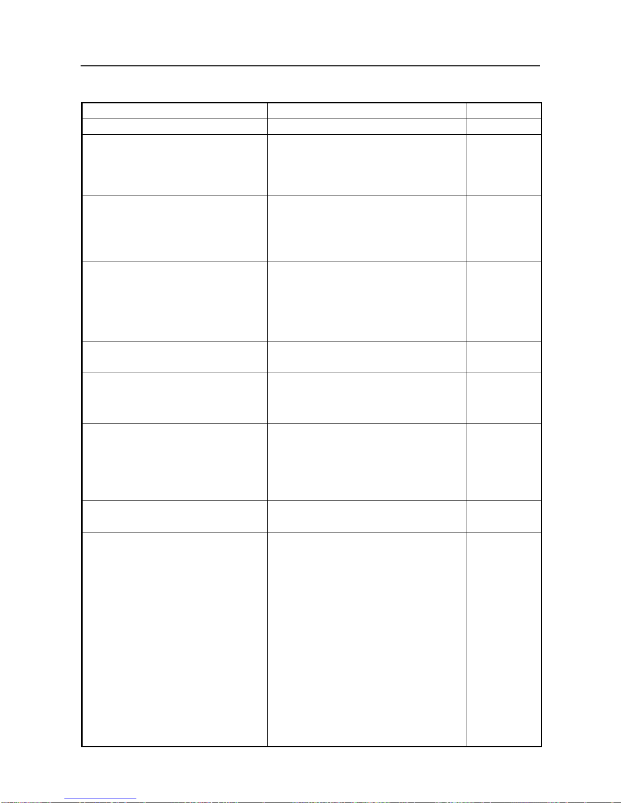
GENERAL SPECIFICATIONS
2-14
ELECTRICAL SPECIFICATIONS
Item Standard Limit
Voltage 12 V ---Ignition system
Ignition timing (BTDC)
(BTDC)
Advancer type
12°/ 1,500 r/min
Digital type
----
----
C.D.I.
Pickup coil resistance/color
Rotor rotation direction sensing coil
resistance/color
459 ~ 561 Ωat 20 °C (68 °F)/
White/Red – White/Green
0.063 ~ 0.077 Ωat 20 °C (68 °F)/
----
----
Ignition coi
Minimum spark gap
Primary winding resistance
Secondary winding resistance
6 mm (0.24 in)
0.18 ~ 0.28 Ωat 20 °C (68 °F)
6.32 ~ 9.48 kΩat 20 °C (68 °F)
----
----
----
----
Spark plug cap
Resistance
10 kΩ
----
Charging system
Nominal output
Charging coil resistance/color
14 V 23 A at 5,000 r/min
0.32 ~ 0.43Ωat 20 ℃ (68 °F)/White – White
----
----
Rectifier/regulator
Regulator type
No load regulated voltage (DC)
Capacity
Withstand voltage
Semi conductor-short circuit
14.1 ~ 14.9 V
18 A
200 V
----
----
----
----
Battery
Specific gravity
1.32
----
Circuit breaker
Type
Main fuse
Lighting system fuse
Ignition fuse
Auxiliary DC jack fuse
Four-wheel drive fuse
Signaling system fuse
Carburetor heater fuse
Backup fuse (odometer)
Reserve
Reserve
Reserve
Reserve
Fuse
30A×1
15 A×1
10 A×1
10 A×1
3 A×1
10 A×1
10 A×1
10 A×1
30 A×1
15 A×1
10 A×1
3 A×1
----
----
----
----
----
----
----
----
----
----
----
----
Page 88
GENERAL SPECIFICATIONS
2-15
Item Standard Limit
Electric starter system
Type
Starter motor
Output
Armature coil resistance
Brush overall length
Spring force
Commutator diameter
Mica undercut
Starter relay
Amperage rating
Coil winding resistance
Constant mesh type
0.8 kW
0.025 ~ 0.035 Ωat 20 °C (68 °F)
12.5 mm (0.49 in)
7.65 ~ 10.01 N
(780 ~ 1,021 g, 27.5 ~ 36.0 oz)
28 mm (1.10 in)
0.7 mm (0.03 in)
180 A
4.18 ~ 4.62 at 20 °C (68 °F)
----
----
----
----
5 mm(0.20 in)
----
27 mm(1.06 in)
----
-----
Radiator fan
Running rpm
2,950 r/min
----
Page 89
GENERAL SPECIFICATIONS
2-16
TIGHTENING TORQUES
ENGINE TIGHTENING TORQUES
Tightening torque
Part to be tightened Part name
Thread
size
Q’ty
Nm m · kg ft · lb
Remarks
Cylinder head
Spark plug
Cylinder head (exhaust pipe)
Cylinder head cover
Tappet cover (exhaust)
Tappet cover (intake)
Oil gallery bolt
Camshaft end cap
Cylinder
Balancer driven gear
Timing chain tensioner
Timing chain tensioner cap
Timing chain guide (intake side)
Camshaft sprocket
Rocker arm shaft stopper
Valve adjusting locknut
Engine oil drain bolt
Oil filter cartridge union bolt
Oil filter cartridge
Oil pipe assembly
Oil delivery pipe 1
Oil delivery pipe 2
Oil delivery pipe 3
Oil delivery pipe 2 and oil delivery
pipe 3
Relief valve assembly plate
Oil strainer
Oil pump assembly
Oil cooler inlet pipe 1/oil cooler
outlet pipe 1
Oil cooler inlet pipe 1/oil cooler outlet
pipe 1 clamp
Oil cooler inlet pipe 2/oil cooler
outlet pipe 2 clamp
Intake manifold
Carburetor joint (intake manifold)
Intake manifold screw clamp
Bolt
Bolt
—
Stud bolt
Bolt
—
Bolt
—
Bolt
Bolt
Bolt
Nut
Bolt
Bolt
Bolt
Bolt
Bolt
—
—
—
—
Bolt
Union Bolt
Union Bolt
Union Bolt
Union bolt
Bolt
Bolt
Bolt
Bolt
Bolt
Bolt
Bolt
—
—
M6
M9
M12
M8
M6
M32
M6
M6
M6
M6
M10
M18
M6
M6
M6
M7
M6
M6
M14
M20
M20
M6
M8
M14
M10
M14
M6
M6
M6
M6
M6
M6
M6
M5
M5
1
6
1
4
17
2
4
1
1
2
4
1
2
1
2
2
2
5
1
1
1
4
2
1
1
1
2
1
3
2
1
2
4
1
1
10
38
18
15
10
12
10
7
10
10
42
110
10
7
8
20
10
14
30
63
17
7
18
35
20
35
10
10
10
7
7
7
10
3
3
1.0
3.8
1.8
1.5
1.0
1.2
1.0
0.7
1.0
1.0
4.2
11.0
1.0
0.7
0.8
2.0
1.0
1.4
3.0
6.3
1.7
0.7
1.8
3.5
2.0
3.5
1.0
1.0
1.0
0.7
0.7
0.7
1.0
0.3
0.3
7.2
27
13
11
7.2
8.7
7.2
5.1
7.2
7.2
30
80
7.2
5.1
5.8
14
7.2
10
22
4.6
12
5.1
13
25
14
25
7.2
7.2
7.2
5.1
5.1
5.1
7.2
2.1
2.1
Page 90
GENERAL SPECIFICATIONS
2-17
Tightening torque
Part to be tightened Part name
Thread
size
Q’ty
Nm m · kg ft · lb
Remarks
Bolt M8 3 26 2.6 19
Bolt M6 14 10 1.0 7.2
Bolt M6 1 10 1.0 7.2
Crankcase
Bearing housing (clutch housing
assembly)
Bolt M6 1 10 1.0 7.2
Air duct assembly 1 bracket Bolt M6 2 14 1.4 10
Oil seal (engine cooling fan pulley)
Retainer
Bolt M5 2 7 0.7 5.1
Drive belt case Bolt M6 9 10 1.0 7.2
Drive belt cover Bolt M6 14 10 1.0 7.2
Engine cooling fan Bolt M6 2 7 0.7 5.1
Air shroud 1 and air shroud 2
Bolt M6 4 10 1.0 7.2
Air shroud 2 and A.C. magneto cover Bolt M6 4 10 1.0 7.2
Engine cooling fan pulley Bolt M10 1 55 5.5 40
Engine cooling fan air duct assembly Bolt M6 1 7 0.7 5.1
Stator assembly Screw M6 3 7 0.7 5.1
Pickup coil Bolt M5 2 7 0.7 5.1
Stator lead holder Bolt M6 2 10 1.0 7.2
A.C. magneto cover Bolt M6 12 10 1.0 7.2
Starter clutch Bolt M8 3 30 3.0 22
Clutch carrier assembly Nut M22 1 160 16.0 115 Stake
Clutch housing assembly Bolt M6 9 10 1.0 7.2
Bearing retainer (middle drive shaft)
Screw M8 4 29 2.9 21
Middle drive pinion gear Nut M22 1 145 14.5 105 Stake
Middle drive shaft bearing housing Bolt M8 4 32 3.2 23
Middle driven pinion gear bearing
Retainer
Nut M60 1 110 11.0 80
Left-hand
threads
Universal joint yoke and middle
driven pinion gear
Nut M16 1 150 15.0 110
Middle driven pinion gear bearing
Housing
Bolt M8 4 25 2.5 18
Drive shaft coupling and middle
driven shaft
Nut M14 1 97 9.7 70
Middle driven shaft bearing retainer
Nut M55 1 80 8.0 58
Left-hand
threads
Primary sheave assembly Nut M16 1 120 12.0 85
Primary pulley sheave cap Screw M4 8 3 0.3 2.2
Secondary sheave assembly Nut M16 1 100 10.0 72
Secondary sheave spring retainer Nut M36 1 90 9.0 65
Shift lever cover Bolt M6 4 10 1.0 7.2
Shift lever 2 assembly Bolt M6 1 14 1.4 10
Shift drum stopper Bolt M14 1 18 1.8 13
Shift arm Bolt M6 1 14 1.4 10
Page 91

GENERAL SPECIFICATIONS
2-18
Shift rod locknut (select lever unit)
— M8 1 15 1.5 11
Left-hand
threads
Q’ty
15 1.5 11
Part to be tightened Part name
Thread
size
Nm
m.kg ft · lb Nm
Remarks
Shift rod locknut (shift arm side) — M8 1 15 1.5 11
Select lever unit Bolt M8 3 15 1.5 11
Plug (right crankcase) — M14 1 18 1.8 13
Water pump assembly Bolt M6 2 10 1.0 7.2
Water pump housing cover Bolt M6 2 12 1.2 8.7
Coolant drain bolt — M6 1 10 1.0 7.2
Coolant inlet joint Bolt M6 2 10 1.0 7.2
Coolant outlet joint Bolt M6 2 10 1.0 7.2
Air bleed bolt (coolant outlet joint) — M6 1 9 0.9 6.5
Coolant reservoir Bolt M6 2 7 0.7 5.1
Radiator bracket and frame Bolt M6 4 7 0.7 5.1
Fuel pump Bolt M6 2 7 0.7 5.1
Fuel tank Bolt M8 2 30 3.0 22
Muffler stay Bolt M6 2 11 1.1 8.0
Muffler and exhaust pipe Bolt M8 1 20 2.0 14
Muffler bracket and muffler Bolt M8 1 20 2.0 14
Muffler bracket and frame Bolt M8 2 20 2.0 14
Muffler damper and muffler Bolt M6 1 10 1.0 7.2
Muffler damper and frame Bolt M6 1 10 1.0 7.2
Exhaust pipe Nut M8 4 14 1.4 10
Air duct assembly 1 Bolt M6 2 7 0.7 5.1
Air duct assembly 2 and left protector Bolt M6 1 7 0.7 5.1
Air duct assembly 2 and frame Bolt M6 1 7 0.7 5.1
Gear position switch Bolt M5 2 7 0.7 5.1
Thermo switch 1 (cylinder head)
— 1/8 1 8 0.8 5.8
Thermo switch 3 (radiator)
— M18 1 28 2.8 20
Reverse switch — M10 1 20 2.0 14
Engine ground lead Bolt M6 1 10 1.0 7.2
Starter motor and engine Bolt M6 2 10 1.0 7.2
Page 92

GENERAL SPECIFICATIONS
2-19
CHASSIS TIGHTENING TORQUES
Tightening torque
Part to be tightened
Thread
size
Nm m · kg ft · lb
Remarks
Rubber connecting bracket 1(or 2) and frame M10 52 5.2 37
Engine and Rubber connecting bracket 2 (front) M10 52 5.2 37
M6 10 1.0 7.2
Engine and Rubber connecting bracket 1 (rear) M8 33 3.3 24
M6 10 1.0 7.2
Rear upper arm and frame M10 45 4.5 32
Rear lower arm and frame M10 45 4.5 32
Rear knuckle and rear upper arm M10 45 4.5 32
Rear knuckle and rear lower arm M10 45 4.5 32
Rear shock absorber and frame M10 45 4.5 32
Rear shock absorber and rear lower arm M10 45 4.5 32
Rear Balancing pole and frame M8 32 3.2 23
ball head of Rear Balancing pole and Rear Balancing
pole
M10 56 5.6 40
ball head of Rear Balancing pole and rear lower arm M10 56 5.6 40
Differential gear case and frame M10 55 5.5 40
Differential gear case filler plug M14 23 2.3 17
Differential gear case drain plug M10 10 1.0 7.2
Universal joint yoke and drive pinion gear M14 62 6.2 45
Differential motor and differential gear case cover M8 13 1.3 9.4
Differential gear case cover and differential gear case M8 25 2.5 18
Rear driving axle gear case and frame M10 70 7.0 51
Rear driving axle gear case filler plug M20 23 2.3 17
Rear driving axle gear case drain plug M10 20 2.0 14
Ring gear bearing housing and final drive gear case M8 23 2.3 17
M10 40 4.0 29
Ring gear stopper nut M8 16 1.6 11
Bearing retainer and final gear pinion gear bearing housing
M65 170 17.0 125
Left-hand
threads
Coupling gear and final drive pinion gear
M12 80 8.0 58
Front upper arm and frame M10 45 4.5 32
Front lower arm and frame M10 45 4.5 32
Front shock absorber and frame M10 45 4.5 32
Front shock absorber and front upper arm M10 45 4.5 32
Steering shaft assembly and steering Cross gimbal M8 22 2.2 16
Steering assembly and steering Cross gimbal M8 22 2.2 16
Steering assembly and frame M10 48 4.8 35
Steering shaft assembly and frame M8 21 2.1 15
Steering wheel and steering shaft assembly M12 35 3.5 25
Steering knuckle and front upper arm M12 30 3.0 22
Steering knuckle and front lower arm M12 30 3.0 22
Tie-rod locknut M12 40 4.0 29
Steering knuckle and tie-rod M12 39 3.9 28
Front lower arm protector board and front lower arm M6 7 0.7 5.1
Page 93

GENERAL SPECIFICATIONS
2-20
Seat belt and frame M10 59 5.9 43
Seat belt and ceiling (enclosure) 7/16 59 5.9 43
Front wheel and front wheel hu M10 55 5.5 40
Front wheel hub and constant velocity joint of half shaft M20 260 26.0 190 Stake
Steering knuckle and brake disc guard M6 7 0.7 5.1
Front brake caliper and front wheel steering knuckle M10 48 4.8 35
Front brake hose union bolt M10 27 2.7 19
Front brake hose holder and steering knuckle M6 7 0.7 5.1
Front brake hose holder and front upper arm M6 7 0.7 5.1
Front brake hose holder and frame M6 7 0.7 5.1
Front brake pad holding bolt M8 18 1.8 13
Front brake disc and front wheel hub M8 30 3.0 22
Front brake caliper bleed screw M6 6 0.6 4.3
Rear wheel and rear wheel hub M10 55 5.5 40
Rear wheel hub and constant velocity joint of half shaft M20 260 26.0 190 Stake
Rear brake hose and frame M6 7 0.7 5.1
Brake pipe and brake master cylinder M10 19 1.9 13
Pedal holder assembly and frame M8 16 1.6 11
Brake master cylinder and pedal holder assembly M8 16 1.6 11
Secondary brake master cylinder kit stopper bolt M6 9 0.9 6.5
Brake rod locknut M8 17 1.7 12
Rear brake disc and brake disc Install seat M6 10 1.0 7.2
Rear brake pad holding bolt M8 17 1.7 12
Rear brake caliper and Install seat M10 40 4.0 29
Rear brake hose union bolt M10 27 2.7 19
Parking brake case and rear brake caliper M8 22 2.2 16
Parking brake lever assembly and frame M6 7 0.7 5.1
Rear brake caliper bleed screw M6 5 0.5 3.6
Cargo bed release leve M6 11 1.1 8.0
M8 26 2.6 19
Rubber pad and cargo bed assembly M8 16 1.6 11
Hinge cover and cargo bed assembly — 7 0.7 5.1
Cargo bed plastic panel and cargo bed assembly M6 7 0.7 5.1
Rear mud guard and cargo bed assembly M6 7 0.7 5.1
Front bumper protector board and front bumper M6 7 0.7 5.1
Front bumper and frame M10 32 3.2 23
M12 59 5.9 43
Upper instrument panel and frame M6 7 0.7 5.1
ceiling side frame (enclosure) and frame M10 64 6.4 46
Support frame (enclosure) and frame M10 64 6.4 46
Support frame (enclosure) and side frame (enclosure) M10 64 6.4 46
Top frame (enclosure) and side frame (enclosure) M10 64 6.4 46
Seat support and frame M8 16 1.6 11
Footrest plate and frame M6 7 0.7 5.1
Page 94
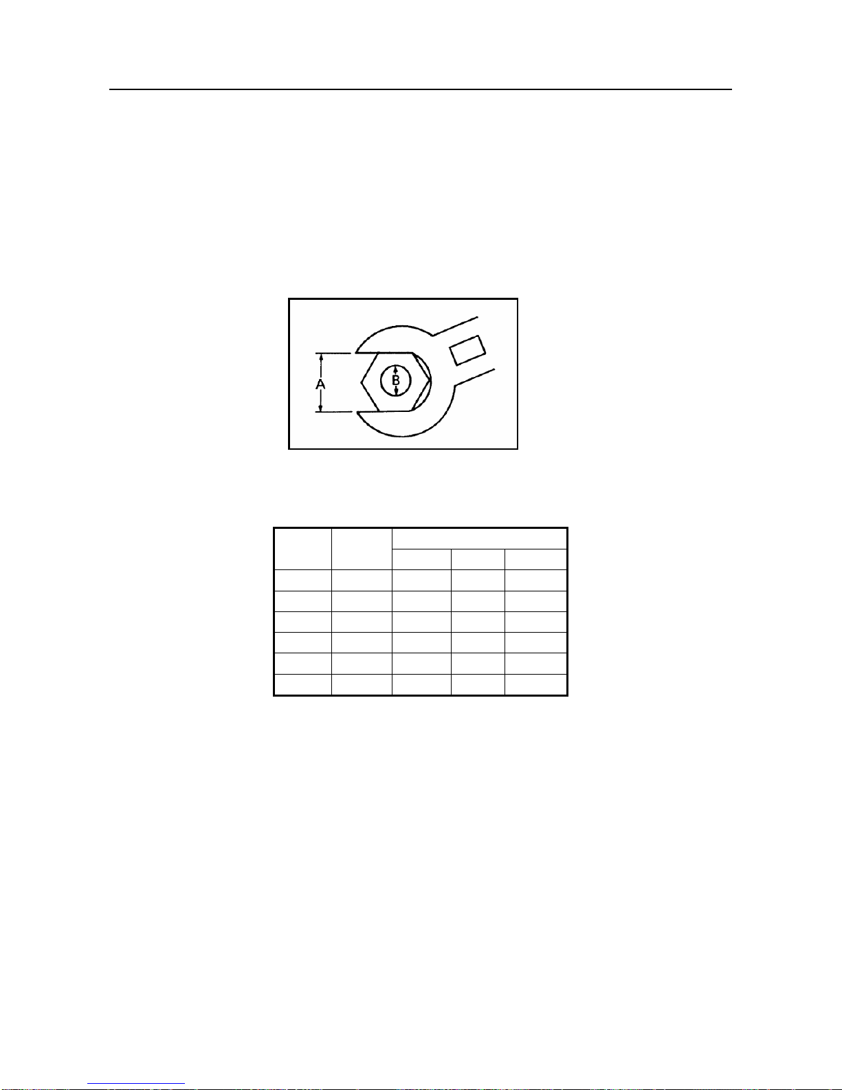
GENERAL SPECIFICATIONS
2-21
GENERAL TIGHTENING TORQUE SPECIFICATIONS
This chart specifies tightening torques for standard fasteners with a standard ISO thread pitch.
Tightening torque specifications for special components or assemblies are provided for each chapter of
this manual. To avoid warpage, tighten multi-fastener assemblies in a crisscross pattern and progressive
stages until the specified tightening torque is reached. Unless otherwise specified, tightening torque
specifications require clean, dry threads. Components should be at room temperature.
A: Distance between flats
B: Outside thread diameter
General tightening torques A
(nut)
B
(bolt)
Nm m · kg ft · lb
10 mm 6 mm 6 0.6 4.3
12 mm 8 mm 15 1.5 11
14 mm 10 mm 30 3.0 22
17 mm 12 mm 55 5.5 40
19 mm 14 mm 85 8.5 61
22 mm 16 mm 130 13.0 94
Page 95
GENERAL SPECIFICATIONS
2-22
LUBRICATION PIONTS AND LUBRICANT TYPES
ENGINE
Lubrication points Lubricant
Oil seal lips
Bearings
O-rings
Piston, piston ring
Piston pin
Buffer boss and balancer drive gear
Crankshaft seal and spacer
Valve stem
Valve stem end
Rocker arm shaft
Rocker arm
Camshaft lobe and journal
Oil pump assembly
Oil filter cartridge O-ring
Starter idle gear shaft
Starter wheel gear
Clutch housing assembly shaft end
Clutch carrier assembly
One-way clutch bearing
Middle driven shaft splines
Drive axle, driven sprocket, high wheel gear, and low wheel gear
Middle drive gear and clutch dog shift fork groove
Driven chain/sprocket
Shift drum
Shift fork guide bar
Shift drum stopper ball
Shift lever 2 assembly
Shift lever 1
Shift lever 1 and shift lever 2 assembly mating surface
Page 96
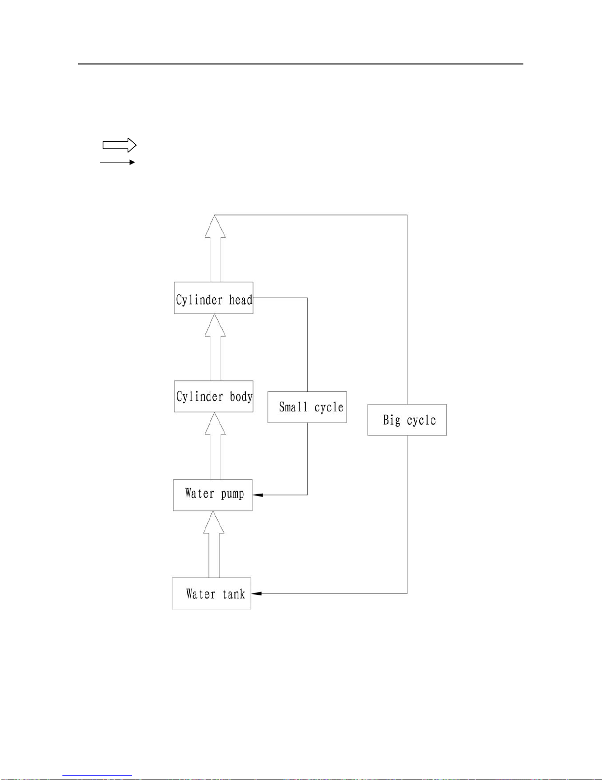
GENERAL SPECIFICATIONS
2-23
HYDROGRAPHIC CHART
Hydrographic chart
:Pressure
:splash
Page 97
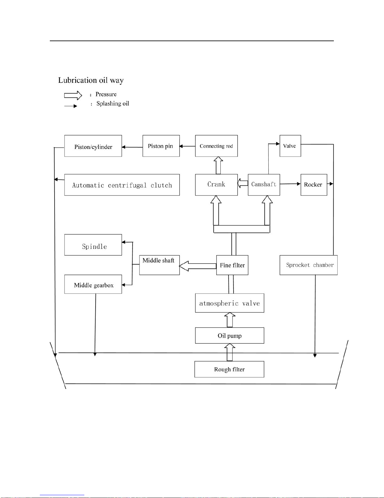
GENERAL SPECIFICATIONS
2-24
LUBRICATION OIL WAY
Page 98
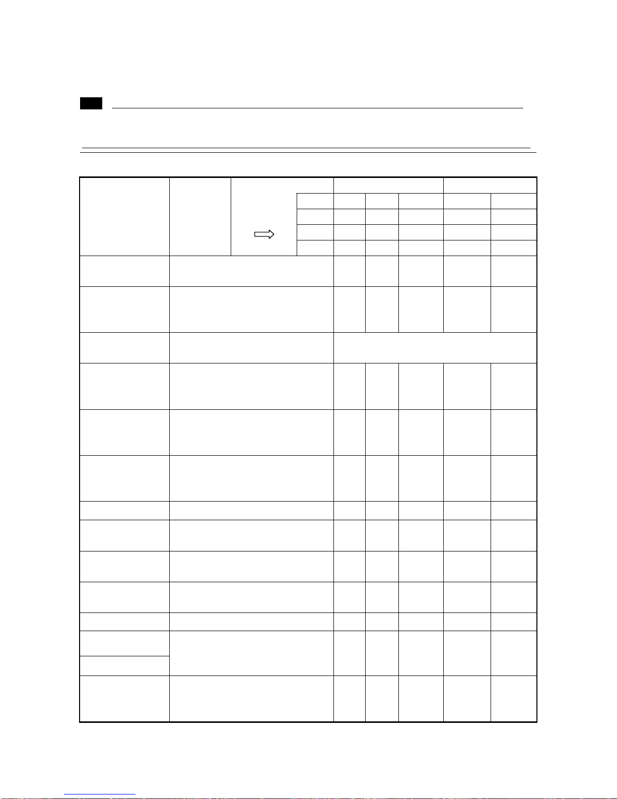
3-1
MAINTENCE AND ADJUSTMENT OF THE UTV
Note:
The correct maintenance and adjustment are necessary to ensure vehicle and normal driving
The repair personnel should be familiar with the contents of this article.
Maintenance schedule
EVERY INITAL
month 1 3 6 6 12
km 320 1,200 2,400 2,400 4,800
(mi) (200) (750) (1,500) (1,500) (3,000)
ITEM ROUTINE
Whichever
comes first
hours 20 75 150 150 300
Val ves
· Check valve clearance.
· Adjust if necessary.
○ ○ ○ ○
Spark plug
·Check condition.
· Adjust gap and clean.
· Rep; ace if necessary.
○ ○ ○ ○ ○
Air filter element
· clean.
·Replace if necessary.
Every20-40hours
(More often in wet of dusty areas.)
Carburetor*
· Check and adjusted idle speed/starter
operation.
·Adjust if necessary.
○ ○ ○ ○
Crankcase breather
system*
·Check breather hose for cracks of
damage.
·Replace if necessary.
○ ○
○
Exhaust system*
· Check for leakage.
· Tighten if necessary.
· Replace gasket(s) if necessary.
○
○
Spark arrester ·Clean. ○ ○ ○
Fuel line*
·
Check fuel hose for cracks or damage.
·Replace if necessary.
○ ○ ○
Engine oil ·
Replace.(Warm engine before draining.)
○ ○ ○ ○
Engine oil filter
cartridge
· Replace. ○ ○ ○ ○
Engine oil strainer* ·Clean. ○ ○ ○ ○
Final gear oil
Differential gear oil
· Check oil level /oil leakage.
· Replace
○ ○
Front brake*
· Check operation/ fluid leakage.(See
NOTE page 8).
· Correct if necessary.
○ ○ ○ ○ ○
Page 99
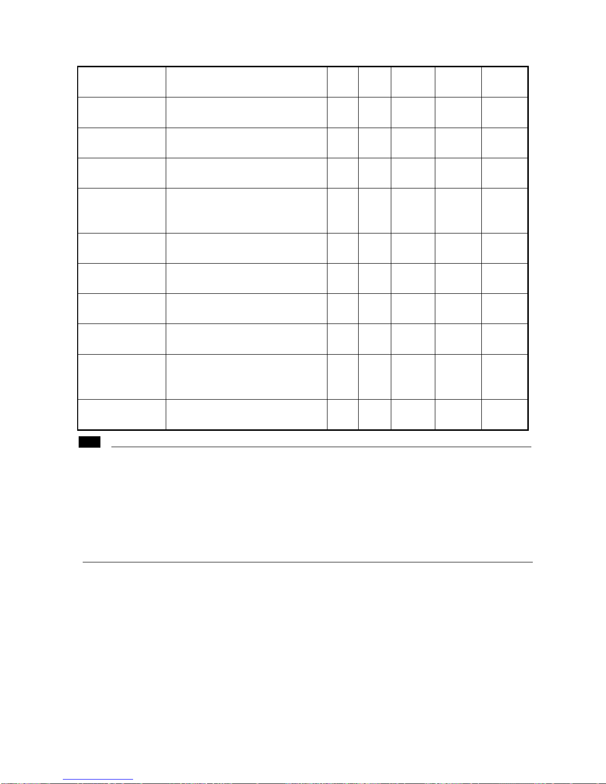
3-2
Rear brake*
· Check operation.
· Adjust if necessary.
○ ○ ○ ○ ○
Select lever safety
system cable
·Check operation.
· Adjust if necessary.
○ ○ ○
V-belt*
· Check operation.
· Check for cracks or damage.
○ ○ ○ ○
Wheel
·Check balance/damage/
· Repair if necessary.
○ ○ ○ ○
Wheel bearing*
·
Check bearing assemblies for looseness
/damage.
·Replace if necessary.
○ ○ ○ ○
Front and rear
suspension*
· Check operation.
·Correct if necessary.
○ ○
Steering system*
·
Check operation./Replace if damaged
·
check to
e-in./Adjust if necessary.
○ ○ ○ ○ ○
Drive shaft universal
joint*
· Lubricate with lithium–soap–based
grease.
○ ○ ○
Axle boots*
· Check operation.
· Replace if damaged.
○ ○ ○ ○ ○
Fittings and
fasteners*
·
Check all chassis fittings and
fasteners.
·Correct if necessary.
○ ○ ○ ○ ○
Lights and switches*
· Check operation.
· Adjust headlight beams.
○ ○ ○ ○ ○
Note:
·Recommended brake fluid: DOT 4
·Brake fluid replacement:
·When disassembling the master cylinder or caliper, replace the brake fluid. Normally check the
brake fluid level and add fluid as required.
·On the inner parts of the master cylinder and caliper, replace the oil seals every two years.
·Replace the brake hoses every four years, or if cracked or damaged.
Page 100
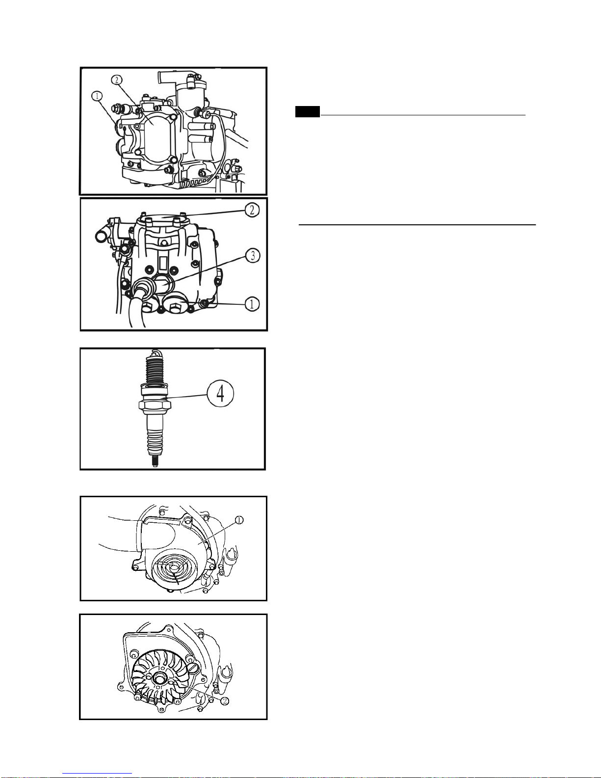
3-3
ENGINE
ADJUSTING THE VALVE CLEARANCE
Note:
·The valve clearance must be adjusted when the
engine is cool to the touch.
·Adjust the valve clearance when the piston is at
the Top Dead Center TDC) on the compression
stroke.
· Remove:
·driver seat
·passenger seat
·console
1. Remove following parts:
① Valve cover(intake)
② Valve cover(exhaust)
③ spark plug cap
④ spark plug
2. Remove the cooling fan:
① Fan cover
② Fan impeller
③ As manhole covers
 Loading...