

Page 1
Subwoofer Manual
Features
Wireless Technology.
Contrary to popular belief, subwoofer placement is critical in order to achieve optimal sound quality. Incorporating
wireless technology in our subwoofer greatly enhances your ability to position the subwoofer for optimal performance
while still keeping the spouse happy.
This woofer uses a patented XBL2 ™ motor design that has an incredibly linear motor force. The motor force (BL)
stays within 2% over a wide +/- 20 mm excursion. Most woofers with Xmax of +/- 20 mm would be lucky to have
the BL within 2% over a +/- 5 mm range!
A very high headroom BASH®amplifier is used to fully utilize the ultra low distortion, ultra high output capability of
the woofer. This amplifier is capable of delivering up to 1000 W rms short- term power.
Now included are more connectivity options than any other subwoofer we know of, at any price! Inputs include
balanced XLR, unbalanced RCA, wireless, and speaker level. This flexibility allows you to use the subwoofer in
recording studios, high end two channel systems, and state-of-the-art home theater systems.
Traditionally it has been difficult to get loud, clean, ultra deep bass from a compact enclosure. The ULS-15 changes
that. It gives you loud, clean, ultra deep bass from a compact, beautifully-finished enclosure.
An Ultra Low Frequency (ULF™) trim control allows you to maintain accurate deep bass response in virtually any
room, no matter what shape or size.
Ultra Linear Woofer.
Powerful BASH®Amplifier.
Great Connectivity.
Compact Enclosure.
Accomodates All Room Sizes.
Page 2
2
10. Protect the power cord from being
NO USER SERVICEABLE
PARTS ARE INSIDE.
walked on or pinched particularly at
plugs, convenience receptacles, and the
point where they exit from the apparatus.
11. Unplug this apparatus during
lightning storms or when unused for
long periods of time.
12. Refer all servicing to qualified service
personnel. Servicing is required when
the apparatus has been damaged in any
way, such as power-supply cord or plug
is damaged, liquid has been spilled or
objects have fallen into the apparatus,
the apparatus has been exposed to rain or
moisture, does not operate normally, or
has been dropped.
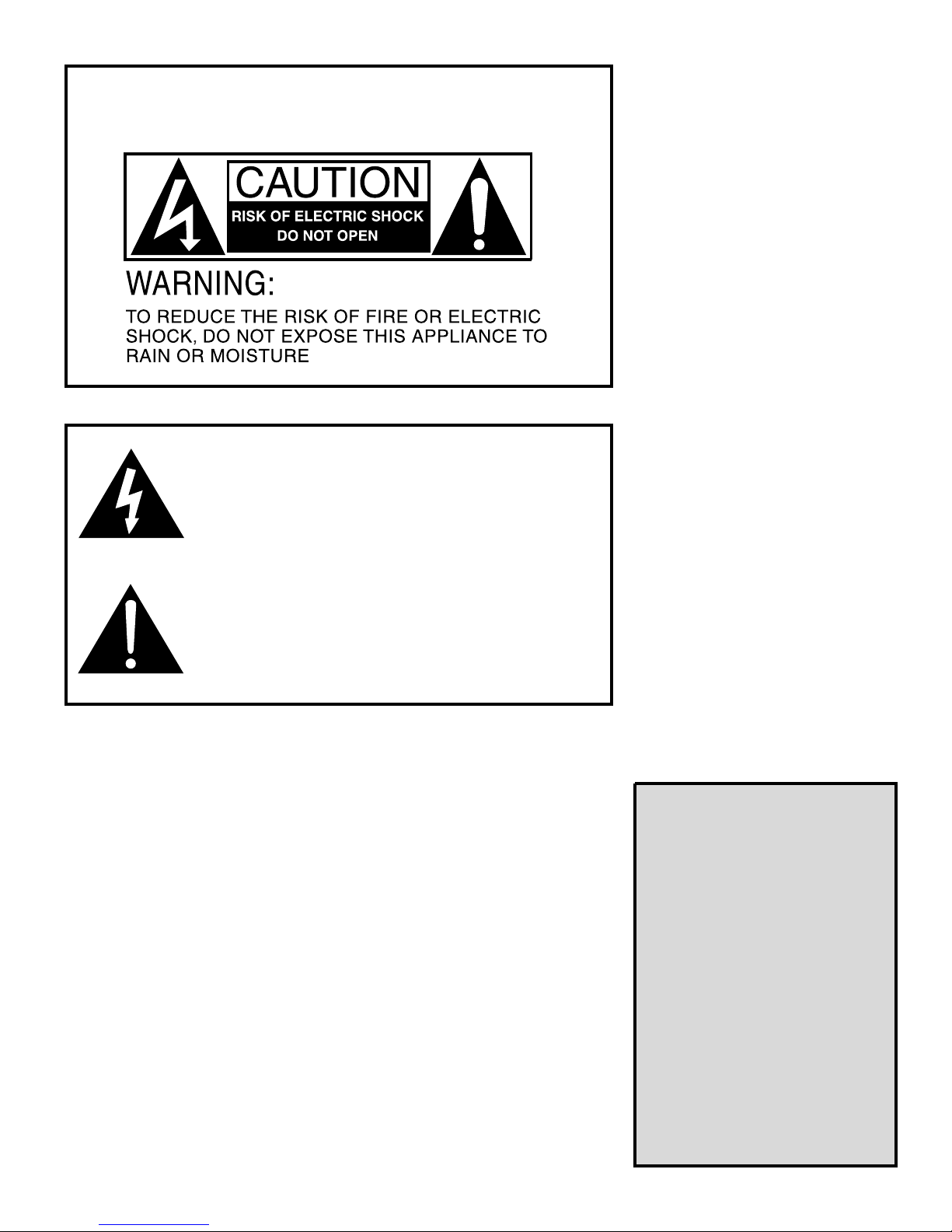
The lightning flash with arrowhead symbol within an equilateral triangle is
intended to alert the user to the presence of uninsulated “dangerous voltage”
within the product’s enclosure that may be of sufficient magnitude to constitute
a risk of electric shock to persons.
Le symbole éclair avec point de flèche à l’intérieur d’un triangle équilatéral
est utilisé pour alerter l’utilisateur de la presence à l’intérieur du coffret de
“voltage dangereux” non isolé d’ampleur suffisante pour constituer un risque
d’éléctrocution.
The exclamation point within an equilateral triangle is intended to alert the
user to the presence of important operating and maintenance (servicing)
instructions in the literature accompanying the product.
Le point d’exclamation à l’intérieur d’un triangle équilatéral est employé pour
alerter les utilisateurs de la présence d’instructions importantes pour le
fonctionnement et l’entretien (service) dans le livret d’instruction
accompagnant l’appareil.
Important Safety Instructions
1. Read these instructions.
2. Keep these instructions.
3. Heed all warnings.
4. Follow all instructions.
5. Do not use this apparatus
near water.
6. Clean only with dry cloth.
7. Do not block any ventilation
openings. Install in accordance with
the manufacturer's instructions.
8. Do not install near any heat sources
such as radiators, heat registers, stoves,
or other apparatus (including amplifiers)
that produce heat.
9. Do not defeat the safety purpose of
the polarized or grounding-type plug.
A polarized plug has two blades with
one wider than the other. A grounding
type plug has two blades and a third
grounding prong. The wide blade or
the third prong are provided for your
safety. If the provided plug does not fit
into your outlet, consult an electrician
for replacement of the obsolete outlet.
13. WARNING: To reduce the risk of fire
or electric shock, this apparatus should
not be exposed to rain or moisture and
objects filled with liquids, such as vases,
should not be placed on this apparatus.
14. To completely disconnect this
equipment from the mains, disconnect
the power supply cord plug from the
receptacle.
15. The mains plug of the power supply
cord shall remain readily operable.
TABLE OF
CONTENTS
UNPACKING . . . . . . . . . . . . .3
PLACEMENT . . . . . . . . . . . .3
HOOKUP . . . . . . . . . . . . . . .4
AMPLIFIER PANEL . . . . . . .5
VOLUME LEVEL . . . . . . . . .6
CROSSOVER . . . . . . . . . . . .6
FINE TUNING . . . . . . . . . . . .6
TROUBLESHOOTING . . . . .8
REPAIR . . . . . . . . . . . . . . . . .9
SPECIFICATIONS . . . . . . . .10
WARRANTY . . . . . . . . . . . .10
Page 3
Set-Up
Step 1: Unpacking
Before unpacking, inspect the carton for puncture holes, crushed corners, etc. Take photos of any potential
shipping damage before proceeding to unpack. Take note of which corner or wall the damage is on so you
can check the corner/side of the subwoofer nearest the external damage.
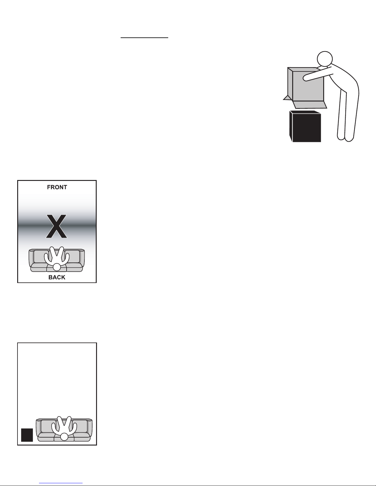
This subwoofer is very heavy. Be sure to get someone to help you unpack. If you have a hard floor, unpack
the subwoofer on a throw rug or blanket to avoid unwanted scuffing or scratching. Find the top of the box
and open it. Holding the flaps open, roll the box over until it is upside-down. Lift the box off.
Lift the subwoofer off the foam corners and place it on the carpet/blanket. Remove the protective bag and
inspect for damage. If all looks fine, turn the subwoofer so the bottom faces up (the face with the four screw
holes). Screw in the feet. If the subwoofer has a protective stick-on plastic, leave it on until you decided to
keep the subwoofer for good. Any returned product with scratches, etc. will be subject to a restocking fee.
Upright the subwoofer and move it to the desired location.
Step 2: Placement
3
Avoid placing the subwoofer
halfway between the front
and back walls. Avoid sitting
there as well.
Contrary to popular belief, placement is extremely important. It can dramatically affect the bass
quality and quantity. An optimally placed subwoofer is much more powerful and better sounding
than a poorly placed one.
Important Guidelines
• This subwoofer does not have magnetic shielding and has a HUGE magnet (35 lbs!). Keep the subwoofer at least 5 ft away from CRT TVs or video displays. LCD, plasma, and DLP TVs are not
affected, and the subwoofer can be placed next to these items with no magnetic interference. Keep
the subwoofer at least 2 ft away from computers in order to prevent the hard drive from being erased.
Rules of thumb for placement
• Avoid the center of the room: In general, avoid placing the subwoofer half way between the front
and back walls. You should avoid sitting in the middle as well.
• Use near-field placement: You get the tightest upper bass and the most punch if you can place the
subwoofer close to you. By being close to the subwoofer, you get high SPL without requiring a lot
of power. This helps to minimize annoyance to your neighbors as well. The direct- to- reflected ratio
is also higher, helping to reduce room effects. One situation where near-field placement may not work
best is when your room is very shallow. In a shallow room (less than 15 ft front to back), placing the
sub close to you will lead to a dip in the low bass response.
• Corner placement: If near-field placement is not optimal, then corner placement is a great alternative.
A front corner furthest from openings is generally optimal for deep bass reproduction.
• Placement in entertainment centers: This is acceptable as long as you can fire the woofer straight
into the room, and you have at least 1˝ spacing on the sides, top and back (measured from the heat
sink). The air in the cavity must be able to circulate with the outside air to get proper cooling. Make
sure the entertainment center will not vibrate and rattle. Use the rubber feet if placing the subwoofer
in an entertainment center.
• Direct line of sight between subwoofer and wireless transmitter: If you are using the wireless
connection, the signal is most reliable if there is nothing blocking the subwoofer from the wireless
transmitter. Also, the transmitter should not be too close to the ground, preferably 18˝ or higher. Do not
worry too much if these criteria cannot be met. We have tested thise subwoofer with the transmitter on
Corner and nearfield
placement usually sound best.
the ground, and in a room with four walls between the transmitter and the subwoofer, and the wireless
technology still works fine.
Page 4
4
Step 3: Hookup
We will refer to receivers, integrated amplifiers, and preamps as controllers. Take a look at the back of your controller.
The output connectors available determine the best method
of hooking up your subwoofer.
Method A. Connecting to controllers
with a SUBWOOFER or LFE output
If you have this, you should use it. All Dolby Digital, DTS,
THX, and Dolby True HD equipped controllers have a low
level Subwoofer pre-out (not to be confused with a subwoofer
input – many customers have hooked up their subwoofer to
the subwoofer input on their controller only to get no sound!).
This offers the easiest and best connection.
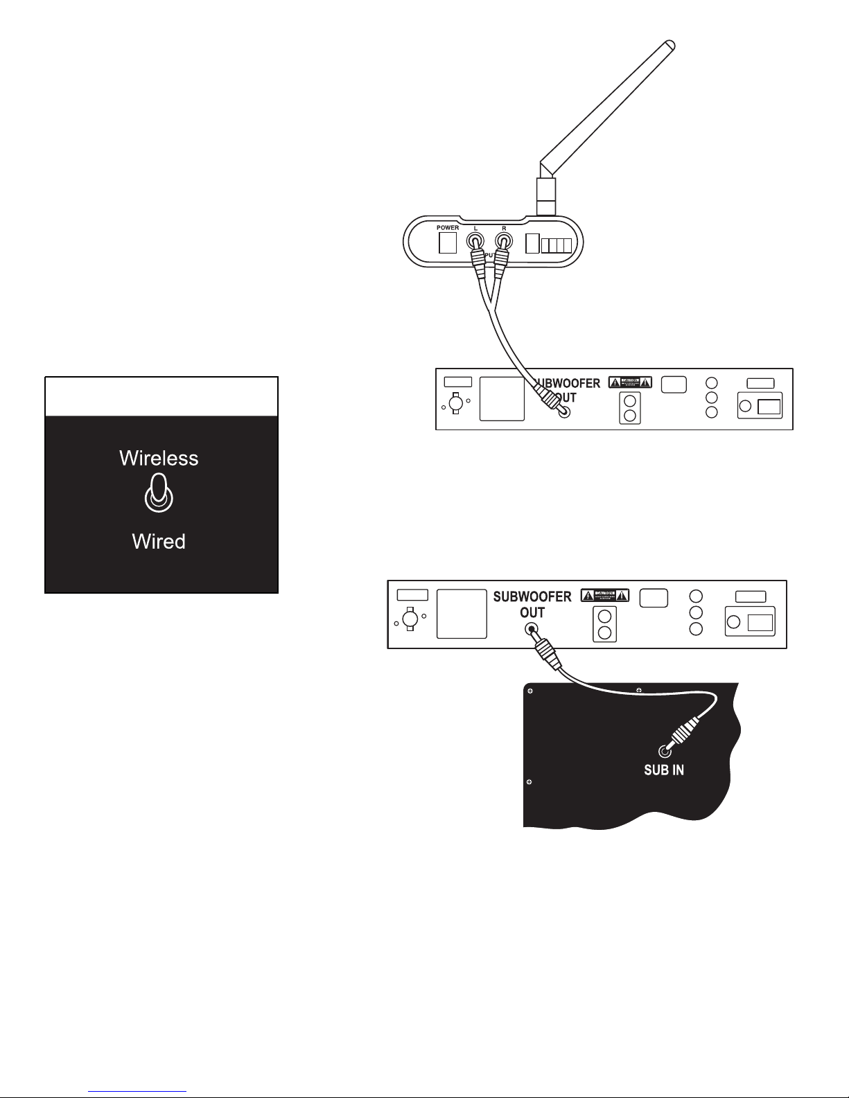
Connect the subwoofer pre-out to both inputs on the wireless transmitter using a splitter.
Set the wireless channel on the transmitter so that it is the same as that on the subwoofer.
Set the wired/wireless switch on the subwoofer to ‘Wireless
as practical, and away from metal surfaces if possible.
Wired Connection
Connect the subwoofer pre-out to either one of the two
RCA low level inputs on the subwoofer. If your controller has a balanced output, connect to either one of
the two XLR balanced inputs.
Enable your subwoofer out on your controller. We highly
recommend setting all your speakers to SMALL so all
bass will be routed to the subwoofer, freeing the main
amp and main speakers from the rigorous demands of
reproducing bass.
Method B. Connecting to controllers with HIGH LEVEL speaker outputs.
Wireless Connection
’. Place the transmitter as high
Use this method only if you do not have any other choice. Integrated amplifiers or stereo receivers with no pre-outs fall in this category.
The subwoofer will operate in bass augmentation mode. i.e., the main speakers will be running full-range. You dial in the subwoofer to
come in just where the main speakers start to fade out. Since the subwoofer uses its own amplifier, and has a high input impedance, it
will not alter the loading on your main amplifier.
It is important to know if your controller has true ground or not. Bridged amplifiers, and amplifiers like Carver (which inverts phase to
one channel making their black terminal on one channel the signal instead of ground) should not be used. Similarly, digital amplifiers
that have unfiltered outputs are also not suitable.
Since the subwoofer will not be drawing any significant current, any gauge wire will do. No need for heavy gauge wires.
Page 5
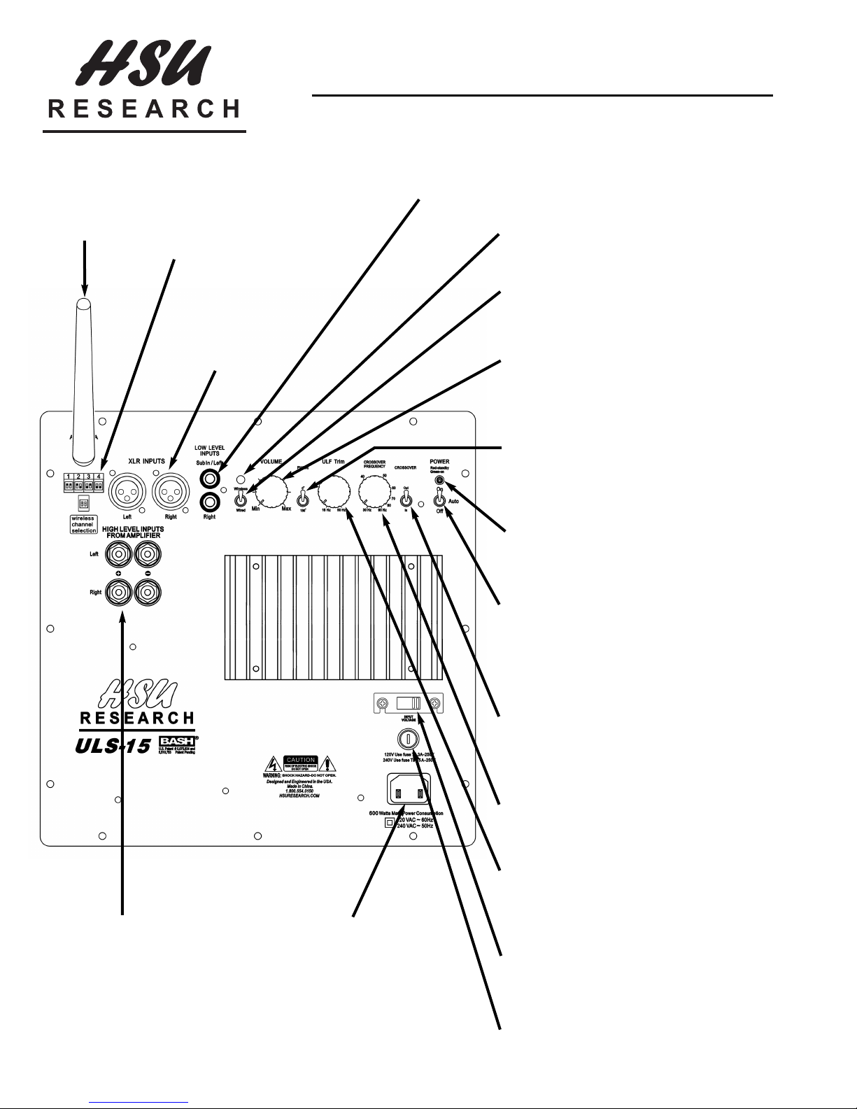
Antenna:
Orient for optimal reception.
Usually vertical
position is good.
ULS-15 Amplifier Panel
Wireless Channel Selection:
By default, it is set to channel 1.
Unless you have problems with
interference, leave it on channel 1.
XLR Inputs:
If your processor
has balanced outputs, use these.
5
Low Level/Sub Inputs:
For Dolby Digital systems, connect the SUBWOOFER OUT to
either of these inputs. For stereo-only systems, you may connect the
left and right channels to both inputs as explained in the manual.
Wireless Signal Indicator:
LED is on (green) when the wireless receiver and transmitter establishes connection.
Wired/Wireless Switch:
Select “Wireless” if you use the wireless feature.
Otherwise, select “Wired.”
Volume Control:
Set this to the second line up from minimum. Use the
subwoofer level control on your controller to fine tune.
If your controller does not have a subwoofer level control, then adjust this to get the desired bass level.
Phase Switch:
Depending on your system and room, the bass in the
crossover region may be smoother if you reverse the
phase of the subwoofer. See the Fine Tuning section of
the manual.
High Level from Amplifier:
If your controller does not have low
level outputs (SUBWOOFER, LFE,
or full-range preamp outputs), use
these color coded connectors. Run
speaker wire from your amplifier or
receiver’s speaker terminals to tap
the signal.
Power Input:
This is an IEC socket. Connect
the supplied power cord here. If
your country uses a different
power cord, get one locally.
Power Indicator:
When the subwoofer is ON, this LED light will be green.
When the subwoofer is in STANDBY mode, it will be red.
Power / Auto-on Switch:
When in the ON position, the subwoofer will stay on at
all times. In AUTO mode, material with bass will quickly turn the subwoofer on. After around 15 - 30 minutes
of inactivity, the subwoofer will automatically go into
STANDBY mode.
Crossover Defeat Switch:
If you are using a SUBWOOFER or LFE output, you can
disengage the crossover by switching it to OUT. The
crossover should be switched to IN when using high level
inputs or two channel low level inputs.
Crossover Frequency Control:
This low-pass crossover controls what frequencies are
handled by the subwoofer.
ULF Trim:
This compensates for room gain at very low frequencies. Smaller rooms have more boost in the low bass.
Setting this control to 16 Hz gives flat response to 16 Hz
outdoors. Adjust to suit your room.
Voltage Selector Switch:
For 100 - 120V line voltage, set to 120V. For 220 250V, set to 240V.
Removable Fuse Holder:
By pushing in and turning counter-clockwise, you can
remove and replace the fuse. Use only the correctly
rated 5 x 20 mm replacement fuses.
Page 6
6
Method C. Connecting to controllers with PRE-OUTs.
This method is for stereo systems with low level pre-outs.
Wireless Connection
Connect the low level pre-outs to the two inputs on the wireless transmitter. Set the wireless channel on the transmitter so that it is the
same as that on the subwoofer. Set the wired/wireless switch on the subwoofer to ‘Wireless’. Place the transmitter as high as practical,
and away from metal surfaces if possible.
Wired Connection
Connect the low level pre-outs to the two RCA low level inputs on the subwoofer. If your controller has balanced outputs, connect to
the two XLR balanced inputs on the subwoofer.
This approach will also be in augmentation mode unless you purchase our high pass filter to keep bass from your main speakers (unbalanced
systems only). Refer to the high pass filter instructions on how to do that.
Step 4: Vo lume Level
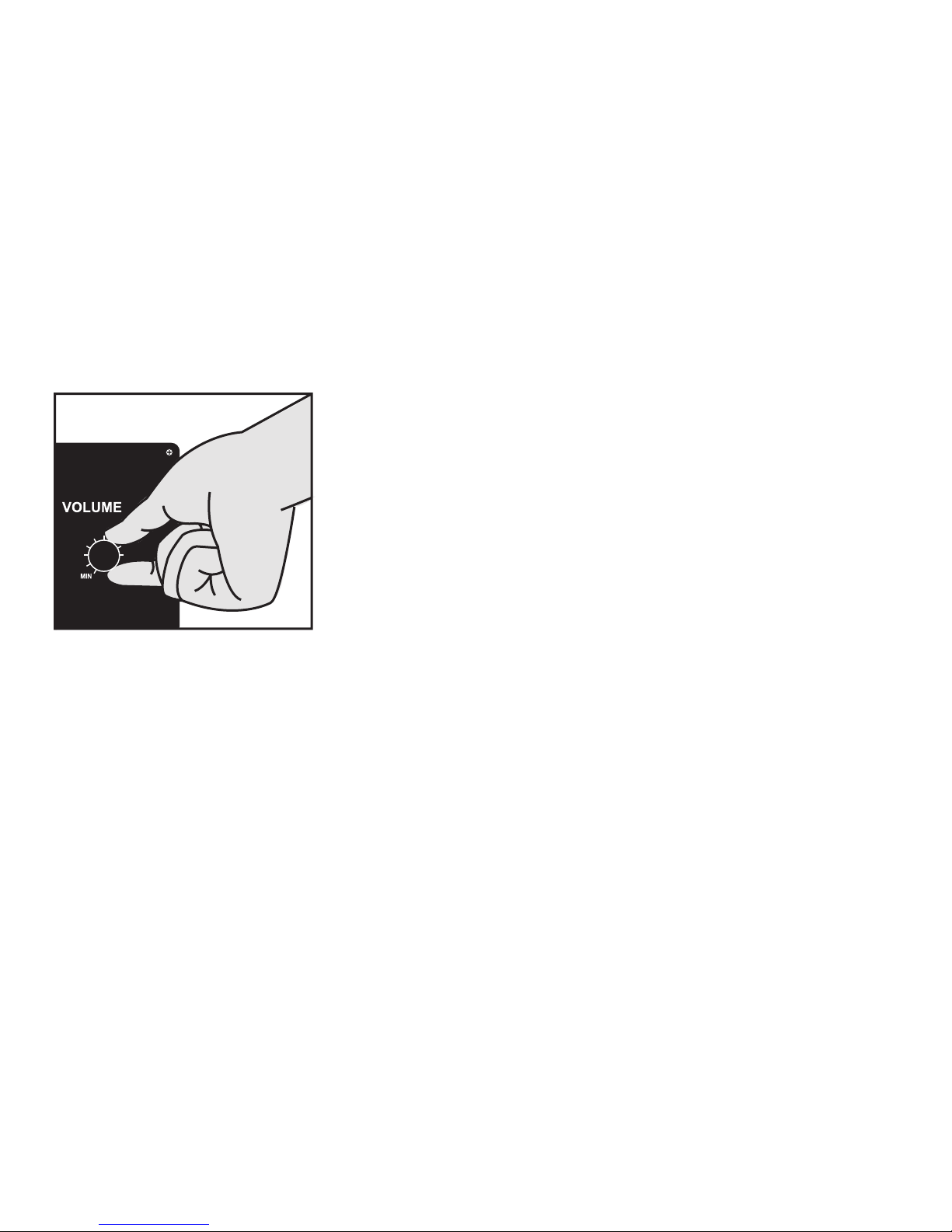
To start, set the volume level on the subwoofer at around 11 o’clock. Setting the volume
level much higher than that will make the auto-on function not work properly. Auto-on
level sensing is before the volume control. Hence setting the volume level too high on the
subwoofer will lead to very low input levels for the auto- on circuit, and will make it harder for the sub to turn on.
To set the subwoofer level subjectively, set the subwoofer to the highest level where it
sounds nice and bass and kick drums still sound tight and non-boomy. For home theater
applications, most people like the bass to be a bit higher than for music. 3 dB higher is a
good choice, if your receiver allows you to set levels for each source.
Step 5: Crossover
If your controller has bass management and has a steep crossover slope, set the crossover switch on the subwoofer to ‘Out’. If your controller
has a gentle crossover slope ( 12 dB/Oct or less), set the crossover switch on the subwoofer to ‘In’, and set the crossover frequency knob
on the subwoofer to the same frequency that was selected on your controller.
For bass augmentation mode (method B or C), set the crossover switch on the subwoofer to ‘In’ and crossover frequency knob set to
where your main speakers start to fade out. Adjust the level for best blend.
Step 6: Fine Tuning
ULF Trim
When the room is small, you get room gain effect that boosts deep bass. In a small space like a car, bass below 80 Hz would start to rise.
We have added a ULF Trim control on the subwoofer in order toto compensate for this room gain effect. For very large rooms or very
open floor plans, set the trim control to 16 Hz. For very small rooms that are enclosed, set the trim control to 50 Hz, or somewhere inbetween for moderately sized rooms.
Depending on the absolute phase of your main speakers and amplifier, and the distances of the subwoofer and main speakers from the
listening position, the bass in the crossover region may be smoother if you reverse the phase of the subwoofer. The phase switch position
that give a fuller bass in the crossover range is the correct one.
If your controller allows you to set the distance of the subwoofer and main speakers, set these correctly first. This will also time align
the subwoofer to give you the most seamless and tight bass.
Setting the Phase
Page 7

Using the CDR to Fine Tune
You can use the test tones on the CDR we provide to fine tune the subwoofer. 80 Hz is the crossover frequency used for thise example:
1. Play the 50 Hz test tone.
2. Adjust the volume on the controller to get 80 dB reading on the SPL meter placed at the listening chair.
3. Play tones from 32 Hz up to 200 Hz. Note the SPL reading on the meter at each frequency.
4. Take the average of the four tones below 80 Hz: – 63, 50, 40 and 32 Hz.
5. Take the average of the four tones above 80 Hz:. – 100, 125, 160 and 200 Hz.
6. If the average of the four tones below 80 Hz is, say, 5 dB higher than the average of the upper range, adjust the subwoofer level down 5 dB.
7. If your controller has a subwoofer out level, use this to adjust the level. If it does not, play the 50 Hz tone and adjust the subwoofer
volume control to get the desired change in level.
If you are using the Radio Shack SPL meter, compensate for the meter’s deep bass deficiency. The older analog Radio Shack meters are
down 12 dB at 16 Hz, 7 dB at 20 Hz, 4 dB at 25 Hz, and about 2 dB down at 32 Hz. Add these numbers to the actual readings you get
from the meter. The newer digital meters are off even more. Add at least 2 dB to the above numbers.
Equalizing the Subwoofer
Some controllers have built-in equalizers for the subwoofer channel. You can use these to reduce the major room modes (peaks). It is generally not recommended to boost bass to compensate for nulls (dips) as this will use up too much power and risk damaging the subwoofer.
7
Page 8

8
Troubleshooting
If you think your subwoofer has a problem, please do everything you can to confirm the problem before contacting us for service,
including reading through the troubleshooting section. Many times the problem actually is caused by other items in the system or the
subwoofer’s interaction with those items. Much of the time, the service department will not be able to reproduce the error.
Problem Cause Solution
Humming or
buzzing noise
Subwoofer goes into
STANDBY mode
while material is
playing.
You have an amplifier problem.
Your speaker wires or interconnects are
the cause.
A light dimmer or other triac based (SRC)
device is on the same AC circuit.
You have a problem with other equipment.
The source is not providing enough signal.
• Disconnect all interconnects from the amplifier. If still
hums, call/email technical support.
• It is possible that some cables have a poor or broken
ground due to poor construction, oxidation, or damage.
Also, poorly shielded cables can potentially pick up
noise. Tr y another interconnect or speaker wire. Also,
move the signal cable away from AC cables, power
transformers, or other EMI sources.
• Use an AC line filter or plug the unit into a different circuit.
• If hum goes away when interconnects are disconnected,
the hum is coming from the rest of your equipment.
Add them back one piece at a time. The one that causes
the system to hum is the source of the hum.
• The unit is going into STANDBY mode during the quiet
passages. Tr y turning the source signal up. On a Dolby
Digital receiver, turn the SUBWOOFER level up in the
SPEAKER SET-UP menu. After you turn the signal up, turn
down the volume knob on the subwoofer to compensate.
• An alternative is to turn the subwoofer ON/AUTO/OFF
switch to the ON position. It does not use any more
power and does not affect reliability.
AC power is not getting to the amplifier.
No output from the
subwoofer (the LED
does not light up).
The amplifier’s fuse is blown.
The amplifier has gone into
self-protect mode.
• Check that the power cord is plugged in securely at both
ends and make sure that the power outlet the subwoofer
is plugged into is working.
• Check the fuse. The fuse is located on the amplifier, near
the power plug. Unplug the power cord and remove the
fuse holder with a flat head screwdriver. If the fuse is
blown, the output transistors are probably damaged.
Call/e-mail technical support for authorization to send
the amplifier back for service.
• Unplug the power cord. Wait 2-3 minutes. Plug the power
cord back in. It should power up and work normally.
Page 9

Problem Cause Solution
• Recheck the connections between the source and the subwoofer. If you
are using a receiver with Dolby Digital, make sure you are connecting
to the subwoofer pre-out and not the subwoofer input on the receiver.
If you are using the wireless connection, make sure the transmitter is
The subwoofer is not receiving a
signal.
No output from the
subwoofer (LED
lights up red).
Subwoofer amplifier is faulty.
powered (l.e.d. lights up), and the ‘Wireless/Wired’ switch is set to
‘Wireless’. Make sure the channel selection are the same on the transmitter and receiver. Check and see if the led above the ‘Wireless/Wired’
switch is lit up solid green. If not, move the antenna, transmitter, and
subwoofer to get better reception. If you are using the wired connection, make sure the 'Wired/Wireless' switch is set to 'Wired'.
• With the volume on the subwoofer turned to a low setting, try
plugging the subwoofer directly into a DVD player's analog output,
ipod, or other MP3 player or lightly touching the unplugged end of
the input cable. If you hear noise from the subwoofer, the problem is
with your connection to the system. If you hear no noise, try turning
the volume on the subwoofer up some more. If you still hear no
noise, call/e-mail technical support for authorization to send the
amplifier back for service.
9
No output from the
subwoofer (LED
turns green).
Little or no sound
from one main
speaker.
Bass output from
subwoofer is low.
Subwoofer
thumps when the
system is being
turned on and off.
Connection between subwoofer
amplifier and woofer is faulty.
Driver or amplifier is faulty.
You used speaker level connections
and have mixed up the polarity of
the wires, thus shorting one channel
of the main amplifier.
You used speaker level connections
and one or both your main amplifier’s
‘ - ’ are not true ground.
Level on subwoofer or receiver’s
subwoofer output is too low.
Noise is being generated by upstream equipment.
• Email [email protected] or call (800)554-0150
• Email [email protected] or call (800)554-0150
• Correct the polarity of the speaker wires by matching the +/- from
the receiver/amplifier to the +/- of the subwoofer’s speaker level input.
• Connect only to the channel that has a true ground ‘ - ’. If neither
channel has a true ground ‘ - ’, e-mail/call technical support.
• Increase the volume of the subwoofer and the subwoofer level or
LFE level on the receiver or other source. It is best to set the level
of the subwoofer relative to the other speakers using a test disk and
a Radio Shack SPL meter, or built-in tones on your pre-amp/processor. See “Volume Level” in Step 4.
• When you shut down your equipment, turn off the subwoofer first.
When powering up, turn on the subwoofer last.
If your unit needs service, please re-review the troubleshooting section first.
Contact tech support via e-mail (24/7) or call 1-800-554-0150 9am to 5pm Pacific time, Monday through Friday.
We will try and respond to emails sent to [email protected] within two business days.
Repair
Page 10
10
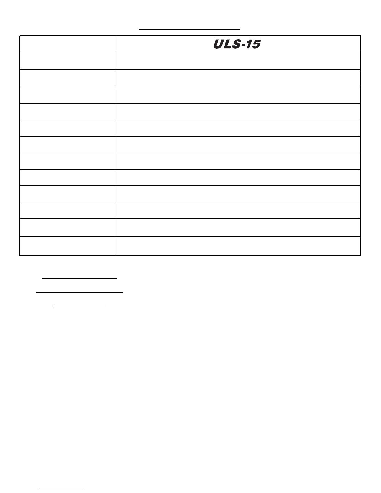
Specifications
Frequency Response
Woofer Size
Amplifier Power
Crossover Frequency Range
Crossover Slope
Crossover Type
Phase
ULF Trim
Inputs
Dimensions
Ship Weight
+/–1 dB 15 – 200 Hz
15 inches
1000 W rms short-term
30-90 Hz, bypassable
24 dB/Oct
Linkwitz-Riley, Low Pass only
0°/180°
16 - 50 Hz
Balanced L/R, unbalanced L/R, speaker level L/R, Wireless 2.4 GHz L/R
18˝ cube (enclosure only), 19˝ (h) x 18˝ (w) x 19.5˝ (d) with feet, grille and heatsink
82 lbs
Power Outlet Requirement
HSU Speaker
System Limited
Warranty
If the
speaker system proves to be
defective in materials or workmanship
within seven years from the date of the
original customer’s purchase, or the
amplifier within two years, we will, at our
option, repair or replace the defective
product.
*DISCLAIMER
THE WARRANTY STATED HEREIN IS IN LIEU
OF ALL OTHER WARRANTIES, EXPRESS OR
IMPLIED, INCLUDING MERCHANTABILITY
AND FITNESS FOR PARTICULAR PURPOSE AND
ALL OTHER LIABILITIES AND OBLIGATIONS
OF
HSU
, ALL OF WHICH ARE EXPRESSLY DISCLAIMED.
NOT HEREBY MAKE ANY OTHER REPRESENTATION, WARRANTY OR COVENANT WITH
RESPECT TO THE CONDITION, QUALITY,
DURABILITY, DESIGN, OPERATION, CAPACITY,
FITNESS FOR USE OR SUITABILITY OF THE
SPEAKER SYSTEMS.
HSU
HAS NOT MADE AND DOES
5A, 120V/2.5A, 240V, 120/240V selector
Exclusion of
Certain Damages
HSU’s liability for any defective product is
limited to repair or replacement of the product at our option. HSU shall not be liable for
incidental or consequential damages of any
kind or character because of product defects.
Some states do not allow limitations on how
long an implied warranty lasts and/or do not
allow the exclusion or limitation of incidental
or consequential damages, so the above limitations and exclusions may not apply.
This Warranty Does
Not Cover:
Damage caused by abuse, accident, misuse, negligence, or improper operation.
Products that have been altered or modified.
Any product whose serial number has been
altered, defaced, or removed.
Normal wear and maintenance.
Damages caused by shipping. (All claims
for shipping damage must be made with
the carrier.)
Warranty Service
Warranty service must be performed by
Hsu Research or an authorized service
center.
All warranty repairs must be accompanied
by the original bill of sales. No other
document is acceptable or is required.
This warranty gives you specific legal rights,
and you may also have other rights which
vary from state to state.
Due to our continual efforts to improve product
quality as new technology and techniques become
available, HSU reserves the right to revise its
Speaker Systems specifications without notice.
©2008 HSU Research
Page 11

Notes
11
Page 12

12
HSU Research
985 N. Shepard St.
Anaheim, CA 92806
1-800-554-0150
HSURESEARCH.COM
 Loading...