

Page 1

30 Leek Crescent, Suite 103
Richmond Hill, ON
CANADA, L4B 4N4
Phone: 905.764.3701
Fax: 905.764.3680
www.hstcglobal.com
PLD
Document Release 1.5
Date: 07 March 2005
SER GUIDE
U
Page 2

PLD User Guide
Notices, Disclaimers and Terms of Use
1. Limited Product Warranty Homeland Security Technology Corporation (“HSTC”) warrants to
the Client that the Products shall substantially conform to HSTC's specification for a period of one
(1) year from the date of the original purchase by the end user (the "Warranty Period"). As HSTC's
sole obligation and Client's exclusive remedy for any breach of warranty, HSTC agrees, at its sole
option, to (i) use reasonable efforts to repair the Product with new or refurbished r eplacement parts:
(ii) replace the Product with a new or refurbished unit; or (iii) refund the purchase price, provided
Client returns the defective Products to HSTC with proof of purchase and HSTC's authorization.
HSTC's warranty hereunder does not apply in case of any damage caused by accident, abuse,
misuse, misapplication, or alternation of any kind performed by anyone other than HSTC. The
Products are not designed or licensed for use in mission-critical application or in hazardous
environment requiring fail-safe controls, including without limitation operation of nuclear facilities,
aircraft navigation or communication systems, air traffic control, and life support or weapons
systems. Without limiting the generality of the foregoing, HSTC specifically disclaims any express
or implied warranty or condition of fitness for such purposes. HSTC's warranty does not in any
event apply to physical damage to the surface of the Product, or to replacement. HSTC shall have
no obligation with respect to any data stored in the Product.
Except as expressly provided in this section, HSTC makes no warranties or includes any conditions
with respect to the products, express or implied, including, but not limited to, the implied warranties
or conditions of merchantability, fitness for a particular purpose and no infringement.
2. Liability Limitation In no event shall HSTC be liable to Client for, and Client hereby waives any
indirect, special, incidental, or consequential damages connection with the transactions
contemplated by this agreement, whether or not such damages were foreseen or their likelihood
disclosed. HSTC shall not be liable to Client or any third party claiming through Client, for any
damages of any kind in excess of the amounts paid by Client under the terms of this agreement
with respect to the products giving rise to such damages. Some jurisdictions do not allow the
exclusion of or limitation on implied conditions, warranties, or damages, so some of the foregoing
may not apply to Client.
3. Intellectual Property Rights Hardware and Software are proprietary to HSTC or its suppliers
and are subject to copyright and other intellectual property laws. Client's only rights with respect to
any HSTC software included with the Products shall be provided under the terms of HSTC's
software license. Title to all HSTC Software remains with HSTC. Client agrees that HSTC retains
ownership of all rights, title, and interest in all intellectual property, works of authorship, trade
secrets and the like in all aspects of the Products. Client and its affiliates and subcontractors agree
not to reverse engineer any aspect of the Software and/or Products supplied under this agreement
and further agree to pay assessed damages should such action take place.
4. Copyright and Copies The Software (including any copy thereof) is owned by HSTC or its
suppliers and is protected by United States, Canada copyright and patent laws and international
treaty provisions. The Software copy is licensed to you, the client, not sold to you, and you are not
an owner of any copy thereof. You may make one copy of the software for backup or archival
purposes. You may not otherwise copy the software, except as authorized by applicable law, and
you may not copy the written materials accompanying the Software. HSTC hereby reserves all
rights not explicitly granted in this license agreement.
Copyright © 2005, Homeland Security Technology Corporation
2
Page 3

PLD User Guide
Contents
1. Introduction .............................................................................................................5
2. Installing the SIM Card............................................................................................ 6
3. Turning the PLD and LEDs ON/OFF (Slider Switch)...............................................8
4. LED Indicators.........................................................................................................9
5. Troubleshooting and Configuration Using the Serial Port .....................................10
6. Making Voice Calls ................................................................................................ 12
7. Sending a Panic Alert ............................................................................................ 13
8. Recharging the Unit ..............................................................................................14
9. Replacing the Battery............................................................................................ 15
10. Getting Help..........................................................................................................17
Appendix - FCC Information to PLD Users....................................................................18
3
Page 4

PLD User Guide
Revision history
Document
Release
1.0 12 Nov 04 Initial release
1.1 10 Jan 05 Minor cosmetic changes. No technical change.
1.2 04 Feb 05 Revisions to changing battery and SIM card.
1.3 25 Feb 05 Revised technical support telephone numbers.
1.4 04 Mar 05 Included Appendix A (FCC information to PLD users)
1.5 07 Mar 05 Changed the word “mobile” to the word “portable” on page 5
Date
Description
4
Page 5

1. Introduction
The PLD is a portable device that is worn or carried by an individual whose
geographical location needs to be monitored. The PLD communicates with a PC-based
Command and Control system via a wireless service provider’s network. The
Command and Control system constantly monitors all PLD units registered on the
system to determine their current location. In addition, the system can also record a
complete history of movement for each PLD and determine its operational status such
as battery level, online/offline status, etc. without having to involve the individual
possessing the unit.
The individual possessing a PLD can request help by pressing panic alert buttons.
When an alert signal is detected by the Command and Control system, an alert
message is automatically displayed for the system operator who will then take remedial
action.
Each PLD can communicate with the Command and Control system only after a valid
SIM (Subscriber Identity Module) card has been installed in the unit. The SIM card
identifies the PLD unit to the wireless service provider so that the PLD can use the
provider’s communication network to speak with the Command and Control system.
SIM cards are available from the wireless service provider.
Operating Conditions
The PLD uses two antennae for communication: the GPS antenna, and the GSM
antenna.
The GPS antenna sends and receives data via GPS satellite signals. In order to
communicate with the GPS satellites, the PLD unit must have a clear view of the sky.
The GSM antenna is internal to the PLD unit. This antenna operates under the same
conditions as a cell phone does and, unlike the GPS antenna, it does not need a clear
view of the sky.
PLD User Guide
GPS Antenna
Figure 1. Front view showing GPS Antenna
5
Page 6
PLD User Guide
2. Installing the SIM Card
A SIM card must be installed in the PLD to enable it to use the wireless service
provider’s network so that communication with the Command and Control system can
be established.
To install a SIM card, do the following:
Be sure to ground yourself to discharge your body’s static electricity.
1.
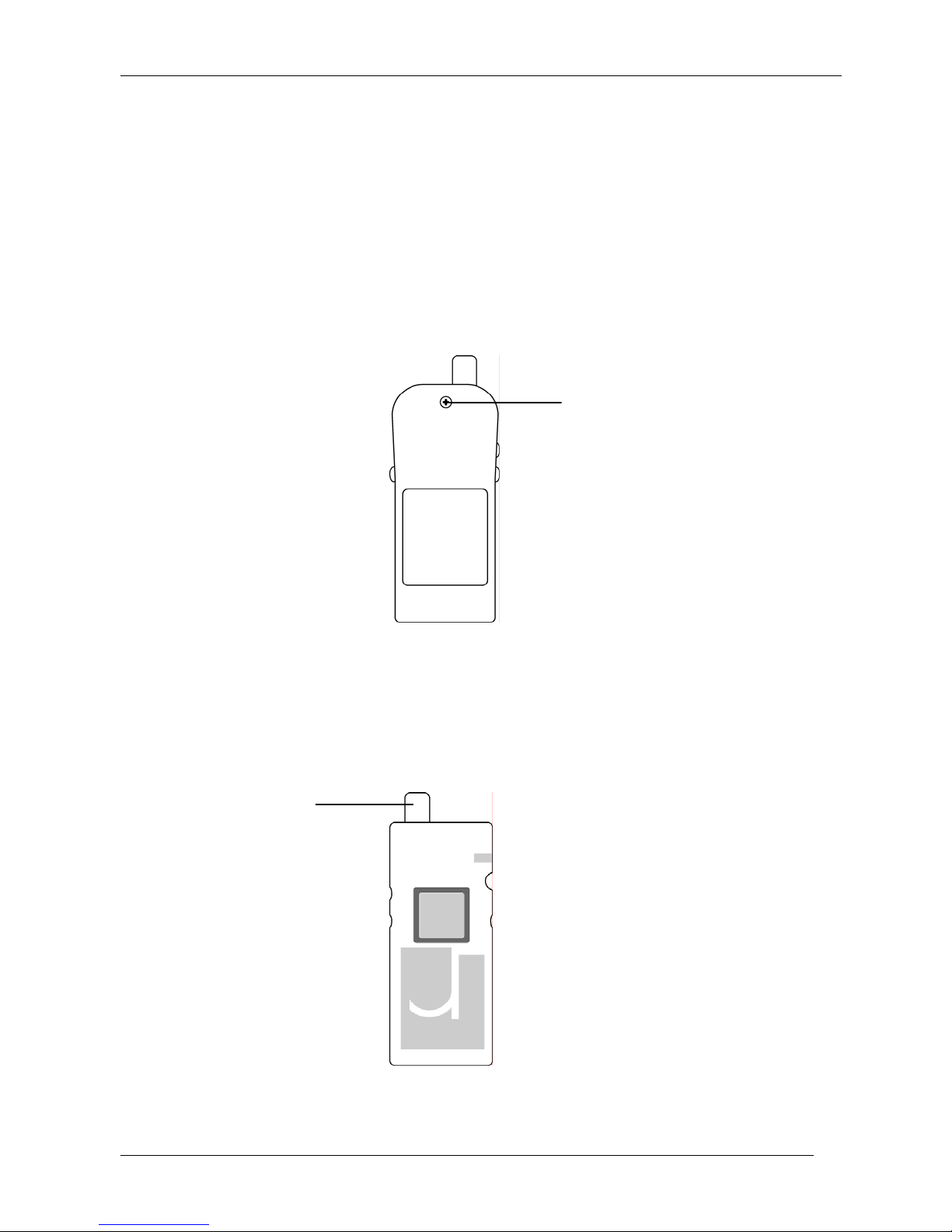
Unscrew the holding screw on the back of the PLD with a Phillips No. 1
2.
screwdriver.
Holding Screw
Figure 2. Back view
While holding the case intact, turn the PLD over and gently remove the front
3.
cover, taking care to pull the front cover free from the bottom tab on the back
cover.
GPS Antenna
Figure 3. PLD with front cover removed (SIM card is not visible from this view.)
6
Page 7
PLD User Guide
With the front cover off, remove the three push buttons and gently lift out the
4.
electronic assembly by supporting the GPS antenna from below, and raising it
upwards. Be careful when disengaging the slider switch from its slot on the
bottom of the case.
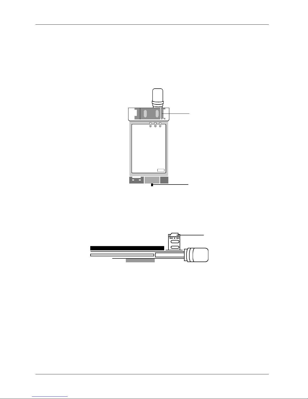
Turn over the electronic assembly and locate the SIM cardholder. Then, move the
5.
slider cover to the open position by sliding it to the right.
SIM Cardholder
Figure 4. Electronic Assembly
Pivot the SIM cardholder outward and insert the SIM card as shown in Figure 5.
6.
Notice the position of the notched corner.
Figure 5. Inserting SIM Card
Pivot the SIM cardholder back into its original position and slide the SIM
7.
cardholder cover to the closed position.
Turn the electronic assembly over and place it into the back cover, with the
8.
battery side facing down. Insert the bottom of the assembly first, to ensure that
the slider switch fits securely into the corresponding slot in the casing.
Slider Switch
SIM Card
Replace the three push buttons and fit the front of the PLD case onto the back
9.
cover, guiding the bottom tab on the back cover into the slot.
Turn the PLD over and insert the holding screw into the back cover.
10.
7
Page 8
PLD User Guide
3. Turning the PLD and LEDs ON/OFF (Slider Switch)
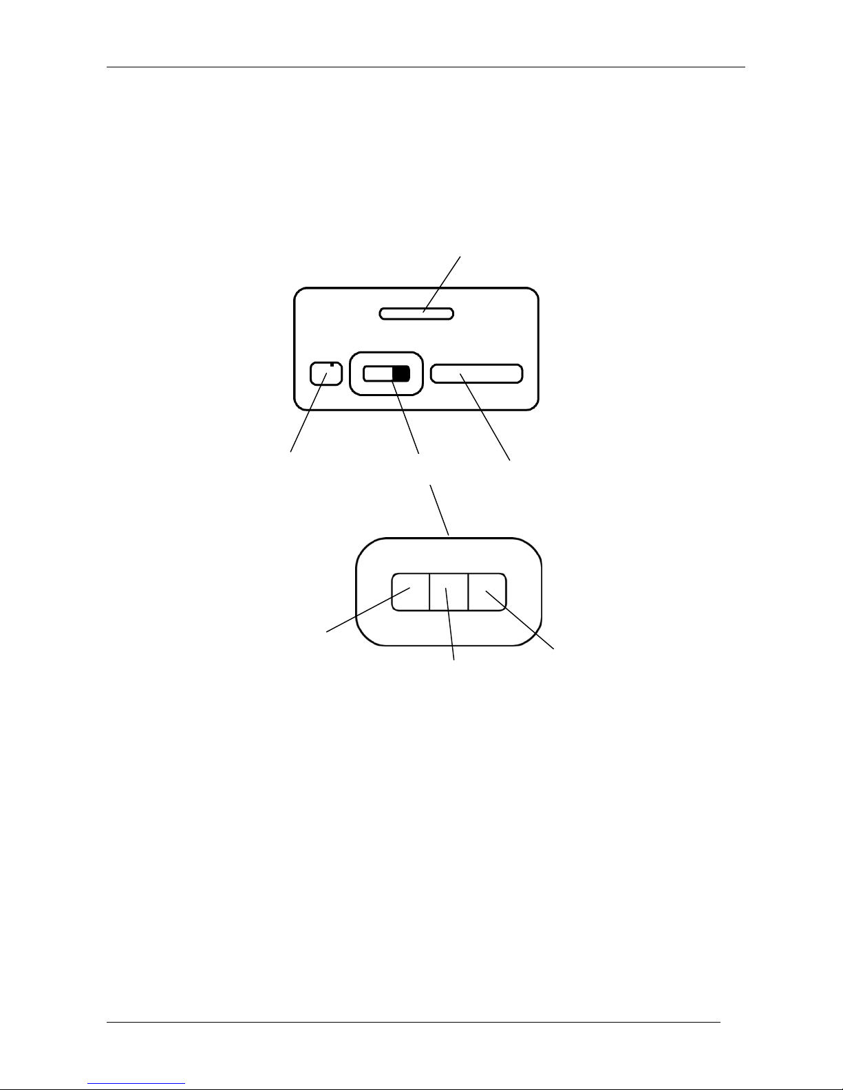
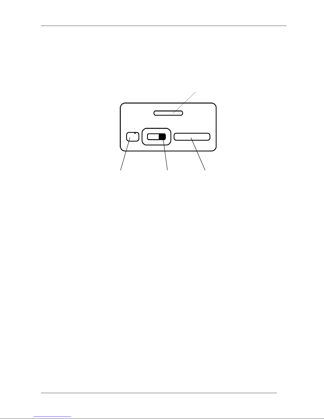
The slider switch is located on the bottom side of the unit. You can slide the switch to
one of three positions to turn the PLD and LEDs ON/OFF. The following diagram
shows the function of each position.
Tab
Charging
Socket
LEFT position:
PLD is ON
LEDs are ON
Slider
Switch
CENTER position:
PLD is ON
LEDs are OFF
Serial Port
RIGHT position:
PLD is OFF
Figure 6. Bottom view and slider switch positions
8
Page 9
4. LED Indicators
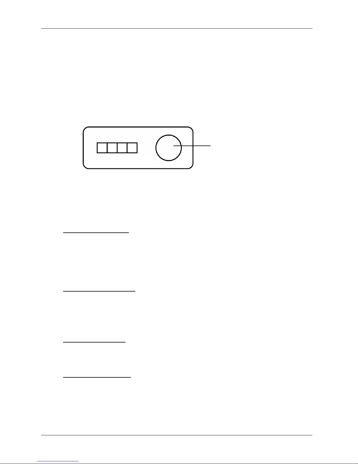
The PLD unit has four Light Emitting Diodes (LEDs). They are:
1. Panic LED (L1)
2. Cellular LED (L2)
3. GPS LED (L3)
4. Power LED (L4)
L1 L2 L3 L4
PLD User Guide
GPS Antenna
Figure 7. Top view showing LEDs and GPS antenna
Panic LED (L1) states
• SOLID GREEN – Unit Charging
• SOLID YELLOW – Unit Charging and Panic Alert Sent
• SOLID RED – Panic Alert Sent
• FLASHING RED – Panic Alert Acknowledged by Command & Control
• OFF – Unit Charged
Cellular LED (L2) states
• SOLID RED – SIM Fail
• FLASHING YELLOW – Network Registered/Roaming/Home
• FLASHING GREEN – Connection Established
• FLASHING RED – Initialization
GPS LED (L3) states
• FLASHING GREEN – Initialization / GPS FIX
• FLASHING YELLOW – No FIX
Power LED (L4) states
• FLASHING GREEN – Initialization / Battery O.K.
• FLASHING YELLOW – Low Battery
9
Page 10
PLD User Guide
5. Troubleshooting and Configuration Using the Serial Por t
The PLD is equipped with a serial port interface that lets you perform troubleshooting
and configuration tasks. When your PC is connected to the PLD via the serial port,
information can be sent to and retrieved from the PLD.
Tab
Charging Socket
Figure 8. Bottom view showing serial port
Slider Switch Serial Port
Plug the PC end of the serial cable into a COM port on your PC.
1.
Plug the PLD end of the cable into the PLD serial port. Note that the cable is
2.
keyed so that it fits into the port in one orientation only. Do NOT force the cable
into the socket.
Turn on the PLD and invoke the PLD Configuration software. The pld config
3.
screen is displayed.
Notice the button Using Com Port x in the upper left corner. Be sure that the
4.
number corresponds with the number of the COM Port you chose in Step 1. To
select a different COM Port, click on the button. You will be prompted for a new
COM Port number.
Be sure that the IP Address and IP Port are set correctly for your tracker. To set
5.
the primary dispatcher IP Address, click on the drop-down menu, select Set
primary dispatcher IP Address, and click on Send Command. To set the
primary dispatcher IP Port, select Set primary dispatcher IP Port, and click on
Send Command. Follow the above steps to set the secondary dispatcher IP
Address and Port.
The GPS and PLD status is constantly displayed line-by-line. If you enter a
6.
command, it will be echoed in this window as well.
10
Page 11

PLD User Guide
You can enter any of the following commands from the drop-down menu:
7.
(VER) – Print FW Version Displays the version of firmware/hardware in
use on the PLD
(INP) – Print Init info (including IMSI, IMEI) Displays initialization details, such as IMSI
number, IMEI number, primary Dispatcher IP
address, secondary Dispatcher IP address and
default Dispatcher
(GPS0) – Stop printing the Gps Message to screen Terminates display of GPS status
(GPS1) – Restart printing Gps message to screen Restarts display of GPS status
(DSP1) – Use primary dispatcher Allows you to select primary MX Dispatcher.
The MX Dispatcher is used to establish
communication with Command & Control.
(DSP2) – Use secondary dispatcher Allows you t o select secondary MX Dispatcher
(DSPx1:xxx.xxx.xxx.xxx) – Set primary dispatcher IP
Address
(DSPx2:xxx.xxx.xxx.xxx) – Set secondary dispatcher
IP Address
(DSPp1:xxxx) – Set primary dispatcher IP port Allows you to set the IP port for the primary MX
(DSPp2:xxxx) – Set secondary dispatcher IP port Allows you to set the IP port for the secondary
(GPS_SW) – Get Gps SW version Displays the version of GPS software in use on
(PNR) – Print Phone Numbers Displays complete list of stored phone
(PN0) – Set phone number 0 - 9 Allows you to store up to 10 phone numbers to
Allows you to set the IP address for the primary
MX Dispatcher
Allows you to set the IP address for the
secondary MX Dispatcher
Dispatcher
MX Dispatcher
the PLD, which could be used for diagnostic
purposes
numbers to be used for voice calls, as
described in Section 6 “Making Voice Calls”
be used for voice calls, as described in Section
6 “Making Voice Calls”
Table 1. List of Troubleshooting and Configuration Commands
11
Page 12
PLD User Guide
6. Making Voice Calls
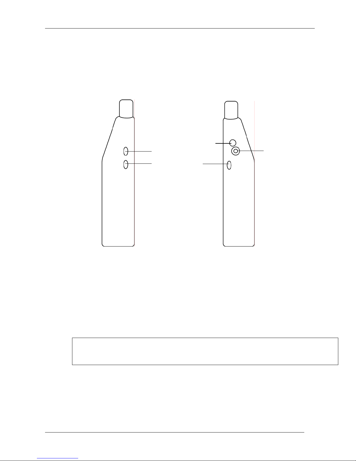
The PLD can automatically dial one of 10 pre-stored telephone numbers that lets you
engage in a voice conversation with someone. You need to plug a standard cellphone
headset into the PLD and depress certain buttons.
External GPS
B1
B2
Antenna Input
B3
Cellphone Headset
Jack (H1)
Figure 9. Side views
Plug a standard cellphone headset into the headset jack (H1).
1.
Press B1 and B3 simultaneously to activate Voicecall. Voicecall automatically
2.
dials a predefined telephone number and lets you conduct a voice conversation
via the headset.
This feature uses phone numbers that are stored on the PLD. See Section 5
“Troubleshooting and Configuration Using the Serial Port” for a description of the
command that allows you to store phone numbers.
12
Page 13
7. Sending a Panic Alert
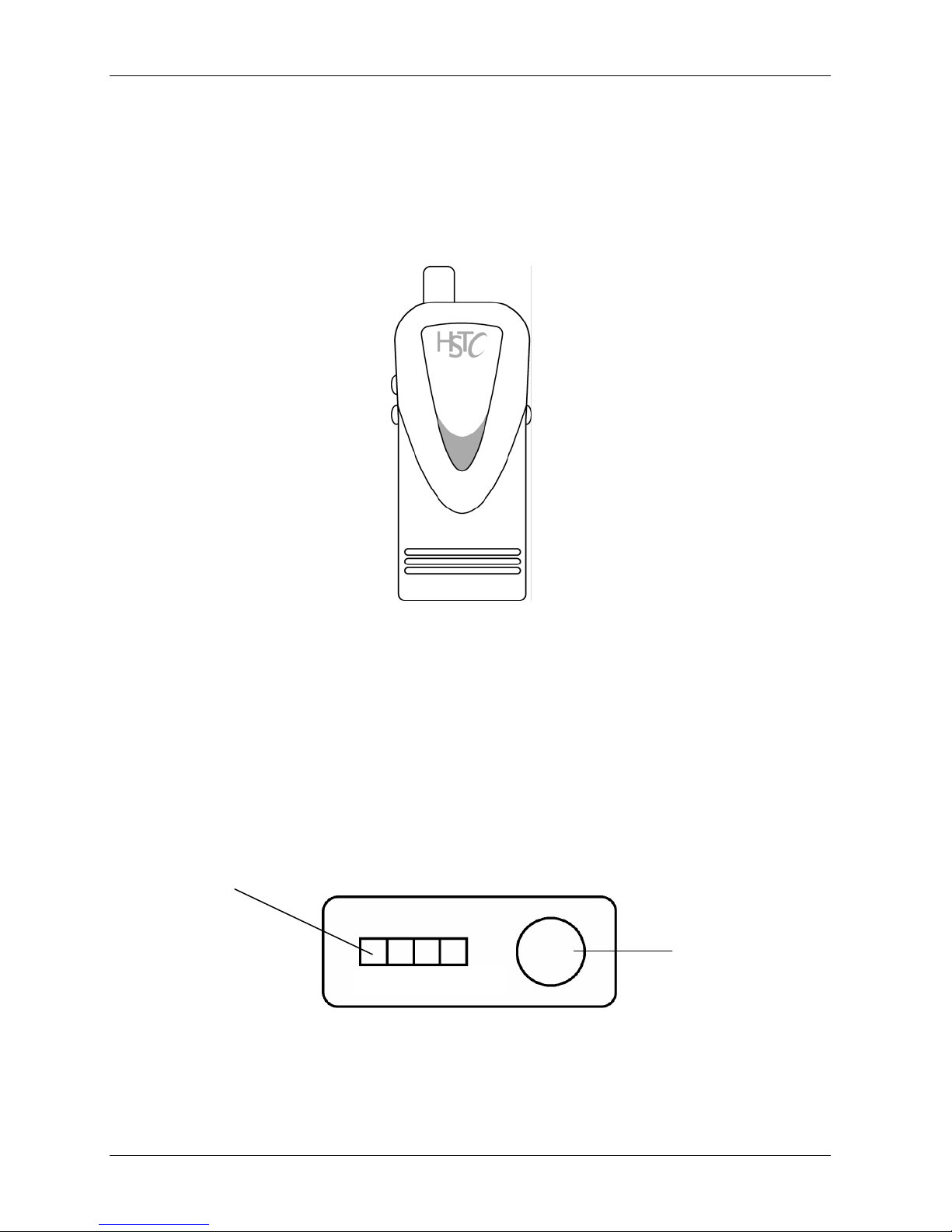
You can request help by pressing certain buttons on the PLD. The PLD then issues a
Panic Alert signal, which is detected by the Command and Control system. The Panic
Alert function uses the PLD’s GPS antenna. Therefore, the PLD unit needs a clear
view of the sky when a Panic Alert message is sent.
B1
B2 B3
PLD User Guide
Figure 10. Push buttons B1, B2, B3
To send a Panic Alert, press B2 and B3 simultaneously.
1.
To confirm that a Panic Alert was sent, check the LED indicators at the top of the
2.
PLD. The L1 LED illuminates solid red or solid yellow when a Panic Alert is sent.
For more information about the LED indicators, see Section 4 LED Indicators.
L1
GPS Antenna
L2 L3 L4
Figure 11. Top view showing LED L1
13
Page 14
PLD User Guide
8. Recharging the Unit
The PLD unit comes equipped with a rechargeable battery. Under typical use, the
battery charge will last for 11 to 12 hours. When the battery charge is low, recharge the
battery using the cable and power adapter provided. A full recharge typically takes
between 3 and 4 hours.
Plug the power adapter into a standard 120V AC socket.
1.
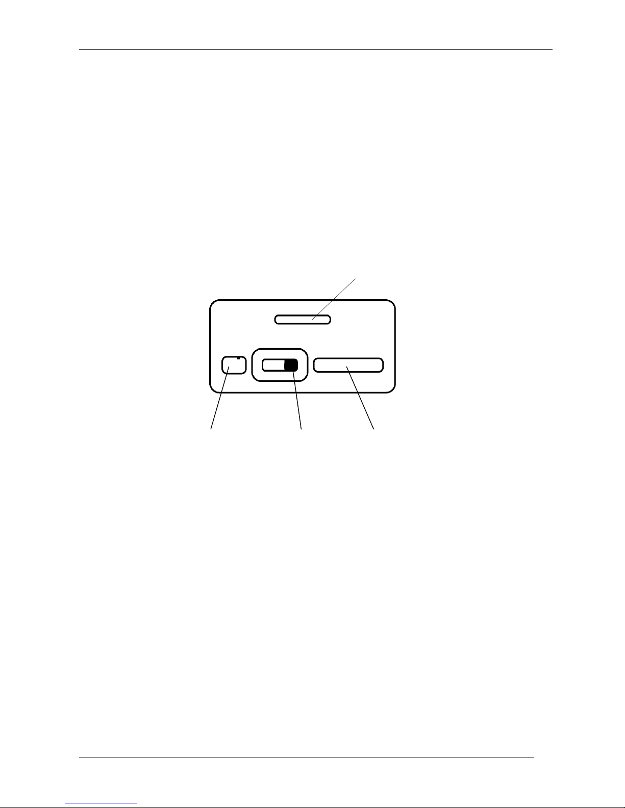
Plug the cable into the charging socket located on the bottom of the unit.
2.
Tab
Charging Socket
Figure 12 Bottom view
Slider Switch Serial Port
We recommend that you slide the switch to the OFF position during charging to
3.
reduce the charging time.
14
Page 15
9. Replacing the Battery
The PLD unit comes equipped with a rechargeable lithium battery. After the normal life
span of the battery has been reached, the battery must be replaced. Obtain
replacement batteries only from HSTC. The part number of the replacement battery is
PL900-073-00. If you insert into the PLD any battery other than the HSTC-approved
replacement, you will void the warranty.
To replace the PLD battery, do the following:
Be sure to ground yourself to discharge your body’s static electricity.
1.
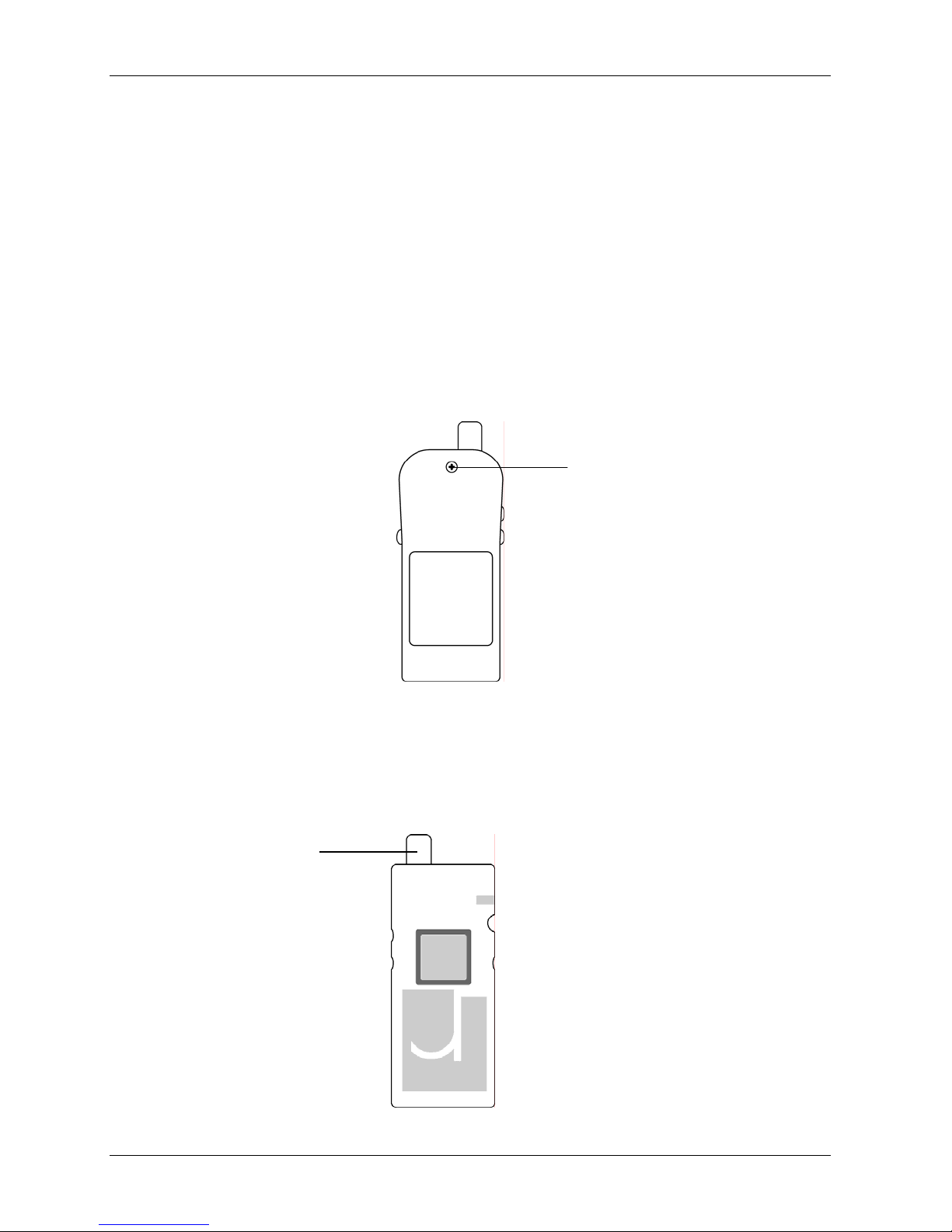
Unscrew the holding screw on the back of the PLD with a Phillips No. 1
2.
screwdriver.
PLD User Guide
Holding Screw
Figure 13. Back view
While holding the case intact, turn the PLD over and gently remove the front
3.
cover, taking care to pull the front cover free from the bottom tab on the back
cover.
GPS Antenna
Figure 14. PLD with front cover removed (Battery is not visible from this view.)
15
Page 16
PLD User Guide
4.
5.
With the front cover off, remove the three push buttons and gently lift out the
electronic assembly by supporting the GPS antenna from below, and raising it
upwards. Be careful when disengaging the slider switch from its slot on the
bottom of the case.
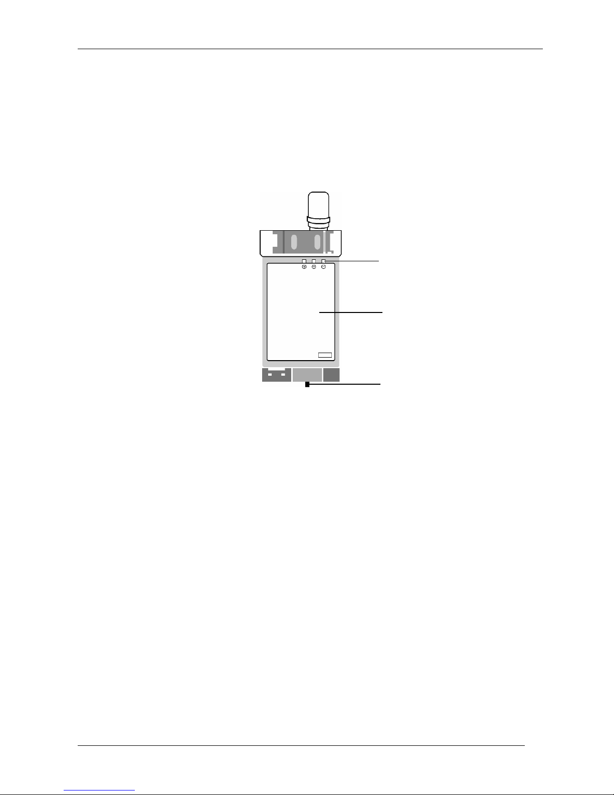
Turn over the electronic assembly and locate the battery.
Battery Contacts
Lithium Battery
Figure 15. Electronic Assembly
Slider Switch
Gently slide the battery towards the spring-loaded contacts, and lift the battery out
6.
from the bottom.
Insert the contact side of the replacement battery first, pressing towards the
7.
spring-loaded contacts. Then press in the bottom of the battery, making sure that
the battery contacts are lined up with the contacts on the holder.
Turn the electronic assembly over and place it into the back cover, with the
8.
battery side facing down. Insert the bottom of the assembly first, to ensure that
the slider switch fits securely into the corresponding slot in the casing.
Replace the three push buttons and fit the front of the PLD case onto the back
9.
cover, guiding the bottom tab on the back cover into the slot.
Turn the PLD over and insert the holding screw into the back cover.
10.
16
Page 17

10. Getting Help
For technical support for your PLD, contact HSTC technical support at:
Telephone: 1-866-798-0905 (toll free) or 905-764-3701
email: mailto:[email protected]
PLD User Guide
17
Page 18

PLD User Guide
Appendix - FCC Information to PLD Users
For Class A Unintentional Radiators:
This equipment has been tested and found to comply with the limits for a Class A digital
device, pursuant to Part 15 of the FCC Rules. These limits are designed to provide
reasonable protection against harmful interference when the equipment is operated in a
commercial environment. This equipment generates, uses, and can radiate radio frequency
energy and, if not installed and used in accordance with the instruction manual, may cause
harmful interference to radio communications. Operation of this equipment in a residential
area is likely to cause harmful interference in which case the user will be required to correct
the interference at his own expense.
Warning: Changes or modifications not expressly approved by Homeland Security
Technology Corporation (Canada) could void the user’s authority to operate the equipment
This device complies with Part 15 of the FCC Rules. Operation is subject to the
following two conditions: (1) this device may not cause harmful interference and (2)
this device must accept any interference received, including interference that may
cause undesired operation.
18
Page 19

PLD User Guide
19
Page 20

PLD User Guide
20
 Loading...