

Page 1

1
- with or without Scandpell
Page 2

2
Contents
1. Included in the delivery .................................................................................................................................................. 3
1.1 Included in the delivery of the TPK with Scandpell .......................................................................................................................3
1.2 Included in the delivery of the TPK without burner ......................................................................................................................4
2. Product summary ........................................................................................................................................................... 5
2.1 TPK with Scandpell ........................................................................................................................................................................5
2.2 TPK ................................................................................................................................................................................................6
2.3 Scandpell wood pellet burner .......................................................................................................................................................7
3. Installation ...................................................................................................................................................................... 8
3.1 Installing the burner: ....................................................................................................................................................................8
3.2 Installation with storage tank (Scandpell) ....................................................................................................................................9
3.2.1 Installation with storage tank type O and separate hot water tank ............................................................................................................. 9
3.3 Installation with domestic hot water tank (Scandpell) ...............................................................................................................11
3.3.1 Installation with pump for domestic hot water priority ............................................................................................................................. 11
3.3.2 Installation with thermostatically controlled domestic hot water production ........................................................................................... 12
3.4 Installation in combination with solar collector system (Scandpell) ...........................................................................................13
3.4.1 Installation with solar storage tank type OS and separate domestic hot water tank ................................................................................. 13
3.4.2 Installation with solar storage tank BS with integrated domestic hot water tank ...................................................................................... 14
3.4.3 Installation with solar hot water storage tank ........................................................................................................................................... 15
3.5 Installing the TPK ........................................................................................................................................................................16
3.5.1 Clearance requirements ............................................................................................................................................................................. 16
3.5.2 Base ............................................................................................................................................................................................................ 16
3.5.3 Flue/chimney ............................................................................................................................................................................................. 17
4. Initial operation – TPK with Scandpell .......................................................................................................................... 18
4.1 Filling the feeder tube .................................................................................................................................................................18
4.2 Test of fuel quantity ....................................................................................................................................................................19
4.3 Starting the Scandpell burner .....................................................................................................................................................19
4.4 Setting of output and combustion air .........................................................................................................................................19
5. Daily use ........................................................................................................................................................................ 20
5.1 TPK with Scandpell ......................................................................................................................................................................20
5.1.1 Operating the control unit ......................................................................................................................................................................... 20
5.1.2 Descriptions of functions ........................................................................................................................................................................... 24
5.2 Maintenance - TPK with and without Scandpell .........................................................................................................................26
5.2.1 Cleaning the heat exchanger ...................................................................................................................................................................... 26
5.2.2 Removing ashes from the boiler ................................................................................................................................................................ 26
5.2.3 Scandpell .................................................................................................................................................................................................... 26
6. Errors ............................................................................................................................................................................ 27
6.1 Alerts ...........................................................................................................................................................................................27
6.2 Failing to ignite ...........................................................................................................................................................................29
7. Product data ................................................................................................................................................................. 31
7.1 Spare parts Scandpell .................................................................................................................................................................31
7.2 TPK Spare parts ...........................................................................................................................................................................32
7.3 Electrical connection ...................................................................................................................................................................34
7.3.1 Scandpell .................................................................................................................................................................................................... 34
7.4 Operating safety Scandpell .........................................................................................................................................................36
7.4.1 Anti-burn-back protection:......................................................................................................................................................................... 36
7.4.2 Protection against loss of combustion air .................................................................................................................................................. 36
7.4.3 Protection against the boiler overheating .................................................................................................................................................. 36
7.3.4 Function check of the safety system .......................................................................................................................................................... 36
7.5 Dimensions, weight and output ..................................................................................................................................................37
7.5.1 Scandpell .................................................................................................................................................................................................... 37
7.5.2 TPK ............................................................................................................................................................................................................. 37
8. EEC declaration of conformity ...................................................................................................................................... 38
9. Test certificate .............................................................................................................................................................. 39
Page 3
3
1. Included in the delivery
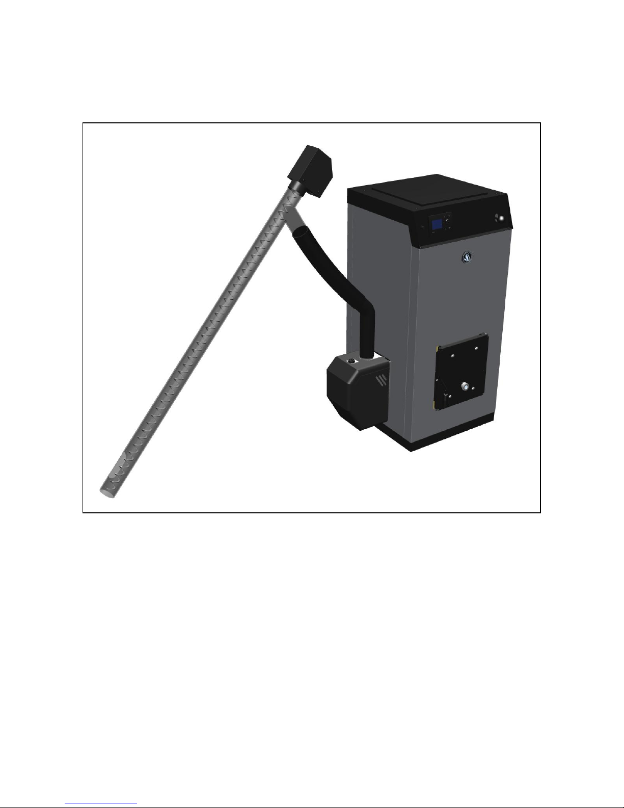
The boiler is available in 2 versions: TPK by itself for installation with another supplier’s pellet burner or
the TPK together with the Scandpell wood pellet burner.
1.1 Included in the delivery of the TPK with Scandpell
Pre-fitted boiler with cabinet
The control unit for the Scandpell is fitted and ready for connection to the burner itself
The boiler is configured for connecting a Scandpell pellet burner on its left or right side – the
opposite side being sealed with an insulated blank
The boiler is fitted as standard with a manually operated cleaning mechanism for the heat
exchanger
The cleaning mechanism is configured for upgrading to fully automatic function. This function is
provided by the control unit
The control unit can either prioritise hot water or heat up a storage tank
Cleaning shovel/ash pan and steel brush
Page 4
4
1.2 Included in the delivery of the TPK without burner
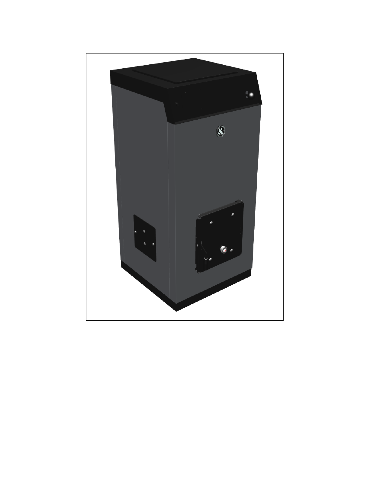
Pre-fitted boiler with casing
The boiler is configured for connecting a pellet burner on its left or right side, or if neither of these
positions can be used, it can be connected via the cleaning access door
The boiler is fitted as standard with a manually operated cleaning mechanism for the exchanger
Cleaning shovel/ash pan and steel brush
Page 5
5
2. Product summary
2.1 TPK with Scandpell
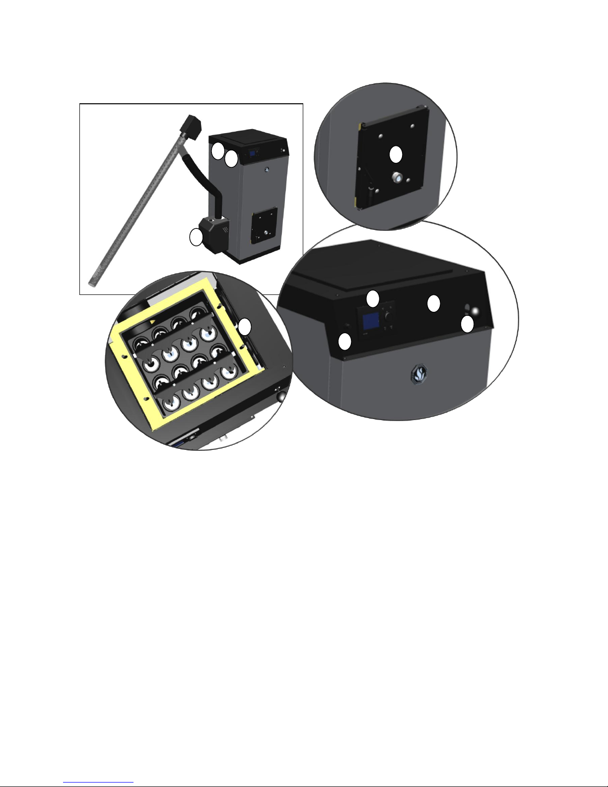
1. Operating panel for Scandpell (this operating panel is used only for this boiler version)
2. Control unit for Scandpell
3. Overheat thermostat
4. Scandpell burner – can be connected to the left or right side. Shown here on the left side
5. Mechanical cleaning system for heat exchanger
6. Cleaning access door with inspection window
7. Filling air vent
8. Connector for attaching pressure gauge
1 2 3 5 6 4 5 7 8
Page 6
6
2.2 TPK
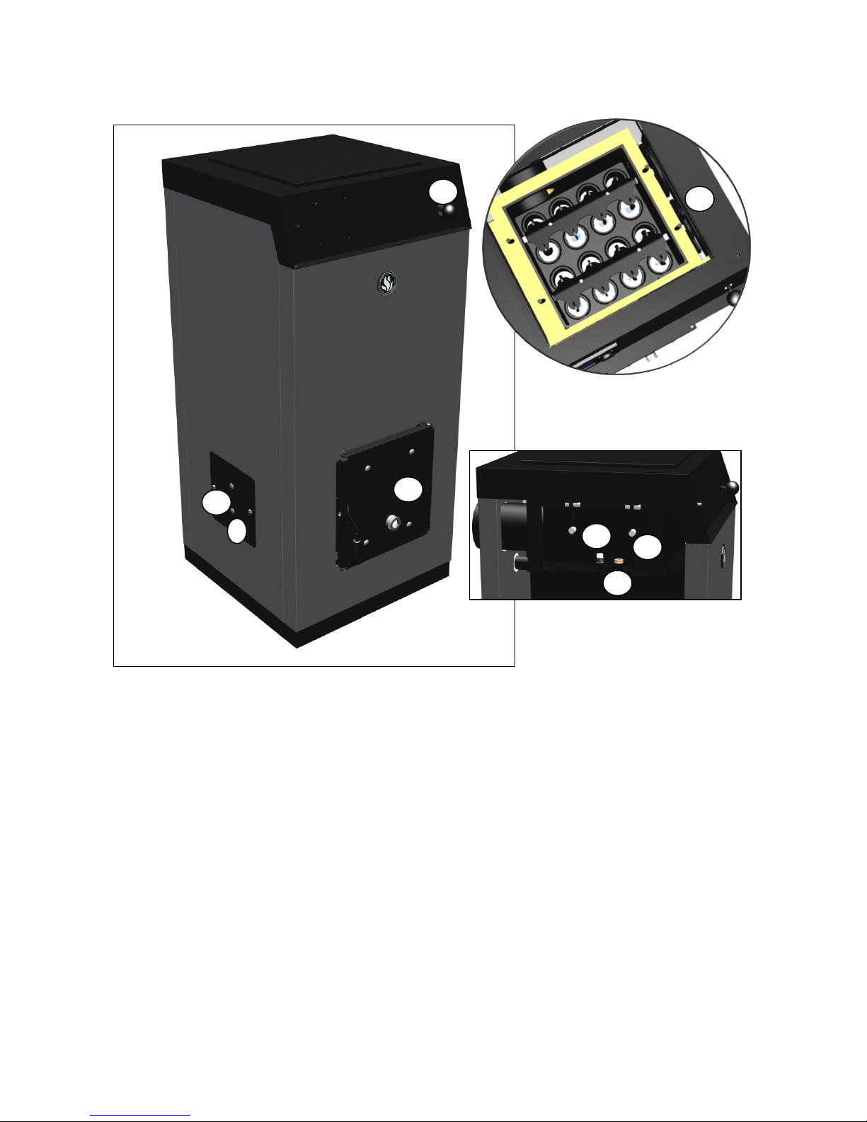
9. Blank on both sides (fitted when delivered without Scandpell)
10. Pellet burner can be connected on either left or right side
11. Mechanical cleaning system for heat exchanger
12. Cleaning access door with inspection window – can be used to connect burners that cannot be
connected to left or right side.
13. Sensor housing
14. Manual air vent
15. Connector for attaching optional pressure gauge
9
11
11
12
13
14
15
10
Page 7
7
2.3 Scandpell wood pellet burner
The TPK with Scandpell is delivered with the burner ready for use.
It is simply a matter of placing the burner on the desired side of the boiler and plugging it into the control
unit.
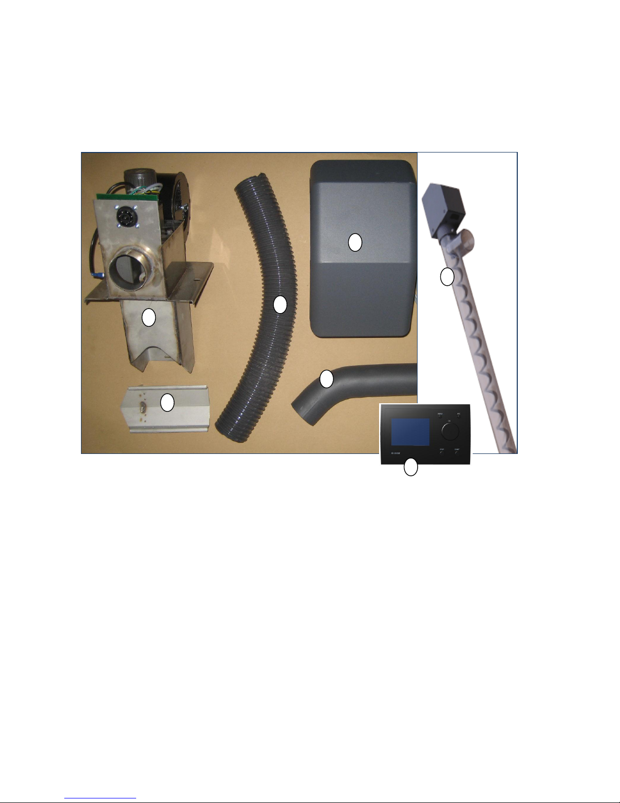
The burner consists of the following components:
1. Burner head with pre-fitted fan, distribution circuit board, stoker motor, igniter, light sensor and
max. temperature thermostat.
2. Burner plate
3. Rigid downpipe
4. Flexible downpipe
5. Burner cover
6. Feed pipe (1,7 metre) with feeder motor
7. Control unit
The control unit is pre-fitted to the boiler at delivery and all plug-in connectors are ready for connecting to
the burner.
The boiler sensor is placed in the boiler’s sensor housing and the overheat thermostat is connected.
1 2 3 4 5 6 7
Page 8
8
3. Installation
3.1 Installing the burner:
TPK with Scandpell:
The Scandpell can be installed on the right or left side of the TPK.
The boiler is completely symmetrical based around the combustion chamber and the 2 coupling connector
holes for connecting the Scandpell burner.
The burner is connected via one hole, and the coupling connector with an insulated blank is fitted in the
other hole.
TPK:
It is not certain that a burner other than a Scandpell can be installed using either of the holes in the side of
the boiler.
It may instead be necessary to install the burner via the front cleaning access door.
This cleaning access door is not pre-prepared for installation of this kind, and it may require specific
adaptation for the burner in question.
The distance from the front of the boiler to its back wall is 515 mm. This distance must be
sufficient for the wood pellet burner used in order to ensure that it works properly.
The inclination of the feeder tube must not exceed an angle of 45 ° from horizontal.
If not, it cannot be assured that sufficient fuel is brought to the burner.
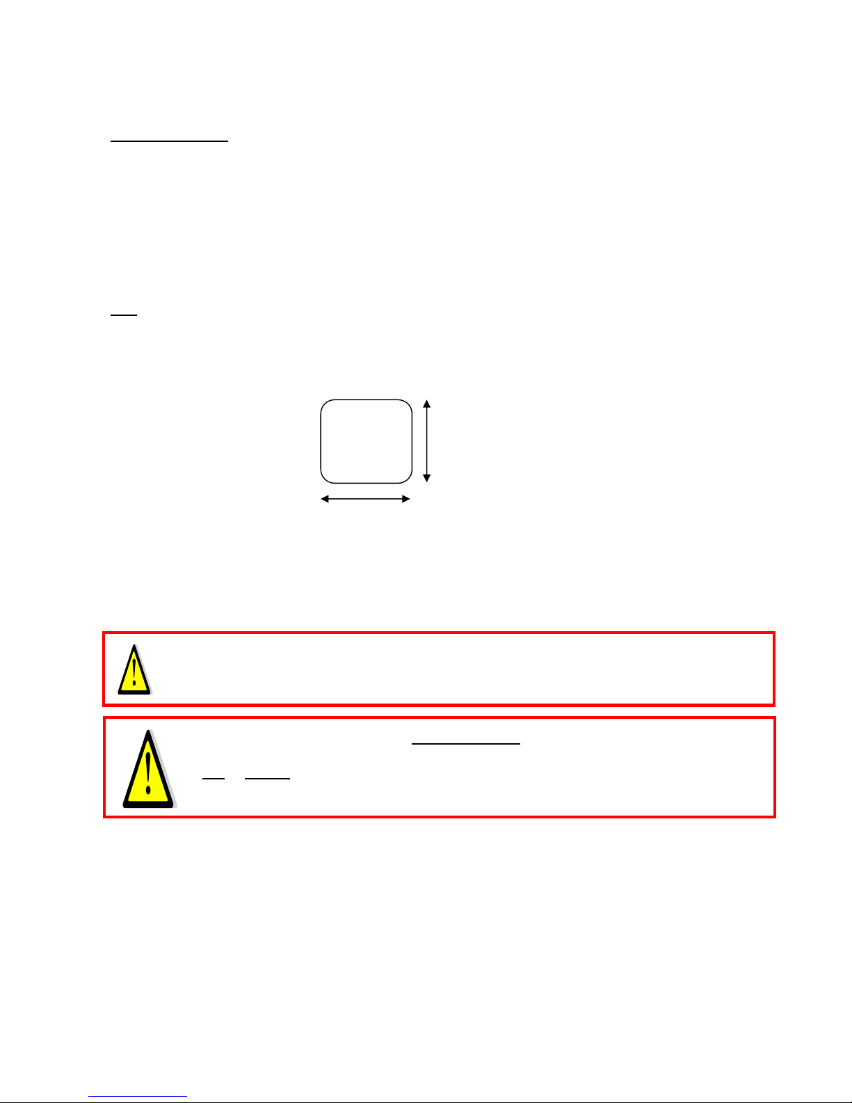
120 mm
120 mm
Page 9
9
3.2 Installation with storage tank (Scandpell)
The boiler can be installed with either a storage tank or a hot water tank, if the control unit is to control
one of these.
In other words, it is not possible to set up a system with both a storage tank and a hot water
tank controlled by the control unit.
The boiler’s additional temperature sensor is located in a sensor pocket in the storage tank – usually in the
middle part of the tank.
In order to avoid corrosion in the boiler, a device must be installed that ensures a minimum
return temperature of 55 °C to the boiler.
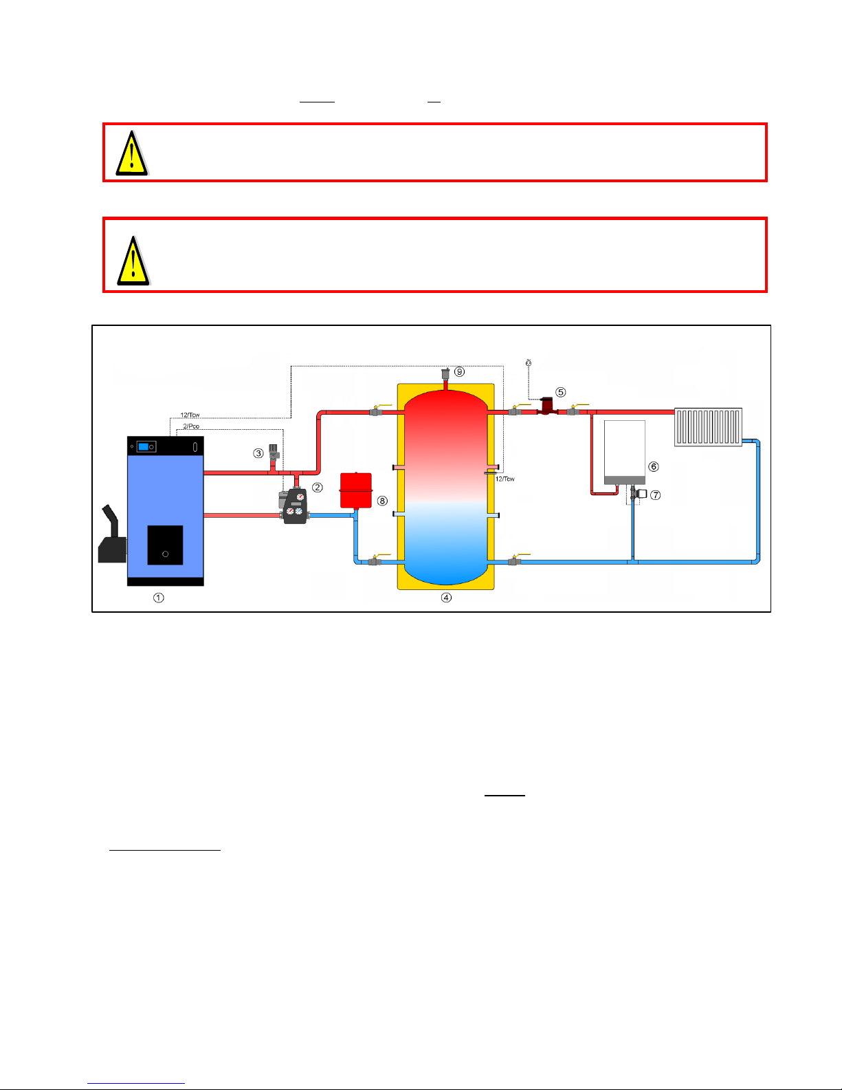
3.2.1 Installation with storage tank type O and separate hot water tank
1: TPK/Scandpell
2: Loading Unit 55 °C (you could also use a thermostatic 3-way valve and pump – (use a balancing valve on the shunt loop)
3: Safety valve
4: Storage tank type O (800, 1000 or 1500 liter)
5: Heating circuit pump
6: Hot water tank VBF 85, VBF 100 or VBF 150
7: Thermostat with external sensor bulb
8: Expansion tank (the size should be adapted to the total volume of the system)
9: Automatic air vent
Please note that on this installation the summer/winter function cannot be used. To be set to winter
(standard set up).
Control unit set up:
Function of extra sensor is set to the storage tank (Service menu).
Pump function: Boiler pump (Service menu)
Set the desired storage tank temperature (storage tank menu in User’s menu)
Storage tank minimum temperature is set at the same place by setting the hysteresis at a suitable value.
See also the functional description in 5.1.2.
Page 10
10
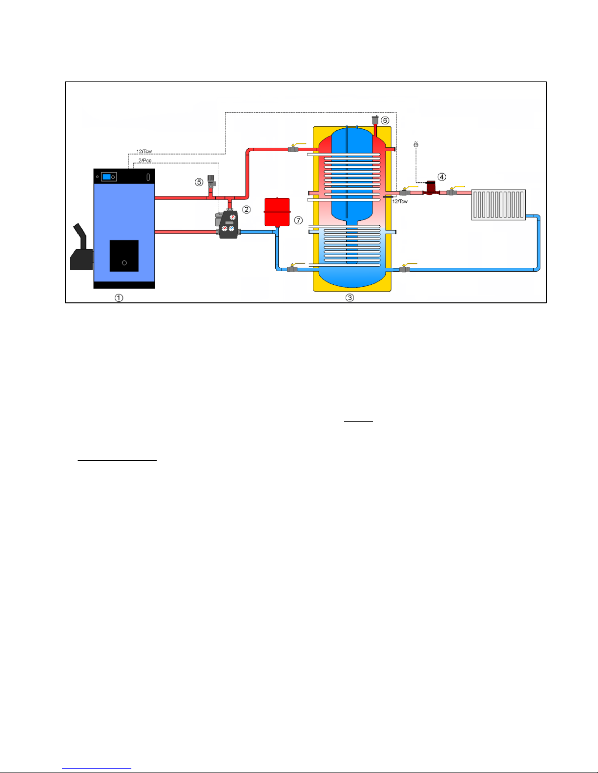
3.2.2 Installation with storage tank BS with integrated domestic hot water tank.
1: TPK/Scandpell
2: Loading Unit 55 °C (you could also use a thermostatic 3-way valve and pump – (use a balancing valve on the shunt loop)
5: Safety valve
3: Storage tank type BS (800, 1000 or 1500 liter)
4: Heating circuit pump
6: Automatic air vent
7: Expansion tank (the size should be adapted to the total volume of the system)
Please note that on this installation the summer/winter function cannot be used. To be set to winter
(standard set up).
Control unit set up:
Function of extra sensor is set to the storage tank (Service menu).
Pump function: Boiler pump (Service menu)
Set the desired storage tank temperature (storage tank menu in User’s menu)
Storage tank minimum temperature is set at the same place by setting the hysteresis at a suitable value.
See also the functional description in 5.1.2.
Page 11
11
3.3 Installation with domestic hot water tank (Scandpell)
The boiler can be installed with either a storage tank or a domestic hot water tank, if the control unit is to
control one of these.
In other words, it is not possible to set up a system with both a storage tank and a hot water
tank controlled by the control unit.
In order to avoid corrosion in the boiler, a device must be installed that ensures a minimum
return temperature of 55 °C to the boiler from the unit.
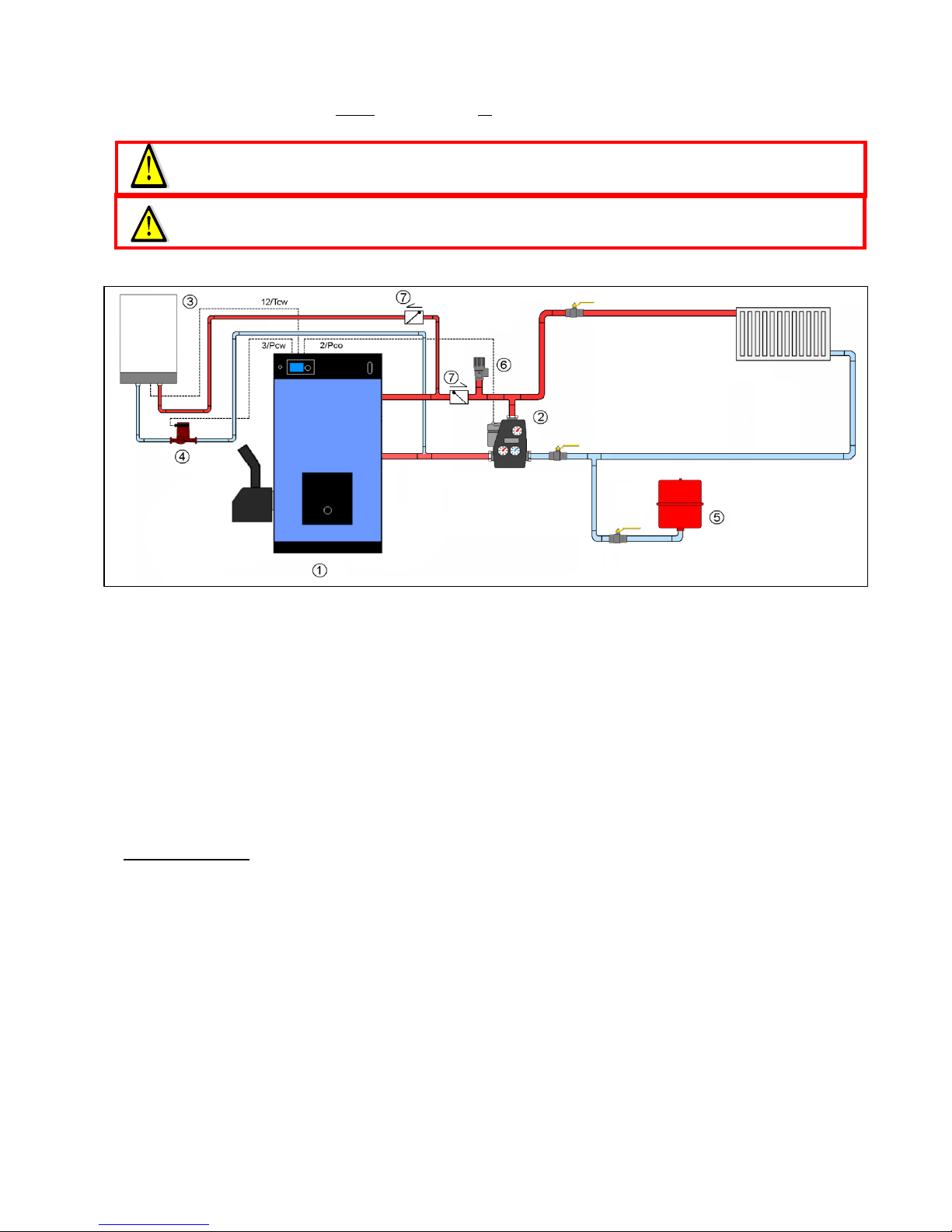
3.3.1 Installation with pump for domestic hot water priority
1: TPK/Scandpell
2: Loading Unit 55 °C (you could also use a thermostatic 3-way valve and pump – use a balancing valve on the shunt loop.
3: Hot water tank VBF 85, VBF 100 or VBF 150
4: Domestic hot water priority pump
5: Expansion tank (the size should be adapted to the total volume of the system)
6: Safety valve
7: Non return valve
If it is decided that the control unit’s hot water facility is to be used, it is important that the non return
valve is installed, as shown in the diagram. The summer/winter function could easily be used with this kind
of installation (Boiler parameters in User’s manual): In case this function is desired it is set to summer
function.
Control unit set up:
Function of extra sensor is set to the domestic hot water (Service menu).
Pump function: Boiler pump (Service menu)
Set the desired hot water temperature (storage tank menu in User’s menu)
Minimum temperature is set at the same place by setting the hysteresis at a suitable value.
You can either choose between absolute or divided priority (domestic hot water in Hot water menu in
User’s menu).
See also the functional description in 5.1.2.
Page 12
12
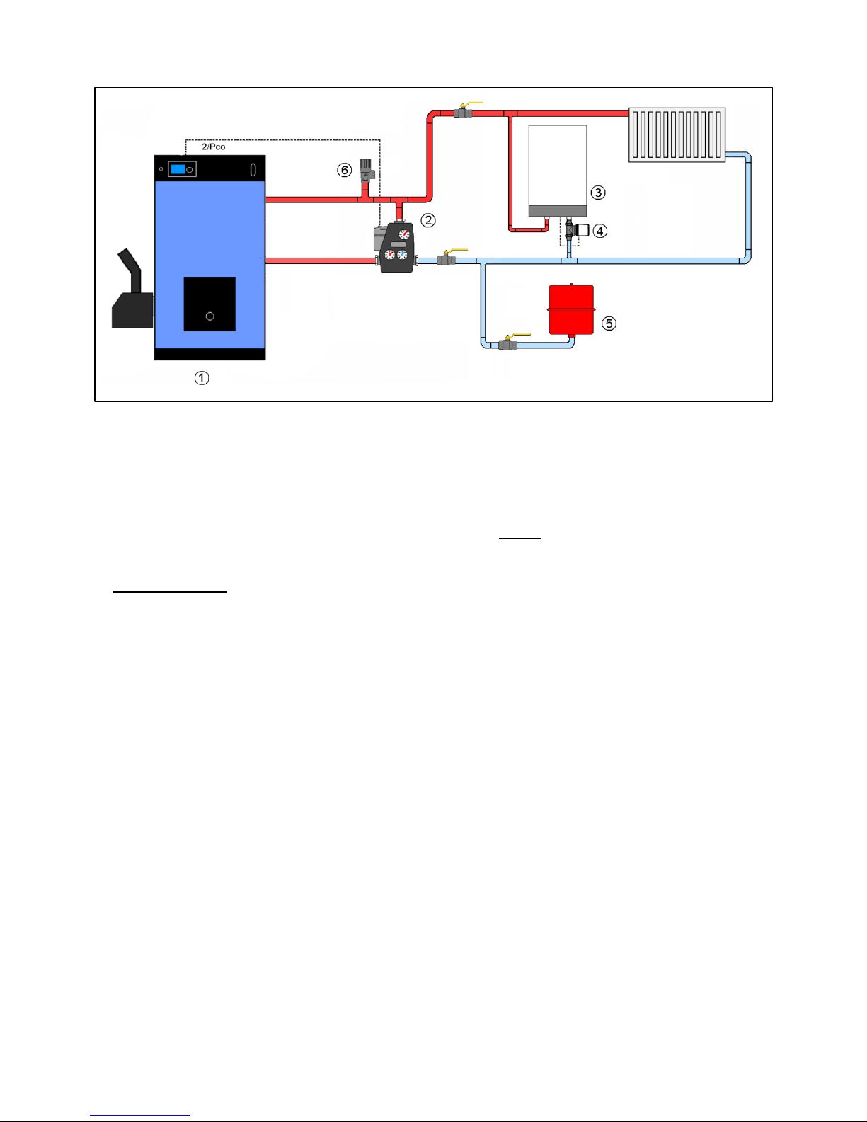
3.3.2 Installation with thermostatically controlled domestic hot water production
1: TPK/Scandpell
2: Loading unit 55 °C (you could also use a thermostatic 3-way valve and pump – use a balancing valve on the shunt loop
3: Hot water tank VBF 85, VBF 100 or VBF 150
4: Thermostat with external sensor bulb
5: Expansion tank (the size should be adapted to the total volume of the system)
6: Safety valve
Please note that on this installation the summer/winter function cannot be used. To be set to winter
(standard set up).
Control unit set up:
Function of extra sensor is set to OFF (”Service menu”)
Pump function: Boiler pump (”Service menu”)
The boiler temperature is set by turning the rotary button
See also the functional description in 5.1.2.
Page 13
13
3.4 Installation in combination with solar collector system (Scandpell)
If the boiler is to be installed in combination with a solar collector system, it is important to
take the return pipe from the storage tank at such a height that the part of the storage tank
where the solar collector element is located is not heated up by the boiler.
Below installation examples are based on the use of solar collector systems from HS Tarm. If using other
solar collector systems the examples might not be useable. Please check the function options for the solar
collector systems of other manufacturers before deciding the final installation.
In order to avoid corrosion in the boiler, a device must be installed that ensures a minimum
return temperature of 55 °C to the boiler from the unit.
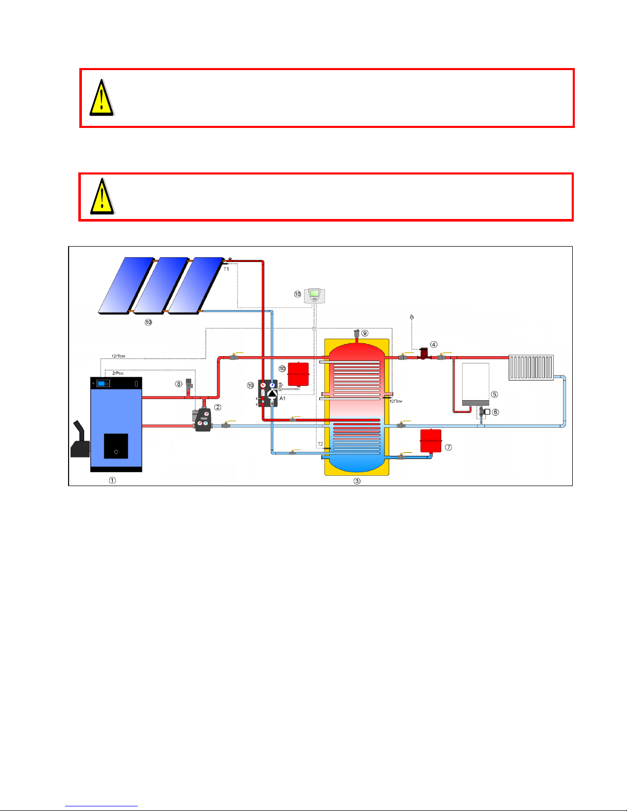
3.4.1 Installation with solar storage tank type OS and separate domestic hot water tank
1: TPK/Scandpell
2: Loading unit 55 °C (you could also use a thermostatic 3-way valve and pump – use a balancing valve on the shunt loop.
3: Storage tank type OS (800, 1000 or 1500 liter)
4: Heating circuit pump
5: Hot water tank VBF 85, VBF 100 or VBF 150
6: Thermostat with external sensor bulb
7: Expansion tank (the size should be adapted to the total volume of the system)
8: Safety valve
9: Automatic air vent
10: Solar collector system - Solar package C
The boiler and the solar collector system jointly heat the storage tank.
The central heating runs independently of the boiler and solar collector system.
In cases where the solar collector system generates so much energy that the storage tank is at risk of
overheating. It is important that there is always some kind of idle consumption in the system, e.g. heat leak
radiator in the bath room.
Control unit set up – see 3.2: Solar collector control unit set up – see manual for Solar package C.
See also the functional description in 5.1.2.
Page 14
14
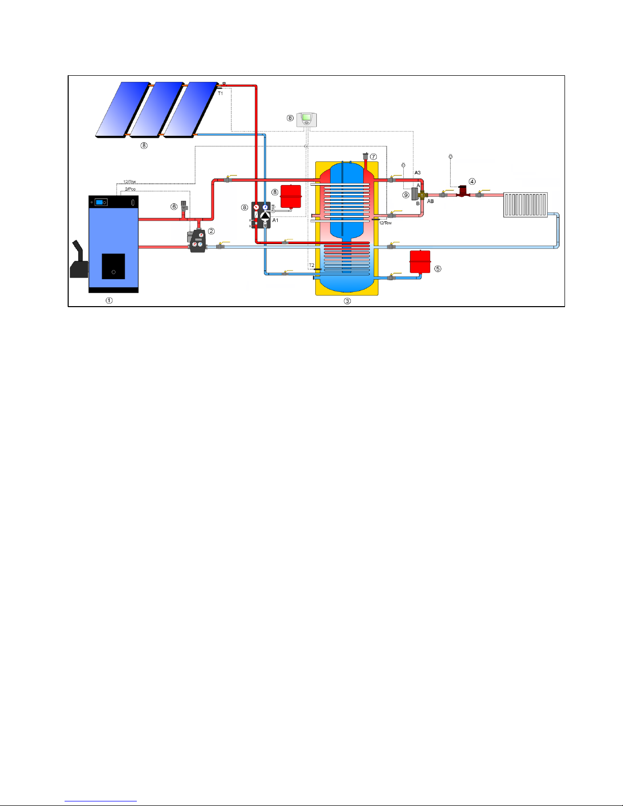
3.4.2 Installation with solar storage tank BS with integrated domestic hot water tank
1: TPK/Scandpell
2: Loading unit 55 °C (you could also use a thermostatic 3-way valve and pump – use a balancing valve on the shunt loop
3: Storage tank type BS (800, 1000 or 1500 liter)
4: Heating circuit pump
5: Expansion tank (the size should be adapted to the total volume of the system)
6: Safety valve
7: Automatic air vent
8: Solar collector system – Solar package C
9: 3-way zone valve
The boiler and the solar collector system jointly heat the storage tank.
The system side runs independently of the boiler and solar collector system. In cases of over production of
energy from solar collector system, the 3-way zone valve shifts from the normal flow from the storage tank
to the top of the storage tank.
In cases where the solar collector system generates so much energy that the storage tank is at risk of
overheating, it is important that there is always some kind of idle consumption in the system, e.g. heat leak
radiator in the bath room.
Set up of control unit (Scandpell) – see 3.2
Set up of solar collector system control unit – see manual for Solar package C
See also functional description in 5.1.2.
Page 15
15
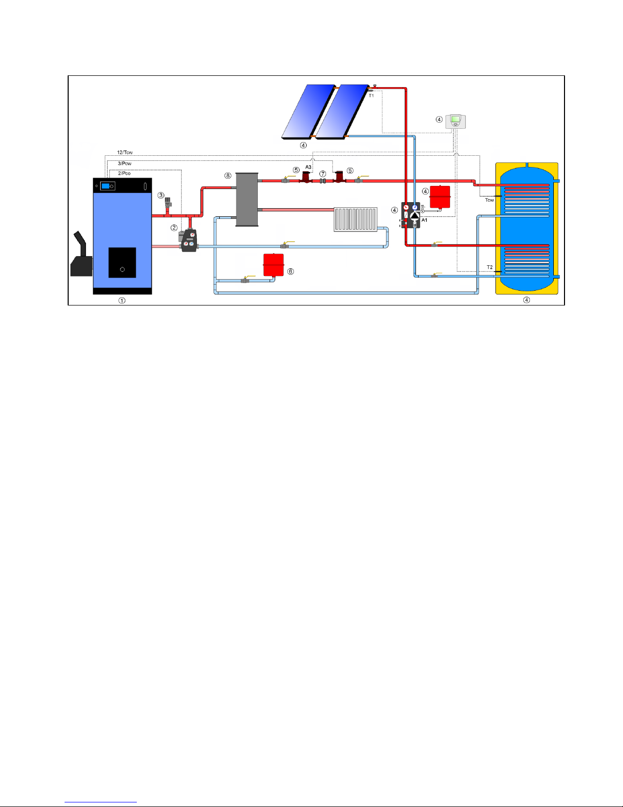
3.4.3 Installation with solar hot water storage tank
1: TPK/Scandpell
2: Loading unit 55 °C (you could also use a thermostatic 3-way valve and pump – use a balancing valve on the shunt loop)
3: Safety valve
4: Solar collector system Solar package A or B
5: Pumps (removal of excess heat and auxiliary heating respectively)
6: Expansion tank (the size should be adapted to the total volume of the system)
7: Double flow restrainer (spring loaded) – prevents gravity circulation
8: Hydraulic separator
The solar collector system is the primary domestic hot water production system. The boiler supplies
auxiliary heating if need be.
Excess heat is removed from the domestic hot water storage tank when the energy production from the
solar collector system is so much that the temperature in the storage tank exceeds the set maximum limit.
Set up of control unit (Scandpell) – see 3.3.1 (summer-/winter function however, not useable.
Solar collector control unit set up - see manual for solar package A or B.
See also the functional description in 5.1.2.
Page 16
16
3.5 Installing the TPK
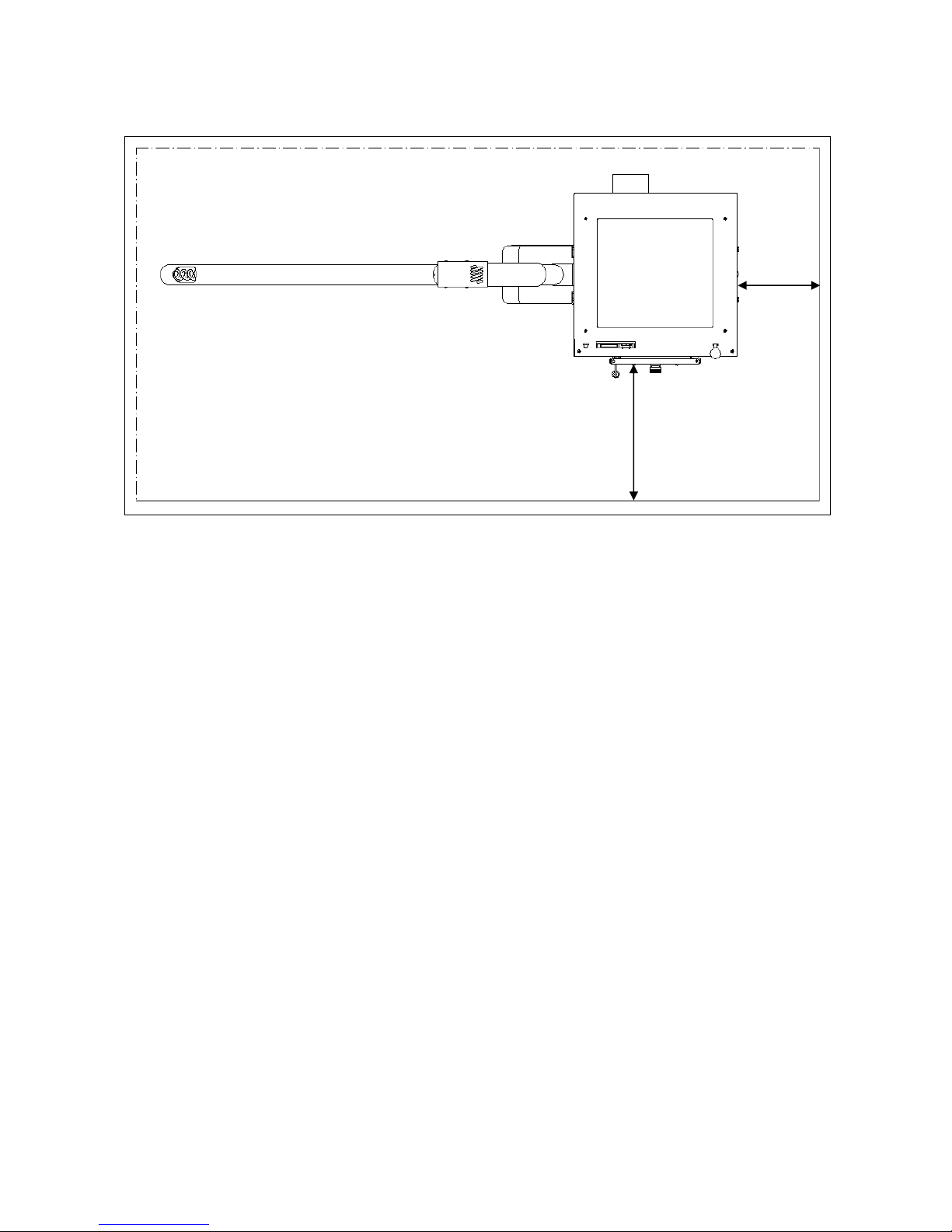
3.5.1 Clearance requirements
According to Danish regulations, there must be a minimum distance of 0.5 meters from anything flammable
in front of the boiler (see UK building regulations).
There must be a minimum distance of 0.3 meters from anything flammable to the side of the boiler
opposite the burner.
Behind the boiler, the applicable requirement for clearance between the flue and any flammable materials
is decisive. This means that, according to Danish regulations, there must be a minimum distance of 0.3
metres from the surfaces of not insulated flues to flammable materials. If manufactured, insulated pipes
with approved clearances are to be used there must be compliance with these clearances.
3.5.2 Base
The boiler must be placed on a dry, level and non-flammable base.
The base must be non-flammable to at least 0.5 meters in front of the boiler.
Note that it may be advisable to place the boiler on a platform so that it is raised above floor level. This will
facilitate cleaning of the area around the boiler.
0,5 meter
0,3 meter
Page 17
17
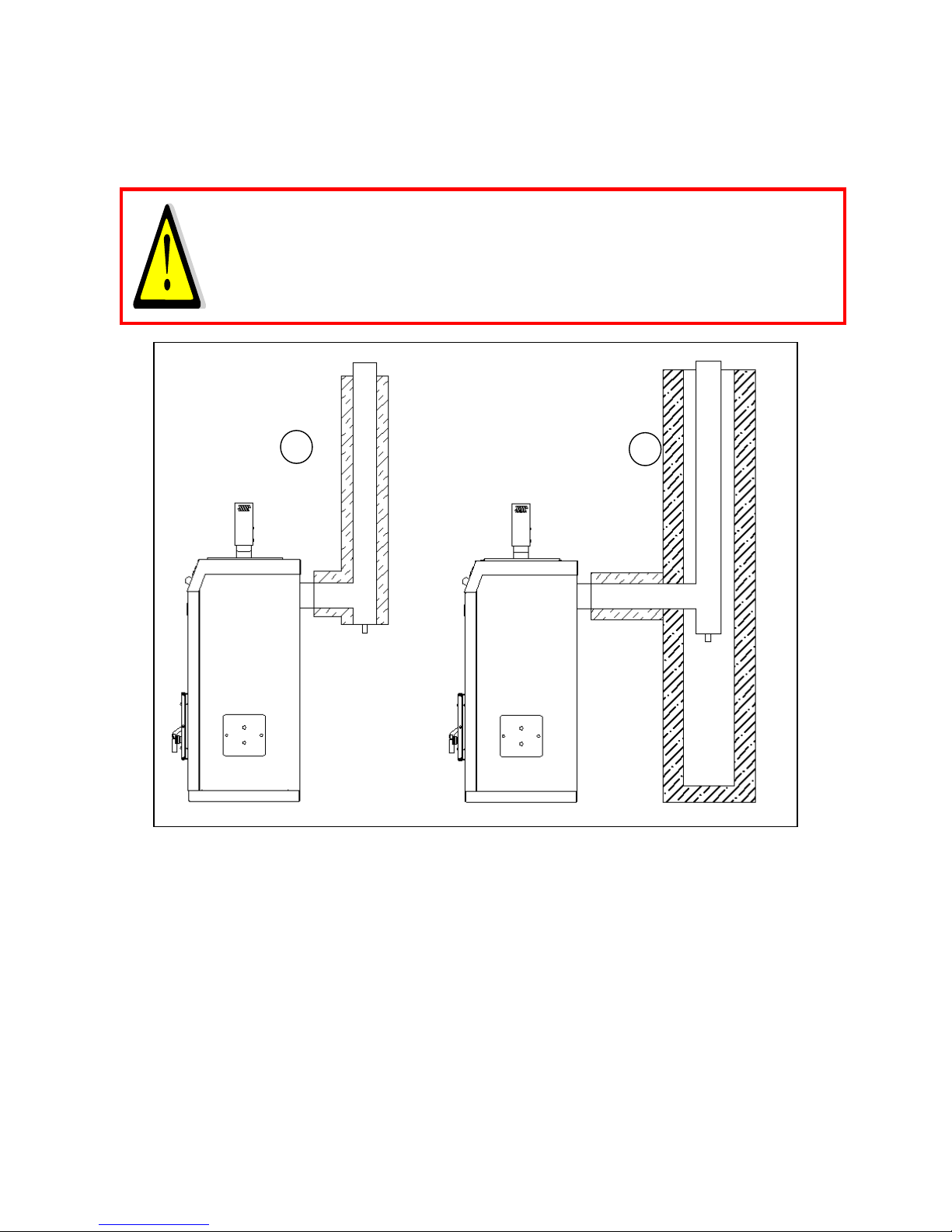
3.5.3 Flue/chimney
3.5.3.1 TPK and Scandpell
The temperature of the flue gas, especially at low output, may result in the formation of condensation in
the flue/chimney.
It is therefore recommended that a flue is used which is appropriate in wet conditions.
Always install the flue from the flue gas outlet from the boiler in such a way as to prevent
condensation from the chimney running back into the boiler.
Always use a draft stabilizer.
1: installation with an insulated steel flue
2: Installation with a flue fitted into an existing chimney
In both cases, a condensate drain must be fitted in the bottom of the vertical section of the flue, and the
part of the flue between the boiler and the vertical section should be insulated.
Necessary minimum chimney draft: 0.1 mbar
3.5.3.2 TPK with a burner from another supplier
When installing a burner other than a Scandpell, the same precautions should usually be taken as when
using a Scandpell.
The flue gas temperature is determined primarily by the boiler. The requirements in terms of the flue can
be deviated from only where a wood pellet burner is used that can only run constantly at high output.
The required minimum chimney draft is dependent on the burner being used.
1
2
Page 18
18
4. Initial operation – TPK with Scandpell
Once the system has been set up and connected to the mains (see the wiring diagrams under 7.2), the fuel
container must then be filled with fuel.
4.1 Filling the feeder tube
The time taken to fill the feeder tube with fuel is dependent on a number of factors. This is affected by both
the diameter and length of the wood pellets, and the angle of the feeder tube also has a considerable
influence on this.
The inclination of the feeder tube must not exceed an angle of 45 ° from horizontal.
If not, it cannot be assured that sufficient fuel is brought to the burner.
The operating time for the feeder motor during filling of the feeder tube can be adjusted in the ”Service
Menu”:
1. Press the ”Menu” button at least 3 seconds – the display then changes to ”Service Menu”
2. Use the rotary control to highlight the menu point ”Feeder auger”
3. Press the rotary control to select this menu point.
4. Press the rotary control once more to adjust the run time for the feeder motor during filling of the
feeder tube.
5. If you wish to change the time, rotate the rotary control unit until the required time is displayed.
6. Press the rotary control to confirm the selected value.
The default factory setting is 3 minutes, which in most cases is less than the required value. It is important
however not to select a run time that is considerably longer than is necessary.
When the feeder motor is started up for the first time, it can only be stopped by
disconnecting the control unit from the mains power supply.
If the feeder tube is filled with so much fuel that the surplus material ends up in the
downpipe and the burner, this extra material must be removed before starting up the burner.
You should therefore start out with a setting of 3 minutes. The other option is to disconnect the downpipe
from the burner and place a bucket beneath the outlet during filling.
To start filling the feeder tube, do the following:
1. Press shortly ”Menu” button on the control unit
2. Use the rotary control to highlight the menu point ”Feeder auger filling”
3. Press the rotary control to select this menu point
4. Move the rotary control marker to ”YES” and press the rotary control
A forced running of the feeder motor is started, which will then begin to feed the feeder tube with fuel.
The feeder motor will stop again after the first 3 minutes. You can see in the transparent feeder tube how
far the filling process has got. If filling is not complete, repeat the process and adjust the run time if
necessary before the next run.
Page 19
19
4.2 Test of fuel quantity
The quantity of fuel should be tested before the burner it put into operation.
The quantity of fuel for firing has a standard been set to 15 seconds.
This time should give between 75 to 100 g fuels in the combustion chamber.
Loosen the feed pipe from the burner and let it end in a bucket or similar.
Go into ”Service Menu” (press more than 3 seconds on the menu button); Chose the subject ”Test of
outputs”; chose ”Feeder auger”.
Press the rotary control and take time; after 15 seconds press the rotary control again.
The fuel quantity that has ended in the bucket should be weighed.
The quantity should be between 75 – 100 g fuels. If not a run time should be found that gives a quantity
within this range. Repeat the process until the correct time has been found.
Having found the sufficient time the value is adjusted under menu ”Pellet quantity” in menu ”Ignition” in
”User’s Menu” (press shortly the Menu button) to the time found.
4.3 Starting the Scandpell burner
The Scandpell burner is easy to start up by pressing the ”START” button on the front of the control unit.
Press and hold down for more than 3 seconds.
Remember that the feeder tube must be filled with wood pellets before the burner is started.
It might be necessary to adjust the correct quantity for firing.
4.4 Setting of output and combustion air
Outputs and correct quantity of combustion air depend on the fuel used.
Therefore always measure CO and O2 emissions from the flue gases.
Correct set quantity of air at both output levels should give between 10 – 12 % O2 in the flue
gases.
Begin with default; adjust the air quantity at high and low output respectively until the measured O2 values
are within the mentioned interval.
Pellet quality – above all the quantity of sawdust – might have a great influence on the transport of fuel
from the hopper to the burner. The more sawdust in the fuel the less fuel can be brought to the burner
each time unit. In general it would be seen that the maximum output decreases at an increasing content of
sawdust in the fuel. The content of fuel will also require that the minimum output is set in comparison with
default in order to avoid unstable operation.
Much sawdust in the fuel will often lead to failed ignitions after a short operational time. It is
important to let the hopper run empty more often is there is much sawdust in the fuel. When
the hopper is empty it shall be checked for piled sawdust – this should be removed before
further fuel is filled into the hopper.
Page 20
20
5. Daily use
5.1 TPK with Scandpell
5.1.1 Operating the control unit
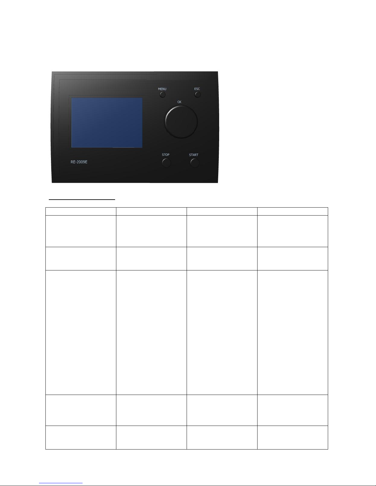
Functions of the buttons:
Button
Function 1
Function 2
Explanation
MENU
Pressing this button
briefly changes the
display to the user menu
Pressing for longer than
3 seconds changes the
display to the ”Service
menu
-
ESC
Press this button to go
back one level in the
menu
-
E.g. you can use ESC to
exit a sub-menu.
OK
The rotary control also
has a press function. To
change a value, press
this button to select the
parameter
Turn this button to
select parameters in
menus.
Turn the button to
change a value –
clockwise to increase
the value and counter
clockwise to reduce the
value.
When the display is
shown, rotate the
button and you can
either set the boiler
temperature, or if the
storage tank function is
chosen you can set the
storage tank temperature.
STOP
Pressing this button for
more than 3 seconds
stops the burner.
Receipt for error
messages
Function 2: Corrected
errors are set back by
pressing the STOP
button.
START
Pressing this button for
more than 3 seconds
starts the burner.
-
-
Page 21
21
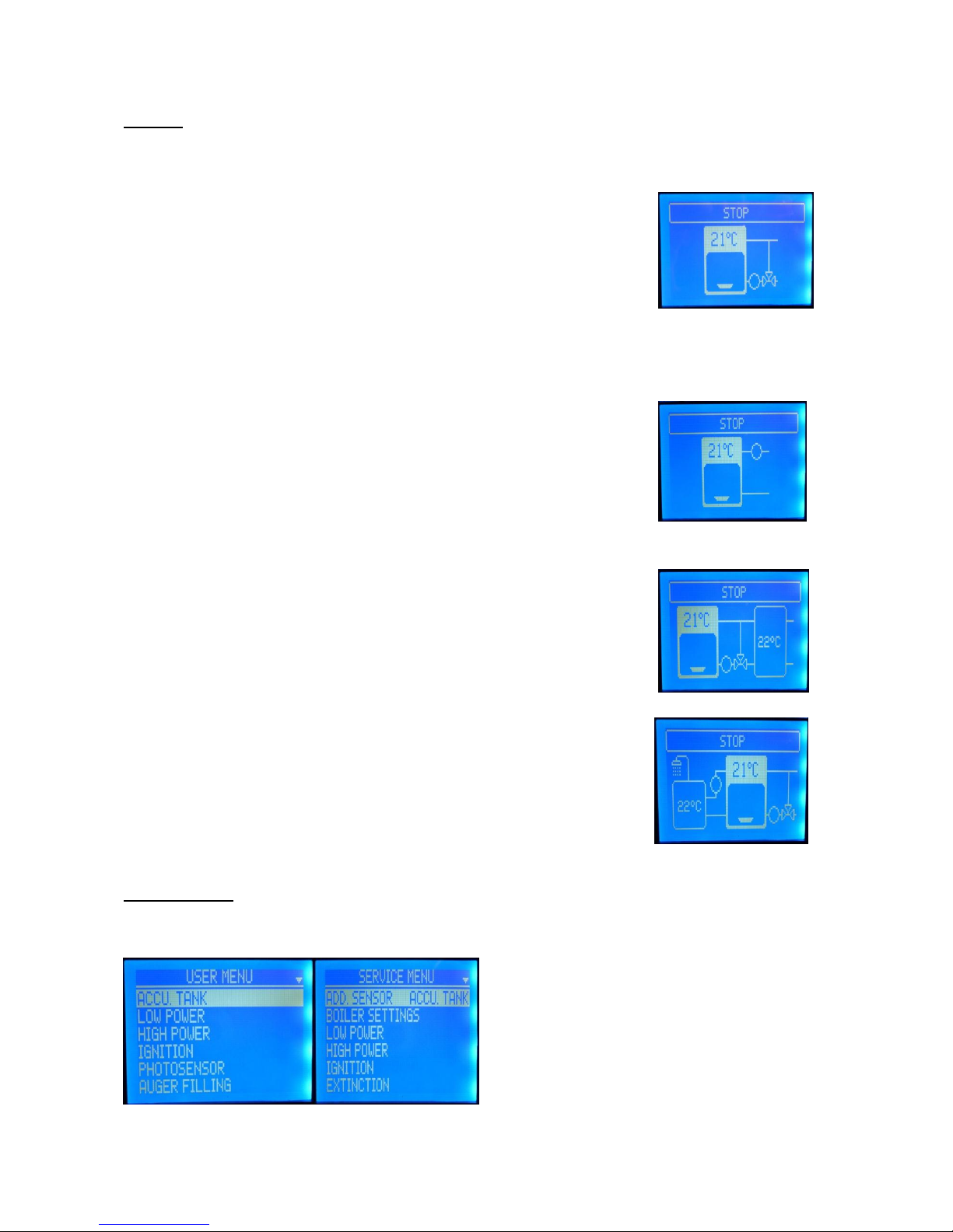
Displays:
Display when neither hot water nor storage tank function is activated and
the pump is activated as boiler pump.
Display when neither hot water nor storage tank function is
activated and the pump is activated as heating pump.
Display when storage tank function is activated:
Display when hot water tank function is activated:
Menu functions:
Pressing the MENU button provides access to the USER and SERVICE MENUS:
Page 22

22
User menu:
User menu
Text
Default
values
Min. value
Max. value
Explanation
Boiler parameters 1)
Set point temp.
65 °C
E.g. 65 °C 2)
E.g. 85 °C 2)
Desired boiler
temperature
Summer/winter
Winter
Winter
Summer
If summer is selected
the heating circuit
pump stops
Storage tank 3)
Set point temp.
70 °C
40 °C
80 °C
Desired storage tank
temperature
Hysteresis
15 °C
1 °C
30 °C
Temperature less than
storage tank set point
at which heating starts
Hot water 3)
Hot water priority
No
No
Yes
Set to Yes gives
absolute priority for hot
water (heating circuit
pump stops when hot
water pump starts)
Legionella function
OFF
OFF
ON
-
Set point temp.
60 °C
30 °C
70 °C
Set point for the
temperature in the hot
water tank
Hysteresis
10 °C
1 °C
10 °C
Hot water pump
hysteresis
Low output
Fan level
22 %
1 %
100 %
Fan speed at low
output
Pellet volume
30 %
1 %
60 %
Operating time for
feeder motor at low
output
High output
Fan level
30 %
1 %
100 %
Fan speed at high
output
Pellet volume
60 %
1 %
60 %
Operating time for
feeder motor at high
output
Ignition
Fan level
30 % 4)
1 %
100 %
Fan speed at ignition
Pellet volume
15 sec
1 sec
60 sec
Operating time for
feeder motor at ignition
Light sensor
Current light strength
--
0
1023
Current light value
(cannot be set)
Minimum light strength 5)
10
0
1023
Min. light value for fire
in the fuel
Feeder auger filling
Do you want to start filling
the feeder auger?
Yes
No
Used for force-filling
the feeder-auger, e.g.
at start-up following a
dry run.
Time set
Time and date set
--
- - Set time and date
1) when selecting the extra sensor as storage tank sensor the set possibility of the boiler temperature disappears.
2) depends on the setting under ”SERVICE MENU”
3) either the storage tank or hot water menu point is displayed depending on the selection made under the ”Service menu”.
4) 30 % for burners with a blank fan; burners with black fan have a default value of 3% when the ignitor is mounted in a pipe of the
same length as the ignitor and 15% when the ignitor is placed in a long pipe.
5) the normal setting may vary; check the value (current light strength) when the light sensor is not working (take out the light
sensor and cover it if need be); the minimum light strength is set 5 to 8 points higher than the value in darkness.
Typical screen shots when setting values and changing setup:
Page 23

23
”Service menu”:
”Service menu”
Text
Default
values
Min. value
Max.
value
Explanation
Extra sensor
OFF, hot water, storage tank
OFF - -
Selection of function for extra
temperature sensor
Extra pump function
Circ. pump, boiler pump
Boilerpump
- - Selection of function for pump
Boiler parameters
Min. temperature
65 °C
40 °C
78 °C
Min. set point for boiler temperature
Max. temperature 1)
85 °C
78 °C
94 °C
Set point for temperature in hot water
tank
Overheat
95 °C
86 °C
99 °C
Max. boiler temperature – higher temp.
sets off an alarm
Hysteresis
10 °C
1 °C
20 °C
Necessary fall in boiler temperature
before re-start is possible.
Circuit pump *)
Start pump
52 °C
40 °C
70 °C
Boiler temperature at which the boiler
temperature should start
Hysteresis
2 °C
1 °C
10 °C
Number of degrees less than pump start
temperature at which pump should stop
Cyclic
No
No
Yes
The pump can either operate
continuously or cyclic.
Switching frequency **)
5 min
1 min
240 min
Time when pump is either ON or OFF
Low output
Fan delay
15 sec
1 sec
200 sec
Delay in fan speed change when switching
to low output.
Hysteresis
5 °C
1 °C
20 °C
Number of degrees less than the set point
at which a change-over to low load occurs
with increasing boiler temperature
High output
Fan delay
15 sec
1 sec
200 sec
Delay in change of fan speed at change to
high output.
Hysteresis
10 °C
1 °C
20 °C
Number of degrees less than the set point
at which a change-over to high load
occurs with decreasing boiler
temperature
Ignition
Max. ignition time
6 min
1 min
30 min
Time-out in case of ignition attempts
Max. number of attempts
2 1 10
Max. number of extra ignition attempts
Cleaning time
30 sec
1 sec
200 sec
Pre-ventilation of burner before start of
ignition
Burn out
Burn out time
15 sec
1 sec
900 sec
Fan run time after shut down
Burner auger
Burner auger
ON
ON
OFF
-
Run time at stop
20 sec
1 sec
200 sec
Required time for removing fuel out of
the internal auger
Pause
3 sec
2 sec
200 sec
Pause internal auger
Cycle
2 sec
1 sec
3 sec
Run time internal auger
Feeder auger
Filling time
3 min
0 min
30 min
Required time for filling the feeder auger
Light sensor
Measurement frequency
1 Hz
1 Hz
10 Hz
Measurement frequency for light sensor
Hysteresis
15 0 99
Required increase above minimum of light
value before ignition stops after start.
Cleaning
Cleaning
OFF
ON
OFF
Only to be ON if automatic cleaning
system is available.
Cooling time
60 sec
1 sec
200 sec
Pre-ventilation of burner before cleaning
starts
Opening time
3 min
1 min
20 min
Cleaning time
Quantity of burnt out material
5 0 100
Number of shut downs between cleanings
On min
0 h
0 h
4 h
Shortest time in hours between cleanings
On max
4 h
4 h
100 h
Longest time between cleanings
Not earlier than
07.00
00.00
Latest
Cleaning must not take place before this
hour
Latest
21.00
Not earlier
than
24.00
Cleaning must not take place after this
hour
Default settings
Back to factory settings.
-
Yes
No
-
Test outputs
2) - - - -
Test inputs
3) - - - -
Language
Language
Danish
Polish,
English,
German
and Danish
-
1) Operation with storage tank: The max. temperature decides when the burner stops if the boiler gets hotter than the storage tanks.
2) and 3): see next page
*) only active when circuit pump is selected; **) only active when ”cyclic” is set to Yes.
Page 24

24
Test outputs:
Test element (output)
Default
Press OK and change to:
Fan
OFF
ON
Boiler pump
OFF
ON
Hot water pump
OFF
ON
Feeder auger
OFF
ON
Burner auger
OFF
ON
Ignition element
OFF
ON
Cleaning
OFF
ON
Pressing OK again toggles between OFF and ON
Test inputs:
Test element (input)
Current value (example values)
Boiler sensor
50 °C
Light sensor
157
Hot water sensor
48 °C
Fan circuit
ON
Auger circuit
ON
Thermal fuse (burner head)
ON
External control (external start/stop input)
ON
This menu only displays current values – it is not possible to make any changes.
5.1.2 Descriptions of functions
5.1.2.1 Installation directly to the heating system
As long as there is a heat take-off from the boiler that is greater than the minimum output and less than
the maximum output, the burner will shift between the 2 output levels, so that the boiler temperature is
less than the set point for the boiler temperature (under ”Boiler parameters” in the User menu). The
average temperature in the boiler is controlled by the high and low output hysteresis respectively.
The shift between high and low outputs can be adjusted by using the hysteresis for each of the output
levels.
The default hysteresis is 5 °C for low output and 10 °C for high output (under ”Low output” and ”High
output” respectively in the ”Service menu”):
When the boiler temperature is increasing, the burner will change over from high to low output
when the boiler temperature is 5 °C less than the set point for the boiler temperature.
When the boiler temperature is falling, the burner will change over from low to high output when
the boiler temperature is 10 °C less than the set point for the boiler temperature.
If the heat take-off from the boiler becomes less than the low output, the boiler temperature will increase
until the set point for the boiler temperature is reached, at which point the burner will stop.
The burner will not re-start until the boiler temperature is less than the set point for the boiler temperature
minus the hysteresis (under ”Boiler parameters” in the ”Service menu”).
The default value is 10 °C
If e.g. the set point for the boiler temperature is 70 °C, the boiler will not re-start until the boiler
temperature has fallen below 60 °C after the burner has been stopped.
Page 25
25
5.1.2.2 Installation with storage tank
If this type of installation is selected, it is the temperature in the storage tank that determines when the
burner starts up, and when the burner is in standby.
The storage tank functions in principle as an extension of the boiler volume. When the storage tank sensor
(extra sensor has been selected to function as a storage tank sensor – under “Extra sensor” in the ”Service
menu”) measures a temperature that is less than the end set point for the boiler temperature minus the
storage tank hysteresis (under the User menu if the storage tank function is selected in the ”Service menu”)
the burner starts.
Example:
The set point for the boiler temperature has been set to: 70 °C
The hysteresis for the storage tank has been set to: 15 °C
The Scandpell unit starts up when the temperature in the storage tank (measured by extra sensor) reaches
(70-15) = 55 °C
The Scandpell stops again once the boiler temperature has reached 70 °C.
Depending on how low down in the storage tank the return line to the boiler is located, and where the
extra sensor in the storage tank is located, the entire storage tank will be heated through – and therefore
the same temperature as the boiler. This requires sufficient flow in the system, so that all the energy
produced in the boiler is transferred to the storage tank – otherwise the burner stops when max. boiler
temperature is reached.
The pump must be set to be boiler pump and operate as long as the burner will not be in standby
or manually stopped. Thus the pump stops when the burner is in standby.
With the storage tank the set point for the boiler temperature is decided by the set value for max.
boiler temperature: Factory setting = 85 °C and the hysteresis is 10 °C.
5.1.2.3 Installation with a hot water tank
If it is decided to use the external sensor as a temperature sensor in a hot water tank, the control unit will
be able to start and stop a filling pump for the tank.
This filling pump starts up once the temperature measured by the extra sensor that is located in the tank
measures a temperature that is lower than the set point temperature minus the hot water hysteresis (Set
point temperature and hysteresis can be found in ”User Menu” under ”Hot water”).
Example:
Set point temperature: 55 °C
Hysteresis: 5 °C
The pump starts up when the temperature in the tank is lower than 50 °C and stops again when the
temperature in the tank is over 55 °C.
Page 26
26
5.2 Maintenance - TPK with and without Scandpell
5.2.1 Cleaning the heat exchanger
The boiler is fitted as standard with a manual mechanical system for cleaning the heat exchanger. The
handle on the front of the boiler is used to move the turbulators in the heat exchanger up and down, and in
this way removing ashes and soot. The loosened material falls down into the combustion chamber.
5.2.2 Removing ashes from the boiler
Ashes from the burner and from cleaning out the heat exchanger fall into the bottom of the combustion
chamber. They are then removed from here manually – using the supplied shovel for example.
The intervals between cleaning out the bottom of the combustion chamber are dependent on the rate at
which wood pellets are burned. As there is space for quite a lot of ash in the boiler, it is rarely necessary to
clean them out more than once a month.
5.2.3 Scandpell
The frequency of necessary cleaning will vary depending on the quality of the wood pellets, and the type of
burner and settings used.
However, an interval of less than 14 days is recommended.
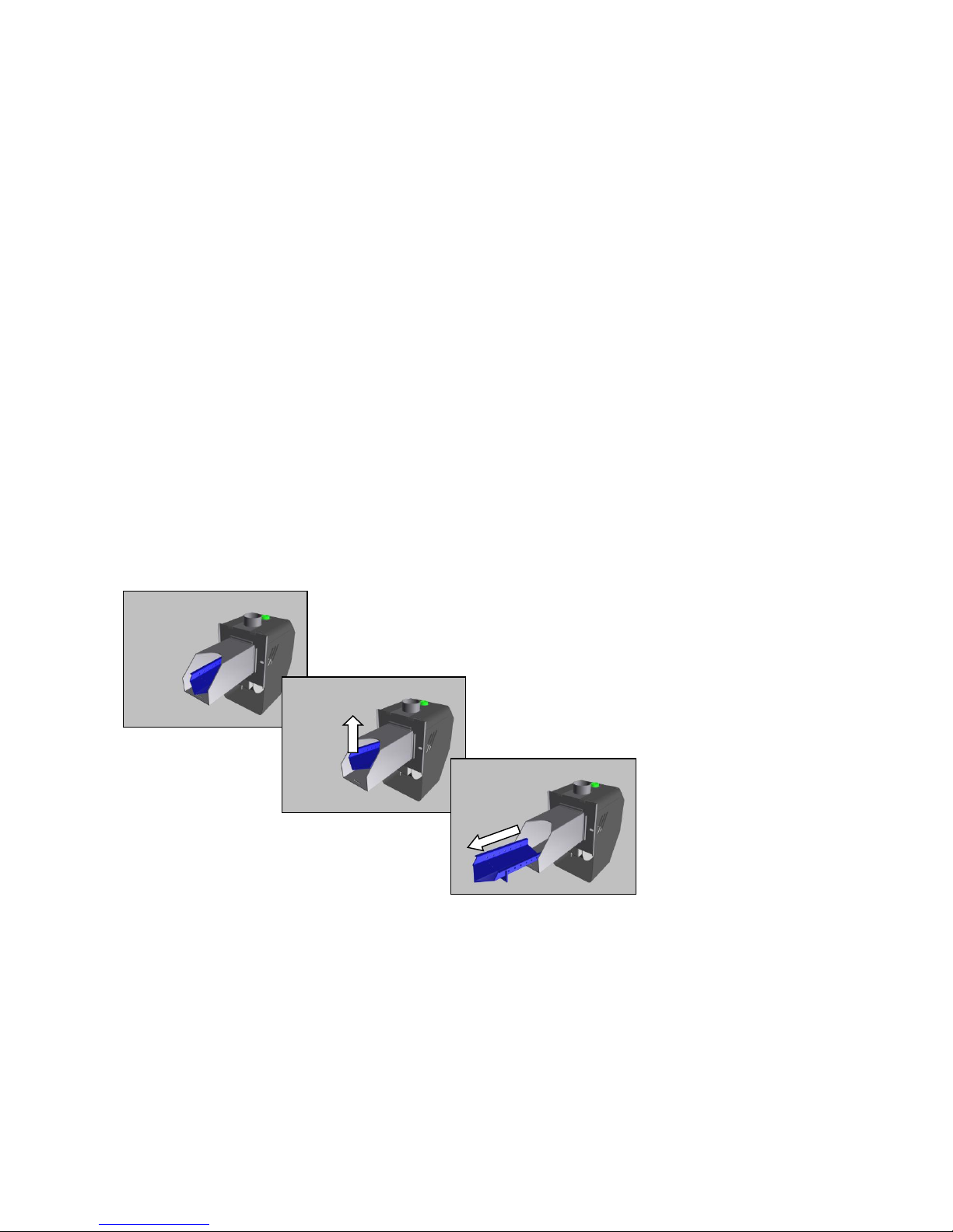
Cleaning the burner cartridge and inside the burner head is usually sufficient. This is done by lifting out the
burner cartridge and removing ash from this and from the burner housing (See the illustrations below).
It is also important to keep the light sensor clean.
Stop the burner and lift off the outside shield of the burner. Remove the light sensor; if any dust etc.,
remove it; clean the light sensor.
Check the function: Enter ”User’s Menu”, select ”Light sensor” and the point ”Current light strength”.
Cover the light sensor and read the value from the display; the read value should be between 5 to 8 points
under the value in the menu point ”minimum light strength” – adjust if necessary.
Check also the light value at full daylight of the sensor (daily light or lamp); should be over 200.
Page 27

27
6. Errors
Alerts for stoppages resulting from faulty equipment or ignition/operating errors caused by lack of fuel are
shown on the display in the direct text. At the same time errors in other parts of the burner equipment are
shown on the display.
The screen may appear as follows:
Critical alarms are cleared by pressing STOP once the cause of the alarm
has been eliminated. The display then returns to its normal status.
6.1 Alerts
It is recommended to use the test functions in the ”Service menu” in connection with the fault finding.
Alerts directly on main display:
Alert
Error causes
Rectification
ERROR in hot water tank
Extra sensor is defective (extra
sensor selected for hot water)
Check the connections to the terminal in the junction box; measure the
resistance via the sensor (should be
around 108 Ohm at 20 °C); if the
sensor is defective the burner will
continue until the set point is
reached (hot water function) or until
the boiler max. temperature is
reached (storage tank function);
perhaps change over to a kind of
operation without use of extra
sensor until a new sensor can be
installed.
Connection to extra sensor is cut off
(extra sensor selected for hot water)
ERROR in storage tank
Extra sensor is defective extra
sensor selected for storage tank)
Connection to extra sensor is cut off
(extra sensor function chosen to
storage tank)
Burner overheated (when the
burner is shut down there will be
an alert in the alert window)
The burner surface has become too
hot – bi-metal sensor is released.
The boiler needs to be cleaned – the
resistance through the boiler is too
big; negative draught in the chimney:
test by opening the chimney
cleanout door.
Bi-metal sensor is defective
The burner can be brought into
temporary operation by short
circuiting the terminals; the burner
must not operate without
supervision without operating bimetal sensor; to be replaced asap.
Connection to bi-metal sensor is cut
off.
Check the connections at the
terminals on the burner printed
circuit
Page 28

28
Alerts in alert window:
Alert
Error causes
Rectification
Auger circuit
The main plug on the burner is not correctly placed.
The plug is tight to place – press it to fit.
Condensator to the auger motor is either defective or
there is a loose connection.
If the condensator is defective operation can
only be established with a new condensator;
check the connections (terminals).
Loose connection: Cables from motor to print on
burner
Check all connections (terminals)
No fuel
The plug on the feeder motor is not correctly placed.
Remove the plug and check the plug in the
motor cabinet; try to place the plug again;
use the test function for outputs in ”Service
Menu” in order to test the function of the
motor: measure whether there is voltage in
the terminals.
There is a loose connection in the plug to the feeder
motor.
Check the plug; it might be necessary to
disassemble it in order to check the
connections in the screw terminals; test the
motor with the test function.
There is a loose connection in the plug on the feeder
motor.
See above.
The feeder auger is stuck
Test the function of the motor with the
output test in ”Service Menu”; if the motor
cannot rotate the feeder auger it might be
necessary to dismount the motor and test
without the load from the auger; firstly
check whether there is any voltage.
The feeder auger is full of sawdust
Test the quantity of fuel that the feeder
auger can give – see 4.2
The light sensor is defective
Remove the light sensor; go into the menu
”Light sensor” in ”User’s menu”; select
”Current light strength”; at daylight the light
sensor must show a value > 200
The light sensor is dirty
Remove the light sensor and check its
surface; clean the sensor and test its light
strength with the help from the menu
“Current light strength” in “Light sensor” in
“User’s menu”
The light sensor connection is loose
Check the light sensor’s connection in the
terminal on the print in the burner.
Burner overheated
The burner surface is too hot – the bi-metal sensor is
released
The boiler needs to be cleaned – the
resistance through the boiler is too big;
negative draught in the chimney: try to let
the chimney cleanout door be open.
Bi-metal sensor is defective
The burner can be brought into temporarily
operation by short circuiting the terminals;
the burner must not operate without
supervision without operating bi-metal
sensor; to be replaced asap.
Connection to bi-metal sensor is cut off
Check the connections at the terminals on
the burner print.
Boiler sensor
If the extra sensor is not used or if could be
left out, then exchange the 2 sensors.
Connection to boiler sensor is cut off
Check the connections to the terminal in the
junction box; measure the resistance via the
sensor. It should be around 108 Ohm at 20
°C.
Page 29

29
6.2 Failing to ignite
If the burner fails to ignite, this can have multiple causes.
Here are some of the most common combined with their symptoms:
After a failed ignition there is no or nearly no fuel in the burner:
o The plug to the feeder motor is loose:
The plug is not properly placed
The side of the plug mounted in the motor shield has been pressed into the
shield – sufficient contact cannot be achieved
Under cleaning or the like, the plug has been partly torn out of its seat
Go into the ”Service Menu” (press more than 3 seconds on the menu button);
chose the subject “Test of output” and try to start the feeder auger
Whilst the feeder auger operates try moving the feeder auger plug
After a failed ignition there is enough fuel in the burner:
o The ignition element is defective.
Test: Go into the ”Service Menu” (press more than 3 seconds on the menu button)
Chose the subject ”Test of output”
Chose ”Ignition”
You can manually inspect if the ignition element gets warm or not – take
care of your hands – do not touch the metal parts directly around the
ignition element.
o The fan speed is too high during the ignition:
Test: Go into the ”Service Menu” (press shortly on the menu button)
Chose ”Ignition” and hereafter ”Fan level”
The value shall be within 2 – 4%:
approximately 30 % (13 – 17 %) for burners with blank fan
approximately 3 % (2 – 4 %) for burners with black fan with the spark plug
located in a short pipe; approximately 15% with the spark plug located in a
long pipe
o The light sensor is defective.
o The light sensor is dirty.
Take out the sensor and check whether it is dirty – either sooty or covered by wood
dusts.
Go into ”User’s Menu”, chose ”Light sensor”, chose ”Current light strength”; when
the sensor is held in daylight or artificial lighting the value must be > 200.
o Cinders or ”hard” ashes are in the back of the burner and cover the air holes from the
ignition element
Remove ashes and cinders from the burners; be aware that no fuel is pushed into
the air holes in front of the ignition element;
Page 30

30
After a failed ignition too much fuel has built up in the burner – perhaps the complete boiler is
full
o The light sensor gets false light:
The jacket has been removed from the burner
The light sensor is not correctly placed
o The minimum light level is too close to the light level at no fire:
Test: Go into ”User’s Menu” (press shortly the menu button)
Select ”Light sensor”
Compare the actual light level with adjusted minimum level
If these are too close (distance < 5) – adjust the minimum light to make the
difference in the span 5 – 8
o The hysteresis of the light sensor is too low
Test: Go into ”Service Menu”
Select ”Light sensor” and sub-menu ”Hysteresis”
The value shall be at least 15; raise it to level 5
If this does not help - that is after a maximum adjustment of 10 – 15 – the
failure is not here; do not adjust any higher as this can shorten the lifetime
of the ignition element.
The ignition time (time between minimum light strength until ignition is off) can be extended: Go into
”Service Menu”, select ”Light sensor” and raise the hysteresis (default 15 => if minimum light strength e.g.
is 90, then the ignition stops when the light strength is 105); this can be used if the fuel is difficult to ignite
than normally (hard pellets).
Page 31
31
7. Product data
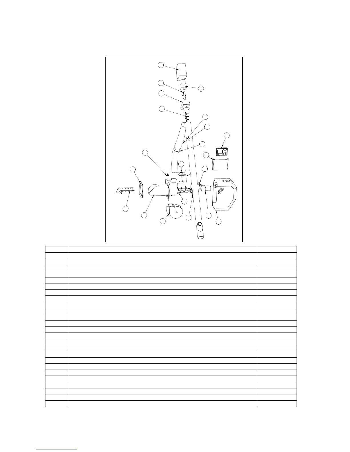
7.1 Spare parts Scandpell
Item
Description
Part no.
1
Burner housing
016024
2
Burner cartridge
016002
3
Fan (black model)
016003
5
Fan (blank model)
016030
4
Back plate for burner
016004
5
Ignition element
016005
6
Electrical connection plate
016006
7
Fibre gasket
016007
8
Burner auger motor
016008
9
Burner auger
016009
10
Flame sensor
016010
11
Feeder motor
016017
12
Feeder auger
016016
13
Auger pipe
016015
14
Feeder motor cover
016021
15
Anchor
016019
16
Anchor plate
016018
17
Burner cabinet
016011
18
Control unit
016040
19
Downpipe, metal
016013
20
Flexible downpipe
016012
21
Bi-metal sensor
016022
22
Control box
016025
-
Boiler temperature sensor
016026
-
Extra temperature sensor (5 meter)
016027
4
3
2
5
6
7
8
9
11
12
13
10
016000
14
15
16
19
20
21
17
Pos Vare nr. Tekst
1 016024 Brænderhoved
2 016002 Brænderzone
3 016003 Ventilator
4 016004 Bagplade for brænder
5 016005 Tændelement
6 016006 Elforbindelse
7 016007 Fiberpakning
8 016008 Sneglemotor brænder
9 016009 Snegl brænder
10 016010 Flammesensor
11 016017 Sneglemotor
12 016016 Snegl
13 016015 Snegle rør
14 016021 Kappe for snegl
15 016019 Aksel for snegl
16 016018 Holder for snegl
17 016011 Kappe for brænder
18 016014 Styring
19 016013 Rør for brænder
20 016012 Flexrørfor brænder
21 016022 Bimetalsensor
22 016025 Styringsboks
1
18
22
Page 32

32
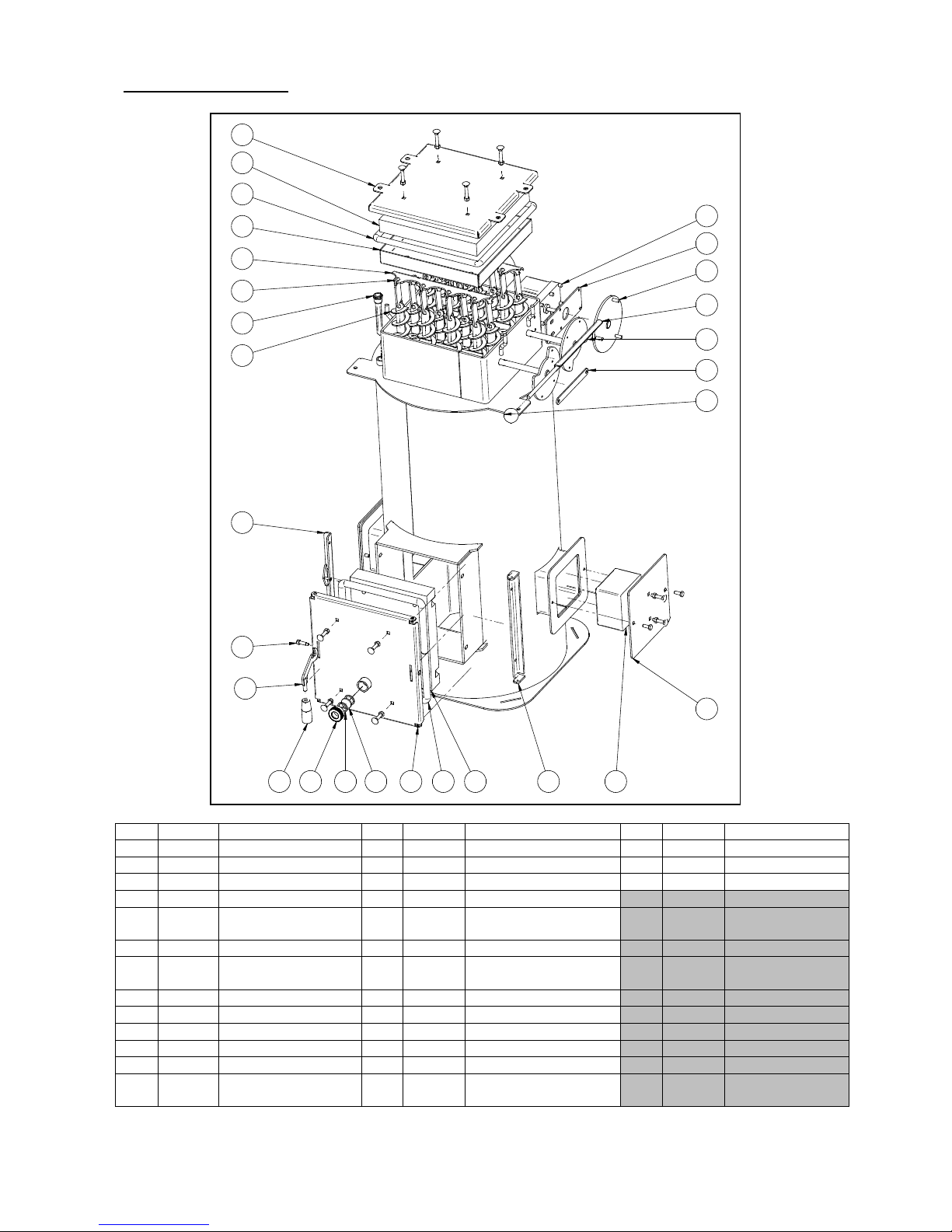
7.2 TPK Spare parts
Section 1 – cabinet:
Item
Part no.
Description
Item
Part no.
Description
1
015913
Base plate
7
015935
Adjustable plate
2
015915
Side panel
8
015934
Supports
3
015916
Back panel
9
015947
Internal control unit holder
4
015917
Front panel
10
015985
Blank panel
5
015918
Top
11
015948
Cover plate at fitting
6
015919
Cover
12
090004
Overheat thermostat
GODKENDT
INIT
BV
DATO
15-12-09
VARE BETEGNELSE
VG
VARE NR.
ENHED
VÆGT:
Reservedele TPK
015991
F1
1 2
3
4
5
6
8
7
9
11
10
12
Pos Vare Nr Vare betegnelse Enhed Antal
1 015913 Bundplade for Pellekedel Stk 1
2 015915 Sideplade for Pellets Stk 2
3 015916 Bagplade for Pellets Stk 1
4 015917 Forplade for Pellets Stk 1
5 015918 Låg for Pellets Stk 1
6 015919 Dækplade for røgkasse Stk 1
7 015935 Stilplade for stander Stk 2
8 015934 Stander for kappe Stk 2
9 015947 Holder intern styring TPK Stk 1
10 015985 Blindplade for styringshul Stk 1
11 015948 Dækplade ved beslag Stk 1
12 090004 Overkogs termostat 100°C Stk 1
Page 33
33
Section 2 – accessories
Item
Part no.
Description
Item
Part no.
Description
Item
Part no.
Description
1
015440
Ash door
14
015931
Plate - man. cleaning
27
015921
Cover
2
010084
Ash door hinge
15
015131
Hinge – man. cleaning
28
506012
Insul.stone – cover
3
050014
Centre bolt
16
015932
Turbulator
-
020493
Bushing *)
4
010085
Stone – ash door
17
015937
Panel – cleaning hatch
5
013240
Glass cord – ash door
18
015939
Insul. panel – cleaning
hatch
6
010081
Catch
19
015943
Insul. – cleaning hatch
7
011270
Gasket Ø30
20
015944
Glass cord – cleaning
hatch
8
013139
Inspection window
21
015940
Handle – man. cleaning
9
013367
1” surround
22
015941
Disc for cleaning motor*)
10
013155
Fastener
23
015942
Axel – cleaning motor
11
015924
Connecting rod
24
013055
Spherical handle
12
020003
Gear motor *)
25
013103
Cylindrical handle
13
015930
Attachment for gear
motor*)
26
012210
Sensor pocket
*) extra equipment
GODKENDT
INIT
BV
DATO
15-12-09
VARE BETEGNELSE
VG
VARE NR.
REV
AC
Reservedele TPK
015991
F1
7
26
1
10
6
3
2
24
425 8 59
15
27
11
13
14
16
17
18
21
22
23
19
20
12
28
Pos Vare Nr Vare betegnelse Enhed Antal
1 013001 Askelåge kpl SP Stk 1
2 013011 Hængsel for låge Stk 1
3 013007 Pasbolt Ø6xØ8x20 Stk 1
4 013090 Sten for askelåge Stk 1
5 013240 Glassnor for askedøre SP Stk 1
6 013006 Lukkekrog kpl. SP Stk 1
7 011270 pakning fiber Ø30Xø23x2 Stk 2
8 013139 Skue glas Ø30X3,3mm Stk 1
9 013367 1" omløber til skueglas Stk 1
10 013002 Lukkebeslag for låge Stk 1
11 015924 Forbindel se stang aotu rens Stk 1
12 020003 Gear motor 4,6 rpm Stk 1
13 015930 Beslag for rensemotor Stk 1
14 015931 Plade for manuel rens Stk 2
15 015131 hængsel for manuel rens Stk 1
16 015932 Turbulator Stk 1
17 015937 Plade for ren sedæksel Stk 1
18 015939 Isoleringsplade for rensedæk. Stk 1
19 015943 Isolering for rensedæksel Stk 1
20 015944 Glassnor Ø16 L= 1300 Stk 1
21 015940 Håntag for manuelrens Stk 1
22 015941 Rondel for rensemotor svejst Stk 1
23 015942 Aksel svejst for rensesystem Stk 2
24 013055 Kugle håntag Stk 1
25 013103 Håntag for låge Stk 1
26 012210 Dykrør Ø14,7x126x1/2" 3xØ6 Stk 1
27 015921 Dækplade for brændehul Stk 1
28 506012 Isoleringssten for blinddæksel Stk 1
29* 011314 Bræddebolt M8x40 Stk 2
Page 34
34
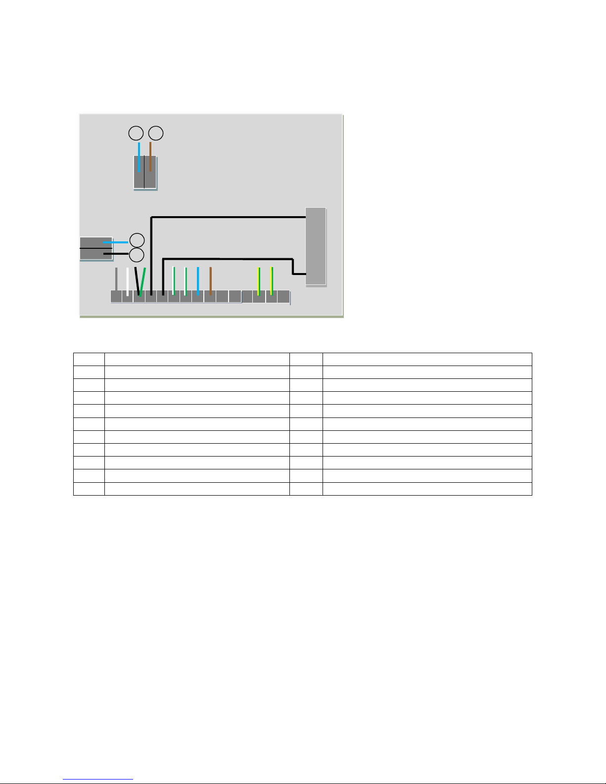
7.3 Electrical connection
7.3.1 Scandpell
7.3.1.1 Connections in the burner
Item
Description
Item
Description
1
Burner auger motor
11 - 2
Burner auger motor
12 - 3
Burner auger motor
13
Fan (earth)
4
Condenser
14
Earth for burner housing
5
Condenser
15 - 6
Ignition element
16
Light sensor
7
Ignition element
17
Light sensor
8
Fan (N)
18
Bi metal sensor (overheating sensor)
9
Fan (PH)
19
Bi metal sensor (overheating sensor)
10 -
7.3.1.2 Connection between the grey control box and the black operating panel.
The connection between the grey part of the control unit (mounted inside the cabinet) and the black
operating panel consists of a 4-conductor cable between the terminal blocks identified as terminals A-B. A
is connected to A, B to B etc.
1 2 3 4 5 6 7 8 9 10 11 12 13 14 15
16
17
18
19
Page 35
35
7.3.1.3 Connections inside the control unit
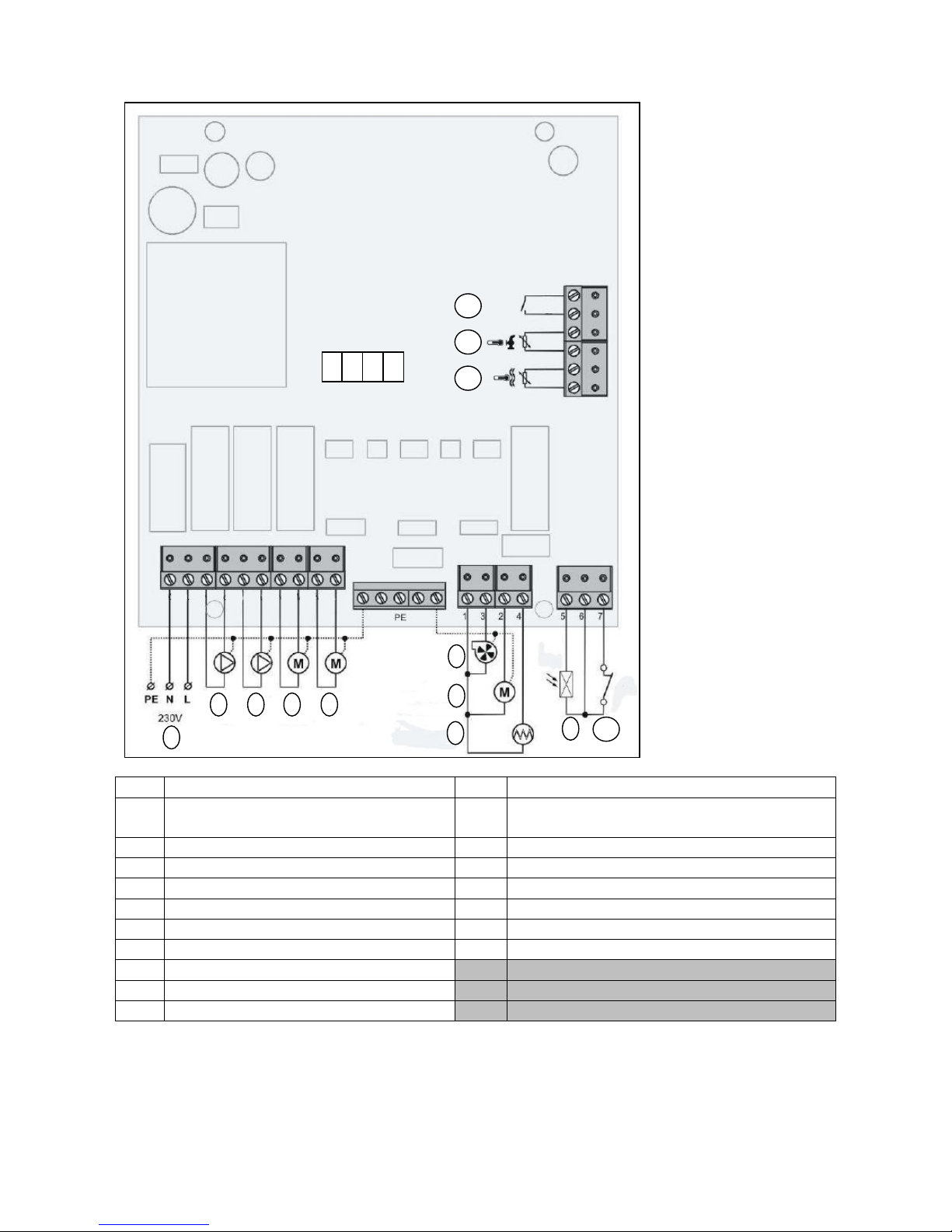
Item
Description
Item
Description
1
Mains connection (1x230 VAC, with a fuse
rated at max. 13 A)
11
External start/stop input
2
Boiler pump or circuit pump
12
Hot water sensor / storage tank sensor *)
3
Hot water pump
13
Boiler sensor
4
Cleaning motor (not fitted as standard)
A
Frame
5
Feeder motor
B
Data
6
Fan C 12 V
7
Stoker motor
D
Data 2
8
Heating element ignition)
9
Light sensor
10
Overheating fuse (sensor in the burner)
*) the temperature sensor is either used as hot water sensor or storage tank sensor.
1 2 3 4 5 6 7 8 9
111
1
N L N L N L N L
N L L L L N L
A B C D
Page 36

36
7.4 Operating safety Scandpell
7.4.1 Anti-burn-back protection:
The safety system has 3 levels against burn-back:
1. Continuously operating stoker auger (auger inside the burner itself)
2. A safety thermostat fitted on the burner head (monitors the temperature in the burner’s
prechamber)
3. A downpipe between the feeder auger and the pre-chamber (must be at least 500 mm)
7.4.2 Protection against loss of combustion air
If the fan does not operate during combustion, the feeder auger stops and an alarm is given on the display.
The burner will then have to be re-started.
7.4.3 Protection against the boiler overheating
When delivered with a Scandpell unit, the TPK is equipped with an overheat thermostat that is connected
on delivery to the power supply.
7.3.4 Function check of the safety system
NB: Any work involving high-voltage electrical connections should only be carried out by a
qualified installer
Testing fan function:
With the burner working, undo the wire in terminal 9 (phase supply to the fan) on the connection circuit
board in the burner.
The feeder must stop running during this.
Testing flame sensor monitoring
Test either during starting-up or during normal operation.
Remove the light sensor and cover it up so that it is in darkness.
If the burner starts up, the control unit must go into alarm mode after 3 ignition attempts.
If the light sensor is covered during normal operation, the control unit must attempt re-ignition. After 3
attempts, it must go into alarm mode.
Page 37
37
7.5 Dimensions, weight and output
7.5.1 Scandpell
Output
kW
6.5 – 24
Efficiency (together with TPK)
%
90 – 91
Weight
kg
16
Feeder auger length
m
1,6
Pellet size
mm
6 – 8
Mains supply
VAC
1 x 230
Min. combustion chamber depth
mm
450
Minimum chimney draw
mbar
0,1
Flue gas mass flow
Nominal output
kg/h
47,1
Minimum output
kg/h
19,8
Flue gas temperature
(at 20 °C room temp.)
Nominal output
°C
135
Minimum output
°C
80
Electrical supply
Voltage
VAC
230
Frequency
Hz
50
Required output (max at ignition)
W
300
Required output (operation)
W
80
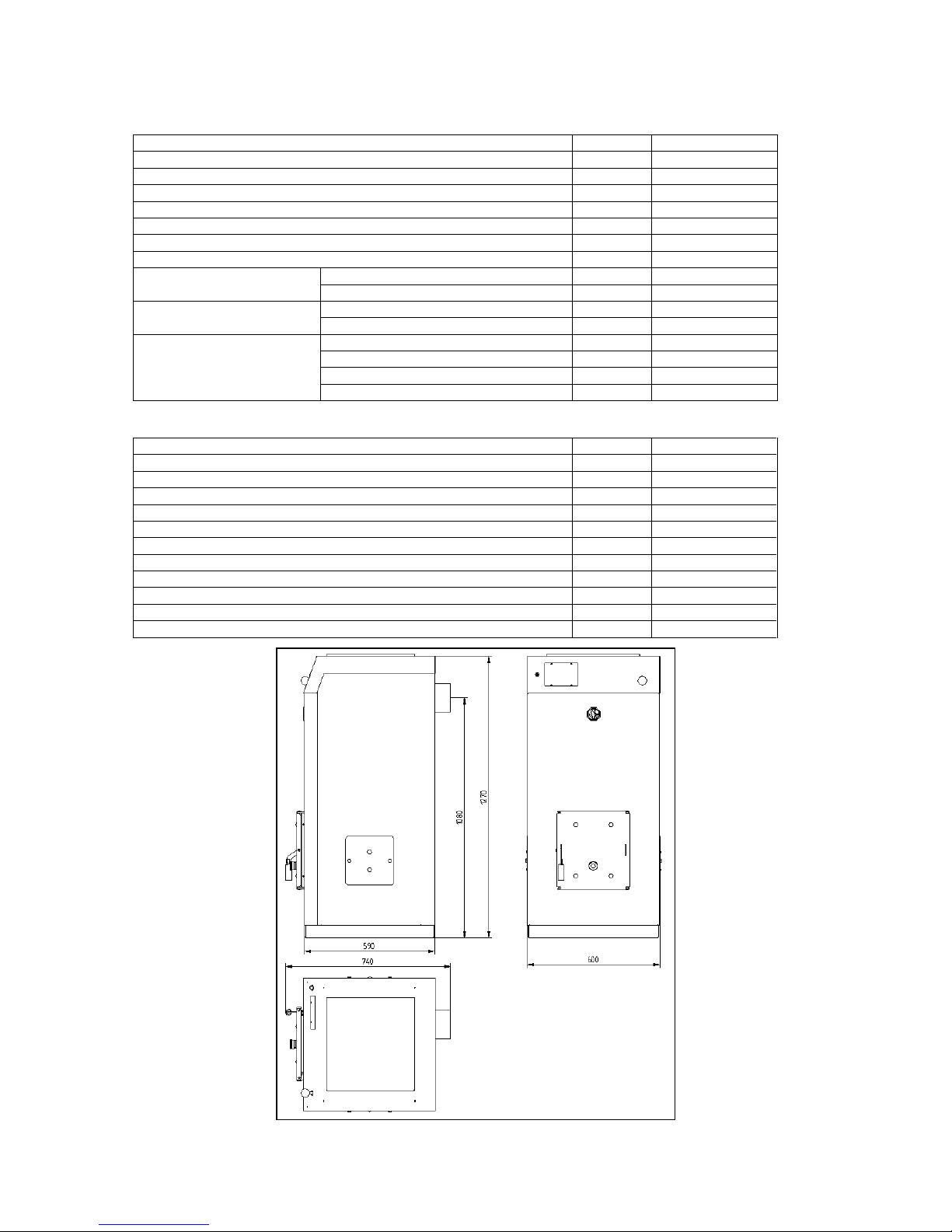
7.5.2 TPK
Output
kW
6.5 – 24
Efficiency (together with Scandpell)
%
90 – 91
Weight
kg
230
Combustion chamber depth
mm
520
Height incl. cabinet
mm
1270
Width (flange to flange)
mm
600
Depth (total)
mm
745
Depth (base plate)
mm
590
Height to flue gas connector (centre)
mm
1080
Flue gas connector diameter
mm
Ø129
Water content
Litres
75
Water side resistance (at 1,9 m2/h and T = 10)
mbar
8
Page 38

38
8. EEC declaration of conformity
Page 39
39
9. Test certificate
Page 40

40
Rev. 11/100913
 Loading...