

HST HD102B Installation And Maintenance Instructions Manual
INSTALLATION AND MAINTENANCE INSTRUCTIONS
HD102B
Conventional Heat Detector
Before Installing
NOTICE: This manual should be left with the owner/user of this equipment.
IMPORTANT: This detector used with the HD10X base must be tested and maintained regularly following NFPA 72
requirements. The detector should be cleaned at least once a year.
General Description
This detector can be used in all areas where heat detector is required. It is suited for fires ranging from heat to flaming fires.
This detector is designed to provide open area protection and to be used with most conventional fire alarm control panel.
Two LEDs on each detector provide local 360° visible for indication of status. In the normal condition the LEDs flash red
every 5 seconds. When the detector senses heat goes into pre-alarm sensitivity the LEDs will flash red every 1 second. When
the detector senses heat and goes into alarm the LEDs will latch on red.
The alarm can be reset only by a momentary power interruption.
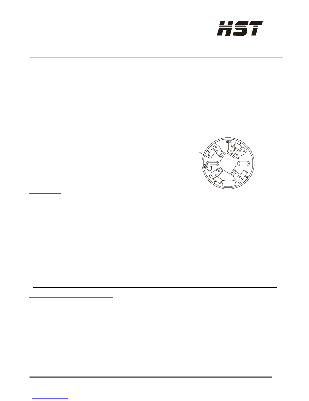
Base Terminals
No. Function
1 Remote Indicator (-)
2 Power (-), In
3 Power (-), Out
4 Power (+), Remote Indicator (+)
Specifications
Operating Voltage Range: 16 to 28VDC Volts Non-polarized
Standby Current: 40µA @ 28 VDC(Maximum)
Alarm Current (LED on: ) 30mA @ 28 VDC(Maximum)
Temperature Class: A2R
Operating Temperature Range: 14°F to 122°F (-10°C to50°C)
Operating Humidity Range: 10% to 93% Relative Humidity, Non-condensing
Height: 2.2˝ (55 mm) installed in Base
Diameter: 4.0˝ (103 mm)
Weight: 5.5 oz. (155 g)
Color & Material White/ ABS
Bases HD10X
Compatible control panels Conventional fire alarm control panel
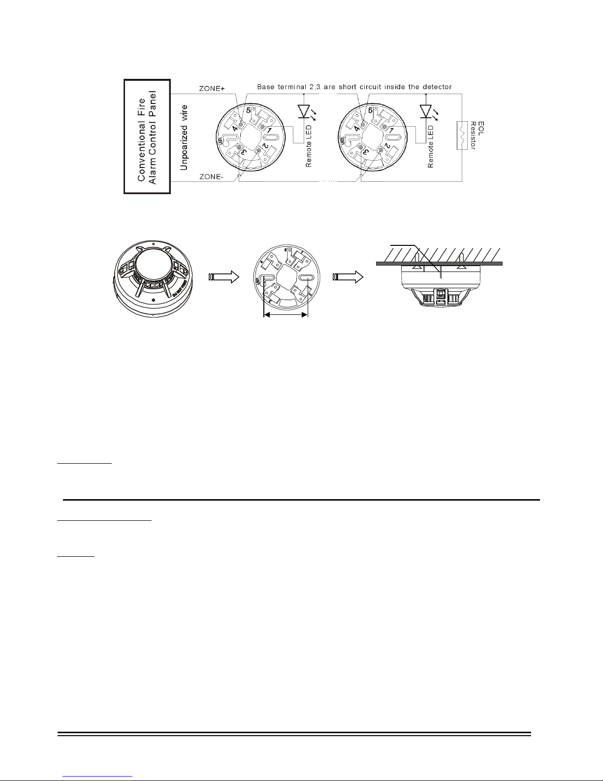
Installation Guidelines (See Figure 2)
All wiring must be installed in compliance with the local codes having jurisdiction. Proper wire gauges should be used. The
conductors used to connect heat detectors to control panels and accessory devices should be color-coded to reduce the
likelihood of wiring errors. Improper connections can prevent a system from responding properly in the event of a fire.
For signal wiring (the wiring between interconnected detectors), it is recommended that the wire be no smaller than 1.0
square mm. Wire sizes up to 2.5 square mm may be used with the base. For best system performance. The Power (+) and
Power(-) wires should be twisted pair and installed in separate grounded conduit to protect the loop from extraneous
electrical interference.
Heat detector and fire alarm system control panels have specifications for allowable loop resistance. Consult the control
panel manufacturer’s for the total loop resistance allowed for the particular model control panel being used before are made
by simply stripping about 3/8 inches (9.5 mm) insulation from the end of the wire. Sliding the bare end of the wire under the
HLogic Security Technology Co., Ltd www. hstfire .com Document Ref: M2115-04 Issue: 5.3 07/2015
Base Terminal
Figure 1. Terminal layout of HD10X base
©
clamping plate.
The wiring of the detector base should be checked before the detector heads are installed in them. The wiring should be
checked for continuity ,polarity in the base, and dielectric tests.
Note: During the installation, Make the rib of the detector align with the rib on the base until it drops into place.(see figure 3)
Note: Dust covers are an effective way to limit the entry of dust into smoke detector sensing chambers. However, they may
not completely prevent airborne dust particles from entering the detector. Therefore, We recommends the removal of
detectors before beginning construction or other dust producing activity.
Be sure to remove the dust covers from any sensors that were left in place during construction as part of returning the system
to service.
Remote LED
The remote indicator is connected between terminals 1 and 4 as showing Figure 2. The remote indicator must be current
limited to 20mA @24V. Maximum. Not limiting current could result in damage to the detector or cause a no alarm condition.
Tamper-Resistance
The detector include a tamper-resistant capability that prevents their removal from the bracket without the use of a tool.
Testing
Before testing, notify the proper authorities that the system is undergoing maintenance, and will temporarily be out of
service. Disable the system to prevent unwanted alarms.
All sensors must be tested after installation and periodically thereafter. Testing methods must satisfy the Authority Having
Jurisdiction (AHJ). Sensors offer maximum performance when tested and maintained in compliance with NFPA 72.
The sensor can be tested in the following ways:
Direct Heat Method (Hair dryer of 1000 – 1500 watts)
1. From the side of the detector, direct the heat toward the sensor. Hold the heat source about 6 inches (15cm)
away to prevent damage to the cover during testing.
2. The LEDs on the detector should light when the temperature at the detector reaches the alarm set point. If the LEDs fail to
light, check the power to the detector and the wiring in the detector base.
3. Reset the detector at the system control panel.
HLogic Security Technology Co., Ltd www. hstfire .com Document Ref: M2115-04 Issue: 5.3 07/2015
Figure 2. Typical wiring diagram
60mm
Figure 3. Install the detector
Rib
Detector Base Installed
 Loading...