

HSS Hire HW038 Operating & Safety Manual
MMA/TIG
AC/DC
Inverter
200 amp
A professional inverter welder with
HF & lift TIG ignition.
Operating & Safety Guide HW038
Set the AC / DC selector as required. Note that
when AC is selected the current wave balance can
be altered via the balance button.
Fit the regulator to an Argon gas cylinder then
connect the gas hose to the regulator and the gas
inlet at the rear of the unit.
STICK WELDING...
Clip the earth clamp to a patch of clean, bright
metal on the workpiece as close to the weld
as possible.
Holding the welding rod at an angle of 60-70
degrees to the surface, move it towards the work
until you strike an arc.
Keep the arc about 3mm long, work slowly along
the weld in a series of semicircular sweeps across
the line of the joint.
Chip off any slag build-up on the weld before
making a second pass along the joint.
Always begin by making a test weld and adjust the
settings as necessary.
TIG WELDING....
Turn on the Argon gas cylinder and adjust the
regulator until the TIG unit’s float gauge registers a
flow of 8-12 litres per minute when you push the
torch button.
Switch the welder ON and adjust the welding
current to the amperage required.
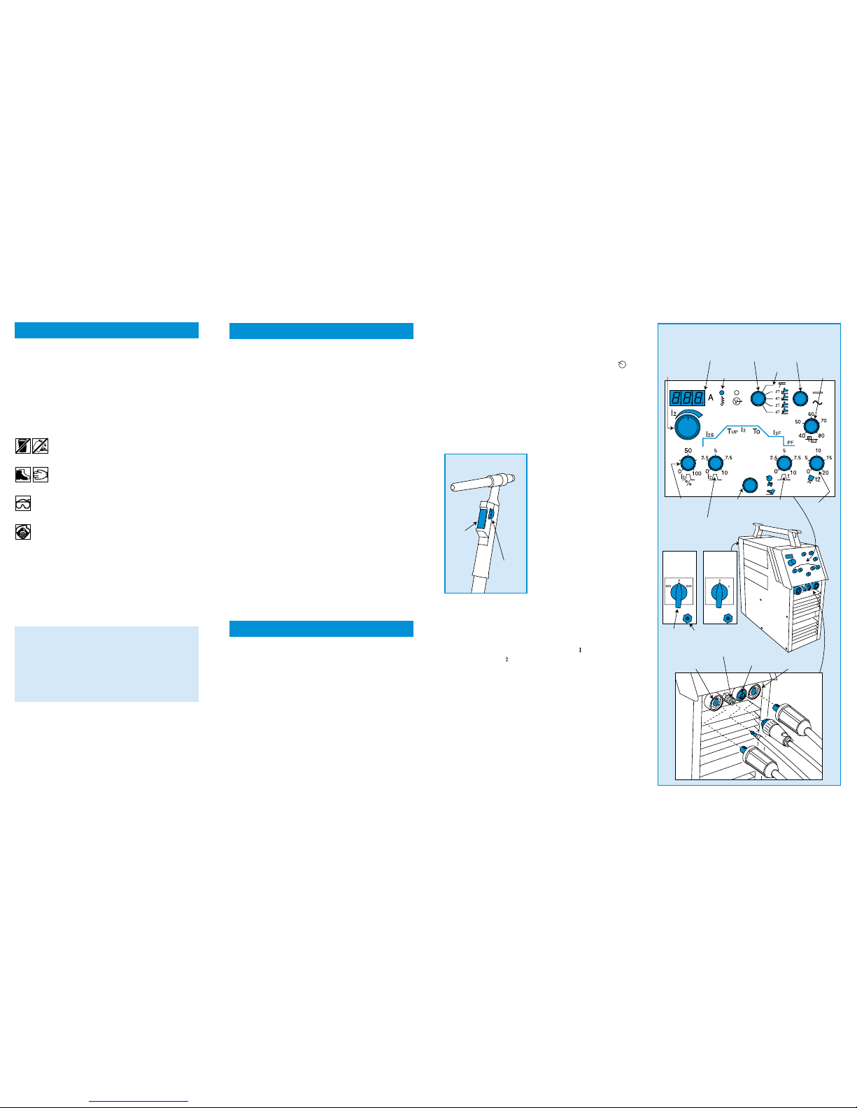
The torch has a dial fitted, which allows the
operator to adjust the amperage while welding. To
use this facility, turn the current control mode selector to
the symbol. The adjuster dial will only decrease the
amperage from the current displayed on the LED, it
cannot increase it.
If the HF setting has been selected, hold the
welding torch at an angle of 60-70 degrees to the
workpiece and about 3mm from the surface, then
press the torch control button to strike an arc.
If the Lift TIG setting has been selected hold the
welding torch with the electrode in contact with
the workpiece press the torch control button and
raise the electrode clear of the surface to strike
the arc.
As soon as a pool of molten metal forms, simply
move the torch slowly along the joint, keeping it at
a constant angle and distance from the surface.
If necessary feed a length of filler rod into the weld
pool’s leading edge as you go.
BASIC TECHNIQUES
Never push the equipment beyond its design
limits. If it will not do what you want with reasonable
ease and speed, assume you have the wrong tool for the
job. Contact your local HSS Hire Shop for advice.
The welders electronic system is protected
against damage from overheating. If overheating
occurs, the system will shut down the welding
process until it has cooled. This is indicated by the
amber temperature lamp.
Keep the equipment clean. You will find this less of a
chore if you clean up regularly rather than wait until the
end of the hire period.
When not in use, store the equipment somewhere
clean, dry and safe from thieves.
If TIG welding, replace the gas cylinder as soon as
it runs out. Simply turn OFF and unscrew the regulator
then remove the old cylinder and fit a new one.
Turn off the gas cylinder if leaving the unit
unattended to reduce gas loss through leakage.
IF TIG WELDING…
Turned OFF the Argon gas supply at the cylinder,
switch OFF the welder then disconnect the gas
cylinder.
WHATEVER YOU ARE USING…
Leave everything to cool off before removing the
earth-clamp from the work and disconnecting all
of the unit’s welding leads.
Finally, neatly coil all leads and hoses, ready for
return to your local HSS Hire Shop.
FINISHING OFF
EQUIPMENT CARE
Code 55332/55334
©HSS Hire Service Group Plc 2000 No. HW038/01
Group Office: 25 Willow Lane, Mitcham, Surrey CR4 4TS
Web Site: http://www.hireweld.com
Contact your local
0845 728 2828
…any comments?
If you have any suggestions to enable us to improve
the information within this guide please fax your
comments or write to the Product Manager at the
address below
Fax: 020 8687 5001
HW038/01
For advice on the safety and suitability of this equipment
contact your local HSS Hire Shop.
There is a serious risk of personal injury if you do
not follow all instructions laid down in this guide.
This equipment should be used by an able bodied,
competent adult who has read and understood these
instructions. Anyone with either a temporary or permanent
disability should seek expert advice before using it.
Keep children, animals and bystanders away from
the work area.
Never use this equipment if you are ill,
feeling tired, or under the influence of
alcohol or drugs.
Skin must be covered – protective
clothing, footwear and gauntlets must
be worn.
A head shield with a 10 EW shade MUST be
worn by anyone in the work area – goggles
are not suitable.
Fumes produced by the welding process, if
inhaled, can be harmful to health. A suitable
welding mask must be worn when using this
equipment. Respiratory protective equipment is available
for hire, contact your local HSS Hire Shop for details.
A fume extractor or smoke eliminator should be
used in the work area.
If the head shield or lens becomes damaged, return
it to your local HSS Hire Shop for exchange.
Never use welding equipment near any combustible
gases or materials.
Never use welding equipment near computers or
any sensitive electronic equipment.
Always transport, store and operate the machine in
an upright position.
Keep the power unit’s air vents clear of all
obstructions.
Always switch the equipment OFF before making
any adjustments to it. Never leave it switched ON
and unattended.
Let It Cool
Handle welding equipment and work with
care – it will be hot. Leave equipment to cool
before changing welding rods or moving
earth clamps.
GENERAL SAFETY
The HSS 200amp Inverter Welder is available in
two model types, a single voltage 240V PFC
(power fluctuation control) or a dual voltage
240V/415V standard model.
If using a 240V supply the unit can be connected
using a 32A (blue) 240V plug (not supplied) or be
wired direct to a 35A dedicated fuse on the
consumer unit.
If using a 415V 3-phase supply, connect the two
supply wires to two phases and connect the earth
wire to the earth connection.
Whichever you are using, all connections may only
be made or removed by a qualified electrician. Do
ensure the electrician sets the unit’s ON/OFF
switch to suit the supply voltage, failure to do so
could cause the unit to ‘burn out’.
If the equipment fails, or if its power supply cable
becomes damaged, return it. Never try to repair
it yourself.
Keep cables out of harm’s way, and clear of the
work area.
Extension leads should be fully unwound and
loosely coiled, away from the equipment. Never run
them through water, over sharp edges or where they
could trip someone.
Keep the equipment dry, using electrical
equipment in very damp or wet conditions can
be dangerous.
Ensure the welder and the power socket are switched
OFF before plugging into the power supply.
Ensure the workpiece is clean, dry and free from
rust, paint and grease. Aim to weld only bright,
bare metal.
Clamp workpieces securely in their final positions
to stop them moving during welding.
STICK WELDING, (MMA)…
For general purpose welding of mild steel/
fabrication, ideal where applications restrict the
use of gas (oxy-acetylene) systems.
Connect the welding torch and earth clamp to
the terminals on the front of the unit.
The electrode holder to the (+) positive, earth
clamp to the (–) negative.
Attach the earth clamp to the workpiece and fit an
appropriate welding rod to the electrode holder.
GETTING STARTED
ELECTRICAL SAFETY
Turn the function switch to the electrode holder
sign (top) and select the welding mode AC or DC
with the AC/DC switch. Now switch the welder ON
(there is an ON/OFF switch at the rear of the casing).
Turn the current control mode selector to the
then turn the welding current control knob
until the required welding amperage is displayed
on the LED. You are now r eady to stick/MMA weld.
TIG WELDING CONTROLS...
(Tungsten Inert Gas Shield) Used mainly in the
petrochemical industry for welding stainless steel,
aluminium and specialist pipelines.
Ensure the welder is switched OFF and isolated
from its power supply.
Connect the TIG torch and
earth clamp to the
terminals on the front of
the unit, this time with
the earth clamp to the (+)
positive. The TIG torch
has a seven-pin connector
and a gas supply hose,
which should both be
connected.
Set the function switch to
one of the four available
settings.
These settings effect the
way the torch reacts to
each press or release of
the button.
2T (two-touch) press to activate torch, release to
deactivate.
4T (four-touch) press for gas, release to weld, pr ess
again for slope down and release for post flow.
The symbols next to the torch represent the type
of welding current. Either Lift-TIG ( ) or HF-TIG,
high frequency ( ).
If Slope Up (the period of time taken for the current to
increase from establishment of an arc) is to be utilised
set the slope up dial to the required setting (graded
in seconds).
If Slope Down (the period of time taken for the current to
decrease from release of the torch button) is to be utilised
set the slope down dial to the required setting.
When slope is selected, turn the current
percentage dial to select a % of the welding
current, which the slope up will start from and
slope down will close to.
Set the post flow dial (the period of time, after the
welding current has stopped, that gas continues to flow)
as required.
Dual
Voltage
Model
240V
Model
Welding
Current
Control Knob
Current
LCD
Temperature
Lamp
Function
Switch
Stick
Weld
AC/DC
Switch
Balance
Button
Current
Percentage
Dial
Slope
Up
Current
Control
Mode
Selector
Slope
Down
Gas Post
Flow
Gas
Inlet
Gas
Connection
Tig Torch
Socket
+ Connection
– Connection
ON/OFF
Switch
Current
Adjuster
Dial
Torch
Control
Button
TIG Torch
MMA/TIG AC/DC Inverter
 Loading...