

Page 1
MANUAL
HK2 – HK4 25-08-2014
Page
1
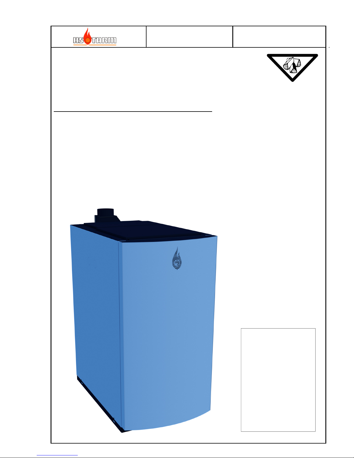
HK2, HK3, HK4 STD
(Bonus 30 MK2, Excellent 30, Boréale, Bonus 30, Solo Innova 30 MK2, Excellent 40,
Fjord 30, Solo Plus 30, Solo Innova 50 MK2, Excellent 50, Fjord 50 and Solo Plus 50)
Wood log central heating boilers
Chapter
User instructions and regular maintenance (1)
Extra and optional accessories available (2)
General conditions of sale and guarantee (3)
The product produced by HS
TARM A/S type:
HK2, HK3 and HK4
made according to:
• EMC Directive
(89/336/EEC incl.
modification 92/31/EEC
and 93/68/EEC)
• LV Directive 2006/95/EEC
• PE Directive 97/23/EEC
• Standard EN 303-5:2012
Efficiency class 5
Emissions class 5
Page 2

MANUAL
HK2 – HK4 25-08-2014
Page
2
TABLE OF CONTENTS
The content of this manual is susceptible to modification by the manufacturer without notice.
Content
1
USER INSTRUCTIONS AND MAINTENANCE .................................................................................................3
1.1 D
ESCRIPTION OF THE HEATING BOILER AND CONTROL PANEL
......................................................................................3
1.1.1 Use of the heating boiler with storage tank (See page 3): ......................................................................................5
1.2 R
ESPONSIBILITY, SECURITY AND DUTY OF USER
..........................................................................................................6
1.2.1 Responsibility .........................................................................................................................................................6
1.2.2 Rules of safety .........................................................................................................................................................6
1.2.3 Duties of user..........................................................................................................................................................6
1.2.4 Local installation requirements ..............................................................................................................................6
1.3 G
ENERAL INSTRUCTIONS OF USE
.................................................................................................................................7
1.3.1 The wood, solid fuel ................................................................................................................................................7
1.3.2 Before the first use: ................................................................................................................................................7
1.3.3 First and regular use ..............................................................................................................................................8
1.3.4 Primary and secondary air settings ........................................................................................................................9
1.3.5 Fine tuning of the secondary air.............................................................................................................................9
1.3.6 Minimum flue gas temperature setting, only for installer or advertised user. ........................................................9
1.3.7 Boiler temperature setting, only for installer or advertised user. ..........................................................................9
1.3.8 Safety thermostat (STB) – situated on front left of controller ............................................................................... 10
1.3.9 Ash door locking ................................................................................................................................................... 10
1.3.10 Fuse .................................................................................................................................................................. 11
1.3.11 Quick break down search (considering that the hydraulic attachment is correct)........................................... 11
1.3.12 Cleaning and regular maintenance .................................................................................................................. 12
1.3.13 Door silicone gaskets ....................................................................................................................................... 14
1.3.14 Wear and tear of the refractory material, hanging plates and seals ................................................................ 16
2
EXTRA AVAILABLE ACCESSORIES ............................................................................................................... 17
2.1 S
TORAGE TANKS
........................................................................................................................................................ 17
2.2 L
ONG SENSOR THERMOMETER
150MM ....................................................................................................................... 17
2.3 H
YDRAULIC RECYCLING KIT D
60°C ........................................................................................................................ 17
2.4 D
OMESTIC HOT WATER KIT
...................................................................................................................................... 18
2.5 D
RAUGHT REGULATOR
.............................................................................................................................................. 18
2.6 E
LECTRIC HEATER
..................................................................................................................................................... 18
3
INSTALLATION INSTRUCTIONS..................................................................................................................... 19
3.1 T
ECHNICAL DATA
...................................................................................................................................................... 19
3.2 C
HIMNEY AND FLUE GAS PIPES CHARACTERISTICS
.................................................................................................... 22
3.3 C
ONNECTING THE BOILER TO THE CHIMNEY
.............................................................................................................. 23
3.4 D
RAUGHT (LIFTING FORCE
) ....................................................................................................................................... 23
3.5 S
AFETY / EXPANSION
................................................................................................................................................. 24
3.6 A
DJUSTMENT OF TEMPERATURE SETTINGS, SENSOR LOCATION
................................................................................. 25
3.7 B
OILER CONNECTIONS / STORAGE TANKS
.................................................................................................................. 26
3.8 E
LECTRICAL CONNECTIONS
....................................................................................................................................... 27
3.9 C
ONTROLLER PARAMETERS
....................................................................................................................................... 28
3.10 A
LARM CODES
........................................................................................................................................................... 28
3.11 C
ONTROLLER INDICATIONS (FUNCTION MODE
) .......................................................................................................... 28
3.12 C
ONTROLLER FUNCTION EXPLANATION
..................................................................................................................... 29
3.13 M
AIN HYDRAULICS
.................................................................................................................................................... 31
3.13.1 Principle of the hydraulic recycling ................................................................................................................. 31
3.13.2 Installation diagram – simple system ............................................................................................................... 32
Page 3

MANUAL
HK2 – HK4 25-08-2014
Page
3
1 User instructions and maintenance
1.1 Description of the heating boiler and control panel
1) Control panel
2) Loading door
3) Primary air setting (intake)
4) Secondary air setting (intake)
5) Ash door
6) Visual flame control
7) Combustion tunnel
8) Secondary air combustion inlet
9) Primary air combustion inlet
10) Removable h
eat plates
11) Tubular heat exchanger
12) Flue gas box
13) Suction fan
14) Cleaning / soot hatch
15) Cooling coil
16) Flow
17) Return
18) Ignition door (only HK3 and HK4)
3
18
1
4
15
2
13
11
17
9
7
5
6
8
10
12
14
14
16
Page 4
MANUAL
HK2 – HK4 25-08-2014
Page
4
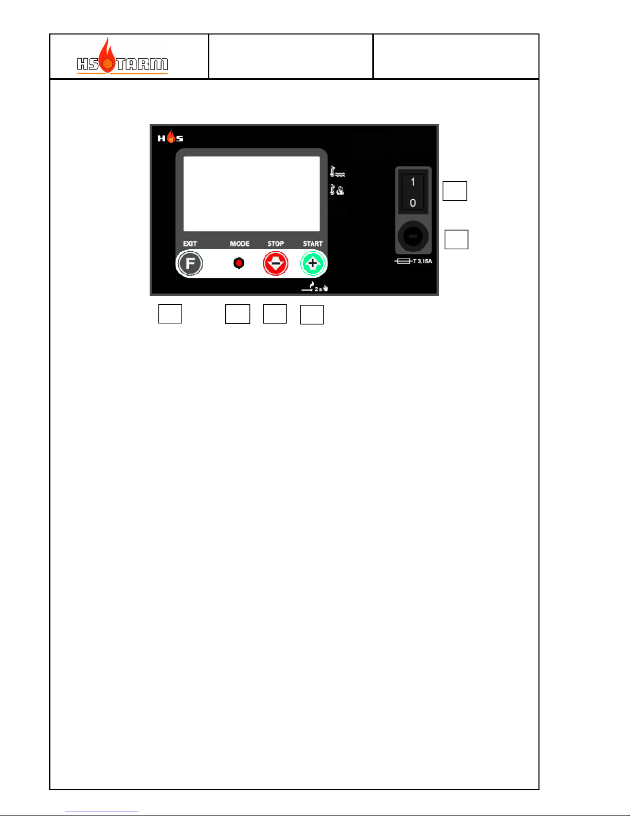
Control panel
(A) Function button; short press: shifts between boiler and flue gas temperature
indication; long press: access to parameters behind PIN code
(B) LED indicator
(C) STOP and minor setting button
(D) START and higher setting button
(E) Main fuse
(F) Mains ON/OFF
Detailed description of the boiler (see paragraph 1.1)
1. Control panel
2 Loading door These dimensions allow easy wood loading
3 Primary air setting Adjust the primary air necessary for the combustion.
4 Secondary air setting A
djust the secondary air necessary for the combustion
5 Ash door Behind this door, the combustion take place. This door is also
used to take away the ashes regularly.
6 Flame control sight glass This sight glass is used to set up the combustion.
7 Tunnel This is the heart of the combustion.
8 Secondary air exit The secondary air enters the combustion in the high
temperature zone
9 Primary air exit The primary air is diffused in through the wood logs
10 Removable heat plates They limit the shooting up of the boilers body and diffuse
the primary air
11 Tubular heat exchanger The tubular heat exchanger is used to recover the heat from
the flue gases. They are equipped with turbulators.
12 Flue gas box Collect the flue gas and ashes before evacuation.
13 Suction fan Brings the necessary air for the combustion.
14 Cleaning hatch The cleaning is regularly done by this hatch.
15 Cooling coil It serves to cool down the boiler in case of overheating.
16 Flow
17 Return
A
B
C
D
E
F
Page 5
MANUAL
HK2 – HK4 25-08-2014
Page
5
1.1.1 Use of the heating boiler with storage tank (See page 3):
The HK boilers are wood log boilers, for chopped wood having the same length as loading
chamber. The good performance links to the association of a minimum storage tank volume.
It is not a continuous fire like a stove. An essential characteristic of the boilers is the
presence of a suction fan situated in the flue gas exit on the back of the boilers.
The primary and secondary air leads to the combustion zone by ducts to obtain an ideal air
speed and mixture for ideal combustion.
The primary combustion air runs through the primary air valve (3) into the side of the lower
part of the loading chamber. The position of this valve adjusts the rate of air necessary to
generate the power.
The secondary air streams at high speed to the hot zone of the combustion by valve (4). It
enters through the ceramic slot (visible by the loading door) and diffuses through the
diffuser holes situated in the combustion air-mixing slot.
The combustion continues from the hot air-mixing slot into the combustion tunnel in which
the combustion finalizes at very high temperature (1000°C to 1200°C), thus minimizing
pollution and production of ash and optimizing the efficiency.
The best efficiency / combustion obtained by having a good control of the primary and
secondary air, according to characteristics of combustion (calorific power of the type of
wood, hygrometry and age). This implies that the fan works continuously when there is
wood in the boiler, and so that the boiler can permanently evacuate the energy produced by
the combustion. To obtain the correct way of working requires installing of a hydroaccumulation volume with the correct dimensions (energy storage / storage tank).
The role of energy storages is to ensure good working of the boiler even when the energy
demand is weak (mild days of winter, autumn, spring, summer). It is a matter of absorbing
the surplus of energy produced by the boiler. This stored energy will be returned to the
heating system and in the domestic hot water according to demand. Thus, when the storage
tank(s) are full of energy (75°C or 80°C at the lowest point) the boiler must be empty of
wood, must not be reloaded, and the suction fan will stop working . The boiler will be
reloaded with wood when the storage tank(s) will be emptied of their energy (30°C to 40°C
at the highest point according to the type of installation, without active take over; 60°C at
the highest point with an active take over) with only the necessary quantity of wood to
reheat the storage tank(s). It is possible to reload the boiler with wood before the storage
tank(s) become completely emptied of their energy (for example at night before going to
bed), but loading only the quantity of wood necessary to reheat the storage tank(s).
So it is necessary to always consult the different thermometers of the storage tank(s) to
know the quantity of wood that you can load. This system supplies the energy with optimum
efficiency and a normal function, which ensures autonomy.
Thus this system allows the boiler running in the best conditions and avoids the slowing
down phases (the boiler in high temperature, boiler still loaded, very weak energetic
demand, suction fan stops). The slowing down provokes a bad function, an abnormal soot
build and premature use of the boiler by a corrosion due to the acids in the woods which
have not been burnt. Therefore, it is vital never to reload the boiler when the storage
tank(s) are full of energy. It is necessary to let the fire shut down if the storage tanks
discharging are long (weak energetic demand). HK boilers are not continual fire boilers.
Page 6
MANUAL
HK2 – HK4 25-08-2014
Page
6
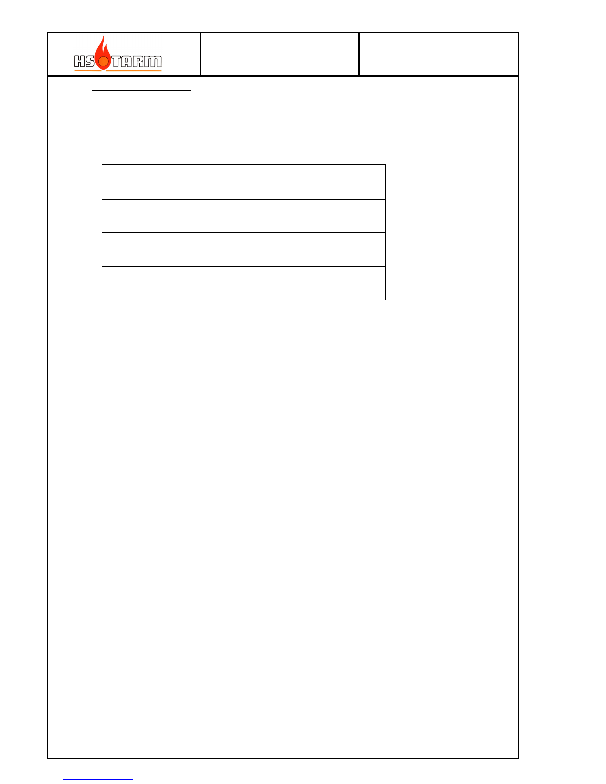
Guarantee and claims
If the boiler is not connected to a storage tank of at least the size as stipulated in the below
table, the guarantee accorded by the constructor is not valid.
The useful storage tank volume:
Volume in
liters
Obligatory minimum
working volume
Advised working
volume
HK2 1250 1500
HK3 1750 2000
HK4 2250 2500
1.2 Responsibility, security and duty of user
1.2.1 Responsibility
The user is responsible for the use of the boiler. The user shall at all times respect the
instructions given in this manual. Failing to follow the instructions will jeopardize the
function of the boiler, its efficiency, its life-duration, increase waste pollutants, and cancels
the guarantee on the product.
It is understood that the user shows a real willingness and capacity to the use a wood log
combustion boiler, and appreciate that a biomass heating system constitutes a workload and
the necessary obligations reduces the advantages offered by the ecologic combustible fuel.
1.2.2 Rules of safety
In the case of defects or poor functions, it is necessary to call your heat installer. A sufficient
air supply (ventilation) in the heating room is necessary, and it shall never be obstructed.
Never store dangerous or inflammable material in the heating room. Do not let children near
the boiler. Do not let unqualified people use the boiler.
1.2.3 Duties of user
The user must maintain very regularly the boiler, the installation, and to fulfill in particular:
- General rules of safety
- The respect of these directions
- The respect of instructions relating to the accessories
- The current regulations. An annual maintenance by a qualified
professional is advisable.
1.2.4 Local installation requirements
Be aware of local building regulations, which can call for special initiatives for the installation
of this boiler and its accessories.
Page 7
MANUAL
HK2 – HK4 25-08-2014
Page
7
1.3 General instructions of use
1.3.1 The wood, solid fuel
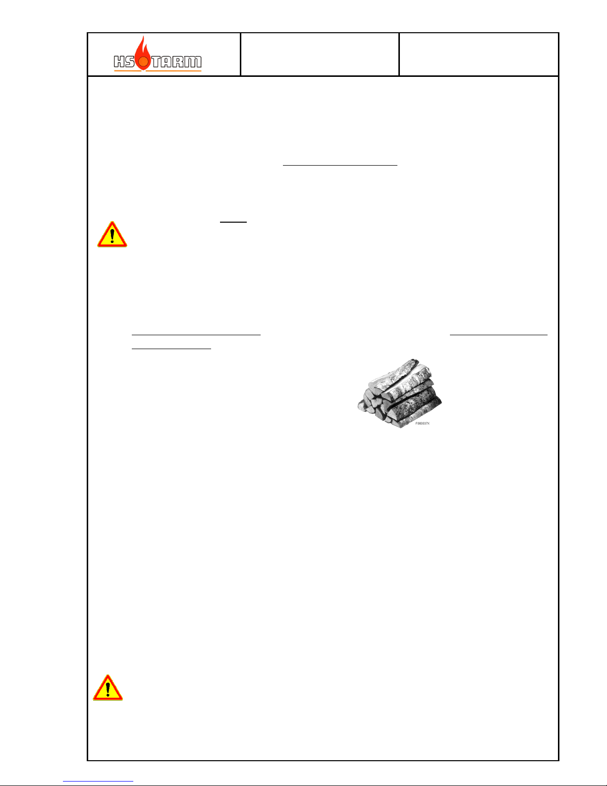
HK boilers are heating boilers, which use wood logs of forest wood. Almost all types of
woods will do.
The wood must be dry - moisture content lower than 25 %. This ensures good function of the
boiler and sufficient power.
NB: using wood with a moisture content lower than 15 % requires attention; do adjust the
primary air setting lower than normal to avoid ignited gas reentry to the wood log
compartment, which will result in intermediate gas combustion in this place, i.e. jumping
combustion.
If such situation occurs – be very careful if opening the wood log-filling door: explosive
backfire out the door can occur.
Old wood, woodworm, or having been a long time in a humid place is not suitable; it results
in power loss and incomplete combustion.
The wood must be chopped (10 to 15 cm of maximum diameter) and sawn in the length of
burning chamber to ensure a good function of the boiler without power loss.
Logs of 50 cm
Chopping and sawing the forest wood makes the quickest and most efficient drying
process. Stock it immediately under shelter (well aired, outside or inside). It must be
storage approximately two and half years to dry. Otherwise, a minimum of 3 years of
storage is necessary.
Wood exposed for a long time to bad weather or ageing (over 6 years) loses calorific
power: The consummation increases and the power from the boiler decreases. The
combustion is incomplete (soot and blackish-brown).
The boiler construction is not designed to work with treated wood from carpenters
workshops or industrial waste; a bad function will result as well as premature deterioration
of the boilers and their components.
1.3.2 Before the first use:
- Check the electronic and hydraulic connections.
- Purge the installation and check the pressure in the installation.
NEVER START THE BOILER WITHOUT WATER FILLING!
Page 8

MANUAL
HK2 – HK4 25-08-2014
Page
8
1.3.3 First and regular use
Before beginning, assure the good fitting of the suction fan, of its electrical supply, of the good
fitting of the combustion tunnel and the good setting of the primary and secondary air inlets.
1. Switch on the boiler - (F) to "1". Make sure that the lower door is closed and secured (locking
screw). Load a little amount of paper, small pieces of kindle wood, in sufficient quantity and
again some papers on top, then light them up.
2. Turn on immediately the suction fan by pressing the (D) button.
Start from cold boiler (actual flue gas temperature < minimum flue gas temperature) will
boost the fan speed until the timeout has passed or the minimum flue gas temperature is
reached – see parameter list in paragraph 3.9.
The air needed for combustion is already here, the fire starts very fast. Let the loading door a
bit open to ensure enough air for the ignition of the kindle wood (1 to 3 minutes, stay ahead
to watch)
3. The combustion has well ignited and a small bed of embers has formed. Open the upper
door with care: only a few centimeters first for a couple of seconds. Then load 3 to 4 thin
logs, then the necessary quantity of wood and reclose the loading door.
4. At the first use or in case of a change in the type of wood: as the boiler water gets hot
(>65°C): fine tune / adjust the primary and secondary air according to the table of paragraph
1.3.4, then fine tune the secondary air with the help of three figures shown on paragraph
1.3.5 while looking through the sight glass of the ash-discharge door in front of the tunnel. If
the inspection glass is dirty, unscrew the lid and clean the glass with the aid of a scouring
sponge.
The air adjustments need no longer to be modified, except in case of changing the
characteristics of the fuel.
The other starting operations are carried out at each new heating.
NOTE :
If pressing the fan button for more than 2 seconds as the fan is already running and the boiler is not
any longer in the start phase the fan will speed up for 5 minutes. This function is used for refilling the
wood log chamber for continuous combustion. The extra fan speed is used to both make the flue gas
by-pass more efficient and to re-start the combustion.
A
B
C
D
E
F
Page 9

MANUAL
HK2 – HK4 25-08-2014
Page
9
1.3.4 Primary and secondary air settings
In connection with the first start-up of the boiler, it is recommendable to make an emission test.
This procedure is in some countries regulated by law. To assure the correct procedure – ask the local
chimneysweeper for guidance.
1.3.5 Fine tuning of the secondary air
1.3.6 Minimum flue gas temperature setting, only for installer or advertised user.
The sensor is placed in sensor pocket in the fan housing (on the top of the body, at the back
left) and measures the flue gas temperature (factory setting to 90°C).
It is when this temperature goes down that the suction fan cuts itself off definitively when
there is no longer any wood in the boiler and the temperature of the flue gas decreases. This
to avoid unnecessary cooling down from airflow through the boiler.
1.3.7 Boiler temperature setting, only for installer or advertised user.
The normal temperature of the boiler is at least 85°C (factory setting 87°C). With the
« recyclable Kit D 60°C », an optional supply, the temperature of the boiler will stabilize at
about 62°C/65°C, as long as the boiler is in phase with storage tanks load. When the storage
tanks are loaded at least at 60°C at the lowest point, the boiler temperature will increase like
the storage tanks until the adjusted temperature.
Good setting. The flame
« just » leaves the
furnace, yellow and light
blue-tinged.
Too much secondary air.
The flame is too short and
blue-tinged: reduce the
secondary air.
Not enough secondary air.
The flame is too long and
orange / reddish: increase
the secondary air
Basic air settings
Primary air (high)
indication 3
Secondary air (low)
indication 4
Leafy trees/deciduous 30% 70%
Softwoods/evergreen 50% 40%
Page 10
MANUAL
HK2 – HK4 25-08-2014
Page
10
The optimal adjustment will bring the boiler temperature just below the setting of the boiler
temperature set point as the fan stops; having the setting too low will bring the fan to stop
when the combustion is still active; this is an unwanted mode and will lead to soot and a
dirty boiler.
NOTICE: The temperature safety valve (the valve connected to the cooling coil) is starting to
open at about 95°C. Thus, it must be taken care not to set the boiler thermostat
to more than 87°C in order to avoid an untimely shutting down of the security.
1.3.8 Safety thermostat (STB) – situated on front left of controller
The thermostat switches off at 100°C and stops the electric supply of the suction fan. If this
happens, it is advisable to:
- Wait for the boiler to cool down to 75 °C.
- Unscrew the cap of the thermostat (situated on the front left to the controller), push the
little button, screw on the cap
- Use again the boiler as normal.
If this happens again, it is advisable to check the following points by your heating installer:
- Check the function of the safety thermostat.
- Check that the use of the boiler has been correct
- Check that the boilers hydraulic system is correct (recycling system in a good state...)
- Check the function of the temperature safety valve
- Check the function of the boiler temperature sensor.
- Check that the chimney draught is not too strong (draught stabilizer is in a good state and
well adjusted).
- Check if there is some power supply’s cuttings (main electrical supply)
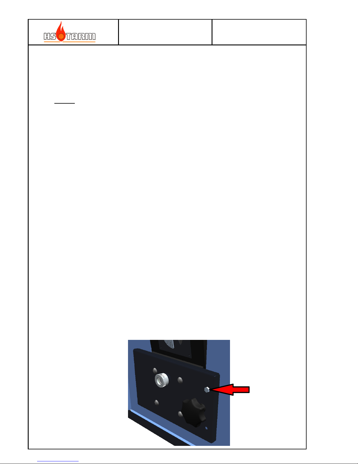
1.3.9 Ash door locking
The screw provided for this purpose shall be mounted as the boiler are in use (combustion is
going on). Remove the screw only if the boiler is cold (no combustion).
Page 11

MANUAL
HK2 – HK4 25-08-2014
Page
11
1.3.10 Fuse
The fuse located on the front of the control panel is 3.15 A (∅ 5 mm × 20 mm).
It blows if overload appears – replace only with an equivalent. Contact an electrician if the
fuse blows frequently.
1.3.11 Quick break down search (considering that the hydraulic attachment is correct)
Case 1: The boiler works, but the temperature does not increase properly:
Or: The temperature increases but the storage tanks heat up with difficulty and the heating
is weak.
- Check the air settings (open the primary air valve as necessary).
- Check if the heat exchange pipes, the loading chamber and the combustion tunnel are
clean (see 1.3.12 Cleaning and maintenance).
- Check if the primary air exit in the chamber (in front of you, behind the hanging plates,
just above stones) is cleared. Too great a layer of ash may be found in the burning
chamber, a more regular cleaning is required. After a few working years, a complete
cleaning of air ducts may prove useful: take out the air valves situated between the two
doors and clean all the ducts.
- Check if the door seals, the hatches for ash removal are waterproof. A bad
waterproofness leads to an external unwanted air intake away from the combustion
which leads to a loss of power and a bad function.
- Check the condition of the suction fan blade coupled to the motor (see 1.3.12 Clean and
maintenance).
- Check the temperature of the flue gas: it must be in the range of 130°C to 150°C. If it is
too low, the wood is probably not suitable. Try with a different type of wood or different
stock.
- Have the moisture content in the wood controlled with the help of a hygrometer (by
your installer).
- Check the good hydraulic connection, in good equilibrium (heat pump(s))...
Case 2: The boiler temperature increases but does not emit energy:
- Check the good function of the recycling pump.
- In the case of a "recyclable Kit D 60°C", check the openings of stop flaps and the
condition of the thermostatic cartridge, the heat pump motor (these components are
available as separate parts).
Case 3: The boiler stops when the wood is not consumed and the storage tanks are not loaded:
- The minimum flue gas temperature is incorrectly set (the base adjustment is around
90°C), its sensor is not in its place, or it is defective (A4 alarm).
- The wood may be too long, too wet, or in a bad position in the burning chamber: the
wood stays trapped, and does not subside during the combustion and it goes down until
there is no significant power, and the temperature of the flue gas decreases below the
minimum setting.
-
The combustion stifles by a lack of ash sweeping in the burning chamber or in the tunnel
or behind the tunnel, the power is lacking, the temperature decreases below the
minimum setting (H).
- The wood is wet and the temperature of the flue gas is too weak (no power).
Page 12
MANUAL
HK2 – HK4 25-08-2014
Page
12
Case 4: The suction fan never stops even after that the wood is burned:
- The minimum flue gas temperature is set too low (the temperature of the flue gas does
not decrease/not quickly enough below the setting) or too high (the flue gas
temperature must become more than 15 °C above the setting). Or its sensor is not in its
place or it is defective (A4 alarm).
Case 5: Nothing happens when you push the START button
- Check if the power supply for the controller is active.
- Make sure that the boiler is not too hot to begin heating again (shall be well below the
adjusted setting of (F).
- Check the fuse in the panel.
- Call your heating installer.
1.3.12 Cleaning and regular maintenance
The regular maintenance (cleaning) is the responsibility of the user. An annual control by a
professional is necessary according to current regulation.
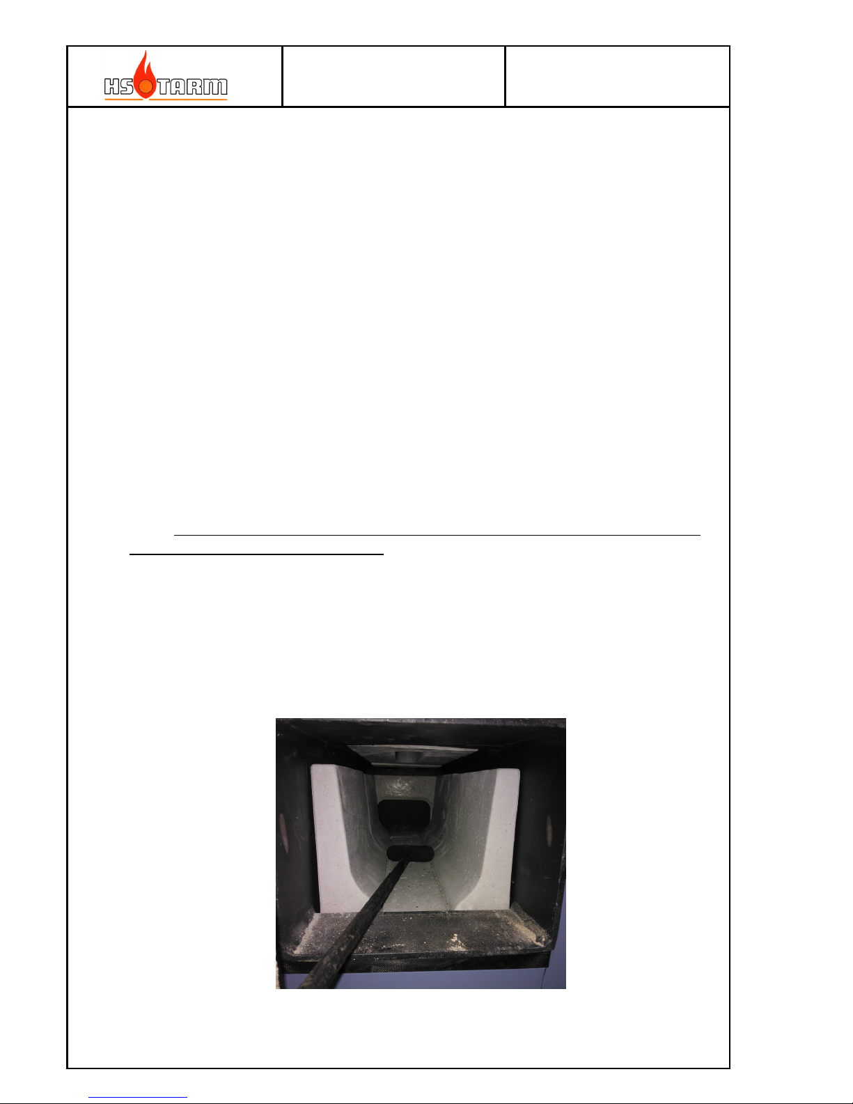
A metallic brush with an elbowed handle and an external ashtray are supplied with the
boiler. The ashtray is placed at the outside in front of the boiler and the nose slides under
the lower door, see the following photo:
Combustion tunnel ceramics – to be cleaned daily
Page 13
MANUAL
HK2 – HK4 25-08-2014
Page
13
a a) Ash sweeping of the burning chamber, checking of the primary air exits
Ash sweeping of the burning chamber (do not let it build up in the corners) is done when the
layer of ash reaches 3 to 5 cm. An ash sweeping may of course be done earlier. The quantity
of ash produced depends on the type of wood used, its age, its general quality, its moisture
content, of the consummation. A bad combustion produces a large buildup of ash and tar
(see 1.4). It is necessary 2 to 3 times per year to take out the hanging plates from the
burning chamber before sweeping at the sides and cleaning out the air passages. Neglected
maintenance can provoke premature wear and tear of ceramic, irreparable deformation of
the hanging plates, a premature wear and tear of the tunnel, an excessive clogging up.
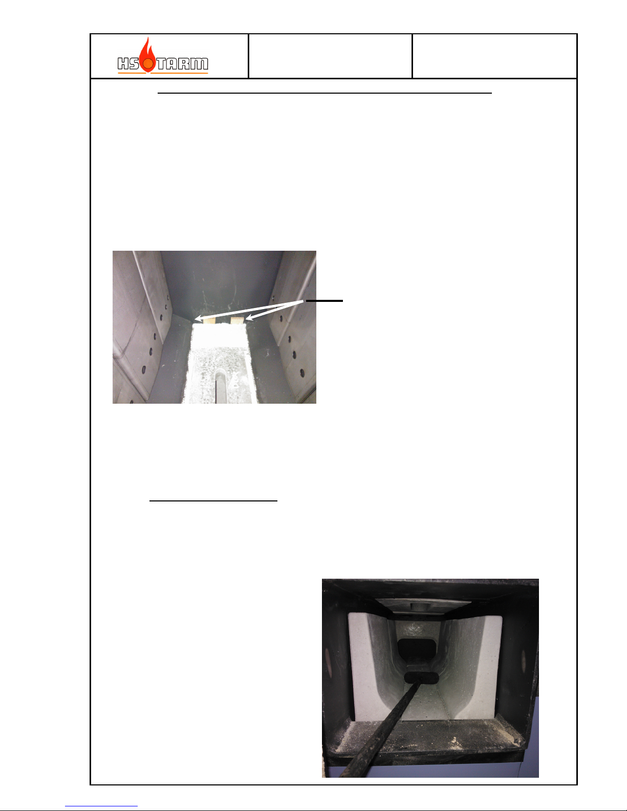
b) Ash sweeping of the tunnel
The ash sweeping of the tunnel must be done regularly (daily in winter): it must not be
obstructed by ash in order that the combustion can take place normally and the tunnel does
not overheat. Neglected maintenance can provoke irreparable deformation and a premature
wear and tear of the tunnel.
Do not remove the ceramics
for cleaning !!
Daily cleaning of the tunnel
Particular attention must be
given to cleaning the back
and front corners.
Page 14
MANUAL
HK2 – HK4 25-08-2014
Page
14
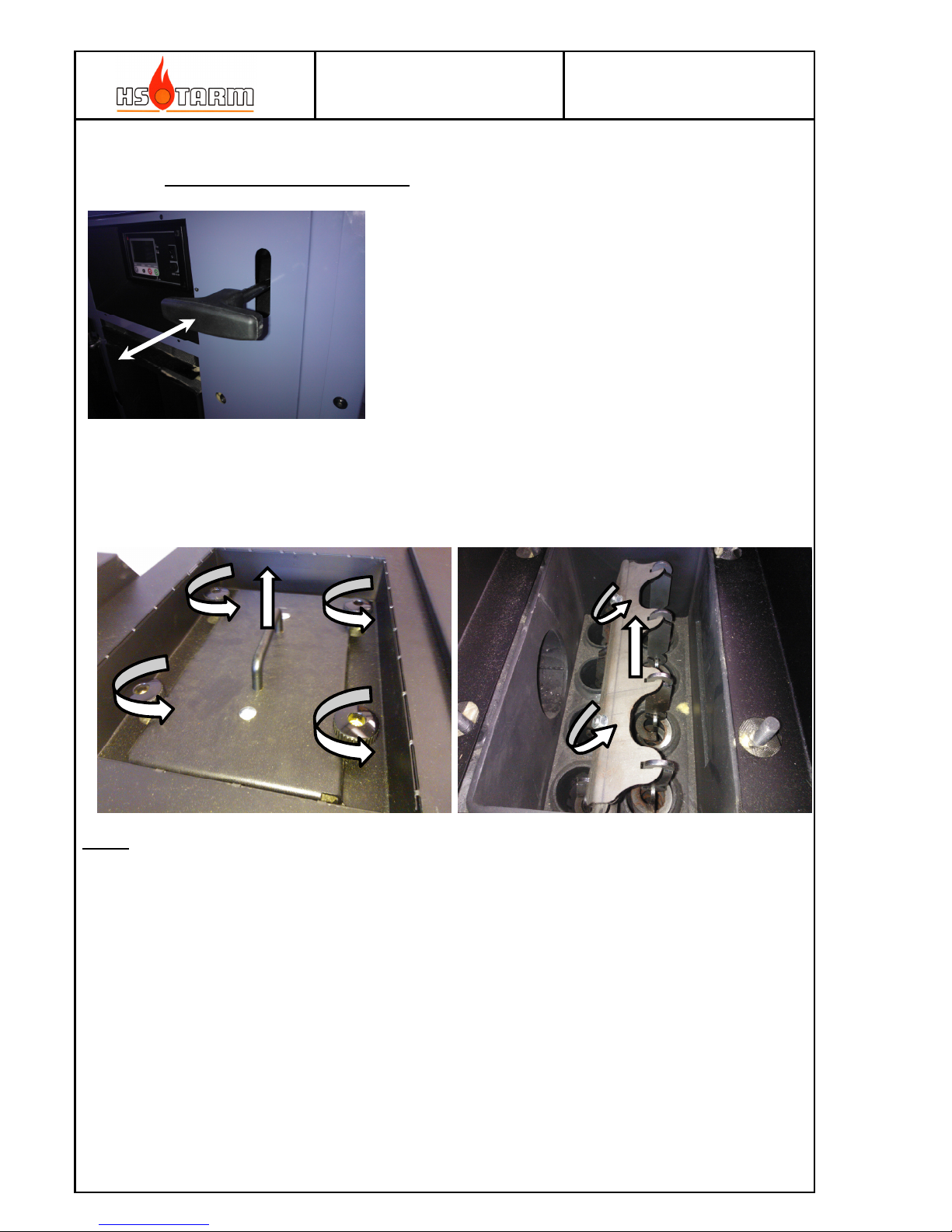
c) Cleaning the heat exchanger pipes
Notice: A poor quality fuel (too old, in decomposition phase, too much moisture..., will cause tar
deposits on tubes (incomplete combustion), with for consequence the difficulty to
remove the turbulators. A more frequently cleaning have to be done and a better fuel
shall be used as soon as possible.
1.3.13 Door silicone gaskets
After a few weeks of use, it might be necessary to re-tighten the loading and ash doors by
adjusting the hinge screws. The seal (a silicon covered glass robe) squeezes during the first
uses. Its waterproofness though guarantees the good function of the boiler. A nonwaterproof seal will harden and will have to be changed more often.
The rotating door handle makes a dynamic correction, which will ensure correct tightness as
compression of the robe after the first continues at smaller pace.
See the chapter on installation for the method and / or contact your heating-engineer.
The heat exchanger pipes are the principal
recuperation of energy. Located at the end of the flue
gas circuit, they will accumulate a little ash and soot.
Nevertheless, to conserve an optimum efficiency of the
boiler and good function, it is necessary to clean them
regularly. Having the boiler switched off manipulate
the handle in the front upper right corner. Make it a
habit every time before the boiler starts.
In the event of a sudden polluted boiler, it can be
necessary to make a more thorough cleaning of the
pipes. Open the access cover, take out the turbulators
and brush all the sides and each pipe from low to high
many times. Remounting and centering the cover and
take care to the mounting side.
Page 15
MANUAL
HK2 – HK4 25-08-2014
Page
15
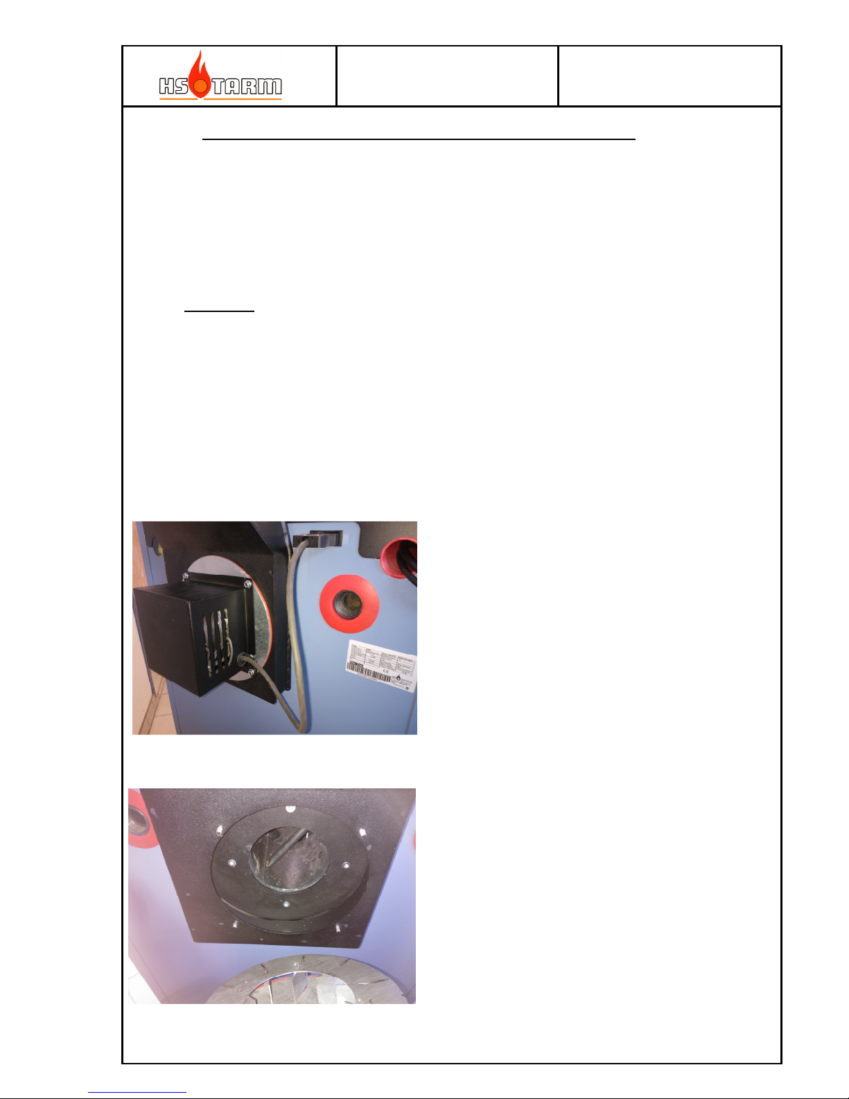
e) Cleaning of the suction fan, of its location, of the lower ash collector
This must be done with a periodicity that will depend of the boilers use (amount of wood
consummation): at least 2 to 3 times per year or at least all the 13 cubic meter of wood.
Check the sealing of the silicon gasket; it must be replaced immediately if it does not work
properly.
Procedure:
Before anything else switch of the power supply.
1) Unplug the fans electrical supply
2) Unscrew the four nuts holding both the fan protection cover and the fan itself.
3) Remove fan cover and fan
4) Clean the turbine
5) Clean the internal of the fan housing
6) Clean the flue gas sensor pipe and the flue gas outlet itself
Page 16
MANUAL
HK2 – HK4 25-08-2014
Page
16
f) Regular adjustments
The user must imperatively keep watch on the installation and the instruments of the boiler,
and ensure regularly that there is no external leak, especially on the joints of the boiler
(thermic discharge security valve, water flow and return, the glove pipe, drainage, join to the
water tank...)
All leaks shall immediately be stopped. External leaks are not covered by the factory
guarantee.
g) Maintenance of storage tanks with domestic hot water built-in tank
Our domestic hot water storage tanks are coated enameled steel and needs an annual
revision of their protective magnesium anode. This must imperatively be replaced if
necessary. The storage tanks equipped with an inspection hatch can be maintained internally
(descaling for example) when it is necessary (requires a new gasket)
1.3.14 Wear and tear of the refractory material, hanging plates and seals
The refractory material, metallic tunnel, hanging plates, and the seals are pieces/items
which will be under wear and tear during the lifespan of the boiler, according to different
types of woods, greater or lesser use of the boiler, the maintenance quality of the boiler.
This is perfectly normal and these pieces/items must be replaced, only when they are not
fulfilling their functions.
Generally, a crack or crumbling would not justify being replaced, when they are still doing
their job.
The removable hanging plates positioned in the burning chamber are equally submitted to
high temperatures and can be deformed or altered over time. To limit their normal wear and
tear we must avoid accumulating a large bed of cinders, leaving the cinders to consume for a
long time before reloading with fuel.
When loading the fuel, never "throw" the logs in the burning chamber, but place them
"gently". The refractories are sensitive to shocks and more particularly to heat.
A poor operation of the boiler (not enough evacuated energy of the boiler = slowing
down) provokes premature wear and tear of the refractories, the seals and the removable
hanging plates. See the start of directions for proper use
The boiler must never in any case be installed in a wet atmosphere.
Page 17
MANUAL
HK2 – HK4 25-08-2014
Page
17
2 Extra available accessories
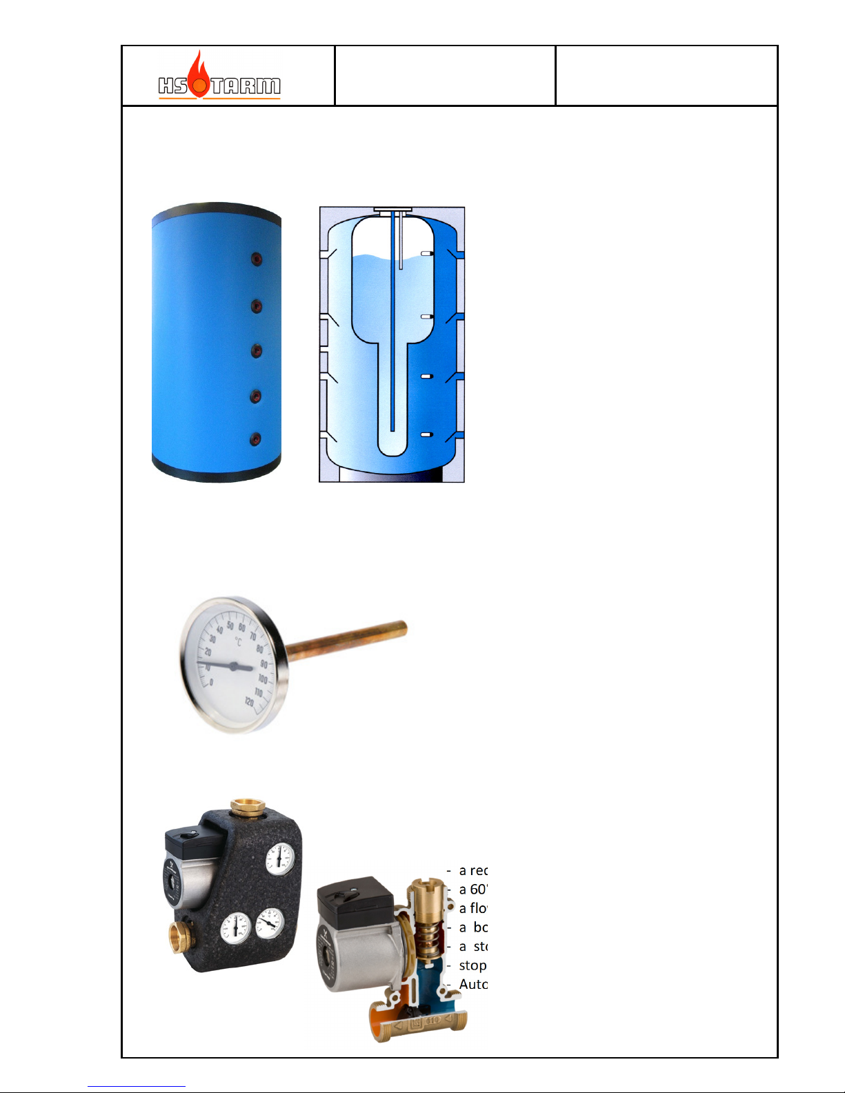
2.1 Storage tanks
2.2 Long sensor thermometer 150mm
2.3 Hydraulic Recycling Kit D 60°C
With a circular and insulated
mantle, finishing rosettes,
white colored.
There exist different models
of storage tanks:
Ask for the specific
documentation
This kit includes:
- a recycling circulator
- a 60°C thermostatic cartridge
- a flow thermometer
- a boiler return thermometer
- a storage tank return thermometer
-
stopping flaps
- Automatic balancing valve
For a good use of the boiler the storage
tanks must be obligatory equipped with 4
long sensor thermometers. They have a
large diameter (easy vision), glove tube
and glass protection equipped.
Page 18
MANUAL
HK2 – HK4 25-08-2014
Page
18
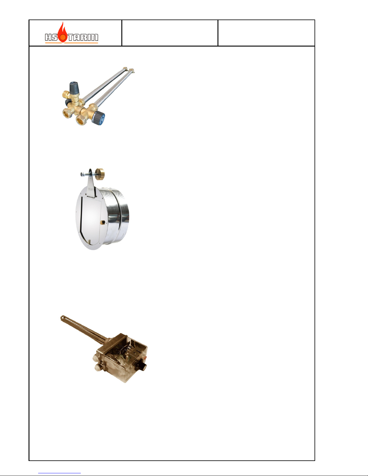
2.4 Domestic Hot Water Kit
2.5 Draught regulator
2.6 Electric heater
Allows in addition to the
security group to mix the
domestic hot water from 38°C
to 65°C (important when
double boiler storage tank
reaches 85°C). The current
regulation impose this type of
equipment
Its function is to stabilize the chimney
pressure. It is an indispensable accessory
for a boiler with solid fuel.
This model is in stainless steel and is
extremely effective because of its
balancing precision. It is balanced by a
brass counter weight, adjustable.
This heating resistance can be connected to
230/240V or 380/400v 3 phase power supply,
and got this own security thermostat for
overheating and an adjustable thermostat with
a frost-protection position.
It’s available in 4.5 Kw (3 x 1.5 kW) or in 6
kW (3 x 2 kW).
This accessory allow to maintain the
installation’s frost protection and for the
domestic hot water production out of the
heating period.
Page 19
MANUAL
HK2 – HK4 25-08-2014
Page
19
3 Installation instructions
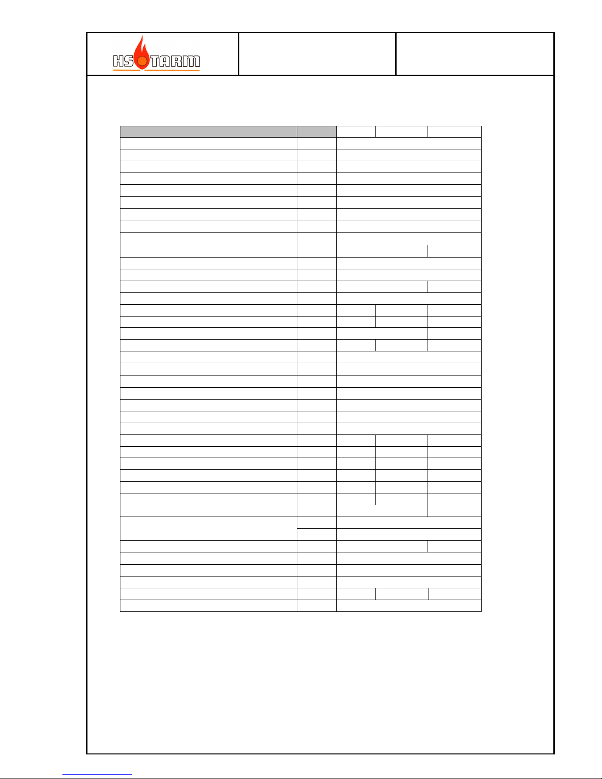
3.1 Technical data
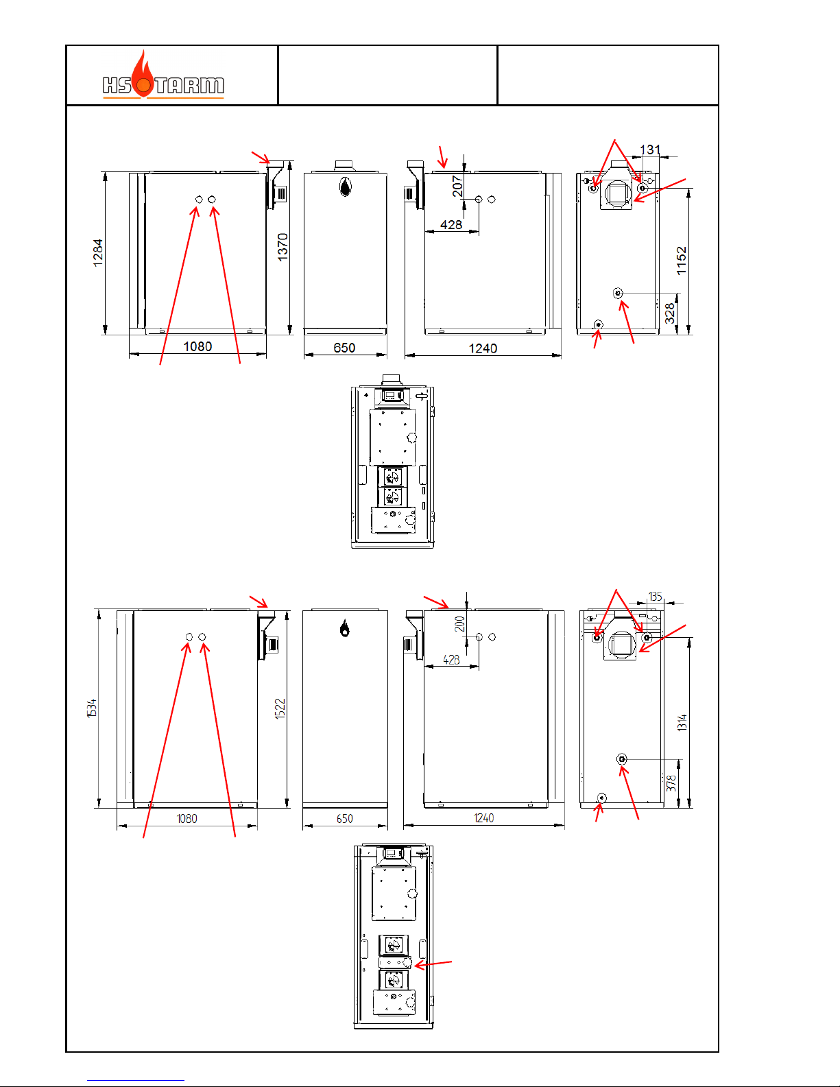
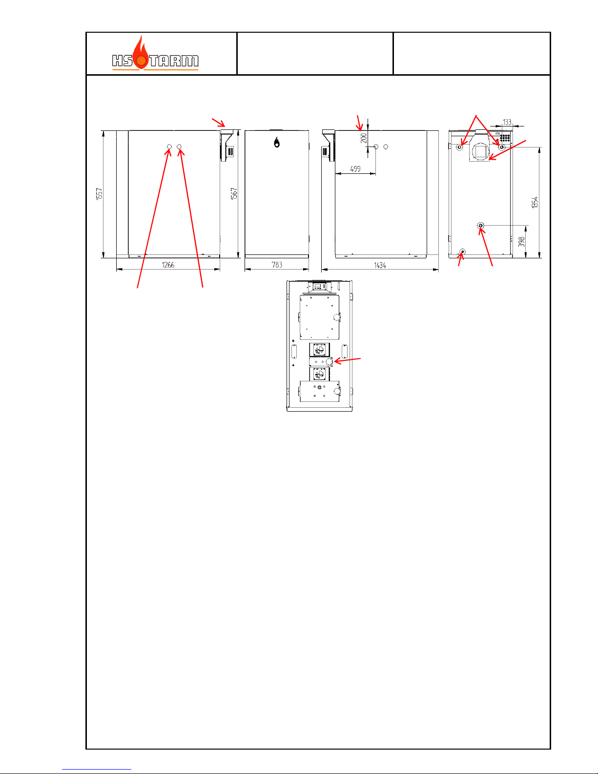
See dimensional drawings next pages.
HK2 HK3 HK4
(1) Flow connection "
1
(2) Return connection "
1
Power supply Volt
230
(3) Soot hatch -
X
(4) Boiler drainage "
1/2
(5) ∅ ext. flue gas pipe
mm
129
(6) Fan ∅
mm
180
Flue gas sensor pocket mm
7
(7) Cooling coil hole diameter
"
1
Cooling coil length
mm
380 500
(8) Safety valve sensor placement "
1/2
Stud for boiler water side sensor pocket "
1/2
Nominal power kW
32 50
Wood log chamber length mm
540
Comb. period hard wood h 3.5 – 4.0
4.5 – 5.5
4.0 – 5.0
Comb. period soft wood h 2.5 – 3.5
3.5 – 4.5
3.0 – 4.0
Loading door : w. / h. mm
250/340 330/420
Wood log chamber volume (net) l
110
150
200
Wood logs length - max cm
50
∅ hard wood max diameter
cm
10-15
∅ soft wood max diameter
cm
10-15
Max service pressure bar
3.0
Boiler production test pressure bar
4.5
Cooling coil test pressure bar
25
Max operating temperature °C
100
Total empty weight kg
505
615
822
Water capacity l
120
140
270
Minimum storage tank volume l
1250
1750
2250
Dusts 10 % O2 mg/m
3
45 30
<60
CO 10 % O2 mg/m
3
677
612
<700
OGC 10 % O2 mg/m
3
28
28
<30
Nominal flue gas temperature °C
130 <160
Minimum draught needed mm WC
1-1,5
Pa
10-15
Mass flow of flue gas g/s
20 33
Pressure loss ∆T 20°C
mmWC
3,5
Pressure loss ∆T 10°C
mmWC
14
Electric consumption W
<70
Efficiency %
91.6
92,7
>90
Boiler class EN 303.5 2012 Class
5
Page 20
MANUAL
HK2 – HK4 25-08-2014
Page
20
HK2 (Bonus 30 MK2, Boréale, Excellent 30, Bonus 30)
HK3 (Solo Innova 30 MK2, Fjord 30, Excellent 40, Solo Plus 30)
(1)
(1)
(2)
(2)
(3)
(3)
(4)
(4)
(5)
(5)
(6)
(6)
(7)
(7)
(8)
(8)
Ignition door (HK3 and
HK4 only)
Page 21
MANUAL
HK2 – HK4 25-08-2014
Page
21
HK4 (Solo Innova 50 MK2, Fjord 50, Excellent 50, Solo Plus 50)
Ignition door (HK3 and
HK4 only)
(8)
(7)
(5)
(3)
(1)
(6)
(4)
(2)
Page 22
MANUAL
HK2 – HK4 25-08-2014
Page
22
3.2 Chimney and flue gas pipes characteristics
This must conform to local regulations.
It is characterized by its draught, which is the low pressure maintained at the chimney duct
at the inlet of flue gasses from the boiler. The principal characteristics for a chimney to be
correct are the following:
2 Sufficient height, appropriate and constant section
3 Outlet exceed the roof’s ridgepole at least 40 cm
4 Excellent vacuum sealing (no cracks, soot hatches close correctly)
5 Excellent isolation especially in the cold parts (no inflammable material)
6 No communication between a neighboring chimney
7 Cleanliness (periodic sweeping). A chimney used with wood combustion shall be swept
at least to 2 to 3 times per year – here local requirements shall be followed.
8 A rectilinear profile.
9 Inspection hatches at least after each flue gas pipe bend and after 1,5m of straight
length.
Flue gas pipes diameter and minimum chimney diameter: Ø130 mm – Ø150 mm
The temperature of the flue gas could sometimes be very low – e.g. during startup. As these
flue gases are loaded with water steam produced in the wood burning process, often
condensation arises inside the chimney – dependent of degree of insulation of the chimney.
Therefore the chimney must be designed to allow condensation on the internal walls.
Wood burning produces non-negligible quantity of water steam. This results in the
combination of oxygen / hydrogen during the burning, the moisture of the heated air and
the hygrometry of the wood.
On average: 1 kg of wood, which has a moisture content of 25 %, will produce 0.7 kg of
water in form of steam.
The temperature of condensation of the water steam contained in the flue gas comes when
the combustion of the wood is at 60°C. If the temperature of the internal wall of the flue gas
pipes is inferior to the condensation temperature, there is a buildup of condensate resulting
in the risk of having a back flow into the boiler body, which can lead to severe corrosion.
This physical phenomenon clearly shows that good chimney isolation is necessary.
In the case of an existing chimney where the renovation and isolation are practically
impossible or in the case of a strong section of chimney (old open fire or open chimney) an
internal pipe should be an efficient solution.
All flue gas pipes, joined flue gas pipes, flue gas pipes, must have a technical specification or
approval; equally refer to the rules for the health and safety as defined specifically for your
region.
Page 23
MANUAL
HK2 – HK4 25-08-2014
Page
23
3.3 Connecting the boiler to the chimney
The boiler must be installed as close as possible to the chimney.
A long length of flue gas piping must - if possible - be avoided and as well more bends which
reduces draught and facilitates the formation of condensate.
The condensate must under no circumstances flow into the boiler.
Use the bends or the straight length with an inspection and soot hatch.
Ensure that the vacuum sealed interlocking pieces are good. If not - use ceramic/glass fiber
seal and/or refractory mastic (according to the technical possibilities of the chimney and the
regulations).
The isolation of the flue gas piping and the connecting flue gas pipes is strongly
recommended.
3.4 Draught (lifting force)
To ensure a good operation of the HK boilers, the pressure of the chimney measured at the
boiler duct shall be between 0.5 and 1.5 mm of water column negative pressure and be
perfectly stable.
It is measured with a pressure meter (for example in liquid) with boiler at raised
temperature (> to 70°C): in cool weather and in normal function.
If the draught is too weak, the evacuation of combustible gas will be insufficient.
If the draught is too strong, the combustion is increases and the flue gas temperature raises thereby wasting the fuel. Moreover, the boiler risks over-heating and premature wear of the
hanging plates can appear.
To have a stabilized pressure in the chimney with an HK boiler, it is imperative to install on
the pipe, a stabilizer or suction moderator.
The conditions of installation of the stabilizer:
- The diameter of the stabilizer shall be at least equal the flue gas pipe. It shall be installed
as close as possible to the boiler. Its setting shall be done with a pressure meter.
- If, at the maximum setting (the stabilizer’s shutter is wide open), the pressure is always
superior to the 1.5 mm of the water column, and a second moderator must be installed.
Page 24
MANUAL
HK2 – HK4 25-08-2014
Page
24
3.5 Safety / Expansion
The HK boilers are a wood burning boiler and thus the filled in wood after ignition represent
a large amount of energy. The expansion system shall be conforming to relevant regulations.
The cooling coil delivered must be mounted via the thermal discharge valve.
It is forbidden to use an open expansion tank with this boiler.
a) Installation of a Under Pressure Expansion Tank :
- The usable capacity and the inflation pressure of the expansion tank shall be
coordinated with the volume of water of installation, at the static height of the installation
and at the maximum working temperature. The capacity shall be at minimum equal to 7 %
of the total volume of water in the installation. The dimensions shall conform to the
current regulations.
- The installation of the HK boiler in a pressurized system necessitates the use of a thermic
discharge cooling coil delivered with the boiler (anti-boiling exchanger), in connection with
a temperature safety valve of which the sensor is calibrated at 97°C. This unit assures the
cooling of the boiler in case of over-heating. The cold water pressure at the valve should be
at minimum of 2.0 bars.
- The installation of a safety valve ∅ 3/4 " preset to 3 bars maximum with manometer is
obligatory. It must comply with relevant regulations. It shall be installed at the top part of
the boiler without any obstructing materials for example closing valves either totally or
partially.
Our guarantee does not cover damages caused by pressure above 3 bars (see before),
defective valve or in case of false setting.
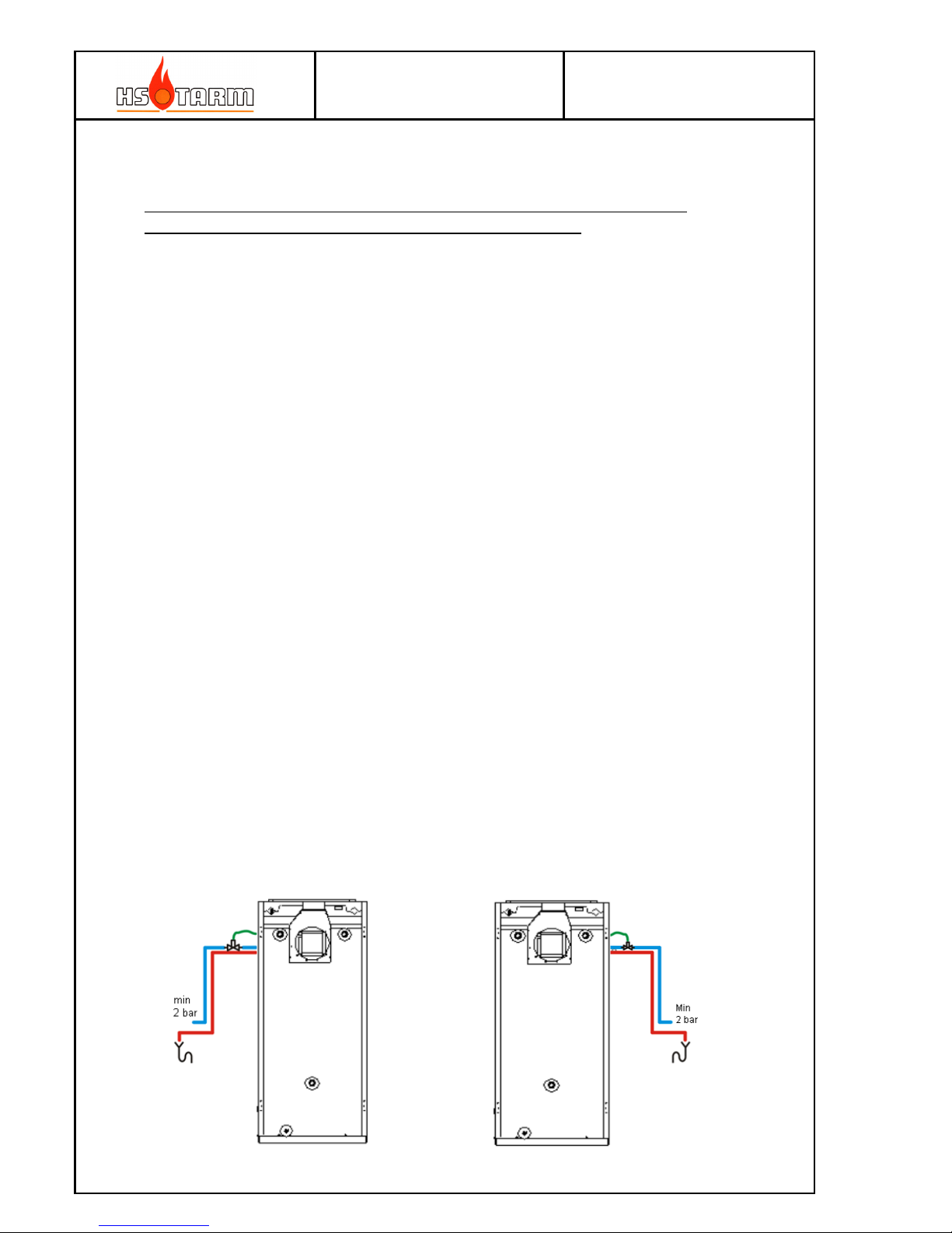
b) Connection of the safety cooling system
The cooling coil must be mounted in a way which gives an easy access to the upper and rear
cleanings hatches and to the suction fan’s turbine. Possible mounting ways for the cooling
coil: boilers left or right side (see the picture below).
The female plug with squared footprint can be unscrewed with the help of a 1/2" key or with
an 18mm x 18mm x 70 mm squared iron inserted inside, grasped with a claw pliers.
Right
Left
Page 25
MANUAL
HK2 – HK4 25-08-2014
Page
25
3.6 Adjustment of temperature settings, sensor location
The temperature settings are factory made and are normally not to alter. However, a control
of the factory settings before servicing is advisable and as well a sensor control.
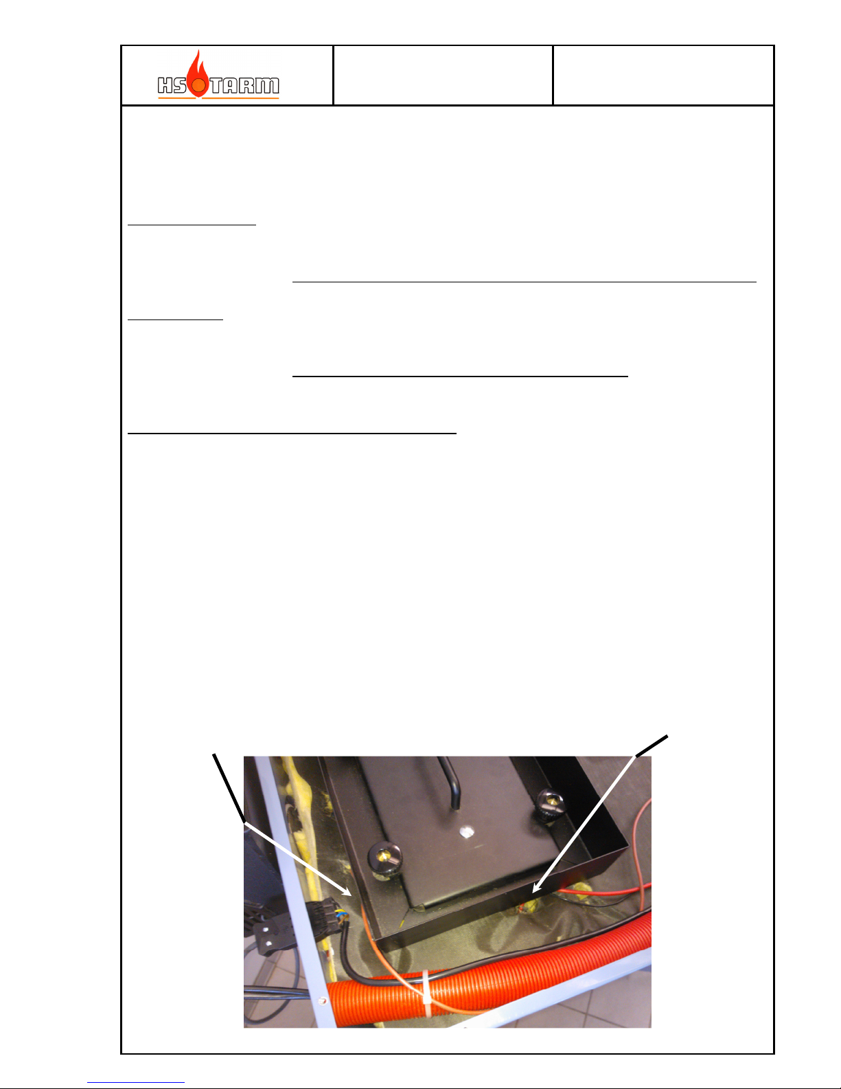
Boilers water sensor: The role is the same as a temperature-limiting thermostat. It stops the
suction fan before the safety thermostat or the hydraulic safety cooling
system is activated.
Boilers factory settings: 87°C (maximum position) – fan shuts out at 90 °C.
Flue gas sensor: The role is to stop the suction fan and recycling pump when the
combustion ends. The switch off happens when the flue gas temperature
decreases below the minimum flue gas setting value.
Minimum flue gas temperature factory setting: 90 °C.
In which case can an adjustment become necessary?
The boiler temperature can exceptionally decrease to 85°C, if at 90°C (of boiler water) either
the safety thermostat shots off the boiler and/or the temperature safety valve has already
began to open.
The amount of embers in the bottom of the loading chamber is insufficient after the fan has
stopped; the minimum flue gas temperature can be adjusted to make the amount of ember
sufficient for an easy startup for the next firing. In some cases (low fuel quality, chimneys
draught not easy to stabilize...) it can be useful to change the factory setting. Proceed like
below:
- When the suction fan stops: if there is no embers at all: set to 110 °C – 120 °C.
- When the suction fan stops, there is too much embers, covering the entire bottom of the
loading chamber: set 85°C, or 80°C.
Flue gas sensor Boilers sensor and STB
Page 26
MANUAL
HK2 – HK4 25-08-2014
Page
26
3.7 Boiler connections / storage tanks
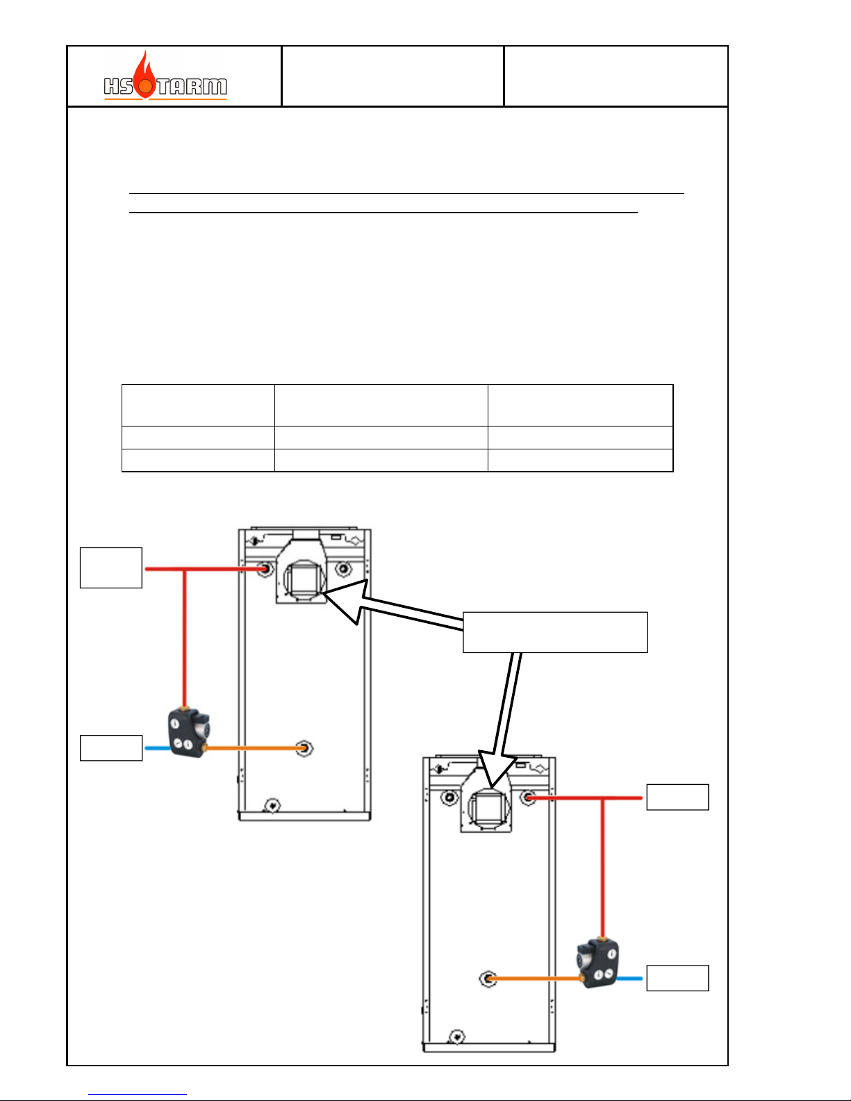
The boiler must be connected to an energy store through a recycling system having the
following function (this stipulation is obligatory in order to keep the guarantee):
- The circulation between the boiler and the heating implements (the energy store, the
storage tank, the heating installation...) must be absent as long as the boiler has not
reached the temperature of 60°C.
- When the circulation between the boiler and the heating implements is made, a
permanently controlled reheating to minimum 60°C is obligatory and is done by a by-pass
between the boiler flow and the return to the boiler (recycling).
Hydraulic connections to the boiler: preserve an easier access to care / maintenance
Boilers type Minimum required useful tank
volume
Advised useful tank
volume
HK2 1250 liters 1500 liters
HK3 2250 liters 2500 liters
Flow
outlet
Return
Flow
Return
Fan cleaning / maintenance
access
Page 27
MANUAL
HK2 – HK4 25-08-2014
Page
27
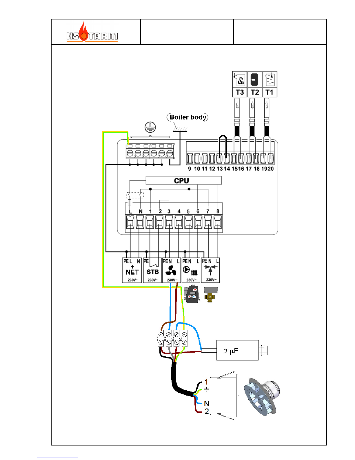
3.8 Electrical connections
Page 28
MANUAL
HK2 – HK4 25-08-2014
Page
28
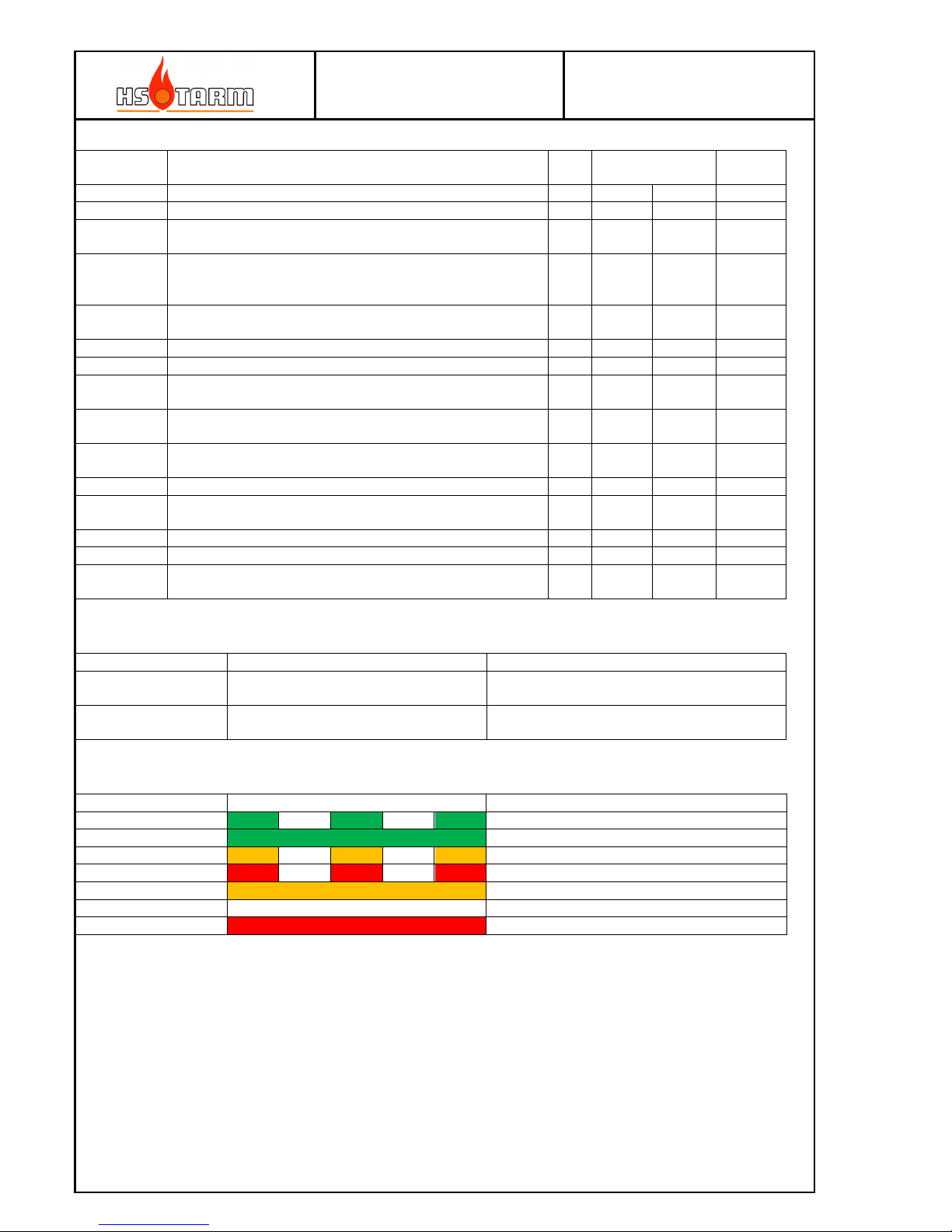
3.9 Controller parameters
Parameter
No.
What is? Unit Span
min max
Default
value
n0 n0 is the maximum fan speed under normal operation. % (n2+1) 100
40
n1 n1 is the minimum fan speed under normal operation. % 0 (n1-1)
30
n2 n2 is the temperature above which the pump is running during
combustion.
°C 0 80
58
n3 n3 is the temperature difference between boiler preset
temperature and restart after a stop of the fan from too high
boiler temperature.
°C 0 10
0
n4 n4 is the time after the flue gas temperature has become lower
than (n6) in which the fan continues to run.
min 0 255
0
n5 n5 is the display brightness level. % 0 75
50
n6 n6 is the minimum flue gas temperature °C 20 250
90
n7 n7 is the temperature below which the 230 VAC output for
the zone valve goes high
°C 0 80
40
n8 n8 is the temperature above (n7) at which the 230 VAC
output for the zone valve goes low
°C 1 20
5
n9 n9 is the extended running time for the boiler pump after the
fan has stopped
min 0 99
10
r0 r0 is the flue gas temperature hysteresis °C 10 20
15
r1 r1 is the firing up time, i.e. the maximum running time in
extended high speed (r2)
min 0 250
15
r2 r2 is the extended high speed % n0 100
80
r3 r3 is used to reset to factory settings - 0 1
0
r4 r4 is the reading temperature of the storage tank sensor °C - -
actual
value
3.10 Alarm codes
Alarm number Alarm explanation Comments
A2 Boiler temperature sensor disconnected
or damaged
The boiler cannot run in this state
A4 Flue gas temperature sensor
disconnected or damaged
The boiler cannot run in this state
3.11 Controller indications (function mode)
Controller state LED Display
Fire up Blinking boiler symbol
Normal operation Constant (still) display
Reduced output Fan indication reduses
High boiler temp. Blinking fan symbol
Burn out Constant (still) display
Normal stop Constant (still) display
Alarm AL2 or AL4 blinking
Page 29
MANUAL
HK2 – HK4 25-08-2014
Page
29
3.12 Controller function explanation
Boiler start:
Short press (< 2 sec):
Fire-up function activated; the fan runs at high speed (r2) until the flue gas temperature reaches the minimum flue gas
temperature (n6) or till the fire-up time (r1) has elapsed; hereafter the fan speed reduces to the max rotation speed (n0).
Pressing Stop button will stop the fan if and only if the flue gas temperature is below (n6).
The boiler symbol is blinking until the boiler has reached normal operation.
The LED is blinking green until activation of the normal operation mode.
Long press (> 2 sec):
Refill function activated; the fan runs at high speed (r2) for 5 minutes (fixed value).
NB: The refill function can only be activated if and only if the fan is already running and only if the fire-up function is
not activated.
The wood log symbol in the upper left corner of the display shows for as long as the Refill function is active.
Pressing the Stop button will deactivate the high speed (the wood log symbol will switch off); hereafter the fan speed will
continue at normal maximum speed (n0).
Pressing Stop button once more will stop the fan if and only if the flue gas temperature is below (n6).
The LED is blinking green if:
• Refill active, i.e. until the 5 minutes has passed.
• the Refill function has been stopped and the flue gas temperature < (n6+r0)
Operation:
Shifting to normal operation:
When the flue gas temperature comes above (n6) + (r0) the controller shifts to normal operation. First after reaching this
state, the fan will be able to stop again if the flue gas temperature decreases below minimum flue gas temperature (n6).
During normal operation, the speed of the fan maintains at max rotation (n0). Only if the boiler temperature rises above
the boiler temperature set point (preset boiler temperature) the fan speed reduces linearly towards min rotation speed
(n1) until the boiler temperature comes above (preset boiler temperature + P5 (under code 804)). If the boiler
temperature comes above this temperature the fan stops. The fan will only start again if the boiler temperature comes
below (preset boiler temperature – boiler temperature hysteresis (n3)).
During normal operation, the LED lights constant green.
During period with reduced fan speed, the LED lights constant orange.
If the fan stops because of high boiler temperature, the LED lights blinks red during this period.
IMPORTANT: As the flue gas temperature has come above the minimum flue gas temperature (n6), it is no longer
possible to stop the process using the STOP button.
Burning down:
Shifting to burning down period:
As the flue gas temperature during normal operation comes below (n6), the function shifts to the burning down function.
For the period “Detection time out of fuel” (n4) the fan continues to run.
Setting the parameter (n4) to zero (0) will stop the fan stops as the minimum flue gas temperature reaches (n6).
The LED is blinking orange during the burning down period.
Pressing the Stop button will stop the Burning down function, i.e. the fan stops, and the controller goes to the Finished
operation mode.
Finished operation:
As the burning down period has elapsed, the fan stops.
The pump continues to run for the time (n9) – if and only if the boiler temperature is above (n2).
The LED is OFF (no light)
Page 30

MANUAL
HK2 – HK4 25-08-2014
Page
30
Boiler pump operation:
The boiler pump will only run if the boiler is in operation. During finished operation the pump will never run.
Except if, the “extended work of CH pump...” parameter (n9) is set > 0; in this case, the pump runs for this time after the
fan has stopped – and if and only if the actual boiler temperature is above “Pump turn on temp.” (n2).
The boiler pump will only run as the boiler temperature is above the start temperature of the boiler pump (n2).
NB: bridging the room thermostat input is necessary. Otherwise the pump will run in an intermediate manor (On for a
time and off in a time).
3-way-valve function:
In correlation with the temperature measurement of the storage tank temperature the 3-way-valve output reacts like
this:
• As the temperature of the storage tank goes below the temperature of the shift zone valve parameter (n7>0) the
230 VAC output is activated
• As the temperature afterwards comes above the temperature of the shift zone valve + hysteresis of the shift
valve (n7+n8) the 230 VAC output is de-activated.
Stopping the fan:
Stopping the fan is only possible if the flue gas temperature is below (n6).
Power supply failure:
In the event of a failure in the power supply, the fan (and pump) will continue if and only if the flue gas temperature is
above (n6) as the power comes back.
Alarms:
In the case of an alarm (e.g. defect sensor), the LED lights constant red and the relevant alarm code shows in the display
Start and Stop buttons:
Activation by use of the green Start button is only possible in the standard display.
NB: Deactivation of functions by use of the red Stop button is only possible in the standard display.
F button:
Pressing one time shortly on the F button:
The boiler preset temperature is directly adjustable from the front (no code needed), but the adjustable span is only 8587 °C.
Boiler preset temperature:
Access: press F button shortly.
Adjust by red and green buttons.
Flue gas temperature:
Pressing the F button once more and the actual flue gas temperature shows in the display.
Press again and the display return to standard display.
Parameter list:
Access by pressing the F button for more than 3 seconds.
To gain access to the parameter lists a code is needed.
Parameters under the code: 111
Page 31
MANUAL
HK2 – HK4 25-08-2014
Page
31
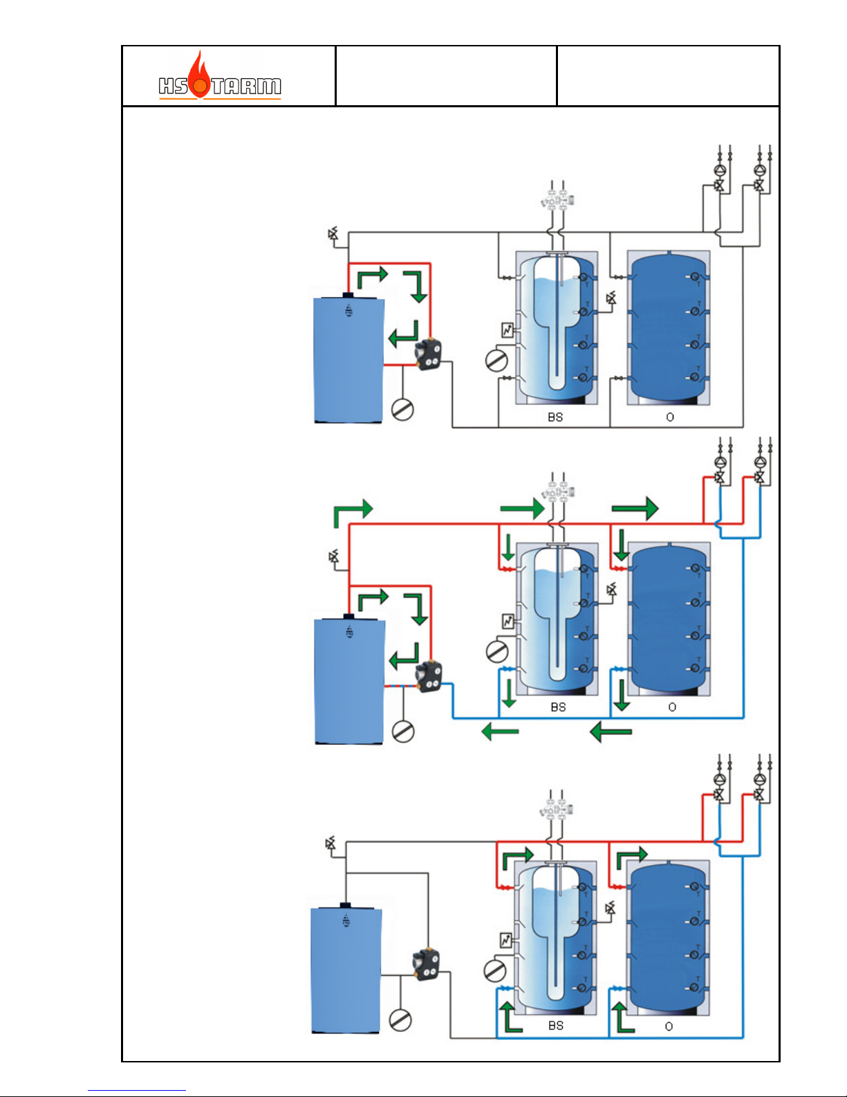
3.13 Main hydraulics
3.13.1 Principle of the hydraulic recycling
Temperature increasing
(100% recycling)
Burning phase with water
return heating.
Storage tank loading, from
the top to the bottom
System phase
Tank storage discharging,
from the bottom to the top.
Page 32
MANUAL
HK2 – HK4 25-08-2014
Page
32
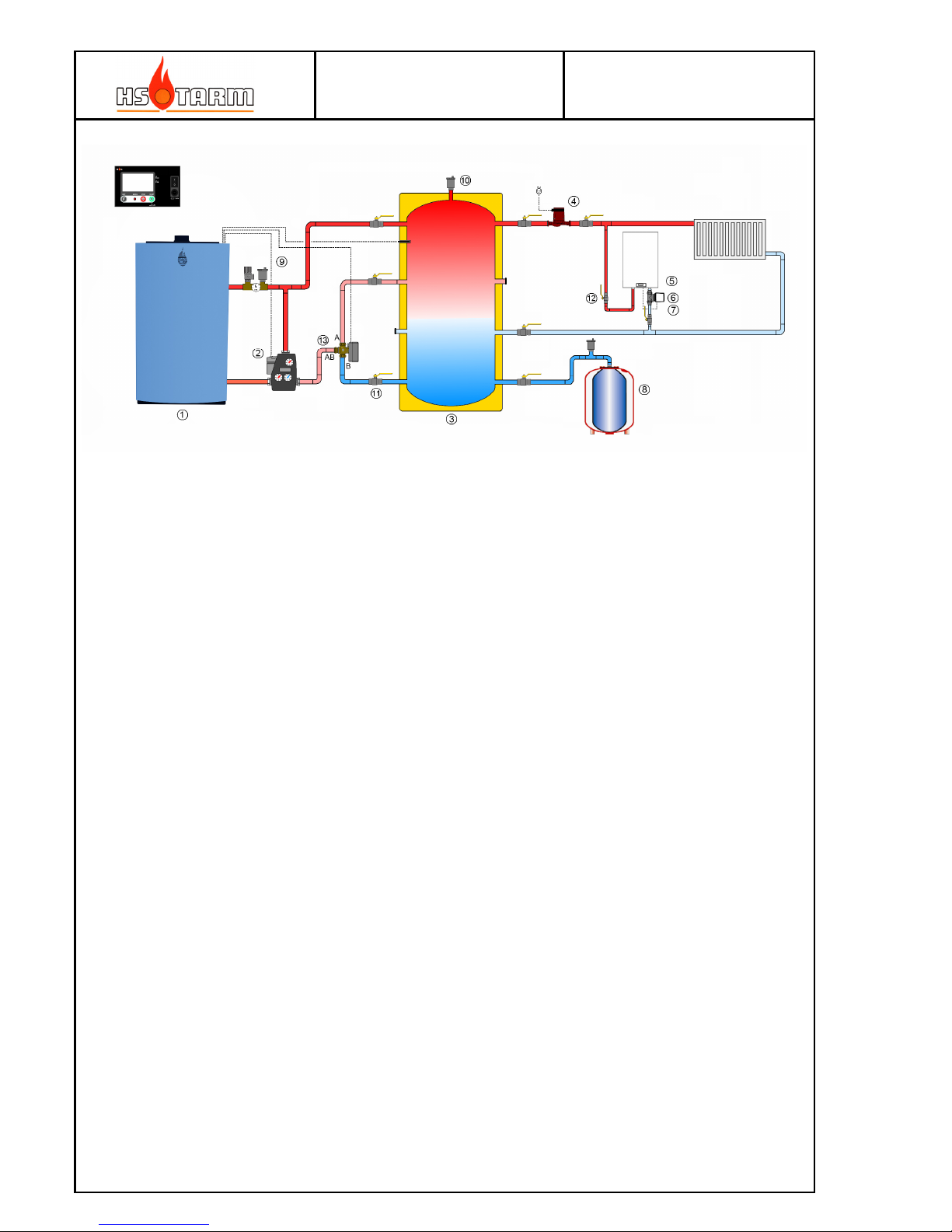
3.13.2 Installation diagram – simple system
1 : HK2/HK3
2 : Return temperature unit
3 : Storage tank O 1500 L/2500L
4 : System pump
5 : DHW tank
6 : Themostatic valve
7 : Thermostat
8 : Expansion vessel 150 L/200L
9 : Safety group
10: Automatic vent
11: 1” ON/OFF valve
12: ¾” ON/OFF valve
13 : 3-way valve – spring return
The purpose of the 3-way valve is to minimize the system volume as the heating system is requiring high energy input.
As the storage tank sensor measures a temperature below 40 °C the valve shifts to the top of the tank.
as the temperature in this position comes above 45 °C the valve shift to the bottom of the tank.
Both the shift up temperature (deafult 40 °C (n7)) and the hysteresis (default 5 °C (n8)) can be adjusted.
Page 33

MANUAL
HK2 – HK4 25-08-2014
Page
33
No text.
Page 34

MANUAL
HK2 – HK4 25-08-2014
Page
34
No text.
Page 35

MANUAL
HK2 – HK4 25-08-2014
Page
35
No text.
Page 36

MANUAL
HK2 – HK4 25-08-2014
Page
36
Rev. 02/010914
 Loading...