

Hsotram HK2, HK3, HK4 User Manual
MANUAL
HK2 – HK4 25-08-2014
Page
1
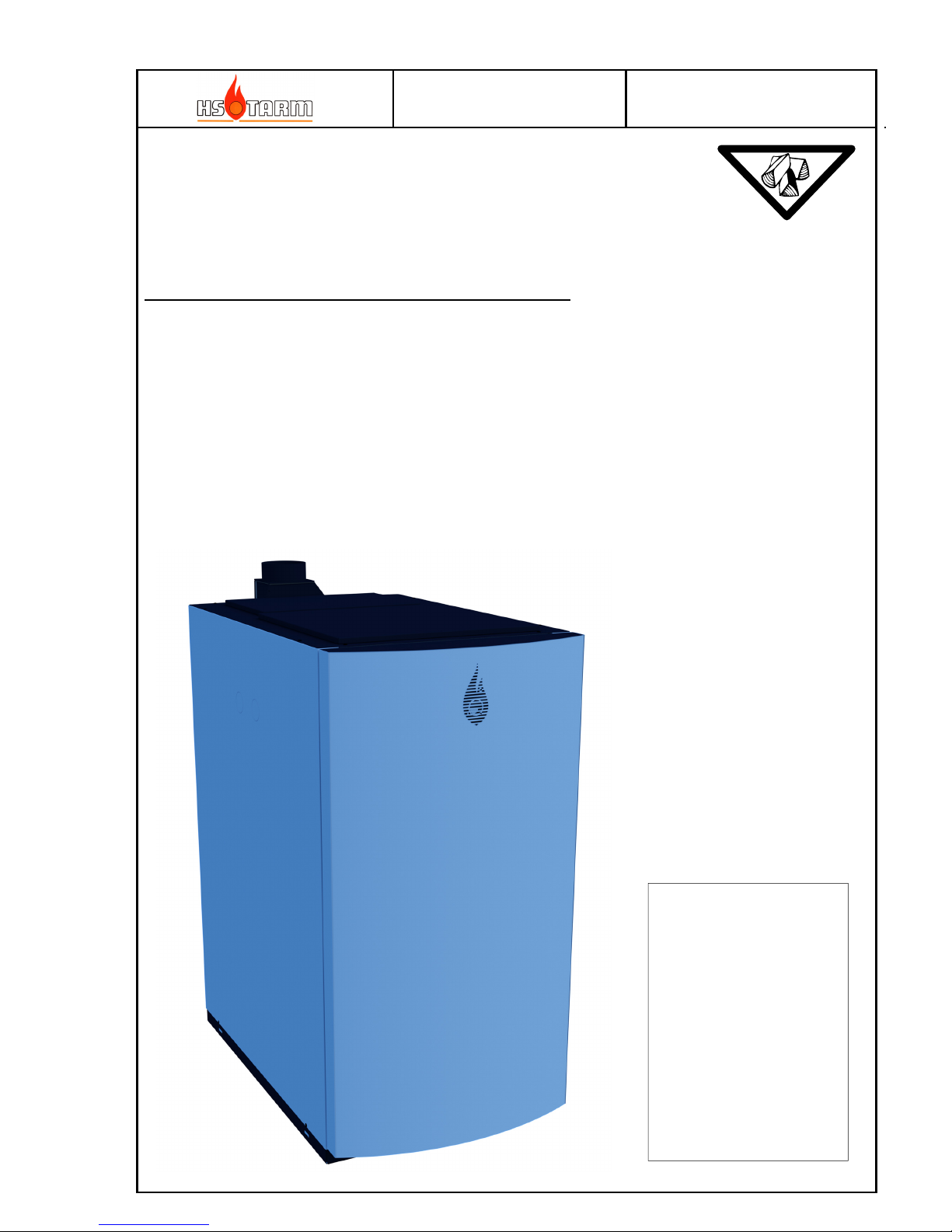
HK2, HK3, HK4 STD
(Bonus 30 MK2, Excellent 30, Boréale, Bonus 30, Solo Innova 30 MK2, Excellent 40,
Fjord 30, Solo Plus 30, Solo Innova 50 MK2, Excellent 50, Fjord 50 and Solo Plus 50)
Wood log central heating boilers
Chapter
User instructions and regular maintenance (1)
Extra and optional accessories available (2)
General conditions of sale and guarantee (3)
The product produced by HS
TARM A/S type:
HK2, HK3 and HK4
made according to:
• EMC Directive
(89/336/EEC incl.
modification 92/31/EEC
and 93/68/EEC)
• LV Directive 2006/95/EEC
• PE Directive 97/23/EEC
• Standard EN 303-5:2012
Efficiency class 5
Emissions class 5
MANUAL
HK2 – HK4 25-08-2014
Page
2
TABLE OF CONTENTS
The content of this manual is susceptible to modification by the manufacturer without notice.
Content
1
USER INSTRUCTIONS AND MAINTENANCE .................................................................................................3
1.1 D
ESCRIPTION OF THE HEATING BOILER AND CONTROL PANEL
......................................................................................3
1.1.1 Use of the heating boiler with storage tank (See page 3): ......................................................................................5
1.2 R
ESPONSIBILITY, SECURITY AND DUTY OF USER
..........................................................................................................6
1.2.1 Responsibility .........................................................................................................................................................6
1.2.2 Rules of safety .........................................................................................................................................................6
1.2.3 Duties of user..........................................................................................................................................................6
1.2.4 Local installation requirements ..............................................................................................................................6
1.3 G
ENERAL INSTRUCTIONS OF USE
.................................................................................................................................7
1.3.1 The wood, solid fuel ................................................................................................................................................7
1.3.2 Before the first use: ................................................................................................................................................7
1.3.3 First and regular use ..............................................................................................................................................8
1.3.4 Primary and secondary air settings ........................................................................................................................9
1.3.5 Fine tuning of the secondary air.............................................................................................................................9
1.3.6 Minimum flue gas temperature setting, only for installer or advertised user. ........................................................9
1.3.7 Boiler temperature setting, only for installer or advertised user. ..........................................................................9
1.3.8 Safety thermostat (STB) – situated on front left of controller ............................................................................... 10
1.3.9 Ash door locking ................................................................................................................................................... 10
1.3.10 Fuse .................................................................................................................................................................. 11
1.3.11 Quick break down search (considering that the hydraulic attachment is correct)........................................... 11
1.3.12 Cleaning and regular maintenance .................................................................................................................. 12
1.3.13 Door silicone gaskets ....................................................................................................................................... 14
1.3.14 Wear and tear of the refractory material, hanging plates and seals ................................................................ 16
2
EXTRA AVAILABLE ACCESSORIES ............................................................................................................... 17
2.1 S
TORAGE TANKS
........................................................................................................................................................ 17
2.2 L
ONG SENSOR THERMOMETER
150MM ....................................................................................................................... 17
2.3 H
YDRAULIC RECYCLING KIT D
60°C ........................................................................................................................ 17
2.4 D
OMESTIC HOT WATER KIT
...................................................................................................................................... 18
2.5 D
RAUGHT REGULATOR
.............................................................................................................................................. 18
2.6 E
LECTRIC HEATER
..................................................................................................................................................... 18
3
INSTALLATION INSTRUCTIONS..................................................................................................................... 19
3.1 T
ECHNICAL DATA
...................................................................................................................................................... 19
3.2 C
HIMNEY AND FLUE GAS PIPES CHARACTERISTICS
.................................................................................................... 22
3.3 C
ONNECTING THE BOILER TO THE CHIMNEY
.............................................................................................................. 23
3.4 D
RAUGHT (LIFTING FORCE
) ....................................................................................................................................... 23
3.5 S
AFETY / EXPANSION
................................................................................................................................................. 24
3.6 A
DJUSTMENT OF TEMPERATURE SETTINGS, SENSOR LOCATION
................................................................................. 25
3.7 B
OILER CONNECTIONS / STORAGE TANKS
.................................................................................................................. 26
3.8 E
LECTRICAL CONNECTIONS
....................................................................................................................................... 27
3.9 C
ONTROLLER PARAMETERS
....................................................................................................................................... 28
3.10 A
LARM CODES
........................................................................................................................................................... 28
3.11 C
ONTROLLER INDICATIONS (FUNCTION MODE
) .......................................................................................................... 28
3.12 C
ONTROLLER FUNCTION EXPLANATION
..................................................................................................................... 29
3.13 M
AIN HYDRAULICS
.................................................................................................................................................... 31
3.13.1 Principle of the hydraulic recycling ................................................................................................................. 31
3.13.2 Installation diagram – simple system ............................................................................................................... 32

MANUAL
HK2 – HK4 25-08-2014
Page
3
1 User instructions and maintenance
1.1 Description of the heating boiler and control panel
1) Control panel
2) Loading door
3) Primary air setting (intake)
4) Secondary air setting (intake)
5) Ash door
6) Visual flame control
7) Combustion tunnel
8) Secondary air combustion inlet
9) Primary air combustion inlet
10) Removable h
eat plates
11) Tubular heat exchanger
12) Flue gas box
13) Suction fan
14) Cleaning / soot hatch
15) Cooling coil
16) Flow
17) Return
18) Ignition door (only HK3 and HK4)
3
18
1
4
15
2
13
11
17
9
7
5
6
8
10
12
14
14
16
MANUAL
HK2 – HK4 25-08-2014
Page
4
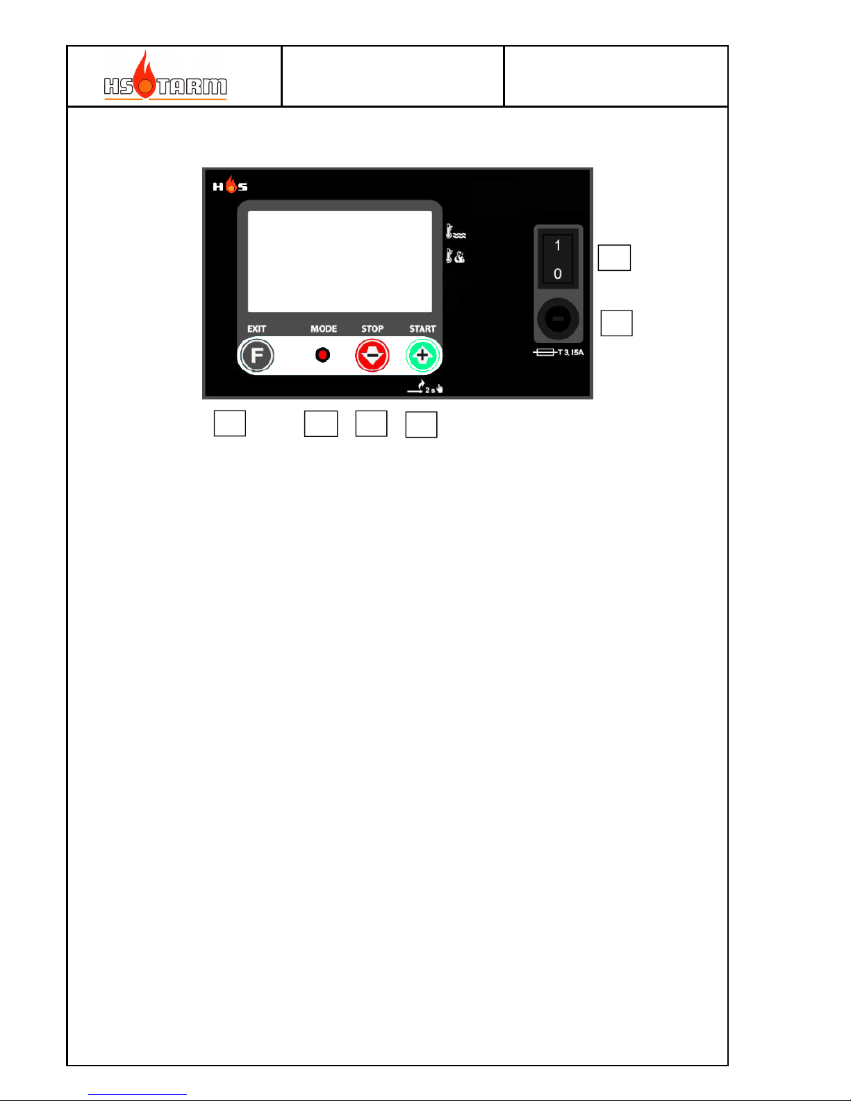
Control panel
(A) Function button; short press: shifts between boiler and flue gas temperature
indication; long press: access to parameters behind PIN code
(B) LED indicator
(C) STOP and minor setting button
(D) START and higher setting button
(E) Main fuse
(F) Mains ON/OFF
Detailed description of the boiler (see paragraph 1.1)
1. Control panel
2 Loading door These dimensions allow easy wood loading
3 Primary air setting Adjust the primary air necessary for the combustion.
4 Secondary air setting A
djust the secondary air necessary for the combustion
5 Ash door Behind this door, the combustion take place. This door is also
used to take away the ashes regularly.
6 Flame control sight glass This sight glass is used to set up the combustion.
7 Tunnel This is the heart of the combustion.
8 Secondary air exit The secondary air enters the combustion in the high
temperature zone
9 Primary air exit The primary air is diffused in through the wood logs
10 Removable heat plates They limit the shooting up of the boilers body and diffuse
the primary air
11 Tubular heat exchanger The tubular heat exchanger is used to recover the heat from
the flue gases. They are equipped with turbulators.
12 Flue gas box Collect the flue gas and ashes before evacuation.
13 Suction fan Brings the necessary air for the combustion.
14 Cleaning hatch The cleaning is regularly done by this hatch.
15 Cooling coil It serves to cool down the boiler in case of overheating.
16 Flow
17 Return
A
B
C
D
E
F
MANUAL
HK2 – HK4 25-08-2014
Page
5
1.1.1 Use of the heating boiler with storage tank (See page 3):
The HK boilers are wood log boilers, for chopped wood having the same length as loading
chamber. The good performance links to the association of a minimum storage tank volume.
It is not a continuous fire like a stove. An essential characteristic of the boilers is the
presence of a suction fan situated in the flue gas exit on the back of the boilers.
The primary and secondary air leads to the combustion zone by ducts to obtain an ideal air
speed and mixture for ideal combustion.
The primary combustion air runs through the primary air valve (3) into the side of the lower
part of the loading chamber. The position of this valve adjusts the rate of air necessary to
generate the power.
The secondary air streams at high speed to the hot zone of the combustion by valve (4). It
enters through the ceramic slot (visible by the loading door) and diffuses through the
diffuser holes situated in the combustion air-mixing slot.
The combustion continues from the hot air-mixing slot into the combustion tunnel in which
the combustion finalizes at very high temperature (1000°C to 1200°C), thus minimizing
pollution and production of ash and optimizing the efficiency.
The best efficiency / combustion obtained by having a good control of the primary and
secondary air, according to characteristics of combustion (calorific power of the type of
wood, hygrometry and age). This implies that the fan works continuously when there is
wood in the boiler, and so that the boiler can permanently evacuate the energy produced by
the combustion. To obtain the correct way of working requires installing of a hydroaccumulation volume with the correct dimensions (energy storage / storage tank).
The role of energy storages is to ensure good working of the boiler even when the energy
demand is weak (mild days of winter, autumn, spring, summer). It is a matter of absorbing
the surplus of energy produced by the boiler. This stored energy will be returned to the
heating system and in the domestic hot water according to demand. Thus, when the storage
tank(s) are full of energy (75°C or 80°C at the lowest point) the boiler must be empty of
wood, must not be reloaded, and the suction fan will stop working . The boiler will be
reloaded with wood when the storage tank(s) will be emptied of their energy (30°C to 40°C
at the highest point according to the type of installation, without active take over; 60°C at
the highest point with an active take over) with only the necessary quantity of wood to
reheat the storage tank(s). It is possible to reload the boiler with wood before the storage
tank(s) become completely emptied of their energy (for example at night before going to
bed), but loading only the quantity of wood necessary to reheat the storage tank(s).
So it is necessary to always consult the different thermometers of the storage tank(s) to
know the quantity of wood that you can load. This system supplies the energy with optimum
efficiency and a normal function, which ensures autonomy.
Thus this system allows the boiler running in the best conditions and avoids the slowing
down phases (the boiler in high temperature, boiler still loaded, very weak energetic
demand, suction fan stops). The slowing down provokes a bad function, an abnormal soot
build and premature use of the boiler by a corrosion due to the acids in the woods which
have not been burnt. Therefore, it is vital never to reload the boiler when the storage
tank(s) are full of energy. It is necessary to let the fire shut down if the storage tanks
discharging are long (weak energetic demand). HK boilers are not continual fire boilers.
MANUAL
HK2 – HK4 25-08-2014
Page
6
Guarantee and claims
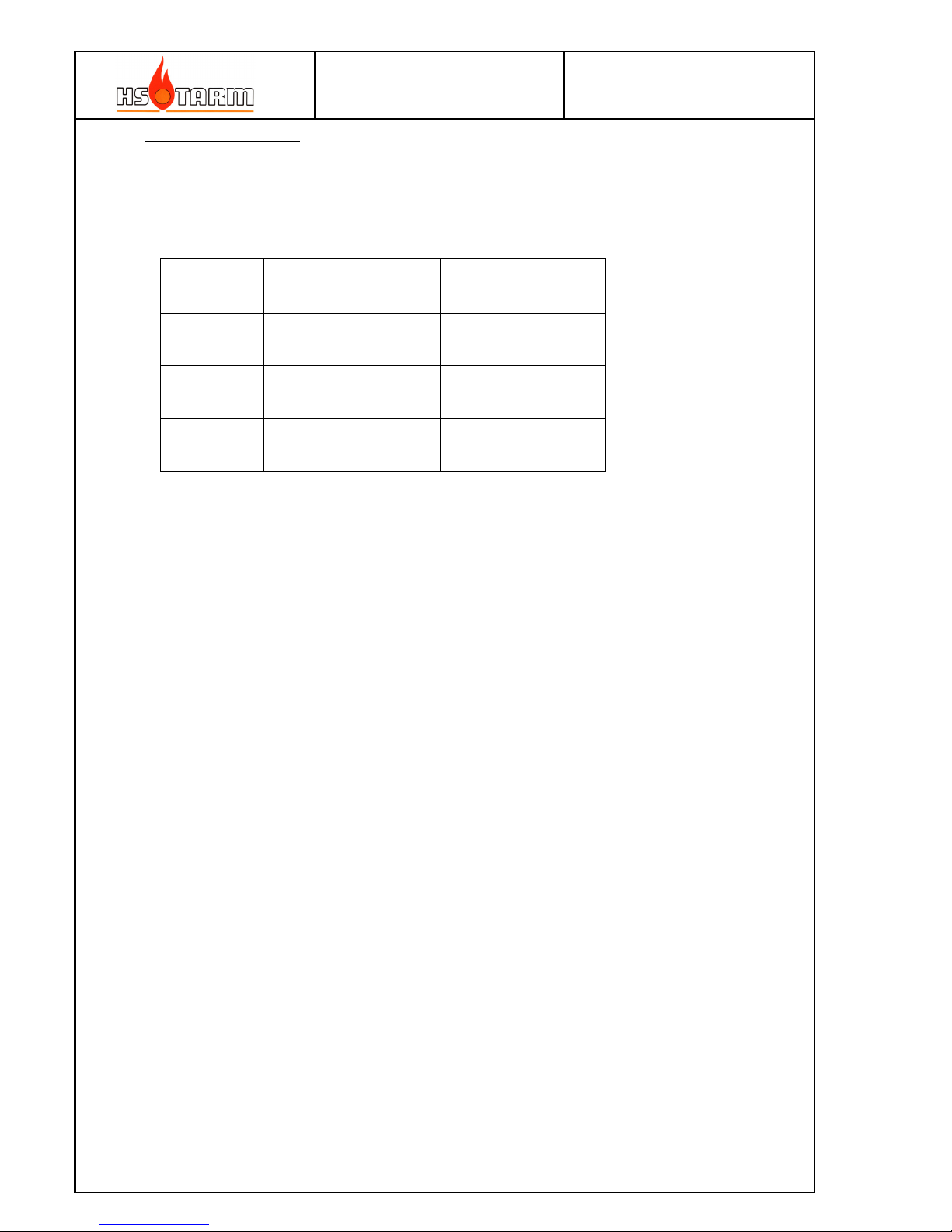
If the boiler is not connected to a storage tank of at least the size as stipulated in the below
table, the guarantee accorded by the constructor is not valid.
The useful storage tank volume:
Volume in
liters
Obligatory minimum
working volume
Advised working
volume
HK2 1250 1500
HK3 1750 2000
HK4 2250 2500
1.2 Responsibility, security and duty of user
1.2.1 Responsibility
The user is responsible for the use of the boiler. The user shall at all times respect the
instructions given in this manual. Failing to follow the instructions will jeopardize the
function of the boiler, its efficiency, its life-duration, increase waste pollutants, and cancels
the guarantee on the product.
It is understood that the user shows a real willingness and capacity to the use a wood log
combustion boiler, and appreciate that a biomass heating system constitutes a workload and
the necessary obligations reduces the advantages offered by the ecologic combustible fuel.
1.2.2 Rules of safety
In the case of defects or poor functions, it is necessary to call your heat installer. A sufficient
air supply (ventilation) in the heating room is necessary, and it shall never be obstructed.
Never store dangerous or inflammable material in the heating room. Do not let children near
the boiler. Do not let unqualified people use the boiler.
1.2.3 Duties of user
The user must maintain very regularly the boiler, the installation, and to fulfill in particular:
- General rules of safety
- The respect of these directions
- The respect of instructions relating to the accessories
- The current regulations. An annual maintenance by a qualified
professional is advisable.
1.2.4 Local installation requirements
Be aware of local building regulations, which can call for special initiatives for the installation
of this boiler and its accessories.
MANUAL
HK2 – HK4 25-08-2014
Page
7
1.3 General instructions of use
1.3.1 The wood, solid fuel
HK boilers are heating boilers, which use wood logs of forest wood. Almost all types of
woods will do.
The wood must be dry - moisture content lower than 25 %. This ensures good function of the
boiler and sufficient power.
NB: using wood with a moisture content lower than 15 % requires attention; do adjust the
primary air setting lower than normal to avoid ignited gas reentry to the wood log
compartment, which will result in intermediate gas combustion in this place, i.e. jumping
combustion.
If such situation occurs – be very careful if opening the wood log-filling door: explosive
backfire out the door can occur.
Old wood, woodworm, or having been a long time in a humid place is not suitable; it results
in power loss and incomplete combustion.
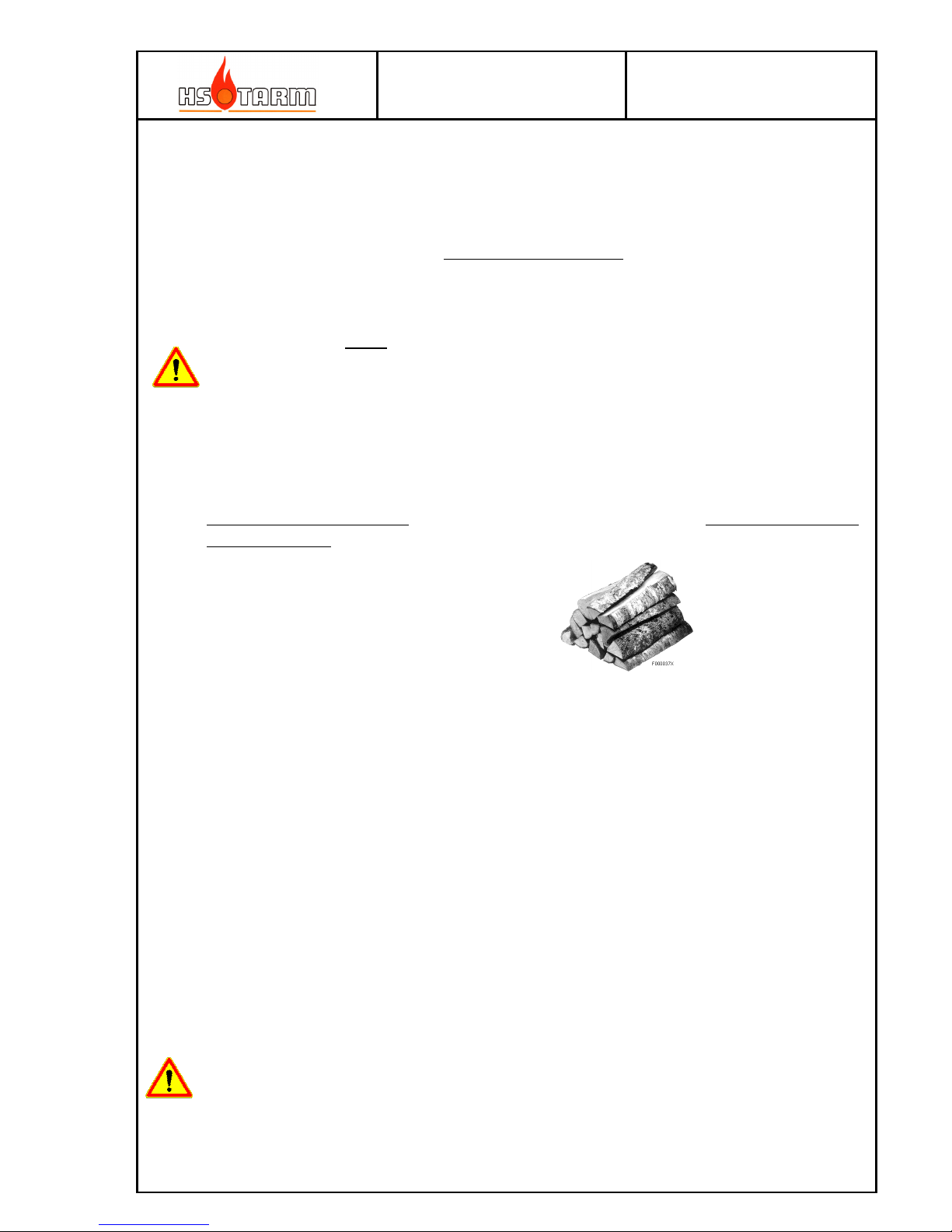
The wood must be chopped (10 to 15 cm of maximum diameter) and sawn in the length of
burning chamber to ensure a good function of the boiler without power loss.
Logs of 50 cm
Chopping and sawing the forest wood makes the quickest and most efficient drying
process. Stock it immediately under shelter (well aired, outside or inside). It must be
storage approximately two and half years to dry. Otherwise, a minimum of 3 years of
storage is necessary.
Wood exposed for a long time to bad weather or ageing (over 6 years) loses calorific
power: The consummation increases and the power from the boiler decreases. The
combustion is incomplete (soot and blackish-brown).
The boiler construction is not designed to work with treated wood from carpenters
workshops or industrial waste; a bad function will result as well as premature deterioration
of the boilers and their components.
1.3.2 Before the first use:
- Check the electronic and hydraulic connections.
- Purge the installation and check the pressure in the installation.
NEVER START THE BOILER WITHOUT WATER FILLING!

MANUAL
HK2 – HK4 25-08-2014
Page
8
1.3.3 First and regular use
Before beginning, assure the good fitting of the suction fan, of its electrical supply, of the good
fitting of the combustion tunnel and the good setting of the primary and secondary air inlets.
1. Switch on the boiler - (F) to "1". Make sure that the lower door is closed and secured (locking
screw). Load a little amount of paper, small pieces of kindle wood, in sufficient quantity and
again some papers on top, then light them up.
2. Turn on immediately the suction fan by pressing the (D) button.
Start from cold boiler (actual flue gas temperature < minimum flue gas temperature) will
boost the fan speed until the timeout has passed or the minimum flue gas temperature is
reached – see parameter list in paragraph 3.9.
The air needed for combustion is already here, the fire starts very fast. Let the loading door a
bit open to ensure enough air for the ignition of the kindle wood (1 to 3 minutes, stay ahead
to watch)
3. The combustion has well ignited and a small bed of embers has formed. Open the upper
door with care: only a few centimeters first for a couple of seconds. Then load 3 to 4 thin
logs, then the necessary quantity of wood and reclose the loading door.
4. At the first use or in case of a change in the type of wood: as the boiler water gets hot
(>65°C): fine tune / adjust the primary and secondary air according to the table of paragraph
1.3.4, then fine tune the secondary air with the help of three figures shown on paragraph
1.3.5 while looking through the sight glass of the ash-discharge door in front of the tunnel. If
the inspection glass is dirty, unscrew the lid and clean the glass with the aid of a scouring
sponge.
The air adjustments need no longer to be modified, except in case of changing the
characteristics of the fuel.
The other starting operations are carried out at each new heating.
NOTE :
If pressing the fan button for more than 2 seconds as the fan is already running and the boiler is not
any longer in the start phase the fan will speed up for 5 minutes. This function is used for refilling the
wood log chamber for continuous combustion. The extra fan speed is used to both make the flue gas
by-pass more efficient and to re-start the combustion.
A
B
C
D
E
F

MANUAL
HK2 – HK4 25-08-2014
Page
9
1.3.4 Primary and secondary air settings
In connection with the first start-up of the boiler, it is recommendable to make an emission test.
This procedure is in some countries regulated by law. To assure the correct procedure – ask the local
chimneysweeper for guidance.
1.3.5 Fine tuning of the secondary air
1.3.6 Minimum flue gas temperature setting, only for installer or advertised user.
The sensor is placed in sensor pocket in the fan housing (on the top of the body, at the back
left) and measures the flue gas temperature (factory setting to 90°C).
It is when this temperature goes down that the suction fan cuts itself off definitively when
there is no longer any wood in the boiler and the temperature of the flue gas decreases. This
to avoid unnecessary cooling down from airflow through the boiler.
1.3.7 Boiler temperature setting, only for installer or advertised user.
The normal temperature of the boiler is at least 85°C (factory setting 87°C). With the
« recyclable Kit D 60°C », an optional supply, the temperature of the boiler will stabilize at
about 62°C/65°C, as long as the boiler is in phase with storage tanks load. When the storage
tanks are loaded at least at 60°C at the lowest point, the boiler temperature will increase like
the storage tanks until the adjusted temperature.
Good setting. The flame
« just » leaves the
furnace, yellow and light
blue-tinged.
Too much secondary air.
The flame is too short and
blue-tinged: reduce the
secondary air.
Not enough secondary air.
The flame is too long and
orange / reddish: increase
the secondary air
Basic air settings
Primary air (high)
indication 3
Secondary air (low)
indication 4
Leafy trees/deciduous 30% 70%
Softwoods/evergreen 50% 40%
MANUAL
HK2 – HK4 25-08-2014
Page
10
The optimal adjustment will bring the boiler temperature just below the setting of the boiler
temperature set point as the fan stops; having the setting too low will bring the fan to stop
when the combustion is still active; this is an unwanted mode and will lead to soot and a
dirty boiler.
NOTICE: The temperature safety valve (the valve connected to the cooling coil) is starting to
open at about 95°C. Thus, it must be taken care not to set the boiler thermostat
to more than 87°C in order to avoid an untimely shutting down of the security.
1.3.8 Safety thermostat (STB) – situated on front left of controller
The thermostat switches off at 100°C and stops the electric supply of the suction fan. If this
happens, it is advisable to:
- Wait for the boiler to cool down to 75 °C.
- Unscrew the cap of the thermostat (situated on the front left to the controller), push the
little button, screw on the cap
- Use again the boiler as normal.
If this happens again, it is advisable to check the following points by your heating installer:
- Check the function of the safety thermostat.
- Check that the use of the boiler has been correct
- Check that the boilers hydraulic system is correct (recycling system in a good state...)
- Check the function of the temperature safety valve
- Check the function of the boiler temperature sensor.
- Check that the chimney draught is not too strong (draught stabilizer is in a good state and
well adjusted).
- Check if there is some power supply’s cuttings (main electrical supply)
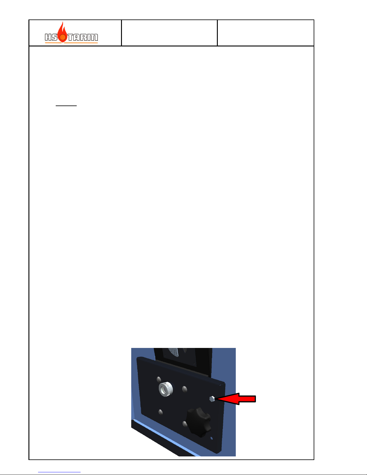
1.3.9 Ash door locking
The screw provided for this purpose shall be mounted as the boiler are in use (combustion is
going on). Remove the screw only if the boiler is cold (no combustion).
MANUAL
HK2 – HK4 25-08-2014
Page
11
1.3.10 Fuse
The fuse located on the front of the control panel is 3.15 A (∅ 5 mm × 20 mm).
It blows if overload appears – replace only with an equivalent. Contact an electrician if the
fuse blows frequently.
1.3.11 Quick break down search (considering that the hydraulic attachment is correct)
Case 1: The boiler works, but the temperature does not increase properly:
Or: The temperature increases but the storage tanks heat up with difficulty and the heating
is weak.
- Check the air settings (open the primary air valve as necessary).
- Check if the heat exchange pipes, the loading chamber and the combustion tunnel are
clean (see 1.3.12 Cleaning and maintenance).
- Check if the primary air exit in the chamber (in front of you, behind the hanging plates,
just above stones) is cleared. Too great a layer of ash may be found in the burning
chamber, a more regular cleaning is required. After a few working years, a complete
cleaning of air ducts may prove useful: take out the air valves situated between the two
doors and clean all the ducts.
- Check if the door seals, the hatches for ash removal are waterproof. A bad
waterproofness leads to an external unwanted air intake away from the combustion
which leads to a loss of power and a bad function.
- Check the condition of the suction fan blade coupled to the motor (see 1.3.12 Clean and
maintenance).
- Check the temperature of the flue gas: it must be in the range of 130°C to 150°C. If it is
too low, the wood is probably not suitable. Try with a different type of wood or different
stock.
- Have the moisture content in the wood controlled with the help of a hygrometer (by
your installer).
- Check the good hydraulic connection, in good equilibrium (heat pump(s))...
Case 2: The boiler temperature increases but does not emit energy:
- Check the good function of the recycling pump.
- In the case of a "recyclable Kit D 60°C", check the openings of stop flaps and the
condition of the thermostatic cartridge, the heat pump motor (these components are
available as separate parts).
Case 3: The boiler stops when the wood is not consumed and the storage tanks are not loaded:
- The minimum flue gas temperature is incorrectly set (the base adjustment is around
90°C), its sensor is not in its place, or it is defective (A4 alarm).
- The wood may be too long, too wet, or in a bad position in the burning chamber: the
wood stays trapped, and does not subside during the combustion and it goes down until
there is no significant power, and the temperature of the flue gas decreases below the
minimum setting.
-
The combustion stifles by a lack of ash sweeping in the burning chamber or in the tunnel
or behind the tunnel, the power is lacking, the temperature decreases below the
minimum setting (H).
- The wood is wet and the temperature of the flue gas is too weak (no power).
 Loading...