

HSMC HE8551 Datasheet
HI-SINCERITY
MICROELECTRONICS CORP.
Spec. No. : HE6113-B
Issued Date : 1992.09.30
Revised Date : 2000.09.20
Page No. : 1/3
HE8551
PNP EPITAXIAL PLANAR TRANSIST OR
Description
The HE8551 is designed for use in 2W output amplifier of portable radios
in class B push-pull operation.
Features
High Tot al Power Dissipat ion (PT: 2W, TC=25°C)
•
High Collector Current (IC: 1.5A)
•
Complementary to HE8051
•
Absolute Maximum Ratings
Maximum Temperatures
•
Storage Temperature....................................................................................................... -55 ~ +150 °C
Junction Temperature ............................................................................................... +150 °C Maximum
Maximum Power Dissipation
•
Total Power Dissipation (Ta=25°C)................................................................................................... 1 W
Total Power Dissipation (Tc=25°C)................................................................................................... 2 W
Maximum Voltages and Currents (Ta=25°C)
•
VCBO Collector to Base Voltage.................................................................................................... -40 V
VCEO Collector to Emitter Voltage ................................................................................................. -25 V
VEBO Emitter to Base Voltage......................................................................................................... -6 V
IC Collector Current...................................................................................................................... -1.5 A
IB Base Current ............................................................................................................................ -0.5 A
(Ta=25°C)
Characteristics
Symbol Min. Typ. Max. Unit Test Conditions
BVCBO -40 - - V IC=-100uA, IE=0
BVCEO -25 - - V IC=-2mA, IB=0
BVEBO -6 - - V IE=-100uA, IC=0
ICBO - - -100 nA VCB=-35V, IE=0
IEBO - - -100 nA VEB=-6V, IC=0
*VCE(sat) - - -0.5 V IC=-0.8A, IB=-80mA
*VBE(sat) - - -1.2 V IC=-0.8A, IB=-80mA
VBE(on) - - -1 V VCE=-1V, IC=-10mA
*hFE1 45 - - VCE=-1V, IC=-5mA
*hFE2 85 - 500 VCE=-1V, IC=-100mA
*hFE3 40 - - VCE=-1V, IC=-800mA
fT 100 - - MHz VCE=-10V, IC=-50mA, f=100MHz
*Pulse Test : Pulse Width ≤380us, Duty Cycle≤2%
Classification on hFE2
Rank B C D E
Range 85-160 120-200 190-300 250-500
HSMC Product Specification
HI-SINCERITY
MICROELECTRONICS CORP.
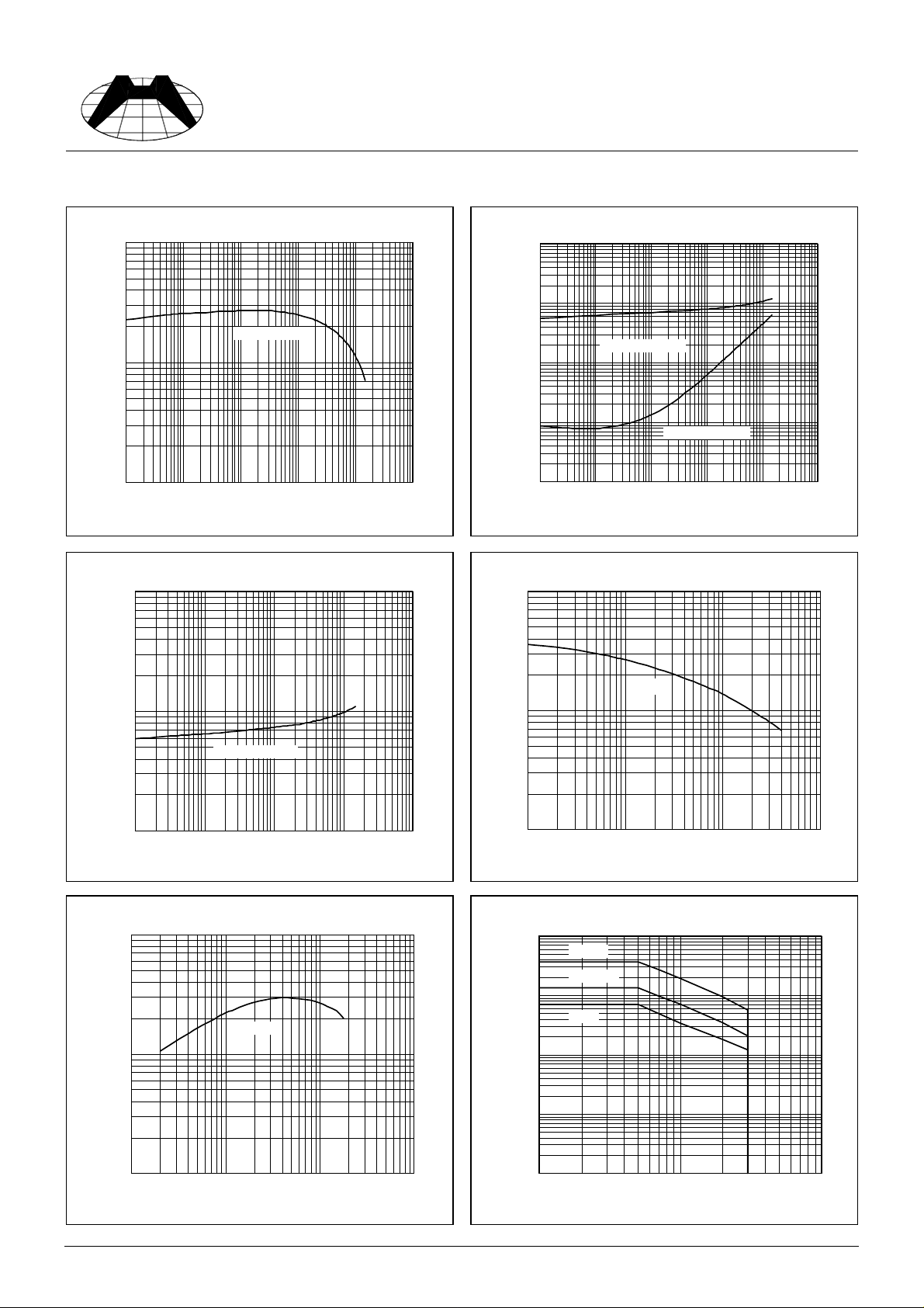
Characteristics Curve
Spec. No. : HE6113-B
Issued Date : 1992.09.30
Revised Date : 2000.09.20
Page No. : 2/3
1000
100
hFE
10
0.1 1 10 100 1000 10000
Current Gain & Collector Current
hFE @ VCE=1V
Collector Current (mA)
On Voltage & Collector Current
10000
10000
1000
BE(sat)
V
@ IC=10IB
100
Saturation Voltage (mV)
10
1
0.1 1 10 100 1000 10000
CE (sat)
V
@ IC=10I
Collector Current (mA)
B
Capacitance & Reverse-Biased Volt age
100
Saturation Volt age & Coll ector Current
1000
On Voltage (mV)
100
1 10 100 1000 10000
BE(on)
V
@ VCE=1V
Collector Current (mA)
Cut off Fr equency & Collector Cu rrent
1000
VCE=10V
100
Cutoff Frequency (MHz)
Cob
10
Capac itanc e (pF)
1
0.1 1 10 100
Reverse-Biased Vol t a ge ( V)
Sa fe Operating Area
10000
1000
(mA)
C
100
Collector Current -I
10
PT=1ms
PT=100ms
PT=1s
10
1 10 100 1000
Collector Current (mA)
1
1 10 100
Forwar d Voltage-VCE (V)
HSMC Product Specification
 Loading...