

HSMC H31002P Datasheet
HI-SINCERITY
MICROELECTRONICS CORP.
Spec. No. : Preliminary Data
Issued Date : 1998.08.01
Revised Date : 1999.06.01
Page No. : 1/4
H31002P
BIPOLAR TONE RINGER ICS
Description
The H31002P is a bipolar integrated circuit. It is designed for
telephone bell replacement.
Features
Current consumption is small.
•
Package is compact. (DIP-8 pin)
•
Oscillation frequency is variable.
•
Built-in threshold circuits prevent false triggering due to power noise as well as 'chirps' due to
•
rotary dial.
Few external components.
•
Applications
Telecom Tone Rin ger Set
•
Absolute Maximum Rating
(Ta = 25°C)
Characteristics Symbol Rating Unit
Supply Voltage VCC 30 V
Power Dissipation PD 500 mW
Operating Temperature Topr
Storage Temperature Tstg
-40°C to +85°C
-55°C to+150°C
°
°
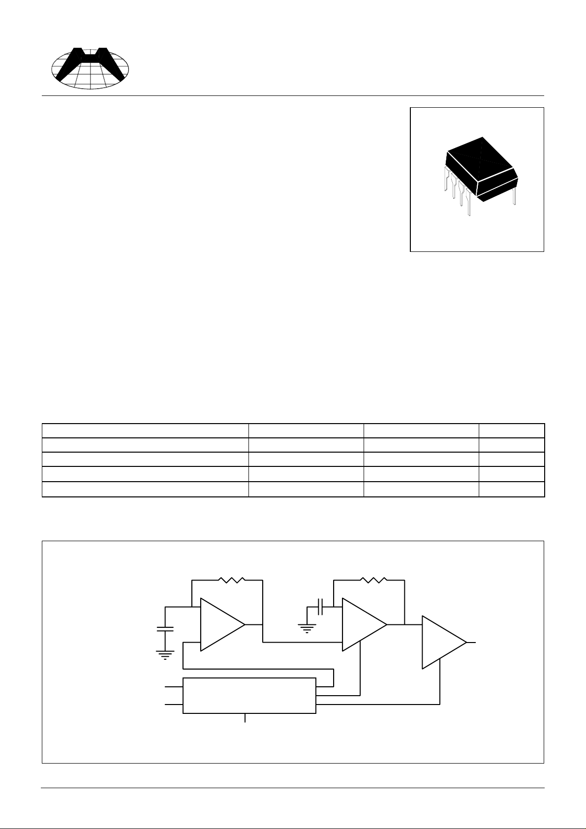
Block Diagram
R1 R2
C2
7
High
OSC
6
AMP
8
C1
3
Low
OSC
4
C
C
1
5
Power Supply
(With hysteresis)
2
HSMC Product Specification
Pin Connections
HI-SINCERITY
MICROELECTRONICS CORP.
Spec. No. : Preliminary Data
Issued Date : 1998.08.01
Revised Date : 1999.06.01
Page No. : 2/4
5678
Pin1 : Vcc Pin5 : Gnd
Pin2 : RSL Trigger In Pin6 : High Freq. Time Constant.
Pin3 : Low Freq. Time Constant. Pin7 : High Freq. Time Constant.
1234
Pin4 : Low Freq. Time Constant. Pin8 : Output
Electrical Characteristics
Characteristics Symbol Test Cond ition Min. Typ. Max. Unit
Operating Voltage V
Initiation Supply Voltage V
Sustaining Supply Voltage V
Initiation Current Consumption I
Sustaining Current Consumption I
Oscillator Frequency
"H" Level V
Output Voltage
"L" Level V
opr
sus
sus
f
f
H1
f
H2
OH
OL
(Note 1) 17 19 21 V
si
(Note 2) 10.5 12 - V
si
L
No Load 1.4 3.3 4.2 mA
C1=0.47uF, R1=165k
Ω
C1=6800pF, R2=191k
Vcc=24V, IOH =-10mA,
Pin 7=Gnd
Vcc=24V, IOL=10mA,
Pin 7=7V
Note 1 : Initiation Supply Voltage (Vsi) is a supply voltage required to start oscillation of the tone ringer.
Note 2 : Sustaining Supply Voltage (Vsus) is a supply voltage required to maintain oscillation of the tone ringer .
Note 3 : Oscillation frequency is determined by the following equations (1), (2) and (3) :
(1)fL=1/1.234, R1, C1 (Hz) (2) fH1=1/1.515, R2, C2 (Hz) (3) fH2=1.24 fH1 (Hz)
--29V
0.4 1.4 2.0 mA
91011
461 512 563
Ω
576 640 703
20 21.5 22.5 V
0.7 1.0 2.0 V
Hz
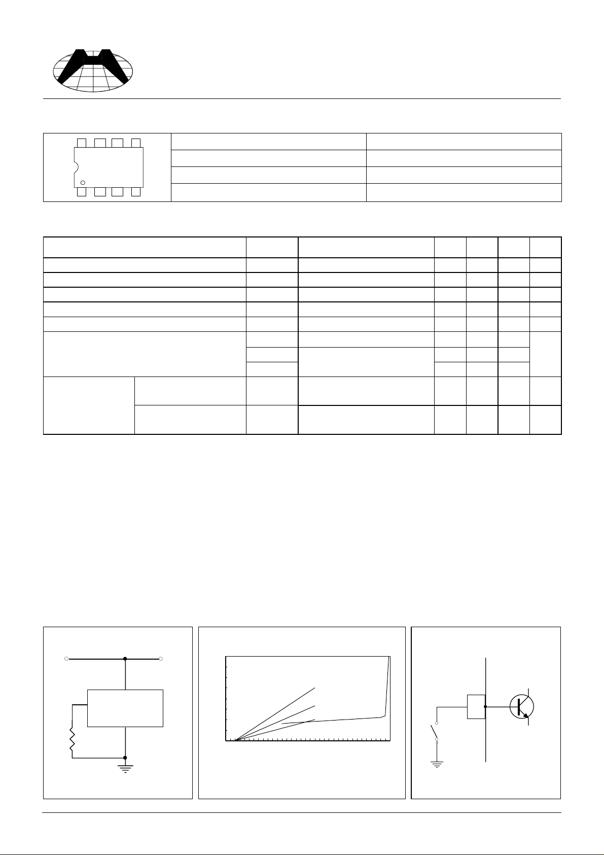
Method Of Using Rsl
In the H31002P, using the RSL terminal can change the initiation supply current (Isi). The
resistor RSL is connected to Gnd from Pin 2 as shown in Fig.3.
Further, the initiation supply current (Isi) can be changing the value of RSL. Fig.4 shows the
graph of Vs-Is characteristic at the time when RSL has been changed to three values. The Vs-Is
characteristic at the time when RSL=6.8 kΩ coincides with that at the time when Pin 2 of the
H31002P has been used at an open state. If Pin 7 is connected to Gnd as shown in Fig. 5, the
H31002P can stop oscillation. (the “L” level voltage is under 2V)
Fig.3
Vs
1
2
H31002P
5RSL
Gnd
Fig.4 Fig.5
8
7
6
5
4
3
2
1
0
0102030
C u r r e n t C o n s u p m p t i o n ( m A )
1 . R S L = 1 . 3 K 2 . R S L = 3 . 3 K 3 . R S L = 6 . 8 K
|
|
|
|
|
|
V s u s
1
|
|
2
|
3
|
|
V s i
|
S u p p l y V o l t a g e ( v )
HF1
Pin 7
Internal IC
HSMC Product Specification
 Loading...