

Page 1
2.991.999.120_en
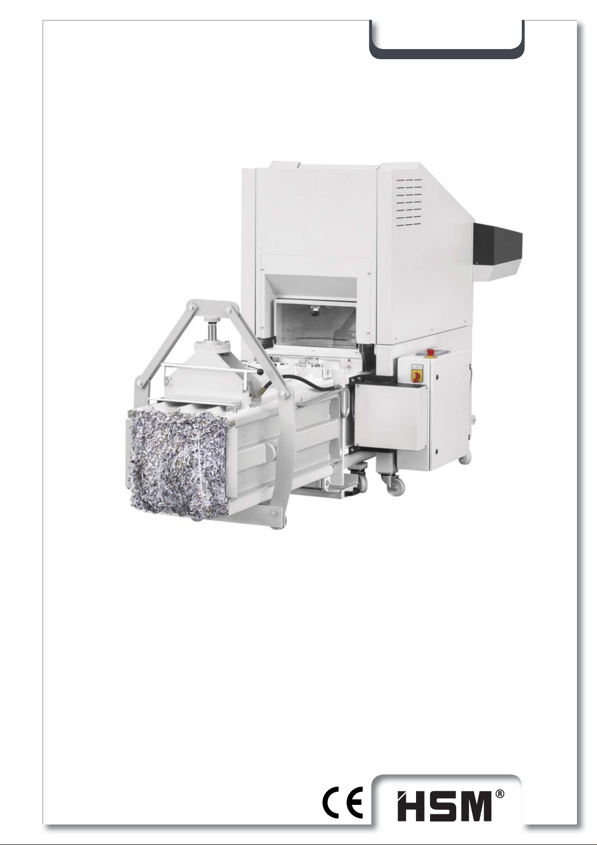
SP 5088
Keep this instruction for future use!
OPERATING MANUAL
CHANNEL BALING PRESS
SP 5088
Page 2

SP 5088
HSM GmbH + Co.KG,
Austraße 1-9,
88699 Frickingen / Germany
Tel. + 49 75 54 2100-0
Fax + 49 75 54 2100-160
[email protected]
www.hsm.eu
2 2.991.999.120_en 07/2013
Page 3

SP 5088
Contents
Nameplate 6
Foreword 7
1 Safety 8
1.1 Notes on safety....................................................................................................8
1.1.1 "Work safety" symbol ..........................................................................................................8
1.1.2 "Notice" symbol ...................................................................................................................8
1.2 Classifi cation of hazards......................................................................................8
1.2.1 Danger ................................................................................................................................8
1.2.2 Warning ...............................................................................................................................8
1.2.3 Caution................................................................................................................................8
1.3 Notes on work safety ...........................................................................................9
1.4 Proper use ......................................................................................................... 11
1.5 Inspecting the safety devices ............................................................................12
2 Technical data 16
2.1 KP 88.1 Combined press ..................................................................................16
2.1.1 Press data .....................................................................................................................16
2.1.2 Motor data .....................................................................................................................16
2.1.3 Hydraulics .....................................................................................................................16
2.1.4 Pump .............................................................................................................................16
2.1.5 Cylinder .........................................................................................................................16
2.1.6 Oil tank ..........................................................................................................................16
2.1.7 Noise emission ..............................................................................................................16
2.2 Shredder FA 500.3.............................................................................................17
2.3 Power requirement and fuse rate (3 x 400 V / 50 Hz) .......................................17
2.4 Operating conditions .........................................................................................17
2.5 Accessories .......................................................................................................17
2.6 SP 5088 explanatory diagram ...........................................................................18
2.7 Machine dimensions ..........................................................................................19
3 Preparations 20
3.1 General instructions...........................................................................................20
3.2 Siting the machine .............................................................................................20
3.3 Supply connections ...........................................................................................20
3.4 Settings..............................................................................................................20
3.5 Transporting the baling press ............................................................................21
3.5.1 Transport to another application site .................................................................................21
3.6 Transporting the shredder .................................................................................22
3.7 Assembling the shredder ...................................................................................23
3.8 Assembling the shredder press combination.....................................................24
07/2013 2.991.999.120_en 3
Page 4

SP 5088
4 Commissioning 27
4.1 Baling press controls .........................................................................................27
4.1.1 Accessing the SERVICE menu .........................................................................................30
4.1.1.1 Select setup mode (Bale fi nished / press channel / press ram) ............................................ 31
4.1.1.2 To display / clear the daily bale meter ...................................................................................32
4.1.1.3 Displaying / adjusting: Bale length or No. of strokes ............................................................. 32
4.1.1.4 Displaying / adjusting the actual values ................................................................................33
4.1.1.5 Adjusting the user language ..................................................................................................33
4.1.1.6 To display the error memory .................................................................................................. 34
4.1.1.7 System ..................................................................................................................................34
4.2 Shredder control panel ......................................................................................35
4.2.1 Display: Baling press not in automatic mode ....................................................................35
4.2.2 Display: Status of the baling press....................................................................................35
4.3 Initial start-up .....................................................................................................36
4.4 Running in the baling press ...............................................................................37
4.4.1 Setting the press channel adjustment cylinder .................................................................39
4.4.2 Relieve the press channel.................................................................................................40
4.5 Drawing in the strapping tape ............................................................................41
4.6 Automatic compression with light barrier ...........................................................42
4.7 Strapping procedure ..........................................................................................42
4.8 "Sacking" procedure ..........................................................................................44
4.9 Malfunctions of the baling press ........................................................................45
4.9.1 Error numbers ...................................................................................................................45
4.10 Malfunctions of the shredder .............................................................................46
4.10.1 Overload due to paper jam ..............................................................................................46
4.10.2 Electric motor overheats ...................................................................................................46
4.10.3 Emergency stop activated.................................................................................................46
4.10.4 Oil reservoir empty ............................................................................................................47
4.11 Stopping the machine ........................................................................................47
4.12 Outdoor use .......................................................................................................47
5 Inspection and maintenance work 48
5.1 Notes on maintenance.......................................................................................48
5.2 Maintenance of the baling press........................................................................49
5.2.1 Changing the hydraulic fl uid / venting fi lter .......................................................................49
5.2.2 Oiling and greasing moving parts .....................................................................................50
5.2.3 Empty the dust tray ...........................................................................................................51
5.3 Maintenance of the FA 500.3 shredder .............................................................52
5.3.1 Lubricating the drive chains and synchronized wheels (2 x per year) ..............................52
5.3.2 Retighten the feed belt ......................................................................................................53
5.3.3 Check the directional stability of the feed belt ..................................................................53
5.3.4 Check the feed belt for wear .............................................................................................53
5.3.5 Emptying the collecting tray ..............................................................................................54
4 2.991.999.120_en 07/2013
Page 5

SP 5088
6 Storage 55
7 Disposal instructions 55
7.1 Disposal verifi cation form ..................................................................................56
8 Using and ordering spare parts 57
8.1 Customer service address .................................................................................57
9 Electrical circuit diagrams 58
10 KP 88.1 hydraulic diagram 59
11 EC declaration of conformity 60
07/2013 2.991.999.120_en 5
Page 6
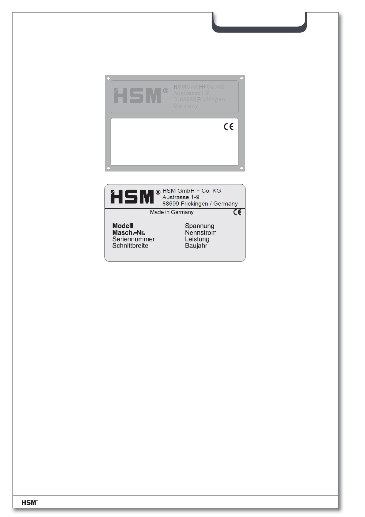
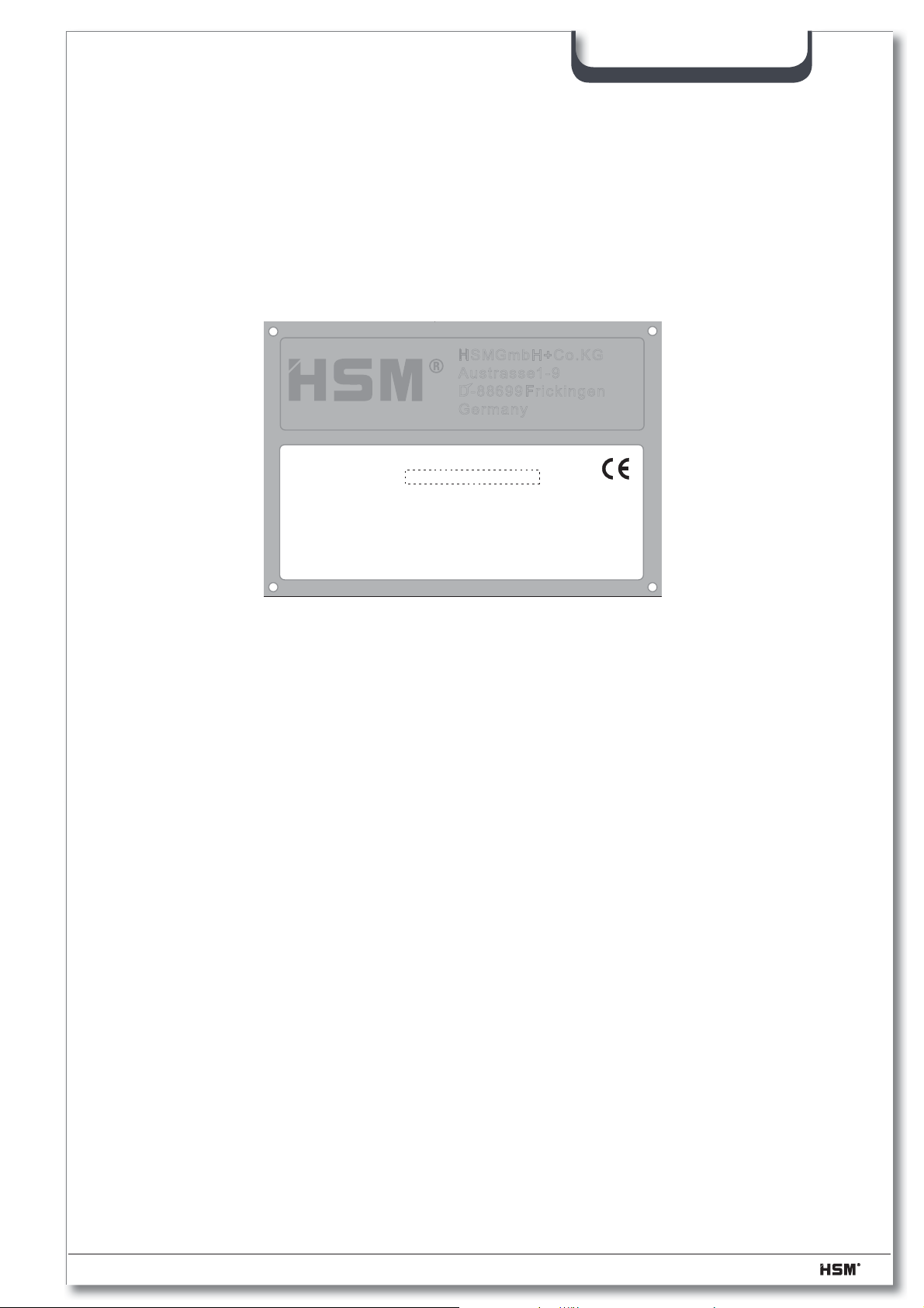
Nameplate
MODELL
MASCH.-NR.:
SERIEN - NR.:
PRESSKRAFT: kN
BAUJAHR:
HSM GmbH+Co.KG
Austrasse 1-9
D-88 699 Frickingen
Germany
LEISTUNG: kW
zH V :GNUNNAPS
NENNSTROM: A
SP 5088
The machine number is specifi ed on the nameplate of the baling press, shown
above. Guarantee claims and inquiries cannot be processed if you do not quote the
machine number.
Please therefore enter this number into the grey fi eld of the nameplate immediately
after receipt of the baling press.
6 2.991.999.120_en 07/2013
Page 7

Foreword
This Operating Manual informs you in detail about the start-up and maintenance of your
new baling press. It also contains notes on safety which must be observed.
To a great extent, the performance of your baling press depends on its proper application and thorough maintenance. You should carefully read this Operating Manual and
the notes on safety and always keep them safe at hand. You can thus prevent accidents,
maintain your guarantee claims against the manufacturer and always have an operative
baling press.
HSM GmbH + Co. KG permanently aspire to improve their products. They reserve the
right to perform any changes and modifi cations which are deemed necessary. However,
this does not imply the obligation for a subsequent modifi cation of already delivered ma-
chines.
Technical modifi cations as compared to the representations and statements in this Oper-
ating Manual which become necessary to improve the baling press are reserved.
SP 5088
This Operating Manual is intended for staff installing, operating and servicing the baling
press. It includes technical specifi cations and drawings which must not be copied, distrib-
uted or used for competitive purposes or given to third parties completely or in part.
Please contact your local dealer if you still have questions after having read this Operating Manual.
07/2013 2.991.999.120_en 7
Page 8
1 Safety
1.1 Notes on safety
1.1.1 "Work safety" symbol
This symbol marks all work safety notes in this Operating Manual which
endanger the health or life of people. Please pay attention to this symbol and
exercise particular care in such cases. Please also forward all work safety
notes to other users.
Apart from the instructions in this manual, you must also follow generally applicable safety and accident prevention regulations.
1.1.2 "Notice" symbol
This symbol marks information in this manual which requires particular attention so that guidelines, regulations, instructions and correct working
procedures are followed and damage to or ruin of the machine and/or other
equipment prevented.
SP 5088
1.2 Classifi cation of hazards
1.2.1 Danger
identifi es an immediate danger. If not avoided, it will result in death or severe
injuries (crippling).
1.2.2 Warning
identifi es a possibly dangerous situation. If not avoided, it could result in
death or severe injuries.
1.2.3 Caution
identifi es a possibly dangerous situation. If not avoided, it could result in light
or minor injuries. Is also used for warnings concerning damage to material.
8 2.991.999.120_en 07/2013
Page 9
1.3 Notes on work safety
Please pay particular attention to the following notes on work safety:
– The SP 5088 shredder press combination has been safety-tested by an accredited test-
ing station.
Nevertheless, incorrect operation and misuse can result in:
• the health or life of the operator
• the machine and other valuable equipment
• the effi cient operation of the shredder
– The SP 5088 shredder press combination has been built with the most up-to-date tech-
nology. However, the machine can be dangerous if improperly used, even by trainedstaff,
or if used for purposes other than those for which it was designed.
– The operation of the shredder press combination is always subject to local safety and ac-
cident prevention regulations.
– The employer must observe and comply with the “minimum safety and health require-
mentsfor the use of work equipment by workers at work”. Machinery Directive 2009/104/
EC
SP 5088
– The shredder press combination may not be operated by anyone under 16 years of age.
– All those charged with installation, assembly, disassembly, start-up, operation, inspection,
maintenance or repair of the baling press must have fi rst read and fully understood the
entire operating manual, paying particular attention to the “Safety” section.
– The shredder press combination may only be operated, serviced and repaired by author-
ised, trained staff. These staff must have been given special instructions on any dangers
which may possibly arise.
– Areas of personal responsibility for installation, assembly, re-assembly, set-up, operation
and maintenance must be clearly defi ned and strictly adhered to, in order to avoid confu-
sion which might compromise safety.
– When carrying out installation, disassembly, re-assembly, maintenance, operation, adjust-
ment and maintenance work always observe the shut-down procedures described in the
operating manual. Never perform this kind of work on the machine unless it is fully shut
down.
– Before performing such tasks make sure the drives and additional mechanisms of the
baling press cannot be switched on unintentionally. Turn the main switch to the “0” position and secure it. Pull out the power plug.
– Before starting the machine after repairs, make sure all protective devices are in place.
07/2013 2.991.999.120_en 9
Page 10

SP 5088
– Do not carry out any tasks which may endanger your safety while operating the machine.
– Any changes which take place and could impair safety should be reported immediately.
Put the machine out of operation until the damage is rectifi ed.
– Always make sure the machine is in perfect condition before you switch it on.
– Make sure the area around the machine is clean and safe.
– Unauthorised modifi cations and changes to the machine are strictly prohibited. Protec-
tive devices may not be removed or otherwise rendered inoperative.
– No work on the machine which is not part of its normal operation may be performed while
the machine is still running.
– Never open doors and fl aps before the machine has been shut down. Note the instruc-
tion plate.
– Test the protective measures installed after any electrical or repair work.
– No platforms or other raised surfaces may be placed near the shredder press combina-
tion if they encroach on the specifi ed safety clearances.
– Connecting cables must be laid in such a way that they cannot be tripped over.
– Only persons with the appropriate skills and experience in hydraulics may carry out work
on the hydraulic equipment.
– All lines, pipes and bolted joints must be regularly inspected for looseness, leaks and vis-
ible damage. Any damage must be repaired immediately. Escaping oil can cause fi re and
injury
– Any parts of the system and hydraulic pressure lines that need to be opened must be de-
pressurised according to the assembly instructions before commencing repair work.
10 2.991.999.120_en 07/2013
Page 11

1.4 Proper use
The SP 5088 shredder press combination is intended solely for shredding and pressing
paper and cardboard. The robust cutting unit is unaffected by staples and paper clips and
is even suitable for the destruction of whole volumes of fi les and folders. Excluding other
types of materials.
Operating mode :
Above-mentioned material is fed to the shredder. The crushed material falls through the
outlet of the shredder chute directly into the shaft of the press. The pressing operation is
initiated by a light barrier in the shaft when a certain level is achieved. The pressing plate
moves forward and presses the pressed material in the conical interference channel,
wherein it is compressed. The Shredder continues to run during the pressing process.
Once the bale has reached a certain length, it must be strapped manually. Then can
again be further pressed.
Due to the continuous pressing process, the sprue end compact bales ejected onto a
pallet or in a Plastic sack.
Any other use is considered improper. The manufacturer accepts no liability for damage
resulting from improper use - the operator carries sole responsibility for such use.
SP 5088
Proper use also includes carrying out installation, assembly, disassembly, start-up, operation
and maintenance work as prescribed by the manufacturer. The baling press may
only be operated, serviced and repaired by staff who are familiar with these regulations
and aware of the dangers.
The shredder press combination may only be operated by authorised, trained staff. Do
not carry out any tasks which may endanger your safety while operating the machine.
The relevant accident prevention regulations and any other generally recognised health
and safety standards must also be observed.
07/2013 2.991.999.120_en 11
Page 12

1.5 Inspecting the safety devices
Check the safety devices:
• at the start of every work shift (when operation was interrupted)
• at least once a week when the operation is interrupted
• after each maintenance or repair
Check the safety devices for:
• specifi ed condition
• specifi ed position
• safe attachment
• specifi ed function
Use the following checklist for your inspection. Correct any defects before starting
the machine!
If any defects arise during operation stop the machine immediately and ensure that the
defect is corrected.
SP 5088
Do not modify or remove any of the protective devices. Do not deactivate any of the protective
devices by modifying the machine.
Modifi cations to the machine are prohibited for safety reasons!
12 2.991.999.120_en 07/2013
Page 13
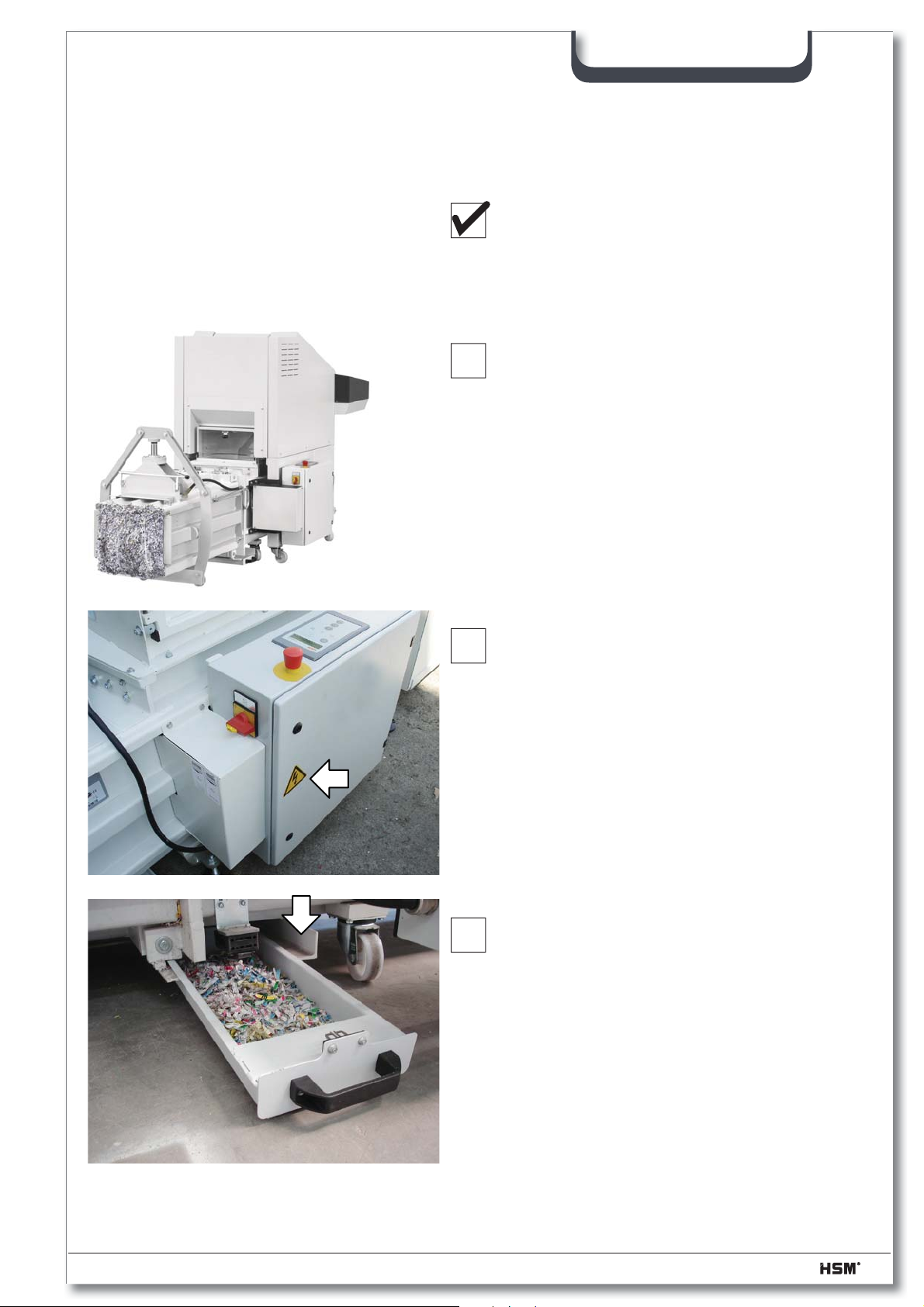
Checklist for inspecting the safety devices
Use the following list for your inspection of the safety devices.
Photocopy it for regular inspections.
Tick off the boxes if the check was successful.
Do not start the machine until you have checked every point.
1. All protective plates must be mounted and
fi rmly bolted on. (see picture)
SP 5088
2. The control cabinet must be closed and the
“Lightning symbol” warning sign affi xed to it.
3. Check the safety switch on the dirt drawer of
the baler. The safety switch turns the shredder
baler combination immediately or they may no
longer be turned on when the dirt tray is open
open
.
Try this function out!
07/2013 2.991.999.120_en 13
Page 14
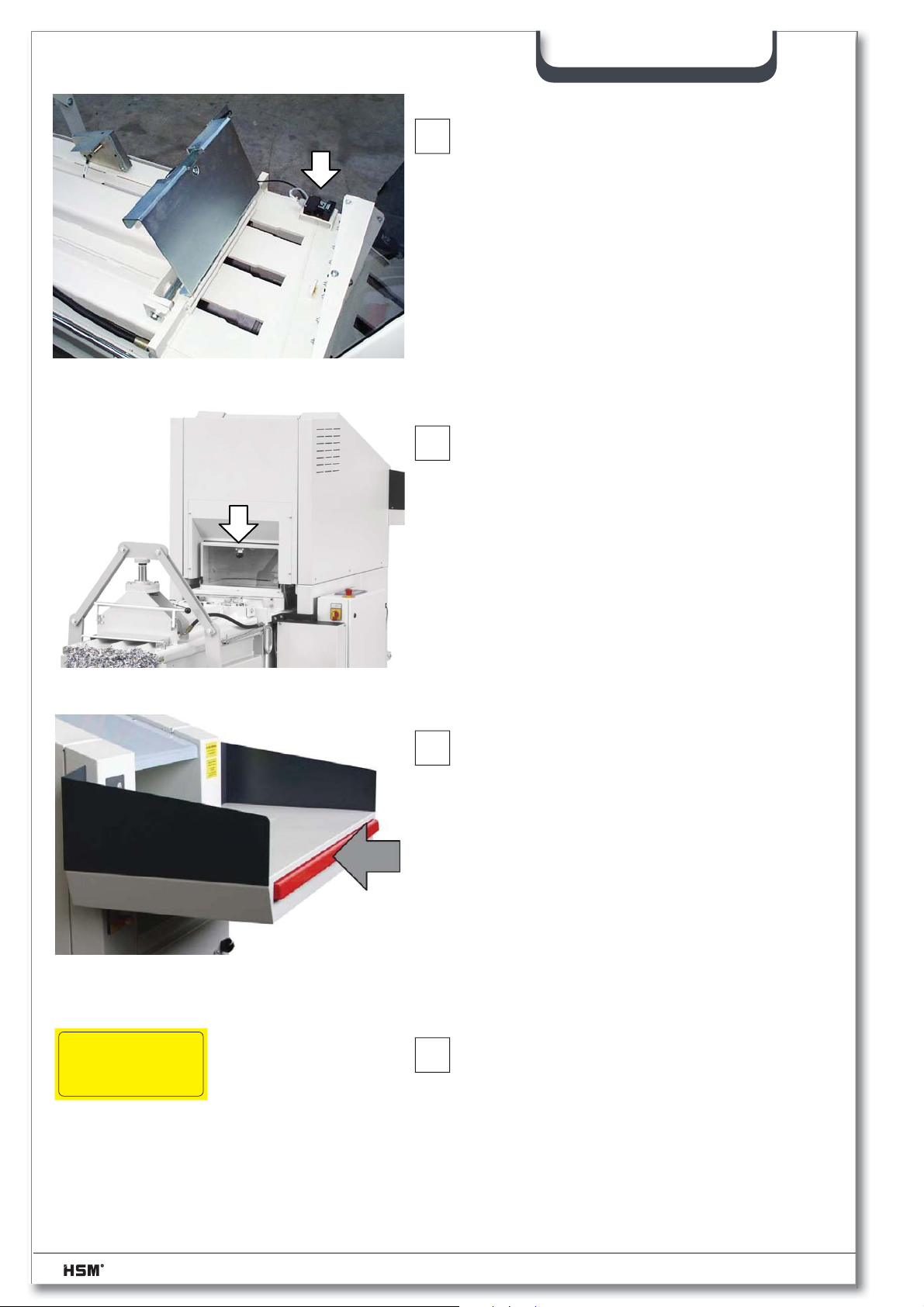
SP 5088
Ein-Mann-Bedienung
One-man operation
Un seul opérateur
4. Check the safety switch at the strapping fl ap.
When the strapping fl ap is open, the safety
switch immediately switches the machine off or
the machine cannot be switched on.
Try this function out!
5. Check the safety switch on the hopper. The
safety switch switches the shredder press combination off immediately and prevents it from being
switched on again when the inspection fl ap is
opened.
Try this function out!
6. When you press the emergency stop switch bar
whilst the machine is running, the shredder and
baling press must switch off immediately. The
machines can only be switched on again once
you have pulled out the switch bar.
Try this function out!
7. The safety sticker “One-man operation” must be
fi xed to the shredder.
14 2.991.999.120_en 07/2013
Page 15
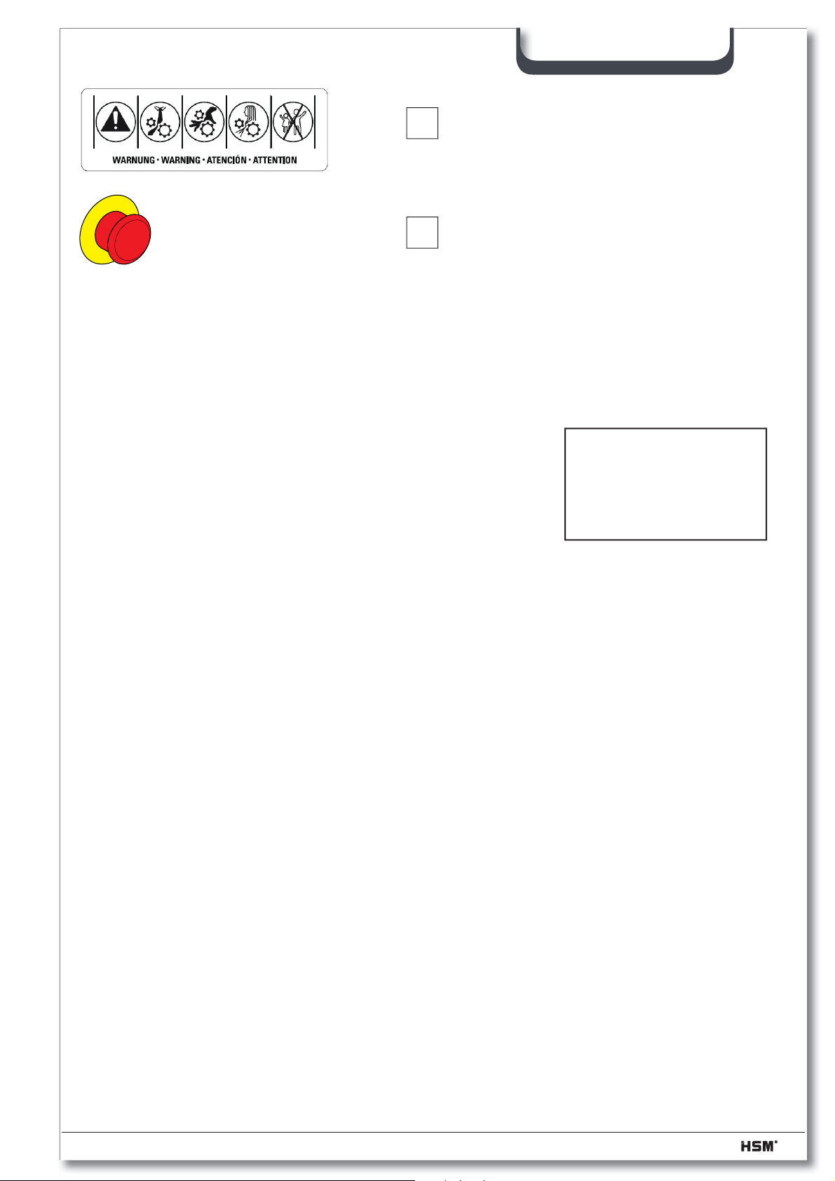
SP 5088
8. The “Safety instruction symbol” sticker must
be fi xed to the shredder.
8. If you press the emergency stop button when
the machine, shredder and baler must be
switched off immediately.
The machines can be turned on again until
you have unlocked the emergency stop button.
Try this function out!
checked
Date ..................
Signature ...............
07/2013 2.991.999.120_en 15
Page 16

2 Technical data
2.1 KP 88.1 Combined press
Weight ~ 880 kg
Size (L x W x H) see machine dimension
2.1.1 Press data
Pressing force 85 kN
Specifi c pressing force 30 N/cm²
Cycle time when idling (theoretical) 13 s
Bale size (L x W x H) 500 x 500 x 400-950 mm
Bale weight (depending on material) 40 – 70 kg
2.1.2 Motor data
Rated power P
Operating voltage U 400 V / 50 Hz
Rated current I
Output speed n
Protection class IP54
n
at U = 400 V 8,5 A
n
ab
4,0 kW
1450 min
SP 5088
-1
2.1.3 Hydraulics
Operating pressure 210 bar
2.1.4 Pump
Discharge Q 19,5 l/min
2.1.5 Cylinder
Pressing cylinder ø70/50 x 630 mm
Channel adjustment cylinder ø60/40 x 120 mm
2.1.6 Oil tank
Capacity 27 l
Oil grade multi-grade oil (DIN 51524-T3)
2.1.7 Noise emission
The sound pressure level, in accordance with DIN 45635 part 27, has the following values:
ISO viscosity grade HVLP 22
Idle 1 m / 7 m *) 71 / 69 dB (A)
Full load 1 m / 7 m *) 82 / 79 dB (A)
*) Distance measured between measuring instrument and machine surface at the hopper.
16 2.991.999.120_en 07/2013
Page 17
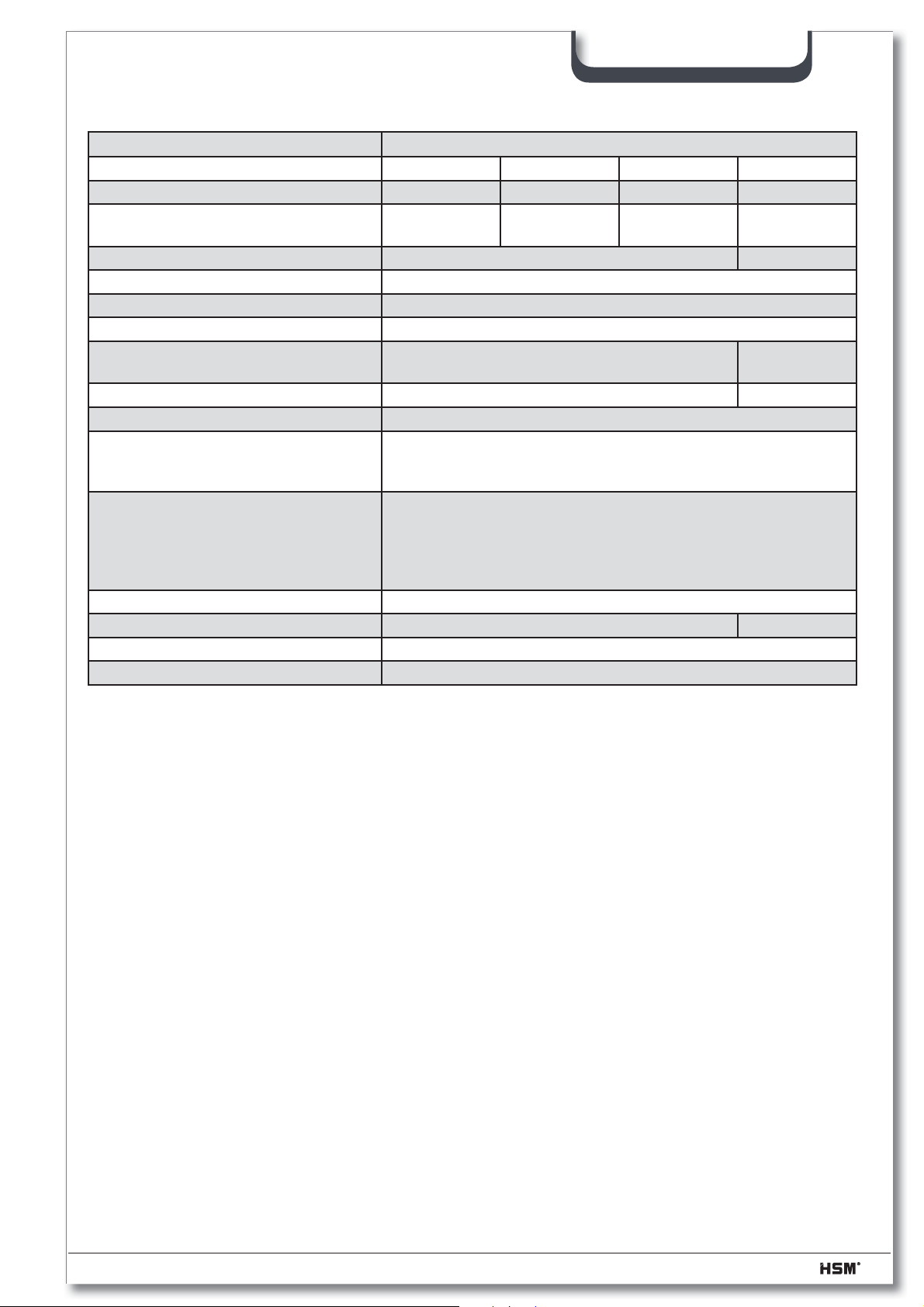
SP 5088
2.2 Shredder FA 500.3
Cutting type Particle cut
Cutting size (mm) 10,5 x 40 - 76 7,5 x 40 - 80 6 x 40 - 53 1,9 x 15
Security level DIN 32757 – 1 2 2 3 4
A4 (sheet) cutting performance 70 g/m
80 g/m
Throughput security level 4 200 - 250 kg/h
Intake width 500 mm
Cutting speed 210 mm/s
Power supply 3 x 400 V, 50 Hz
Power consumption with max. number of
sheets
Rated current 27 A 31 A
Plug industrial plug
Safety fuse
Line safety switch
Max. mains impedance
Ambient conditions for transport,
storage and operation:
Temperature
Relative humidity
Altitude above sea level
Dimenstions W x D x H (mm) 1170 x 1795 x 1795
Weight 790 kg 920 kg
Sound pressure level < 70 dB(A)
Shredded material container volume 530 l (2 x 265 l)
2
2
600 - 650
510 - 550
500 - 550
425 - 470
7,5 kW 5,5 + 4 kW
Typ „gl“ 35 Ampere
K oder C / 32 Ampere
0,1517 Ohm
-10 °C bis +40 °C
max. 90 %, without condensation
max. 2.000 m
400 - 450
340 - 380
120 - 130
90 - 100
2.3 Power requirement and fuse rate (3 x 400 V / 50 Hz)
KP 88.1 FA 500.3
Rated power P
Rated current I
n
n
4,0 kW 9,2 kW
8,5 A 18,1 A
Power connection plug CEE 32 industrial plug
Total fuse rating Shredder press combination 32 A
2.4 Operating conditions
Operating temperature - 10°C ÷ + 40°C
Operating humidity max. 90%, without-condensing
Operating altitude max. 2000 m above sea level
2.5 Accessories
PE gusseted bag 570/545 x 1150 x 0,1mm
Order no.: 1.452.995.000
07/2013 2.991.999.120_en 17
Page 18
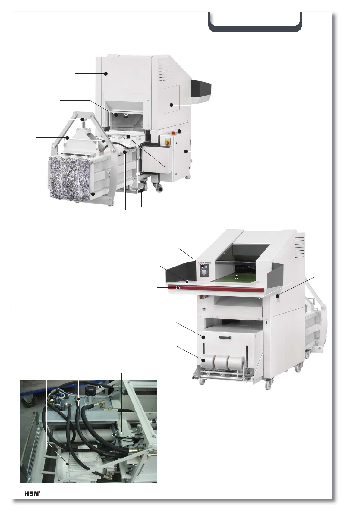
2.6 SP 5088 explanatory diagram
16
3
4
5
21
22
2
1
9
SP 5088
1 Press control cabinet
2 Press control panel
3 Inspection fl ap
4 Press channel adjustment
5 Polythene bag attachment
6 Press channel
7 Tape insertion needle
8 Dirt tray
9 Strapping fl ap
10 Hydraulic cover
11 Tape station
12 Press cylinder
13 Venting fi lter
14 Hydraulic tank
15 Press motor
1415 13 12
20
8
6
7
18
17
23
19
10
11
16 Shredder FA 500.3
17 Loading table
18 Shredder control panel
19 Emergency stop switch bar
20 Feed belt
21 Swivel roller with brake
22 Shredder inspection fl ap
23 Oil reservoir opening
18 2.991.999.120_en 07/2013
Page 19
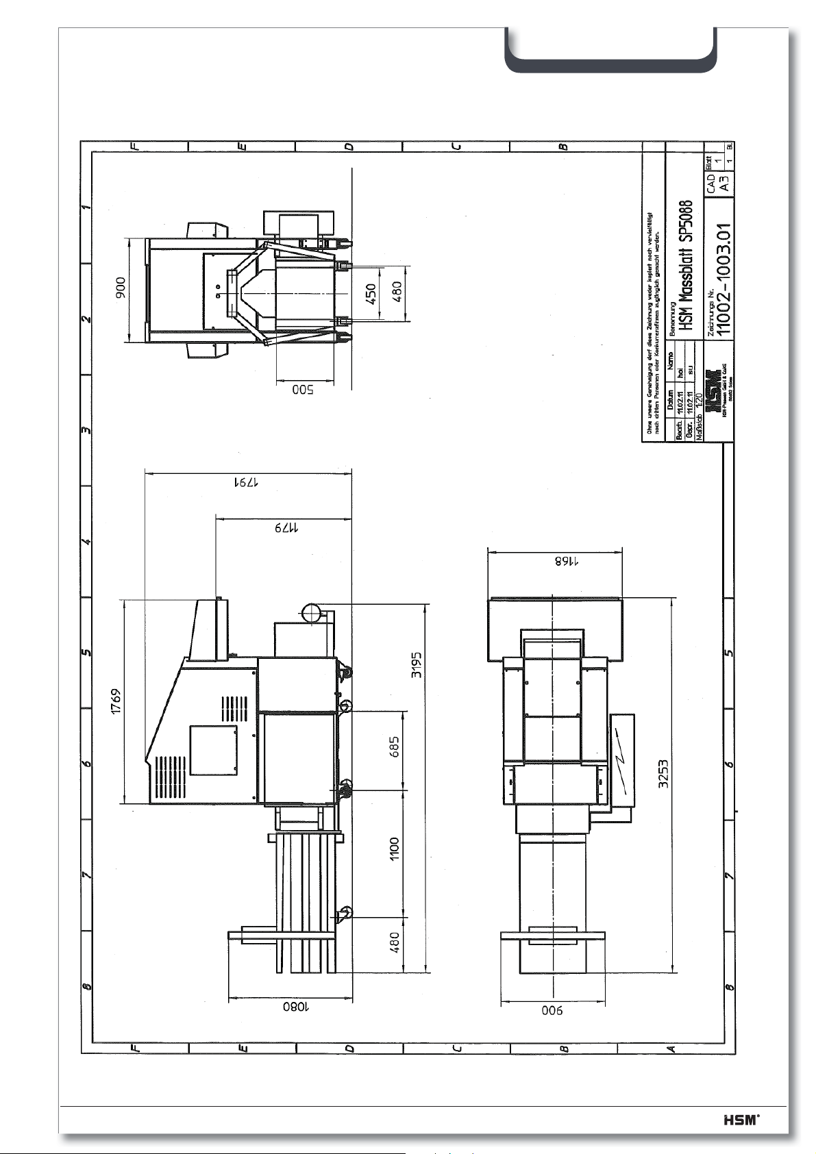
2.7 Machine dimensions
SP 5088
07/2013 2.991.999.120_en 19
Page 20
3 Preparations
3.1 General instructions
We strongly recommend that installation work on the baling press should be carried out
by trained HSM engineers.
We accept no liability for damage resulting from incorrect installation.
If you do perform installation tasks yourself, make sure you have read and fully under-
stood the entire operating manual before you start.
3.2 Siting the machine
When deciding where to install the machine (e.g. planning by the customer) make
sure there is enough space around the machine so that assembly and repair work can
be carried out without obstruction. Upstream and downstream machines are to be arranged accordingly.
SP 5088
The installation on the prepared foundation must be such that the shredder baler
combination stands evenly.
The shredder press combination may only be operated in dry rooms.
At temperatures below 0 °C and above 30 °C respectively, use different hydraulic oil that
has a suitable viscosity for the baling press or upgrade the tank heater/oil cooler.
3.3 Supply connections
Power is supplied via the central control cabinet of the baling press. The control cabinet
has a power connection cable with a CEE plug.
The installation site must have a CEE 5x32A/6H power socket with an appropriate fuse.
(see “Technical data”)
3.4 Settings
In general, all the components have been installed, and the electrical and hydraulic lines
connected.
The electrical and hydraulic settings for the various components have been performed
by HSM.
Caution!
Unauthorised adjustments to the set values are prohibited and could
seriously damage the machine.
20 2.991.999.120_en 07/2013
Page 21
3.5 Transporting the baling press
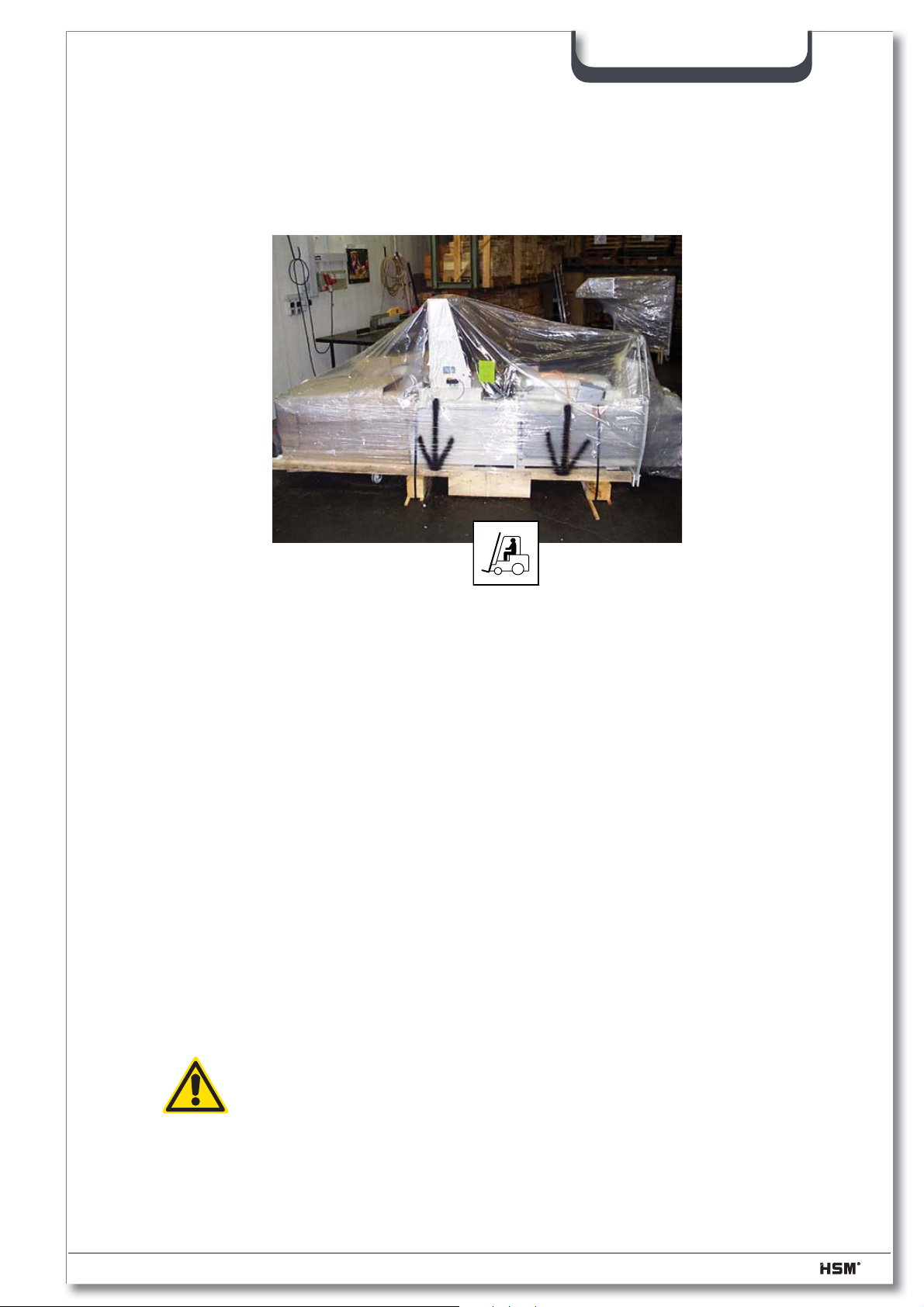
Always use the special bearing points for loading the machine from a lorry using a forklift.
SP 5088
– Place the baling press on a smooth level surface at the installation site.
– Remove the packaging foil and dispose of it in a manner that is environmentally
sound.
– Cut through the steel straps.
– Using a forklift, lift the baling press by approximately 10 cm and remove the wooden
blocks.
– Open the inspection fl ap and remove all the items delivered with the machine from the
press chamber.
3.5.1 Transport to another application site
Over short distances the channel baling press can be rolled to the operating site.
Ensure that the load on the foundation is accounted for and the space requirements
fulfi lled at the new installation site. An approved electrical connection must be available
at the new installation site.
Caution!
Installations on the electrical system or control cabinet may only be carried out by a qualifi ed electrician or one of our service engineers.
07/2013 2.991.999.120_en 21
Page 22
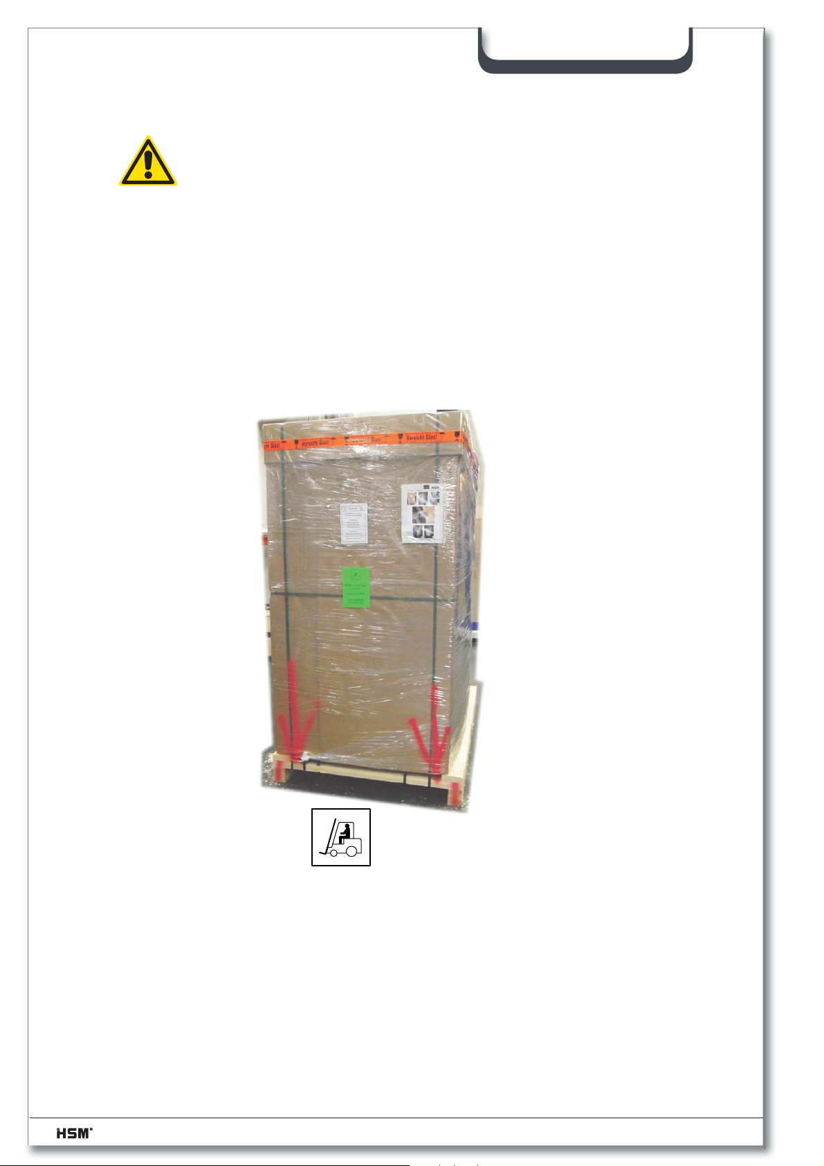
3.6 Transporting the shredder
Caution!
When moving the shredder, note that it may topple over. Danger of
falling over!
– Place the shredder on a smooth level surface at the installation site.
– Remove the packaging foil and dispose of it in a manner that is environmentally
sound.
– Cut through the steel straps.
– Roll the shredder off the pallet in accordance with the unpacking instructions. The
shredder can now be moved on its rollers.
SP 5088
• The loading table must be mounted at the installation site.
22 2.991.999.120_en 07/2013
Page 23
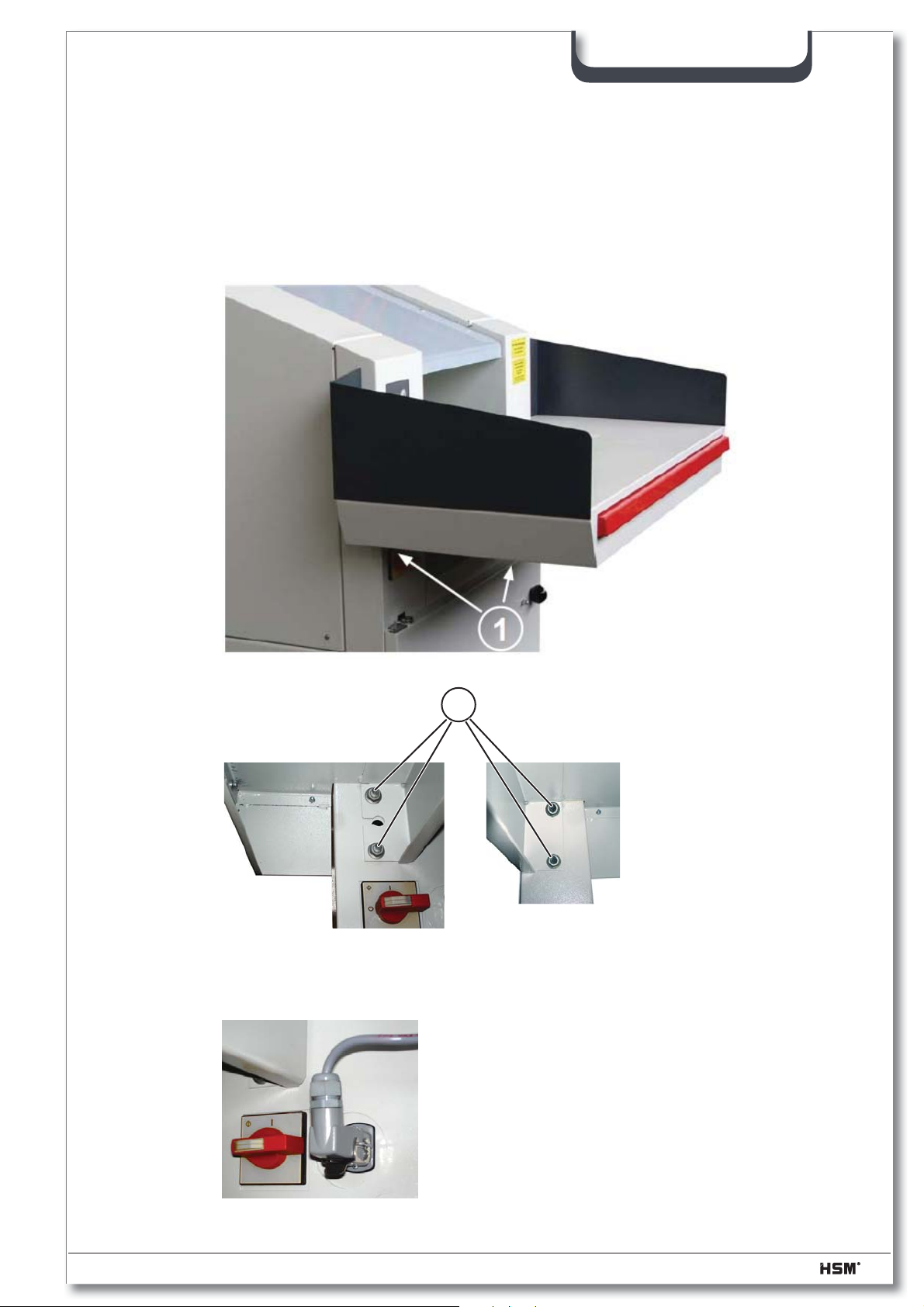
3.7 Assembling the shredder
The shredder is not fully assembled on delivery.
The loading table is not assembled and should only be assembled at the installation site.
- Attach the table using the M10 nuts (1)
SP 5088
1
- Insert the plug (connection for the emergency stop switch bar) into the socket and
turn it to stop.
07/2013 2.991.999.120_en 23
Page 24
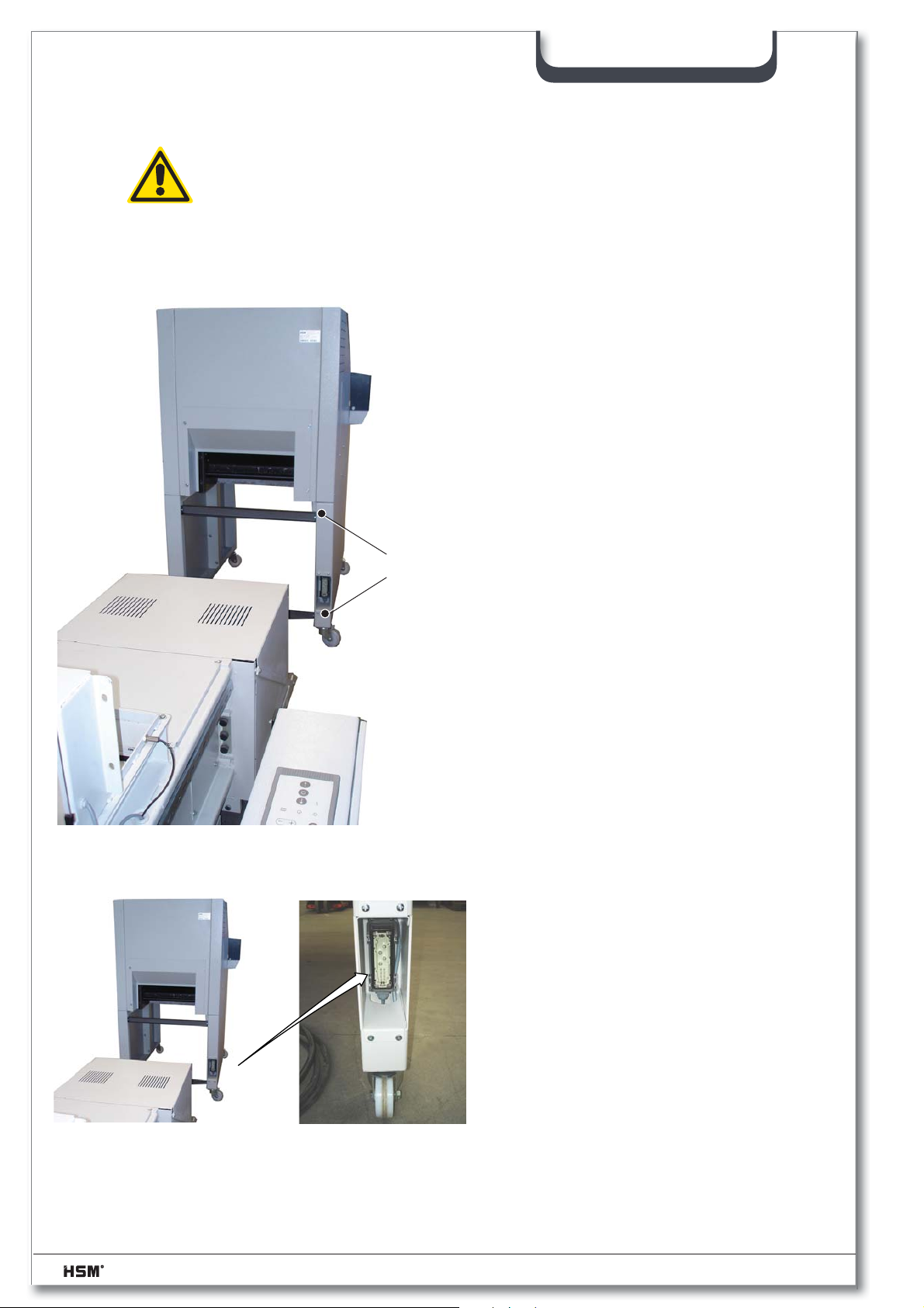
3.8 Assembling the shredder press combination
Danger!
Open shearing point, blade rollers.
Risk of fi ngers and hands being severed.
Neither the shredder nor the combined press may be switched on before
both devices have been properly connected and bolted together!
1. Remove the 2 cross braces (S) on the
shredder and lock the roller brakes on
the press.
SP 5088
S
2. Push the shredder over the press from
behind.
3. Insert the plug of the connection cable
into the socket of the shredder and lock
the plug in position.
24 2.991.999.120_en 07/2013
Page 25
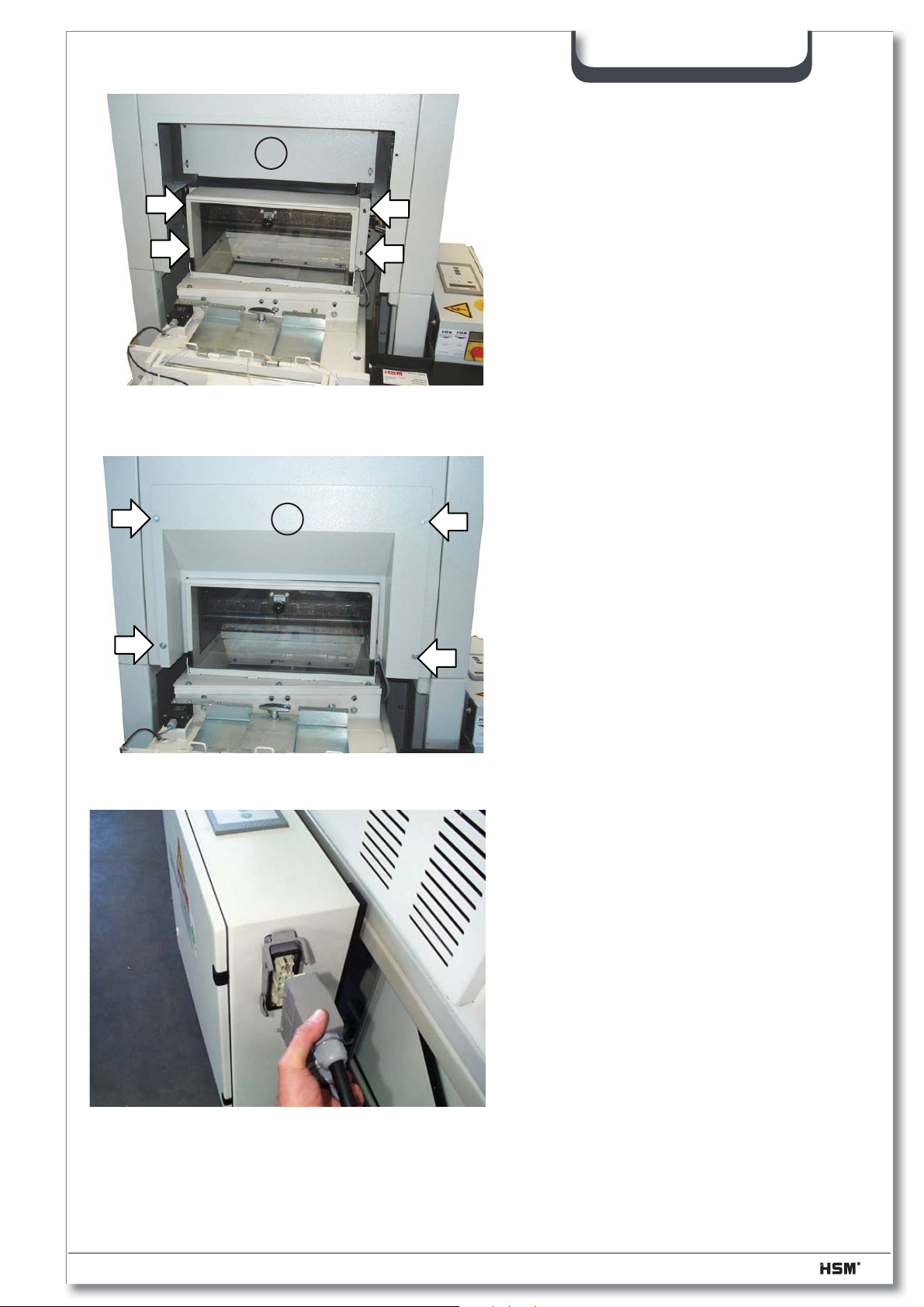
SP 5088
4. Carefully push it forward until the discharge chute of the shredder touches
A
the press hopper. Take care with the
cable whilst doing so.
5. If the Shredder cannot be completely
pushed up against in the press hopper, the cover (A) must be loosened
and subsequently retightened.
6. Bolt the shredder and the baling
press together using the 4 nuts.
7. Attach the cover plate (B) using the 4
fi llister head screws.
B
8. Insert the plug of the connection cable into the socket of the baling press
and lock the plug in position.
07/2013 2.991.999.120_en 25
Page 26
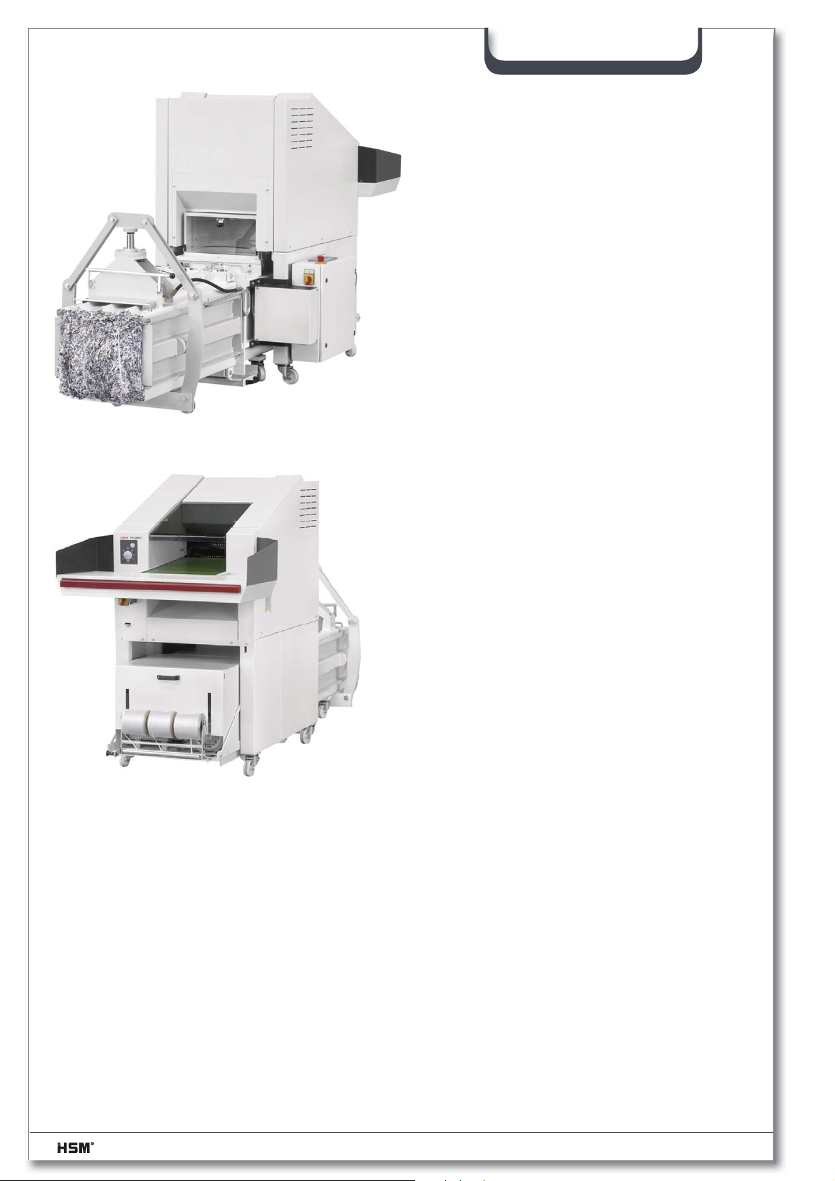
SP 5088
10. Then lock the roller brakes on the shredder.
11. Inspect the safety devices. Use the
checklist in section 1 for the inspection.
26 2.991.999.120_en 07/2013
Page 27
4 Commissioning
SERVICE
ELECTRONIC
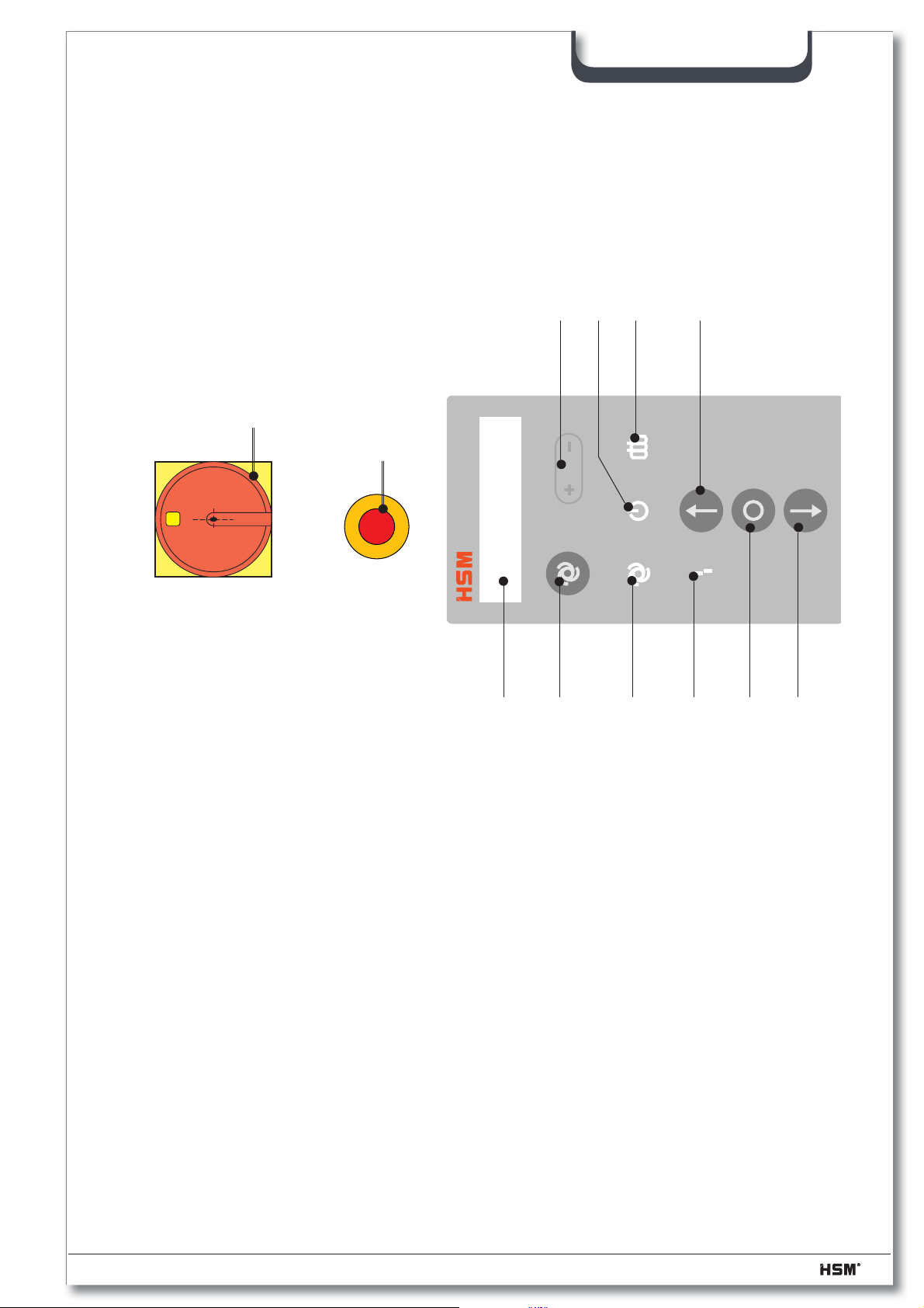
4.1 Baling press controls
SP 5088
0
11
1
I
0
2
12
3
695
7104
8
1 Main switch
2 Emergency stop
3 Automatic mode
4 Automatic mode (LED)
5 Standby (ready indicator)
6 Press ram forward
7 Press ram stop
8 Press ram backward
9 Bale ready
10 Malfunction
11.1 Menu selection / scroll up (+) / down (-)
11.2 Open press channel (+)
12 Text display
07/2013 2.991.999.120_en 27
Page 28
SP 5088
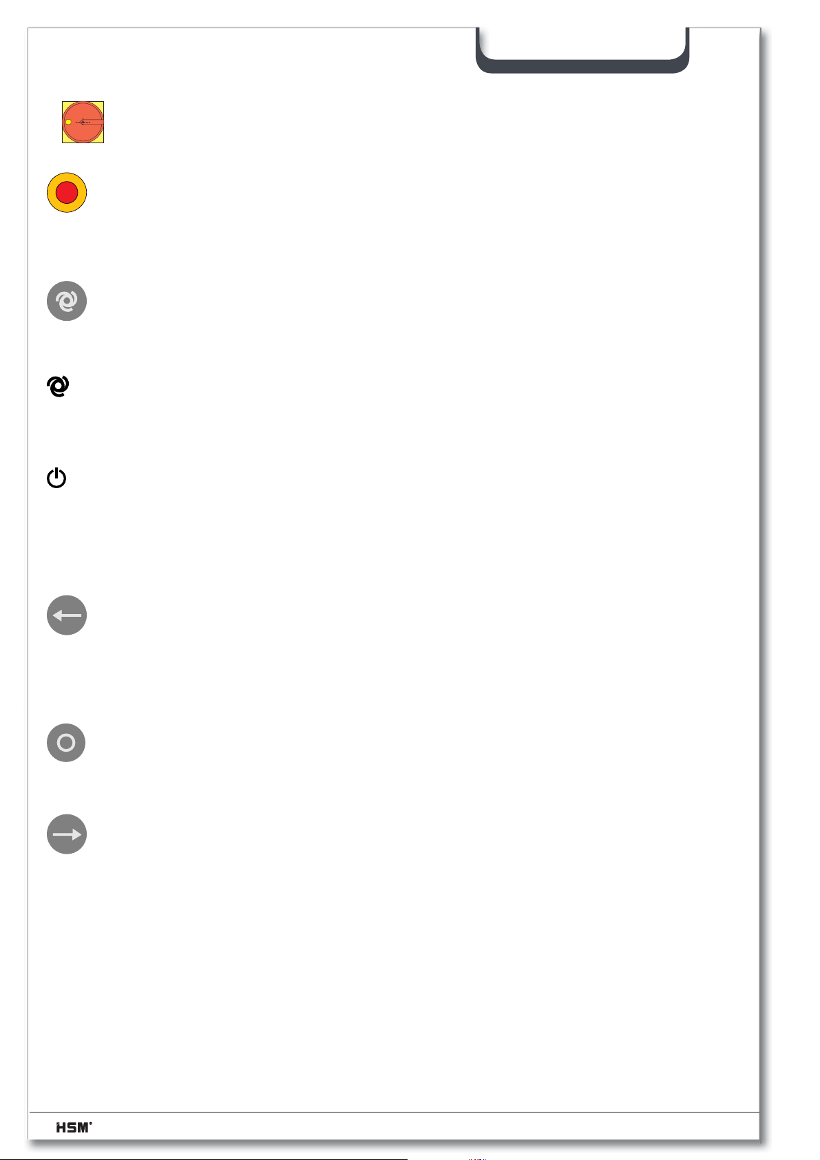
Main switch (1)
I
0
0
The main switch is on when it is turned 90° to the right.
In the “Off” position, the main switch can be secured with a padlock.
Emergency stop (2)
Turn the “Emergency stop” button to the left unlock it.
If you press the “Emergency stop” button the power circuit is broken. This switches
off the baling press and the shredder.
“Automatic mode” key (3)
This key switches the baling press into automatic mode. Deselect the automatic mode by
pressing the key again.
“Automatic mode” LED (4)
This symbol lights up yellow as soon as the automatic mode is switched on.
“Standby” LED (5)
This symbol lights up green as soon as the main switch is switched on and the machine
receives power.
This symbol fl ashes in the set-up mode or with the “Bale ready” message
“Press ram forward” key (6)
(arrow in direction of pressing)
This key starts the press cycle. The press ram moves forward and presses the material.
After the compression time has expired, the press ram automatically moves to the rear
limit position. The motor switches off.
“Stop press ram” key (7)
This key is used to stop the press ram in any position.
“Press ram backward” key (8)
(arrow opposite direction of pressing)
This key moves the press ram back to the rear limit position.
28 2.991.999.120_en 07/2013
Page 29
SP 5088
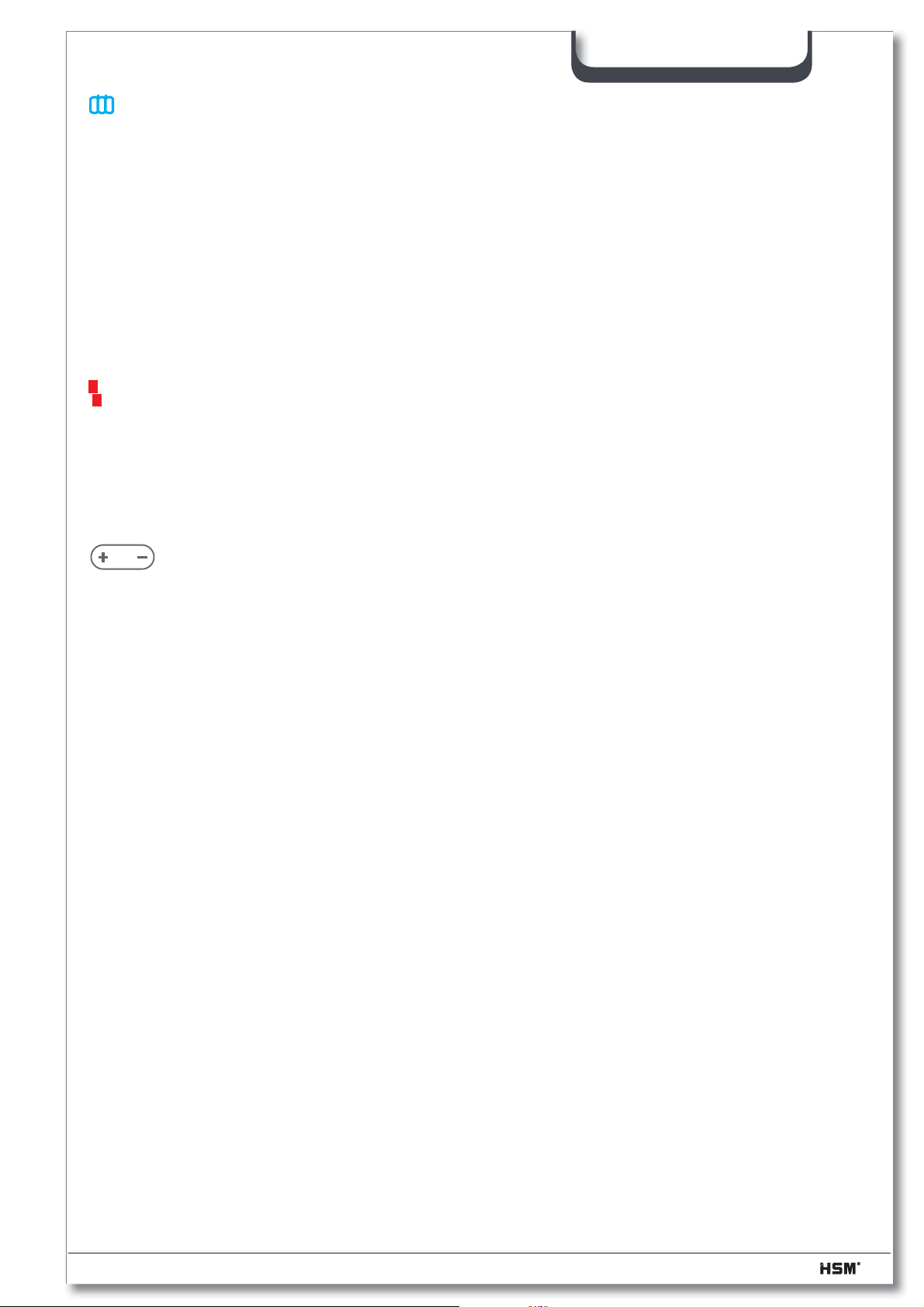
“Bale ready” LED (9)
This symbol lights up blue as soon as the bale has reached a set size. The press ram
stops, and the press and shredder switch off.
Indicator: Bale ready
2-hand control
The “Press ram status” symbol lights up yellow on the shredder control panel. The cutting
unit of the shredder can now only be run backwards.
The “Bale ready” message remains active until the counter plate is closed. Then the
Indicator: Manual mode
Bale number: xxx (= daily bale meter reading) appears.
“Malfunction” LED (10)
This symbol lights up red as soon as a malfunction occurs in the baling press. The press
and shredder switch off.
(-> see also “Malfunctions”)
The machine cannot be started whilst this message is active!
+ / – Keys (11.1)
Press the +/– keys to scroll through the menu items.
See also the following pages.
+ Key (11.2)
Pressing this button + will open the bale channel and pressure-relieving
Text display (12)
The text display shows the operating conditions and error messages.
(-> see also “Malfunctions”)
07/2013 2.991.999.120_en 29
Page 30
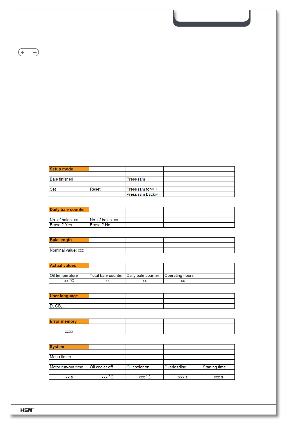
4.1.1 Accessing the SERVICE menu
SERVICE
Service menu / + / – Keys (11)
The service menu can only be called up in manual mode.
Simultaneously press the +/– keys for approx. 3 seconds to access
the Service menu item
Use the +/– keys to scroll through the sub-menu items
Setup mode - Daily bale counter - Balen length - Actual values - User language Error memory - System
Simultaneously press the +/– keys again for approx. 3 seconds whilst in the relevant submenu item, to gain further access within these menus.
Press the +/– keys to scroll through the menus.
Simultaneously press the +/– keys to confi rm the values set.
Press any key to return to the main menu.
SP 5088
30 2.991.999.120_en 07/2013
Page 31

SP 5088
4.1.1.1 Select setup mode (Bale fi nished / press channel / press ram)
– Simultaneously press the +/– keys for approx 3 seconds
Indicator: Service menu
Setup mode
– Simultaneously press the +/– keys for approx 3 seconds
Indicator: Setup mode
Bale fi nished
– Simultaneously press the +/– keys for approx 3 seconds
Indicator: Bale fi nished
setting
– Scroll to the desired menu items using the +/– keys
set / reset
– Simultaneously press the +/– keys for acknowledgement
– Simultaneously press the +/– keys for approx 3 seconds
Indicator: Service menu
Setup mode
– Simultaneously press the +/– keys for approx 3 seconds
Indicator: Setup mode
Bale fi nished
– Press the + key 1x
Indicator: Setup mode
Press ram
– Simultaneously press the +/– keys for approx 3 seconds
Displayanzeige: Press ram forward +
Press ram backward -
– Pressing the + key you can move the press ram forwards in inching operation
– Pressing the – key you can move the press ram backwards in inching operation
07/2013 2.991.999.120_en 31
Page 32

4.1.1.2 To display / clear the daily bale meter
– Press the +/– keys simultaneously for about 3 seconds
Indicator: Service menu
Setup mode
– Press the + key 1x
Indicator: Service menu
Bale/day
– Press the +/– keys simultaneously for about 3 seconds
Indicator: Bale count xxx
clear? yes/no
– Use the +/– keys to scroll to the required menu item
clear yes / clear no
– Press the +/– keys simultaneously to confi rm
SP 5088
4.1.1.3 Displaying / adjusting: Bale length or No. of strokes
Note
Bale length -> for baler with counting wheel
No. of strokes -> for baler without counting wheel
The options are set via DIP switches.
– Press the +/– keys simultaneously for about 3 seconds
Indicator: Service menu
Setup mode
– Press the + key 2x
Indicator: Service menu
Bale length or No. of strokes
– Press the +/– keys simultaneously for about 3 seconds
Indicator: Bale length Nominal value xxx
– Scroll to the desired bale length using the +/– keys (200 mm ÷ 950 mm)
– Scroll to the desired no. of strokes using the +/– keys (3 ÷ 20 compression strokes)
(values adjusted by HSM: bale length 500 mm / no. of strokes is depending on
material)
– Simultaneously press the +/– keys for acknowledgement
32 2.991.999.120_en 07/2013
Page 33

4.1.1.4 Displaying / adjusting the actual values
– Simultaneously press the +/– keys for approx 3 seconds
Indicator: Service menu
Setup mode
– Press the + key 3x
Indicator: Service menu
Actual values
– Simultaneously press the +/– keys for approx 3 seconds
Indicator: Oil temperature
xxx°
– Scroll to the desired menu items using the +/– keys
Total bale counter / Daily bale counter / Operating hours
Indicator: Total bale counter
xxx
or
Indicator: Daily bale counter
xxx
or
Indicator: Operating hours
xxx
SP 5088
4.1.1.5 Adjusting the user language
The screen display can be adjusted for different user languages.
The following ones are available:
D - GB - F - E - I - P - NL - N - S - FIN - DK - GR - TR - PL - CZ - RUS
– Simultaneously press the +/– keys for approx 3 seconds
Indicator: Service menu
Setup mode
– Press the + key + Taste 4x
Indicator: Service menu
User language
– Simultaneously press the +/– keys for approx 3 seconds
Indicator: User language
D
– Scroll to the desired language using the +/– keys
– Simultaneously press the +/– keys for acknowledgement
Indicator: Manual operation
Nominal xxx Actual xxx
07/2013 2.991.999.120_en 33
Page 34

4.1.1.6 To display the error memory
For diagnostic purposes, the most recent error is stored in the error memory. For error
numbers, see the section “Malfunctions”
– Press the +/– keys simultaneously for about 3 seconds
Indicator: Service menu
Setup mode
– Press the + key 5x
Indicator: Sevice menu
Error memory
– Press the +/– keys simultaneously for about 3 seconds
Indicator: Error memory
xxxx
SP 5088
4.1.1.7 System
This menu item is only available to HSM service technicians.
34 2.991.999.120_en 07/2013
Page 35
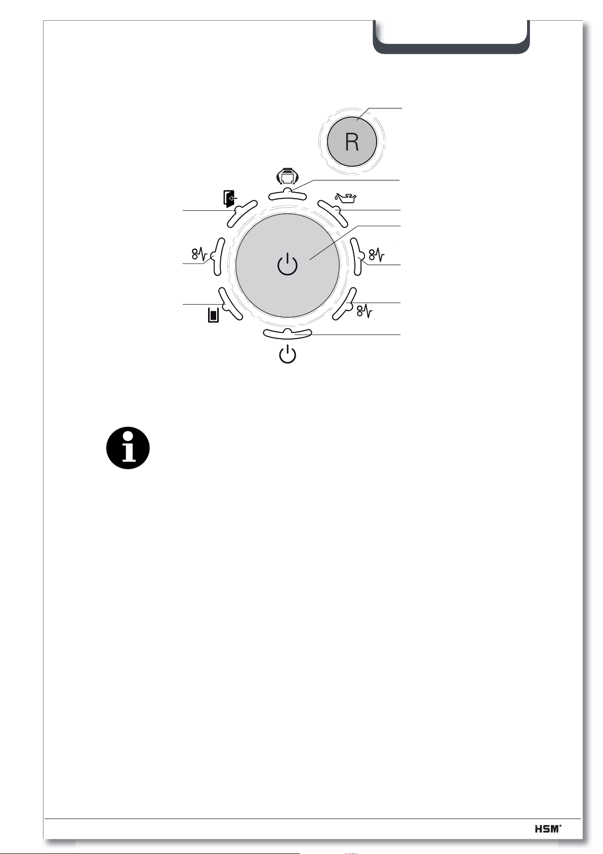
4.2 Shredder control panel
SP 5088
R button:
Cutting unit runs in reverse
Display: Status of the
baling press
Display: Door open or
emergency stop activated
Display: Level 1
overload
No function
Display: Oil reservoir empty
Function button
“On / off / start”
1
Note
The shredder can only be operated, whilst the press is in
automatic mode.
2
Z
Display: Level 2 * overload
No function
Display: Ready for operation
4.2.1 Display: Baling press not in automatic mode
This symbol lights up red, if the press is not in automatic mode.
4.2.2 Display: Status of the baling press
This symbol lights up
green, whilst the press is in automatic mode.
yellow, when the bale is ready for strapping.
red, if a malfunction occurs in the baling press.
07/2013 2.991.999.120_en 35
Page 36
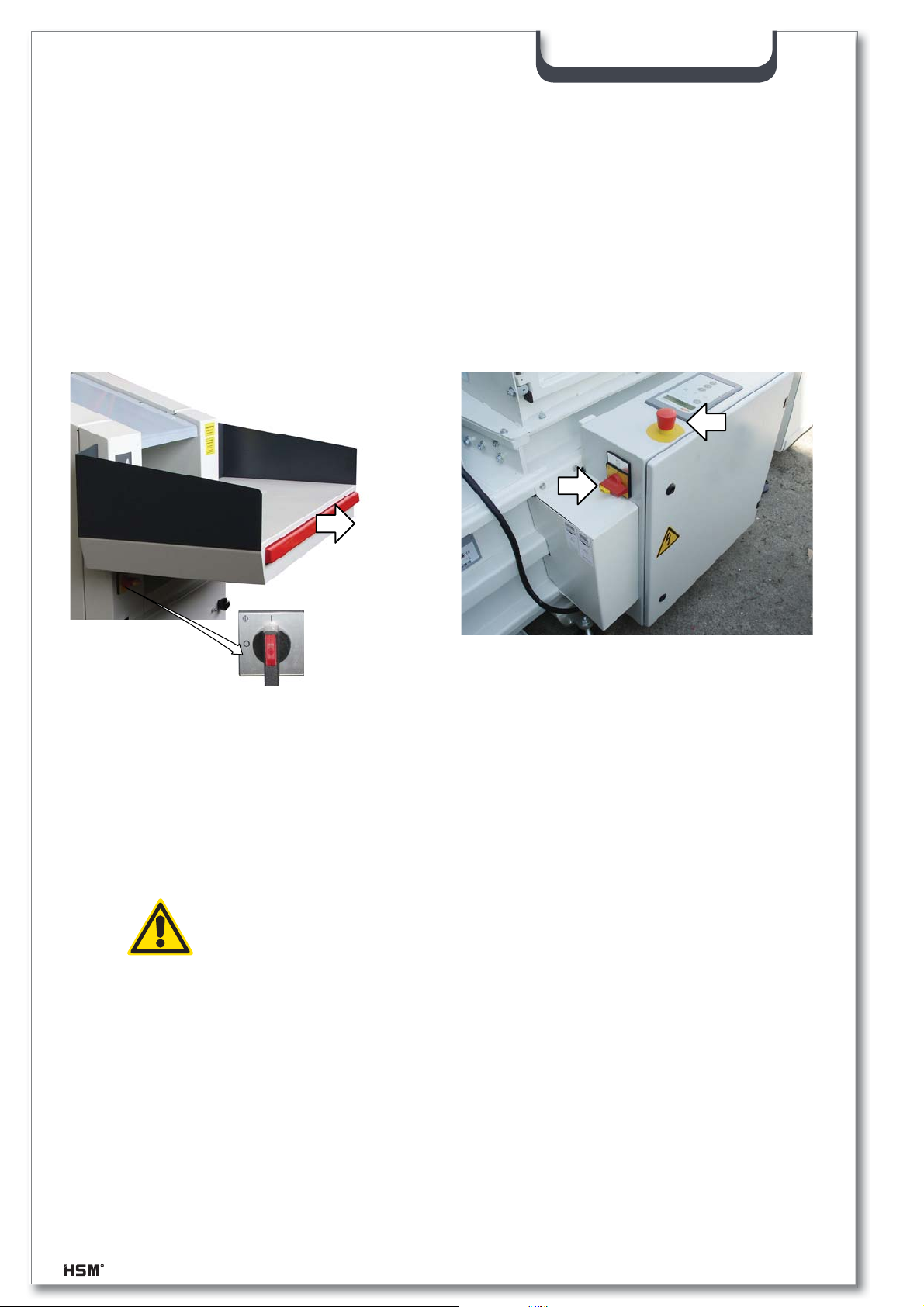
4.3 Initial start-up
– Open the inspection door on the hopper and check that the press chamber is clear, and re-
move any spare parts or supplies delivered with the machine
– Insert the CEE Plug into the socket on site.
– Activate the emergency stop control by pushing the switch bar away from the machine.
– Unlock the emergency stop on the press.
– Switch on the main switch of the press and the shredder.
SP 5088
• After a self-test by the control, the
Indicator: Manual mode
Norminal xxx Actual xxx
– If the error number 1000 (= phase is absent) or 1010
(= counter-clockwise phase rotation) appear in the display -> call an electrician!
See also the “Malfunctions” section
Warning!
Faults in electrical components and supply cables may only be attended
to by qualifi ed electricians or HSM service engineers.
– Close the control cabinet, before continuing to commission the machine.
– Set the desired user language
– Set the desired barrel length or number of strokes of the press cylinder
Factory set value: body length 500 mm / stroke rate depends on the material
36 2.991.999.120_en 07/2013
Page 37
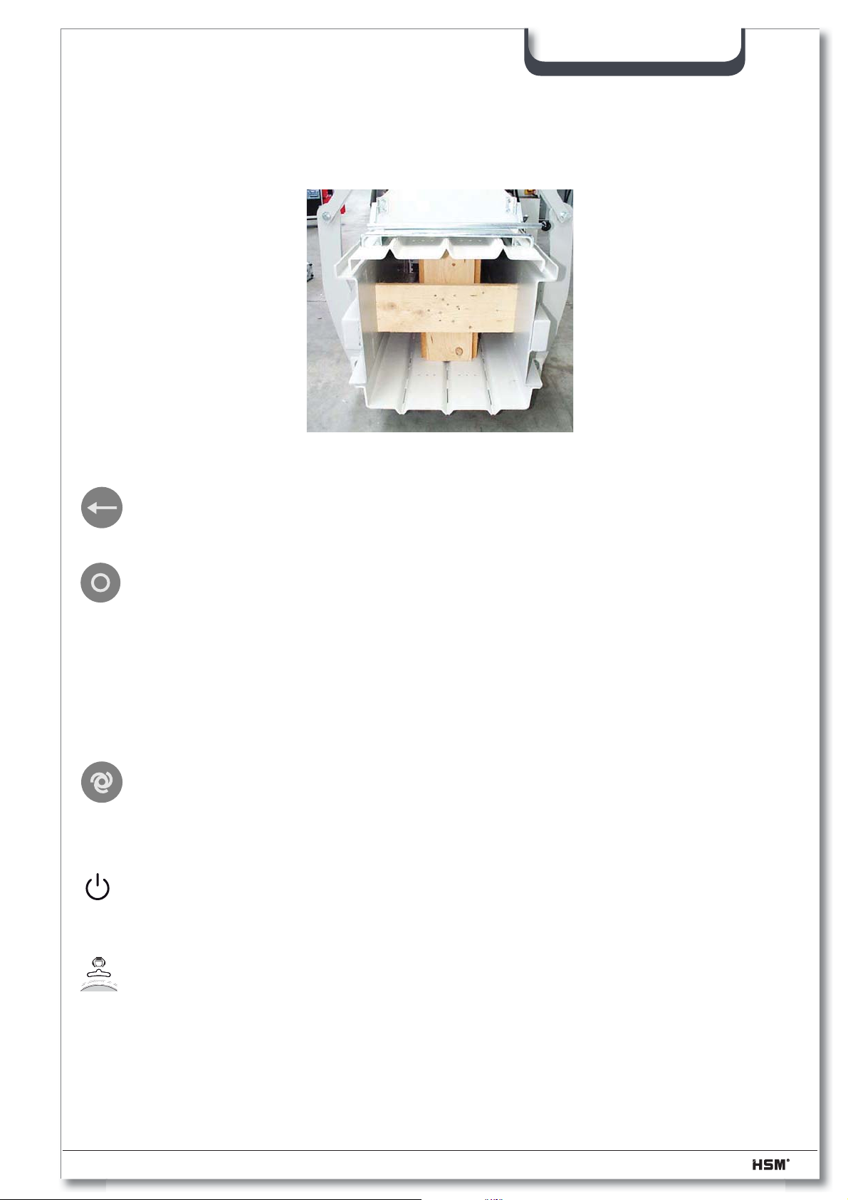
4.4 Running in the baling press
– Place the wooden frame (460 mm x 460 mm square timber: 120 mm x 120 mm) into
the press channel
SP 5088
– Press the "Press ram forwards" key (arrow in compression direction)
• the press ram moves forwards , automatically reverses and stops in its start position
• pressing the stop-key stops the movement of the press ram at any position; the
movement can be continued by pressing the "Press ram forwards" or "Press ram
backwards" keys
– Move press ram approx. 2 times forwards and backwards in manual operation
• This braces the wooden frame in the press channel (this step is required only when the
press channel had been disassembled or the wooden frame had not yet been braced)
– Press the "Automatic operation" key on the baling press
• white light symbol "Automatic operation" comes up
Indicator: Automatic operation
Nominal xxx Actual xxx
• Display "Ready" light green at the shredder.
• Display "mode of the baler," the shredder is green.
07/2013 2.991.999.120_en 37
Page 38
SP 5088
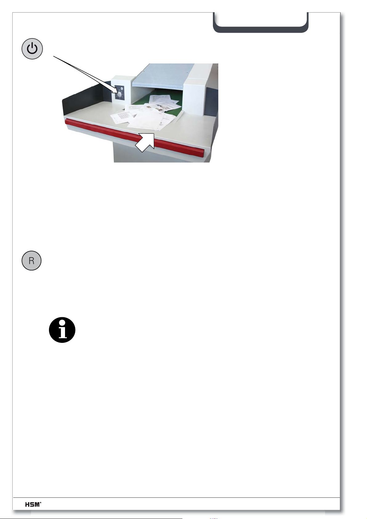
– Press the start button
• The cutting unit and feed belt start up
– Place the material to be shredded on the loading table and then place batches on
the infeed conveyor
If material that is not supposed to be shredded is mistakenly placed onto the conveyor
belt do not try to pull it out, but
– Press the start button again
• The cutting unit and feed belt stop
– Press the R-button
• The cutting block and feed belt run in reverse
– When you release the R button, the shredder will be stop
– You can now remove the material from the belt and start the shredder again by
pressing the start button
Note
Provided the cutting unit is running in the shredding direction, you can
stop it by pressing the R button.
The shredded material falls through the discharge chute of the shredder directly into the
hopper of the press.
The press cycle is initiated by the light barrier inside the hopper when a certain fi lling
level is reached. The press ram moves forwards and compresses the material. The
press ram automatically returns to its rear end position after expiry of the pressing time.
The shredder continues running during the press cycle.
– Feed the paper shredder with material until the wooden frame is ejected at the end
of the press channel during the compression process
– Switch off the main switch on the baling press
– Draw in the 3 strapping tapes (as described in section 4.5)
38 2.991.999.120_en 07/2013
Page 39
SP 5088
Note
The fi rst bales compressed during the running-in of the baling press are
not yet perfectly compressed and shaped. Even compressing the
ejected compression material again does not result in an optimum bale.
– Switch on the main switch on the baling press
– Reload the unstrapped "running-in material" from the beginning through the inspection
fl ap into the baling press
– Close the inspection fl ap
– Press the "Press ram forwards" key and compress all "running-in material" in this
manner
– Press the "Automatic operation" key
– Following you can continue working automatically with the equipment
4.4.1 Setting the press channel adjustment cylinder
The material is compressed and pushed into the conical press channel. The press
channel opens and closes depending on the pressure.
The opening speed of the press channel can or must be adjusted depending on the type
of material to be pressed (frictional resistance).
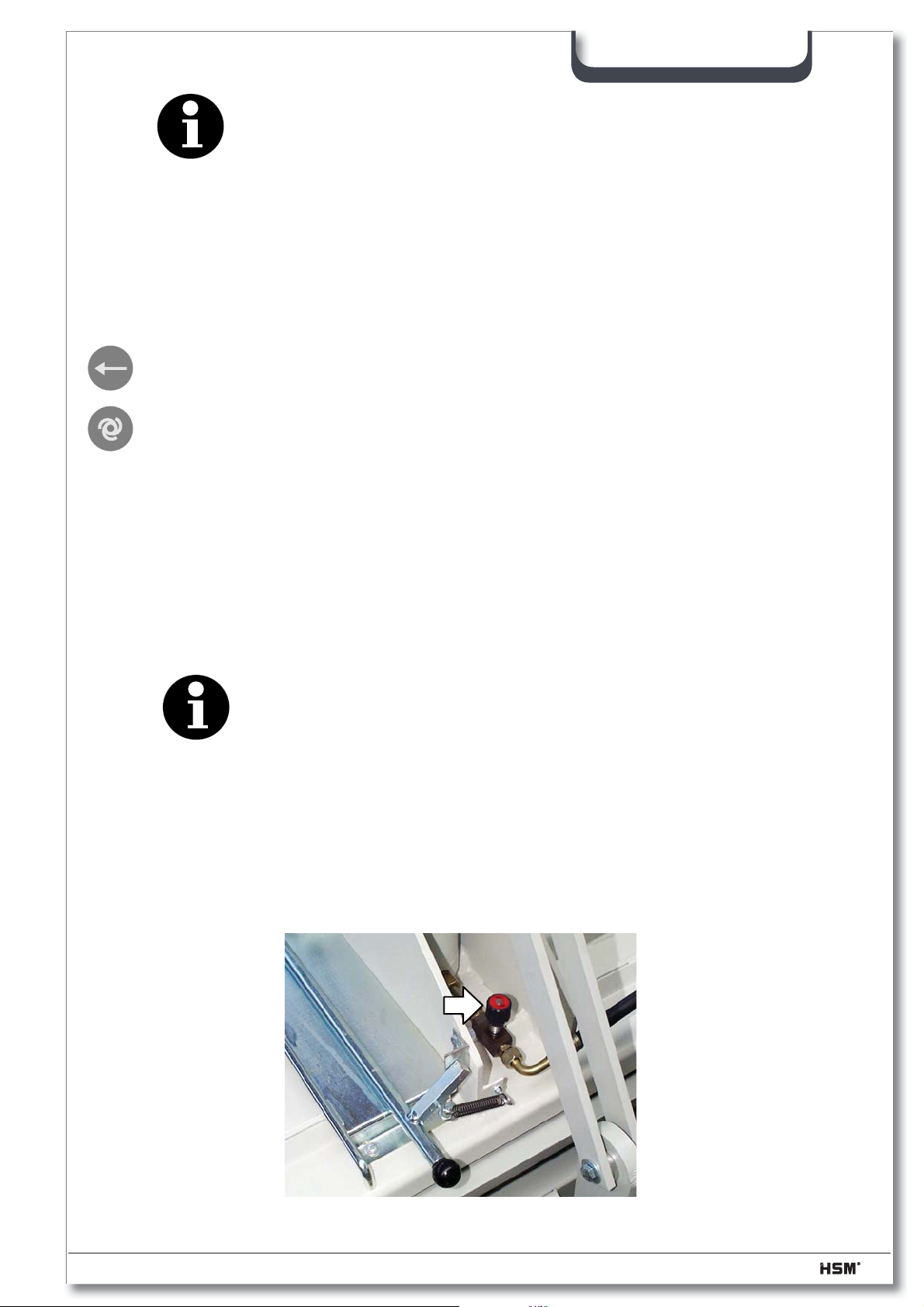
Note
The press channel should open smoothly – not with a sudden jerk!
Close the throttle screw to open the press channel more slowly
Open the throttle screw to open the press channel more quickly
Basic setting:
Close the throttle screw completely and open it by 1/8 of a turn.
07/2013 2.991.999.120_en 39
Page 40
4.4.2 Relieve the press channel
The press channel is to be relieved:
a) before starting maintenance works
b) if the press channel has to be emptied or disassembled
c) if the pressing force of the press cylinder is not suffi cient to shear off the material or to
press the material into the tape repress channel. (shearing malfunction)
– Press the "Open channel" push button
• the press channel is relieved, that means the adjustment cylinder lowers.
Note
This is valid either for manual and automatic operation.
It's also possible to relieve the press channel during operation.
SP 5088
40 2.991.999.120_en 07/2013
Page 41
4.5 Drawing in the strapping tape
SP 5088
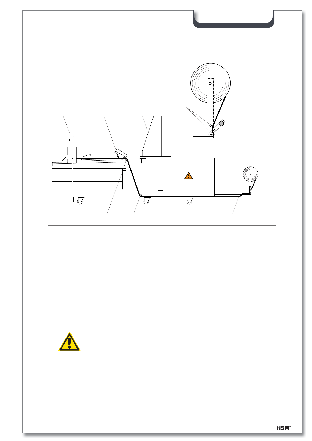
9
– Open the strapping fl ap (1) and the inspection door (2) on the hopper
– Pull the strapping tape (4) from the roll
1
8
2
5
67
3
4
– Open the tape brake (3) and pull the strapping tape through the bore hole (5)
– Push the strapping tape into the tube (6) until the tape comes out at the front of the
press chamber (7)
– Pull the strapping tape upwards and through the eyelet (8)
– Pull the strapping tape forwards up to the press channel adjustment (9) and let it be
placed upon the cover, so that the tape can run on when the new bale is compressed
Caution!
Do not tie the tape end to the press channel because this can tear the
tape off!
– Close the strapping fl ap
– Take up the loose tape on the tape roll and close the tape brake
07/2013 2.991.999.120_en 41
Page 42
4.6 Automatic compression with light barrier
– Press the "Automatic operation" key
• yellow light symbol "Automatic operation" comes up
Indicator: Automatic operation
Nominal xxx Actual xxx
– Now you can start feeding the paper shredder continuously
In this setting, the press ram automatically moves forwards and backwards until the
beam of the light barrier is interrupted by compression material.
After the set bale length has been reached, the message "Bale fi nished - Strapping" is
displayed and the press ram stops in its foremost position.
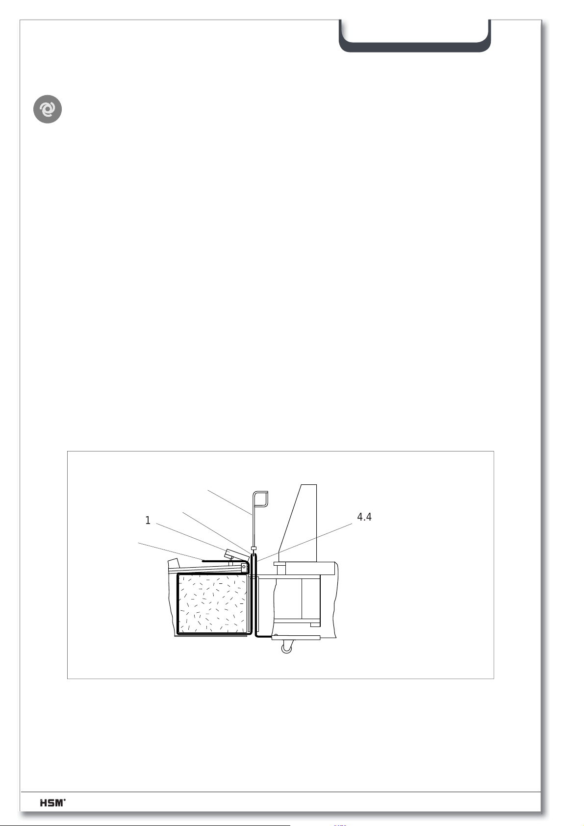
4.7 Strapping procedure
SP 5088
The press ram moves into its front position and stops in "Strapping" position under
pressure. The bale must now be strapped three times. Proceed as follows:
– Open the strapping fl ap (1) and loosen the tape brake
10
4.3
1
4.5
4.4
– Check whether the channels in the press ram are free from material and clean the channels
using the tape insertion needle (10), if necessary
42 2.991.999.120_en 07/2013
Page 43
SP 5088
– Push down the tape insertion needle (10) through the fi rst strapping channel of the press
ram
– When the tape insertion needle is rotated by 90°, the catching claw grips the loose tape
– Pull the hooked-in strapping tape up and put the tape insertion needle to the side
– Cut the tape loop with a knife or a pair of scissors and knot the tape ends (4.5) and (4.3)
Note
Make sure that you do not mix up the tape ends (4.3) and (4.4)!
Bale strapping is then impossible!
– Pull the cut tape (4.4) immediately through the respective lugs up to the press channel
adjustment.
Caution!
Do not tie the tape end to the press channel because this can tear the
tape off!
– Repeat this process for the 2nd and 3rd strapping process
– Close the strapping fl ap (1) and the tape brake
Warning!
If the channels in the press ram are not cleared carefully, it could cause
that a tape will be caught in the press ram and pulled in by the reverse
movement of the press ram.
Never hold tight a tape with your hands, that is pulled in!
Squeezing and cutting injuries could be the result.
– The compression can now be initated again with the "Automatic operation" key or
manually with the "Press ram forwards" key
07/2013 2.991.999.120_en 43
Page 44
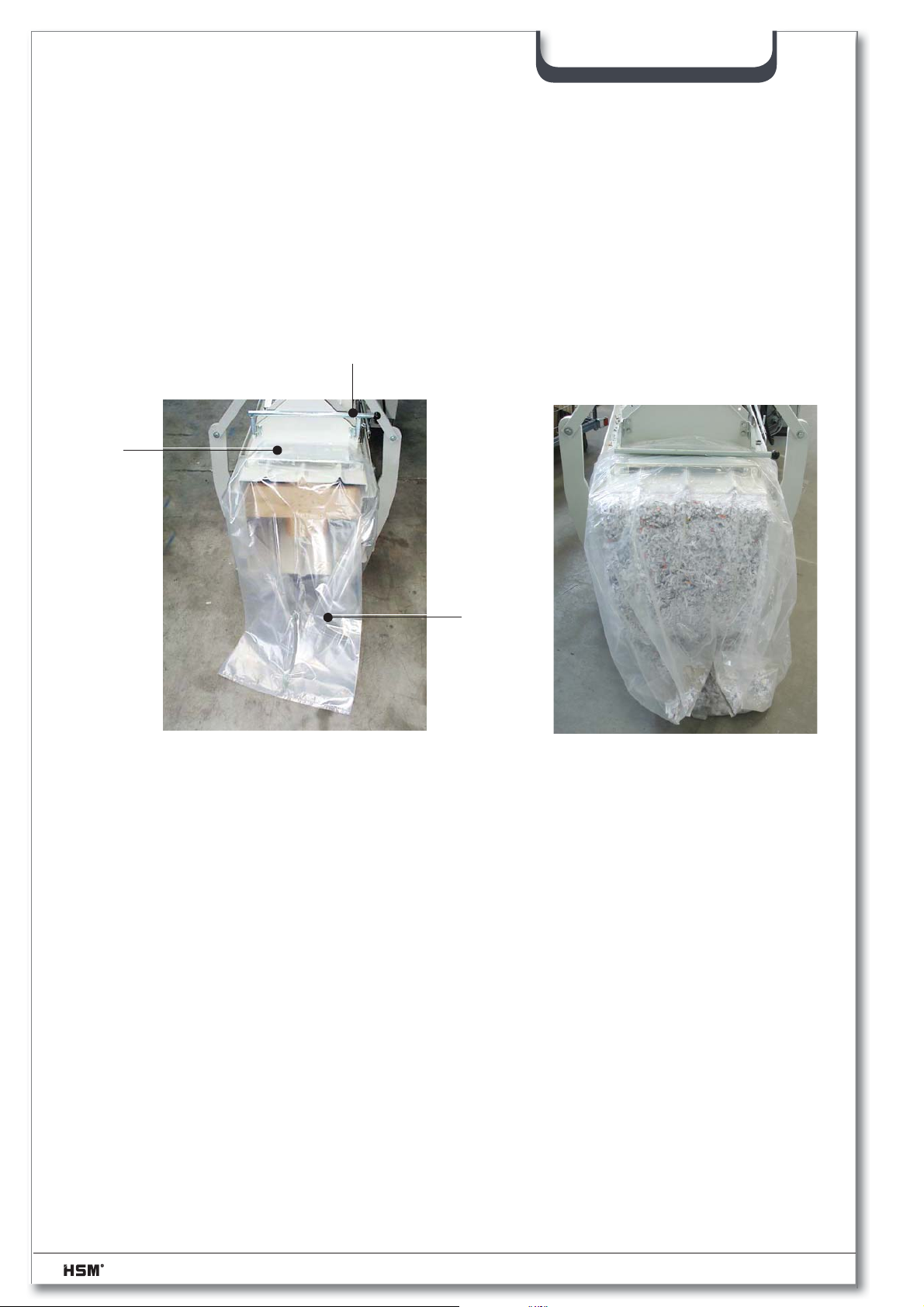
4.8 "Sacking" procedure
– Lift the tension lever (11)
– Pull the plastic sack (12) over the outlet opening and push it further on over the metal
sheet (13)
– Lower the tension lever (11)
• the ready bale is automatically pushed into the plastic sack.
13
SP 5088
11
12
Accessories:
Plastic sack Order no.: 1 452 995 000
44 2.991.999.120_en 07/2013
Page 45
4.9 Malfunctions of the baling press
As soon as a malfunction occurs in the baling press, the red malfunction symbol lights
up. The baling press and shredder switch off and the relevant error message appears in
the text display.
SP 5088
The “Baling press status” symbol
lights up red on the shredder.
The error number of the most recent error is stored in the error memory.
Diverse, displayed error messages can be cleared by simultaneously pressing the + / –
keys or by turning the machine on and off.
Service - Hotline: +49 7544 2100-300
4.9.1 Error numbers
Code Description Remedy
1000 One of the phases is missing / power input Electrician! Check the fuses on site.
1010 A phase is wrong / counter-clockwise phase
rotation
1100 Oil temperature too high Let oil cool down
1110 Defective oil temperature sensor Electrician! Replace sensor
1200 Motor protective switch has triggered off Let Motor cool down - ~ 20 min. waiting
1201 Motor protective switch oil cooler has triggered
off
1210 Emergency stop on the press has been activated Unlock the emergency stop button
1211 Emergency stop on the shredder has been
activated
1222 Service door in the fi lling area of the press is
open
1223 Strapping fl ap is open Close strapping fl ap
1271 “Extend press ram” timing Check the movement of the press ram
1272 “Retract press ram” timing Check the movement of the press ram
1273 Shearing malfunction Remove material jam
1274 Compression malfunction Check channel adjustment
1282 Inductive switch channel adjustment Electrician! Check inductive switch
1290 Light barrier compression/material bridge Remove material bridge / clean light barr.
1291
1300 Defective hardware Electrician! Consult HSM customer service
1310 Short-circuit master output stage Electrician! Consult HSM customer service
1320 Short-circuit slave output stage Electrician! Consult HSM customer service
Light barrier overcharging/material bridge (option)
Electrician! Phase sequence on site / check phase
rotation.
Let Motor cool down - ~ 20 min. waiting
Unlock the emergency stop button
Close the inspection fl ap
Remove material bridge / clean light barr.
07/2013 2.991.999.120_en 45
Page 46
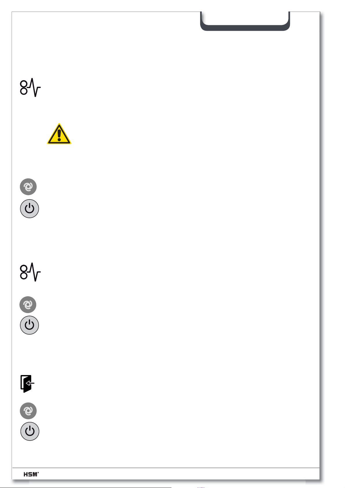
4.10 Malfunctions of the shredder
4.10.1 Overload due to paper jam
• “Overload” display (level 1 or level 2 – depending on the machine model)
lights up red.
• The drive automatically runs in reverse for several seconds. Then the cutting unit
switches off..
Caution!
The blade rollers can still cause injuries even while they are not running.
Do not reach into the cutting unit!
Protective gloves should be worn at all times.
Do not repetitively run the cutting unit backwards and forwards, for the
purpose of removing an obstruction. This will damage the shredder.
- Remove the stack of paper.
- Press the automatic button on the press
- Press the start button and put less paper on the feed belt.
SP 5088
4.10.2 Electric motor overheats
• “Overload” display (level 1 or level 2 – depending on the machine model)
fl ashes red.
• The drive automatically switches off.
- Let the motor cool down for 20–30 minutes.
- Press the automatic button on the press
- Press the start button.
4.10.3 Emergency stop activated
• Display lights up red.
• The baling press and shredder switch off.
- Activate the emergency stop control by pulling the switch bar away from
the machine.
- Press the automatic button on the press
- Press the start button.
46 2.991.999.120_en 07/2013
Page 47
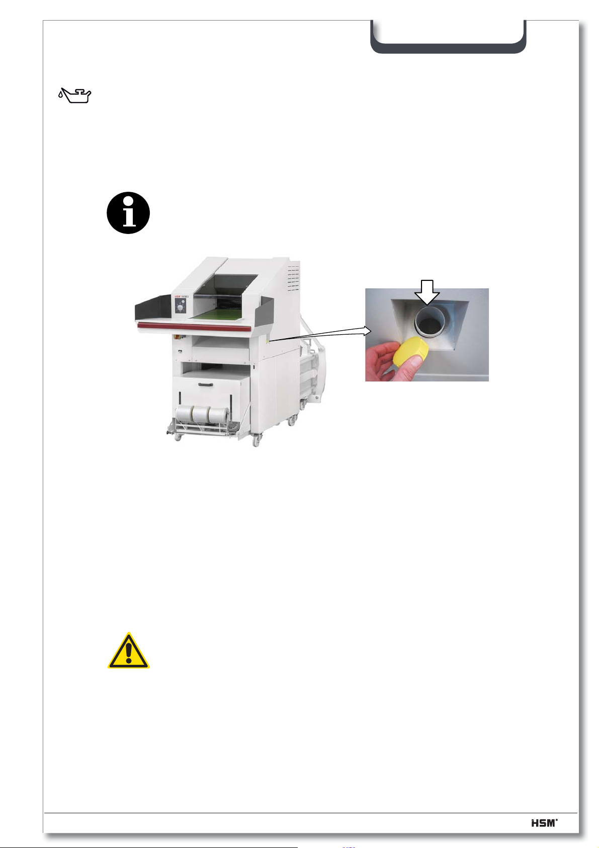
4.10.4 Oil reservoir empty
• “Oil reservoir empty” display lights up blue.
- Refi ll the the cutting block special oil.
Order no. 1.235.997.500 for a 5 l container
• After the reservoir is fi lled, the “Oil reservoir empty” signal is automatically
deactivated.
Note
The shredder remains operational even when the oil reservoir is empty.
SP 5088
4.11 Stopping the machine
- Run the machine into the initial position (with the press ram at the rear)
- Switch off the main switch of the shredder and of the press
- Secure the main switches against restarting
- Unplug the red CEE power plug
4.12 Outdoor use
Warning!
For reasons of safety, only operate under supervision. The operator
must ensure that unauthorized persons do not have access to the ma-
chine.
When the machine is not being used, it must be shut down and
secured against unauthorised use.
See also the “Siting the machine” section
07/2013 2.991.999.120_en 47
Page 48
5 Inspection and maintenance work
5.1 Notes on maintenance
Note
Malfunctions which are due to inadequate or incorrect maintenance can
lead to expensive repairs and lengthy machine down-times.
Regular maintenance is therefore essential.
For this reason we recommend a maintenance and inspection contract.
Warning!
Correct any damage immediately.
Escaping oil can cause fi re and injury!
Maintenance and repair work on the electrical system or control cabinet
may only be carried out by a qualifi ed electrician or one of our service
engineers
SP 5088
All the inspection and maintenance tasks listed here apply to single-shift operation.
The intervals must be reduced accordingly for multiple shift operation. The baling press
must undergo a complete overhaul at least every two years.
Always refer to the “Safety” section during maintenance and inspection work.
Before performing such tasks make sure the drives and additional mechanisms of the
baling press cannot be switched on unintentionally. Turn the main switch to the “0” position
and secure it. Unplug the red CEE power plug.
Maintenance work may only be carried out by our specialist engineers or specially
trained staff.
Only persons with the appropriate skills and experience in hydraulics may carry out work
on the hydraulic equipment.
Empty the press channel before performing repair or maintenance work on the baling
press
48 2.991.999.120_en 07/2013
Page 49
5.2 Maintenance of the baling press
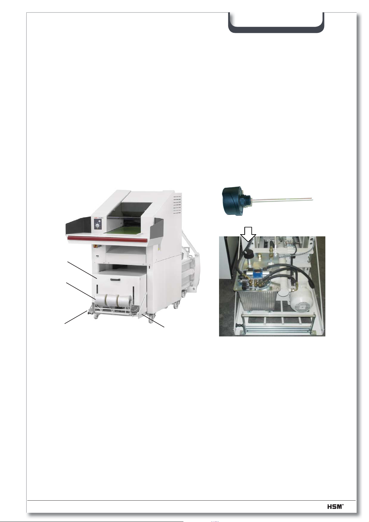
5.2.1 Changing the hydraulic fl uid / venting fi lter
Change the hydraulic fl uid and the venting fi lter every 2 years
– Run the press ram to its rear limit position
– Turn off the main switch and disconnect the red CEE power plug
– Screw off the 2 srews on both sides of the cover (1)
– Take out the spindle (2) with the tape rolls and put it on the ground
– Remove the cover (H)
SP 5088
Venting fi lter
Part. no. 6.116.195.090
H
2
1
– Remove the tank cover and extract the oil with an oil suction unit
• The capacity of the hydraulic fl uid tank is ~ 27 l
– If the tank is very dirty, clean it
– Mount the tank cover onto the unit again
– Add oil until a level between the notches on the oil level dipstick is reached
1
07/2013 2.991.999.120_en 49
Page 50
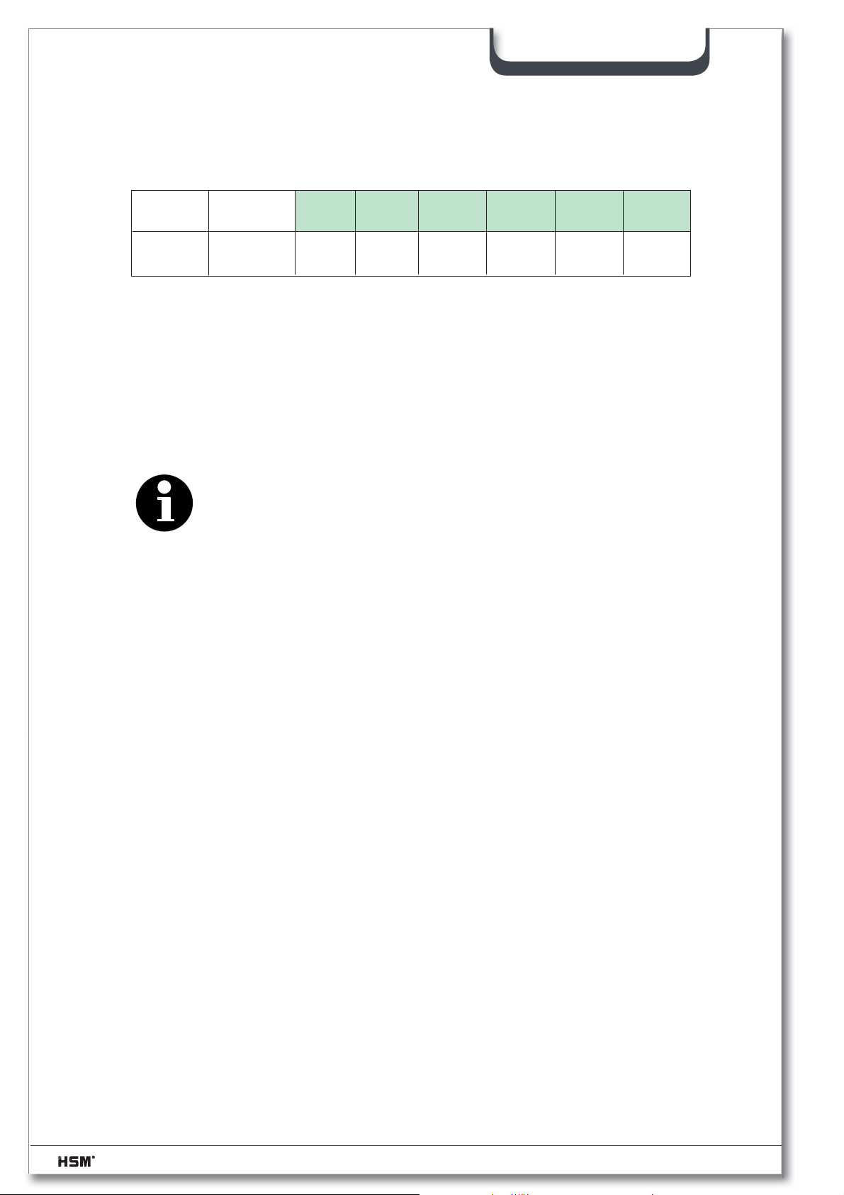
SP 5088
Mineralöle
Mineral oils
ISO VG 22
HVLP
ISO-
Viskositäts-
klasse
ARAL BPESSO DEA FINA
Aral Vitam
HF 22
Bartran
HV 22
UNIVIS
N 22
Astron
ZHLP 22
HYDRAN
HV 22
Tellus Öl
T 22
SHELL
Oil grade:
• in accordance with DIN 51524-T3 multi-grade oil / ISO viscosity grade HVLP 22
– Run the press ram forwards and backwards several times and, whilst the press ram is
as far forward as possible, recheck the oil level
– Fill more oil if required
– Screw on a new venting fi lter
– Mount the cover (H) onto the unit again
– Put the spindle (2) with the tape rolls back again
Note
Observe the applicable accident prevention regulations when handling
cleaning agents and solvents
Observe the environment protection regulations when disposing of waste
oil.
Never mix hydraulic fl uid and cleaning agent mixtures with waste oil.
Collect these substances in separate containers and dispose of them
according to the regulations.
5.2.2 Oiling and greasing moving parts
The press ram guide is almost maintenance-free. The rollers used have a grease fi lling
which lasts their service life.
The sliding guide elements on the side are made of wear-resistant, glass fi bre-reinforced
plastics. All moving parts and hinges, especially the door hinges as well as the door lock
itself must be lubricated as required.
50 2.991.999.120_en 07/2013
Page 51
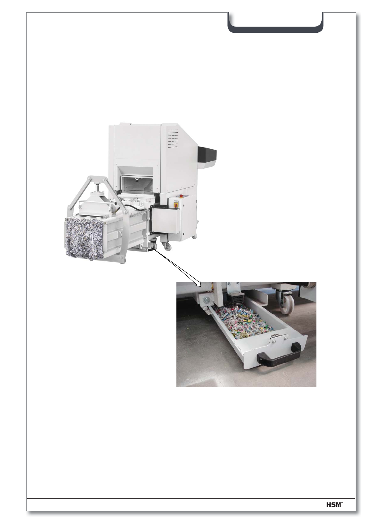
5.2.3 Empty the dust tray
– Switch the main switch off
– Empty the dust tray beneath the baling press once a week
– Be careful to make sure when you slide the the dust tray under the press that the
safety switch snaps in it's position
– Clean the area beneath the baling press -> remove all soil particles!
SP 5088
07/2013 2.991.999.120_en 51
Page 52
SP 5088
5.3 Maintenance of the FA 500.3 shredder
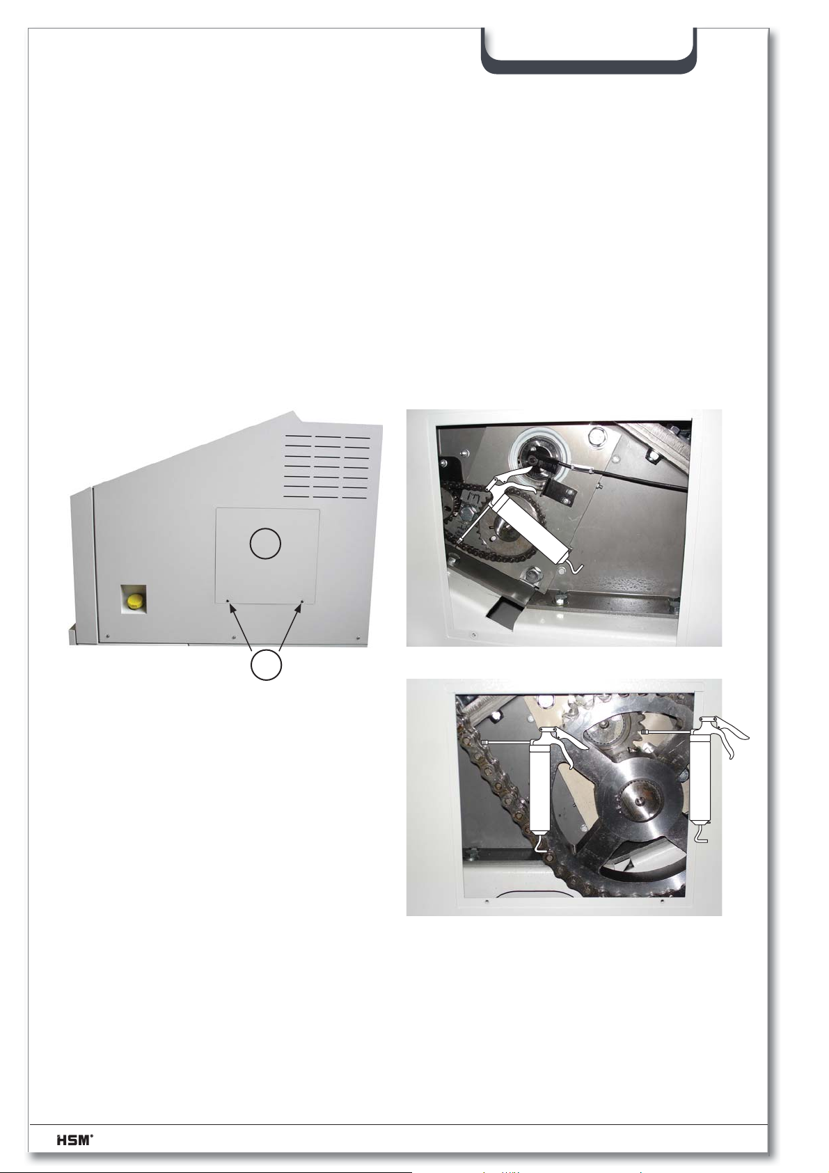
5.3.1 Lubricating the drive chains and synchronized wheels (2 x per year)
- Turn off the main switch and disconnect the red CEE power plug
- Remove the inspection fl aps (1) in the left and right side plates.
Take out the Allen screws (2).
- Lubricate the drive chain of the motor and cutting unit, the drive chain of the
cutting unit and feed belt, and the synchronized wheels.
Recommended lubricant: K2K in accordance with DIN 51502/DIN 51825
1
2
- Mount the inspection fl aps onto the unit again.
52 2.991.999.120_en 07/2013
Page 53
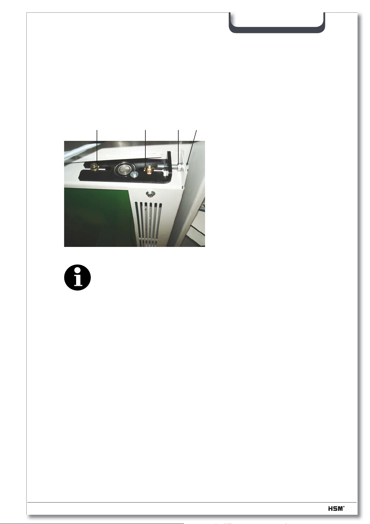
5.3.2 Retighten the feed belt
– Turn off the shredder
– Loosen the hex nuts (3) on the left and right sides of the snub roller.
(Accessible from the below)
– Loosen the lock nuts (4) of the tensioning bolts (5).
– Tighten the feed belt evenly using the tensioning bolts.
SP 5088
3 4
Note
Only tighten the feed belt until it stops slipping. The feed belt bearing
may be damaged if it is tightened too much.
– Tighten the hex nuts on the snub roller and the lock nuts on the tensioning
bolts again.
3
5
5.3.3 Check the directional stability of the feed belt
Switch on the shredder and let it run for approx. 10 minutes.
During this time, the feed belt must run in the middle of the snub roller. If it slips to the left
or right edge, you must alter the setting of the snub roller.
5.3.4 Check the feed belt for wear
The surface of the feed belt can become worn after long periods of use. If you can see
the fabric inlay in the belt, it must be replaced.
Please notify our customer service.
07/2013 2.991.999.120_en 53
Page 54
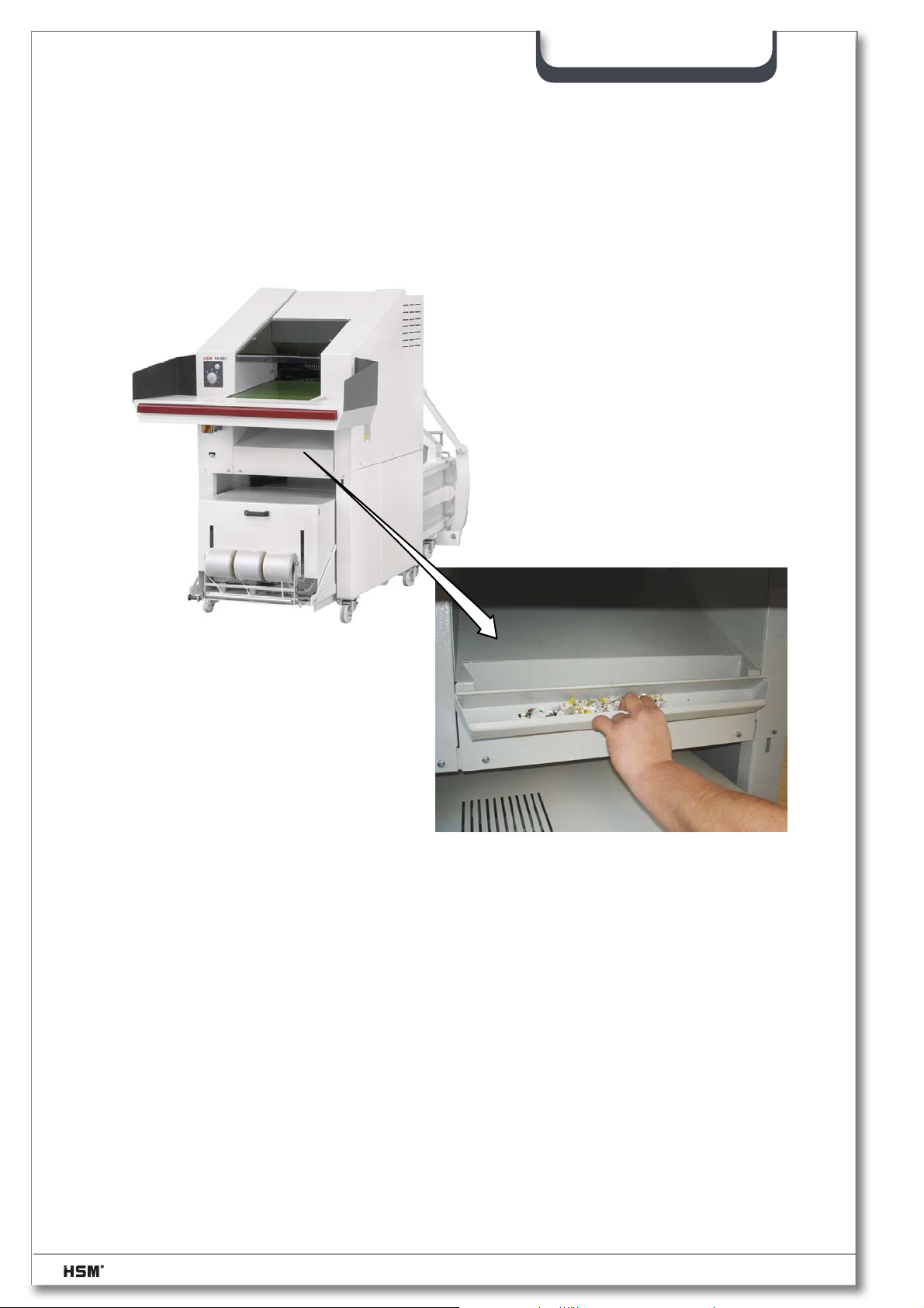
5.3.5 Emptying the collecting tray
– Empty the dirt tray under the feed belt as required
– Clean the area under the Shredder – vacuum the particles of dirt
SP 5088
54 2.991.999.120_en 07/2013
Page 55

6 Storage
If the shredder press combination is to be stored for a lengthy period, make sure that:
• the shredder press combination is disconnected from the power sources
• the shredder press combination is not directly exposed to the weather
• the hydraulic tank, pipes and hoses do not leak
7 Disposal instructions
HSM baling presses / shredders have a long service life. Nevertheless, every machine
reaches a time when inspections and repairs are no longer worth the trouble. The operator
then faces the problem of disposing of the machine properly
We will be glad to advise you about the legal regulations for disposal at the
appropriate time.
SP 5088
The baling press and shredder are made of different materials and need to be disassembled
to separate the materials for recycling. (Ferrous materials, electrical components,
plastics)
The hydraulic tank, pipes and hoses must be drained. It is important to ensure that
leaking or spilled liquids are disposed of using appropriate binding agents or technical
facilities, and do not enter the water, the ground or the sewer system.
In disposing of the respective hydraulic fl uids, the national legal requirements must be
observed.
07/2013 2.991.999.120_en 55
Page 56
7.1 Disposal verifi cation form
To
HSM GmbH + Co. KG
Austraße 1 - 9
D-88699 Frickingen / Germany
The machine specifi ed here
Designation: Baling press / Shredder
Model:
SP 5088
Machine number:
Year of construction:
has been disposed of according the applicable regulations.
Address of the last
operating company
Address of the
waste management company
............................................... ...............................................
Date and signature Date and signature
of the last operator of the disposal company
56 2.991.999.120_en 07/2013
Page 57
8 Using and ordering spare parts
HSM GmbH+Co.KG
Austrasse 1-9
D-88 699 Frickingen
Germany
MODELL
MASCH.-NR.:
SERIEN - NR.:
PRESSKRAFT: kN
zH V :GNUNNAPS
BAUJAHR:
LEISTUNG: kW
NENNSTROM: A
Only use original HSM spare parts!
When ordering spare parts, please always provide:
• the complete machine number
• the year of construction of the baling press
SP 5088
8.1 Customer service address
HSM GmbH + Co.KG
Austraße 1-9
88699 Frickingen, Germany
Tel. +49 7554-2100-300
Fax +49 7554-2100-197
[email protected]
07/2013 2.991.999.120_en 57
Page 58

9 Electrical circuit diagrams
The wiring diagrams are supplied separately with the machine.
(in the control cabinet)
SP 5088
58 2.991.999.120_en 07/2013
Page 59
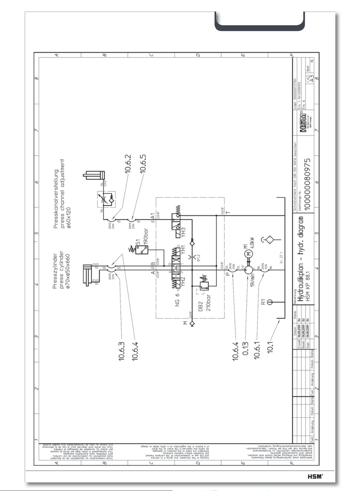
10 KP 88.1 hydraulic diagram
SP 5088
07/2013 2.991.999.120_en 59
Page 60
SP 5088
11 EC declaration of conformity
EC declaration of conformity
The manufacturer HSM GmbH + Co. KG
Austraße 1-9
D - 88699 Frickingen
hereby declares that the described SP 5088 shredder press combination, consisting of the FA
500.3 shredder and the KP 88.1 baling press, comply with the basic safety and health requirements
of the following EC directives:
• 2006/42/EG
• 2004/108/EG
Applied standards and technical specifi cations:
EN1010-3:2002+A1, EN ISO 12100-1:2003+A1:2009, EN ISO 12100-2:2003+A1:2009,
EN ISO 13857:2008, EN 13849-1 (2008), EN 60204-1:2006+A1:2009,
EN 349:1993+A1:2008,EN 55014-1:2006+A1:2009, EN 61000-6-4 (01.07), EN 61000-6-2 (03.06)
The individual operation of the machines is prohibited. Only the combination of the shredder and
the baling press complies with EN 13857 (safety distances).
Salem, 15.02.2011
p. p. Hubert Kötzinger
Head of Environmental Engineering Product Development
Authorised representative for the compilation of technical documentation:
Hubert Kötzinger, HSM GmbH + Co. KG.
The technical documentation in terms of Appendix VII, Part A has been created and is available at
HSM GmbH + Co.KG.
This declaration only relates to those machines that are in the same condition as they were when
put into circulation, no regard can be to parts added later by the end user and/or any work conducted
subsequently.
60 2.991.999.120_en 07/2013
 Loading...