

Page 1
Page 1
HUGO SACHS ELEKTRONIK - HARVARD APPARATUS GmbH D-79232 March-Hugstetten Germany
HSE PLUGSYS® TAM-A Type 705/1 and TAM-D Type 705/2
HSEHSE
for the
PLUGSYS
®
Module
Transducer Amplifier Module TAM
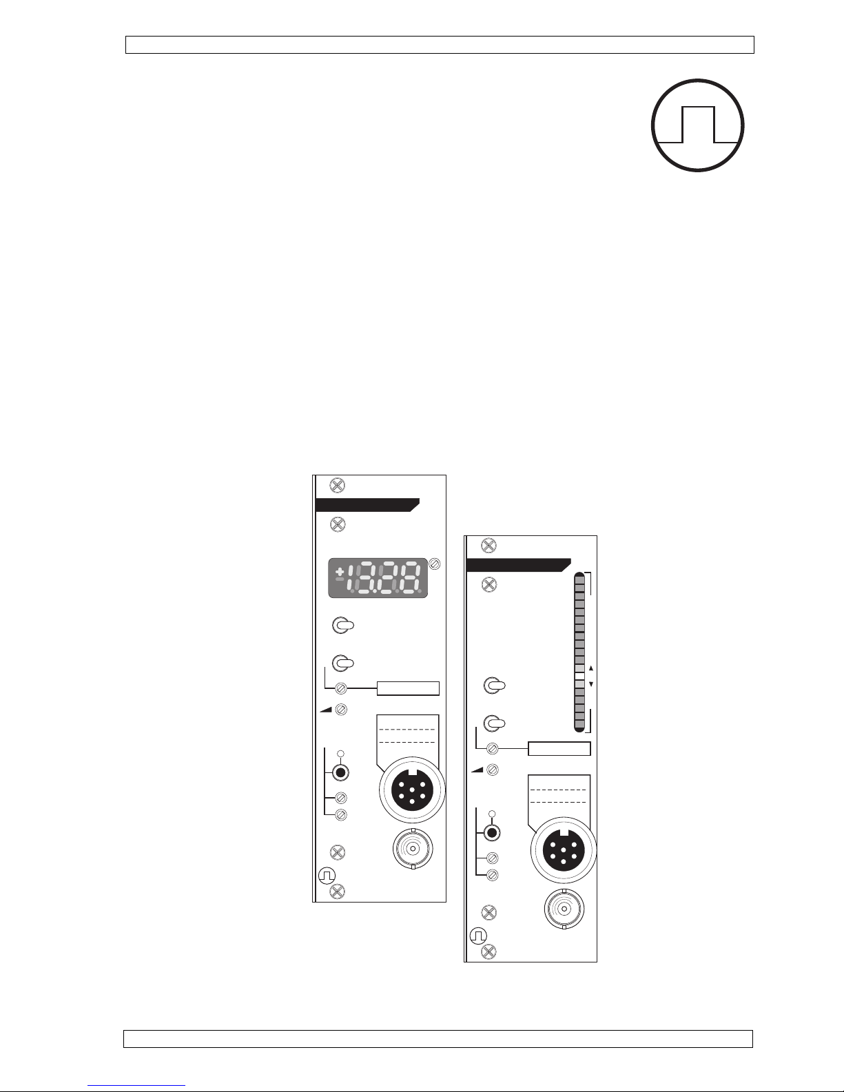
Version TAM-A Type 705/1 with bargraph display
Version TAM-D Type 705/2 with digital display
(Version 1.4 / printet: June 2013 / Hellstab / TB / Zi)
OPERATING INSTRUCTIONS
TAM-D
HUGO SACHS ELEKTRONIK
D-79232 MARCH GERMANY
TRANSDUCER
AMPLIFIER MODULE
CAL MEASURE
OFF
1
300
100 FILTER (Hz)
GAIN
20-100%
OUTPUT
(± 10V)
TYPE 705/2
AUTO
FINE
COARSE
ZERO
REF.
TRANSDUCER
HSE
ADJ.
135
2
4
6
300
135
2
4
6
FILTER (Hz)
TAM-A
HUGO SACHS ELEKTRONIK
D-79232 MARCH GERMANY
TRANSDUCER
AMPLIFIER MODULE
CAL MEASURE
OFF
1
100
GAIN
20-100%
OUTPUT
(± 10V)
TYPE 705/1
AUTO
FINE
COARSE
ZERO
REF.
TRANSDUCER
25
0
25
50
75
HSE
NOT FOR HUMAN USE
Page 2

Page 2
HUGO SACHS ELEKTRONIK - HARVARD APPARATUS GmbH D-79232 March-Hugstetten Germany
HSE PLUGSYS® TAM-A Type 705/1 and TAM-D Type 705/2
Contents
1 Introduction, manufacturer's details .............................................................................................................. 3
1.1 Copyright .................................................................................................................................................. 3
1.2 Trademark ................................................................................................................................................. 3
2 Safety note .................................................................................................................................................. 3
3 General description, application .................................................................................................................. 4
4 Installing the module in a housing ............................................................................................................... 4
4.1 Installation procedure ............................................................................................................................... 4
4.2 Internal settings, jumpers.......................................................................................................................... 5
4.2.1 Protection against electrostatic discharges (ESD) ................................................................................. 5
4.2.2 Location of the jumpers for the internal instrument adjustments ............................................................ 6
4.2.3 Input configuration of the amplifier (jumper J7) ...................................................................................... 7
4.2.4 Amplification GAIN (jumper J2) ............................................................................................................... 7
4.2.5 Autozero coupling (jumper J8) ................................................................................................................ 9
4.2.6 Filter setting mean output MEAN (jumper J3) ......................................................................................... 9
4.2.7 BNC socket Puls. or mean output (jumper J4) ........................................................................................ 9
4.2.8 Internal signal outputs PULSE and MEAN (jumper J5) ........................................................................... 9
4.2.9 Setting of the decimal point TAM-D (jumper J1) ..................................................................................... 10
4.2.10 Mean value filter digital display TAM-D (jumper J6) ..............................................................................10
4.3 Signal input ..............................................................................................................................................10
5. Controls TAM-A........................................................................................................................................ 11
5.1 Controls TAM-D ........................................................................................................................................ 12
6. Start-up .................................................................................................................................................... 13
6.1 Transducer calibration ..............................................................................................................................13
6.1.1 Basic setting for transducer calibration .................................................................................................. 13
6.1.2 Transducer calibration TAM-A ................................................................................................................ 14
6.1.3 Transducer calibration TAM-D with a digital voltmeter or a DAQ system ................................................15
6.1.4 Transducer calibration on a TAM-D with using the digital display (procedure for users who
don´t have a digital voltmetern nor a DAQ system ..................................................................................16
7. Zero compensation ZERO ......................................................................................................................... 17
7.1 Manual zero adjustment ...........................................................................................................................17
7.2 Automatic zero adjustment....................................................................................................................... 17
8. Filter 30 - 100 - 300 Hz .............................................................................................................................. 18
9. Maintenance notes.....................................................................................................................................18
9.2 Technical data TAM .................................................................................................................................. 19
Index ...............................................................................................................................................................20
Reply Form ........................ ..........................................................................................................................21
Application notes ..........................................................................................................................................22
Page 3

Page 3
HUGO SACHS ELEKTRONIK - HARVARD APPARATUS GmbH D-79232 March-Hugstetten Germany
HSE PLUGSYS® TAM-A Type 705/1 and TAM-D Type 705/2
March-Hugstetten, June 2008
1 Introduction, manufacturer's details
1.1 Copyright
This product and the corresponding documentation are protected by copyright. All rights reserved. This document must not be copied, photocopied, reproduced or translated, either as a whole or in parts, without prior
written agreement by HUGO SACHS ELEKTRONIK - HARVARD APPARATUS GmbH, March/Hugstetten, Germany.
PLUGSYS® is a registered trademark of HUGO SACHS ELEKTRONIK - HARVARD APPARATUS GmbH,
March-Hugstetten. Other trademarks shown in the Operating Instructions are the property of the corresponding applicant.
2 Safety note
the equipment is designed for use in general laboratories, light industrial and office environments.
Operation in hazardous areas and/or in a flammable atmosphere is not permitted.
1.2 Trademark
Warning:
All the information in these Instructions has been drawn up after careful examination but does not
represent a warranty of product properties. Alterations in line with technical progress are reserved.
These Operating Instructions describe the function and use of the TAM-A Module Type 705/1 and the TAM-D
Module Type 705/2. They are part of the plug-in module and have to be kept close to it. The information provided
on the TAM has to be read in conjunction with the remaining system documentation of the PLUGSYS housing.
This PLUGSYS module is manufactured by
HUGO SACHS ELEKTRONIK HARVARD APPARATUS GmbH
Gruenstrasse 1,
79232 March-Hugstetten
Phone (Germany) :
Phone (others) :
Fax (Germany) :
Fax (others) :
eMail:
07665-9200-0
(int + 49) 7665-9200-0
07665-9200-90
(int + 49) 7665-9200-90
Page 4

Page 4
HUGO SACHS ELEKTRONIK - HARVARD APPARATUS GmbH D-79232 March-Hugstetten Germany
HSE PLUGSYS® TAM-A Type 705/1 and TAM-D Type 705/2
3 General description, application
The transducer amplifier module TAM is equipped, depending on the version, either with analogue
(TAM-A) or digital (TAM-D) display. Apart from a few exceptions, the amplifiers of the
two versions are identical. In the description below, the symbol TAM refers to both
module versions. The symbol TAM-A or TAM-D is used when referring to the different
properties of the two amplifier variants.
The amplifier module TAM is a univeral DC bridge amplifier. In conjunction with a suitable resistive transducer
it permits direct measurement of e.g. force, pressure or displacement. The amplifier is arranged as a plug-in
module of the PLUGSYS measuring system and is operated inside a PLUGSYS housing.
TAM-A (Type 705/1) is equipped with a LED line, a so-called bargraph. Visual analogue presentation of the
measured signal, is ideally suitable for monitoring dynamic signals.
TAM-D (Type 705/2) carries a 3½-digit LED display. It is therefore particularly suitable for evaluating static
signals. The instantaneous measurement can be read directly on the numerical display of the TAM-D. By
calibrating the module to the transducer it is possible to adjust the sensitivity of the display so that the measurement can be read off directly (e.g. force in ±100 mN, pressure in ±200 mm Hg, displacement in ±4 mm etc.).
The amplification (Gain) of the TAM can be adjusted over a very wide range (x2 to x10 000) to suit the requirements of the transducer. The DC supply (excitation voltage) for the transducer is fixed at 5 V, the value commonly employed today.
As a special feature, both amplifiers TAM-A and TAM-B are equipped with automatic zeroing in addition to
manual zero adjustment.
In order to have an easy calibration of a connected data acqusistion system a predefinded value eg. 10mN,
100mmHg or 5mm can be simulated on the output.
The output filter 30-100-300 Hz is used for smoothing the signal. It acts on both signal
outputs PULSE (internal) and BNC socket (front panel). The internal signal output MEAN is preceded by a lowpass filter of 0.1 or 0.3 Hz. As an option the MEAN output can be connected to the BNC socket on the front panel
through an internal jumper on the circuit board.
4 Installing the module in a housing
The TAM module is designed as a PLUGSYS module and has a width of 8E corresponding to two slots. It can
be installed directly in any housing with a system bus. An exception is the PLUGSYS MiniCase Type 609; the
TAM can also be operated in this housing but installation requires some soldered connections and it is therefore only supplied completely installed from the factory.
If you bought your module installed in a housing these adjustments already have been made in the factory
prior to shipping.
Switch off the housing and pull out the mains plug.R
Remove the blank panel at the housing slot position intended for the TAM module.R
Make the internal adjustments according to Section 4.2.R
Insert the TAM module, note the guide rails.
R
Firmly push in the module, it must clearly engage with the bus connector.
R
Screw on the front panel, reconnect the mains cable to the housing, and plug in the transducer.
R
Before the module is installed in a housing it is necessary to make a number of internal adjustments. First it is
necessary to carry out the adjustments described in Section 4.2. Note the precautions described in Section
4.2.1 which are absolutely essential in order to avoid electrostatic discharges.
Brief procedure (for full details see the Operating Manual of the housing):
4.1 Installation procedure
Page 5

Page 5
HUGO SACHS ELEKTRONIK - HARVARD APPARATUS GmbH D-79232 March-Hugstetten Germany
HSE PLUGSYS® TAM-A Type 705/1 and TAM-D Type 705/2
4.2.1 Protection against electrostatic discharges (ESD)
Equilibrate potentials by touching earthed metal objects, e.g. housing of some electrical equipment
connected to the supply, central heating radiator etc.
R
In order to avoid fresh electrostatic charges, do not move unnecessarily backwards and forwards on
your working area. Where available, it is best to wear an antistatic wristband for continuous discharge of
static electricity.
R
When you remove the TAM from its antistatic packaging, touch first the front panel of the module to
equilibrate the potentials.
R
For the internal adjustments place the module flat on the foil of the antistatic packaging.R
Take care in handling the amplifier module, avoid bending the circuit board and unnecessary touching of
its components.
R
Before inserting the module in the housing, ensure potential equilibration between the module, yourself
and the housing. First touch the metal housing before inserting the TAM.
R
When handling the module during use it is equally important to ensure that no electrostatic discharges
take place through the inner pins of the input or output sockets. For this reason you should always first
provide potential equilibration between yourself, the PLUGSYS and the transducer or recording system.
4.2 Internal settings, jumpers
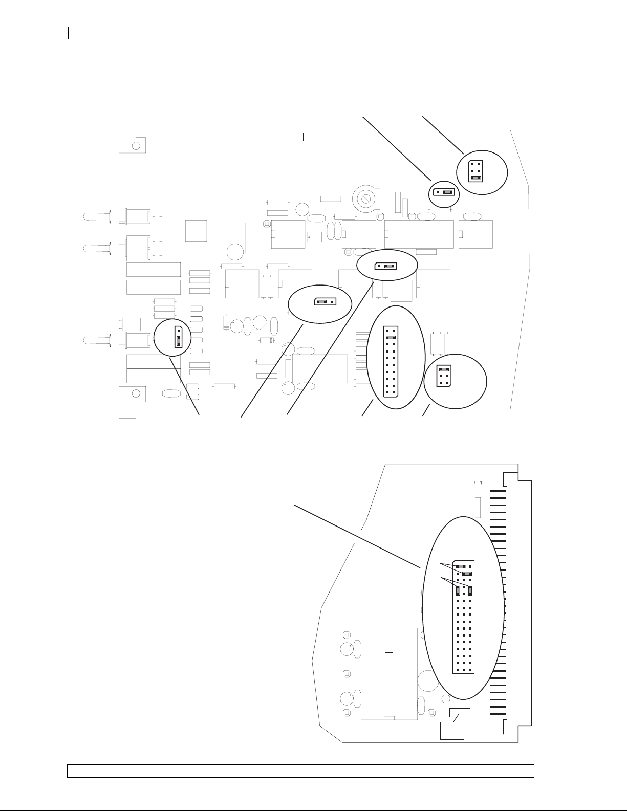
In order to adjust the TAM to the individual application the following settings have to be made with jumpers on
the module circuit board. See diagrams next page !
R
R
R
Jumper J1 (TAM-D only): position of decimal point on the digital display
Jumper J2: gain of the input amplifier GAIN x1 - x1000 (the overall gain is 10x higher due to the subse-
quent output amplifier)
Jumper J3: time constant for the MEAN output 0.1 or 0.3 Hz
R
Jumper J4: PULSE or MEAN output at the BNC socket on the front panel
R
Jumper J5: bus lines AV1 - 16 for the internal signal outputs PULSE and MEAN
R
Jumper J6: (TAM-D only) input filter of digital display SLOW - FAST
R
Jumper J7: input selection between transducer with resistance bridge circuit (POS.2) or voltage input
from transducer with integrated amplifier (POS.1)
R
Jumper J8: to adjust the calibration range of the autozero to the selected amplification and the internal
resistance of the transducer.
Modern electronic components are very sensitive to electrostatic discharges. Even the smallest electrostatic
charge may damage the electronics or lead to faults. Therefore follow the steps described below in order to
discharge any possible static electricity on your body.
Tip
Page 6
Page 6
HUGO SACHS ELEKTRONIK - HARVARD APPARATUS GmbH D-79232 March-Hugstetten Germany
HSE PLUGSYS® TAM-A Type 705/1 and TAM-D Type 705/2
4.2.2 Location of the jumpers for the internal instrument adjustments
fuse
1A/SF
1
32
DGND
-15V
AGND
+15V
TEM 3-0522
+5V
(+5V)
(DGND)
PULSE
AV 1-16
MEAN
10
11
12
13
14
15
16
A
B
1
2
3
4
5
6
7
8
9
FILE: TAM_DP1.FH3
J7
DP 705-1/b
J4 J3 J2 J8
J6
J1
x1000
x500
x200
x100
x50
x20
x10
x5
x2
x1
GAIN
DP-2
DP-3
DP-4
J1
SLOW - FAST
J6
POS.1
POS.2
0.1Hz
0.3Hz
Filter MEAN
PULSATILE
MEAN
OUTPUT
(front panel)
A (low)
B (mean)
C (high)
RANGE of AUTO ZERO
J5
In the circle asside you see 3 coulums of pins.
On all left pins the pulsatile signal is available
The center pins are connected to the bus lines AV1 ...
AV16
On all right pins you have the filtered mean signal
avaialable.
T o connect e.g. the pulsatile pressure signal to signal
line AV1 set the jumper as described in A (upper left
jumper).
In this example the second jumper connects the
MEAN signal to analog line AV2
B shows the jumpers in park position if the rear
analog output is not used.
Page 7

Page 7
HUGO SACHS ELEKTRONIK - HARVARD APPARATUS GmbH D-79232 March-Hugstetten Germany
HSE PLUGSYS® TAM-A Type 705/1 and TAM-D Type 705/2
4.2.3 Input configuration of the amplifier (jumper J7)
As a first step the operating mode of the input amplifier has to be selected to suit the type of transducer.
The most widely used transducers are based on a resistance bridge circuit (Wheatstone bridge) with an internal resistance in the range 100 - 1000 Ohm. The input amplifier has to be switched to push-pull input (differential amplifier), Jumper J7 on POS.2.
R2
R4
R3
R1
excitation voltage (+)
signal (+)
excitation voltage (-)
signal (-)
case, shield
Typical arrangement of a transducer with bridge circuit
Less widely used are transducers with built-in preamplifier. Depending on type, the measurement signal is
amplified by these active transducers up to the Volt range. The input amplifier of the TAM is switched as
straight amplifier, Jumper J7 on POS.1
case, shield
Transducer
+
Amp.
Output
Power (+)
Power (-)
Sig. GND
Typical arrangement of a transducer with preamplifier
In order to avoid damage to the electronics of the transducer, check first that a supply voltage of
5 Volt (50 mA) can be used as bridge supply. Special attention must be paid to correct polarity.
4.2.4 Amplification GAIN (jumper J2)
The amplification of the TAM can be adjusted over a very wide range (x2 - x10 000) to suit the requirements of
the transducer. The amplification to be set depends essentially on the sensitivity of the transducer (amplitude
of the measurement signal) and on the required measuring range.
The selected gain of the preamplifier x1 / x2 / x5 / x10 / x20 / x50 / x100 / x200 / x500 / x1000 is
multiplied by 10 due to the additional fixed gain of 10 of the output amplifier.
Note
Warning
Page 8
Page 8
HUGO SACHS ELEKTRONIK - HARVARD APPARATUS GmbH D-79232 March-Hugstetten Germany
HSE PLUGSYS® TAM-A Type 705/1 and TAM-D Type 705/2
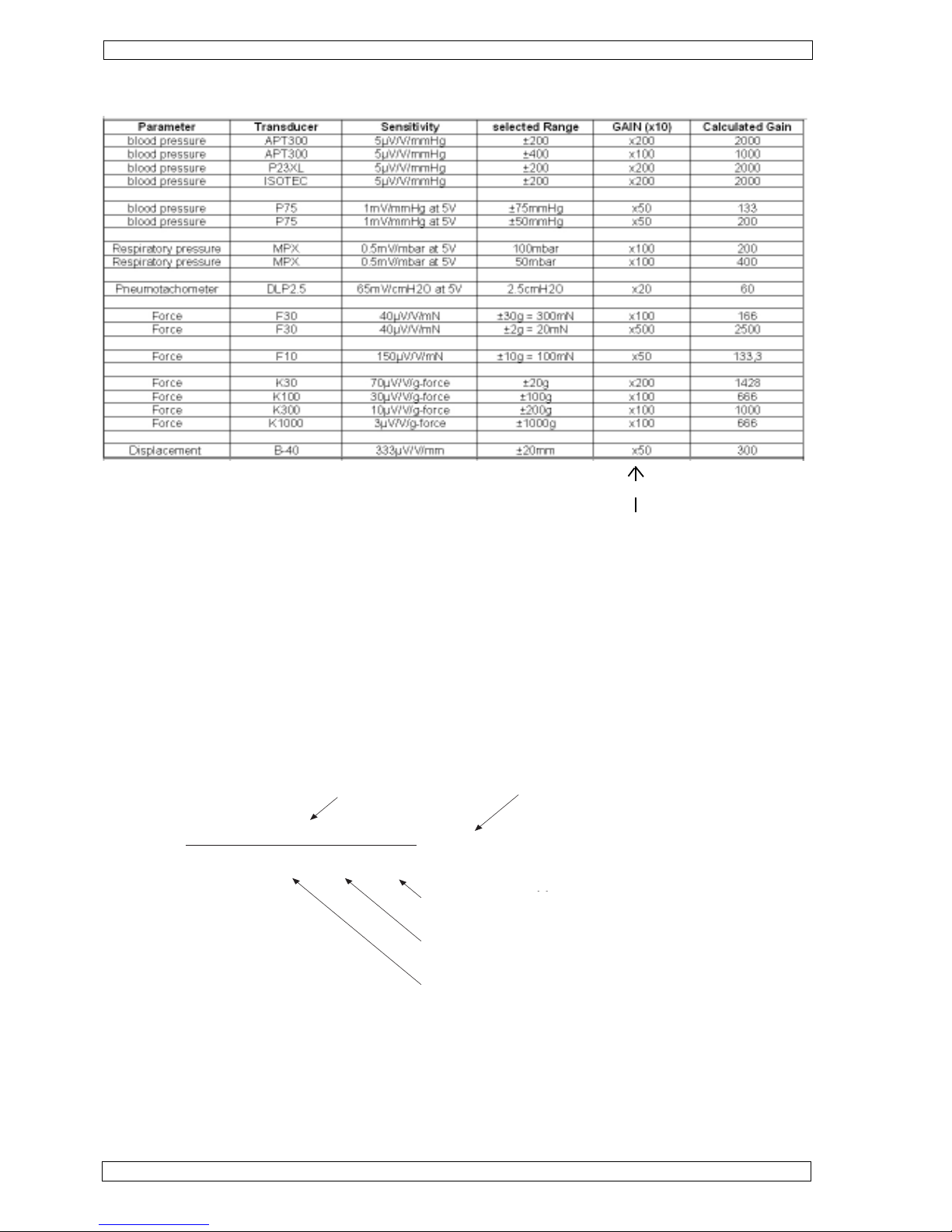
With a known transducer sensitivity (e.g. Isotec transducer 5.05 µV / Volt supply / mm Hg)
the gain is calculated as follows:
Range ±200 mmHg (can be selected individually)Details:
Bridge supply voltage 5 Volt (fixed)
Output voltage range of TAM ±10 V (fixed)
Transducer sensitivity 5.05 µV / Volt supply / mm Hg (see transducer data sheet)
As the GAIN fine trimmer does only allow gain reduction, the gain jumper should allways be set to the next higher
possible value. In the example above the gain should be set to 200. This gives an overall amplification of 200
(preamplifier) times 10 (output amplifier), equal to 2000x. The exact adjustment of the gain to 1980 is made
through the transducer calibration on the front trimmer "GAIN 20-100%".
10
((5.05 x 10
-6
) x 5 x 200)
= 1980.2
output voltage in volt
gain required
range on mm Hg
bridge suply voltage
transducer sensitivity
e.g. 5.05 µV/V/mm Hg
range in mm Hg
The table below provides information on typical amplifier adjustments for standard transducers and applications.
Set GAIN on board with Jumper J2
Page 9

Page 9
HUGO SACHS ELEKTRONIK - HARVARD APPARATUS GmbH D-79232 March-Hugstetten Germany
HSE PLUGSYS® TAM-A Type 705/1 and TAM-D Type 705/2
4.2.5 Autozero coupling (jumper J8).
Automatic zeroing (autozero) operates digitally with a resolution of 12 bit. This represents an adjustment range
of 4096 steps (±2048 steps). Zero adjustment operates directly on the amplifier input so that the zero shift per
step depends on the internal resistance of the transducer and on the gain setting. As a basic setting the jumper
J8 has to be placed in position (B) (medium).
In case zeroing presents low accuracy (large zero shift per step), at a very large gain setting or at a high
transducer resistance (internal resistance greater than 1 kOhm) the position A (low) should be selected. This
reduces the effectiveness of the autozero function, there is a smaller zero shift per step.
By contrast it is possible with low gain and low transducer resistance (internal resistance 100 - 500 Ohm) that
the autozero adjustment range is not sufficient. The autozero effect must then be increased, jumper in position
C (high). This results in a larger zero shift per step and therefore also a larger autozero adjustment range.
Jumper J4 assigns to the monitoring output on the front (BNC socket) either the pulsatile
or the mean value output. In order to see the real unfiltered signal, normally the pulsatile output
should be selected. On the TAM-A the measured signal then corresponds to the signal
course on the bargraph.
When using the mean value output at the BNC socket the output signal is no longer identical with
the phasic wafeform of the measured signal. This may erroneously be considered
as a fault on the output.
4.2.7 BNC socket Pulsatile or Mean output (jumper J4)
Warning
4.2.8 Internal signal outputs PULSE and MEAN (jumper J5)
The internal signal outputs PULSE and MEAN of the TAM are each assigned by a jumper on the link connector
J5 to an analogue bus line (AV1 - AV16).
Be sure to select an AV bus line which is not in use and is therefore free. Duplicate connection
causes short-circuiting of the two signal outputs. Details of the AV lines already being used in the
system can be taken from the bus diagram of the PLUGSYS housing. See chapter 1
of the white operating instructions folder (delivered with each housing).
If there is no bus diagram it is unfortunately necessary that the settings on your
system are determined again. For that purpose all the modules have to be removed
in turn and the AV circuit arrangement set on them has to be checked and written down.
Warning
The diagram in Section 4.2.2 illustrates at (A) the assignment of the PULSE output to AV-1 and that of the
MEAN output to AV-2. It is not essential to use both signal outputs, and the jumpers can then be stored safely
on the outer pin rows as shown at (B) (parking position). In this position the jumper is ineffective.
The AV setting which you have made on the TAM must be documented in the bus
diagram of the housing.
Important
4.2.6 Low pass filter setting mean output MEAN (jumper J3)
The time constant (filter action) of the MEAN signal output of the TAM can be set to 0.1 or 0.3 Hz. 0.1 Hz should
be selected as the basic setting. This provides maximum smoothing of the pulsatile signal (e.g. blood pressure
trace). The mean value (mean pressure) can then be obtained at the MEAN signal output. In view of the large
time constant of 10 seconds in position 0.1 Hz, signal changes at the MEAN output can only be measured
correctly if the measurement signal changes take place more slowly than 0.1 Hz. Otherwise part of the averaged
signal is suppressed in addition to the pulsatile signal. In that case the mean value filter must be set to 0.3 Hz
(3.3 seconds).
Page 10

Page 10
HUGO SACHS ELEKTRONIK - HARVARD APPARATUS GmbH D-79232 March-Hugstetten Germany
HSE PLUGSYS® TAM-A Type 705/1 and TAM-D Type 705/2
4.2.9 Setting of the decimal point TAM-D (jumper J1)
4.2.10 Mean value filter for digital display TAM-D (jumper J6)
The digital display on TAM-D is preceded by the selectable signal filter. In its normal setting "FAST" (1.6 Hz)
the display directly follows the input signal according to the measuring sequence. In the "SLOW" setting (0.15
Hz) there is a pronounced averaging effect. The settling time of the filter is then approx. 6 seconds.
DP-2
DP-3
DP-4
On TAM-D the decimal point position in the digital display can be freely selected. The
indicated value then corresponds exactly of the measuring range which you require. For
example, for the range ±10.00 mN the jumper should be set to position DP-3. In case no
decimal point is required remove the jumper and set it to one pin. For measuring blood
pressures up to 200mmHg you have to remove this jumper, so that no decimal point is
displayed.
4.3 Signal input
The signal input is a 6-pin Binder or Amphenol-Tuchel fitted socket with screw lock.
Suitable plugs:
Binder Type: 09-0321-00-06
Amphenol Type: T3400501
Pin connections:
Pin 1 (+) supply +5 Volt (50 mA)
Pin 2 (-) signal input
Pin 3 midpoint of the optional internal half-bridge (+2.5 Volt)
Pin 4 (+) signal input
Pin 5 (-) supply (circuit null)
Pin 6 not used
The connector housing must be connected to the shield screen in the cable
and the transducer housing (it must not be connected to the circuit null pin
5). Use only shielded cables !
135
2
4
6
Page 11
Page 11
HUGO SACHS ELEKTRONIK - HARVARD APPARATUS GmbH D-79232 March-Hugstetten Germany
HSE PLUGSYS® TAM-A Type 705/1 and TAM-D Type 705/2
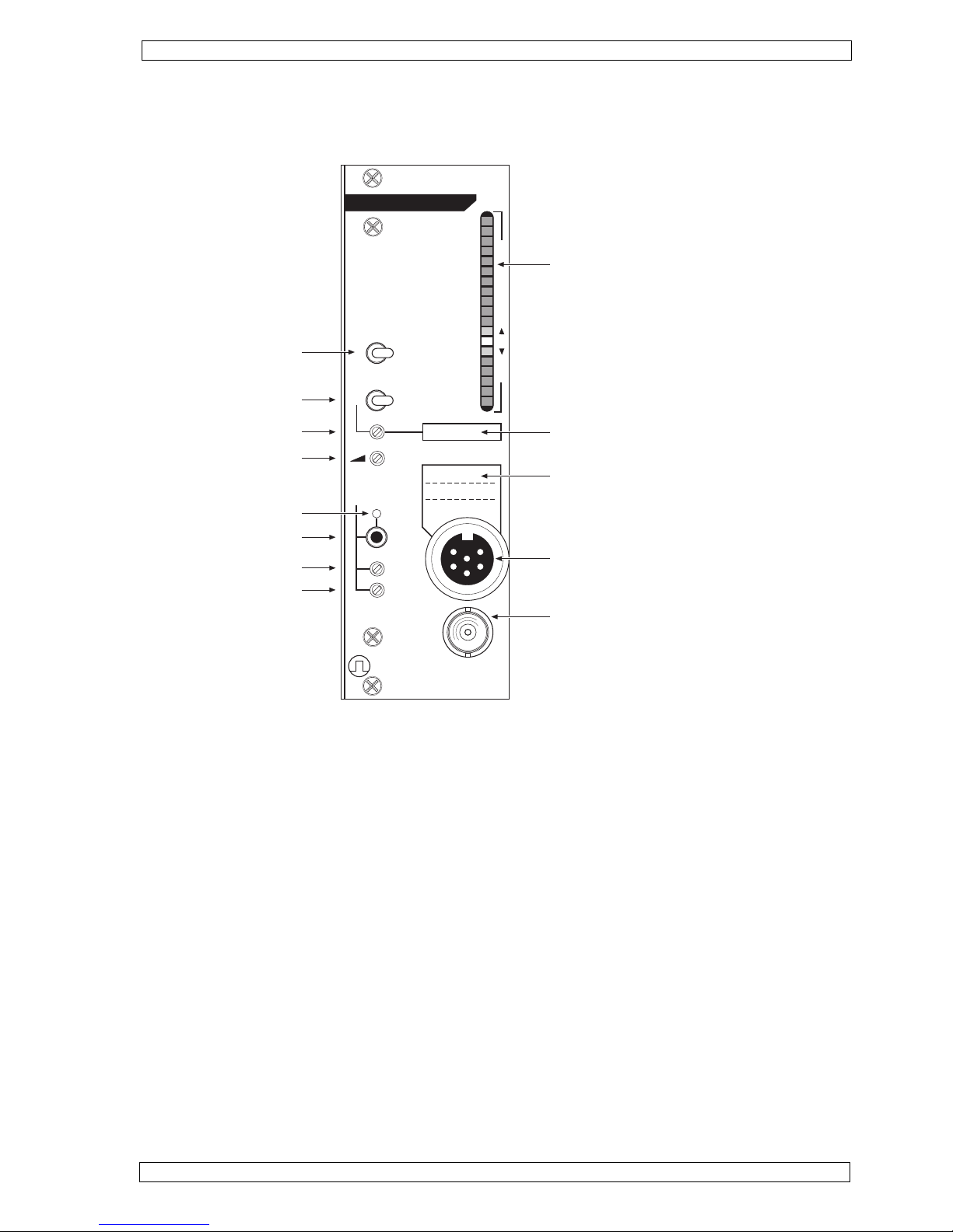
5. Controls TAM-A
TAM-A
HUGO SACHS ELEKTRONIK
D-79232 MARCH GERMANY
TRANSDUCER
AMPLIFIER MODULE
CAL MEASURE
OFF
1
300
100
GAIN
20-100%
OUTPUT
(± 10V)
TYPE 705/1
AUTO
FINE
COARSE
ZERO
REF.
TRANSDUCER
25
0
25
50
75
HSE
135
2
4
6
FILTER (Hz)
LED bargraph
Marker field for reference, e.g.
10 mN
Marker field for calibrated transducer,
e.g. Type F30 No. 1
Signal input
Output (PULSE or MEAN)
Filter settings
Operating mode
CAL setting
Amplification setting
Autozero status LED
Autozero key
Manual zero fine
Manual zero coarse
100 % equal to 10V output voltage
low pass filter
socket
Page 12
Page 12
HUGO SACHS ELEKTRONIK - HARVARD APPARATUS GmbH D-79232 March-Hugstetten Germany
HSE PLUGSYS® TAM-A Type 705/1 and TAM-D Type 705/2
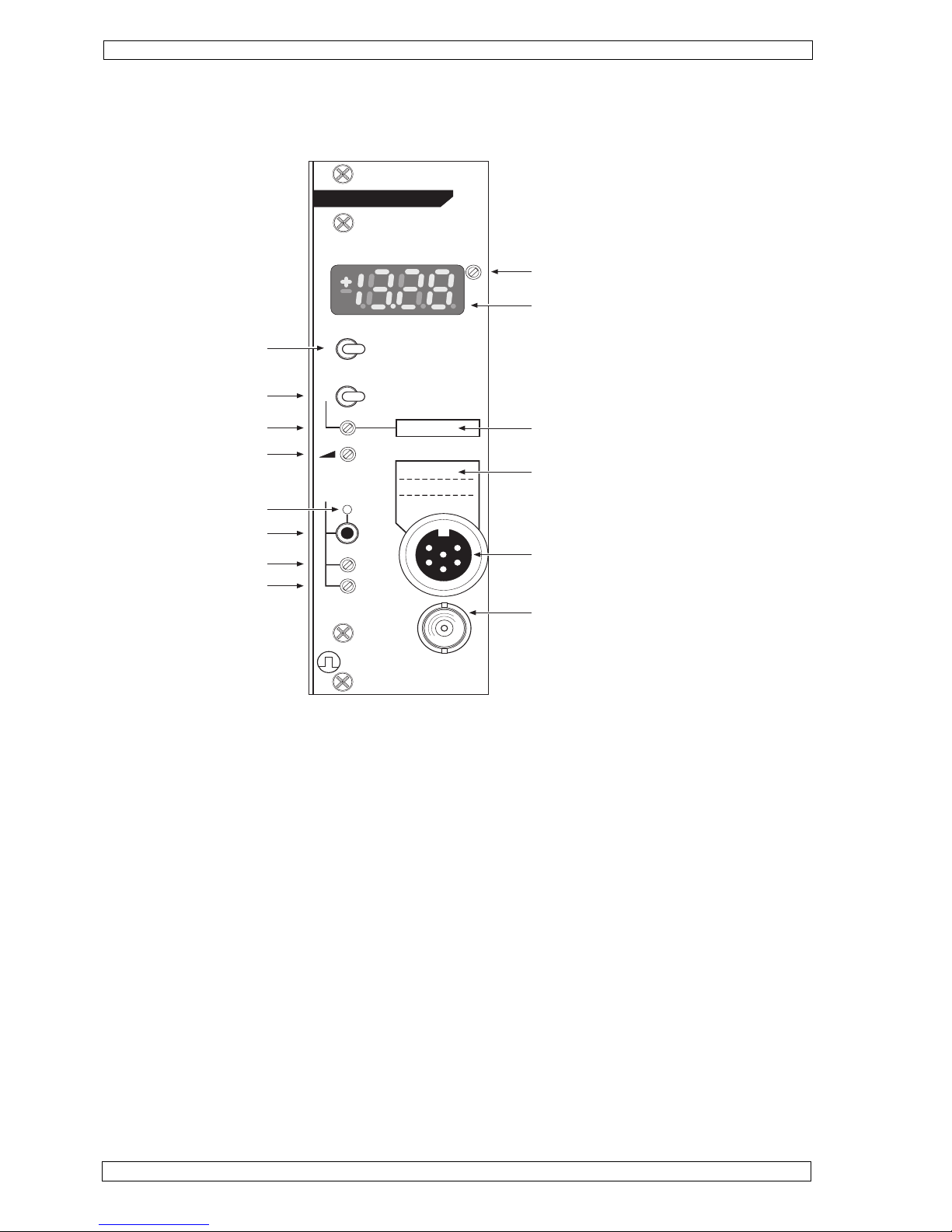
5.1 Controls TAM-D
HSE
TAM-D
HUGO SACHS ELEKTRONIK
D-79232 MARCH GERMANY
TRANSDUCER
AMPLIFIER MODULE
CAL MEASURE
OFF
1
300
100 FILTER (Hz)
GAIN
20-100%
OUTPUT
(± 10V)
TYPE 705/2
AUTO
FINE
COARSE
ZERO
REF.
TRANSDUCER
ADJ.
1
3
5
2
4
6
Marker field for calibrated transducer,
e.g. Type F30 No. 1
Signal input
Output (PULSE or MEAN)
Filter setting
Operating mode
CAL setting
Amplification setting
Autozero status LED
Autozero key
Manual zero fine
Manual zero coarse
LED digital display
Display range adjustment
Marker field for reference,
e.g. 10 mN
Page 13

Page 13
HUGO SACHS ELEKTRONIK - HARVARD APPARATUS GmbH D-79232 March-Hugstetten Germany
HSE PLUGSYS® TAM-A Type 705/1 and TAM-D Type 705/2
6. Start-up
After you have completed the module installation, connected the transducer to the TAM, switch on the power on
the housing. The first step is to calibrate the TAM to the transducer. This may involve adjusting the gain of the
TAM to suit the transducer sensitivity and the required range. In addition the CAL Value (simulated static value
e.g,. 100mmHg) for calibrating the recording system has to be set.
.
6.1 Transducer calibration
The following points have to be considered first:
R
Establish the required measuring range, e.g. ±200 mmHg. Note that the maximum
expected signal has to be smaller than the selected range. Do not oversee the pulsatile part of the signal
(e.g. the systolic diastolic pulsation of blood pressure). Also have in mind that testing a drug may increase
dramaticaly the signal amplitue. Note, that the selected range should be 10 -20 % higher than the maximum expected signal.
R
Output voltage corresponding to the selected range (i.e. to ±200 mmHg).
Important
The signal voltage span of the PLUGSYS measuring system is fixed at ±10 Volt. The goal
should always be to produce maximum amplifier output to have the best ratio between useful
signal and resolution. It means that under ideal conditions the range corresponds to the
output voltage of ±10 Volt. On TAM-A there is a further advantage through the better deflection of the bar graph indication. The dynamic (pulsatile part) of the measured signal is much
better seen.
R
Determine the calibration signal, e.g. 100mmHg, for calibrating the recording system to
which TAM is connected. By switching the operating mode from MEASURE to OFF and
then to CAL it is possible to simulate a static value of e.g. 100 mmHg.
6.1.1 Basic settings for transducer calibration
R
Set output filter to 300 Hz
R
Set operating mode to MEASURE
R
Set GAIN 20-100% to 100%, fully clockwise (clicking noises) on the multi-turn trimmer
R
Set fine manual zero adjustment to mid-position (19 turns anticlockwise and then 9 turns clockwise)
Initialize the autozero function to the mid of the calibration range. To do so start the autozero function with
the transducer disconnected. Since no transducer is connected to the TAM, zeroing is not possible and
the function is aborted with an error message. In that case the autozero function is normalised to its mid
setting. This procedure is essential to ensure that during later operation the autozero function has maximum action in both positive and negative direction. After this adjustment, connect the transducer back to
the TAM.
R
Since the zero of most transducers is affected by its position, the transducer should during calibration be
secured on the bench in its operating position, e.g. by a stand, clamp or some suitable component.
R
On the TAM-D the adjustment ADJ. next to the digital display, a multi-turn trimmer, must be turned fully
clockwise (clicking noises). The indicated value, referred to the output voltage, corresponds to 10 Volt =
1000 or 100% of the maximum possible range. The position of the decimal point is disregarded.
R
See also the description of the autozero function below (Section 7.2).
It is essential that the housing of the input plug is screwed to the socket on the front panel.
This is necessary to ensure a secure connection between cable screen and transducer
housing screen. Protection against electrostatic discharges is ensured only when the plug
case has been properly screwed to the socket.
Important
If you bought the transducer together with the TAM amplifier module these settings already have been
done in the factory. See handwritten texts on TAM frontpanel.
Furthermore it is assumed that the internal GAIN jumper already has been set according chapter 4.2.4
Page 14

Page 14
HUGO SACHS ELEKTRONIK - HARVARD APPARATUS GmbH D-79232 March-Hugstetten Germany
HSE PLUGSYS® TAM-A Type 705/1 and TAM-D Type 705/2
6.1.2 Transducer calibration TAM-A
R
The bargraph has one fix LED on position Zero, which is always on. A second LED may be on, anywhere
on the bargraph when there is no load on the transducer. Carry out an approximate zero adjustment
manually with the adjustments ZERO-COARSE first and then ZERO-FINE so both LED's overlap. If a
voltmeter is connected at the BNC output it should show as good as possible 0 Volt
R
Start the AUTOZERO function by pressing the AUTO button in MEASURE MODE until the LED ZERO
goes on, for precise zeroing. The LED ZERO must automatically go off after a few seconds and not be
flashing at the end of the adjustment (no error, zero adjustment OK!).
R
Using a pressure calibrator, apply the calibration reference e.g. 100mmHg to the transducer without altering the position of the transducer (zero error).
In the case of the example, the output voltage of ±10 Volt is equivalent to a measurement range of
±200mmHg.
Now take the litle red screwdriver which was delivered with the system and adjust on the
GAIN 20-100% trimmer the gain so that you get e.g. 5V (50% bargraph deflection)
which is equal to 5V on the output. The adjustment should be made in conjunction with
the recording device (recorder, data acquisition system, oscilloscope) or a commercial
voltmeter.
The larger the applied calibration reference, the more accurate the adjustment can be made. The ideal situation is when the applied reference equals the measuring
range.
Tip
R
The final step should be to check the zero again. The calibration reference load on the transducer is removed. The signal output of the TAM must then again be exactly zero. If this is not
the case, it is probable that application of the calibration reference load has shifted the transducer zero. A possible cause is a change in the position of the transducer, pulling on the
connecting cable etc. In order to achieve maximum accuracy it is necessary to repeat the
above adjustment procedure.
Important
The last step is to set the CAL value which can simulate a preset value on the TAM output. Set switch
CAL-OFF-MEASURE to CAL position. A freely set static calibration value e.g. 100mmHg can at any time
be simulated on the signal output of the TAM.
R
Method 1: Adjustment using the recording device
With the TAM in MEASURE mode apply to the transducer, using the calibrator, the reference value you
want to simulate. Check for the reading of your recording device. On the TAM, switch now to operating
mode CAL. Turn on the CAL adjustment trimmer so that your recording device shows the same reading as
with the calibration reference before.
Easiest calibration can be made with connecting a digital voltmeter to the BNC output on the frontpanel.
Brief description in short form (example with a pressure transducer):
Wished range 200mmHg: which means 200mmHg should be equal to 10V at the BNC output.
Adjust Zero with transducer open to air, connect pressure calibrator and attach 100mmHg,
set GAIN so that you get 5V on the analog output.
Detailed description:
/
Sorry
In case the amplifier deflection is smaller than expected, the internal gain has
to be suitably increased. The procedure for transducer calibration as described
so far must then be repeated.
Page 15

Page 15
HUGO SACHS ELEKTRONIK - HARVARD APPARATUS GmbH D-79232 March-Hugstetten Germany
HSE PLUGSYS® TAM-A Type 705/1 and TAM-D Type 705/2
This method is possible only when the transducer calibration has been made as an exact
voltage of e.g. 5V/100mmHg. Bring the TAM module in operating mode CAL and connect
a voltmeter to the BNC signal output. Using the CAL adjustment the output voltage is now adjusted to 5
Volt. The output voltage in the CAL position then corresponds to the required CAL value of e.g. 100
mmHg.
Method 2: Adjustment using a voltmeter on the BNC output
In order to remind the simulated calibration value e.g. 100mmHg please write the value with a soft pencil
on the appropriate marker fields on the front panel of the TAM. Any existing writing can readily be removed
using a soft rubber.
R
6.1.3 Transducer calibration on a TAM-D with a digital voltmeter or a DAQ system
The transducer calibration on the TAM-D follows essentially the same procedure as that of
TAM-A. Here additionally the value you measure is displayed as a number in units (e.g. 100mmHg).
Easiest way here is to use a digital voltmeter on the BNC output socket or your data acquisition
system (DAQ) for calibration. (Your DAQ system should show the applied voltage)
Brief description in short form (example with a pressure transducer):
Wished range 200mmHg: which means 200mmHg should be equal to 10V at the BNC output.
Adjust Zero with transducer open to air, connect pressure calibrator and attach 100mmHg,
set GAIN so that you get 5V on the analog output. Adjust display so that it displays 100 (100mmHg).
R
With no load on the transducer, carry out an approximate zero adjustment manually with
the trimmers ZERO-COARSE first and then ZERO-FINE. Adjust Zero so that your voltmeter shows almost zero.
Detailed description:
R
Start the AUTOZERO function by pressing the AUTO button in MEASURE MODE until the LED ZERO
goes on, for precise zeroing. The LED ZERO must automatically go off after a few seconds and not be
flashing at the end of the adjustment (no error, zero adjustment OK!).
R
Using a pressure calibrator, apply the calibration reference e.g. 100mmHg to the transducer without altering the position of the transducer (zero error).
In the case of the example, an output voltage of ±10 Volt has to be set for a range of
±200mmHg.
Now take the litle red screwdriver which was delivered with the system and adjust on the
GAIN 20-100% trimmer the gain so that you get e.g. 5V on your Voltmeter or DAQ
system. Don´t look to the digital display on the TAM-D, it is not set at this point. The adjustment should be
made in conjunction with the recording device (recorder, data acquisition system, oscilloscope)
The larger the applied calibration reference, the more accurate the adjustment which can be made. The ideal situation is when the applied reference
equals the measuring range.
Tip
R
/
Sorry
In case the amplifier deflection is smaller than expected, the internal gain has
to be suitably increased (jumper J2). The procedure for transducer calibration as described so
far must then be repeated.
The final step should be to check the zero again. The calibration reference load on the transducer is removed. The signal output of the TAM must then again be exactly zero. If this is not
the case, it is probable that application of the calibration reference load has shifted the transducer zero. A possible cause is a change in the position of the transducer, pulling on the
connecting cable etc. In order to achieve maximum accuracy it is necessary to repeat the
above adjustment procedure.
Important
Page 16

Page 16
HUGO SACHS ELEKTRONIK - HARVARD APPARATUS GmbH D-79232 March-Hugstetten Germany
HSE PLUGSYS® TAM-A Type 705/1 and TAM-D Type 705/2
For evaluating the measurement signal with the built-in digital display it is important
that the trimmer ADJ. on the right next to the display is turned fully clockwise. The multiturn potentiometer has 19 turns and no fixed limit stop.
The digital display is normalised with ADJ. turned fully clockwise. The range of ±10 Volt corresponds to a
reading of ±1000. The decimal point is disregarded. You can now consider the displayed value as ±10.00
Volt or as ±100.0% of the measuring range.
The transducer calibration is therefore very simple on the TAM-D. Similar to the example
in the calibration description for the TAM-A, a range of 200mmHg and a reference loading
on the transducer of 100 mmHg is assumed. This corresponds to a calibration of 100mmHg
per 5 Volt.
The next step now is to set the digital display on the TAM-D so that it displays the value in units of use.
Here e.g. 100 (mmHg). Apply the calibration reference e.g. 100mmHg again to the
transducer and adjust the digital display with the ADJ trimmer so that you get 100 on the
display. Now your output should show 100mmHg on the display and deliver 5 Volt on the output BNC
socket. If you have set the display to show one decimal you will not be able to adjust the display to more
than 50.5. Please remove the module and remove the decimal point jumper (J1). Now you are able to
display 100.
R
The last step is to set the CAL value which can simulate a preset value on the TAM output. Set switch
CAL-OFF-MEASURE to CAL position. A freely set static calibration value e.g. 100mmHg can at any time
be simulated on the signal output of the TAM. Set switch CAL-OFF-MEASURE to CAL position. Turn on
the CAL trimmer so that your display shows the choosen simulation value e.g. 100 (mmHg). If you switch
now to CAL your TAM-D always simulates 100mmHg on the display and on the output.
R
R
6.1.4 Transducer calibration on a TAM-D with using the digital display (procedure for users who
don´t have a digital voltmetern nor a DAQ system
R
R
With no load on the transducer, carry out an approximate zero adjustment manually with the trimmers
ZERO-COARSE first and then ZERO-FINE. Adjust Zero so that your digital display shows almost zero.
Detailed description:
R
Start the AUTOZERO function by pressing the AUTO button in MEASURE MODE until the LED ZERO
goes on, for precise zeroing. The LED ZERO must automatically go off after a few seconds and not be
flashing at the end of the adjustment (no error, zero adjustment OK!).
R
Using a pressure calibrator, apply the calibration reference e.g. 100mmHg to the transducer without altering the position of the transducer (zero error).
Take the litle red screwdriver which was delivered with the system and adjust on the
GAIN 20-100% trimmer the gain so that you see e.g. 500 on your TAM-D Display. The output now must
deliver 5V.
R
The next step now is to set the TAM-D digital display so that it displays the value in units of use.
Here e.g. 100 (mmHg). Apply the calibration reference e.g. 100mmHg again to the
transducer and adjust the digital display with the ADJ trimmer so that you get 100 on the
display. Now your output should show 100mmHg on the display and deliver 5V on the
output BNC socket
R
The last step is to set the CAL value which can simulate a preset value on the TAM output. Set switch
CAL-OFF-MEASURE to CAL position. A freely set static calibration value e.g. 100mmHg can at any time
be simulated on the signal output of the TAM. Turn on the CAL trimmer so that your display shows e.g. 100
(mmHg). If you switch now to CAL your TAM-D always simulates 100mmHg on the display and on the
output.
R
Page 17

Page 17
HUGO SACHS ELEKTRONIK - HARVARD APPARATUS GmbH D-79232 March-Hugstetten Germany
HSE PLUGSYS® TAM-A Type 705/1 and TAM-D Type 705/2
7. Zero compensation ZERO
Zero compensation is required to correct the transducer zero without any load on. The output signal of e.g. a
Wheatstone bridge without any loading is never exactly zero. Possible causes are manufacturing tolerances in
the branch resistances, the effect of position, or slight bridge unbalance through overload or compensation of an
applied preload. Zero compensation consists of feeding a compensating current into the transducer bridge
circuit. In this way zero compensation is independent of the amplification selected on the TAM. TAM offers
manual coarse and fine adjustment as well as a very precise autozero function in order to compensate even
extreme symmetry errors in a transducer bridge.
7.1 Manual zero adjustment
The effect of the COARSE zero adjustment is larger than that of the FINE adjustment by a
factor of 5. In order to use the adjustment range of the FINE adjustment in both positive and
negative directions it is necessary first to move the FINE adjustment roughly to its centre
position. Turn the multi-turn adjustment fully anticlockwise (19 turns) and then about 8 turns clockwise. The same
applies to the autozero function, see description below (Section 7.2).
Coarse adjustment with the ZERO COARSE adjustment
Fine adjustment with the ZERO FINE adjustment
Precise zero with the autozero function
Note:
On TAM-D it is in principle also possible to make the precise zero adjustment
using the built-in digital display and the FINE manual adjustment. It is therefore
not essential to produce precise zero adjustment using the autozero function. On
TAM-A however, accurate zeroing is not possible in this way because of the limited
resolution of the bargraph. Precise zero adjustment on TAM-A requires the use of
the autozero function.
7.2 Automatic zero adjustment.
Automatic zero compensation (autozero function) operates digitally with a resolution of 12 bit.
This provides an adjustment range of 4096 steps (±2048 steps). Zero adjustment operates
directly on the amplifier input and the zero shift per step therefore depends on the internal
resistance of the transducer and on the gain setting (see Section 4.2.5, Zero coupling). The
autozero setting is stored permanently and remains held until the next automatic zero adjustment even if the
amplifier case is switched off.
Automatic zero adjustment is possible only in operating mode MEASURE. Starting autozero
in the mode OFF or CAL results in an error, the status LED above the AUTO key flashes briefly 4 times.
R
Autozero can only be initiated after a waiting time of 2 seconds. This means that the
AUTO push button must be held down for at least 2 seconds. This prevents unintentional
initiation of a zero adjustment. Throughout the adjustment the status LED shows a
steady light. After successful zero adjustment the status LED goes off immediately. In case the autozero
adjustment range is not sufficient, the status LED flashes 15 times at the end of the adjustment. In
addition the automatic system is normalised to the centre of the adjustment range. In order to proceed
with zeroing the zero position has to be corrected manually. Automatic adjustment should then be possible (see also autozero coupling Section 4.2.5).
R
In order to move autozero to its mid position the transducer has to be disconnected from the TAM and
autozero is started. Since zeroing is now impossible the autozero function makes an unsuccessful attempt
at zeroing and then normalises itself to its mid position.
R
Page 18

Page 18
HUGO SACHS ELEKTRONIK - HARVARD APPARATUS GmbH D-79232 March-Hugstetten Germany
HSE PLUGSYS® TAM-A Type 705/1 and TAM-D Type 705/2
A low-pass filter is arranged before the pulsatile signal output to smooth the signal wafeform.
The filter action can be selected on the FILTER (Hz) switch between 30, 100 and 300 Hz (older version 1, 100and
300 Hz). The stated frequency refers to the frequency limit for -3dB amplitude loss. Normally the filter setting 300
Hz should be selected. Depending on the type of measurement signal the filter can if required be switched to 100
or 30 Hz. Always check how the filter action alters the shape of the signal.
On cardiovascular pressure measurement always use the filters 100 or 300Hz. On respiratory
and tisse experiments with slow smooth muscles you can use the 30Hz filter position.
The filter should never alter the signal in its amplitude !!!
8. Filter 30 - 100 - 300 Hz
9. Maintenance notes
Any splashes of salt solution should be removed immediately with a cloth in order to prevent
corrosion damage to the metal parts, the connectors and the electronics.
For cleaning the front panel, connectors and cables never use scouring powder or cleaning agents
which attack plastics or aluminium.
Any dust should be removed with a lint-free cloth or with a fine dust brush.
Heavier dirt can be removed with soapy water or a domestic cleaning agent, using a soft cloth.
Then wipe up with clean water. Never allow any liquid to find its way inside the instrument or into
switches or sockets.
Any spots on the aluminium front panel can be removed with an ordinary plastic rubber.
The interior of the module does not require any servicing or cleaning.
9.1 Conformity
This product and accessories conform to the requirements of the Low-Voltage Guideline 73/
23/EWG as well as the EMC Directive 89/336/EWG and are accordingly marked with the CE
symbol. For conformity with the standard it is essential that the details in these Instructions
are strictly observed during operation.
Page 19

Page 19
HUGO SACHS ELEKTRONIK - HARVARD APPARATUS GmbH D-79232 March-Hugstetten Germany
HSE PLUGSYS® TAM-A Type 705/1 and TAM-D Type 705/2
9.2 Technical data TAM
Construction
PLUGSYS module
Differential input with an input impedance of 1010 Ohm through a 6-pin Binder or AmphenolTuchel socket with screw lock. For direct operation of resistive transducers with half-bridge
or full-bridge circuit.
Input
Supply
+5 Volt 350 mA from PLUGSYS system bus
CAL reference
In position CAL, simulate a reference value adjustable by multi-turn trimmer, additionally
zero reference in position OFF
Binder Type 09-0321-00-06 / Amphenol Type T3400501
Input plug
Bridge
supply
5 Volt / 50 mA max.
In the range 10x to 10 000x, selected by internal jumper as x10, x20, x50, x100, x200,
x500, x1000, x2000, x5000 and x10000. The basic gain setting can be varied with the
GAIN control within the range 20-100%.
Gain
1. Autozero by pushbutton
2. Manual zero through multi-turn coarse and fine trimmers
Zeroing
Analogue LED bargraph, 19 LEDs (+12/null/-6) for visual indication of the measurement
signal
Indication TAM-A
3½-digit LED display ±10 Volt / ±100%, or variable to suit the actual measurement
Indication TAM-D
Low-pass with 3 settings 30 - 100 - 300 Hz selected by switchOutput filter
Internally to PLUGSYS system bus: pulsatile output and additional mean value output (0.1
or 0.3 Hz)
Outputs
BNC socket on front panel: pulsatile output or mean value output (0.1 or 0.3 Hz) as selected internally through jumper
19" PLUGSYS module, width 8E (40.5 mm), height 3U (128.7 mm), depth Eurocard (220
mm)
Dimensions
DIN 41612, 96 pin VGConnector
260g
Weight
Operating Instructions
Accessory
Page 20

Page 20
HUGO SACHS ELEKTRONIK - HARVARD APPARATUS GmbH D-79232 March-Hugstetten Germany
HSE PLUGSYS® TAM-A Type 705/1 and TAM-D Type 705/2
Index
A
Amplification GAIN ... 7
Application ... 4
Automatic zero adjustment. ... 16
Autozero coupling ... 9
B
Basic adjustment for transducer calibration ... 13
BNC socket ... 9
C
Calibrating the digital display TAM-D ... 16
CE symbol ... 17
Conformity ... 17
Controls TAM-A ... 11
Controls TAM-D ... 12
Copyright ... 3
D
Decimal point setting TAM-D ... 10
E
Electrostatic discharges (ESD),
protection against ... 5
F
Filter 1 - 100 - 300 Hz ... 17
Filter setting mean output ... 9
G
General description ... 4
I
Input configuration of the amplifier ... 7
Installation procedure ... 4
Installing the module in a housing ... 4
Internal settings ... 5
Internal signal outputs PULSE / MEAN ... 9
Introduction ... 3
J
Jumper, location of ... 6
M
Maintenance notes ... 17
Manual zero adjustment ... 16
Manufacturer's details ... 3
Mean value filter digital display TAM-D ... 10
Mean value output MEAN ... 9
R
Reply Form ... 20
S
Safety note ... 3
Signal input ... 10
Start-up ... 13
T
Technical data TAM ... 18
Trademark ... 3
Transducer calibration ... 13
Transducer calibration TAM-A ... 14
Transducer calibrationTAM-D ... 15
Transducer with bridge circuit ... 7
Transducer with preamplifier ... 7
Z
Zero compensation ZERO ... 16
Page 21

Page 21
HUGO SACHS ELEKTRONIK - HARVARD APPARATUS GmbH D-79232 March-Hugstetten Germany
HSE PLUGSYS® TAM-A Type 705/1 and TAM-D Type 705/2
Reply Form ........................
Please take a few minutes of your time in order to write to us on any difficulties in understanding the Operating
Instructions or in the use of the apparatus. With your feedback you will help to improve our products and the
system documentation and make them more user-friendly.
Please tell us
where you have found mistakes,
where the arrangement was not clear and what you did not understand,
and where you would like to see improvements.
Many thanks for your
kind assistance
.
Yours HUGO SACHS ELEKTRONIK HARVARD APPARATUS GmbH.
Your name
Organisation
Street
Town
Phone/Fax
e-mail
Please send this sheet or a copy to:
HUGO SACHS ELEKTRONIK - HARVARD APPARATUS GmbH,
Gruenstr. 1, D-79232 March-Hugstetten, Germany
Fax. (int. + 49) 7665-9200-90
Page 22

Page 22
HUGO SACHS ELEKTRONIK - HARVARD APPARATUS GmbH D-79232 March-Hugstetten Germany
HSE PLUGSYS® TAM-A Type 705/1 and TAM-D Type 705/2
Application note:
Adaptation of a blood pressure transducer to a PLUGSYS TAM-A module
Before using a blood pressure transducer (e.g. APT300, P75…) together with a Transdcuer
Amplifier Module TAM-A or TAM-D you have to do some adjustments and to perform a calibration.
As the different transducers deliver a different voltage signal first the GAIN on the amplifier
board must be set. Therefore you have to pull out the module from the housing. To do that
just open the upper and the lower screw (with a PHILIPS screwdriver) on the front panel
and pull the module out.
Coarse GAIN is adjusted on the jumper row J2.
Set GAIN for the transducers as follows:
APT300 x200
P23XL x200
P75 x50
After you have installed the jumper in position install the module back in the housing and
close the screws. Switch on main power and connect the transducer to the module.
TAM-A basic settings:
• Lowpass Filter on 300 Hz
• Move the switch CAL/OFF/ MEASURE in MEASURE position
First step is the Zero adjustment:
• Remove load from the transducer, open horizontal port on APT300 or P75 transducers
to air
• Adjust Zero by pressing the AUTO ZERO button on the TAM module for 3 seconds
• The red LED light above the button lights up during automatic zero adjustment. If
the module can not adjust zero the red LED light starts blinking, first is to check if
switch CAL/OFF/ MEASURE is really in MEASURE position.
• If the module can not adjust Zero you have to adjust Zero manually with the
COARSE trimmer below to the AUTO ZERO button. Take the delivered little red screwdriver and adjust zero, so that you see only one bar on the bargraph module at zero
position. If you have a voltmeter available, connect it to the OUTPUT BNC socket.
Zero Pressure should lead to 0V on the output.
• After manual adjustment repeat ZERO adjustment by pressing again the AUTO ZERO
button for 3 seconds. This time the module should be able to adjust Zero automatically. LED is no longer blinking.
Upper Calibration point / setting of measuring range
First you should think about the measurement range you intend to use. The range is the
area where you expect your measured signals.
In case of arterial blood pressure a range up to 200mmHg is in most cases good. (In case of
measuring on hypertensive species 300mmHg is recommended).
The range and the GAIN (amplification) run contrary. If you use more GAIN the range gets
smaller, if you use less GAIN the range gets larger. This means if you have e.g. to change
the range from 200mmHg to 300mmHg you have to reduce the GAIN to get a larger range.
Page 23

Page 23
HUGO SACHS ELEKTRONIK - HARVARD APPARATUS GmbH D-79232 March-Hugstetten Germany
HSE PLUGSYS® TAM-A Type 705/1 and TAM-D Type 705/2
Back to our example with a range up to 200mmHg.
The TAM amplifier has an output voltage of +- 10V.
0% deflection is equal to 0V, 100% deflection on the bargraph is equal to 10V.
If we now intend to measure up to 200mmHg we have to set the GAIN so that we reach
10V (100%) for 200mmHg or 5V (50%) for 100mmHg.
• set switch CAL/OFF/MEASURE in MEASURE position
• apply a pressure of 100mmHg with your pressure calibrator to your transducer
• check if everything is thight so that the pressure remains stable and constant
• now look to the bargraph and check the deflection
• adjust the GAIN trimmer on the front panel with the little red screwdriver, which was
delivered with the system
• adjust GAIN so that you get 5V (50% bargraph deflection) for 100mmHg. The output
delivers the voltage of 5V.
• remove pressure from your transducer, you should get 0V on the output
• again give 100mmHg to the transducer, you should receive 5V on the output
• if this is the case all is set well. If not readjust.
In order to avoid performing a full calibration of the output to your DAQ system daily, you
can set the module so that it simulates a value of 100mmHg in position CAL.
• Set switch CAL/OFF/MEASURE into CAL position. This simulates a pressure on the
bargraph and on the analog outputs of the module.
• Take the little red screwdriver and turn on the CAL trimmer (not on the GAIN !) so
that you get +5V (50% bargraph deflection) which is equal to 100mmHg.
Now all settings are done and you can switch back the module to MEASURE position and
start your measurements.
Page 24

Page 24
HUGO SACHS ELEKTRONIK - HARVARD APPARATUS GmbH D-79232 March-Hugstetten Germany
HSE PLUGSYS® TAM-A Type 705/1 and TAM-D Type 705/2
Application note:
Adaptation of a force transducer to a PLUGSYS TAM-A module
Before using a force transducer (e.g. F10, F30 or K30, K100, K1000) together with a
Transdcuer Amplifier Module TAM-A or TAM-D you have to do some adjustments and to perform a calibration.
As the different transducers deliver a different voltage signal first the GAIN on the amplifier
board must be set. Therefore you have to pull out the module from the housing. To do that
just open the upper and the lower screw (with a PHILIPS screwdriver) on the front panel
and pull the module out.
Coarse GAIN is adjusted on the jumper row J2.
Set GAIN for the transducers as follows:
F10 x 50 ... x200 depending on wished range (see table chapter 4.2.4)
F30 x100 ... x500 depending on wished range
K30 x200 ... x500 depending on wished range
K100 x100 ... x500 depending on wished range
K300 x100 ... x500 depending on wished range
K1000 x100 ... x500 depending on wished range
After you have installed the jumper in position install the module back in the housing and close the screws.
Switch on main power and connect the transducer to the module.
TAM-A basic settings:
• Lowpass Filter on 300 Hz
• Move the switch CAL/OFF/ MEASURE in MEASURE position
First step is the Zero adjustment:
• Remove load (weight) from the transducer
• Adjust Zero by pressing the AUTO ZERO button on the TAM module for 3 seconds
• The red LED light above the button lights up during automatic zero adjustment. If
the module can not adjust zero the red LED light starts blinking, first is to check if
switch CAL/OFF/ MEASURE is really in MEASURE position.
• If the module can not adjust Zero you have to adjust Zero manually with the
COARSE trimmer below to the AUTO ZERO button. Take the delivered little red screwdriver and adjust zero, so that you see only one bar on the bargraph module at zero
position. If you have a voltmeter available, connect it to the OUTPUT BNC socket.
Zero Pressure should lead to 0V on the output.
• After manual adjustment repeat ZERO adjustment by pressing again the AUTO ZERO
button for 3 seconds. This time the module should be able to adjust Zero automatically. LED is no longer blinking.
Upper Calibration point / setting of measuring range
First you should think about the measurement range you intend to use. The range is the
area where you expect your measured signals.
In case of force signals and the differnt transducers a range the range can be wide.
The range and the GAIN (amplification) run contrary. If you use more GAIN the range gets
smaller, if you use less GAIN the range gets larger.
As an example let say the range should be up to 10g (approx 10cN = 100mN)
Page 25

Page 25
HUGO SACHS ELEKTRONIK - HARVARD APPARATUS GmbH D-79232 March-Hugstetten Germany
HSE PLUGSYS® TAM-A Type 705/1 and TAM-D Type 705/2
Back to our example with a range up to 10g.
The TAM amplifier has an output voltage of +- 10V.
0% deflection is equal to 0V, 100% deflection on the bargraph is equal to 10V.
If we now intend to measure up to 10g we have to set the GAIN so that we reach 10V
(100%) for 10g or 5V (50%) for 5g.
• set switch CAL/OFF/MEASURE in MEASURE position
• attach a calibration weight of e.g. 5g to your transducer
• now look to the bargraph and check the deflection
• adjust the GAIN trimmer on the front panel with the little red screwdriver, which was
delivered with the system
• adjust GAIN so that you get 5V (50% bargraph deflection) for 5g. The output delivers the voltage of 5V.
• remove the calibration weight from your force transducer, you should get 0V on the output
• now hang 1g weight to the transducer, you should receive 1V on the output
• add an other gram and you should receive 2V on the output
• if this is the case all is set well. If not readjust.
In order to avoid performing a full calibration of the output to your DAQ system daily, you
can set the module so that it simulates a value of 1g or 5g in position CAL.
• Set switch CAL/OFF/MEASURE into CAL position. This simulates a force on the
bargraph and on the output socket of the module.
• Take the little red screwdriver and turn on the CAL trimmer (not on the GAIN !) so
that you get +1V (10% bargraph deflection) which is equal to 1g.
Now all settings are done and you can switch back the module to MEASURE position and
start your measurements.
• If you e.g need more accuracy but less range you can increase the GAIN e.g. by a
factor of 2. (1g = 2V, Range will be halfed then)
• attach a calibration weight of e.g. 1g
• now look to the bargraph and check the deflection
• adjust the GAIN trimmer on the front panel with the little red screwdriver, which was
delivered with the system
• adjust GAIN so that you get 2V (20% bargraph deflection) for 1g. The output delivers the voltage of 2V.
• remove weight from your force transducer, you should get 0V on the output
• again hang 2g to the transducer, you should receive 2V on the output
• add an other gram and you should receive 3V on the output
• if this is the case all is set well. If not readjust.
Remember that if you use a force transducer to measure the tension of an isolated muscle preparation, all tissues require a preload. The preload is part of the measurement signal and must be
included in the measurement range when you select it.
You may have a tissue which requires 1000mg of preload to develop a contractile force of 200mg. In
that case you can not select a range of 500mg which would easily cover the contractile force,
therefore you must select a range of 2000mg which covers preload and contractile force added on.
Important
 Loading...