

HSE PLUGSYS TAM-A, PLUGSYS TAM-D Operating Instructions Manual
Page 1
HUGO SACHS ELEKTRONIK - HARVARD APPARATUS GmbH D-79232 March-Hugstetten Germany
HSE PLUGSYS® TAM-A Type 705/1 and TAM-D Type 705/2
HSEHSE
for the
PLUGSYS
®
Module
Transducer Amplifier Module TAM
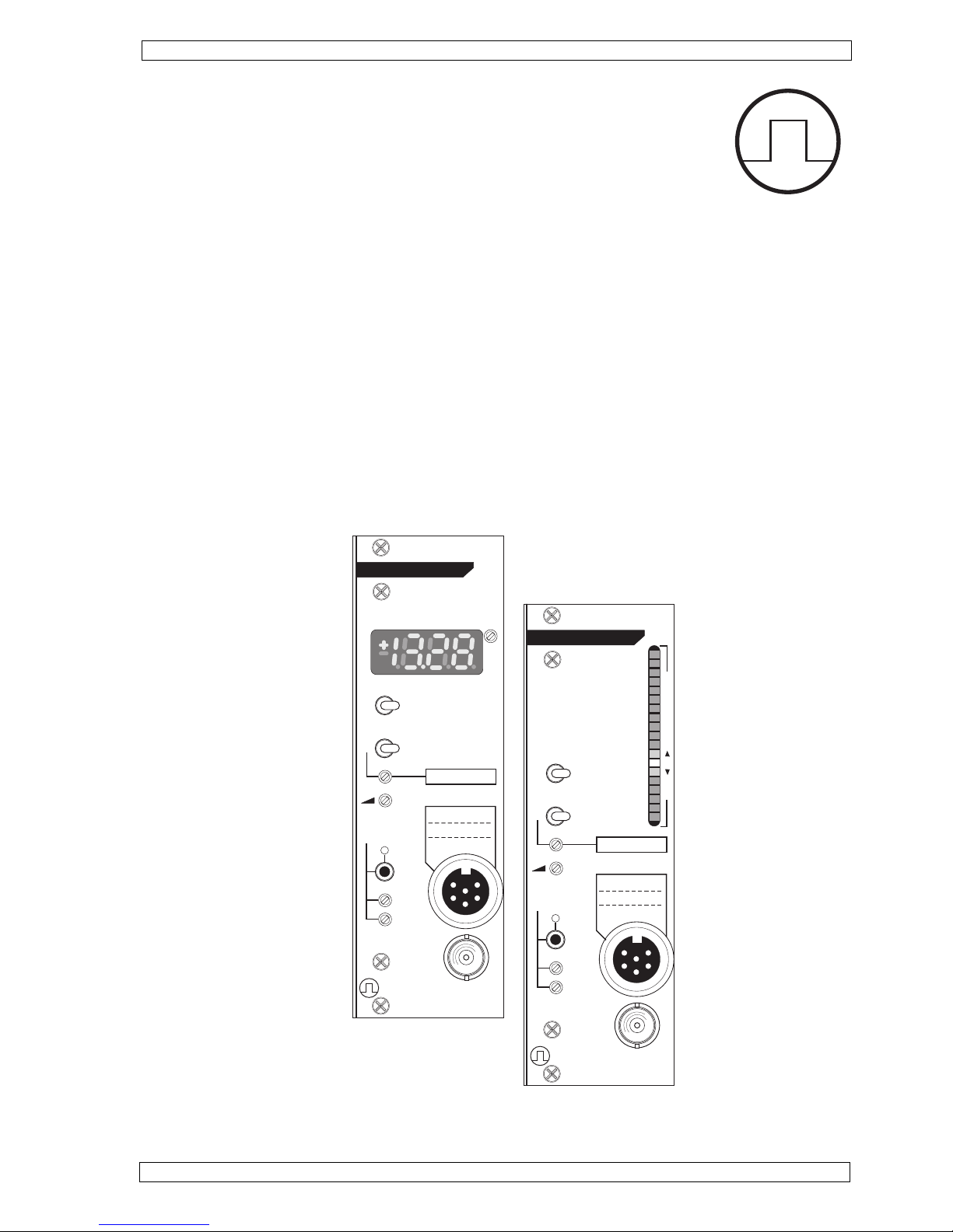
Version TAM-A Type 705/1 with bargraph display
Version TAM-D Type 705/2 with digital display
(Version 1.4 / printet: June 2013 / Hellstab / TB / Zi)
OPERATING INSTRUCTIONS
TAM-D
HUGO SACHS ELEKTRONIK
D-79232 MARCH GERMANY
TRANSDUCER
AMPLIFIER MODULE
CAL MEASURE
OFF
1
300
100 FILTER (Hz)
GAIN
20-100%
OUTPUT
(± 10V)
TYPE 705/2
AUTO
FINE
COARSE
ZERO
REF.
TRANSDUCER
HSE
ADJ.
135
2
4
6
300
135
2
4
6
FILTER (Hz)
TAM-A
HUGO SACHS ELEKTRONIK
D-79232 MARCH GERMANY
TRANSDUCER
AMPLIFIER MODULE
CAL MEASURE
OFF
1
100
GAIN
20-100%
OUTPUT
(± 10V)
TYPE 705/1
AUTO
FINE
COARSE
ZERO
REF.
TRANSDUCER
25
0
25
50
75
HSE
NOT FOR HUMAN USE

Page 2
HUGO SACHS ELEKTRONIK - HARVARD APPARATUS GmbH D-79232 March-Hugstetten Germany
HSE PLUGSYS® TAM-A Type 705/1 and TAM-D Type 705/2
Contents
1 Introduction, manufacturer's details .............................................................................................................. 3
1.1 Copyright .................................................................................................................................................. 3
1.2 Trademark ................................................................................................................................................. 3
2 Safety note .................................................................................................................................................. 3
3 General description, application .................................................................................................................. 4
4 Installing the module in a housing ............................................................................................................... 4
4.1 Installation procedure ............................................................................................................................... 4
4.2 Internal settings, jumpers.......................................................................................................................... 5
4.2.1 Protection against electrostatic discharges (ESD) ................................................................................. 5
4.2.2 Location of the jumpers for the internal instrument adjustments ............................................................ 6
4.2.3 Input configuration of the amplifier (jumper J7) ...................................................................................... 7
4.2.4 Amplification GAIN (jumper J2) ............................................................................................................... 7
4.2.5 Autozero coupling (jumper J8) ................................................................................................................ 9
4.2.6 Filter setting mean output MEAN (jumper J3) ......................................................................................... 9
4.2.7 BNC socket Puls. or mean output (jumper J4) ........................................................................................ 9
4.2.8 Internal signal outputs PULSE and MEAN (jumper J5) ........................................................................... 9
4.2.9 Setting of the decimal point TAM-D (jumper J1) ..................................................................................... 10
4.2.10 Mean value filter digital display TAM-D (jumper J6) ..............................................................................10
4.3 Signal input ..............................................................................................................................................10
5. Controls TAM-A........................................................................................................................................ 11
5.1 Controls TAM-D ........................................................................................................................................ 12
6. Start-up .................................................................................................................................................... 13
6.1 Transducer calibration ..............................................................................................................................13
6.1.1 Basic setting for transducer calibration .................................................................................................. 13
6.1.2 Transducer calibration TAM-A ................................................................................................................ 14
6.1.3 Transducer calibration TAM-D with a digital voltmeter or a DAQ system ................................................15
6.1.4 Transducer calibration on a TAM-D with using the digital display (procedure for users who
don´t have a digital voltmetern nor a DAQ system ..................................................................................16
7. Zero compensation ZERO ......................................................................................................................... 17
7.1 Manual zero adjustment ...........................................................................................................................17
7.2 Automatic zero adjustment....................................................................................................................... 17
8. Filter 30 - 100 - 300 Hz .............................................................................................................................. 18
9. Maintenance notes.....................................................................................................................................18
9.2 Technical data TAM .................................................................................................................................. 19
Index ...............................................................................................................................................................20
Reply Form ........................ ..........................................................................................................................21
Application notes ..........................................................................................................................................22

Page 3
HUGO SACHS ELEKTRONIK - HARVARD APPARATUS GmbH D-79232 March-Hugstetten Germany
HSE PLUGSYS® TAM-A Type 705/1 and TAM-D Type 705/2
March-Hugstetten, June 2008
1 Introduction, manufacturer's details
1.1 Copyright
This product and the corresponding documentation are protected by copyright. All rights reserved. This document must not be copied, photocopied, reproduced or translated, either as a whole or in parts, without prior
written agreement by HUGO SACHS ELEKTRONIK - HARVARD APPARATUS GmbH, March/Hugstetten, Germany.
PLUGSYS® is a registered trademark of HUGO SACHS ELEKTRONIK - HARVARD APPARATUS GmbH,
March-Hugstetten. Other trademarks shown in the Operating Instructions are the property of the corresponding applicant.
2 Safety note
the equipment is designed for use in general laboratories, light industrial and office environments.
Operation in hazardous areas and/or in a flammable atmosphere is not permitted.
1.2 Trademark
Warning:
All the information in these Instructions has been drawn up after careful examination but does not
represent a warranty of product properties. Alterations in line with technical progress are reserved.
These Operating Instructions describe the function and use of the TAM-A Module Type 705/1 and the TAM-D
Module Type 705/2. They are part of the plug-in module and have to be kept close to it. The information provided
on the TAM has to be read in conjunction with the remaining system documentation of the PLUGSYS housing.
This PLUGSYS module is manufactured by
HUGO SACHS ELEKTRONIK HARVARD APPARATUS GmbH
Gruenstrasse 1,
79232 March-Hugstetten
Phone (Germany) :
Phone (others) :
Fax (Germany) :
Fax (others) :
eMail:
07665-9200-0
(int + 49) 7665-9200-0
07665-9200-90
(int + 49) 7665-9200-90
sales@hugo-sachs.de

Page 4
HUGO SACHS ELEKTRONIK - HARVARD APPARATUS GmbH D-79232 March-Hugstetten Germany
HSE PLUGSYS® TAM-A Type 705/1 and TAM-D Type 705/2
3 General description, application
The transducer amplifier module TAM is equipped, depending on the version, either with analogue
(TAM-A) or digital (TAM-D) display. Apart from a few exceptions, the amplifiers of the
two versions are identical. In the description below, the symbol TAM refers to both
module versions. The symbol TAM-A or TAM-D is used when referring to the different
properties of the two amplifier variants.
The amplifier module TAM is a univeral DC bridge amplifier. In conjunction with a suitable resistive transducer
it permits direct measurement of e.g. force, pressure or displacement. The amplifier is arranged as a plug-in
module of the PLUGSYS measuring system and is operated inside a PLUGSYS housing.
TAM-A (Type 705/1) is equipped with a LED line, a so-called bargraph. Visual analogue presentation of the
measured signal, is ideally suitable for monitoring dynamic signals.
TAM-D (Type 705/2) carries a 3½-digit LED display. It is therefore particularly suitable for evaluating static
signals. The instantaneous measurement can be read directly on the numerical display of the TAM-D. By
calibrating the module to the transducer it is possible to adjust the sensitivity of the display so that the measurement can be read off directly (e.g. force in ±100 mN, pressure in ±200 mm Hg, displacement in ±4 mm etc.).
The amplification (Gain) of the TAM can be adjusted over a very wide range (x2 to x10 000) to suit the requirements of the transducer. The DC supply (excitation voltage) for the transducer is fixed at 5 V, the value commonly employed today.
As a special feature, both amplifiers TAM-A and TAM-B are equipped with automatic zeroing in addition to
manual zero adjustment.
In order to have an easy calibration of a connected data acqusistion system a predefinded value eg. 10mN,
100mmHg or 5mm can be simulated on the output.
The output filter 30-100-300 Hz is used for smoothing the signal. It acts on both signal
outputs PULSE (internal) and BNC socket (front panel). The internal signal output MEAN is preceded by a lowpass filter of 0.1 or 0.3 Hz. As an option the MEAN output can be connected to the BNC socket on the front panel
through an internal jumper on the circuit board.
4 Installing the module in a housing
The TAM module is designed as a PLUGSYS module and has a width of 8E corresponding to two slots. It can
be installed directly in any housing with a system bus. An exception is the PLUGSYS MiniCase Type 609; the
TAM can also be operated in this housing but installation requires some soldered connections and it is therefore only supplied completely installed from the factory.
If you bought your module installed in a housing these adjustments already have been made in the factory
prior to shipping.
Switch off the housing and pull out the mains plug.R
Remove the blank panel at the housing slot position intended for the TAM module.R
Make the internal adjustments according to Section 4.2.R
Insert the TAM module, note the guide rails.
R
Firmly push in the module, it must clearly engage with the bus connector.
R
Screw on the front panel, reconnect the mains cable to the housing, and plug in the transducer.
R
Before the module is installed in a housing it is necessary to make a number of internal adjustments. First it is
necessary to carry out the adjustments described in Section 4.2. Note the precautions described in Section
4.2.1 which are absolutely essential in order to avoid electrostatic discharges.
Brief procedure (for full details see the Operating Manual of the housing):
4.1 Installation procedure

Page 5
HUGO SACHS ELEKTRONIK - HARVARD APPARATUS GmbH D-79232 March-Hugstetten Germany
HSE PLUGSYS® TAM-A Type 705/1 and TAM-D Type 705/2
4.2.1 Protection against electrostatic discharges (ESD)
Equilibrate potentials by touching earthed metal objects, e.g. housing of some electrical equipment
connected to the supply, central heating radiator etc.
R
In order to avoid fresh electrostatic charges, do not move unnecessarily backwards and forwards on
your working area. Where available, it is best to wear an antistatic wristband for continuous discharge of
static electricity.
R
When you remove the TAM from its antistatic packaging, touch first the front panel of the module to
equilibrate the potentials.
R
For the internal adjustments place the module flat on the foil of the antistatic packaging.R
Take care in handling the amplifier module, avoid bending the circuit board and unnecessary touching of
its components.
R
Before inserting the module in the housing, ensure potential equilibration between the module, yourself
and the housing. First touch the metal housing before inserting the TAM.
R
When handling the module during use it is equally important to ensure that no electrostatic discharges
take place through the inner pins of the input or output sockets. For this reason you should always first
provide potential equilibration between yourself, the PLUGSYS and the transducer or recording system.
4.2 Internal settings, jumpers
In order to adjust the TAM to the individual application the following settings have to be made with jumpers on
the module circuit board. See diagrams next page !
R
R
R
Jumper J1 (TAM-D only): position of decimal point on the digital display
Jumper J2: gain of the input amplifier GAIN x1 - x1000 (the overall gain is 10x higher due to the subse-
quent output amplifier)
Jumper J3: time constant for the MEAN output 0.1 or 0.3 Hz
R
Jumper J4: PULSE or MEAN output at the BNC socket on the front panel
R
Jumper J5: bus lines AV1 - 16 for the internal signal outputs PULSE and MEAN
R
Jumper J6: (TAM-D only) input filter of digital display SLOW - FAST
R
Jumper J7: input selection between transducer with resistance bridge circuit (POS.2) or voltage input
from transducer with integrated amplifier (POS.1)
R
Jumper J8: to adjust the calibration range of the autozero to the selected amplification and the internal
resistance of the transducer.
Modern electronic components are very sensitive to electrostatic discharges. Even the smallest electrostatic
charge may damage the electronics or lead to faults. Therefore follow the steps described below in order to
discharge any possible static electricity on your body.
Tip
Page 6
HUGO SACHS ELEKTRONIK - HARVARD APPARATUS GmbH D-79232 March-Hugstetten Germany
HSE PLUGSYS® TAM-A Type 705/1 and TAM-D Type 705/2
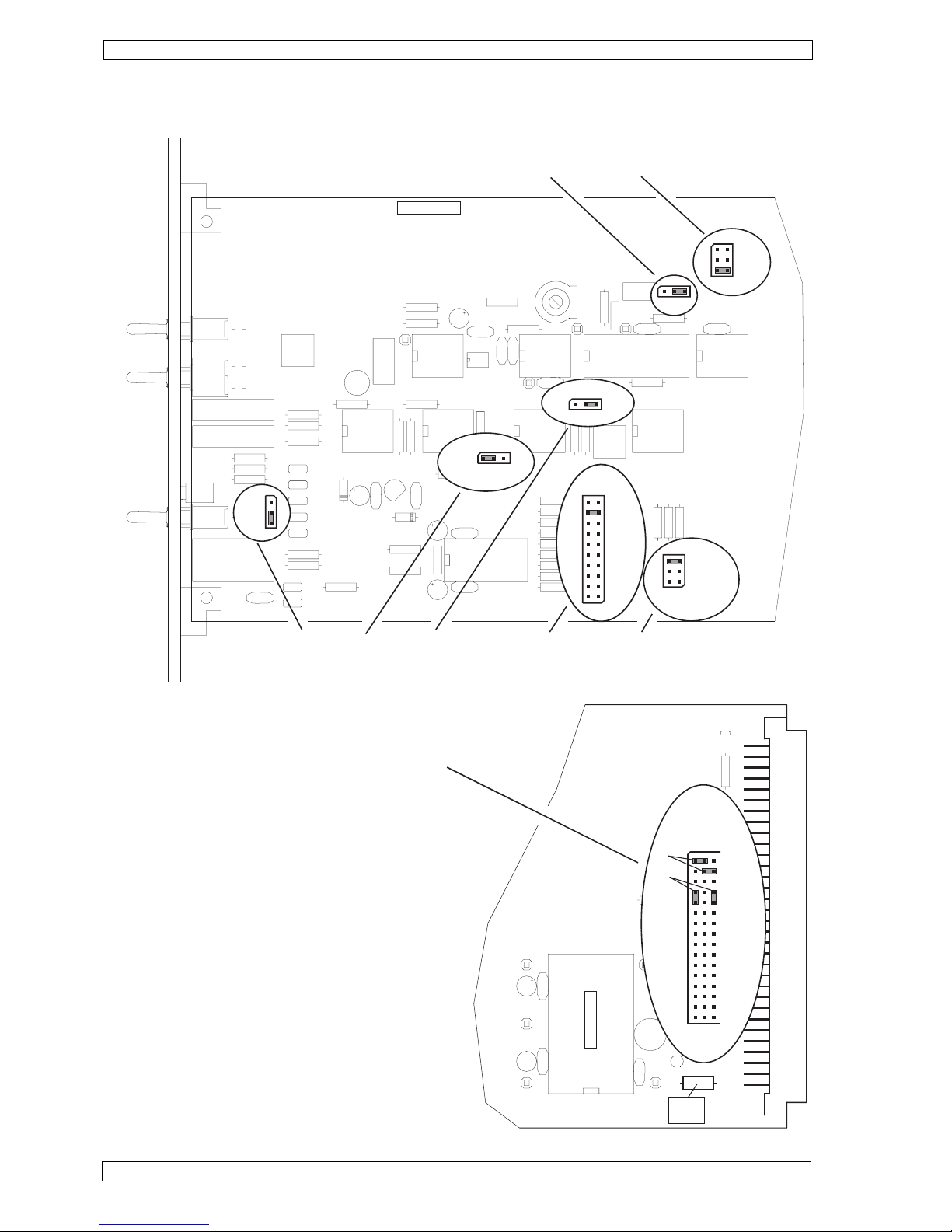
4.2.2 Location of the jumpers for the internal instrument adjustments
fuse
1A/SF
1
32
DGND
-15V
AGND
+15V
TEM 3-0522
+5V
(+5V)
(DGND)
PULSE
AV 1-16
MEAN
10
11
12
13
14
15
16
A
B
1
2
3
4
5
6
7
8
9
FILE: TAM_DP1.FH3
J7
DP 705-1/b
J4 J3 J2 J8
J6
J1
x1000
x500
x200
x100
x50
x20
x10
x5
x2
x1
GAIN
DP-2
DP-3
DP-4
J1
SLOW - FAST
J6
POS.1
POS.2
0.1Hz
0.3Hz
Filter MEAN
PULSATILE
MEAN
OUTPUT
(front panel)
A (low)
B (mean)
C (high)
RANGE of AUTO ZERO
J5
In the circle asside you see 3 coulums of pins.
On all left pins the pulsatile signal is available
The center pins are connected to the bus lines AV1 ...
AV16
On all right pins you have the filtered mean signal
avaialable.
T o connect e.g. the pulsatile pressure signal to signal
line AV1 set the jumper as described in A (upper left
jumper).
In this example the second jumper connects the
MEAN signal to analog line AV2
B shows the jumpers in park position if the rear
analog output is not used.

Page 7
HUGO SACHS ELEKTRONIK - HARVARD APPARATUS GmbH D-79232 March-Hugstetten Germany
HSE PLUGSYS® TAM-A Type 705/1 and TAM-D Type 705/2
4.2.3 Input configuration of the amplifier (jumper J7)
As a first step the operating mode of the input amplifier has to be selected to suit the type of transducer.
The most widely used transducers are based on a resistance bridge circuit (Wheatstone bridge) with an internal resistance in the range 100 - 1000 Ohm. The input amplifier has to be switched to push-pull input (differential amplifier), Jumper J7 on POS.2.
R2
R4
R3
R1
excitation voltage (+)
signal (+)
excitation voltage (-)
signal (-)
case, shield
Typical arrangement of a transducer with bridge circuit
Less widely used are transducers with built-in preamplifier. Depending on type, the measurement signal is
amplified by these active transducers up to the Volt range. The input amplifier of the TAM is switched as
straight amplifier, Jumper J7 on POS.1
case, shield
Transducer
+
Amp.
Output
Power (+)
Power (-)
Sig. GND
Typical arrangement of a transducer with preamplifier
In order to avoid damage to the electronics of the transducer, check first that a supply voltage of
5 Volt (50 mA) can be used as bridge supply. Special attention must be paid to correct polarity.
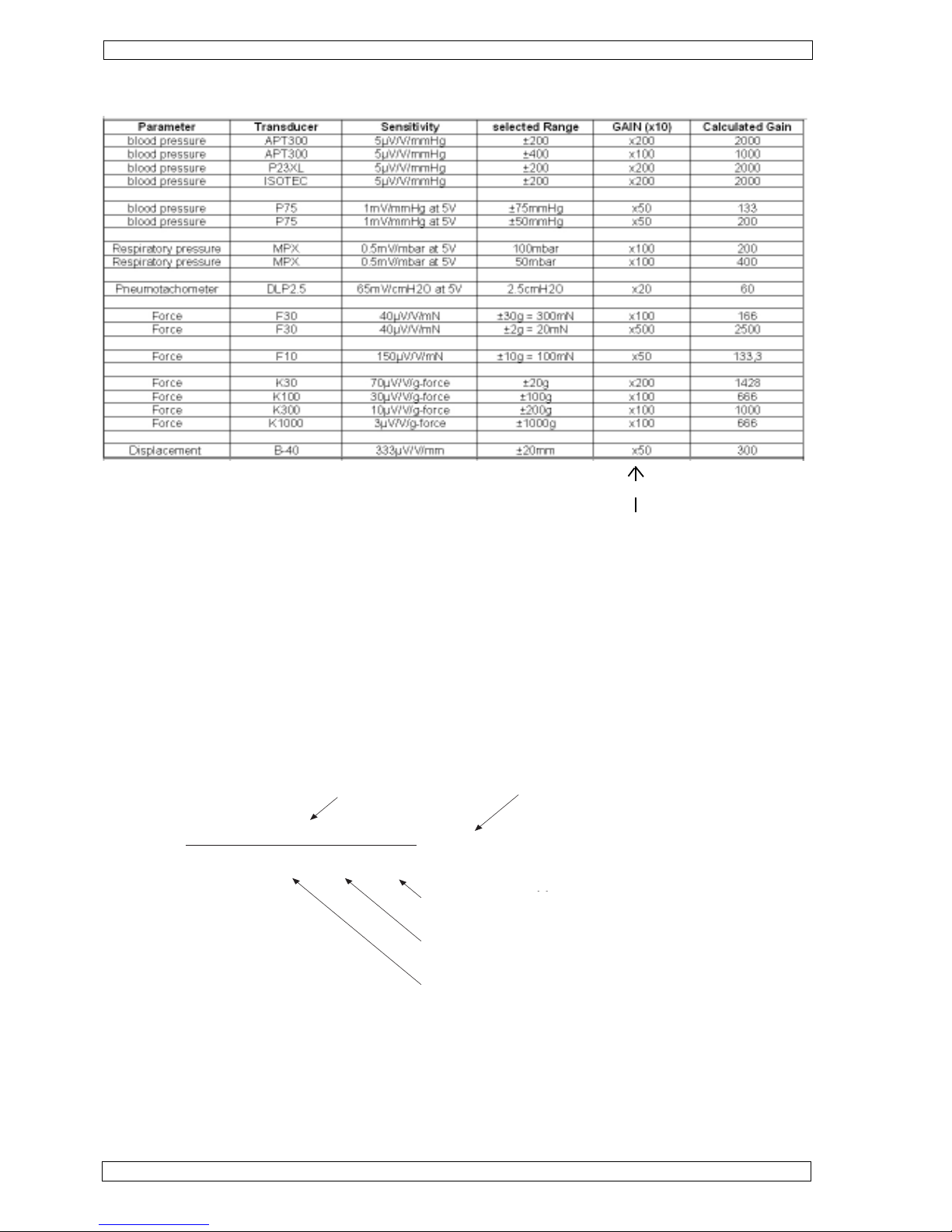
4.2.4 Amplification GAIN (jumper J2)
The amplification of the TAM can be adjusted over a very wide range (x2 - x10 000) to suit the requirements of
the transducer. The amplification to be set depends essentially on the sensitivity of the transducer (amplitude
of the measurement signal) and on the required measuring range.
The selected gain of the preamplifier x1 / x2 / x5 / x10 / x20 / x50 / x100 / x200 / x500 / x1000 is
multiplied by 10 due to the additional fixed gain of 10 of the output amplifier.
Note
Warning
Page 8
HUGO SACHS ELEKTRONIK - HARVARD APPARATUS GmbH D-79232 March-Hugstetten Germany
HSE PLUGSYS® TAM-A Type 705/1 and TAM-D Type 705/2
With a known transducer sensitivity (e.g. Isotec transducer 5.05 µV / Volt supply / mm Hg)
the gain is calculated as follows:
Range ±200 mmHg (can be selected individually)Details:
Bridge supply voltage 5 Volt (fixed)
Output voltage range of TAM ±10 V (fixed)
Transducer sensitivity 5.05 µV / Volt supply / mm Hg (see transducer data sheet)
As the GAIN fine trimmer does only allow gain reduction, the gain jumper should allways be set to the next higher
possible value. In the example above the gain should be set to 200. This gives an overall amplification of 200
(preamplifier) times 10 (output amplifier), equal to 2000x. The exact adjustment of the gain to 1980 is made
through the transducer calibration on the front trimmer "GAIN 20-100%".
10
((5.05 x 10
-6
) x 5 x 200)
= 1980.2
output voltage in volt
gain required
range on mm Hg
bridge suply voltage
transducer sensitivity
e.g. 5.05 µV/V/mm Hg
range in mm Hg
The table below provides information on typical amplifier adjustments for standard transducers and applications.
Set GAIN on board with Jumper J2
 Loading...