

HSE AFA 500 Operating And Instruction Manual
AFA 500
FUME HOOD ALARM
Operating and Instruction Manual
Used for alarm indication and monitoring on Fume Hoods
5/MK3/FH/USPSU
280304
Model AFA 500
• Built-in or Remote sensor
• 2 Relay inputs
• 1 Relay output
• Com port
1

Table of contents
Section
1
:-
Description
Operator display panel
Page
3
2
3
4
5
6
7
8
9
10
Connection details
General description – overview
Alarm Configuration / Calibration
Start-up
Events – actions
Quick Start Installation / Calibration
Dimensions
Aiflow Alarm Installation
Wiring diagram
4
5 to 6
7
7
8
9 to 10
11
12 to 14
15
11
12
Limitation of Warranty and Liability
13
Spare parts
Contact us
16
17
17
2
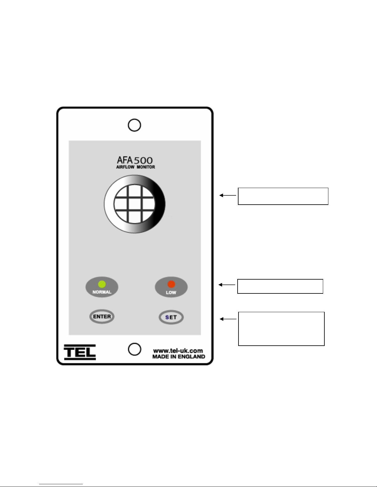
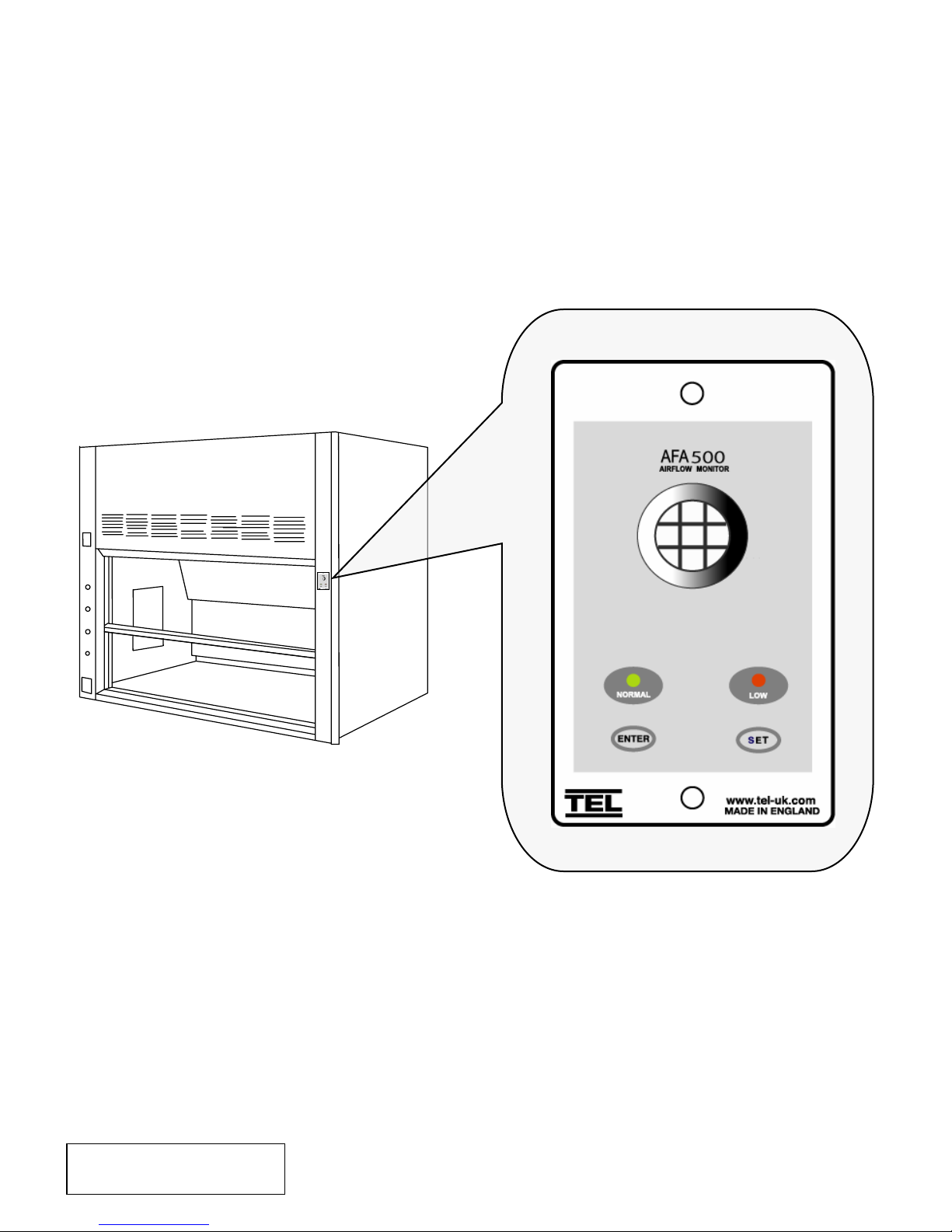
1.0 Operator Display Panel
Built-in AIRFLOW SENSOR
LED indicators
Function buttons Calibration.
ENTER – also used as
Mute button for audible alarm
3
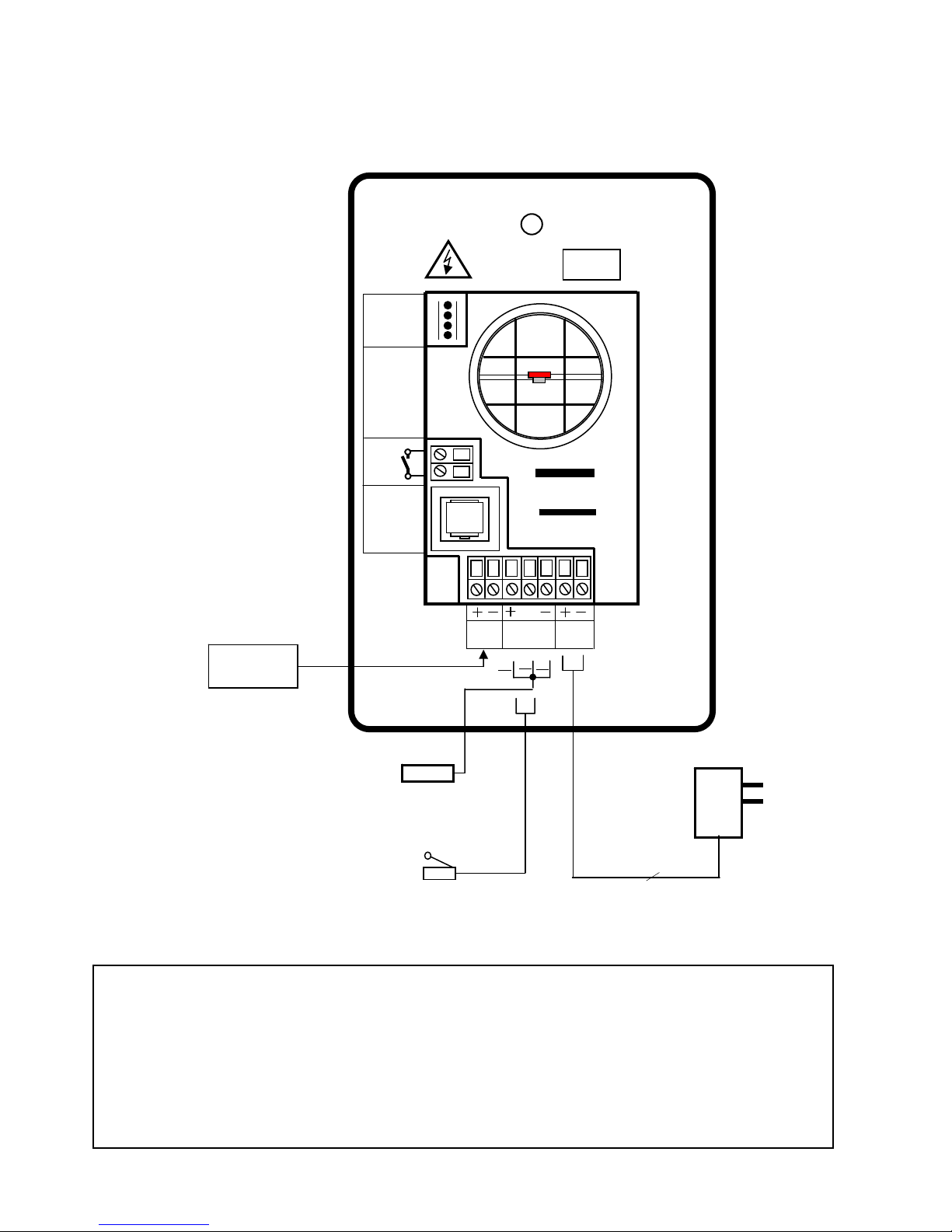
2.0 Connection details
A
T
RS 232
Com Port
OUTPUT
RE AY L
R1
OPTIONAL
REMOTE
AIRFLO W
SENSOR
SOCKET
Night set-back
Relay input
Sash High
Proximity switch
( Optional )
Sash High
Micro - switch
( Optional )
Notes:-
1. The Sash High alarm can operate with the Micro switch OR the Proximity Switch.
Both connection points are available as standard.
2. Inputs 1 & 2 are volt free inputs. (Max line resistance 4.7K ohms) (Short circuit current 5mA DC)
3. Relay output R1 is a power limited volt free contact. Contact rating 30VAC / 42VDC Max
3.0 General Description
4. Primary power requirement - 110mA @ 120VAC ( 3A Fused supply recommended ).
REFER TO
INSTALLATION
INSTRUCTIONS
BEFORE
CONNECTING
INPUT
1
Brn
MADE IN ENGLAND
www.tel-uk.com
s/w
INPUT
2
Blk
Blu
FA 500
USA
EL
15V DC
POWER
SUPPLY
Flying lead with plug
connection for PCB
15 V DC
PSU
120V / 15V DC
Plug – in power adapter
for 120V socket
Power requirement –
110mA @ 120VAC.
4

All systems comprise of the following components :-
1 – AFA 500 Alarm unit,
1 – AC power supply
If the Sash Alarm System option is ordered there will also be a sash micro switch
or proximity switch.
Operator Features --- the alarm has the following operator features :-
Normal Airflow - Green LED (Not flashing) will be displayed if the airflow is
greater than the Low air alarm point.
Low Airflow - Red LED (Not flashing) will be displayed if the airflow is lower
than the Low air alarm point.
Sash High - Red LED (Flashing) will be displayed when the Sash is raised
above the max safe working opening.
Audible Alarm -- the Audible alarm will sound ( can be muted ) in the Air Low
and the Sash High alarm condition
Night Setback -- when the Night Setback input is activated the Audible alarm
will be muted and the Green LED will flash on/off
ENTER --- the alarm has an Enter button -- this is multi-functional as follows : Press Enter momentarily when Low Air alarm is sounding will mute
the alarm
Press Enter momentarily when Sash High alarm is sounding will
mute the alarm and initiate a repeat timer that will re-sound the alarm
if the Sash is not lowered to a safe position before the end of the time
period
Press Enter for 5 secs will gain access to Calibration mode
SET -- used during the airflow Calibration of the alarm
5

External Connections -- the alarm unit has the following connection points :Input 1 --- volt free relay input – ( close contact to activate the input )
This input is configured as :- NIGHT SETBACK
Output R1 --- volt free relay output - ( contact closes on activation )
This input is configured as :- LOW AIR ALARM
Sash High Input: a. Connection point for Sash High micro switch.
( Switch contact to close and remain closed in
Sash High condition )
b. Connection point for Sash High proximity switch.
( Switch contact to close and remain closed in
Sash High condition )
Note:- Use input a. OR input b. for the Sash High alarm
Com Port --- to enable connection to Laptop or PC for full diagnostics , logging
or setting up and for communications to building computer system
( BMS)
Power supply --- low voltage DC power supply 15V DC
6
 Loading...