

HSD ES915, ES919 NL, ES919 L NC, ES919 NC, ES919 L NL Installation, Operation And Maintenance Manual
Installation, Operation and Maintenance Manual
5801H0017
Revision 02
ELECTRO-SPINDLES
for automatic tool changing
HSD S.p.a.
TECHNOLOGICAL EQUIPMENT FOR AUTOMATION
Via della Meccanica 16
Loc. Chiusa di Ginestreto
61100 PESARO (ITALIA)
Tel. (+39)0721.439.612
Fax(+39)0721.441.606
E-mail hsd.sales@hsd.it
Web: www.hsd.it
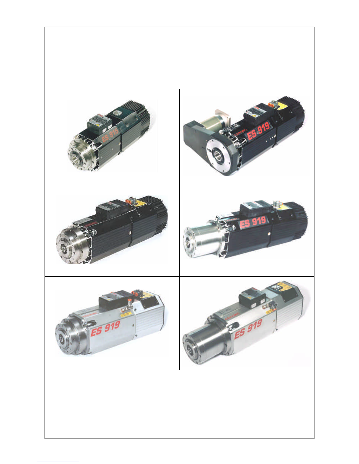
ES915
ES919 NC
WHITH BELT DRIVEN "C" AXIS UNIT
ES919 NC
ES919 NL
ES919 L NC
ES919 L NL

______HSD Technological equipment for Automation _____________________________________
5801H0017 Rev. 02 __________________________________________________________ 2/98
TABLE OF CONTENTS
§ 1 DOCUMENTS DELIVERED WITH THE ELECTRO-SPINDLE......................................... 5
§ 2 DOCUMENT INFORMATION ........................................................................................... 5
§ 3 CUSTOMER ASSISTANCE SERVICE............................................................................. 5
§ 4 TERMS OF WARRANTY.................................................................................................. 6
§ 5 WARNINGS AND SAFETY PRECAUTIONS.................................................................... 7
5.1 Distribution of this manual .................................................................................................. 7
5.2 General safety symbols ....................................................................................................... 7
5.3 Risks associated with the electro-spindle.......................................................................... 8
5.4 Risks associated with improper use and handling............................................................ 8
5.5 Risks specific to maintenance............................................................................................. 9
§ 6 GENERAL INFORMATION............................................................................................... 9
6.1 Proper use of the product.................................................................................................... 9
6.2 Identification of manufacturer and part ............................................................................ 10
6.3 Description of the main parts of the electro-spindle........................................................ 11
6.4 Glossary.............................................................................................................................. 12
§ 7 TECHNICAL SPECIFICATIONS..................................................................................... 13
7.1 Available models................................................................................................................ 13
7.1.1 ES915 / ES915 L ........................................................................................................ 13
7.1.2 ES919 / ES919 L ........................................................................................................ 13
7.2 Technical specifications of ES915 .................................................................................... 14
7.2.1 Overall dimensions of ES915........................................................................................ 14
7.2.2 Specifications and performance of ES915 2 Pole, 3.8 kW units.................................... 15
7.2.3 Specifications and performance of ES915 4 Pole, 5 kW units....................................... 16
7.3 Technical specifications of ES915 L................................................................................. 17
7.3.1 Overall dimensions of ES915 L HSK F63 Long Nose.................................................. 17
7.3.2 Specifications and performance of ES915 L 4 Pole, 7.5 kW units ................................. 18
7.4 Technical specifications of ES919 .................................................................................... 19
7.4.1 Overall dimensions of ES919 ISO30 Short Nose .......................................................... 19
7.4.2 Overall dimensions of ES919 ISO30 Long Nose........................................................... 20
7.4.3 Overall dimensions of ES919 HSK F63 Short Nose...................................................... 21
7.4.4 Overall dimensions of ES919 HSK F63 Long Nose....................................................... 22
7.4.5 Specifications and performance of ES919 2 Pole, 7 kW units....................................... 23
7.4.6 Specifications and performance of ES919 2 Pole, 8 kW units....................................... 24
7.4.7 Specifications and performance of ES919 4 Pole, 5.5 kW units.................................... 25
7.4.8 Specifications and performance of ES919 4 Pole, 7.5 kW units.................................... 26
7.5 Technical specifications of ES919 L................................................................................. 27
7.5.1 Overall dimensions of ES919 L ISO30 Short Nose ...................................................... 27
7.5.2 Overall dimensions of ES919 L ISO30 Long Nose....................................................... 28
7.5.3 Overall dimensions of ES919 L HSK F63 Short Nose.................................................. 29
7.5.4 Overall dimensions of ES919 L HSK F63 Long Nose ................................................... 30
7.5.5 Specifications and performance of ES919 L 4 Pole, 12 kW units ................................. 31
7.6 Technical specifications of Belt driven C axis unit.......................................................... 32
7.6.1 Overall dimensions of ES919 ISO30 Short Nose with belt driven C Axis unit................ 32
7.6.2 Overall dimensions of gear units................................................................................... 33
7.6.3 Technical specifications for belt driven C axis unit ........................................................ 34
7.7 Technical specifications of components.......................................................................... 35
7.7.1 Bearings........................................................................................................................ 35
7.7.2 Tool holder locking and release device ......................................................................... 35
7.7.3 Automatic cleaning of the tool holder and internal pressurization.................................. 36
7.7.4 Proximity sensors.......................................................................................................... 36

______HSD Technological equipment for Automation _____________________________________
5801H0017 Rev. 02 __________________________________________________________ 3/98
7.7.5 Tool release button....................................................................................................... 36
7.7.6 Thermal switch.............................................................................................................. 37
7.7.7 Cooling fan.................................................................................................................... 37
§ 8 TRANSPORT AND MOVING.......................................................................................... 38
8.1 Storage................................................................................................................................ 38
8.2 Lifting the electro-spindle in its crate............................................................................... 38
§ 9 INSTALLATION.............................................................................................................. 40
9.1 First Check .......................................................................................................................... 40
9.2 Preparation of the equipment required for installation on site ....................................... 40
9.3 Mechanical installation ...................................................................................................... 40
9.3.1 The supporting surface ................................................................................................. 40
9.3.2 Positioning the electro-spindle ...................................................................................... 40
9.3.3 Mechanical fixing of the electro-spindle ......................................................................... 41
9.3.4 Threaded service holes................................................................................................. 42
9.4 Compressed air connections............................................................................................. 43
9.4.1 Compressed air unions................................................................................................. 43
9.4.2 Functional diagram of electro-spindle compressed air connections............................... 44
9.5 Cooling circuit .................................................................................................................... 45
9.5.1 Cooler specifications..................................................................................................... 45
9.6 Electrical connections........................................................................................................ 46
9.6.1 Connectors ................................................................................................................... 46
9.6.2 Pin layout of fixed signals connector - ISO 30 version................................................... 46
9.6.3 Pin layout of fixed signals connector - HSK F63 version ............................................... 47
9.6.4 Pin layout of fixed power connector............................................................................... 47
9.6.5 Tool holder release system electrical wiring diagram for electro-spindles not controlled by
CNC.............................................................................................................................. 48
9.6.6 Configurable power terminals (optional)........................................................................ 49
§ 10 GENERAL CHECKS AFTER INSTALLATION AND DURING START-UP.................. 50
10.1 Checking the electro-spindle before start-up................................................................. 50
10.2 Checking the electro-spindle on first start-up................................................................ 51
§ 11 OPERATING THE ELECTRO-SPINDLE...................................................................... 52
11.1 Climatic conditions .......................................................................................................... 52
11.2 Running in......................................................................................................................... 52
11.3 Warming up....................................................................................................................... 52
11.4 Selecting the tool holder and tool ................................................................................... 53
11.4.1 ISO 30 tool holders ..................................................................................................... 53
11.4.2 HSK F63 tool holders.................................................................................................. 54
11.4.3 General safety precautions for tool holders................................................................. 55
11.4.4 Choosing tools............................................................................................................ 56
11.5 Speed limitations.............................................................................................................. 57
11.5.1 Content of graphs ....................................................................................................... 57
11.5.2 Reading the graphs..................................................................................................... 57
11.5.3 ES915 ISO30............................................................................................................. 58
11.5.4 ES919 ISO30 Short Nose , ES919 L ISO30 Short Nose ...................................... 59
11.5.5 ES919 ISO30 Long Nose , ES919 L ISO30 Long Nose........................................ 60
11.5.6 ES919 HSK F63 Short Nose , ES919 L HSK F63 Short Nose.............................. 61
11.5.7 ES919 HSK F63 Long Nose , ES919 L HSK F63 Long Nose............................... 62
11.6 Sensor functioning........................................................................................................... 63
11.6.1 ISO 30 versions .......................................................................................................... 63
11.6.2 HSK F63 versions....................................................................................................... 64
11.7 Thermal switch ................................................................................................................. 65
§ 12 MAINTENANCE............................................................................................................ 66
12.1 Scheduled maintenance................................................................................................... 67
12.1.1 Checking the cleanliness of the tool holder cone and of the spindle shaft tool housing67

______HSD Technological equipment for Automation _____________________________________
5801H0017 Rev. 02 __________________________________________________________ 4/98
12.1.2 Cleaning the tool holder cone...................................................................................... 69
12.1.3 Protecting the spindle shaft's conical housing ............................................................. 69
12.1.4 Lubricating HSK fingers .............................................................................................. 70
12.1.5 Bearings...................................................................................................................... 70
12.2 Replacing parts................................................................................................................. 71
12.2.1 Changing the spindle shaft kit ..................................................................................... 72
12.2.2 Replacing the cooling fan............................................................................................ 74
12.2.3 Replacing the tool change push-button....................................................................... 74
12.2.4 Replacing sensors S1, S2, S3 and S4......................................................................... 75
12.2.4.1 Wiring of sensors in ISO 30 versions...............................................................................75
12.2.4.2 Wiring of sensors in HSK versions...................................................................................75
12.2.4.3 Accessing the sensors.....................................................................................................76
12.2.4.4 Location of sensors..........................................................................................................76
12.2.4.5 The sensor assembly.......................................................................................................77
12.2.4.6 Replacing a sensor assembly..........................................................................................77
12.2.4.7 Calibrating sensors S1, S2, and S3 on ISO 30 electro-spindles .....................................78
12.2.4.8 Calibrating sensors S1, S2, S3 and S4 on HSK F63 electro-spindles ............................78
12.2.4.8.1 Procedure for S1..............................................................................................78
12.2.4.8.2 Procedure for S2..............................................................................................78
12.2.4.8.3 Procedure for S3..............................................................................................79
12.2.4.8.4 Procedure for S4..............................................................................................79
12.2.4.9 Gauge and shim kit for calibrating S1 and S4 sensors on HSK F63 electro-spindles
(HSD code 3811H0110).......................................................................................................80
12.2.4.10 Calibrating sensors S1 and S4 on F63 HSK electro-spindles using the 3811H0110 kit80
12.2.4.10.1 Procedure for S1............................................................................................81
12.2.4.10.2 Procedure for S4............................................................................................81
12.2.5 Replacing the cylinder assembly................................................................................. 82
§ 13 ACCESSORIES AND OPTIONS .................................................................................. 85
13.1 "Spindle shaft stopped" sensor S3................................................................................. 85
13.2 Bearing temperature sensor............................................................................................ 85
13.2.1 Installing the bearing temperature sensor ................................................................... 86
13.2.2 Characteristic curve of the temperature sensor referred to 1 mA............................... 86
13.3 “C” axis unit...................................................................................................................... 87
13.3.1 Belt driven “C” axis unit............................................................................................... 87
13.3.2 Gear driven “C” axis unit ............................................................................................. 87
13.3.3 SC sensor for the belt driven “C” axis unit................................................................... 88
13.3.4 Replacing and calibrating the SC sensor in belt drive versions.................................... 89
13.4 Forced air cooling ............................................................................................................ 91
13.4.1 Installing the forced air cooling kit ............................................................................... 91
§ 14 TROUBLE SHOOTING................................................................................................. 92
§ 15 SPARE PARTS LIST.................................................................................................... 96
§ 16 DISPOSING OF THE ELECTRO-SPINDLE.................................................................. 97
______HSD Technological equipment for Automation _____________________________________
5801H0017 Rev. 02 __________________________________________________________ 5/98
§ 1 DOCUMENTS DELIVERED WITH THE ELECTRO-SPINDLE
The following documents are delivered with the electro-spindle:
• this manual containing the safety warnings and instructions for installation, operation and
maintenance
• a series of other documents including:
1. The Manufacturer's Declaration of conformity to attachment IIB of Directive 98/37/CE
2. Attachments containing information on special parts of the electro-spindle. All such
attachments must be consulted in conjunction with the main document to which they refer in
order to avoid missing important information.
Make sure that all the above documents are delivered with the electrospindle. If any are missing, ask HSD S.p.a. for a replacement copy.
§ 2 DOCUMENT INFORMATION
This manual has been written by the Electro-spindle department of the Technical Office at HSD
S.p.a. for use by all the installers, operators and service engineers who work with the electrospindle.
ISSUED BY CODE REVISION APPROVED BY
HSD S.p.a.
Via della Meccanica 16
Loc. Chiusa di Ginestreto
61100 PESARO (ITALIA)
5801H0017 02 UTE 005 / 03
Record of updates
Revision Added § Deleted § Changed §
00 First issue First issue First issue
01 General revision General revision General revision
02 ES 915 L HSK F63 Long Nose ---- Overall dimensions of ES 919 L HSK F63 Long Nose
This manual is delivered as an essential part of the electro-spindle and at the time of revision was
the most up to date documentation on the product.
§ 3 CUSTOMER ASSISTANCE SERVICE
HSD HSD HSD
Via della Meccanica 16
61100 PESARO (ITALIA)
Loc. Chiusa di Ginestreto
Tel. (+39)0721.439.638
Fax (+39)0721.441.606
E-mail hsd.service@hsd.it
Web www.hsd-hitec.com
HSD Deutschland GmbH
Brückenstrasse 2
D-73333 Gingen
Tel. +49(0)7162 / 9323436
Fax +49(0)7162 / 9323439
HSD USA Inc.
3764 SW, 30th Avenue
Hollywood, Florida 33312 USA
Phone no. (+1) 954 587 1991
Fax (+1) 954 587 8338
E-mail service@hsdusa.com
Web www.hsdusa.com

______HSD Technological equipment for Automation _____________________________________
5801H0017 Rev. 02 __________________________________________________________ 6/98
§ 4 TERMS OF WARRANTY
HSD S.p.a. guarantees that this electro-spindle has been QC passed in testing in the factory. HSD
S.p.a. accepts responsibility only for defects in electrical and mechanical parts. The warranty does
not cover defects caused by the normal use of parts subject to continuous or rapid wear (e.g.
seals, belts, bearings, etc.). In particular HSD S.p.a. offers no guarantee as to the duration of
bearings, since bearing wear depends on various factors including: tool balancing precision, type
of machining operation, impacts and/or mechanical stress in excess of the manufacturer’s declared
limits.
HSD S.p.a. declines all responsibility for non-compliance of the electro-spindle caused by failure to
follow the precautions and instructions given in this manual or by improper use or handling of the
electro-spindle. The customer has the right to replacement of all parts shown to be defective,
unless the said defects are caused by unauthorized tampering, including the fitting of non-original
HSD spare parts and/or the replacement of parts not described or authorized in this manual unless
authorized beforehand and in writing by HSD S.p.A..
In no case shall HSD S.p.A. or its suppliers accept any responsibility for damage (including
damage to the unit, damage incurred for lost production and income, down-time in manufacturing,
loss of information or other economic losses) deriving from the use of HSD products, even if HSD
has been advised of such risks in advance.
The warranty becomes automatically null and void if the customer fails to notify HSD S.p.A. in
writing of any faults found in the electro-spindle within 15 days of their occurrence. The warranty
likewise becomes null and void if the customer fails to permit the seller to perform all necessary
checks and tests, and if, when the seller requests the return of a defective part, the customer fails
to do so within two weeks of the request.
Dimensioned drawings and photographs are provided only for information purposes and to
facilitate understanding of text.
HSD S.p.A. has a policy of constant development and improvement, and reserves the right to
make functional and stylistic modifications to its products, to change the design of any functional or
accessory part, and to suspend manufacturing and supply without notice and without obligation to
third parties. Furthermore, HSD S.p.A. reserves the right to make any structural or functional
change to the units, and to change the supply of spare parts and accessories without any prior
notice.
______HSD Technological equipment for Automation _____________________________________
5801H0017 Rev. 02 __________________________________________________________ 7/98
§ 5 WARNINGS AND SAFETY PRECAUTIONS
5.1 DISTRIBUTION OF THIS MANUAL
This manual contains important instructions and precautions, and must accompany the electrospindle at all times since it is essential for the safe operation of the electro-spindle.
Keep this manual safe, and ensure that all persons involved with the electro-spindle know of it and
have access to it.
The safety precautions contained herein are designed to ensure the safety of all persons
exposed to the residual risks associated with the electro-spindle.
The instructions contained herein provide information necessary for the correct operation of the
electro-spindle, as required by the manufacturer.
If any information given in this manual is found to be in conflict with applicable safety regulations,
contact HSD S.p.A. on +39 0721 439612 to request the necessary corrections and/or adaptations.
Make sure that you read and fully understand all the documentation supplied with the electrospindle to avoid incorrect operation of the unit and unnecessary risks of personal injury.
Keep this manual in a suitable place near the machine, where it will always be readily available to
operators for consultation.
IMPORTANT: The information given in this manual is essential to
ensure that the electro-spindle is installed and used safely and
correctly.
5.2 GENERAL SAFETY SYMBOLS
In this manual, important instructions or precautions are marked with the following symbols:
WARNING: Identifies situations that could lead to
personal injury.
WARNING: Live electrical parts.
i
IMPORTANT: Identifies particulary important
information.

______HSD Technological equipment for Automation _____________________________________
5801H0017 Rev. 02 __________________________________________________________ 8/98
5.3 RISKS ASSOCIATED WITH THE ELECTRO-SPINDLE
HSD does not and can not know how end users will install their electro-spindles. The
installer or customer must therefore perform risk assessment specific to each installation
and application.
It is also the responsibility of the installer to ensure that adequate guards are provided to prevent
accidental contact with moving parts.
The installer and the operator must also bear in mind other types of risk, particulary those
associated with foreign bodies, explosive, inflammable, toxic or high temperature gasses.
Risks associated with maintenance operations must also be guarded against. Maintenance must
be performed in conditions of maximum safety, and only with the electro-spindle fully stationary
and switched off.
Once the electro-spindle has been installed in the way decided upon by the installer and/or
customer, the machine becomes a “finished machine” as defined for the purposes of the Machinery
Directive. Overall risk assessment must therefore be performed on the finished machine and a
declaration of conformity produced in compliance with Appendix IIA of the 98/37/CE Machinery
Directive.
5.4 RISKS ASSOCIATED WITH IMPROPER USE AND HANDLING
• Never impede the functioning of, remove, modify or in any way interfere with any safety device,
guard, or control of individual parts or of the electro-spindle as a whole.
• Never place your hands, arms, or any other part of your body near moving machinery.
• Do not use the electro-spindle in atmospheres or environments where there is a risk of
explosion.
• Unless you are duly authorized, never attempt to repair faults or electro-spindle malfunctions
and never interfere in any way with the electro-spindle’s operation or installation.
• On completion of servicing work for which guards, covers, or any other protections have been
removed, always make sure that they have been correctly and securely replaced and are fully
functional before re-starting the electro-spindle.
• Keep all protection and safety devices in perfect working order. Also make sure that all warning
labels and symbols are correctly positioned and perfectly legible.
• When troubleshooting the electro-spindle always adopt all the safety precautions listed in this
manual for the purpose of preventing injury or damage to persons and things.
• After adjusting any mechanical part, make sure that you fully tighten all screws, bolts or ring
nuts you may have slackened or removed.
• Before you start the electro-spindle, make sure that all the safety devices are installed and
perfectly functional. Do not start the electro-spindle if this is not the case, but immediately
inform the person responsible for machine safety or your direct superior.
• Make sure that you have and use all the personal protective equipment (PPE) required by law.
Do not wear loose or hanging clothing (ties, wide sleeves, etc.).
• Never use tool holders of different types to those specified in this manual. To do so could
damage the tool holder cone or lead to unsafe tool holder locking.
______HSD Technological equipment for Automation _____________________________________
5801H0017 Rev. 02 __________________________________________________________ 9/98
5.5 RISKS SPECIFIC TO MAINTENANCE
• Take great care not to cut yourself on the tools while servicing or cleaning the electro-spindle.
Ideally, tools should be removed prior to these operations.
• Rotating parts may continue to spin under the effect of inertia even when the electro-spindle
has been switched off. Make absolutely sure that the spindle is not spinning before accessing
it.
• Perform all scheduled maintenance as described in this manual. Failure to do so may lead to
mechanical failures and breakage through wear or inadequate maintenance.
WARNING: NEVER:
• Start any maintenance before making absolutely sure that the tool in the
electro-spindle is completely stationary.
• Start any maintenance on the electro-spindle before disconnecting it from
the main power supply.
• Attempt to clean the electro-spindle while it is operating.
§ 6 GENERAL INFORMATION
6.1 PROPER USE OF THE PRODUCT
Electro-spindles are used as parts of machines.
The machine structure to which the electro-spindle is secured must be rigid and strong enough to
support the weight of the electro-spindle and withstand the machining operations to be performed.
The electro-spindles described in this manual are designed for milling and drilling wood, plastic,
aluminium and fiber-board.
They are all designed for operation in an S1 duty type. Technical specifications vary as detailed in
section § 7.
All ES919 and ES915 variants can be fitted with a gear driven C axis unit as an optional.
Model ES919 ISO30 Short Nose (7 kW or 8 kW version, 2 poles) is also available with a belt driven
C axis unit. (C axis belt drive is not available as an option for retro-fitting.)
Some models have their power terminals configured in either star or delta configuration.
A spindle shaft kit is available for rapid changes of the complete spindle shaft with bearing
assembly on all models except models with belt driven C axis units.
To prevent damage to the precision bearings, all electro-spindles are fitted with a
mechanical reaction system that counteracts the axial force that the piston applies to the
spindle shaft during tool change operations.
______HSD Technological equipment for Automation _____________________________________
5801H0017 Rev. 02 _________________________________________________________ 10/98
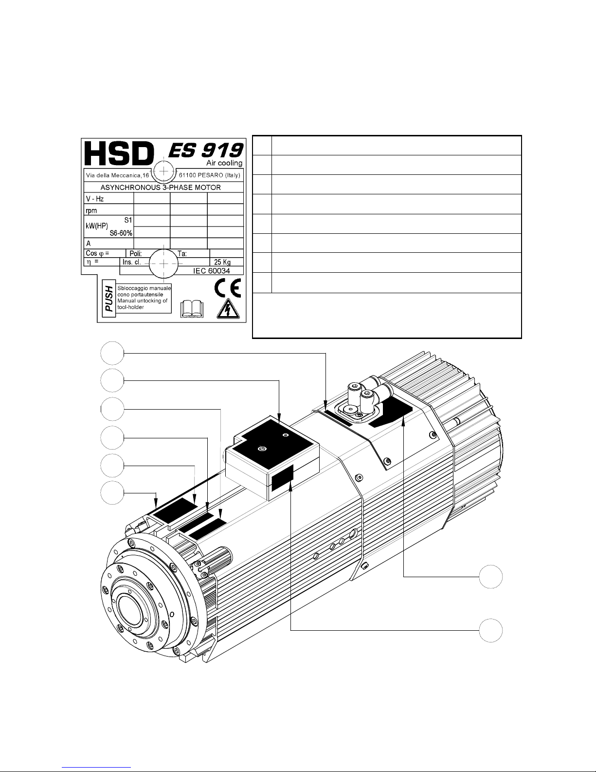
6.2 IDENTIFICATION OF MANUFACTURER AND PART
The data label shown below is the only form of electro-spindle identification recognised by the
manufacturer, and must be kept in its original legible condition. Figure 6.1 shows the electrospindle data label, while Figure 6.2 shows its location on the electro-spindle (Position 2).
1
Commercial part name and HSD code
2
CE label
3
“CERAMIC” (models with ceramic bearings only)
4
Serial number
5
Description of the tool holder cone
6
Commercial name of electro-spindle
7
Description of air inlets
8
HSD code for stator group
Figure 6.1 The CE label
NOTE:
Some of the symbols shown here may not be
present on your particular electro-spindle.
6
5
4
3
7
8
2
1
Figure 6.2 Location of the CE label and other symbols on the electro-spindle
______HSD Technological equipment for Automation _____________________________________
5801H0017 Rev. 02 _________________________________________________________ 11/98
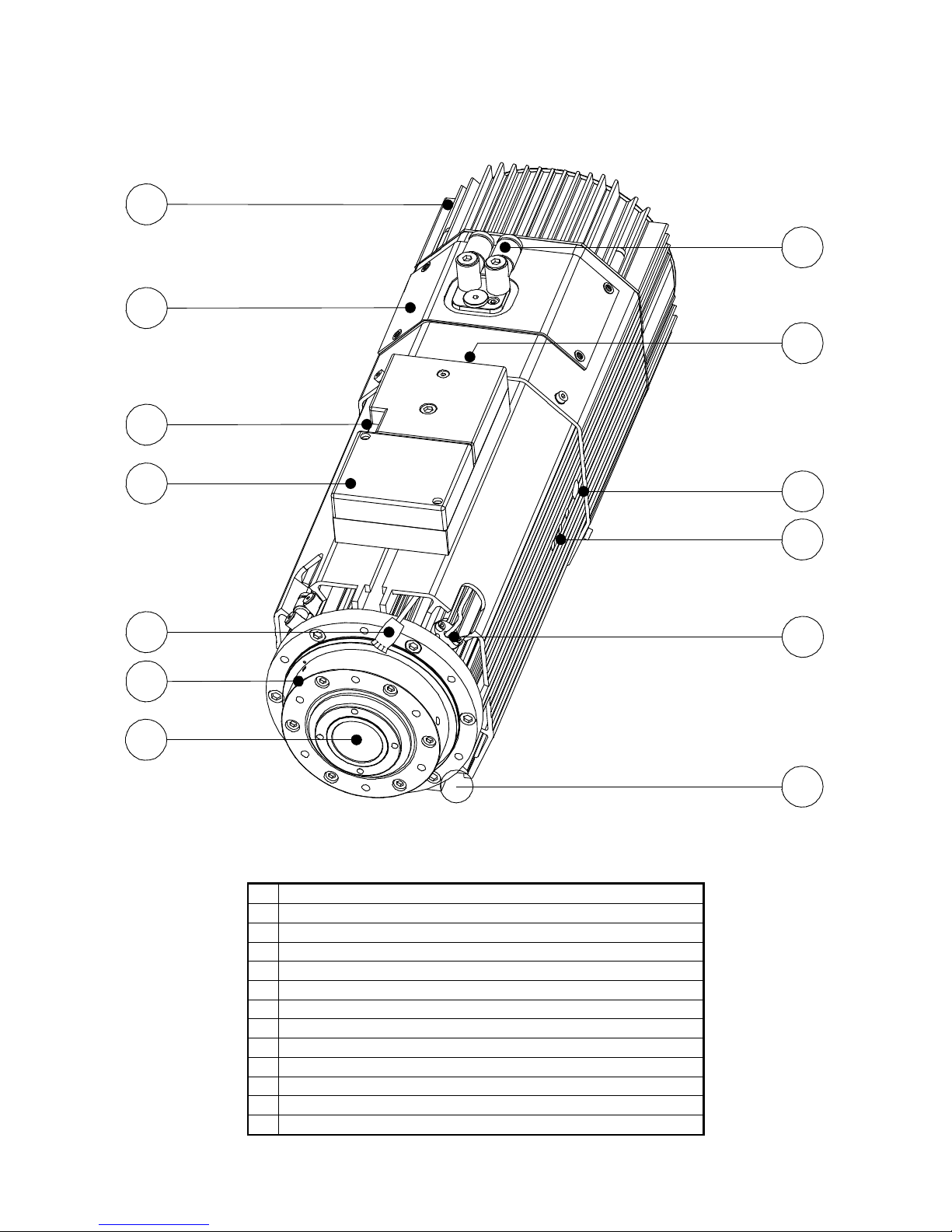
6.3 DESCRIPTION OF THE MAIN PARTS OF THE ELECTRO-SPINDLE
1
2
3
4
5
6
7
8
10
11
12
13
9
Figure 6.3 General view of the electro-spindle
1
Cooling fan
2
Sensor compartment
3
Manual tool holder release button
4
Configurable terminal block (optional)
5
C axis sensor connector (optional C axis)
6
Spindle nose
7
Spindle shaft
8
Compressed air connectors
9
Electrical terminals
10
Exhaust air silencer (one on each side)
11
Threaded service holes (see section 9.3.4 )
12
Temperature sensor for front bearings (optional)
13
“T” slots for anchoring to support
______HSD Technological equipment for Automation _____________________________________
5801H0017 Rev. 02 _________________________________________________________ 12/98
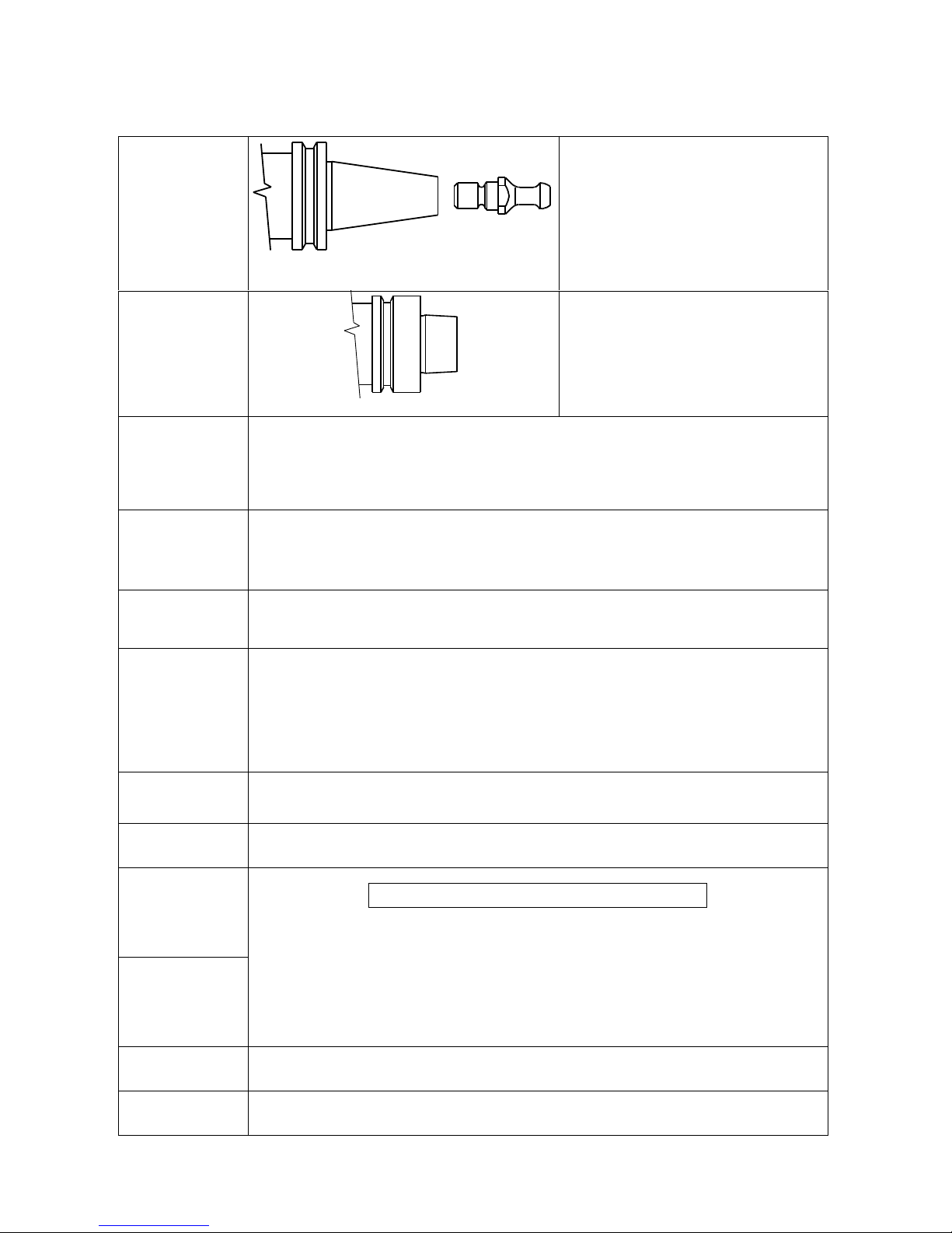
6.4 GLOSSARY
ISO 30
ISO30, DIN69871 CONE
HSD PULL STUD
0804H0009
The locking system for the tool holder
cone complies with DIN standard 69871.
The electro-spindle has a label showing
the type of tool holder mechanism (ISO
or HSK), bearing a symbol like that
shown at left.
HSK
DIN69893 HSK F63 CONE
The locking system for the tool holder
cone complies with DIN standard 69893.
The electro-spindle has a label showing
the type of tool holder mechanism (ISO
or HSK), bearing a symbol like that
shown at left.
Dynamic
balancing
class
The degree of balancing of a rotating object according to ISO standard 1940/1, defined
as the G rating.
Low G values mean better balancing. G = 0.4 specifies maximum balancing precision.
G assumes discrete values that increment in multiples of 2.5 (G=0.4 , G=1 , G=2.5 ,
etc.).
Scheduled
maintenance
Actions required to maintain the electro-spindle in the original condition, as specified by
HSD S.p.a..
Maintenance can include scheduled adjustments, repairs and part replacements.
Duty type S1
Functioning at constant load for enough time to bring the electro-spindle to a state of
thermal equilibrium.
Abbreviated as S1.
Duty type S6
A sequence of identical operating cycles, each comprising a period of functioning at
constant load and a period of functioning at no load but at the same rotation speed,
without any intermediate rest times.
Abbreviated as S6 followed by the percentage ratio between the period of functioning
under load and the duration of the cycle.
Example: S6 40%.
(40% functioning under load, 60% no load rotation).
Rated voltage
The maximum voltage permissible for electrical power to the electro-spindle.
Rated
frequency
The minimum frequency at which power at rated voltage must be delivered.
Torque
Power
..Torque (Nm) = [ 60 · power (W) ] : [ 2 · Π · rpm]..
Precise definition of torque and power goes beyond the scope of this manual.
Nevertheless, torque can be adequately understood as being related to the force with
which the tool bites into the work piece. (For the same torque, force increases as tool
diameter decreases.) Power on the other hand is proportional to torque and rotation
speed. Power limits the maximum machining speed (within the limits dictated by tool
performance, the characteristics of the material being machined, and the type of
machining involved).
Ratings
The set of rated values declared at rated frequency.
Coolants
Liquids or gases (including air), used as the medium for transferring heat from the
spindle into the environment.
______HSD Technological equipment for Automation _____________________________________
5801H0017 Rev. 02 _________________________________________________________ 13/98
§ 7 TECHNICAL SPECIFICATIONS
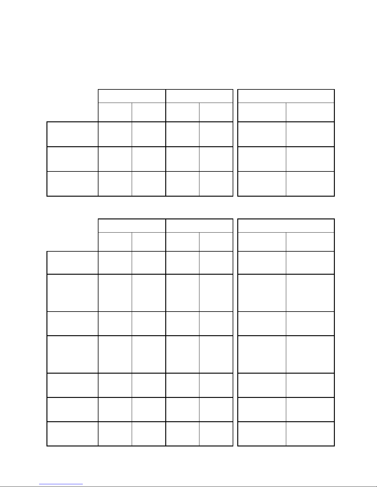
7.1 AVAILABLE MODELS
7.1.1 ES915 / ES915 L
ISO 30 HSK F63 RATED VOLTAGE
SHORT
NOSE
LONG
NOSE
SHORT
NOSE
LONG
NOSE
380 V
CONFIGURABLE
380 V / 220 V
3.8 kW
2 poles
air cooling
¦ ¦ ¦
5 kW
4 poles
air cooling
¦ ¦
7.5 kW
4 poles
liquid cooling
¦ ¦
7.1.2 ES919 / ES919 L
ISO 30 HSK F63 RATED VOLTAGE
SHORT
NOSE
LONG
NOSE
SHORT
NOSE
LONG
NOSE
380 V
CONFIGURABLE
380 V / 220 V
7 kW
2 poles
air cooling
¦ ¦ ¦ ¦
7 kW
2 poles
air cooling
whith belt-driven
"C Axis" unit
¦ ¦ ¦
8 kW
2 poles
air cooling
¦ ¦ ¦ ¦
8 kW
2 poles
air cooling
whith belt-driven
"C Axis" unit
¦ ¦ ¦
5.5 kW
4 poles
air cooling
¦ ¦ ¦
7.5 kW
4 poles
air cooling
¦ ¦ ¦ ¦ ¦
12 kW
4 poles
liquid cooling
¦ ¦ ¦ ¦ ¦
______HSD Technological equipment for Automation _____________________________________
5801H0017 Rev. 02 _________________________________________________________ 14/98
7.2 TECHNICAL SPECIFICATIONS OF ES915
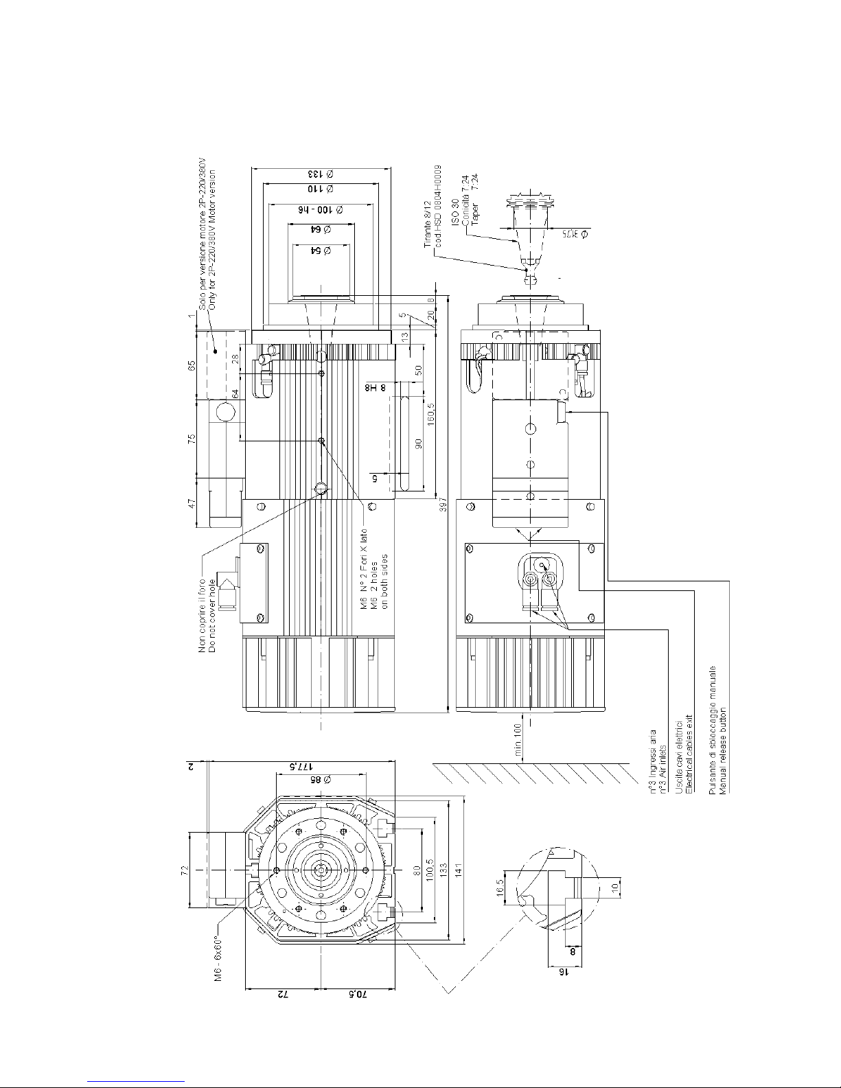
7.2.1 Overall dimensions of ES915
______HSD Technological equipment for Automation _____________________________________
5801H0017 Rev. 02 _________________________________________________________ 15/98
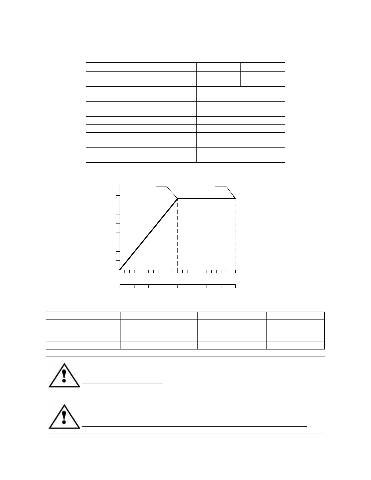
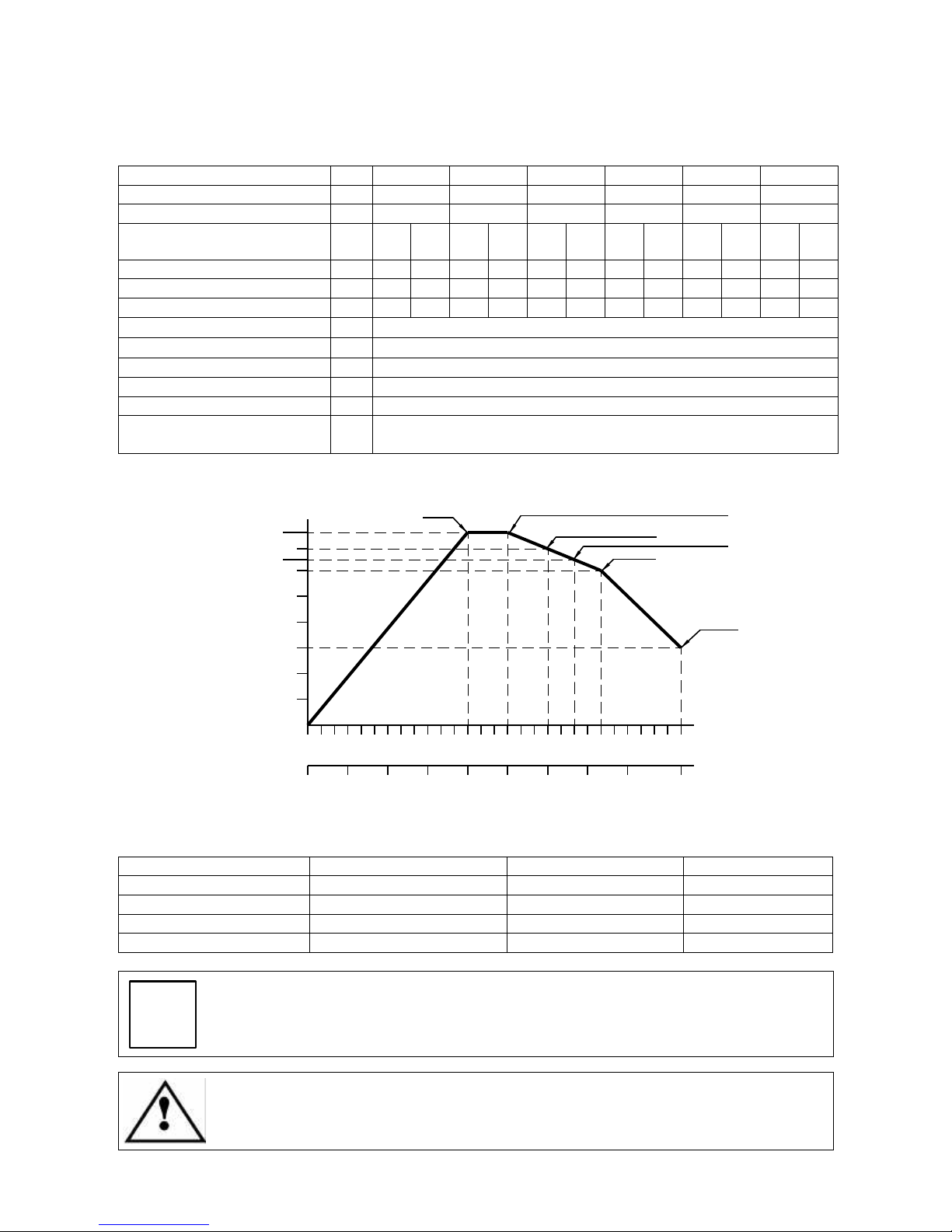
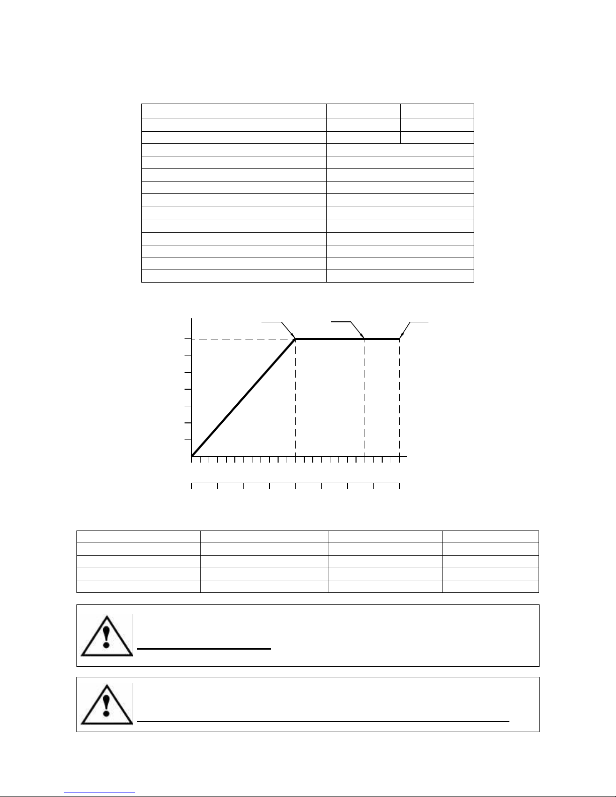
7.2.2 Specifications and performance of ES915 2 Pole, 3.8 kW units
Terminal connection type
Star Delta
Rated voltage (*)
380 V ± 10% 220 V ± 10%
Rated current
8.3 A 14.4 A
Rated speed
12000 rpm (200 Hz)
Rated power
3.8 kW
Duty type
S1
Rated torque
3 Nm
Rated efficiency η
0.8
Power factor cos ϕ
0.8
Number of poles
2
Insulation class
H
Type of cooling
Cooling fan
Weight
~ 21 kg
[(*) from inverter]
kW (S1)
Hz
0
3 6 9 12 15 18 21 2 4
1
2
3
4
0
50
100
150
200
250
300
350
400
3,8
3 Nm1,5 N
m
rpm x 1000
Notes:
TOOL HOLDER FRONT BEARINGS REAR BEARINGS MAX SPEED
ISO30 STEEL STEEL 20000rpm / 333Hz
ISO30 CERAMIC STEEL 24000rpm / 400Hz
ISO30 CERAMIC CERAMIC 24000rpm / 400Hz
ISO30 CRONIDUR / CHROMEX CERAMIC 28000rpm / 467Hz
The 3.8 kW 2 Pole motor is also available in a configurable double voltage
version.
Configurable models only: Check that the power terminals are correctly wired
for the supply voltage before installing the unit.
The maximum continuous current inverter parameter must match the rated
current value in the table above (also stated on the motor’s data label).
Select the right value depending on whether the connection is star or delta.
______HSD Technological equipment for Automation _____________________________________
5801H0017 Rev. 02 _________________________________________________________ 16/98
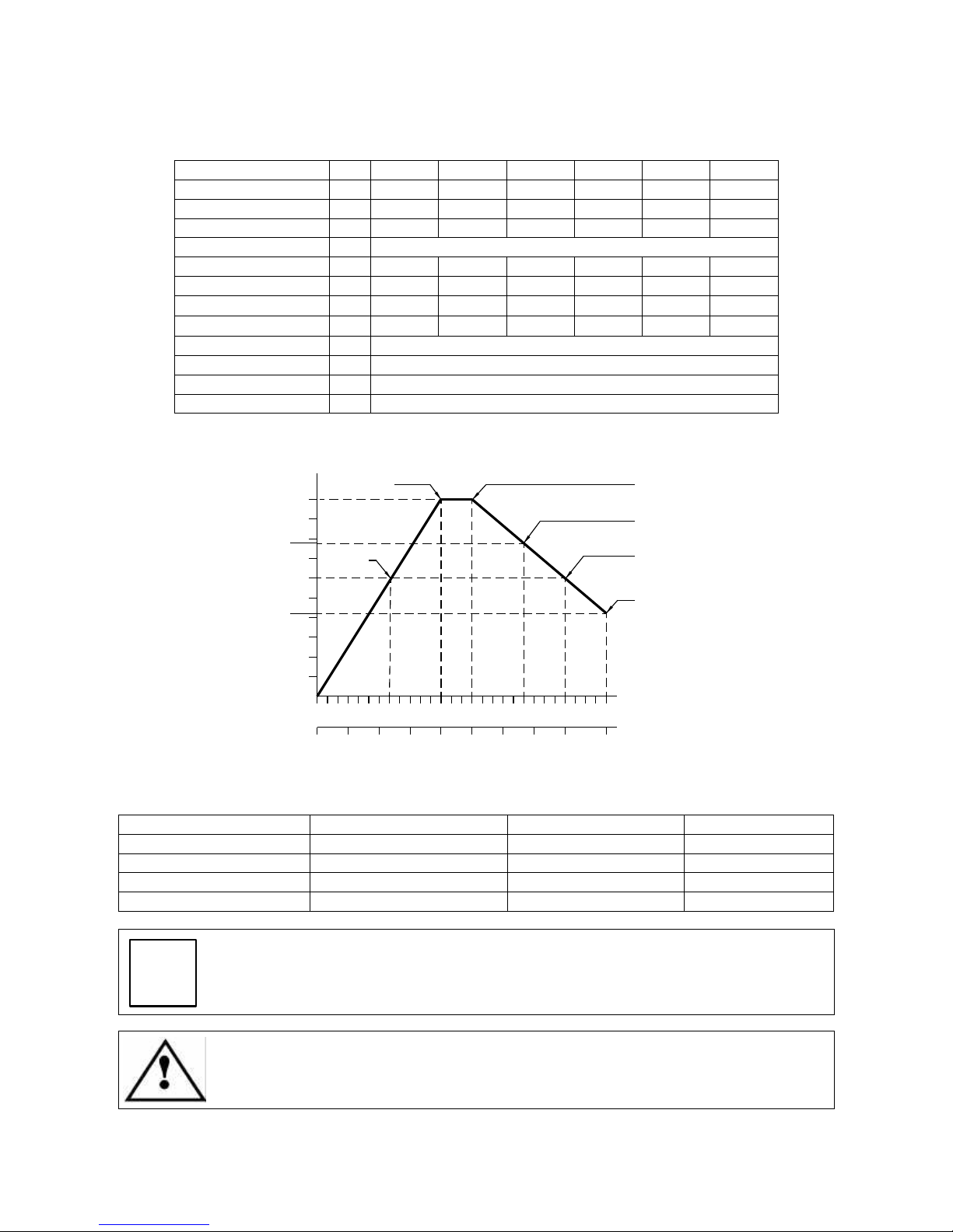
7.2.3 Specifications and performance of ES915 4 Pole, 5 kW units
Rated voltage (*)
V 225 ±10% 380 ±10% 380 ±10% 380 ±10% 380 ±10% 380 ±10%
Rated frequency
Hz 233 400 500 667 800 933
Rated speed
rpm 7000 12000 15000 20000 24000 28000
Rated power
kW 3 5 5 3.9 3 2,1
Duty type
S1
Rated torque
Nm 4 4 3.2 1.7 1.2 0.7
Rated current
A 12 12 10,5 9.2 7 4
Rated efficiency η
0.8 0.8 0.8 0.8 0.8 0.8
Power factor cos ϕ
0.85 0.85 0.85 0.8 0.8 0.75
Number of poles
4
Insulation class
F
Type of cooling
Cooling fan
Weight
kg ~ 21
[(*) from inverter]
kW (S1)
Hz
0
rpm x 1000
3 6 9 12 15 18 21 24 28
2,1
3,9
5
0
100
200
300
400
500
600
700
933
4
1
3
4 Nm
4 Nm
3,2 Nm
1,7 Nm
0,7 Nm
800
1,2 Nm
2
Notes:
TOOL HOLDER FRONT BEARINGS REAR BEARINGS MAX SPEED
ISO30 STEEL STEEL 20000rpm / 667Hz
ISO30 CERAMIC STEEL 24000rpm / 800Hz
ISO30 CERAMIC CERAMIC 24000rpm / 800Hz
ISO30 CRONIDUR / CHROMEX CERAMIC 28000rpm / 933Hz
i
The 5 kW, 4 Pole motor is not available with configurable double voltage power
terminals.
The maximum continuous current inverter parameter must match the maximum
value of the rated current in the table above (also stated on the motor’s data
label).
______HSD Technological equipment for Automation _____________________________________
5801H0017 Rev. 02 _________________________________________________________ 17/98
7.3 TECHNICAL SPECIFICATIONS OF ES915 L
7.3.1 Overall dimensions of ES915 L HSK F63 Long Nose
______HSD Technological equipment for Automation _____________________________________
5801H0017 Rev. 02 _________________________________________________________ 18/98
7.3.2 Specifications and performance of ES915 L 4 Pole, 7.5 kW units
Rated voltage (*)
V
380 ±10% 380 ±10% 380 ±10% 380 ±10% 380 ±10% 380 ±10%
Rated frequency
Hz 400 500 600 667 733 933
Rated speed
rpm 12000 15000 18000 20000 22000 28000
Duty type
S1
contS650%S1contS650%S1contS650%S1contS650%S1contS650%S1contS650%
Rated power
kW
6,5 7,5 6,5 7,5 6,1 6,7 5,8 6,4 5,5 6 3 3
Rated torque
Nm 5,2 6 4,1 4,8 3,2 3,6 2,8 3,1 2,4 2,6 1 1
Rated current
A
15 18 15 18 14 15,7 13 16 13,1 14,1 7,5 7,5
Rated efficiency η
0,82
Power factor cos ϕ
0,74
Number of poles
4
Insulation class
F
Type of cooling
Liquid cooling
Weight of
LONG NOSE variant
kg ~ 29
[(*) from inverter]
kW (S6 50%)
Hz
0
rpm x 1000
3 6 9 12 15 18 21 24 28
1
2
3
4
5
6
6,7
0
100
200
300
400
500
600
700
933
7,5
6 Nm
4,8 N
m
3,6 Nm
800
2,6 Nm
1 Nm
6,4
3,1 N
m
Note:
TOOL HOLDER FRONT BEARINGS REAR BEARINGS MAX SPEED
HSK F63 STEEL STEEL 18000rpm / 600Hz
HSK F63 CERAMIC STEEL 20000rpm / 667Hz
HSK F63 CERAMIC CERAMIC 22000rpm / 733Hz
HSK F63 CRONIDUR / CHROMEX CERAMIC 28000rpm / 933Hz
i
The 7.5 kW, 4 Pole motor is not available with configurable double voltage
power terminals.
The maximum continuous current inverter parameter must match the maximum
value of the rated current in the table above (also stated on the motor’s data
label).
______HSD Technological equipment for Automation _____________________________________
5801H0017 Rev. 02 _________________________________________________________ 19/98
7.4 TECHNICAL SPECIFICATIONS OF ES919
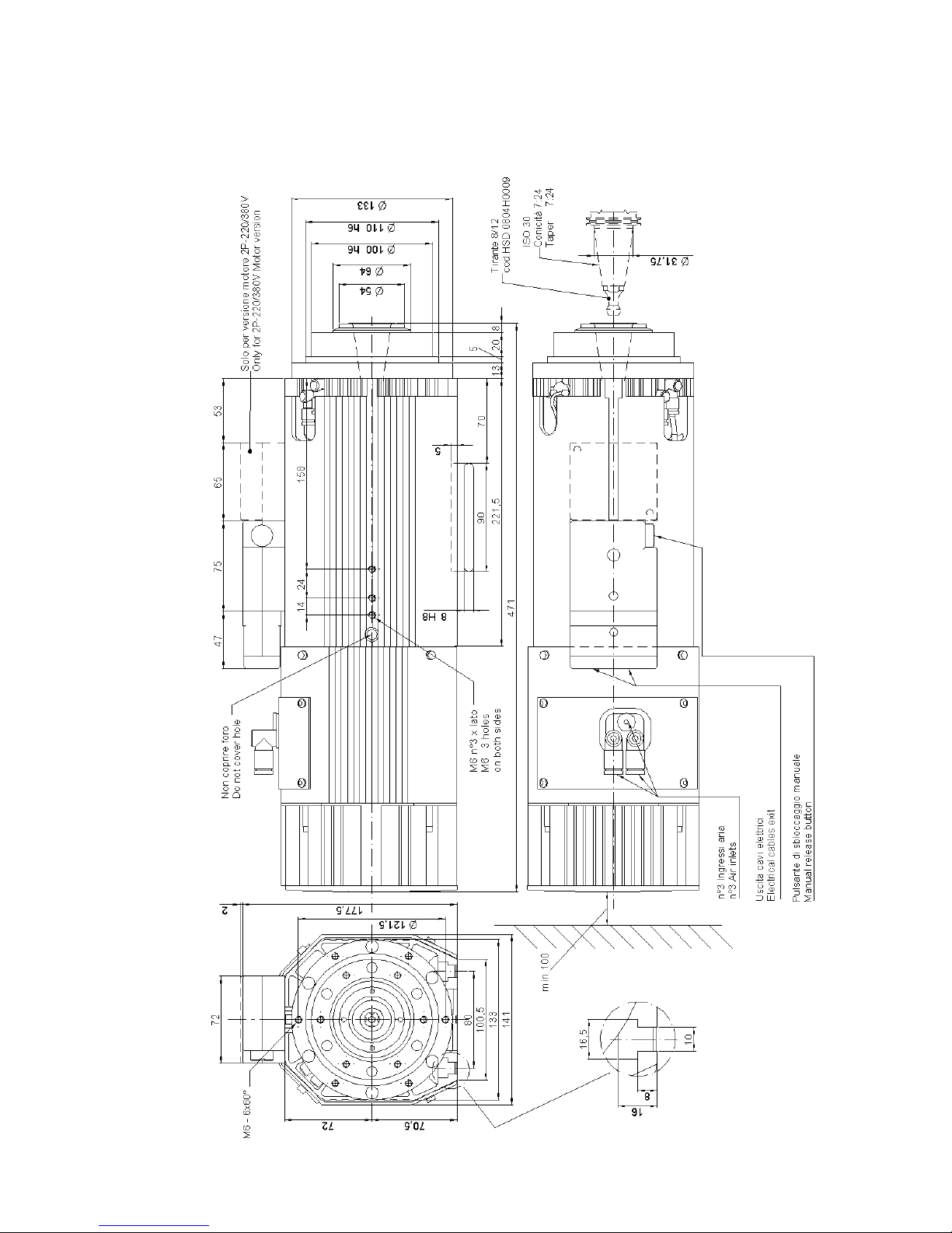
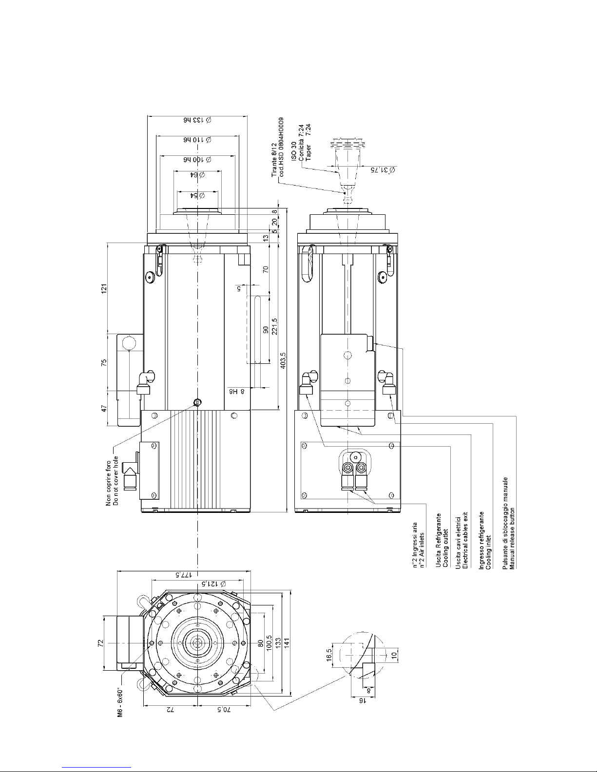
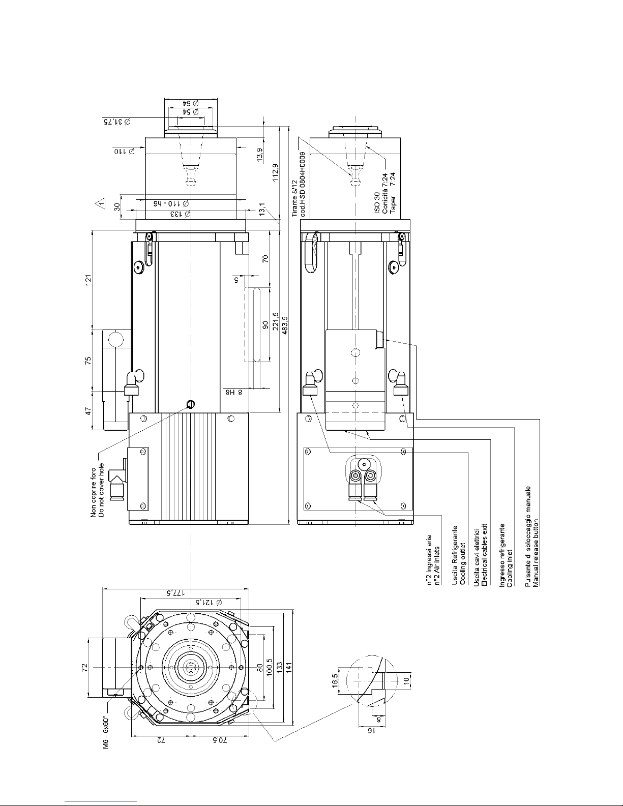
7.4.1 Overall dimensions of ES919 ISO30 Short Nose
______HSD Technological equipment for Automation _____________________________________
5801H0017 Rev. 02 _________________________________________________________ 20/98
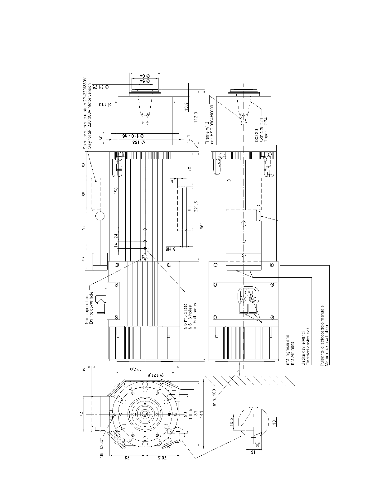
7.4.2 Overall dimensions of ES919 ISO30 Long Nose

______HSD Technological equipment for Automation _____________________________________
5801H0017 Rev. 02 _________________________________________________________ 21/98
7.4.3 Overall dimensions of ES919 HSK F63 Short Nose
______HSD Technological equipment for Automation _____________________________________
5801H0017 Rev. 02 _________________________________________________________ 22/98
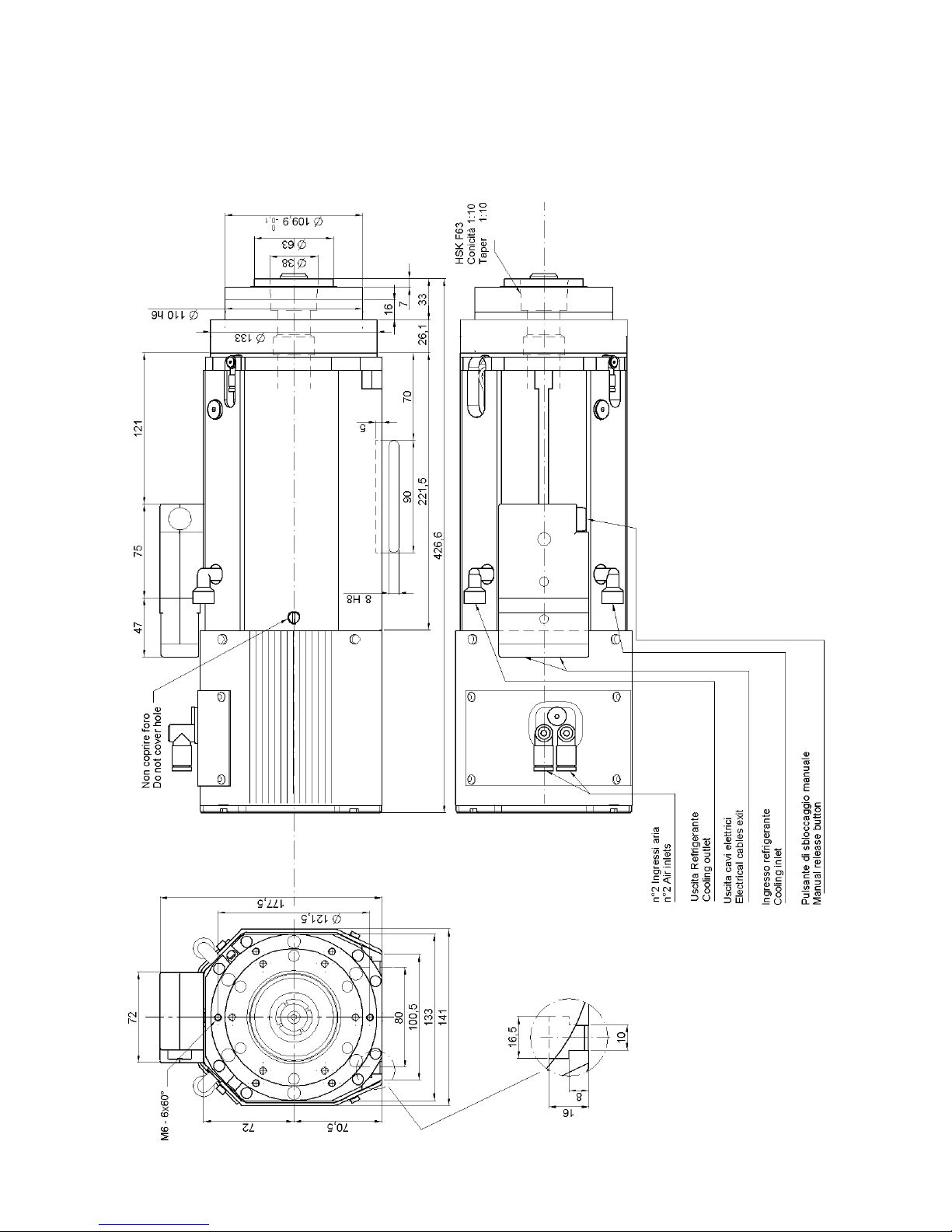
7.4.4 Overall dimensions of ES919 HSK F63 Long Nose
______HSD Technological equipment for Automation _____________________________________
5801H0017 Rev. 02 _________________________________________________________ 23/98
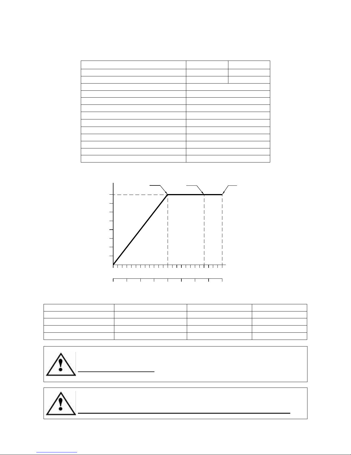
7.4.5 Specifications and performance of ES919 2 Pole, 7 kW units
Terminal connection type
Star Delta
Rated voltage (*)
380 V ± 10% 220 V ± 10%
Rated current
16 A 28 A
Rated speed
12000 rpm (200 Hz)
Rated power
7 kW
Duty type
S1
Rated torque
5.6 Nm
Rated efficiency η
0.8
Power factor cos ϕ
0.8
Number of poles
2
Insulation class
H
Type of cooling
Cooling fan
Weight of SHORT NOSE variant
~ 26 kg
Weight of LONG NOSE variant
~ 31 kg
[(*) from inverter]
kW (S1)
Hz
0
rpm x 1000
3 6 9 1 2 15 18 21 2 4
1
2
3
4
5
6
7
0
50
100
150
200
250
300
350
400
5,6 Nm3,3 Nm2,8 N
m
Notes:
TOOL HOLDER FRONT BEARINGS REAR BEARINGS MAX SPEED
ISO30 STEEL STEEL 20000rpm / 333Hz
ISO30 CERAMIC STEEL 24000rpm / 400Hz
ISO30 CERAMIC CERAMIC 24000rpm / 400Hz
ISO30 CRONIDUR / CHROMEX CERAMIC 28000rpm / 467Hz
The 7 kW 2 Pole motor is also available in a configurable double voltage
version.
Configurable models only: Check that the power terminals are correctly wired
for the supply voltage before installing the unit.
The maximum continuous current inverter parameter must match the rated
current value in the table above (also stated on the motor’s data label).
Select the right value depending on whether the connection is star or delta.
______HSD Technological equipment for Automation _____________________________________
5801H0017 Rev. 02 _________________________________________________________ 24/98
7.4.6 Specifications and performance of ES919 2 Pole, 8 kW units
Terminal connection type
Star Delta
Rated voltage (*)
380 V ± 10% 220 V ± 10%
Rated current
18 A 32 A
Rated speed
12000 rpm (200 Hz)
Rated power
8 kW
Duty type
S1
Rated torque
6.4 Nm
Rated efficiency η
0.8
Power factor cos ϕ
0.8
Number of poles
2
Insulation class
H
Type of cooling
Cooling fan
Weight of SHORT NOSE variant
~ 26 kg
Weight of LONG NOSE variant
~ 31 kg
[(*) from inverter]
kW (S1)
Hz
0
rpm x 1000
3 6 9 12 15 18 21 24
1
2
3
4
5
6
7
8
0
50
100
150
200
250
300
350
400
6,4 N
m
3,6 Nm 3,2 Nm
Notes:
TOOL HOLDER FRONT BEARINGS REAR BEARINGS MAX SPEED
ISO30 STEEL STEEL 20000rpm / 333Hz
ISO30 CERAMIC STEEL 24000rpm / 400Hz
ISO30 CERAMIC CERAMIC 24000rpm / 400Hz
ISO30 CRONIDUR / CHROMEX CERAMIC 28000rpm / 467Hz
The 8 kW 2 Pole motor is also available in a configurable double voltage
version.
Configurable models only: Check that the power terminals are correctly wired
for the supply voltage before installing the unit.
The maximum continuous current inverter parameter must match the rated
current value in the table above (also stated on the motor’s data label).
Select the right value depending on whether the connection is star or delta.

______HSD Technological equipment for Automation _____________________________________
5801H0017 Rev. 02 _________________________________________________________ 25/98
7.4.7 Specifications and performance of ES919 4 Pole, 5.5 kW units
Rated voltage (*)
380 V ± 10% 380 V ± 10% 380 V ± 10%
Rated frequency
233 Hz 400 Hz Hz 600
Rated speed
7000 rpm 12000 rpm 18000 rpm
Rated power
5.5 kW 4.5 kW 1.5 kW
Duty type
S1
Rated torque
7.5 Nm 3.6 Nm 0.8 Nm
Rated current
15 A 14 A 6.5 A
Rated efficiency η
0,8
Power factor cos ϕ
0,8
Number of poles
4
Insulation class
H
Type of cooling
Cooling fan
Weight
~ 26 kg
[(*) from inverter]
kW (S1)
Hz
0
rpm x 1000
3 6 9 12 15 18
1
2
3
4
5
0
100
200
300
400
500
600
5,5
4,5
1,5
7,5 N
m
3,6 Nm
0,8 Nm
Notes:
TOOL HOLDER FRONT BEARINGS REAR BEARINGS MAX SPEED
ISO30 STEEL STEEL 18000rpm / 600Hz
ISO30 CERAMIC STEEL 18000rpm / 600Hz
i
The 5.5 kW, 4 Pole motor is not available with configurable double voltage
power terminals.
The maximum continuous current inverter parameter must match the maximum
value of the rated current in the table above (also stated on the motor’s data
label).
______HSD Technological equipment for Automation _____________________________________
5801H0017 Rev. 02 _________________________________________________________ 26/98
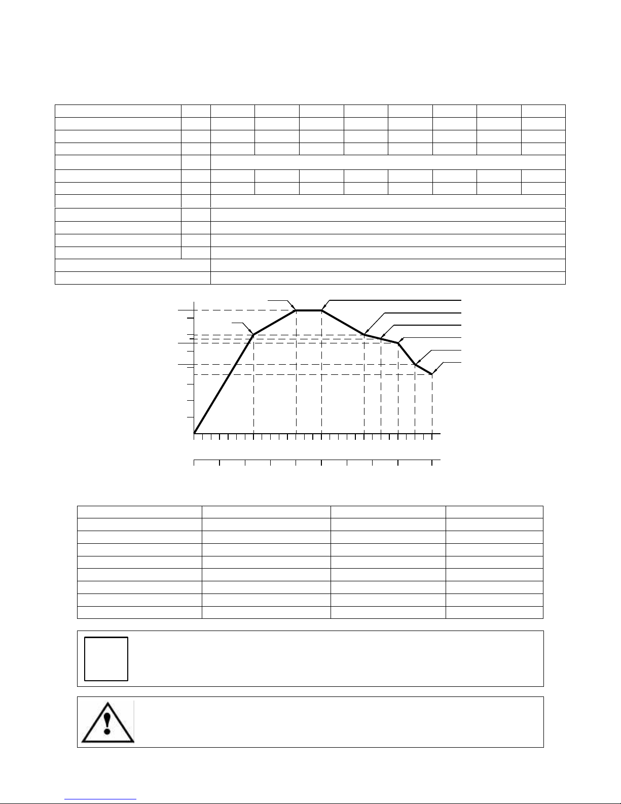
7.4.8 Specifications and performance of ES919 4 Pole, 7.5 kW units
Rated voltage (*)
V 225 ± 10% 380 ± 10% 380 ± 10% 380 ± 10% 380 ± 10% 380 ± 10% 380 ± 10% 380 ± 10%
Rated frequency
Hz 233 400 500 667 733 800 867 933
Rated speed
rpm 7000 12000 15000 20000 22000 24000 26000 28000
Rated power
kW 6 7.5 7.5 6 5.75 5.5 4.2 3.6
Duty type
S1
Rated torque
Nm 8.2 6 4.8 2.9 2.5 2.2 1.5 1.2
Rated current
A 25 20 17 15 13 13 10 11.5
Rated efficiency η
0,8
Power factor cos ϕ
0,8
Number of poles
4
Insulation class
F
Type of cooling
Cooling fan
Weight of SHORT NOSE variant
~ 26 kg
Weight of LONG NOSE variant
~ 31 kg
[(*) from inverter]
kW (S1)
Hz
0
rpm x 1000
3 6 9 12 15 18 21 24 28
1
2
3
4
5
6
7
0
100
200
300
400
500
600
700
933
4,2
7,5
8,2 Nm
6 Nm4,8 N
m
2,9 Nm
2,2 Nm
800
5,5
1,5 Nm
5,5
2,5 Nm
1,2 Nm
Notes:
TOOL HOLDER FRONT BEARINGS REAR BEARINGS MAX SPEED
HSK F63 STEEL STEEL 18000rpm / 600Hz
HSK F63 CERAMIC STEEL 20000rpm / 667Hz
HSK F63 CERAMIC CERAMIC 22000rpm / 733Hz
HSK F63 CRONIDUR / CHROMEX CERAMIC 26000rpm / 867Hz
ISO30 STEEL STEEL 20000rpm / 667Hz
ISO30 CERAMIC STEEL 24000rpm / 800Hz
ISO30 CERAMIC CERAMIC 24000rpm / 800Hz
ISO30 CRONIDUR / CHROMEX CERAMIC 28000rpm / 933Hz
i
The 7.5 kW, 4 Pole motor is not available with configurable double voltage
power terminals.
The maximum continuous current inverter parameter must match the maximum
value of the rated current in the table above (also stated on the motor’s data
label).
______HSD Technological equipment for Automation _____________________________________
5801H0017 Rev. 02 _________________________________________________________ 27/98
7.5 TECHNICAL SPECIFICATIONS OF ES919 L
7.5.1 Overall dimensions of ES919 L ISO30 Short Nose
______HSD Technological equipment for Automation _____________________________________
5801H0017 Rev. 02 _________________________________________________________ 28/98
7.5.2 Overall dimensions of ES919 L ISO30 Long Nose
______HSD Technological equipment for Automation _____________________________________
5801H0017 Rev. 02 _________________________________________________________ 29/98
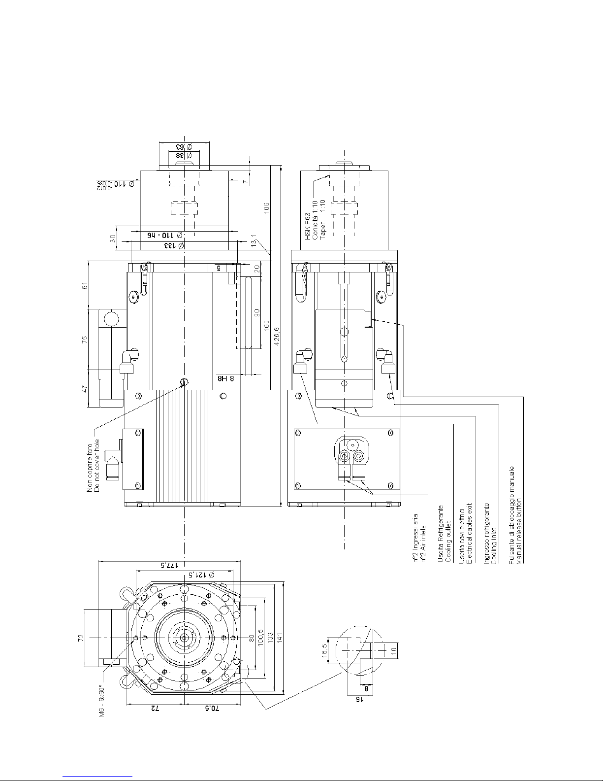
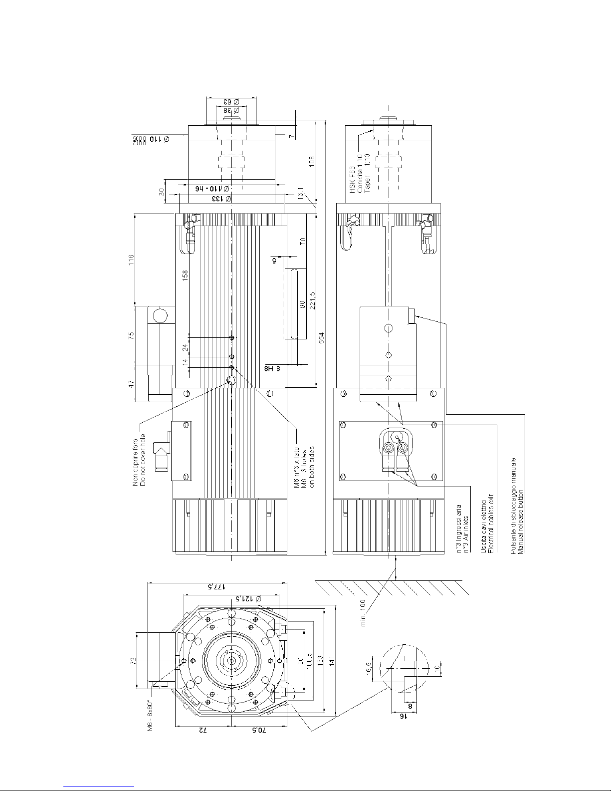
7.5.3 Overall dimensions of ES919 L HSK F63 Short Nose
______HSD Technological equipment for Automation _____________________________________
5801H0017 Rev. 02 _________________________________________________________ 30/98
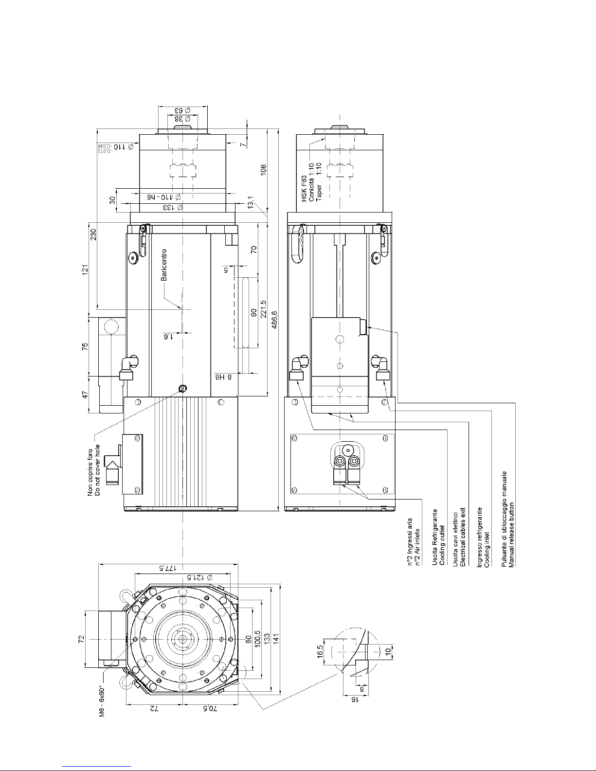
7.5.4 Overall dimensions of ES919 L HSK F63 Long Nose
 Loading...