

Page 1
HSD
MECHATRONIC
DIVISION
Instructions for use
ES884 – ES888
5801H0056
Rev.02
EN
ES915
ES919 – ES929 – ES939
ES983 – ES988
5801H0056 Rev.02 __________________________________________________________ 1/181
Page 2

HSD
Information about the document
ISSUED BY CODE REVISION APPROVAL
HSD S.p.A.
Via della Meccanica 16
Loc. Chiusa di Ginestreto
5801H0056
61100 PESARO (ITALIA)
List of updates
Revision Modified paragraph Description of the modification
00 (12.02.2007) First issue First issue
01 (06.03.2007)
02 (02.06.2008)
§12.7
§12.7.2
General
§ 5.2
§ 6.2
§ 6.4
§ 9
§ 10.3
§ 10.4
§ 10.6
§ 10.8.5
§ 13.2.2
§ 13.2.2.9
§ 15
Elimination of the note “respect the number of rotations ...”; elimination of the phrase “on the basis of the type and
quality ...” (both the eliminated parts are already present in paragraph §12.7.1).
Additional explanation of the simplified calculation for the centre of gravity.
Added ES884, ES888, ES915, ES919, ES939, ES983, ES988 models
Symbols updated
Wording on shaft kits corrected
Glossary: generalised wording “ISO” and “HSK”
Motor identification plates and equivalent electrical networks of all motors added
Fixing specifications added
Pressurisation values added
Electrical connections of encoder models and with military connectors added
Note on possible tie-rod breakage added
Sensor connections and positions updated
Sensor adjustment procedure for HSK E63 models added
List of spare parts and note on shaft kit updated
This manual has been drawn up by the Electrospindles Technical Office of HSD S.p.A. and is to be
used by all installers, users and maintenance engineers working with the electrospindle.
This manual is supplied together with the product; it is the most updated documentation available
at the revision date.
For the updates, visit the website www.HSD.it
or contact HSD Customer Service.
The manual must be kept in a suitable place that is easily accessed and known to the personnel
using the product. In addition, it must be kept carefully for the entire lifespan of the product, and
must accompany the product if this is ceded to third parties.
This publication is the English translation of the original Italian version of the manual HSD.
In case of discrepancies between this translation and the original version, refer to the original
version in Italian.
02
UTE 002 / 07
5801H0056 ________________________________________________________________ 2/181
Page 3

HSD
TABLE OF CONTENTS
1 PRELIMINARY INFORMATION ....................................................................................6
1.1 DOCUMENTS SUPPLIED WITH THE ELECTROSPINDLE ............................................. 6
1.2 PURPOSE OF THE MANUAL .......................................................................................... 6
1.3 GENERAL SAFETY SYMBOLS ....................................................................................... 6
1.4 RISKS ASSOCIATED WITH THE USE OF THE ELECTROSPINDLE.............................. 7
1.5 RISKS ASSOCIATED WITH INCORRECT USE AND/OR OPERATION.......................... 7
1.6 SPECIFIC RISKS DURING ELECTROSPINDLE MAINTENANCE................................... 8
1.7 RESIDUAL RISKS............................................................................................................ 8
1.8 PURPOSE OF THE PRODUCT ........................................................................................ 8
1.9 RANGE OF APPLICATIONS............................................................................................ 8
1.10 IDENTIFICATION OF THE PRODUCT AND THE MANUFACTURER.............................. 8
1.11 GLOSSARY...................................................................................................................... 9
1.12 GUARANTEE CONDITIONS .......................................................................................... 10
2 TECHNICAL SPECIFICATIONS..................................................................................11
2.1 MAIN PARTS OF ES915/ES919/ES929/ES988.............................................................. 11
2.2 MAIN PARTS OF MODELS ES884 - ES888................................................................... 12
2.3 MAIN PARTS OF MODEL ES939................................................................................... 13
2.4 VARIATIONS WITH VERTICAL MOUNTING PLATE..................................................... 14
2.5 VARIATIONS WITH MILITARY CONNECTORS ............................................................ 15
2.6 TECHNICAL CARDS ES884 .......................................................................................... 16
2.7 TECHNICAL CARDS ES888 .......................................................................................... 18
2.8 TECHNICAL CARDS ES915 .......................................................................................... 20
2.9 TECHNICAL CARDS ES919 .......................................................................................... 26
2.10 TECHNICAL CARDS ES929 .......................................................................................... 40
2.11 TECHNICAL CARDS ES939 .......................................................................................... 44
2.12 TECHNICAL CARDS ES983 .......................................................................................... 52
3 TRANSPORT, PACKAGING, UNPACKING, STORAGE............................................65
3.1 WARNINGS.................................................................................................................... 65
3.2 DIMENSIONS AND WEIGHTS ....................................................................................... 65
3.3 TRANSPORT AND PACKAGING CONDITIONS ........................................................... 65
3.4 UNPACKING PROCEDURE........................................................................................... 65
3.5 STORAGE ...................................................................................................................... 66
4 INSTALLATION AND INITIAL START-UP..................................................................67
4.1 CHECK ...........................................................................................................................67
4.2 PREPARATION OF THE AUXILIARY SYSTEMS OF THE PLANT................................ 67
4.3 MECHANICAL CONNECTIONS..................................................................................... 67
4.3.1 Positioning of electrospindle (versions with electric fan)............................................. 67
4.3.2 Electrospindle resting surface (versions with rectangular framework) ........................ 68
4.3.3 Fixing structure for spindles with round framework .................................................... 68
4.3.4 Tool change system................................................................................................... 69
4.3.5 Fixing electrospindles with rectangular framework..................................................... 70
4.3.6 Fixing electrospindles with round framework.............................................................. 70
4.3.7 Threaded bores for accessories................................................................................. 70
4.4 PNEUMATIC CONNECTIONS........................................................................................ 71
4.4.1 Air purity .................................................................................................................... 71
4.4.2 Pneumatic connection points for spindles with single-acting cylinder......................... 72
4.4.3 Variation with vertical block (single-acting cylinder) ................................................... 72
4.4.4 Pneumatic connection points ES939 or variations with “T-block” (double-acting
cylinder) ................................................................................................................................. 74
4.4.5 Pneumatic connection points for spindles ES884 - ES888 (single-acting cylinder)..... 76
4.4.6 Internal volumes of the pneumatic cylinders .............................................................. 78
4.4.7 Internal pressurisation ............................................................................................... 78
5801H0056 ________________________________________________________________ 3/181
Page 4

HSD
4.4.8 Cleaning the tool-holder cone.................................................................................... 78
4.5 HYDRAULIC CONNECTIONS AND SPECIFICATIONS OF THE COOLER................... 79
4.5.1 Specifications for the cooler....................................................................................... 79
4.6 ELECTRICAL CONNECTIONS ...................................................................................... 80
4.6.1 Connectors ................................................................................................................ 80
4.6.2 Military connectors..................................................................................................... 83
4.6.3 Configurable power supply terminal board 220/380 V (optional) ................................ 84
4.6.4 ES988 with configurable terminal board 220/440 V (optional).................................... 85
4.7 BUTTON FOR MANUAL COMMAND OF TOOL RELEASE .......................................... 86
4.7.1 Electrical layout for tool-holder manual release circuit ............................................... 86
5 GENERAL CHECKS AFTER INSTALLATION............................................................87
5.1 CHECKS BEFORE THE START-UP .............................................................................. 87
5.1.1 Positioning................................................................................................................. 87
5.1.2 Pneumatic connections.............................................................................................. 87
5.1.3 Electrical connections................................................................................................ 87
5.1.4 Programming the inverter .......................................................................................... 87
5.2 START-UP CHECKS...................................................................................................... 87
6 USE AND ADJUSTMENT............................................................................................88
6.1 ENVIRONMENTAL CONDITIONS.................................................................................. 88
6.2 RUNNING-IN................................................................................................................... 88
6.3 PREHEATING................................................................................................................. 88
6.4 ELECTRIC FAN.............................................................................................................. 88
6.4.1 Technical characteristics of the electric fan................................................................ 89
6.5 TOOL-HOLDER LOCKING AND EXPULSION DEVICE................................................. 89
6.6 TOOL-HOLDER CONE................................................................................................... 89
6.6.1 Installation of the tie-rod HSD 0804H0009 in the cone ISO30 DIN69871................... 90
6.6.2 General recommendations for the tool-holder cones.................................................. 90
6.7 TOOL.............................................................................................................................. 90
6.7.1 Speed limits............................................................................................................... 91
6.7.2 Maximum speed and shape of the tool ...................................................................... 91
6.8 WHAT TO DO IF THE TOOL IS BLOCKED ON THE PIECE BEING WORKED .......... 111
6.9 SENSORS .................................................................................................................... 113
6.9.1 Technical characteristics of the inductive sensors ................................................... 113
6.9.2 Status modes of the electrospindle and corresponding outputs ............................... 114
6.9.3 Output of sensor S3: “shaft idle” signal .................................................................... 114
6.9.4 Use and technical characteristics of the thermal alarm ............................................ 115
6.10 ENCODER (OPTIONAL)............................................................................................... 115
6.10.1 General description.................................................................................................. 115
6.10.2 Technical characteristics of the HSD Square Wave encoder ................................... 116
6.10.3 Output of the HSD Square Wave encoder ............................................................... 116
6.10.4 Technical characteristics of the Lenord+Bauer Square Wave encoder .................... 117
6.10.5 Output of the Lenord+Bauer Square Wave encoder ................................................ 117
6.10.6 Technical characteristics of the Lenord+Bauer sinusoidal encoder.......................... 118
7 MAINTENANCE.........................................................................................................124
7.1 SCHEDULED MAINTENANCE..................................................................................... 125
7.1.1 Checking the cleaning of the tool-holder cone and the conical housing in the spindle
shaft 125
7.1.2 Purging the filters of the pneumatic circuit ............................................................... 126
7.1.3 Protecting the conical seat in the spindle shaft ........................................................ 127
7.1.4 Cleaning the tool-holder cone.................................................................................. 127
7.1.5 Lubricating the HSK collet........................................................................................ 127
7.1.6 Checking the connections........................................................................................ 128
7.1.7 Replacing the filters of the pneumatic circuit............................................................ 128
7.1.8 Bearings .................................................................................................................. 128
5801H0056 ________________________________________________________________ 4/181
Page 5

HSD
8 REPLACING COMPONENTS....................................................................................129
8.1 REPLACING THE ELECTRIC FAN.............................................................................. 129
8.2 REPLACING THE SHAFT KIT FOR MODELS ES884, ES888..................................... 129
8.2.1 Disassembly procedure ........................................................................................... 129
8.2.2 Assembly procedure................................................................................................ 131
8.3 REPLACING THE SHAFT KIT FOR MODELS ES915,ES919,ES929,ES988............... 133
8.3.1 Disassembly procedure ........................................................................................... 133
8.3.2 Assembly procedure................................................................................................ 138
8.4 REPLACING THE SHAFT KIT FOR MODELS ES919 ENCODER............................... 142
8.4.1 Disassembly procedure ........................................................................................... 142
8.4.2 Assembly procedure................................................................................................ 145
8.5 REPLACING THE SHAFT KIT FOR MODELS ES939 ................................................. 148
8.6 REPLACING THE SHAFT KIT FOR MODELS ES939 WITH ENCODER..................... 149
8.6.1 Cylinder unit disassembly ........................................................................................ 149
8.6.2 Disassembly of shaft kit and phonic wheel............................................................... 151
8.7 REPLACING THE ENCODER READERS .................................................................... 154
8.7.1 Replacing the HSD optical encoder reader .............................................................. 154
8.8 REPLACING THE SENSORS....................................................................................... 158
8.8.1 Wiring the sensors of ISO30 models with single-acting piston ................................. 158
8.8.2 Wiring the sensors of HSK models with single-acting piston.................................... 158
8.8.3 Wiring the sensors of ISO30 models with double-acting piston................................ 159
8.8.4 Wiring the sensors of HSK models with double-acting piston................................... 159
8.8.5 Wiring the sensors of HSK models with boosted mounting plate.............................. 160
8.8.6 Accessing the sensors............................................................................................. 161
8.8.7 Position of the sensors ............................................................................................ 161
8.8.8 Accessing the ES939 sensors ................................................................................. 162
8.8.9 Position of the ES939 sensors................................................................................. 162
8.8.10 Position of the sensors in models ES884/ES888 ..................................................... 163
8.8.11 Description of the sensor unit .................................................................................. 163
8.8.12 Replacing the sensor unit ........................................................................................ 164
8.8.13 Adjusting sensor S1 (both ISO and HSK versions) .................................................. 165
8.8.14 Adjusting sensor S2 in ISO versions........................................................................ 166
8.8.15 Adjusting sensor S2 in HSK versions....................................................................... 167
8.8.16 Adjusting sensor S3 (both ISO and HSK versions) .................................................. 167
8.8.17 Adjusting sensor S4 (HSK versions only)................................................................. 168
8.8.18 Kit of gauges to adjust sensors S1 and S4 HSK F63 (code HSD 3811H0110)......... 169
8.8.19 Kit of gauges to adjust sensors S1 and S4 HSK E63 (code HSD 3811H0739) ........ 171
9 OPTIONAL PARTS....................................................................................................173
9.1 COOLING WITH FORCED AIR .................................................................................... 173
9.2 INSTALLATION OF THE KIT FOR COOLING WITH FORCED AIR ............................ 174
10 TROUBLESHOOTING...............................................................................................175
11 LIST OF SPARE PARTS ...........................................................................................179
12 DISPOSAL.................................................................................................................180
13 CUSTOMER SERVICE ..............................................................................................181
5801H0056 ________________________________________________________________ 5/181
Page 6
HSD
i
1 PRELIMINARY INFORMATION
1.1 DOCUMENTS SUPPLIED WITH THE ELECTROSPINDLE
The documentation supplied with the product consists of:
• the Manufacturer's Declaration in accordance with Appendix IIB of Directive 2006/42/EC
• the product inspection certificate.
• this manual, containing the warnings and instructions for transport, installation, operation,
1.2 PURPOSE OF THE MANUAL
• The manual is an integral part of the electrospindle and must compulsorily accompany it,
• The manual must be handled with care, distributed and made available to all persons
• The purpose of the warnings is to protect the safety of the persons exposed to residual risks.
maintenance and disposal of the product.
Check that all the documents defined above are present at the time of delivery; if
necessary, request a new copy from HSD S.p.A.
otherwise the electrospindle would be without one of its essential safety requirements.
concerned.
• The instructions provide tips on the proper behaviour for the correct use of the product, as
intended by the manufacturer.
• In the event that contradictions are discovered between these instructions and the safety
standards, please contact HSD S.p.A. for any corrections and/or amendments, on +39 0721
439638.
• In order to avoid incorrect operations that could cause danger for people, it is important to read
and understand all the documentation supplied with the electrospindle.
• It is important to keep this manual in a suitable place and always within reach for consultation.
1.3 GENERAL SAFETY SYMBOLS
In this manual, some information of particular interest may be preceded by one of the following
symbols:
Indicates a procedure, practice or any other similar
measure that, if not observed or correctly followed, may
cause personal injuries.
Indicates an operational procedure, practice or any other
similar measure that, if not observed or correctly
followed, can damage or completely destroy the product.
Indicates that the marked part may be red-hot and must
not be touched without due care.
Indicates information of particular general interest that
i
5801H0056 ________________________________________________________________ 6/181
must not be ignored.
Page 7

HSD
1.4 RISKS ASSOCIATED WITH THE USE OF THE ELECTROSPINDLE
• HSD S.p.A. does not know, and cannot know, the conditions of installation of the
product, so the installer or end user must carry out an analysis of the risks, relating
specifically to the method and typology of installation.
• It is, however, the responsibility of the party conducting the installation to guarantee an
adequate degree of protection against the risk of accidental contact with moving parts and
elements.
• The installer and user must also bear in mind other types of risk, in particular those arising from
the presence of foreign bodies and from the transport of explosive, inflammable or toxic gases at
high temperatures.
• Furthermore, consideration must be given to the risks inherent in the maintenance operations
that must be carried out under conditions of maximum safety by isolating the electrospindle and
with the tool at a standstill.
• The finished machine on which the HSD product is to be integrated will be subject to an overall
risk evaluation, and a conformity declaration must be granted, according to Directive
2006/42/EC, appendix IIA, and successive amendments.
• It is forbidden to put the product into operation before the machine into which it is to be
incorporated complies with the provisions of Directive 2006/42/EC and successive
amendments.
1.5 RISKS ASSOCIATED WITH INCORRECT USE AND/OR OPERATION
• It is absolutely forbidden to disconnect, remove, modify or in any other way deactivate any
safety, protection or monitoring device, both relating to individual devices and to the
electrospindle as a whole.
• Do not place your hands, arms or any other parts of the body in the vicinity of moving parts.
• The use of the electrospindle in atmospheres or environments with the risk of explosion is
forbidden.
• It is forbidden for an unauthorised operator to eliminate possible defects or faults in the
functioning of the electrospindle and/or to change the type of operation and installation.
• After carrying out any special operations involving the removal of guards, barriers or other
protective devices, install these again before restarting the electrospindle and check that they
are correctly positioned and functioning efficiently.
• All the protective and safety devices must be maintained in a perfect and efficient condition at all
times. The plates with indications, recommendations and danger warnings must be kept in place
and fully efficient.
• When looking for the cause of any fault or malfunction of the electrospindle, take all the
precautions described in the manual in order to avoid personal injury or damage to equipment.
• Remember to tighten all screws, bolts or ring nuts of all mechanical control or adjustment
elements.
• Before starting up the electrospindle, ensure that all the safety devices are installed and in
proper functional order; if this is not the case, it is absolutely forbidden to start it up, and the
person responsible for internal safety or the section head must be informed immediately.
• The operator must be equipped with Personal Protective Equipment (PPE) in accordance with
the provisions of the laws in force; wearing loose clothes and various accessories (ties, wide
sleeves, etc.) is forbidden.
• It is absolutely forbidden to use types of tool holder that do not correspond to the models defined
in the manual; this would cause the risk of breakage or imperfect hook-up of the tool holder
cone.
5801H0056 ________________________________________________________________ 7/181
Page 8

HSD
1.6 SPECIFIC RISKS DURING ELECTROSPINDLE MAINTENANCE
To safely operate an HSD product fitted on the machine, refer to the manual of the
machine itself.
• Disconnect the product from the main power supply before carrying out any maintenance
operations!
• Even when the product is disconnected from the power supply, the rotating parts (and moving
parts in general) can nevertheless move, due to their inertia; before carrying out maintenance
operations therefore, check that the moving parts of the product are at a standstill.
1.7 RESIDUAL RISKS
The product has been analysed on the basis of Directives 2006/95/EC and 2006/42/EC in order to
identify possible sources of risk. The risks that still remain (residual risks) and the respective
countermeasures are described in the relevant sections of this manual.
1.8 PURPOSE OF THE PRODUCT
The product cannot work independently: it is a part of a machine, and is designed to be assembled
with other machine parts, or to be incorporated in a machine, so as to form a machine in
accordance with Directive 2006/42/EC.
It is forbidden to set the product into operation before the machine into which it is to be
incorporated complies with the provisions of Directive 2006/42/EC and subsequent
amendments.
1.9 RANGE OF APPLICATIONS
The product has been designed to carry out milling and boring operations in the field of wood and
its derivatives, plastic, fibre, aluminium, and light machining operations on other metals.
The quick replacement of the shaft unit complete with bearings is possible on some models, using
the “shaft kit”. For further information see section 11 List of spare parts
All the electrospindles have a mechanical reaction system that neutralises the axial force of the
piston on the shaft during the tool changing phase, guaranteeing the integrity of the precision
bearings.
1.10 IDENTIFICATION OF THE PRODUCT AND THE MANUFACTURER
The EC marking plate and the serial number represent the only elements to identify the product
acknowledged by HSD S.p.A. The user of the product is obliged to maintain the integrity of these
signs.
In section 2 you can see the position of the EC mark and the serial number of the product.
5801H0056 ________________________________________________________________ 8/181
Page 9
HSD
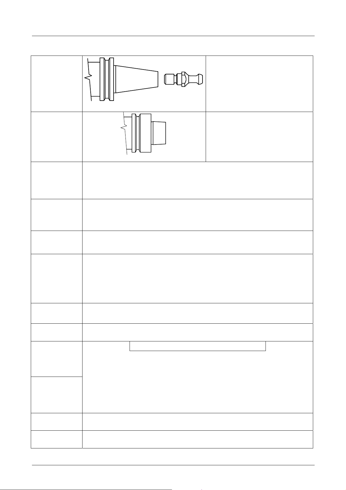
1.11 GLOSSARY
ISO
HSK
Value of the balancing of a rotating object according to the standard ISO 1940/1,
Degree or type
of dynamic
balancing
indicated by the letter G.
Low G values correspond to higher balancings; the maximum balancing precision is
G=0.4.
G takes on discrete values in relation to multiples of 2.5 (G=0.4 G=1 G=2.5 …).
ISO DIN69871 CONE HSD TIE-ROD
HSK DIN69893 CONE
Tool-holder cone hooking system,
described by the standard DIN 69871.
On the electrospindle there is a plate
similar to that alongside, indicating the
type of hook-up (ISO or HSK) and the
type of HSD tie-rod (see paragraph
6.6).
Tool-holder cone hooking system,
described by standard DIN 69893.
The electrospindle has a plate similar to
that alongside, indicating the type of
hook-up (ISO or HSK).
Routine
maintenance
Service S1
Service S6
Rated voltage
Rated
frequency
Torque
Power
All the activities intended to maintain the operating and functioning conditions of the
electrospindle as provided for by HSD S.p.A. at the moment of its launch on the market;
it is carried out through scheduled operations to adjust, repair and replace parts.
Function under constant load, of a duration sufficient to allow the electrospindle to attain
a thermal equilibrium.
The corresponding abbreviation is S1.
Sequence of identical operating cycles, each comprising a period of operation under
constant load and a period of operation without load while maintaining the rotational
speed; there is no rest period.
The corresponding abbreviation is S6, followed by the percentage ratio between the
period of operation under load and the length of the cycle.
Example: S6 40%.
40% period of operation under load, 60% period of operation in rotation without load).
(
Maximum power supply voltage of the electrospindle.
Minimum frequency at which rated voltage is supplied.
..Torque (Nm) = [ 60 · power (W) ] : [ 2 · Π · rpm ]..
Providing a precise physical definition of torque and power would be going beyond the
scope and possibility of this manual. Nevertheless the torque can be roughly
correlated to the force with which the tool contacts the piece being machined (and for
the same torque value, the force increases as the diameter of the tool decreases). The
power, on the other hand, is proportional to the torque and the rotational speed and
determines the maximum machining speed (taking into consideration the performance
of the tool, the characteristics of the material being machined and the type of
machining).
Nominal
characteristics
Coolant
All the various rated values reached in relation to the rated frequency.
Fluid, liquid or gas (including air) by means of which the heat is transferred from the
spindle to the atmosphere.
5801H0056 ________________________________________________________________ 9/181
Page 10

HSD
1.12 GUARANTEE CONDITIONS
HSD S.p.A. guarantees that the electrospindle has been inspected at its plant with a positive result.
Works under warranty shall be performed free at the HSD S.p.A. facilities, transport at the
customer's expense; HSD S.p.A. shall not be liable for termination of production during the
warranty period.
The warranty does not cover faults due to normal wear of those parts which, by their nature, are
subject to rapid and continuous wear (e.g. gaskets, belts, bearings, etc.). In particular, HSD S.p.A.
gives no guarantee as to the working life of the bearings, as this depends on various factors
including: the degree of balancing of the tools, the types of machining operation, collisions and/or
mechanical stresses beyond the values indicated by the manufacturer.
HSD S.p.A. accepts no liability for faults in the conformity of the electrospindle caused by a failure
to observe the standards of the instruction manual or the incorrect operation or handling of the
electrospindle.
only if the faults have not been caused by tampering
parts and/or replacing components not provided for and not authorised in this manual and, in any
case, without the prior written approval of HSD S.p.A.
On no account shall HSD S.p.A. or its suppliers be responsible for damage (including but not limited
to damage to the physical integrity of the product or damages due to loss or reduced earnings,
stoppages in production, loss of information or other economic losses) resulting from the use of
HSD products, even in cases where HSD S.p.A. has been warned of the possibility of such damage.
The buyer shall therefore have a right to replacement of parts found to be defective
, namely by installing non-original HSD spare
The buyer's warranty shall be voided if HSD S.p.A. is not notified in detail, in writing, of the nature
of any faults discovered in the electrospindle within 15 days of the fault being discovered. The
buyer's warranty shall also be voided in the event that he does not allow the seller to carry out any
requested inspections, or if the seller requests the return of the defective parts and the buyer fails
to return them within two weeks of the request.
Measured drawings and photographs are provided purely as reference examples for a simpler
understanding of the text.
In line with its policy of continuous development and advancement of the product, the company
reserves the right to modify both its functional and aesthetic characteristics, to vary the design of
any functional element or accessory, or to suspend production and delivery; this without
undertaking to give notice to anyone and without incurring any other obligation. Furthermore, HSD
S.p.A. reserves the right to make any structural or functional modifications, as well as the
modification of the supplied spare parts and accessories, without the obligation of communicating
these changes to anyone or assuming any other obligation.
5801H0056 _______________________________________________________________ 10/181
Page 11
HSD
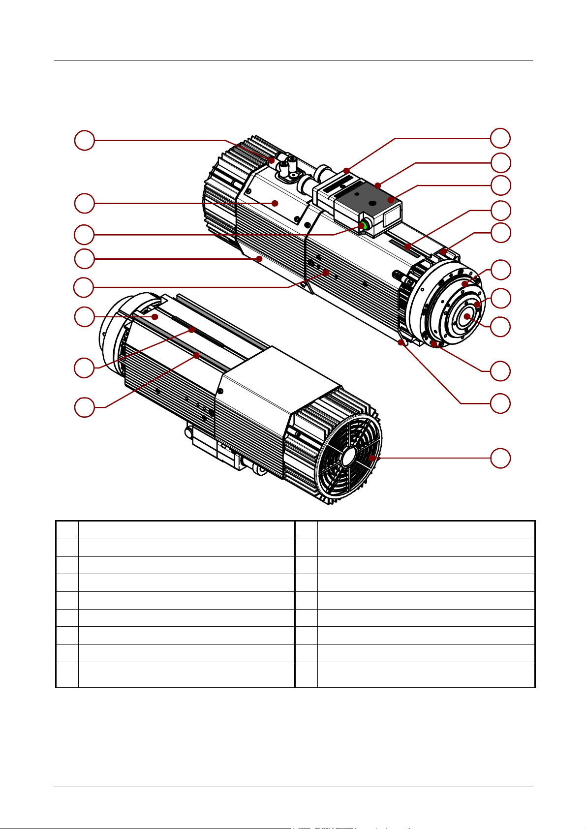
2 TECHNICAL SPECIFICATIONS
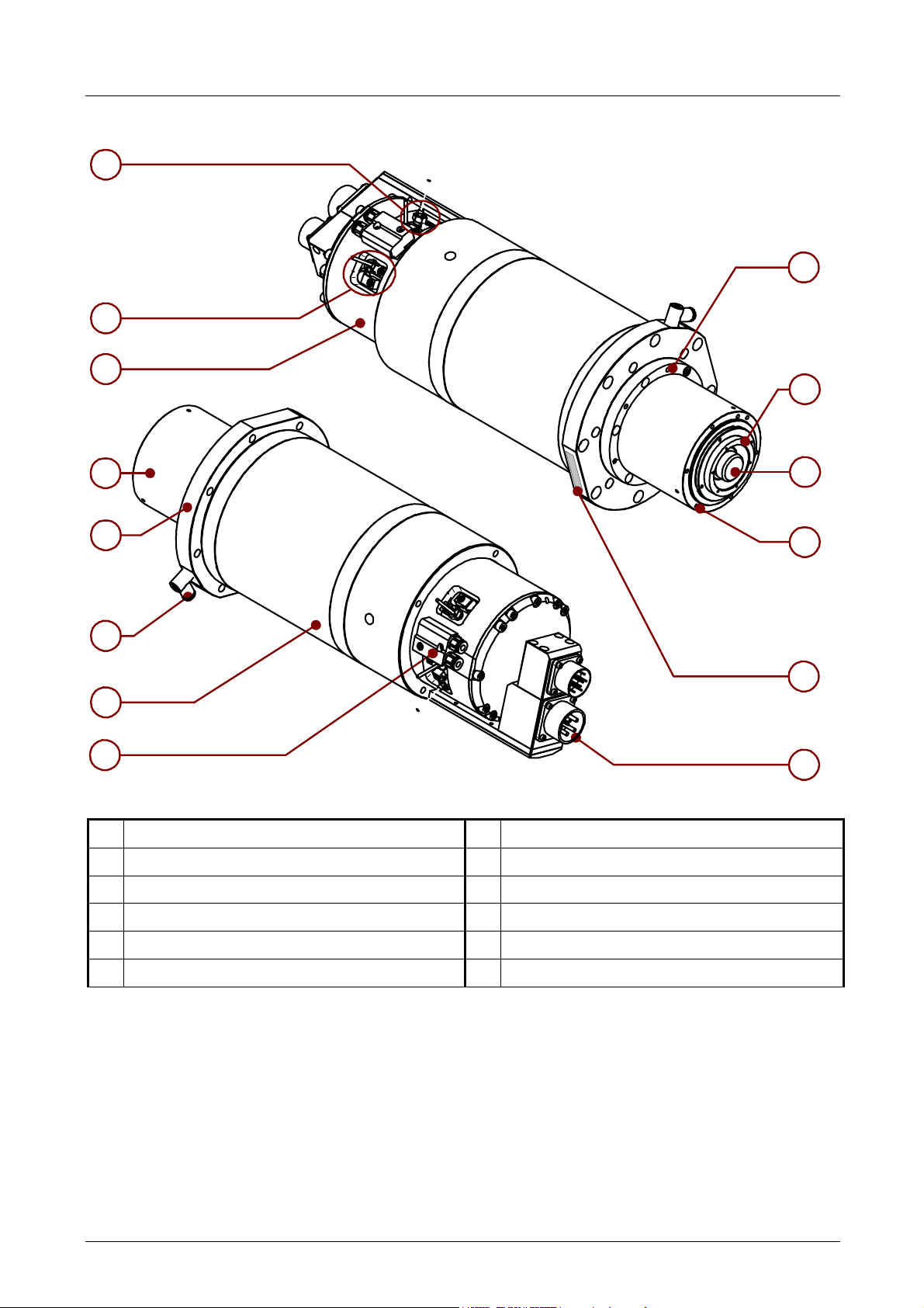
2.1 MAIN PARTS OF ES915/ES919/ES929/ES988
12
13
14
15
9
16
17
18
1
2
3
4
5
6
7
8
9
10
11
1 Movable electrical connectors 10 Framework
2 Fixed electrical connectors 11 Electric fan (air-cooled versions only)
3 EC marking plate 12 Pneumatic connectors
4 Serial number 13 Cover of the sensor area
5 Connector for sensor on accessories (e.g. C-axis) 14 Button for the manual release of the tool-holder
6 “Nose” 15 Pneumatic cylinder
7 Shaft 16 Resting surface
8 Tool hooking system 17 Seat for centring tang
Threaded bores for accessories
9
(on the sides and the front flange)
18 “T” slot for fixing
5801H0056 _______________________________________________________________ 11/181
Page 12
HSD
2.2 MAIN PARTS OF MODELS ES884 - ES888
1
1
2
8
9
3
4
5
6
7
1 Sensor area 7 Pneumatic connections
2 Pneumatic cylinder 8 M6 threaded bores for accessories
3 “Nose” 9 Shaft
4 Fixing surface 10 Tool hooking system
10
8
11
12
5 Pressurisation connector 11 Serial number
6 Framework 12 Electrical connectors
5801H0056 _______________________________________________________________ 12/181
Page 13
HSD
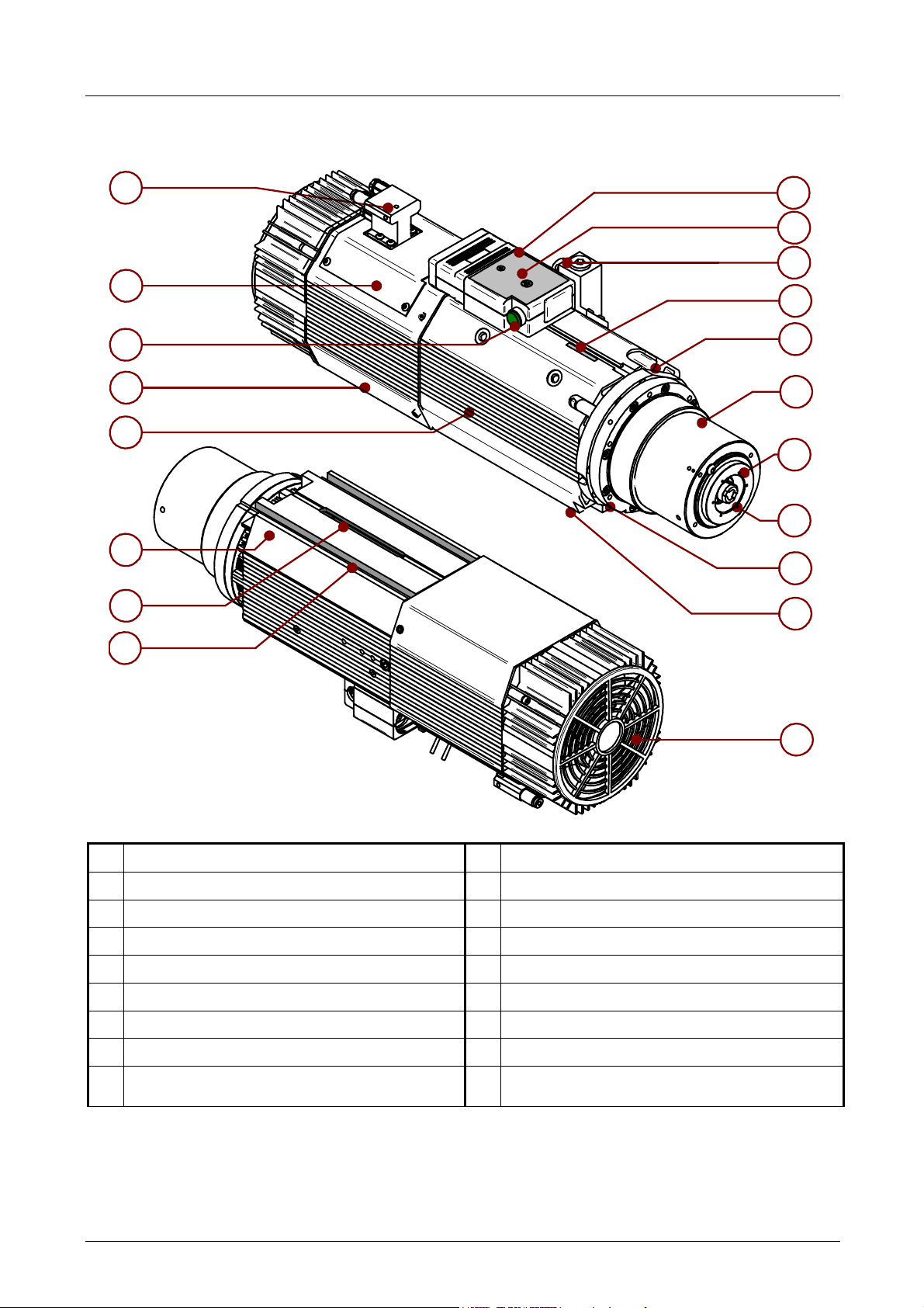
2.3 MAIN PARTS OF MODEL ES939
12
13
14
15
9
16
17
1
2
3
4
5
6
7
8
9
10
18
1 Fixed electrical connectors 10 Framework
2 EC marking plate 11 Electric fan (air-cooled versions only)
3 Encoder connector 12 Pneumatic connectors
4 Serial number 13 Cover of the sensor area
5 Connector for sensor on accessories (e.g. C-axis) 14 Button for the manual release of the tool holder
6 “Nose” 15 Pneumatic cylinder
7 Shaft 16 Resting surface
8 Tool hooking system 17 Seat for centring tang
Threaded bores for accessories
9
(on the sides and the front flange)
18 “T” slot for fixing
11
5801H0056 _______________________________________________________________ 13/181
Page 14
HSD
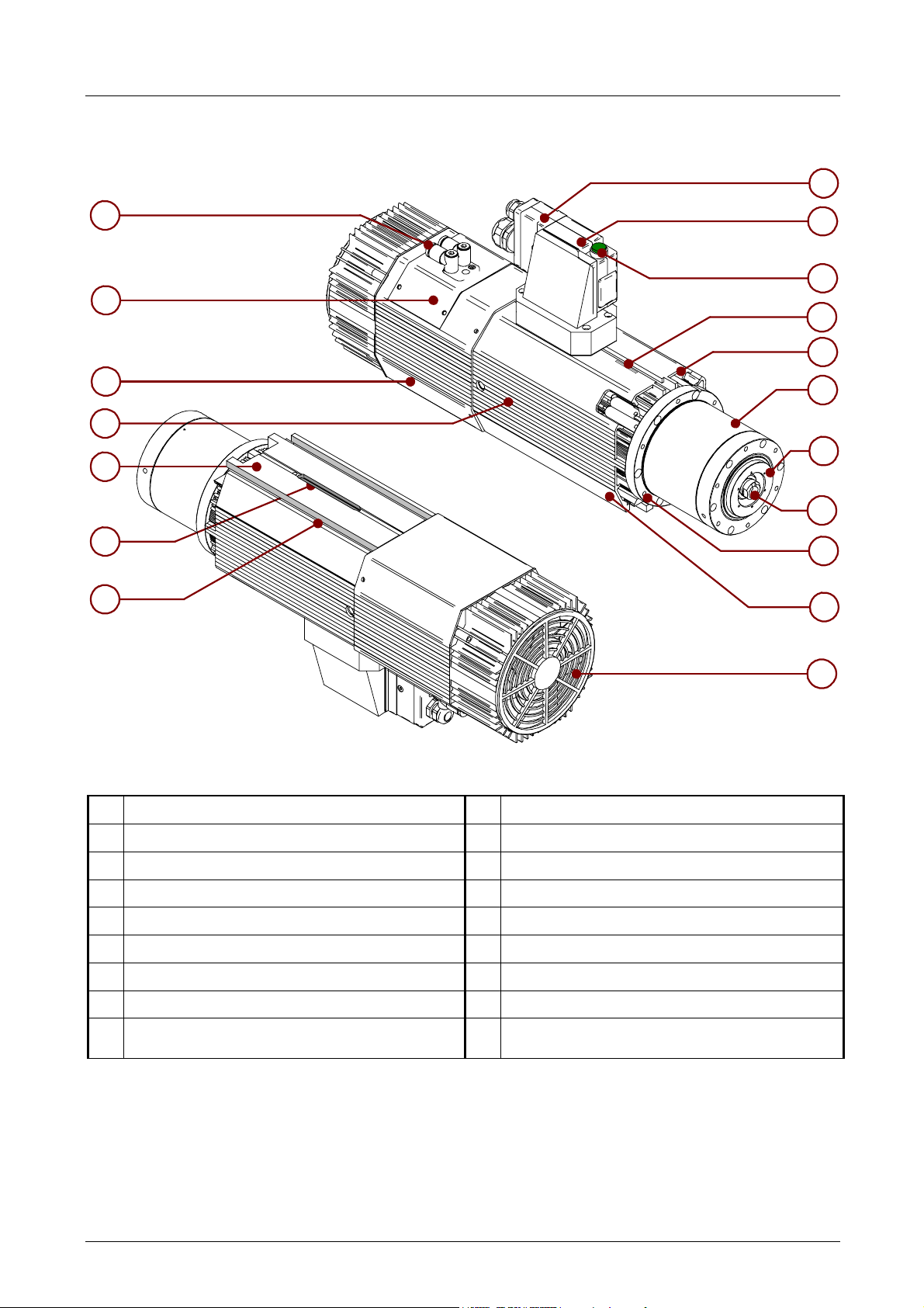
2.4 VARIATIONS WITH VERTICAL MOUNTING PLATE
1
12
13
14
9
15
16
17
2
3
4
5
6
7
8
9
10
1 Movable electrical connectors 10 Framework
2 Fixed electrical connectors 11 Electric fan (air-cooled versions only)
3 Button for the manual release of the tool-holder 12 Pneumatic connectors
4 Serial number 13 Cover of the sensor area
5 Connector for sensor on accessories (e.g. C-axis) 14 Pneumatic cylinder
6 “Nose” 15 Resting surface
7 Shaft 16 Seat for centring tang
8 Tool hooking system 17 “T” slot for fixing
Threaded bores for accessories
9
(on the sides and the front flange)
11
5801H0056 _______________________________________________________________ 14/181
Page 15
HSD
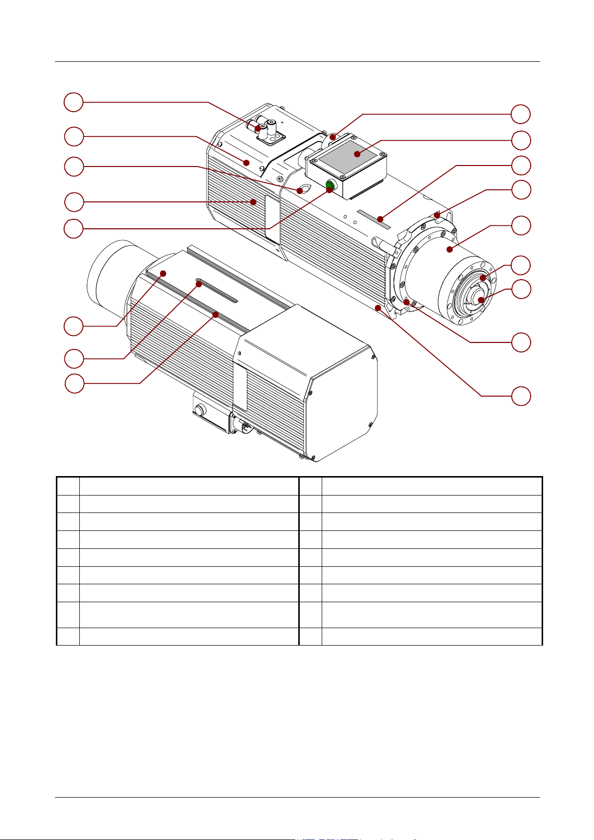
2.5 VARIATIONS WITH MILITARY CONNECTORS
10
1
11
12
13
14
15
16
17
2
3
4
5
6
7
8
9
1 Fixed electrical connectors 10 Pneumatic connectors
2 EC marking plate 11 Cover of the sensor area
3 Serial number 12 Motor cooling liquid inlet / outlet
4 Connector for sensor on accessories (e.g. C-axis) 13 Pneumatic cylinder
5 “Nose” 14 Button for the manual release of the tool-holder
6 Shaft 15 Resting surface
7 Tool hooking system 16 Seat for centring tang
Threaded bores for accessories
8
(on the sides and the front flange)
9 Framework
17 “T” slot for fixing
5801H0056 _______________________________________________________________ 15/181
Page 16

HSD
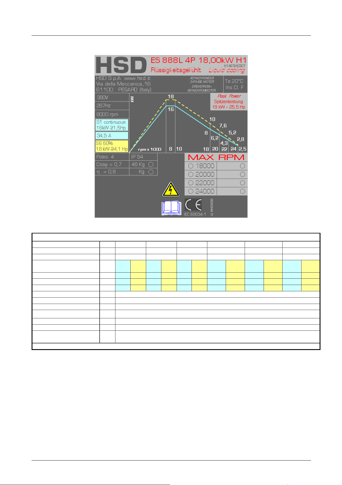
2.6 TECHNICAL CARDS ES884
H1423H0292 Rev.02 (120.150.4A )
Rated voltage (*)
Rated frequency Hz 267 333 500 600
Rated speed rpm 8,000 10000 15,000 18,000
Duty type
Rated power kW 16.0
Rated torque Nm 19
Rated current A 34.5
Rated output η 0.8
Power factor cos φ 0.7
Number of poles 4
Type of insulation F
IP rating 54
Type of cooling Raffreddamento a liquido / Flüssigkeit / Liquid cooling
Weight of
LONG NOSE version
[(*) supplied by inverter]
V 380 380 380 380
S1
cont
kg ~ 57
S6
60%
18.0
21.5
45
S1
cont
16.0
15.3
34.5
S6
60%
18.0
17.2
45
S1
cont
11.0
7.0
23.7
S6
60%
13.0
8.3
32.6
S1
cont
8.0
4.2
18.0
S6
60%
10.0
5.3
26.0
5801H0056 _______________________________________________________________ 16/181
Page 17

HSD
SP120.150.4A
Description
Potenza nominale / rated power / nennleistung (S1)
Corrente nominale / rated current / nennstrom (S1)
Tensione nominale concatenata / line rated voltage / nennspannung
Velocità nominale al carico nominale/ rated speed at rated load /
nenndrehzahl bei nennlast
Frequenza nominale / rated frequency / nennfrequenz
Tensione a vuoto concatenata / no-load line voltage / leerlaufspannung
bei nennflussu
Corrente a vuoto / no-load current / leerlaufstrom
Resistenza dello statore / stator resistance / standerwiderstand kalt
(20°C)
Resistenza del rotore /rotor resistance / lauferwiderstand kalt (20°C)
Reattanza di dispersione dello statore / stator leakage reactance /
standerstreureaktanz
Reattanza di dispersione del rotore /rotor leakage reactance /
lauferstreureaktanz
Reattanza del campo principale / main field reactance /
hauptfeldreaktanz
Velocità di inizio indebolimento del campo / field weakening initial speed
speed / Einsatzdrehzahl feldschwachung
Velocità massima del motore / motor maximum speed /
Maximaldrehzahl
Fattore di potenza / power factor / nennleistungsfactor
Momento di inerzia del rotore / moment of inertia
Collegamento / circuit connection / schaltungsart
Unit of
measur
ement
kW
A
V
Rpm
Hz
V
A
Ω
Ω
Ω
Ω
Ω
Rpm
Rpm
Kg m2
Y or D
Value
16
34.5
380
7810
267
370
11
0.12
0.2
1
1.7
19
8000
18000
0.8
0,0025
Y
5801H0056 _______________________________________________________________ 17/181
Page 18
HSD
2.7 TECHNICAL CARDS ES888
H1423H0307 Rev.00 ( Ref.: H2120H0120 / SP.120.150.4A )
Rated voltage (*) V
Rated frequency Hz
Rated speed rpm
Duty type
Rated power kW
Rated torque Nm
Rated current A
Rated output η
Power factor cos φ
Number of poles
Type of insulation
IP rating
Type of cooling
Weight of
LONG NOSE version
[(*) supplied by inverter]
kg
380 380 380 380 380 380
267 333 600 667 733 800
8,000 10000 18,000 20,000 22000 24,000
S1
cont
16
19
34.5
4
S6
60%
18
21.5
45
S6
S1
60%
cont
18
16
17.2
15.3
45
34.5
Raffreddamento a liquido / Flüssigkeit / Liquid cooling
S1
cont
8
4.2
18
S6
60%
10
5.3
26
S1
cont
6.2
3
14.3
0.8
0.7
F
54
~ 46
S6
60%
7.6
3.6
17.2
S1
cont
4.3
1.9
8
60%
S6
5.2
2.3
11
S1
cont
2.5
1.0
4.6
S6
60%
2.8
1.1
5
5801H0056 _______________________________________________________________ 18/181
Page 19

HSD
SP120.150.4A
Description
Potenza nominale / rated power / nennleistung (S1)
Corrente nominale / rated current / nennstrom (S1)
Tensione nominale concatenata / line rated voltage / nennspannung
Velocità nominale al carico nominale/ rated speed at rated load /
nenndrehzahl bei nennlast
Frequenza nominale / rated frequency / nennfrequenz
Tensione a vuoto concatenata / no-load line voltage /
leerlaufspannung
bei nennflussu
Corrente a vuoto / no-load current / leerlaufstrom
Resistenza dello statore / stator resistance / standerwiderstand kalt
(20°C)
Resistenza del rotore /rotor resistance / lauferwiderstand kalt (20°C)
Reattanza di dispersione dello statore / stator leakage reactance /
standerstreureaktanz
Reattanza di dispersione del rotore /rotor leakage reactance /
lauferstreureaktanz
Reattanza del campo principale / main field reactance /
hauptfeldreaktanz
Velocità di inizio indebolimento del campo / field weakening initial
speed
speed / Einsatzdrehzahl feldschwachung
Velocità massima del motore / motor maximum speed /
Maximaldrehzahl
Fattore di potenza / power factor / nennleistungsfactor
Momento di inerzia del rotore / moment of inertia
Collegamento / circuit connection / schaltungsart
Unit of
measur
ement
kW
A
V
Rpm
Hz
V
A
Ω
Ω
Ω
Ω
Ω
Rpm
Rpm
Kg m2
Y or D
Value
16
34.5
380
7810
267
370
11
0.12
0.2
1
1.7
19
8000
18000
0.8
0.0025
Y
5801H0056 _______________________________________________________________ 19/181
Page 20
HSD
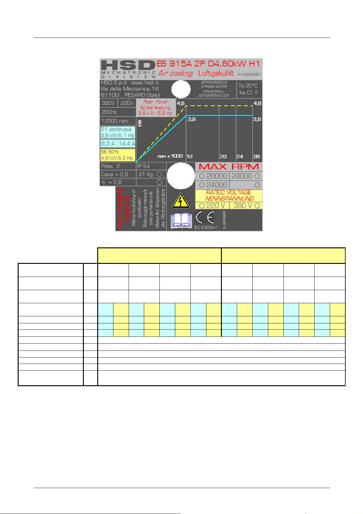
2.8 TECHNICAL CARDS ES915
H1423H0221 Rev.04
(SP.110.70.24)
Rated voltage (*) V 380 380 380 380 220 220 220 220
Rated frequency Hz 200 333 400 466 200 333 400 466
Rated speed rpm 12000 20000 24000 28000 12000 20000 24000 28000
Duty type
Rated power kW 3.8 4.6 3.8 4.6 3.8 4.6 3.8 4.6 3.8 4.6 3.8 4.6 3.8 4.6 3.8 4.6
Rated torque Nm 3 3.7 1.8 2.2 1.5 1.8 1.3 1.6 3 3.7 1.8 2.2 1.5 1.8 1.3 1.6
Rated current A 8.3 10 8.3 10 8.3 10 8.3 10 14.4 17.3 14.4 17.3 14.4 17.3 14.4 17.3
Rated output η
Power factor cosϕ
Number of poles 2
Type of insulation F
Type of cooling Elettroventola / Elektrolüfter / Cooling fan
Weight of
SHORT NOSE version
[(*) supplied by inverter]
STAR CONNECTION DELTA CONNECTION
S1
S6
S1
S6
S1
S6
S1
S6
S1
S6
S1
S6
S1
S6
S1
S6
cont
60%
cont
60%
cont
60%
cont
60%
cont
60%
cont
60%
cont
60%
cont
60%
0.8
0.8
kg ~ 21
5801H0056 _______________________________________________________________ 20/181
Page 21

HSD
SP 110.70.24
Description
Potenza nominale / rated power / nennleistung (S1)
Corrente nominale / rated current / nennstrom (S1)
Tensione nominale concatenata / line rated voltage / nennspannung
Velocità nominale al carico nominale/ rated speed at rated load /
nenndrehzahl bei nennlast
Frequenza nominale / rated frequency / nennfrequenz
Tensione a vuoto concatenata / no-load line voltage / leerlaufspannung
bei nennflussu
Corrente a vuoto / no-load current / leerlaufstrom
Resistenza dello statore / stator resistance / standerwiderstand kalt
(20°C)
Resistenza del rotore /rotor resistance / lauferwiderstand kalt (20°C)
Reattanza di dispersione dello statore / stator leakage reactance /
standerstreureaktanz
Reattanza di dispersione del rotore /rotor leakage reactance /
lauferstreureaktanz
Reattanza del campo principale / main field reactance /
hauptfeldreaktanz
Velocità di inizio indebolimento del campo / field weakening initial speed
speed / Einsatzdrehzahl feldschwachung
Velocità massima del motore / motor maximum speed /
Maximaldrehzahl
Fattore di potenza / power factor / nennleistungsfactor
Collegamento / circuit connection / schaltungsart
Unit of
measur
ement
kW
A
V
Rpm
Hz
V
A
Ω
Ω
Ω
Ω
Ω
Rpm
Rpm
Y or D
Value
3.7
8.3
380
11800
200
370
2.6
0.67
0.65
2.1
3.8
82
12000
12000
0.8
Y
5801H0056 _______________________________________________________________ 21/181
Page 22
HSD
H1423H0206_Rev02 SP.110.070.42
Rated voltage (*)
Rated frequency
Rated speed
Duty type
Rated power
Rated torque
Rated current
Rated output η
Power factor cosϕ
Number of poles
Type of insulation
Type of cooling
Weight of
SHORT NOSE version
Weight of
LONG NOSE version
[(*) supplied by inverter]
V 380 380 380 380 380
Hz 400 500 667 800 933
rpm 12,000 15,000 20,000 24,000 28,000
kW
Nm
A
0.86
0.82
4
F
kg ~ 21
kg ~ 26
S1
cont
5
4
12
S6
60%
6
4.8
14
S1
cont
3.2
10.5
Elettroventola / Elektrolüfter / Cooling fan
S6
60%
5
3.8
14
S1
cont
6
3.9
1.7
9.2
S6
60%
4.6
2.2
10.5
S1
cont
3
1.2
7
60%
3.5
1.4
S6
8
S1
cont
2.1
0.7
4
S6
60%
2.4
0.8
4.5
5801H0056 _______________________________________________________________ 22/181
Page 23

HSD
SP110.70.42_Air
Description
Potenza nominale / rated power / nennleistung (S1)
Corrente nominale / rated current / nennstrom (S1)
Tensione nominale concatenata / line rated voltage / nennspannung
Velocità nominale al carico nominale/ rated speed at rated load /
nenndrehzahl bei nennlast
Frequenza nominale / rated frequency / nennfrequenz
Tensione a vuoto concatenata / no-load line voltage /
leerlaufspannung
bei nennflussu
Corrente a vuoto / no-load current / leerlaufstrom
Resistenza dello statore / stator resistance / standerwiderstand kalt
(20°C)
Resistenza del rotore /rotor resistance / lauferwiderstand kalt (20°C)
Reattanza di dispersione dello statore / stator leakage reactance /
standerstreureaktanz
Reattanza di dispersione del rotore /rotor leakage reactance /
lauferstreureaktanz
Reattanza del campo principale / main field reactance /
hauptfeldreaktanz
Velocità di inizio indebolimento del campo / field weakening initial
speed
speed / Einsatzdrehzahl feldschwachung
Velocità massima del motore / motor maximum speed /
Maximaldrehzahl
Fattore di potenza / power factor / nennleistungsfactor
Momento di inerzia del rotore / moment of inertia
Collegamento / circuit connection / schaltungsart
Unit of
measur
ement
kW
A
V
Rpm
Hz
V
A
Ω
Ω
Ω
Ω
Ω
Rpm
Rpm
Kg m2
Y or D
Value
5
10.5
380
11850
400
370
4.3
0.27
0.24
1.6
3.2
50
12000
24000
0.85
1.1E-03
Y
5801H0056 _______________________________________________________________ 23/181
Page 24

HSD
H1423H0207 Rev.02 (ST 110.070.42)
Rated voltage (*) V 380 380 380 380 380 380
Rated frequency Hz 400 500 600 667 733 933
Rated speed rpm 12,000 15,000 18,000 20,000 22000 28,000
S1
S6
S1
S6
S1
S6
S1
S6
S1
S6
S1
Duty type
Rated power kW 6.5
Rated torque Nm 5.2
Rated current A 15
Rated output η
Power factor cosϕ
Number of poles 4
Type of insulation F
Type of cooling
Weight of
LONG NOSE version
[(*) supplied by inverter]
cont
50%
cont
50%
cont
50%
7.5
6
18
0.82
0.74
kg ~ 29
7.5
6.5
4.8
4.1
18
15
Raffreddamento a liquido / Flüssigkeit / Liquid cooling
6.1
3.2
14
6.7
3.6
15.7
cont
5.8
2.8
13
50%
6.4
3.1
16
cont
5.5
2.4
13.1
50%
6
2.6
14.1
cont
7.5
S6
50%
3
3
1
1
7.5
5801H0056 _______________________________________________________________ 24/181
Page 25

HSD
SP110.70.42_Liquid
Description
Potenza nominale / rated power / nennleistung (S1)
Corrente nominale / rated current / nennstrom (S1)
Tensione nominale concatenata / line rated voltage / nennspannung
Velocità nominale al carico nominale/ rated speed at rated load /
nenndrehzahl bei nennlast
Frequenza nominale / rated frequency / nennfrequenz
Tensione a vuoto concatenata / no-load line voltage /
leerlaufspannung
bei nennflussu
Corrente a vuoto / no-load current / leerlaufstrom
Resistenza dello statore / stator resistance / standerwiderstand kalt
(20°C)
Resistenza del rotore /rotor resistance / lauferwiderstand kalt (20°C)
Reattanza di dispersione dello statore / stator leakage reactance /
standerstreureaktanz
Reattanza di dispersione del rotore /rotor leakage reactance /
lauferstreureaktanz
Reattanza del campo principale / main field reactance /
hauptfeldreaktanz
Velocità di inizio indebolimento del campo / field weakening initial
speed
speed / Einsatzdrehzahl feldschwachung
Velocità massima del motore / motor maximum speed /
Maximaldrehzahl
Fattore di potenza / power factor / nennleistungsfactor
Momento di inerzia del rotore / moment of inertia
Collegamento / circuit connection / schaltungsart
Unit of
measur
ement
kW
A
V
Rpm
Hz
V
A
Ω
Ω
Ω
Ω
Ω
Rpm
Rpm
Kg m2
Y or D
Value
6.5
13.2
380
11850
400
370
4.3
0.27
0.24
1.6
3.2
50
12000
24000
0.85
1.1E-03
Y
5801H0056 _______________________________________________________________ 25/181
Page 26
HSD
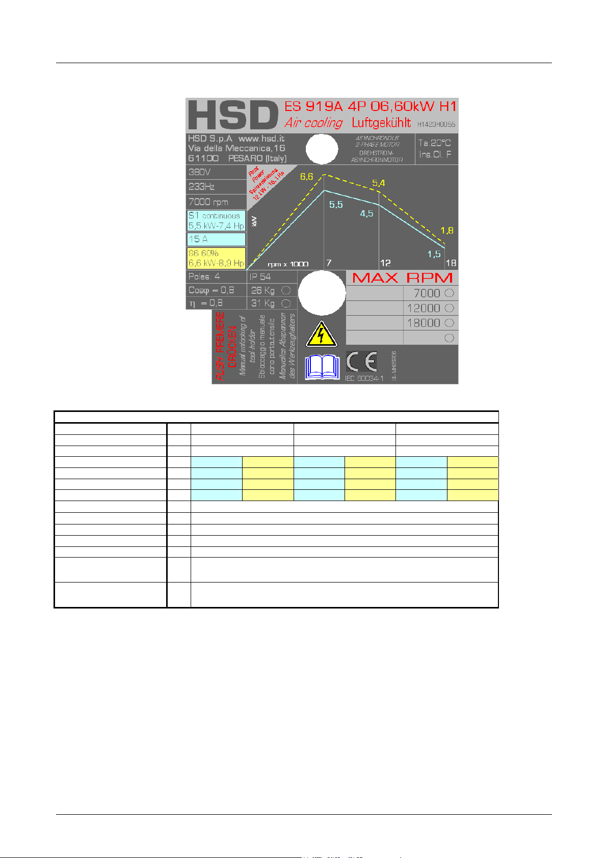
2.9 TECHNICAL CARDS ES919
H1423H0055 Rev.03 (SP.110.130.45)
Rated voltage (*) V 380 380 380
Rated frequency Hz 233 400 600
Rated speed rpm 7000 12,000 18,000
Duty type S1 cont S6 60% S1 cont S6 60% S1 cont S6 60%
Rated power kW 5.5
Nm 7.5
Rated current A 15
Rated output η
Power factor cosϕ
Number of poles 4
Type of insulation F
Type of cooling
Weight of
SHORT NOSE version
Weight of
LONG NOSE version
[(*) supplied by inverter]
0.8
0.8
kg ~ 26
kg ~ 31
6.6
9
18
Elettroventola / Elektrolüfter / Cooling fan
4.5
3.6
14
5.4
4.3
17
1.5
0.8
6.5
1.8
1
8
5801H0056 _______________________________________________________________ 26/181
Page 27

HSD
SP110.130.45
Description
Potenza nominale / rated power / nennleistung (S1)
Corrente nominale / rated current / nennstrom (S1)
Tensione nominale concatenata / line rated voltage / nennspannung
Velocità nominale al carico nominale/ rated speed at rated load /
nenndrehzahl bei nennlast
Frequenza nominale / rated frequency / nennfrequenz
Tensione a vuoto concatenata / no-load line voltage /
leerlaufspannung
bei nennflussu
Corrente a vuoto / no-load current / leerlaufstrom
Resistenza dello statore / stator resistance / standerwiderstand kalt
(20°C)
Resistenza del rotore /rotor resistance / lauferwiderstand kalt (20°C)
Reattanza di dispersione dello statore / stator leakage reactance /
standerstreureaktanz
Reattanza di dispersione del rotore /rotor leakage reactance /
lauferstreureaktanz
Reattanza del campo principale / main field reactance /
hauptfeldreaktanz
Velocità di inizio indebolimento del campo / field weakening initial
speed
speed / Einsatzdrehzahl feldschwachung
Velocità massima del motore / motor maximum speed /
Maximaldrehzahl
Fattore di potenza / power factor / nennleistungsfactor
Momento di inerzia del rotore / moment of inertia
Collegamento / circuit connection / schaltungsart
Unit of
measur
ement
kW
A
V
Rpm
Hz
V
A
Ω
Ω
Ω
Ω
Ω
Rpm
Rpm
Kg m2
Y or D
Value
5.5
15
380
6870
233
355
4.2
0.38
0.4
3.4
2.6
49
7000
18000
0.85
1.8E-03
D
5801H0056 _______________________________________________________________ 27/181
Page 28
HSD
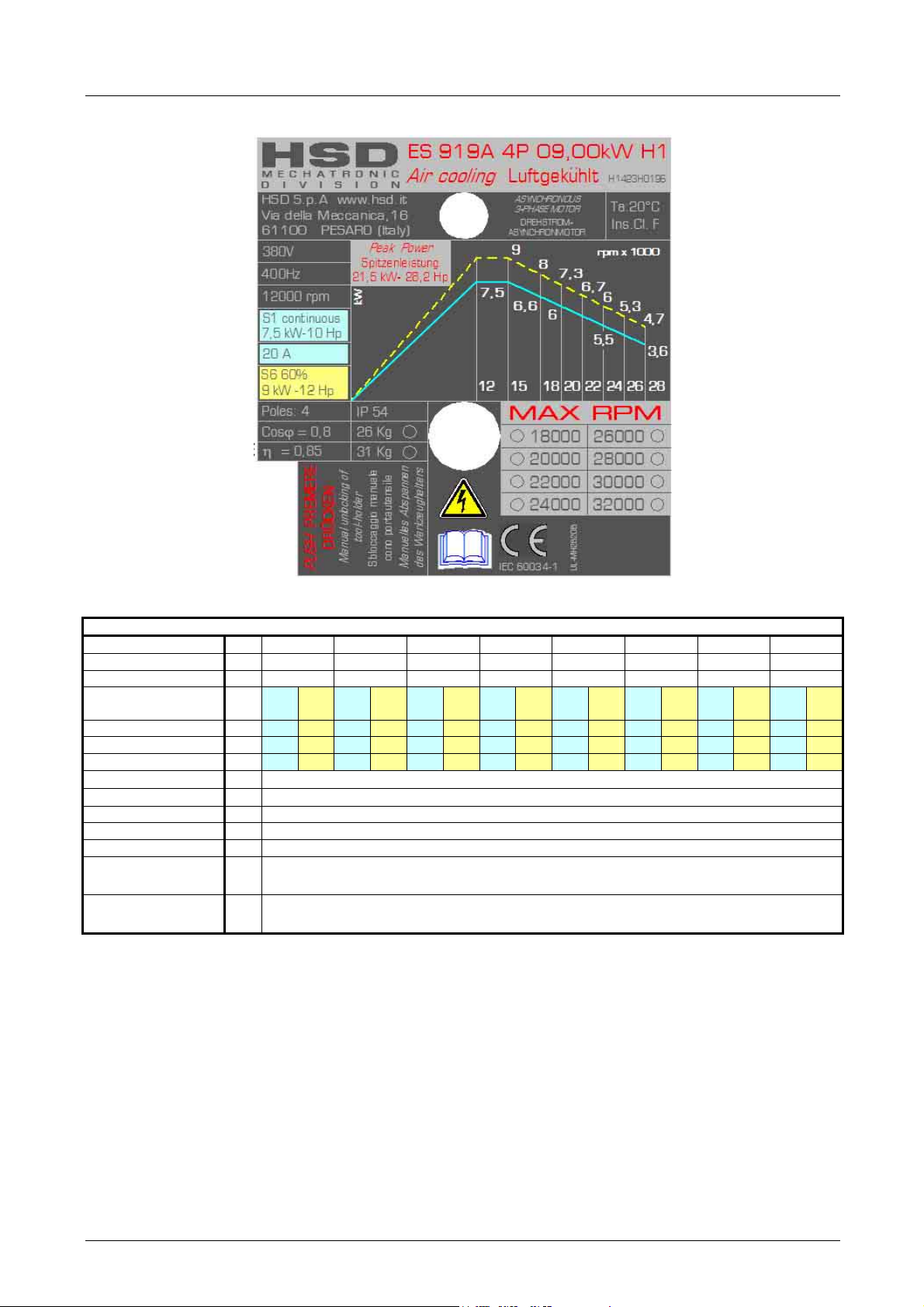
H1423H0196 Rev.01 (SP.110.130.48)
Rated voltage (*) V 380 380 380 380 380 380 380 380
Rated frequency Hz 400 500 600 667 733 800 867 933
Rated speed rpm 12,000 15,000 18,000 20,000 22000 24,000 26000 28,000
S1
S6
S1
S6
S1
S6
S1
S6
S1
S6
S1
S6
S1
S6
S1
Duty type
Rated power kW 7.5 9 7.5 9 6.6 8 6 7.3 5.8 6.7 5.5 6 4.2 5.3 3.6 4.7
Rated torque Nm 6 7.2 4.8 5.7 3.5 4.2 2.9 3.5 2.5 2.9 2.2 2.4 1.5 2 1.2 1.6
Rated current A 20 22.5 17 20.5 16 18.5 15 17.5 13 15 13 14 10 12.6 11.5 15
Rated output η
Power factor cosϕ
Number of poles 4
Type of insulation F
Type of cooling Elettroventola / Elektrolüfter / Cooling fan
Weight of
SHORT NOSE version
Weight of
LONG NOSE version
[(*) supplied by inverter]
cont
60%
cont
60%
cont
60%
cont
60%
cont
60%
cont
60%
cont
60%
0.85
0.8
kg ~ 26
kg ~ 31
cont
S6
60%
5801H0056 _______________________________________________________________ 28/181
Page 29

HSD
SP110.130.48 (air-cooled)
Description
Potenza nominale / rated power / nennleistung (S1)
Corrente nominale / rated current / nennstrom (S1)
Tensione nominale concatenata / line rated voltage / nennspannung
Velocità nominale al carico nominale/ rated speed at rated load /
nenndrehzahl bei nennlast
Frequenza nominale / rated frequency / nennfrequenz
Tensione a vuoto concatenata / no-load line voltage /
leerlaufspannung
bei nennflussu
Corrente a vuoto / no-load current / leerlaufstrom
Resistenza dello statore / stator resistance / standerwiderstand kalt
(20°C)
Resistenza del rotore /rotor resistance / lauferwiderstand kalt (20°C)
Reattanza di dispersione dello statore / stator leakage reactance /
standerstreureaktanz
Reattanza di dispersione del rotore /rotor leakage reactance /
lauferstreureaktanz
Reattanza del campo principale / main field reactance /
hauptfeldreaktanz
Velocità di inizio indebolimento del campo / field weakening initial
speed
speed / Einsatzdrehzahl feldschwachung
Fattore di potenza / power factor / nennleistungsfactor
Momento di inerzia del rotore / moment of inertia
Collegamento / circuit connection / schaltungsart
Unit of
measur
ement
kW
A
V
Rpm
Hz
V
A
Ω
Ω
Ω
Ω
Ω
Rpm
Kg m2
Y or D
Value
7.5
20
380
11910
400
360
12
0.12
0.14
1.2
1.9
25
12000
0.85
1.8E-03
Y
5801H0056 _______________________________________________________________ 29/181
Page 30
HSD
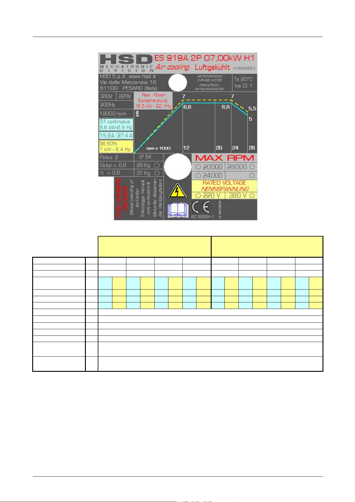
H1423H0223 Rev.01
(SP.110.130.29)
Rated voltage (*) V 380 380 380 380 220 220 220 220
Rated frequency Hz 200 333 400 466 200 333 400 466
Rated speed rpm 12,000 20,000 24,000 28,000 12,000 20,000 24,000 28,000
Duty type
Rated power kW 6.6 7 6.6 7 6.6 7 5 5.5 6.6 7 6.6 7 6.6 7 5 5.5
Rated torque Nm 5.3 5.6 3.2 3.3 2.6 2.8 1.7 1.9 5.3 5.6 3.2 3.3 2.6 2.8 1.7 1.9
Rated current A 15.8 18 15.8 18 15.8 18 15 17 27.4 31.2 27.4 31.2 27.4 31.2 26 29.4
Rated output η
Power factor cosϕ
Number of poles 2
Type of insulation F
Type of cooling Elettroventola / Elektrolüfter / Cooling fan
Weight of
SHORT NOSE version
Weight of
LONG NOSE version
[(*) supplied by inverter]
S1
cont
0.8
0.8
kg ~ 26
kg ~ 31
COLLEGAMENTO STELLA
STERNSCHALTUNG
STAR CONNECTION
S6
S1
S6
S1
60%
cont
60%
cont
60%
S6
S1
cont
S6
60%
COLLEGAMENTO TRIANGOLO
DREIECKSCHALTUNG
DELTA CONNECTION
S1
S6
S1
S6
S1
cont
60%
cont
60%
cont
S6
60%
S1
cont
S6
60%
5801H0056 _______________________________________________________________ 30/181
Page 31

HSD
SP110.130.29 (delta connection)
Description
Potenza nominale / rated power / nennleistung (S1)
Corrente nominale / rated current / nennstrom (S1)
Tensione nominale concatenata / line rated voltage /
nennspannung
Velocità nominale al carico nominale/ rated speed at rated load /
nenndrehzahl bei nennlast
Frequenza nominale / rated frequency / nennfrequenz
Tensione a vuoto concatenata / no-load line voltage /
leerlaufspannung
bei nennflussu
Corrente a vuoto / no-load current / leerlaufstrom
Resistenza dello statore / stator resistance / standerwiderstand
kalt (20°C)
Resistenza del rotore /rotor resistance / lauferwiderstand kalt
(20°C)
Reattanza di dispersione dello statore / stator leakage reactance /
standerstreureaktanz
Reattanza di dispersione del rotore /rotor leakage reactance /
lauferstreureaktanz
Reattanza del campo principale / main field reactance /
hauptfeldreaktanz
Velocità di inizio indebolimento del campo / field weakening initial
speed
speed / Einsatzdrehzahl feldschwachung
Velocità massima del motore / motor maximum speed /
Maximaldrehzahl
Fattore di potenza / power factor / nennleistungsfactor
Momento di inerzia del rotore / moment of inertia
Collegamento / circuit connection / schaltungsart
Unit of
measur
ement
kW
A
V
Rpm
Hz
V
A
Ω
Ω
Ω
Ω
Ω
Rpm
Rpm
Kg m2
Y or D
Value
6.6
27.4
220
11840
200
211
17
0.07
0.09
0.29
0.6
7
12000
24000
0.65
1.6E-03
D
5801H0056 _______________________________________________________________ 31/181
Page 32

HSD
SP110.130.29 (star connection)
Description
Potenza nominale / rated power / nennleistung (S1)
Corrente nominale / rated current / nennstrom (S1)
Tensione nominale concatenata / line rated voltage / nennspannung
Velocità nominale al carico nominale/ rated speed at rated load /
nenndrehzahl bei nennlast
Frequenza nominale / rated frequency / nennfrequenz
Tensione a vuoto concatenata / no-load line voltage /
leerlaufspannung
bei nennflussu
Corrente a vuoto / no-load current / leerlaufstrom
Resistenza dello statore / stator resistance / standerwiderstand kalt
(20°C)
Resistenza del rotore /rotor resistance / lauferwiderstand kalt (20°C)
Reattanza di dispersione dello statore / stator leakage reactance /
standerstreureaktanz
Reattanza di dispersione del rotore /rotor leakage reactance /
lauferstreureaktanz
Reattanza del campo principale / main field reactance /
hauptfeldreaktanz
Velocità di inizio indebolimento del campo / field weakening initial
speed
speed / Einsatzdrehzahl feldschwachung
Velocità massima del motore / motor maximum speed /
Maximaldrehzahl
Fattore di potenza / power factor / nennleistungsfactor
Momento di inerzia del rotore / moment of inertia
Collegamento / circuit connection / schaltungsart
Unit of
measur
ement
kW
A
V
Rpm
Hz
V
A
Ω
Ω
Ω
Ω
Ω
Rpm
Rpm
Kg m2
Y or D
Value
6.6
15.8
380
11840
200
364
10
0.2
0.28
0.87
1.8
22
12000
24000
0.72
1.6E-03
Y
5801H0056 _______________________________________________________________ 32/181
Page 33

HSD
H1423H0224
Rev.02
(SP.110.130.29)
Rated voltage (*) V
Rated frequency Hz
Rated speed rpm
Duty type
Rated power kW
Rated torque Nm
Rated current A
Rated output η
Power factor
cos
ϕ
Number of poles
Type of insulation
Type of cooling
Weight of
SHORT NOSE
version
Weight of
LONG NOSE
version
[(*) supplied by
inverter]
kg
kg
COLLEGAMENTO STELLA
STERNSCHALTUNG
STAR CONNECTION
380 380 380 380 380 220 220 220 220 220
200 333 400 466 500 200 333 400 466 500
12,000 20,000 24,000 28,000 30000 12,000 20,000 24,000 28,000 30000
S1
S6
S1
S6
S1
S6
S1
S6
S1
cont
60%
cont
60%
cont
60%
cont
60%
6.6 8 6.6 8 6.6 8 5 5.5 4.2 4.3 6.6 8 6.6 8 6.6 8 5 5.5 4.2 4.3
5.3 6.4 3.2 3.8 2.6 3.2 1.7 1.9 1.3 1.4 5.3 6.4 3.2 3.8 2.6 3.2 1.7 1.9 1.3 1.4
15.8 18 15.8 18 15.8 18 15 17 12.3 13.4 27.4 31.2 27.4 31.2 27.4 31.2 26 29.4 23 23.3
cont
S6
60%
0.8
0.8
2
F
Elettroventola / Elektrolüfter / Cooling fan
~ 26
~ 31
COLLEGAMENTO TRIANGOLO
DREIECKSCHALTUNG
DELTA CONNECTION
S1
S6
S1
S6
S1
cont
60%
cont
60%
cont
S6
60%
S1
cont
S6
60%
S1
cont
S6
60%
5801H0056 _______________________________________________________________ 33/181
Page 34

HSD
SP110.130.29 (delta connection)
Description
Potenza nominale / rated power / nennleistung (S1)
Corrente nominale / rated current / nennstrom (S1)
Tensione nominale concatenata / line rated voltage / nennspannung
Velocità nominale al carico nominale/ rated speed at rated load /
nenndrehzahl bei nennlast
Frequenza nominale / rated frequency / nennfrequenz
Tensione a vuoto concatenata / no-load line voltage /
leerlaufspannung
bei nennflussu
Corrente a vuoto / no-load current / leerlaufstrom
Resistenza dello statore / stator resistance / standerwiderstand kalt
(20°C)
Resistenza del rotore /rotor resistance / lauferwiderstand kalt (20°C)
Reattanza di dispersione dello statore / stator leakage reactance /
standerstreureaktanz
Reattanza di dispersione del rotore /rotor leakage reactance /
lauferstreureaktanz
Reattanza del campo principale / main field reactance /
hauptfeldreaktanz
Velocità di inizio indebolimento del campo / field weakening initial
speed
speed / Einsatzdrehzahl feldschwachung
Velocità massima del motore / motor maximum speed /
Maximaldrehzahl
Fattore di potenza / power factor / nennleistungsfactor
Momento di inerzia del rotore / moment of inertia
Collegamento / circuit connection / schaltungsart
Unit of
measur
ement
kW
A
V
Rpm
Hz
V
A
Ω
Ω
Ω
Ω
Ω
Rpm
Rpm
Kg m2
Y or D
Value
6.6
27.4
220
11840
200
211
17
0.07
0.09
0.29
0.6
7
12000
24000
0.65
1.6E-03
D
5801H0056 _______________________________________________________________ 34/181
Page 35

HSD
SP110.130.29 (star connection)
Description
Potenza nominale / rated power / nennleistung (S1)
Corrente nominale / rated current / nennstrom (S1)
Tensione nominale concatenata / line rated voltage / nennspannung
Velocità nominale al carico nominale/ rated speed at rated load /
nenndrehzahl bei nennlast
Frequenza nominale / rated frequency / nennfrequenz
Tensione a vuoto concatenata / no-load line voltage /
leerlaufspannung
bei nennflussu
Corrente a vuoto / no-load current / leerlaufstrom
Resistenza dello statore / stator resistance / standerwiderstand kalt
(20°C)
Resistenza del rotore /rotor resistance / lauferwiderstand kalt (20°C)
Reattanza di dispersione dello statore / stator leakage reactance /
standerstreureaktanz
Reattanza di dispersione del rotore /rotor leakage reactance /
lauferstreureaktanz
Reattanza del campo principale / main field reactance /
hauptfeldreaktanz
Velocità di inizio indebolimento del campo / field weakening initial
speed
speed / Einsatzdrehzahl feldschwachung
Velocità massima del motore / motor maximum speed /
Maximaldrehzahl
Fattore di potenza / power factor / nennleistungsfactor
Momento di inerzia del rotore / moment of inertia
Collegamento / circuit connection / schaltungsart
Unit of
measur
ement
kW
A
V
Rpm
Hz
V
A
Ω
Ω
Ω
Ω
Ω
Rpm
Rpm
Kg m2
Y or D
Value
6.6
15.8
380
11840
200
364
10
0.2
0.28
0.87
1.8
22
12000
24000
0.72
1.6E-03
Y
5801H0056 _______________________________________________________________ 35/181
Page 36

HSD
H1423H0225 Rev.01 (SP.110.130.4H)
Rated voltage (*) V 380 380 380 380 380 380
Rated frequency Hz 400 500 600 667 733 800
Rated speed rpm 12,000 15,000 18,000 20,000 22000 24,000
Duty type
Rated power kW 9
Rated torque Nm 7.2
Rated current A 21
Rated output η
Power factor cosϕ
Number of poles 4
Type of insulation F
Type of cooling
Weight of
SHORT NOSE version
Weight of
LONG NOSE version
[(*) supplied by inverter]
S1
cont
0.85
0.85
kg ~ 26
kg ~ 31
S6
60%
10.5
8.7
25.3
S1
S6
S1
S6
S1
cont
60%
cont
60%
10.5
9
5.7
19.2
6.7
22.5
Elettroventola / Elektrolüfter / Cooling fan
8
4.2
17.5
9.4
5
20
cont
7.2
3.4
15.8
S6
60%
8.6
4.1
19
S1
cont
6.3
2.7
14
S6
60%
7.5
3.3
17
S1
cont
5.4
2.2
12.9
S6
60%
6.3
2.5
14.7
5801H0056 _______________________________________________________________ 36/181
Page 37

HSD
SP110.130.4H
Description
Potenza nominale / rated power / nennleistung (S1)
Corrente nominale / rated current / nennstrom (S1)
Tensione nominale concatenata / line rated voltage / nennspannung
Velocità nominale al carico nominale/ rated speed at rated load /
nenndrehzahl bei nennlast
Frequenza nominale / rated frequency / nennfrequenz
Tensione a vuoto concatenata / no-load line voltage /
leerlaufspannung
bei nennflussu
Corrente a vuoto / no-load current / leerlaufstrom
Resistenza dello statore / stator resistance / standerwiderstand kalt
(20°C)
Resistenza del rotore /rotor resistance / lauferwiderstand kalt (20°C)
Reattanza di dispersione dello statore / stator leakage reactance /
standerstreureaktanz
Reattanza di dispersione del rotore /rotor leakage reactance /
lauferstreureaktanz
Reattanza del campo principale / main field reactance /
hauptfeldreaktanz
Velocità di inizio indebolimento del campo / field weakening initial
speed
speed / Einsatzdrehzahl feldschwachung
Velocità massima del motore / motor maximum speed /
Maximaldrehzahl
Fattore di potenza / power factor / nennleistungsfactor
Momento di inerzia del rotore / moment of inertia
Collegamento / circuit connection / schaltungsart
Unit of
measur
ement
kW
A
V
Rpm
Hz
V
A
Ω
Ω
Ω
Ω
Ω
Rpm
Rpm
Kg m2
Y or D
Value
7.5
16
380
11910
400
360
8.5
0.12
0.14
1.2
1.9
25
12000
20000
0.85
1.8E-03
Y
5801H0056 _______________________________________________________________ 37/181
Page 38

HSD
H1423H0204 Rev.01 (SP.110.130.48)
Rated voltage (*) V
Rated frequency Hz
Rated speed rpm
Duty type
Rated power kW
Rated torque Nm
Rated current A
Rated output η
Power factor cosϕ
380 380 380 380 380 380 380 380
400 500 600 667 733 800 867 933
12,000 15,000 18,000 20,000 22000 24,000 26000 28,000
S1
S6
cont
60%
12 14 9.5 12 8.2 10 7.3 8.8 6.4 7.5 5.5 6.2 4.6 4.9 3.5 3.6
9.5 11.1 6 7.6 4.6 5.3 3.5 4.2 2.8 3.3 2.2 2.5 1.7 1.8 1.2 1.2
27.5 32 22 26.4 16.5 20 17 20.5 16.5 19 14 15.7 11.8 12.5 8.9 9.2
Number of poles
Type of insulation
Type of cooling
Weight of
SHORT NOSE version
Weight of
LONG NOSE version
[(*) supplied by
inverter]
kg
kg
S1
cont
S6
60%
S1
S6
S1
S6
S1
S6
cont
60%
cont
60%
cont
0.86
0.8
4
F
Raffreddamento a liquido / Flüssigkeit / Liquid cooling
30
34
60%
S1
cont
S6
60%
S1
cont
S6
60%
S1
cont
S6
60%
5801H0056 _______________________________________________________________ 38/181
Page 39

HSD
SP110.130.48 (liquid-cooled)
Description
Potenza nominale / rated power / nennleistung (S1)
Corrente nominale / rated current / nennstrom (S1)
Tensione nominale concatenata / line rated voltage / nennspannung
Velocità nominale al carico nominale/ rated speed at rated load /
nenndrehzahl bei nennlast
Frequenza nominale / rated frequency / nennfrequenz
Tensione a vuoto concatenata / no-load line voltage / leerlaufspannung
bei nennflussu
Corrente a vuoto / no-load current / leerlaufstrom
Resistenza dello statore / stator resistance / standerwiderstand kalt
(20°C)
Resistenza del rotore /rotor resistance / lauferwiderstand kalt (20°C)
Reattanza di dispersione dello statore / stator leakage reactance /
standerstreureaktanz
Reattanza di dispersione del rotore /rotor leakage reactance /
lauferstreureaktanz
Reattanza del campo principale / main field reactance /
hauptfeldreaktanz
Velocità di inizio indebolimento del campo / field weakening initial speed
speed / Einsatzdrehzahl feldschwachung
Momento di inerzia del rotore / moment of inertia
Collegamento / circuit connection / schaltungsart
Unit of
measur
ement
kW
A
V
Rpm
Hz
V
A
Ω
Ω
Ω
Ω
Ω
Rpm
Kg m2
Y or D
Value
12
27.5
380
11760
400
360
12
0.12
0.14
1.2
1.9
25
12000
1.8E-03
Y
5801H0056 _______________________________________________________________ 39/181
Page 40

HSD
2.10 TECHNICAL CARDS ES929
H1423H0248 Rev.04 (SP.110.131.43)
Rated voltage (*)
Rated frequency
Rated speed
Duty type
Rated power
Rated torque
Rated current
Rated output η
Power factor cosϕ
Number of poles
Type of insulation
Type of cooling
Weight of
SHORT NOSE version
Weight of
LONG NOSE version
[(*) supplied by inverter]
V
225 380 380 380 380 380 380 380 380
Hz
233 400 500 600 667 733 800 867 933
rpm
7000 12,000 15,000 18,000 20,000 22000 24,000 26000 28,000
S1
kW 7.5 9 10 12 10 12 9 10.8 7.5 9 6.8 8.3 6 7.5 5.8 6.8 5 6
Nm 10.2 12.3 8 9.6 6.3 7.6 4.8 5.7 3.6 4.3 3 3.6 2.4 3 2.1 2,5 1.7 2.1
A 27 32.4 20 24 20 24 19 22.8 14.5 17.4 13.3 16 13 15.6 12.3 14.1 10.7 12.7
kg
kg
S6
cont
60%
S1
cont
S6
60%
S1
S6
S1
S6
cont
60%
cont
60%
S1
cont
60%
0.90
0.74
4
F
Elettroventola / Elektrolüfter / Cooling fan
~ 26
~ 31
S6
S1
cont
S6
60%
S1
cont
S6
S1
S6
S1
60%
cont
60%
cont
S6
60%
5801H0056 _______________________________________________________________ 40/181
Page 41

HSD
SP110.131.43 (air-cooled)
Description
Potenza nominale / rated power / nennleistung (S1)
Corrente nominale / rated current / nennstrom (S1)
Tensione nominale concatenata / line rated voltage / nennspannung
Velocità nominale al carico nominale/ rated speed at rated load /
nenndrehzahl bei nennlast
Frequenza nominale / rated frequency / nennfrequenz
Tensione a vuoto concatenata / no-load line voltage / leerlaufspannung
bei nennflussu
Corrente a vuoto / no-load current / leerlaufstrom
Resistenza dello statore / stator resistance / standerwiderstand kalt
(20°C)
Resistenza del rotore /rotor resistance / lauferwiderstand kalt (20°C)
Reattanza di dispersione dello statore / stator leakage reactance /
standerstreureaktanz
Reattanza di dispersione del rotore /rotor leakage reactance /
lauferstreureaktanz
Reattanza del campo principale / main field reactance / hauptfeldreaktanz
Velocità di inizio indebolimento del campo / field weakening initial speed
speed / Einsatzdrehzahl feldschwachung
Velocità massima del motore / motor maximum speed / Maximaldrehzahl
Fattore di potenza / power factor / nennleistungsfactor
Momento di inerzia del rotore / moment of inertia
Collegamento / circuit connection / schaltungsart
Unit of
meas
ureme
nt
kW
A
V
Rpm
Hz
V
A
Ω
Ω
Ω
Ω
Ω
Rpm
Rpm
Kg m2
Y or D
Value
10
22
380
11930
400
370
8.5
0.15
0.1
0.58
1
25
12000
20000
0.7
2.9E03
Y
5801H0056 _______________________________________________________________ 41/181
Page 42

HSD
H1423H0187 Rev07 SP110.131.47
Rated voltage (*) V
Rated frequency Hz
Rated speed rpm
Duty type
Rated power kW
Rated torque Nm
Rated current A
Rated output η
Power factor cosϕ
Number of poles
Type of insulation
Type of cooling
Weight of
SHORT NOSE version
Weight of
LONG NOSE version
kg
kg
[(*) supplied by
inverter]
380 380 380 380 380 380 380 380
400 500 600 667 733 800 867 933
12,000 15,000 18,000 20,000 22000 24,000 26000 28,000
S1
S6
cont
60%
16
18
12.7
14.3
31
35.5
S1
S6
S1
S6
S1
S6
S1
S6
S1
cont
60%
cont
60%
cont
60%
cont
60%
cont
14
8.9
27.6
16
10.2
31
12
6.4
23
14
7.4
27
10.8
5.2
21
12.7
6.1
25
9.5
4.1
18.5
11.3
4.9
22
8.2
3.3
15.8
0.90
0.79
4
F
Raffreddamento a liquido / Flüssigkeit / Liquid cooling
30
34
S6
60%
10
4.0
20
S1
cont
7
2.6
14
S6
60%
8.7
3.2
17
S1
S6
cont
60%
5.6 7.3
1.9 2.5
11 15
5801H0056 _______________________________________________________________ 42/181
Page 43

HSD
SP110.131.47
Description
Potenza nominale / rated power / nennleistung (S1)
Corrente nominale / rated current / nennstrom (S1)
Tensione nominale concatenata / line rated voltage / nennspannung
Velocità nominale al carico nominale/ rated speed at rated load /
nenndrehzahl bei nennlast
Frequenza nominale / rated frequency / nennfrequenz
Tensione a vuoto concatenata / no load line voltage /
leerlaufspannungbei nennflussu
Corrente a vuoto / no-load current / leerlaufstrom
Resistenza dello statore / stator resistance / standerwiderstand kalt
(20°C)
Resistenza del rotore /rotor resistance / lauferwiderstand kalt (20°C)
Reattanza di dispersione dello statore / stator leakage reactance /
standerstreureaktanz
Reattanza di dispersione del rotore /rotor leakage reactance /
lauferstreureaktanz
Reattanza del campo principale / main field reactance /
hauptfeldreaktanz
Velocità di inizio indebolimento del campo / field weakening initial
speed
speed / Einsatzdrehzahl feldschwachung
Velocità massima del motore / motor maximum speed /
Maximaldrehzahl
Fattore di potenza / power factor / nennleistungsfactor
Momento di inerzia del rotore / moment of inertia
Collegamento / circuit connection / schaltungsart
Unit of
measur
ement
kW
A
V
Rpm
Hz
V
A
Ω
Ω
Ω
Ω
Ω
Rpm
Rpm
Kg m2
Y or D
Value
16
22
380
11920
400
373
7.7
0.15
0.08
0.6
1.1
27.9
12000
24000
0.8
2.9E-03
Y
5801H0056 _______________________________________________________________ 43/181
Page 44

HSD
s
2.11 TECHNICAL CARDS ES939
H1423H0308 Rev.P1 (SP.110.131.43)
ated voltage (*) V
ated frequency Hz
ated speed rpm
uty type
ated power kW
ated torque Nm
ated current A
ated output
ower factor co
umber of poles
ype of insulation
ype of cooling
eight of
HORT NOSE version
eight of
ONG NOSE version
[(*) supplied by inverter]
η
ϕ
kg
kg
225 380 380 380 380 380 380
233 400 500 600 667 800 867
7000 12,000 15,000 18,000 20,000 24,000 26000
S1
S6
cont
60%
9
7.5
12.3
10.2
32.4
27
S1
cont
10
8
20
S6
S1
S6
S1
S6
S1
60%
cont
60%
cont
60%
cont
12
9.6
24
Elettroventola / Elektrolüfter / Cooling fan
10
6.3
20
12
7.6
24
9
4.8
19
0.90
0.74
4
F
~ 26
~ 31
10.8
5.7
22.8
7.5
3.6
14.5
S6
60%
9
4.3
17.4
S1
cont
6
2.4
13
S6
60%
7.5
3
15.6
S1
cont
5.3
1.9
11.3
S6
60%
6.8
2.5
14.5
5801H0056 _______________________________________________________________ 44/181
Page 45

HSD
SP110.131.43 (air-cooled)
Description
Potenza nominale / rated power / nennleistung (S1)
Corrente nominale / rated current / nennstrom (S1)
Tensione nominale concatenata / line rated voltage / nennspannung
Velocità nominale al carico nominale/ rated speed at rated load /
nenndrehzahl bei nennlast
Frequenza nominale / rated frequency / nennfrequenz
Tensione a vuoto concatenata / no-load line voltage /
leerlaufspannung
bei nennflussu
Corrente a vuoto / no-load current / leerlaufstrom
Resistenza dello statore / stator resistance / standerwiderstand kalt
(20°C)
Resistenza del rotore /rotor resistance / lauferwiderstand kalt (20°C)
Reattanza di dispersione dello statore / stator leakage reactance /
standerstreureaktanz
Reattanza di dispersione del rotore /rotor leakage reactance /
lauferstreureaktanz
Reattanza del campo principale / main field reactance /
hauptfeldreaktanz
Velocità di inizio indebolimento del campo / field weakening initial
speed
speed / Einsatzdrehzahl feldschwachung
Velocità massima del motore / motor maximum speed /
Maximaldrehzahl
Fattore di potenza / power factor / nennleistungsfactor
Momento di inerzia del rotore / moment of inertia
Collegamento / circuit connection / schaltungsart
Unit of
measur
ement
kW
A
V
Rpm
Hz
V
A
Ω
Ω
Ω
Ω
Ω
Rpm
Rpm
Kg m2
Y or D
Value
10
22
380
11930
400
370
8.5
0.15
0.1
0.58
1
25
12000
20000
0.7
2.9E-03
Y
5801H0056 _______________________________________________________________ 45/181
Page 46

HSD
H1423H0309 RevP2 SP110.131.47
Rated voltage (*) V
Rated frequency Hz
Rated speed rpm
Duty type
Rated power kW
Rated torque Nm
Rated current A
Rated output η
Power factor cosϕ
Number of poles
Type of insulation
Type of cooling
Weight of
SHORT NOSE version
Weight of
LONG NOSE version
kg
kg
[(*) supplied by
inverter]
380 380 380 380 380
400 600 667 800 867
12,000 18,000 20,000 24,000 26000
S1
cont
16
12.7
31
S6
60%
18
14.3
35.5
S1
cont
12
6.4
23
S6
60%
14
7.4
27
S1
cont
10.8
5.2
21
S6
60%
12.7
6.1
25
S1
cont
8.2
3.3
15.8
S6
60%
10
4.0
20
S1
cont
7
2.6
14
S6
60%
8.7
3.2
17
0.90
0.79
4
F
Raffreddamento a liquido / Flüssigkeit / Liquid cooling
30
34
5801H0056 _______________________________________________________________ 46/181
Page 47

HSD
SP110.131.47
Description
Potenza nominale / rated power / nennleistung (S1)
Corrente nominale / rated current / nennstrom (S1)
Tensione nominale concatenata / line rated voltage / nennspannung
Velocità nominale al carico nominale/ rated speed at rated load /
nenndrehzahl bei nennlast
Frequenza nominale / rated frequency / nennfrequenz
Tensione a vuoto concatenata / no-load line voltage /
leerlaufspannung
bei nennflussu
Corrente a vuoto / no-load current / leerlaufstrom
Resistenza dello statore / stator resistance / standerwiderstand kalt
(20°C)
Resistenza del rotore /rotor resistance / lauferwiderstand kalt (20°C)
Reattanza di dispersione dello statore / stator leakage reactance /
standerstreureaktanz
Reattanza di dispersione del rotore /rotor leakage reactance /
lauferstreureaktanz
Reattanza del campo principale / main field reactance /
hauptfeldreaktanz
Velocità di inizio indebolimento del campo / field weakening initial
speed
speed / Einsatzdrehzahl feldschwachung
Velocità massima del motore / motor maximum speed /
Maximaldrehzahl
Fattore di potenza / power factor / nennleistungsfactor
Momento di inerzia del rotore / moment of inertia
Collegamento / circuit connection / schaltungsart
Unit of
measur
ement
kW
A
V
Rpm
Hz
V
A
Ω
Ω
Ω
Ω
Ω
Rpm
Rpm
Kg m2
Y or D
Value
16
22
380
11920
400
373
7.7
0.15
0.08
0.6
1.1
27.9
12000
24000
0.8
2.9E-03
Y
5801H0056 _______________________________________________________________ 47/181
Page 48

HSD
s
H1423H0314 Rev.01 (SP.110.131.48)
ated voltage (*) V
ated frequency Hz
ated speed rpm
uty type
ated power kW
ated torque Nm
ated current A
ated output
ower factor co
umber of poles
ype of insulation
ype of cooling
eight of
HORT NOSE version
eight of
ONG NOSE version
[(*) supplied by inverter]
η
ϕ
kg
kg
380 380 380 380
200 400 600 800
6000 12,000 18,000 24,000
S1 cont S6 60% S1 cont S6 60% S1 cont S6 60% S1 cont S6 60%
7.5
11.9
15.5
0.88 0.86 0.80 0.75
8.6
13.7
17.8
7.0
5.6
15.0
Elettroventola / Elektrolüfter / Cooling fan
8.1
6.4
19.3
0.8
4
F
~ 26
~ 31
5.5
2.9
11.5
6.3
3.3
13.2
4.5
1.8
10.0
5.2
2.1
11.5
5801H0056 _______________________________________________________________ 48/181
Page 49

HSD
SP110.131.48
Description
Potenza nominale / rated power / nennleistung (S1)
Corrente nominale / rated current / nennstrom (S1)
Tensione nominale concatenata / line rated voltage / nennspannung
Velocità nominale al carico nominale/ rated speed at rated load /
nenndrehzahl bei nennlast
Frequenza nominale / rated frequency / nennfrequenz
Tensione a vuoto concatenata / no-load line voltage /
leerlaufspannung
bei nennflussu
Corrente a vuoto / no-load current / leerlaufstrom
Resistenza dello statore / stator resistance / standerwiderstand kalt
(20°C)
Resistenza del rotore /rotor resistance / lauferwiderstand kalt (20°C)
Reattanza di dispersione dello statore / stator leakage reactance /
standerstreureaktanz
Reattanza di dispersione del rotore /rotor leakage reactance /
lauferstreureaktanz
Reattanza del campo principale / main field reactance /
hauptfeldreaktanz
Velocità di inizio indebolimento del campo / field weakening initial
speed
speed / Einsatzdrehzahl feldschwachung
Velocità massima del motore / motor maximum speed /
Maximaldrehzahl
Fattore di potenza / power factor / nennleistungsfactor
Collegamento / circuit connection / schaltungsart
Unit of
measur
ement
kW
A
V
Rpm
Hz
V
A
Ω
Ω
Ω
Ω
Ω
Rpm
Rpm
Y or D
Value
9
24
380
5850
200
370
5.6
0.5
0.48
1.0
1.7
38.2
6000
18000
0.8
Y
5801H0056 _______________________________________________________________ 49/181
Page 50

HSD
s
H1423H0317 Rev.00 (SP.110.131.48)
ated voltage (*) V
ated frequency Hz
ated speed rpm
uty type
ated power kW
ated torque Nm
ated current A
ated output
ower factor co
umber of poles
ype of insulation
ype of cooling
eight of
HORT NOSE version
eight of
ONG NOSE version
[(*) supplied by inverter]
η
ϕ
kg
kg
380 380 380 380
200 400 600 800
6000 12,000 18,000 24,000
S1 cont S6 40% S1 cont S6 40% S1 cont S6 40% S1 cont S6 40%
9
14.3
18.6
0.88 0.86 0.80 0.75
Raffreddamento a liquido / Flüssigkeit / Liquid cooling
10
15.9
20.7
8
6.4
17.1
9
7.2
21.7
0.8
4
F
~ 30
~ 34
6
3.2
12.7
6.5
3.4
13.6
4.5
1.8
10
5.2
2.1
11.5
5801H0056 _______________________________________________________________ 50/181
Page 51

HSD
SP110.131.48
Description
Potenza nominale / rated power / nennleistung (S1)
Corrente nominale / rated current / nennstrom (S1)
Tensione nominale concatenata / line rated voltage / nennspannung
Velocità nominale al carico nominale/ rated speed at rated load /
nenndrehzahl bei nennlast
Frequenza nominale / rated frequency / nennfrequenz
Tensione a vuoto concatenata / no-load line voltage / leerlaufspannung
bei nennflussu
Corrente a vuoto / no-load current / leerlaufstrom
Resistenza dello statore / stator resistance / standerwiderstand kalt
(20°C)
Resistenza del rotore /rotor resistance / lauferwiderstand kalt (20°C)
Reattanza di dispersione dello statore / stator leakage reactance /
standerstreureaktanz
Reattanza di dispersione del rotore /rotor leakage reactance /
lauferstreureaktanz
Reattanza del campo principale / main field reactance / hauptfeldreaktanz
Velocità di inizio indebolimento del campo / field weakening initial speed
speed / Einsatzdrehzahl feldschwachung
Velocità massima del motore / motor maximum speed / Maximaldrehzahl
Fattore di potenza / power factor / nennleistungsfactor
Collegamento / circuit connection / schaltungsart
Unit of
meas
ureme
nt
kW
A
V
Rpm
Hz
V
A
Ω
Ω
Ω
Ω
Ω
Rpm
Rpm
Y or D
Value
9
24
380
5850
200
370
5.6
0.5
0.48
1.0
1.7
38.2
6000
18000
0.8
Y
5801H0056 _______________________________________________________________ 51/181
Page 52

HSD
2.12 TECHNICAL CARDS ES983
1423H0320 Rev.01 (SP.120.150.45)
Rated voltage (*) V
Rated frequency Hz
Rated speed rpm 7000 12,000 15,000 18,000 20,000 22000 24,000
Duty type
Rated power kW 8 11 13.5 11 13.5 8.9 10.2 7.5 8 6.5 7 5.5 6
Rated torque Nm 10.9 8.8 10.7 7.0 8.6 4.7 5.4 3.6 3.8 2.8 3 2.2 2.4
Rated current A 32 25.6 31.5 26.2 32 25.4 30 18.6 19.8 17.5 21.8 14 17.4
Rated output η
Power factor cosϕ
Number of poles
Type of insulation
Type of cooling Elettroventola / Elektrolüfter / Cooling fan
Weight of
SHORT NOSE version
Weight of
LONG NOSE version
[(*) supplied by inverter]
kg
kg
225 380 380 380 380 380 380
233 400 500 600 667 733 800
S6
S1
S6
S1
S6
S1
S6
S1
S6
S1
S6
S1
S6
60%
cont
60%
cont
60%
cont
60%
cont
60%
cont
60%
cont
60%
0.86
0.88
4
F
~ 36
~ 39
5801H0056 _______________________________________________________________ 52/181
Page 53

HSD
SP110.150.45 (air-cooled)
Description
Potenza nominale / rated power / nennleistung (S1)
Corrente nominale / rated current / nennstrom (S1)
Tensione nominale concatenata / line rated voltage /
nennspannung
Velocità nominale al carico nominale/ rated speed at rated load /
nenndrehzahl bei nennlast
Frequenza nominale / rated frequency / nennfrequenz
Tensione a vuoto concatenata / no load line voltage /
leerlaufspannungbei nennflussu
Corrente a vuoto / no-load current / leerlaufstrom
Resistenza dello statore / stator resistance / standerwiderstand
kalt (20°C)
Resistenza del rotore /rotor resistance / lauferwiderstand kalt
(20°C)
Reattanza di dispersione dello statore / stator leakage reactance /
standerstreureaktanz
Reattanza di dispersione del rotore /rotor leakage reactance /
lauferstreureaktanz
Reattanza del campo principale / main field reactance /
hauptfeldreaktanz
Velocità di inizio indebolimento del campo / field weakening initial
speed
speed / Einsatzdrehzahl feldschwachung
Fattore di potenza / power factor / nennleistungsfactor
Momento di inerzia del rotore / moment of inertia
Collegamento / circuit connection / schaltungsart
Unit of
measure
ment
kW
A
V
Rpm
Hz
V
A
Ω
Ω
Ω
Ω
Ω
Rpm
Kg m2
Y or D
Value
11
25.6
380
11784
400
364
9.5
0.09
0.13
0.61
1.8
27.9
12000
0.8
2.5E-03
Y
5801H0056 _______________________________________________________________ 53/181
Page 54

HSD
1423H0239 Rev.00 ( SP120.150.45L)
Rated voltage (*)
Rated frequency
Rated speed
Duty type
Rated power
Rated torque
Rated current
Rated output η
Power factor cosϕ
Number of poles
Type of insulation
Type of cooling
Weight of LONG NOSE
version
[(*) supplied by inverter]
V
Hz
rpm 12,000 15,000 20,000
S1 cont S6 60% S1 cont S6 60% S1 cont S6 60%
kW 15 17 15 17 8 15.5
Nm 12 13.5 9.6 10.8 3.8 7.4
A 34 40 34 40 19 39
Raffreddamento a liquido / Flüssigkeit / Liquid cooling
kg
380 380 380
400 500 667
0.86
0.82
4
F
~ 45
5801H0056 _______________________________________________________________ 54/181
Page 55

HSD
SP110.150.45 (liquid-cooled)
Description
Potenza nominale / rated power / nennleistung (S1)
Corrente nominale / rated current / nennstrom (S1)
Tensione nominale concatenata / line rated voltage / nennspannung
Velocità nominale al carico nominale/ rated speed at rated load /
nenndrehzahl bei nennlast
Frequenza nominale / rated frequency / nennfrequenz
Tensione a vuoto concatenata / no load line voltage /
leerlaufspannungbei nennflussu
Corrente a vuoto / no-load current / leerlaufstrom
Resistenza dello statore / stator resistance / standerwiderstand kalt
(20°C)
Resistenza del rotore /rotor resistance / lauferwiderstand kalt (20°C)
Reattanza di dispersione dello statore / stator leakage reactance /
standerstreureaktanz
Reattanza di dispersione del rotore /rotor leakage reactance /
lauferstreureaktanz
Reattanza del campo principale / main field reactance /
hauptfeldreaktanz
Velocità di inizio indebolimento del campo / field weakening initial
speed
speed / Einsatzdrehzahl feldschwachung
Fattore di potenza / power factor / nennleistungsfactor
Momento di inerzia del rotore / moment of inertia
Collegamento / circuit connection / schaltungsart
Unit of
measur
ement
kW
A
V
Rpm
Hz
V
A
Ω
Ω
Ω
Ω
Ω
Rpm
Kg m2
Y or D
Value
15
34
380
11748
400
364
9.5
0.09
0.13
0.61
1.8
27.9
12000
0.8
2.5E-03
Y
5801H0056 _______________________________________________________________ 55/181
Page 56

HSD
H1423H0262 Rev.02 (SP 120.150.4A )
Rated voltage (*)
Rated frequency Hz 267 333 500 600 733
Rated speed rpm 8,000 10000 15,000 18,000 22000
Duty type
Rated power kW 16.0 18.0 16.0 18.0 11.0 13.0 8.0 10.0 4.3 5.2
Rated torque Nm 19 21.5 15.3 17.2 7.0 8.3 4.2 5.3 1.9 2.3
Rated current A 34.5 45 34.5 45 23.7 32.6 18.0 26.0 8.0 11.0
Rated output η 0.8
Power factor cos φ 0.7
Number of poles 4.0
Type of insulation F
IP rating 54
Type of cooling Raffreddamento a liquido / Flüssigkeit / Liquid cooling
Weight of
LONG NOSE version
[(*) supplied by inverter]
V 380 380 380 380 380
S1
cont
kg ~ 45
S6
60%
S1
cont
S6
60%
S1
cont
S6
60%
S1
cont
S6
60%
S1
cont S660%
5801H0056 _______________________________________________________________ 56/181
Page 57

HSD
SP120.150.4A
Description
Potenza nominale / rated power / nennleistung (S1)
Corrente nominale / rated current / nennstrom (S1)
Tensione nominale concatenata / line rated voltage / nennspannung
Velocità nominale al carico nominale/ rated speed at rated load /
nenndrehzahl bei nennlast
Frequenza nominale / rated frequency / nennfrequenz
Tensione a vuoto concatenata / no load line voltage /
leerlaufspannungbei nennflussu
Corrente a vuoto / no-load current / leerlaufstrom
Resistenza dello statore / stator resistance / standerwiderstand kalt
(20°C)
Resistenza del rotore /rotor resistance / lauferwiderstand kalt (20°C)
Reattanza di dispersione dello statore / stator leakage reactance /
standerstreureaktanz
Reattanza di dispersione del rotore /rotor leakage reactance /
lauferstreureaktanz
Reattanza del campo principale / main field reactance /
hauptfeldreaktanz
Velocità di inizio indebolimento del campo / field weakening initial
speed
speed / Einsatzdrehzahl feldschwachung
Velocità massima del motore / motor maximum speed /
Maximaldrehzahl
Fattore di potenza / power factor / nennleistungsfactor
Momento di inerzia del rotore / moment of inertia
Collegamento / circuit connection / schaltungsart
Unit of
measur
ement
kW
A
V
Rpm
Hz
V
A
Ω
Ω
Ω
Ω
Ω
Rpm
Rpm
Kg m2
Y or D
Value
16
34.5
380
7810
267
266
11
0.12
0.2
1
1.7
19
8000
18000
0.8
0,0025
Y
5801H0056 _______________________________________________________________ 57/181
Page 58

HSD
H1423H0334 Rev.P1 (SP.120.150.4Q)
Rated voltage (*)
Rated frequency
Rated speed
Duty type
Rated power
Rated torque
Rated current
Rated output η
Power factor cosϕ
Number of poles
Type of insulation
Type of cooling
Weight of
LONG NOSE version
[(*) supplied by
inverter]
V 220 220 440 440
Hz 200 400 200 400
rpm 6000 12,000 6000 12,000
S1 cont S6 60% S1 cont S6 60% S1 cont S6 60% S1 cont S6 60%
kW 7 8 5 6 7 8 5 6
Nm 11.1 12.7 8 8.2 11.1 12.7 8 8.2
A 28 32 21 26 14 16 10.5 13
0.88
0.82
4
F
Raffreddamento a liquido / Flüssigkeit / Liquid cooling
kg 39
5801H0056 _______________________________________________________________ 58/181
Page 59

HSD
SP120.150.4Q (with 440V connection)
Description
Potenza nominale / rated power / nennleistung (S1)
Corrente nominale / rated current / nennstrom (S1)
Tensione nominale concatenata / line rated voltage / nennspannung
Velocità nominale al carico nominale/ rated speed at rated load /
nenndrehzahl bei nennlast
Frequenza nominale / rated frequency / nennfrequenz
Tensione a vuoto concatenata / no load line voltage /
leerlaufspannungbei nennflussu
Corrente a vuoto / no-load current / leerlaufstrom
Resistenza dello statore / stator resistance / standerwiderstand kalt
(20°C)
Resistenza del rotore /rotor resistance / lauferwiderstand kalt (20°C)
Reattanza di dispersione dello statore / stator leakage reactance /
standerstreureaktanz
Reattanza di dispersione del rotore /rotor leakage reactance /
lauferstreureaktanz
Reattanza del campo principale / main field reactance /
hauptfeldreaktanz
Velocità di inizio indebolimento del campo / field weakening initial
speed
speed / Einsatzdrehzahl feldschwachung
Velocità massima del motore / motor maximum speed /
Maximaldrehzahl
Fattore di potenza / power factor / nennleistungsfactor
Momento di inerzia del rotore / moment of inertia
Collegamento / circuit connection / schaltungsart
Unit of
measur
ement
kW
A
V
Rpm
Hz
V
A
Ω
Ω
Ω
Ω
Ω
Rpm
Rpm
Kg m2
Y or D
Value
5.5
10.4
440
5890
200
431
4
0.43
0.57
1.9
6.0
61.2
6000
12000
0.82
2.5E-03
Y
5801H0056 _______________________________________________________________ 59/181
Page 60

HSD
SP120.150.4Q (with 220V connection)
Description
Potenza nominale / rated power / nennleistung (S1)
Corrente nominale / rated current / nennstrom (S1)
Tensione nominale concatenata / line rated voltage / nennspannung
Velocità nominale al carico nominale/ rated speed at rated load /
nenndrehzahl bei nennlast
Frequenza nominale / rated frequency / nennfrequenz
Tensione a vuoto concatenata / no load line voltage /
leerlaufspannungbei nennflussu
Corrente a vuoto / no-load current / leerlaufstrom
Resistenza dello statore / stator resistance / standerwiderstand kalt
(20°C)
Resistenza del rotore /rotor resistance / lauferwiderstand kalt (20°C)
Reattanza di dispersione dello statore / stator leakage reactance /
standerstreureaktanz
Reattanza di dispersione del rotore /rotor leakage reactance /
lauferstreureaktanz
Reattanza del campo principale / main field reactance /
hauptfeldreaktanz
Velocità di inizio indebolimento del campo / field weakening initial
speed
speed / Einsatzdrehzahl feldschwachung
Velocità massima del motore / motor maximum speed /
Maximaldrehzahl
Fattore di potenza / power factor / nennleistungsfactor
Momento di inerzia del rotore / moment of inertia
Collegamento / circuit connection / schaltungsart
Unit of
measur
ement
kW
A
V
Rpm
Hz
V
A
Ω
Ω
Ω
Ω
Ω
Rpm
Rpm
Kg m2
Y or D
Value
5.5
20.8
220
5890
200
215
7.9
0.11
0.14
0.7
1.5
15.5
6000
12000
0.82
2.5E-03
YY
5801H0056 _______________________________________________________________ 60/181
Page 61

HSD
H1423H0203 Rev.01 (SP.120.150.49)
Rated voltage (*) V
Rated frequency Hz
Rated speed rpm
Duty type
Rated power kW
Rated torque Nm
Rated current A
Rated output η
Power factor cosϕ
Number of poles
Type of insulation
255 380 380 380 380 380
233 350 600 667 733 800
7000 10,500 18,000 20,000 22000 24,000
S1
S6
S1
S6
S1
S6
S1
S6
S1
cont
60%
8 9 11 5.4 7.1 4 6 3 5 2 3.9
10.9 8.2 10 2.9 3.8 1.9 2.9 1.3 2.2 0.8 1.6
27.5 20.5 25 12 15.6 12 18.5 9 15.5 6 12
cont
60%
cont
60%
cont
60%
cont
0.8
0.8
4
F
Type of cooling Elettroventola / Elektrolüfter / Cooling fan
Weight of
SHORT NOSE version
Weight of
LONG NOSE version
[(*) supplied by
inverter]
kg
kg
~ 36
~ 39
S6
60%
S1
cont
S6
60%
5801H0056 _______________________________________________________________ 61/181
Page 62

HSD
SP120.150.49
Description
Potenza nominale / rated power / nennleistung (S1)
Corrente nominale / rated current / nennstrom (S1)
Tensione nominale concatenata / line rated voltage / nennspannung
Velocità nominale al carico nominale/ rated speed at rated load /
nenndrehzahl bei nennlast
Frequenza nominale / rated frequency / nennfrequenz
Tensione a vuoto concatenata / no load line voltage /
leerlaufspannung bei nennflussu
Corrente a vuoto / no-load current / leerlaufstrom
Resistenza dello statore / stator resistance / standerwiderstand kalt
(20°C)
Resistenza del rotore /rotor resistance / lauferwiderstand kalt (20°C)
Reattanza di dispersione dello statore / stator leakage reactance /
standerstreureaktanz
Reattanza di dispersione del rotore /rotor leakage reactance /
lauferstreureaktanz
Reattanza del campo principale / main field reactance /
hauptfeldreaktanz
Velocità di inizio indebolimento del campo / field weakening initial
speed
speed / Einsatzdrehzahl feldschwachung
Velocità massima del motore / motor maximum speed /
Maximaldrehzahl
Fattore di potenza / power factor / nennleistungsfactor
Momento di inerzia del rotore / moment of inertia
Collegamento / circuit connection / schaltungsart
Unit of
measur
ement
kW
A
V
Rpm
Hz
V
A
Ω
Ω
Ω
Ω
Ω
Rpm
Rpm
Kg m2
Y or D
Value
11
27.5
380
10350
350
380
6.0
0.14
0.22
1.1
1.8
38
10500
20000
0.8
2.5E-03
D
5801H0056 _______________________________________________________________ 62/181
Page 63

HSD
1423H0198 Rev.00 (SP.120.150.45)
Rated voltage (*) V
Rated frequency Hz
Rated speed rpm 7000 12,000 15,000 18,000 20,000 22000 24,000
Duty type
Rated power kW 8 11 13.5 11 13.5 8.9 10.2 7.5 8 6.5 7 5.5 6
Rated torque Nm 10.9 8.8 10.7 7.0 8.6 4.7 5.4 3.6 3.8 2.8 3 2.2 2.4
Rated current A 32 25.6 31.5 26.2 32 25.4 30 18.6 19.8 17.5 21.8 14 17.4
Rated output η
Power factor cosϕ
Number of poles
Type of insulation
Type of cooling Elettroventola / Elektrolüfter / Cooling fan
Weight of
SHORT NOSE version
Weight of
LONG NOSE version
[(*) supplied by inverter]
kg
kg
225 380 380 380 380 380 380
233 400 500 600 667 733 800
S6
S1
S6
S1
S6
S1
S6
S1
S6
S1
S6
S1
S6
60%
cont
60%
cont
60%
cont
60%
cont
60%
cont
60%
cont
60%
0.86
0.88
4
F
~ 36
~ 39
5801H0056 _______________________________________________________________ 63/181
Page 64

HSD
SP110.150.45 (air-cooled)
Description
Potenza nominale / rated power / nennleistung (S1)
Corrente nominale / rated current / nennstrom (S1)
Tensione nominale concatenata / line rated voltage / nennspannung
Velocità nominale al carico nominale/ rated speed at rated load /
nenndrehzahl bei nennlast
Frequenza nominale / rated frequency / nennfrequenz
Tensione a vuoto concatenata / no load line voltage /
leerlaufspannung bei nennflussu
Corrente a vuoto / no-load current / leerlaufstrom
Resistenza dello statore / stator resistance / standerwiderstand kalt
(20°C)
Resistenza del rotore /rotor resistance / lauferwiderstand kalt (20°C)
Reattanza di dispersione dello statore / stator leakage reactance /
standerstreureaktanz
Reattanza di dispersione del rotore /rotor leakage reactance /
lauferstreureaktanz
Reattanza del campo principale / main field reactance /
hauptfeldreaktanz
Velocità di inizio indebolimento del campo / field weakening initial
speed
speed / Einsatzdrehzahl feldschwachung
Fattore di potenza / power factor / nennleistungsfactor
Momento di inerzia del rotore / moment of inertia
Collegamento / circuit connection / schaltungsart
Unit of
measure
ment
kW
A
V
Rpm
Hz
V
A
Ω
Ω
Ω
Ω
Ω
Rpm
Kg m2
Y or D
Value
11
25.6
380
11784
400
364
9.5
0.09
0.13
0.61
1.8
27.9
12000
0.8
2.5E-03
Y
5801H0056 _______________________________________________________________ 64/181
Page 65

HSD
i
3 TRANSPORT, PACKAGING, UNPACKING, STORAGE
3.1 WARNINGS
• The lifting and handling of the product may create hazardous situations for the persons involved;
we therefore recommend that the instructions given by HSD S.p.A. are observed and that only
suitable tools are used.
• The installation and assembly operations must always be carried out by specialised technicians
only.
• We recommend that all lifting and handling operations of the product or its parts be carried out
with great care, avoiding collisions that could compromise the proper functioning, or damage
coated parts.
The user is responsible for selecting the lifting equipment (ropes, straps or chains, etc.)
considered most suitable in terms of both functionality and lifting capacity, with regard to
the weight indicated on the packaging and on the product label.
3.2 DIMENSIONS AND WEIGHTS
• Weight of the packed product: indicated on the packing.
• Linear dimensions of the packaging: shown in the accompanying documents.
3.3 TRANSPORT AND PACKAGING CONDITIONS
The product is shipped protected by a covering of VCI plastic
and expanded foam, packed in a wooden crate or case of
special cardboard.
The figure shows a few methods of lifting the packed product
(using ropes and a fork-lift truck; in the latter case, ensure that
during lifting the centre of gravity of the crate is always between
the two forks).
The examples shown are only indications, as it is not possible
to determine in advance all the possible configurations for lifting
a product manufactured by HSD S.p.A.
3.4 UNPACKING PROCEDURE
If the product is packed in a wooden crate, insert a
screwdriver under the locking hook. Lever it open, paying
attention not to damage the packaging and its contents.
If the product is packed in a cardboard case, remove the
strip of adhesive tape, paying attention not to damage the
packaging and its contents.
Do not lift the product by pulling on the part of the electric fan, in order not to damage the
guard.
The expanded foam and plastic cover can be disposed of as plastic material.
Check the integrity of the seals on the packaging
before opening it.
5801H0056 _______________________________________________________________ 65/181
Page 66

HSD
i
3.5 STORAGE
If the product is to be stored, it must be protected against the weather, moisture, dust and
aggressive atmospheric and environmental agents.
It is therefore necessary:
• to carry out periodic checks to ensure the good general condition of conservation;
• to manually rotate the shaft (roughly once a month) to maintain optimum lubrication of the
bearings.
STORAGE TEMPERATURE: from 5°C (+41°F) to +55°C (+131°F)
RELATIVE HUMIDITY (NON-CONDENSING): from 5% to 55%
Maximum storage time for an HSD product is 12 months.
Beyond this limit it is necessary to review the state of the product.
For further information contact HSD Customer Service (see section 13).
5801H0056 _______________________________________________________________ 66/181
Page 67

HSD
4 INSTALLATION AND INITIAL START-UP
4.1 CHECK
Before carrying out any operations, CHECK:
that no part of the electrospindle has been damaged during transport and/or handling;
that connectors are not damaged.
4.2 PREPARATION OF THE AUXILIARY SYSTEMS OF THE PLANT
The preparatory work (e.g. providing electricity, air systems etc.) is the responsibility of the
customer.
The electric power lead of the electrospindle must have the necessary transmission power. The
connection to the electricity mains supply must be carried out by qualified personnel. You are
reminded that the customer is responsible for all the electricity supply as far as the connectors of
the electrospindle.
The customer is also reminded of the need to provide all the safety conditions necessary for the
“earthing” of the electrospindle.
The earthing system must conform to the standards in force in the country of installation and must
be inspected at regular intervals by qualified personnel.
For the connections, see the sections below.
4.3 MECHANICAL CONNECTIONS
4.3.1 Positioning of electrospindle (versions with electric fan)
When choosing the location for
the electrospindle, ensure a
100
Figure4 .1 Minimum clearance of the fan
IP protection rating of the electric fan: 21; (IP protection rating of the electrospindle: 54).
Ensure that the electric fan sucks in sufficient air for its IP protection rating,
as otherwise it may be damaged.
clearance of at least 100mm
from the grille of the electric
fan, so as not to obstruct the
flow of cooling air.
5801H0056 _______________________________________________________________ 67/181
Page 68

HSD
i
i
4.3.2 Electrospindle resting surface (versions with rectangular framework)
The resting surface where the electrospindle is fixed must have a
planarity of less than 0.02mm.
4.3.3 Fixing structure for spindles with round framework
The fixing structure on which the electrospindle is to be fitted must
have a planarity of less than 0.015mm, and a perpendicularity with
respect to the spindle axis of less than 0.015mm
Electrospindle fixing
1
-A-
n
A0,015
1
r
0,015
2 Electrospindle
structure
r 0,02
r 0,015
n A0,015
2
5801H0056 _______________________________________________________________ 68/181
Page 69

HSD
4.3.4 Tool change system
ISO
HSK
-A-
a
-B-
B
C
4
Concentricity “C”
1 3
a
A
C
2
The tool-holder magazine must position the cones with a concentricity error between the
spindle shaft and the tool-holder cone as shown in the table below.
Tool hooking system
1 Spindle shaft ISO 30
2 Tool-holder cone ISO 30
3 Spindle shaft HSK F63
4 Tool-holder cone HSK F63
(mm)
ISO 30 0.2
HSK E50-F63 0.8
HSK E40-F50 0.7
HSK E63-F80 0.8
5801H0056 _______________________________________________________________ 69/181
Page 70

HSD
4.3.5 Fixing electrospindles with rectangular framework
The electrospindle should be fixed to the slide or the spindle holder support (if present), using M8
screws and T-slot nuts with a tightening torque of 20Nm. The maximum protrusion allowed for the
fixing screw is 15mm, as shown in
electrospindle and produce incorrect blocking, with negative consequences for the precision of the
machining operation and the safety.
For the correct alignment, use the tang slot between the two T-slots (see section 2).
Figure4 .3; greater protrusions can deform the framework of the
(16)
16,5
16
8
10
Figure4 .2 T-slots for anchoring the
electrospindle
80
100,5
Figure4 .3 Maximum protrusion of the
screw in the T-slot
15 MAX 1 MIN
• Maximum protrusion of the screw: 15mm.
• Ensure a gap of at least 1mm.
• Greater protrusions deform the framework of the electrospindle, compromising the
precision of the machining operation and also the safety.
4.3.6 Fixing electrospindles with round framework
To fix the electrospindles with a round framework, use the eight ø 8.5 bores on the fixing flange
911
20
Figure4 .5 Detail of fixing bore
Figure 4.4 8 bores ø 8.5
4.3.7 Threaded bores for accessories
To fix any accessories, some threaded bores are available (see the positions in section 2). The
useful thread is 12mm.
5801H0056 _______________________________________________________________ 70/181
Page 71

HSD
i
4.4 PNEUMATIC CONNECTIONS
4.4.1 Air purity
IMPORTANT:
Failure to comply with these specifications may result in product malfunction.
The guarantee is not valid if pollutants are found during repair operations.
As an example, the above-mentioned specifications can be implemented by following the
indications below:
• If a lubricated air circuit is present in the machine, it should be isolated from the dry air
circuit (to be used by the electrospindle) by means of non-return valves.
• The filters indicated in this section should be installed as near the electrospindle as
possible.
Introduce in the electrospindle compressed air of a purity in
accordance with ISO 8573-1, classes 2, 4, 3, i.e:
• class 2 for the solid particles:
solid particle size < 1 µm;
• class 4 for the humidity:
dew-point < 3°C (37.4°F)
• class 3 for the total oil:
concentration of oil < 1 mg / m
3
• taking into account the fact that the efficiency of the filters is <100%, it is essential that
the machine be fed with properly treated air;
As a general guide, introduce (into the circuit indicated in this section) compressed air
with a purity rating complying with ISO 8573-1, classes 7, 6, 4, i.e.:
o Type 7 for solid particles:
solid particle size < 40 µm;
solid particle concentration < 10mg/m
o class 6 for the humidity:
dew point < 10°C;
o class 4 for the total oil:
oil concentration < 5 mg/m
• at the end of the working day, empty the pneumatic system to enable the automatic
purging of filters;.
• Carry out regular maintenance operations of the filters according to the manufacturer's
indications, and replace them when they are saturated and lose effectiveness
(approximately every 6/12 months).
1 4
1 4
1 4
1 4
1 4
1 4
1 4
1 4
1 4
1 4
1 4
1 4
3
;
3
;
32
32
32
32
32
32
32
32
32
32
32
32
1
Mains power supply.
2
Pre-filter 5 µm.
3
De-oiling filter 0.1 µm.
4
To the HSD product.
5801H0056 _______________________________________________________________ 71/181
Page 72

HSD
4.4.2 Pneumatic connection points for spindles with single-acting cylinder
Ref. Description Pressure Ø Tube
1 Tool-holder release 6 bar Ø 8 x 6
Pressurisation and cone
2
cleaning
4 bar Ø 8 x 6
1
2
4.4.3 Variation with vertical block (single-acting cylinder)
Ref. Description Pressure Ø Tube
1 Tool-holder release 6-7 bar Ø 8 x 6
Pressurisation and cone
2
cleaning
1
2
6-7 bar Ø 8 x 6
5801H0056 _______________________________________________________________ 72/181
Page 73

HSD
Example layout for the pneumatic circuit arranged by the customer
10
11
12
13
1
Mains power supply.
2
Pre-filter 5 µm.
5
9
6 Bar
4
6
7
1
3 2
8
O
8x6
4
4 Bar
3
De-oiling filter 0.1 µm.
4
Pressure regulator.
5
Pair of 3-way monostable electric valves, normally closed.
6
Quick bleeder valve.
7
Air input for tool-holder release.
8
Air input for cone cleaning and pressurisation.
9
Pneumatic circuit inside the electrospindle.
10
Single acting pneumatic cylinder.
11
Valve to activate the cone cleaning (piston-commanded).
12
Throat.
13
Continuous flow of pressurisation air.
Use two separate circuits to connect the electric valves to the numerical control.
The use of two electric valves in series instead of just one reduces the possibility of
malfunctioning. Although such malfunctioning is very rare, the seriousness sometimes
means the application of the redundancy principle.
5801H0056 _______________________________________________________________ 73/181
Page 74

HSD
4.4.4 Pneumatic connection points ES939 or variations with “T-block”
(double-acting cylinder)
Ref. Description Pressure Ø Tube
1 Tool-holder hook-up 6 bar Ø 8 x 6
2 Pressurisation 4 bar Ø 4x2
3 Tool-holder release 6 bar Ø 8 x 6
Cone cleaning (all versions)
4
Air inside tool (optional)
MAX
4 bar
Ø 8 x 6
1
2
3
4
The cylinders of these electrospindles are double-acting: it is necessary to keep the
cylinder under pressure to maintain the piston at the upper end stop, far from the fastrotating parts.
5801H0056 _______________________________________________________________ 74/181
Page 75

HSD
Example layout for the pneumatic circuit (arranged by the customer)
5
O
8x6
6
6Bar
4
10
9
8
7
11
O
12
13
O
4x2
14
1.
Mains power supply.
2.
Pre-filter 5 µm.
3.
De-oiling filter 0.1 µm.
4.
Pressure regulator.
5.
Monostable valve 5-2, with electro-pneumatic command and spring return
6.
Air inlet for tool-holder release.
3
2
1
4
4 Bar
8x6
3 2
1
7.
Quick bleeder valve.
8.
One-way flow regulator, to adjust ejection speed.
9.
Air inlet for tool-holder hook-up.
10.
Double-acting pneumatic cylinder of the electrospindle.
11.
Monostable valve 3-1, with electro-pneumatic command and spring return
Air inlet for cone cleaning (in all versions)
12.
and for air jet via the tool (optional).
13.
Air inlet for pressurisation
14.
Continuous flow of pressurisation air.
5801H0056 _______________________________________________________________ 75/181
Page 76

HSD
4.4.5 Pneumatic connection points for spindles ES884 - ES888 (single-acting
cylinder)
Ref. Description Pressure Ø Tube
1 Tool-holder release 10 bar Ø 6x4
2 Cone cleaning 4 bar Ø 6x4
3 Pressurisation 4 bar Ø 4x2
4 Cooling liquid inlet / ouput Ø 8 x 6
1
2
4
4
3
5801H0056 _______________________________________________________________ 76/181
Page 77

HSD
Example layout for the pneumatic circuit arranged by the customer
5
6 Bar
11
12
13
14
1
Mains power supply.
2
Pre-filter 5 µm.
3
De-oiling filter 0.1 µm.
10
4
6
7
1
8
3 2
O
9
8x6
4
4 Bar
4
Pressure regulator.
5
Pair of 3-way monostable electric valves, normally closed.
6
Quick bleeder valve.
7
Air input for tool-holder release.
8
Air inlet for cone cleaning
9
Air inlet for pressurisation
10
Pneumatic circuit inside the electrospindle.
11
Single acting pneumatic cylinder.
12
Valve to activate the cone cleaning (piston-commanded).
13
Throat.
14
Continuous flow of pressurisation air.
Use two separate circuits to connect the electric valves to the numerical control.
The use of two electric valves in series instead of just one reduces the possibility of
malfunctioning. Although such malfunctioning is very rare, the seriousness sometimes
means the application of the redundancy principle.
5801H0056 _______________________________________________________________ 77/181
Page 78

HSD
i
4.4.6 Internal volumes of the pneumatic cylinders
Electrospindle model
ES919, 929, 915 ISO 0.14 litres (8.5 cu in)
ES919, 929, 915, HSK 0.19 litres (11.6 cu in)
ES884 HSK E63 0.12 litres (7,3 cu in)
ES888 HSK F63 0.23 litres (14 cu in)
ES988 ISO30 / HSK F63 0.23 litres (14 cu in)
4.4.7 Internal pressurisation
The pneumatic circuit of internal pressurisation prevents harmful particles from entering the
electrospindle. The air introduced finds an outlet through the gaps of the front labyrinth, in the area
of the electrospindle nose.
Pressurisation air must always be present, even when the electrospindle is stopped and
the machine switched on. It must also be present during machine maintenance and
cleaning operations, to prevent dust from getting inside.
With the spindle at standstill, check there is a uniform outlet of air around the spindle shaft
(pressurisation); if this is not the case, check the efficiency of the pneumatic circuit and the
tightness of the connections.
MODEL CONSUMPTION
ES915
12 l/min - 0.42 cfm ( 4 bar - 20°C - 68°F ) 48 l/min - 1.7 cfm
Volume of the
pneumatic cylinder
EQUIVALENT VOLUME
( 1 Atm - 20°C - 68°F )
ES919
ES988
ES939
ES884
ES888
12 l/min - 0.42 cfm ( 4 bar - 20°C - 68°F ) 48 l/min - 1.7 cfm
12 l/min - 0.42 cfm ( 4 bar - 20°C - 68°F ) 48 l/min - 1.7 cfm
14 l/min - 0.49 cfm ( 4 bar - 20°C - 68°F ) 56 l/min - 2.0 cfm
11,5 l/min - 0.40 cfm ( 4 bar - 20°C - 68°F ) 46 l/min - 1.6 cfm
11,5 l/min - 0.40 cfm ( 4 bar - 20°C - 68°F ) 46 l/min - 1.6 cfm
4.4.8 Cleaning the tool-holder cone
The air jet for cleaning the cone is automatically activated during the tool change phase in those
spindles fitted with a single-acting piston.
For spindles with a double-acting piston, the operation is not automatic:
the customer must arrange for a solenoid valve that will open during the tool change phase, when
the output of sensor S2 is “ON” (see ref. 11 on page 75)
This procedure protects the coupling surfaces against deposits of contaminants.
The condition of the connecting surfaces and their degree of cleanliness must be checked at
regular intervals as described in section 7.
The jet of cleaning air must be active for the whole time that the collet is open.
5801H0056 _______________________________________________________________ 78/181
Page 79

HSD
4.5 HYDRAULIC CONNECTIONS AND SPECIFICATIONS OF THE COOLER
For the hydraulic connection points see the dimensional drawings and the labels on the product.
Use water charged with 10% ethylene glycol and with anti-corrosion additives.
The gaskets that isolate the fluid circuits inside HSD products are made of nitrile rubber:
use only additives that do not degrade this material.
Upon request, HSD supplies “ARTIC-FLU-5” (order No.: H2161H0022).
ARTIC-FLU-5 is a pre-mixed cooling liquid, ready for use and tested by HSD S.p.A.
It contains monoethylene glycol and corrosion inhibitors (based on an ecological formula and
without amines, nitrates or phosphates) and ensures protection against corrosion for roughly 1
year.
ARTIC-FLU-5 prevents the formation of rust, scale and foam deposits, as well as the hardening,
cracking or swelling of the seals and sleeves.
It complies with various international standards, including CUNA NC 956-16.
4.5.1 Specifications for the cooler
Spindles from 0 to 12 kW Spindles from 13 to 20 kW
Cooling capacity 1,600 W 3,400 W
Minimum flow rate 3 litres/minute 3 litres/minute
Type of coolant
Set temperature
of the cooler
Water
+ 10% ethylene glycol
+ corrosion inhibitor
+25+/-3°C (+77+/-5°F) +25+/-3°C (+77+/-5°F)
Water
+ 10% ethylene glycol
+ corrosion inhibitor
5801H0056 _______________________________________________________________ 79/181
Page 80

HSD
i
4.6 ELECTRICAL CONNECTIONS
4.6.1 Connectors
In the electrospindle there are two electrical connectors for power and signals respectively; the two
connectors are located in an electrical box also known as the “fixed mounting plate”. A “mobile
mounting plate” is also supplied with the electrospindle, with the mobile connectors to be wired by
the customer. Upon request, pre-wired “mobile mounting plates” are available, with cables of
different lengths.
The position of the electrical connectors is shown in section 2.
4.6.1.1 Layout of POWER connector (fixed part)
PIN DESCRIPTION
Thermal alarm
1
1
2
8
9
3
4
7
6
230V AC MAX; 48V DC MAX; 1.6A MAX
2
: Common PE with PIN 7
230V AC 50/60Hz solenoid valve (if
3
present)
4
U Motor phase
5
Use cables of not less than
2
(or AWG10) for the even
6mm
PINs, and 1mm
the odd ones
The electrical power supply to the electrospindle MUST be provided via inverter.
2
(or AWG18) for
Thermal alarm
5
230V AC MAX; 48V DC MAX; 1.6A MAX
6
Motor V phase
7
: Common PE with PIN 2
8
Motor W phase
230V AC 50/60Hz solenoid valve (if
9
present)
5801H0056 _______________________________________________________________ 80/181
Page 81

HSD
4.6.1.2 Layout of SIGNALS connector (fixed part) - ISO VERSION
PIN DESCRIPTION
1
OUTPUT sensor S2 (collet open).
OUTPUT sensor S1
2
(presence of tool-holder)
OUTPUT sensor S3 (shaft stopped)
3
(optional)
4
+24V CC power supply S1, S2, S3.
1
16
7
15
22
14
21
8
19
13
20
+24V CC power supply
5
12
11
10
9
bulb on the button.
6
0V power supply S1, S2, S3.
+24V CC power supply to button
7
and SC sensor (C-axis zero setting)
8
Button OUTPUT
2
3
4
17
18
5
6
9
Not used
10
Not used
0V power supply
11
BUTTON, BULB and SC sensor
SC sensor OUTPUT
12
(zero setting C-axis)
13
Not used
Use 0.35mm2 cables
i
or AWG22
14
For HSD maintenance.
From 15 to 22: Not used.
5801H0056 _______________________________________________________________ 81/181
Page 82

HSD
i
4.6.1.3 Layout of SIGNALS connector (fixed part) - HSK VERSION
PIN DESCRIPTION
1
OUTPUT sensor S2 (collet open).
OUTPUT sensor series S1+S4
2
(tool holder correctly blocked).
OUTPUT sensor S3 (shaft stopped)
3
(optional)
4
+24V CC power supply S1, S2, S3.
1
16
7
15
22
14
21
8
19
13
20
12
11
10
9
2
3
4
17
18
5
6
+24V CC power supply
5
bulb on the button.
6
0V power supply S1, S2, S3.
+24V CC power supply to button
7
and SC sensor (C-axis zero setting)
8
Button OUTPUT
9
Not used
10
Not used
0V power supply
11
BUTTON, BULB and SC sensor
SC sensor OUTPUT
12
(zero setting C-axis)
13
Not used
Use 0.35mm
or AWG22
2
cables
14
For HSD maintenance.
From 15 to 22: not used
5801H0056 _______________________________________________________________ 82/181
Page 83

HSD
4.6.2 Military connectors
In some HSD electrospindle models a
“boosted” fixed mounting plate is
available. On it there are the “military”
connectors, whose dimensions are
greater than those of the standard
connectors.
4.6.2.1 Power connector
E
D
C
A
F
B
A
U motor phase
B
V motor phase
C
W motor phase
D
Earth connection
E
230V AC 50/60Hz solenoid valve (if present)
4.6.2.2 Sensors connector
A
M
L
T
K
S
J
H
B
N
C
P
D
R
E
F
G
4.6.2.3 Encoder connector (optional)
A
H
B
C
KJ
G
F
DE
F
230V AC 50/60Hz solenoid valve (if present)
A
S2 sensor (tool ejected) OUTPUT
B
S1+ S4 sensor series (tool locked) OUTPUT
C
OUTPUT sensor S3 (shaft stopped)
D
+24V CC power supply sensors S1, S2, S3.
E
+24V CC power supply to lamp of button
F
0V power supply sensors S1, S2, S3, S4.
G
+24V CC power supply to button and sensor SC
H
OUTPUT button
0V power supply to lamp of button and sensor
J
SC
L
SC sensor OUTPUT (C-axis zero-setting)
M
For maintenance
N
Motor thermal alarm
P
Motor thermal alarm
A
A +
B
A -
C
B -
D
GND
E
Z +
F
5 V DC
J
B +
K
Z -
5801H0056 _______________________________________________________________ 83/181
Page 84

HSD
4.6.3 Configurable power supply terminal board 220/380 V (optional)
Upon request, some models
are available with delta or star
configurable power supply
terminal boards, to be used with
a rated voltage of 380V or
220V.
The models available in the
configurable version are
highlighted in chapter 3.
The position of the terminal
board is shown alongside,
protected by a cover fixed with
two screws.
STAR CONNECTION
RED (STATOR)
BLACK (STATOR)
WHITE (STATOR)
Before installing, check the type of connection in
the terminal board
(rated voltage 380V)
CONNECTIONS LAYOUT
DELTA CONNECTION
(rated voltage 220V)
RED (STATOR)
380V - PIN4
BLACK (STATOR)
380V - PIN6
WHITE (STATOR)
380V - PIN8
RED (STATOR)
BLACK (STATOR)
WHITE (STATOR)
RED (STATOR)
220V - PIN4
BLACK (STATOR)
220V - PIN6
WHITE (STATOR)
220V - PIN8
In the star connection (for a rated voltage of
IMPORTANT:
5801H0056 _______________________________________________________________ 84/181
380V), the clamps to be joined in short-circuiting
are those connected to a single cable.
Page 85

HSD
4.6.4 ES988 with configurable terminal board 220/440 V (optional)
Before opening the mounting plate to perform any operation, check that all the
electrically powered parts are disconnected.
SET VOLTAGE 220 V
U
out
V
out
W
out
4.6.4.1 Power connector
E
D
C
4.6.4.2 Sensors connector
L
K
S
J
H
A
F
B
A
M
T
B
N
C
P
D
R
E
F
G
SET VOLTAGE 440V
U
out
V
out
W
out
Serrare le viti del coperchio della basetta a 1.3 Nm
A
U motor phase
B
V motor phase
C
W motor phase
D
Earth connection
E
230V AC 50/60Hz electric fan
F
230V AC 50/60Hz electric fan
A
S2 sensor (tool ejected) OUTPUT
B
S1+ S4 sensor series (tool locked) OUTPUT
C
OUTPUT sensor S3 (shaft stopped)
D
+24V CC power supply sensors S1, S2, S3.
E
+24V CC power supply to lamp of button
F
0V power supply sensors S1, S2, S3, S4.
G
+24V CC power supply to button
H
OUTPUT button
J
0V power supply to lamp of button
L
Not used
M
For maintenance
N
Motor thermal alarm
P
Motor thermal alarm
5801H0056 _______________________________________________________________ 85/181
Page 86

HSD
i
4.7 BUTTON FOR MANUAL COMMAND OF TOOL RELEASE
On some models there is a button to manually command the release of the tool-holder: by keeping
the button pressed the tool is expelled and the collet remains open until the button is released.
The position of the button is shown in section 2
CHARACTERISTICS OF THE BUTTON CHARACTERISTICS OF THE LAMP
Rated voltage (DC) 24V Rated voltage (DC) 24V
Maximum current 100 mA Rated power 0.7W
Rated current 29 mA
4.7.1 Electrical layout for tool-holder manual release circuit
• When the spindle is rotating, a control system must deactivate the command
arriving from the button.
• The activation of the button must only be possible with the spindle idle.
• The tool block/release operation via the button must only be carried out with
the machine in MANUAL working mode (not AUTOMATIC).
• The tool could be ejected at high speed if the safety conditions described
above are not respected.
24V
B
P
C
E
0 V
7 - 8
PINs 7 and 8 of the SIGNALS connector
7
B
8
P
C
E
Button for manual release of tool
Pressure switch that, in the event of low
pressure, does not allow the release of the tool
holder
Safety check (device at null speed)
CNC
5801H0056 _______________________________________________________________ 86/181
Page 87

HSD
i
5 GENERAL CHECKS AFTER INSTALLATION
5.1 CHECKS BEFORE THE START-UP
5.1.1 Positioning
• Check the conformity with the specifications of section 4.3.1
5.1.2 Pneumatic connections
• Refer to section 4.4and check the correctness of the pneumatic connections, the pressure
levels used and the purity of the compressed air.
• The pressurisation air must always be present, even when the electrospindle is stopped.
With the spindle at standstill and the tool holder inserted, check there is a uniform, continuous
outlet of air from the area of the spindle nose around the shaft.
• The air jet for cleaning the cone must be present during the tool change phase.
5.1.3 Electrical connections
The earthing of the electrospindle (see section 4.6.1.1) must be connected to the
earthing of the machine.
The thermal alarm must activate a procedure for protecting against the overheating of
the electrospindle coils (see section 6.9.4 ).
5.1.4 Programming the inverter
• The maximum voltage set on the inverter must correspond to the rated value indicated on the
motor rating plate;
• The frequency value at which the maximum voltage (rated frequency) is to be attained must
correspond to the value indicated on the motor rating plate;
• The maximum speed set on the inverter must correspond to the value indicated on the motor
rating plate;
• The maximum direct current supplied to the inverter must correspond to the rated current
indicated on the motor rating plate;
• If it is considered necessary to check the other parameters of the inverter, please contact HSD
S.p.A.
5.2 START-UP CHECKS
Only run the electrospindle if the signal on pin no.2 of the signals connector is “ON”.
The “ON” condition corresponds to an output equal to the supply voltage of the sensors;
the “OFF” condition corresponds to an output of 0V.
Only for HSK versions:
it is forbidden to run the electrospindle without the tool-holder inserted.
• the control sensors must intervene according to the logic described in section 6.9.2;
• the tool changing cycle may only start when the shaft is at a standstill;
• check the correct working of the cooling system;
• without making any machining operations, carry out the preheating cycle described in section
6.3.
5801H0056 _______________________________________________________________ 87/181
Page 88

HSD
6 USE AND ADJUSTMENT
6.1 ENVIRONMENTAL CONDITIONS
HSD S.p.A. has inspected and checked its products in accordance with standard environmental
conditions (CEI EN 60034-1:2006-05)
Contact HSD S.p.A. for information on the possibility of applications in special environments.
6.2 RUNNING-IN
Before being packed, the product was subjected to an automatic running-in cycle to guarantee the
correct distribution of the lubricant (long-life grease) on the races of the bearings, and to run in the
spheres and races of the bearings themselves. If present, also the reducers and servomotors are
run in, and dynamic tests are carried out on the inner pneumatic and hydraulic circuits.
The running-in cycle also includes a strict inspection of all the command and signalling elements,
simulating various types of operating cycle on the test bench.
6.3 PREHEATING
HSD S.p.A. uses high-precision angular contact bearing pairs, pre-loaded and lubricated for life
with special grease for high speeds.
When the machine is switched on for the first time every day, allow the electrospindle to perform a
brief preheating cycle in order to allow the bearings to gradually attain a uniform operating
temperature, and hence to obtain a uniform expansion of the bearing races and the correct preload
and rigidity.
The following cycle is recommended, without machining operations:
50 % of the maximum rated speed for 2 minutes.
75 % of the maximum rated speed for 2 minutes.
The preheating cycle should also be performed every time that the machine is inoperative long
enough for the electrospindle to cool down to room temperature.
100 % of the maximum rated speed for 1 minute.
Only for HSK versions:
it is forbidden to run the electrospindle without the tool-holder inserted.
While the machine is operating, the spindle can reach high temperatures. Be very careful
not to touch it without due precautions.
6.4 ELECTRIC FAN
In the air-cooled versions, the electrospindle is cooled by an electric fan installed at the rear.
Its rotation is independent of the rotation speed of the spindle shaft: in this way, the cooling
efficiency is better compared with a situation where the fan is integral with the spindle shaft.
The electric fan must always be activated, even when the electrospindle is idle.
5801H0056 _______________________________________________________________ 88/181
Page 89

HSD
i
i
6.4.1 Technical characteristics of the electric fan
Power supply
Frequency 50 Hz 60 Hz
Input power 45 W 39 W
230 ± 10%
V AC
6.5 TOOL-HOLDER LOCKING AND EXPULSION DEVICE
The blocking and expulsion of the tool-holder is carried out by the single-acting movement of a
pneumatic piston, activated with compressed air.
The tool-holder is mechanically blocked with elastic springs.
electrospindle
model
ISO30 3200 N ± 10% 0.5 - 0.9mm
HSK F63/E50 11000 N ± 10% 0.5 - 0.6mm
HSK E40/F50 6800 N ± 10% 0.5 - 0.6mm
HSK E63/F80 18000 N ± 10% 0.5 - 0.6mm
The axial force exerted on the tool-holder by the blocking system is guaranteed constant
for a minimum duration of 2,000,000 cycles of tool change
1 tool change cycle = tool blocked / tool released / tool blocked
axial force
on the tool-holder
expulsion of the tool-holder
cone
All HSD electrospindles have a mechanical reaction system that neutralises the axial
force of the piston on the shaft during the tool changing phase, guaranteeing the integrity
of the precision bearings.
6.6 TOOL-HOLDER CONE
Figure
6.1
• The geometry of the conicity must respect standard DIN69871 for ISO30 cones, and standard
DIN69893 for HSK cones.
• The tool-holder cone ISO30 must have an AT3 precision rating;
• Avoid the presence of plugs, slots, or other forms affecting the dynamic balancing of the tool-
holder;
• At the maximum rated speed of the electrospindle, the level of dynamic balancing must be G =
2.5 or better (ISO1940 standard);
• The balancing must be carried out with the tool-holder assembled (cone, mill collet, ring nut,
tool);
• The tie-rod (also known as the shank) of the cone ISO30 must only be the one supplied by
HSD (code 0804H0009).
5801H0056 _______________________________________________________________ 89/181
CONE ISO30
DIN69871
HSD TIE-ROD
0804H0009
Figure
6.2
HSK DIN69893 CONE
Page 90

HSD
6.6.1 Installation of the tie-rod HSD 0804H0009 in the cone ISO30 DIN69871
• Carefully clean the tie-rod and the tie-rod housing in the cone ISO30.
• Cover the thread of the tie-rod with high resistance, thread-blocking liquid (LOCTITE 270 or
another equivalent product).
• Tighten the tie-rod to the cone with a torque of 62 Nm.
• Leave the cone to rest, to allow the thread-blocking liquid to adhere (12 hours with LOCTITE
270, or depending on the manufacturer's indications if using an alternative, equivalent threadblocker).
The use of non-original HSD tie-rods, or incorrect installation, may cause the tool-holder
cone to fly off.
It is forbidden to use ISO or HSK tool-holders not conforming to the conditions described
above; failure to observe these instructions represents a source of risk of breakage or
incorrect hook-up of the tool-holder cone, with serious risks for the user.
6.6.2 General recommendations for the tool-holder cones
IMPORTANT:
• The choice of tool-holder is a determining factor for safety purposes.
• The conical surfaces of the tool-holder and its housing on the spindle shaft must be kept
thoroughly clean in order to permit secure hooking-up (see section 7 "Scheduled maintenance"
).
• During machining operations, be sure to avoid any contact between the non-cutting rotating
parts and the piece being machined.
• The seat of the tool-holder cone must always be protected against any impurity that may come
in: use a closing device or a tool-holder cone.
• At the end of the working day, always remove the tool-holder cone from the electrospindle, to
avoid any problem of it sticking. Replace it with a clean tool-holder cone at room temperature,
to protect the inside of the electrospindle from the outer environment.
• Only for HSK versions: do not set the electrospindle in rotation without the tool-holder installed.
This would compromise the balancing and working of the collet.
6.7 TOOL
The tools must have a degree of dynamic balancing of G = 2.5 or better (standard ISO1940) at the
maximum rated speed of the electrospindle.
When selecting the tool, it is essential to pay attention to the following recommendations:
• Always use properly sharpened tools, locking them correctly in the respective tool-holder.
• Never use deformed or damaged tools, tools with missing parts or tools that are not perfectly
balanced.
• Before inserting the tool in the respective collet, always check that all the surfaces are free
from damage and thoroughly cleaned.
• The essential requirements for using a tool at high speed are:
- a compact, short, lightweight tool
- precise, and with any inserts blocked with a high degree of safety
- balanced and coupled symmetrically with the tool-holder
- with bits near the rotation axis
5801H0056 _______________________________________________________________ 90/181
Page 91

HSD
i
6.7.1 Speed limits
OBSERVE THE MAXIMUM ROTATIONAL SPEED (rpm)
SPECIFIED BY THE TOOL MANUFACTURER.
Under no circumstances must the maximum speed indicated by the tool manufacturer be
exceeded.
Depending on the machining operation to be performed, it is the responsibility of the user to decide
whether to operate with a lower speed (NEVER HIGHER) than that specified by the tool
manufacturer or shown on the following pages.
6.7.2 Maximum speed and shape of the tool
As an example, the charts on the following pages show the maximum rotation speed of the
electrospindle when empty
(including ring nut and mill collet if present), and of the distance between the nose of the
electrospindle and the centre of gravity “G” of the tool+tool holder assembly.
Next to each chart there is the tool+tool holder assembly that was envisaged as assembled in the
spindle shaft to calculate the curves.
The mass of the tool+tool holder assembly was applied to the centre of gravity “G”, highlighted in
the design.
Some possible positions of the centre of gravity “G” were considered, and for each position a curve
has been drawn on the chart.
The degree of balancing is that recommended in the previous paragraphs.
6.7.2.1 Calculating the centre of gravity of the tool+tool holder assembly
If the position of the centre of gravity of the tool+tool holder assembly is not indicated by the
manufacturer, it can be roughly calculated in the following way:
1. Consider the tool as made up of elementary parts; in the example of the following figure, the
tool consists of two cylindrical parts (one being a slot) and two truncated conical parts.
, on the basis of the weight of the TOOL+TOOL HOLDER assembly
If the position of the centre of gravity “G” is not known, section 6.7.2.1gives a simplified
procedure to calculate it.
x
5801H0056 _______________________________________________________________ 91/181
Page 92

HSD
i
)
2. For each elementary part, calculate the centre of gravity as indicated below.
In the formulas shown below, the following symbols are used:
G : centre of gravity
X : absolute position of the centre of gravity
b : relative position of the centre of gravity;
V : volume;
m : mass;
d : density (in the absence of data supplied by the toolmaker, use the following general
densities: Iron: 7850kg/m
3. Elementary formulas for calculating the centre of gravity:
3.1. Cylindrical segment (possibly cable):
3
; Aluminium: 2100kg/m3).
Posizione G : b =
π
Volume : V =
(r2-r1) h
Massa : m = Vd
3.2. Conical segment:
Posizione G : b =
Volume : V =
1
π
3
Massa : m = Vd
h
2
2
22
h(r2+2r2r1+3r
2
4(r2+r2r1+r1)
1
2
22
(r2+r2r1+r1)
r2
b
r2
G
r1
h
b
G
h
r1
5801H0056 _______________________________________________________________ 92/181
Page 93

HSD
4. Obtain the position of the centre of gravity of the assembly, starting from the centres of gravity
of the individual parts:
(m1x1+m2x2+m3x3+m4x4)
X=
(m
1
+m2+m3+m4 )
(in yellow, the reference faces for measuring “b”)
X
b1
G1
b2
G2
b3
x1
x2
x3
x4
5. Use the value X to choose the right curve of the chart
G
G3 G4
b3
x
G
x
5801H0056 _______________________________________________________________ 93/181
G
G
G
x
x
x
Page 94

HSD
i
i
Your tool, of whatever shape, can be considered equivalent to a cylindrically-shaped tool (like the
one illustrated next to the charts on the following pages). From the charts, choose the curve
corresponding to the position of the centre of gravity of your tool, and read the maximum rpm
corresponding to the weight of your tool.
6.7.2.2 Procedure for reading the charts
The charts on the following pages are approximate, in that they do not take into
account (because HSD S.p.A. cannot know this information) of the machining operation
parameters, the specific characteristics of the tool used by the customer, or the particular
type of material being worked:
it is the user's responsibility to evaluate each time the maximum speed that allows
him to work safely.
1. Identify the chart relating to your electrospindle.
2. On the basis of the distance “X” between the spindle nose and the centre of gravity “G” of the
tool+tool holder assembly, choose one of the curves. If the “X” measured on your electrospindle
does not appear on the chart, choose the curve associated with the “X” that is the next
measurement bigger (see example).
3. Corresponding to the weight of the tool+tool holder assembly, read the value of the maximum
speed.
4. If the weight or the distance of G are greater than those envisaged by HSD, it will be the user's
responsibility to evaluate each time the maximum speed that allows him to work safely.
If you are concerned that the tool is too big and could damage the electrospindle, contact
HSD Customer Service
EXAMPLE 1
On an ES929 L HSK F63 SHORT NOSE, you want to use a tool+tool holder assembly with an
overall weight of 3.5kg (including the ring nut and mill collet); the distance between the spindle
nose and the centre of gravity “G” of the tool+tool holder assembly is “X”=120mm:
1. The chart relating to this particular electrospindle is that in paragraph 6.7.2.6
2. With no specific curve for “X”=120mm, it is necessary to refer to the yellow curve associated
with “X”=130mm
3. Corresponding to the weight of 3.5kg, you can read the maximum speed, when empty, of
10000 rpm.
EXAMPLE 2
On an ES929 L ISO 30 SHORT NOSE, you want to use a pack of milling cutters comparable with a
cylinder of diameter 100mm, length 100mm and overall weight 4.5kg:
X
G
100
100
1. b=h/2=100/2=50mm
2. The tool is comparable with a single elementary part (cylinder), so X=b=50mm
3. The chart relating to this particular electrospindle is that in paragraph 6.7.2.3
4. You must refer to the red curve associated with “X”=50mm
5. Corresponding to the weight of 4.5kg, you can read the maximum speed, when empty, of
14000 rpm.
5801H0056 _______________________________________________________________ 94/181
Page 95

HSD
EXAMPLE 3
On an ES929 L ISO 30 SHORT NOSE, you want to use a pack of milling cutters comparable with a
cylinder of diameter 100mm, length 600mm and overall weight 20kg:
X
G
100
600
1. b=h/2=600/2=300mm
2. The tool is comparable with a single elementary part (cylinder), so X=b=300mm
3. The chart relating to this particular electrospindle is that in paragraph 6.7.2.5
4. The length and weight of the tool are outside the charts calculated by HSD. It will be the user's
responsibility to evaluate the maximum speed at which to work
5801H0056 _______________________________________________________________ 95/181
Page 96

HSD
6.7.2.3 ES915 HSK F63 Long Nose
22000
20000
18000
X = 70
X = 90
X = 110
16000
14000
rpm
12000
10000
8000
6000
X = 130
0,511,522,533,544,555,56
kg
5801H0056 _______________________________________________________________ 96/181
Page 97

HSD
6.7.2.4 ES929 ISO30 Short Nose
24000
22000
20000
18000
16000
14000
rpm
12000
10000
8000
X = 50
X = 70
X = 90
X = 110
6000
4000
2000
0
0 11,522,533,544,555,56
Kg
5801H0056 _______________________________________________________________ 97/181
Page 98

HSD
6.7.2.5 ES929 ISO30 Long Nose
24000
22000
20000
18000
16000
14000
rpm
12000
10000
8000
X = 50
X = 70
X = 90
X = 110
6000
4000
2000
0
0 11,522,533,544,555,56
Kg
5801H0056 _______________________________________________________________ 98/181
Page 99

HSD
6.7.2.6 ES929 HSK F63 Short Nose
24000
22000
20000
18000
16000
14000
rpm
12000
10000
8000
X = 70
X = 90
X = 110
X = 130
6000
4000
2000
0
0 11,522,533,544,555,56
Kg
5801H0056 _______________________________________________________________ 99/181
Page 100

HSD
6.7.2.7 ES929 HSK F63 Long Nose
24000
22000
20000
18000
16000
14000
rpm
12000
10000
8000
X = 70
X = 90
X = 110
X = 130
6000
4000
2000
0
0 1 1,5 2 2,5 3 3,5 4 4,5 5 5,5 6
Kg
5801H0056 ______________________________________________________________ 100/181
 Loading...