

Page 1

Touch
IPC
Technical Manual
This document will explain about the Touch IPC, and is meant to be
a technical manual for people that need to install and service the
machine.
Although the Touch IPC is a standard PC running standard
Windows XP, it is important to follow the guide about how to set up
your system correctly, as incorrect settings will influence your
performance.
For information about how to customize INKdraw, please see
INKdraw manual.
Last edit November 26, 2007 by Torben Dam Jensen
Version 1.1
This manual may be freely translated and used. HS Automatic takes no responsibility for damages on equipment or software caused by actions that are
not explicitly specified in this manual, or warning that are not obeyed.
Microsoft Windows is a registered trademark, © Microsoft Corporation.
Page 2

Table of Content
HARDWARE INSTALLATION ............................................................................................1
Unpacking 1
Mechanical installation 1
Electrical installation 2
Capability of the Touch IPC 2
Capability of the Touch IPC 3
SYSTEM INSTALLATION...................................................................................................4
First time you start your Touch IPC 4
Customizing the TIPC 6
INTERNATIONAL SUPPORT .............................................................................................7
SERVICE...........................................................................................................................13
Take-apart guide and what's inside 13
Serviceable parts (fuses etc) 14
REFERENCE SECTION....................................................................................................15
Default (working) BIOS settings 15
Start sensor connections 16
Encoder connections 18
Output Connections 20
Exact Machine Reference 22
Drawings 23
Page 3

Touch IPC Technical Manual
Page 1
Hardware Installation
When you receive your Touch IPC, it will come packed in protective plastic wrapping, and with a
cardboard to protect the screen.
Unpacking
Carefully cut open the plastic wrap around your Touch IPC and check that the screen is intact. Also
check that there is a Windows XP sticker located on the side of the unit.
Mechanical installation
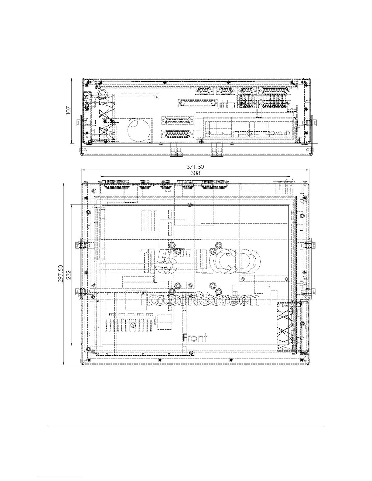
The Touch IPC can be mounted using threads in the sides. Optionally you can order a bracket that
will fit the Rose+Krieger system. Please see page 23 (drawings)
To mount in the side, use a 6 mm screw, metric thread.
The maximum length of thread to go inside the Touch IPC is 15mm.
It is recommended NOT to use larger screws than 6 x 16.
If you use a longer screw, you will damage electronics inside.
Page 4
Touch IPC Technical Manual
Page 2
Electrical installation
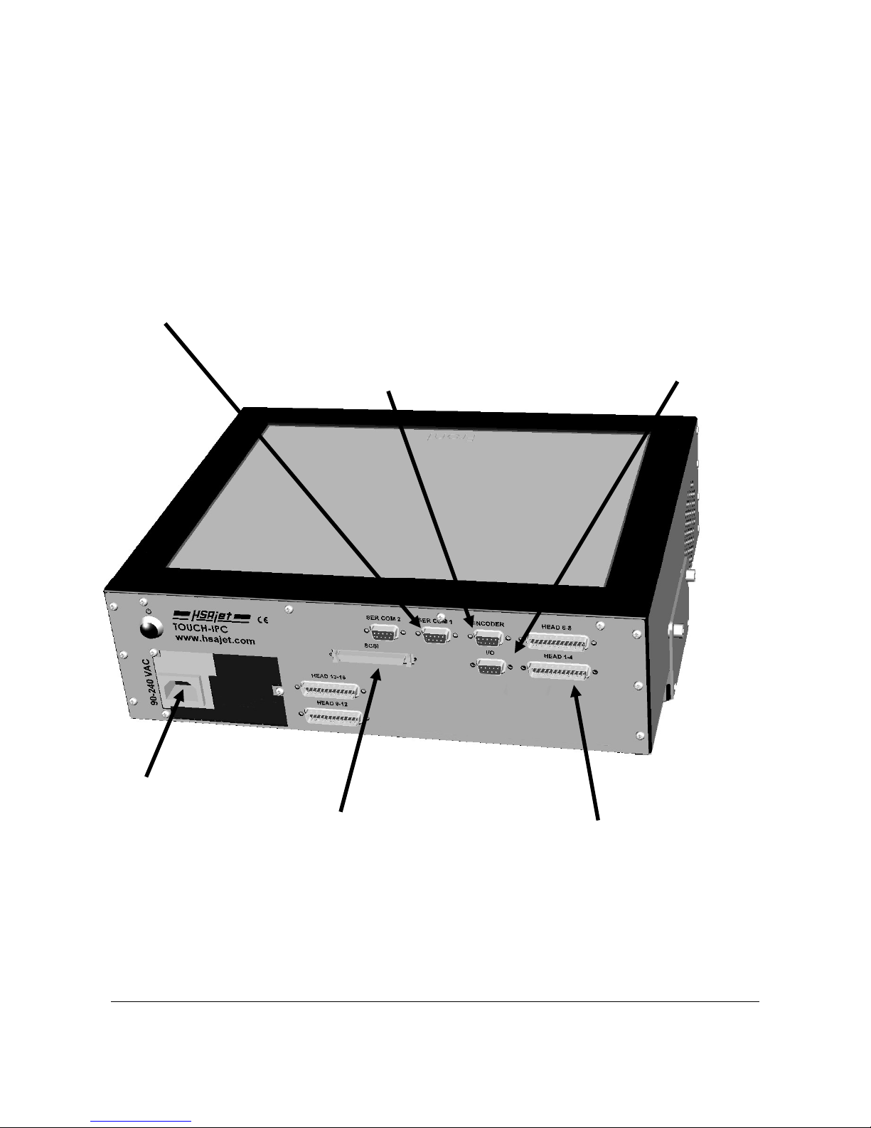
The touch IPC is a standard PC with all the standard connections. In addition to these standard
connections, the Touch IPC has connectors that are used for printer connections and I/O related to
that.
Below is a schematic overview of where you should connect cables to the Touch IPC. Pinouts for
the I/O connectors are found in the back of this guide.
Normal power connector,
90 – 240 V.
Sub-D connectors
Use with one of:
1 x HP head
or
4 x Xaar128 Head
or
1 x XJ500 Head
SCSI connector.
Use with HPHEAD 3 or 4
Do NOT use at same time
as Sub-D connectors
Encoder Connector
use for accurate measurement
of speed. Recommended
to connect encoder during print
I/O connector for start
sensor and also outputs for
low ink
Serial Communication
with Controller Board
Page 5

Touch IPC Technical Manual
Page 3
Capability of the Touch IPC
On the Touch IPC you can connect the following equipment:
HP printers
up to 4 pens. This can be as one of the
following configurations:
On SUB-D Connectors
• 1 .. 4 single pens
• 2 + 2 pens
On SCSI connector
• 1 x 3 pens
• 1 x 4 pens
XaarJet 128 printers Up to 16 XJ128 print engines. This can be
single engine printers that are daisy-chained, or
multiple-engine printers that are on different
connectors.
Each connector will accept up to 4 XJ128
engines.
XaarJet 500 printers Up to 4 XJ500 printers
Notice that you must specify the model of Touch IPC you wish to use. It is not
possible to use the same machine for alle types of printer.
Page 6

Touch IPC Technical Manual
Page 4
System Installation
First time you start your Touch IPC
The TOUCH IPC is supplied with Windows XP pre-installed. Please check that there is an intact
sticker on the side of your machine containing the XP licence.
First time you start your machine, you will be prompted to enter the license key. This will have a
format of 25 characters, in groups of 5 (like A4FKG-C839V-... ).
HS Automatic supplies an OEM version of Windows XP. This means that
Windows has been pre-installed for you, and you do not get a CD or
manual from Microsoft.
For performance reasons, the firewall and automatic update has been
disabled on the TIPC.
It is not recommended that you have direct internet access on a
Touch IPC used in an production environment. The settings below are
for PRINTING need in a factory, NOT for Internet access on a public
terminal. Likewise, there are NOT set up any restrictions for the
default user account.
If you need direct internet access, please consult a guide on how to secure
Windows XP and download Windows update.
Page 7

Touch IPC Technical Manual
Page 5
HS Automatic has configured Windows as follows:
● There is an account “USER” which is loaded by default, and starts INKdraw
● The installation is multi-language-enabled. This means that you freely can choose the
language you wish to see in Windows. There is also support for non-western scripts like
Japanese, Thai, Hebrew and Arab.
● The hard drive will, for efficiency reasons, be split up in 3 partitions:
c C: Main Windows partition
c D: Swap drive for temporary storage
c E: Room for applications / Storage
● INKdraw has been setup with default directories search path
c INK files: {install}\files
e:\inkdraw\files
c Graphics {install}\logo
e:\inkdraw\logo
e:\graphics
c Database {install}\database
e:\inkdraw\database
● There is installed a freeware application “Click-N-Type” that allows you to activate an on-
screen keyboard. Although Microsoft does have this function already, the alternative
keyboard can be re-designed to your own specifications.
Page 8

Touch IPC Technical Manual
Page 6
Customizing the TIPC
There are a number of settings you may change according to how your customer will work. The
typical settings are described below.
Rotate the screen
The monitor driver allows the screen to be rotated. By default, 0 degrees is “connectors UP” while
180 degrees is “connectors DOWN”.
In the lower right part of the screen
there is a yellow icon with the text
”S3”.
Click on this icon with the mouse.
Then select ”Rotation” and the way
you wish to rotate the screen.
You will be asked to calibrate the
screen (simply point to a dot) to
change mouse orientation also.
Calibrate the touch interface
Should the touch interface become inaccurate, you can carry out a manual recalibration. Usually a
“standard” calibration is enough.
Click on the icon ”PM” in the lower
right corner and choose ”Control
Panel”.
Select tab for ”Calibrate” and click
”Standard Calibration”.
Click on the red dots as requested.
It is recommended to use a stylus
during this process, for improved
accuracy.
In the same menu, there are a number of settings / features related to the touch interface. They will
not be described here, but are quite self-explanatory.
Page 9

Touch IPC Technical Manual
Page 7
International Support
By default, English (US) Windows XP is installed on your Touch IPC.
When you wish to customize the Touch IPC for use in a non-English speaking environment, there
are 5 points you should consider changing. These are:
● The user interface of Windows itself (menus, dialog boxes etc)
● The default display for dates, month names etc
● The input language (what character set you mainly use)
● The keyboard layout(s).
● The menus in INKdraw (not covered here, please see INKdraw manual)
Change the Windows user interface language
As part of the Windows XP installation, HS Automatic has installed a number of user interface
languages. This allows every user on the PC to see Windows in their own, local language. Notice
that the language settings of Windows can be done per user. So you can have users that have
French while others have German – etc.
HS Automatic installs the following languages by default:
● English
● Danish
● Czech
● Russian
● Greek
● Hungarian
● Polish
● Portugese
● Turkish
● French
● German
● Japanese
● Arab
● Dutch
● Italian
● Spanish
If you need support for other languages / language groups, please contact HS Automatic. It
may be possible to install your language also.
Page 10
Touch IPC Technical Manual
Page 8
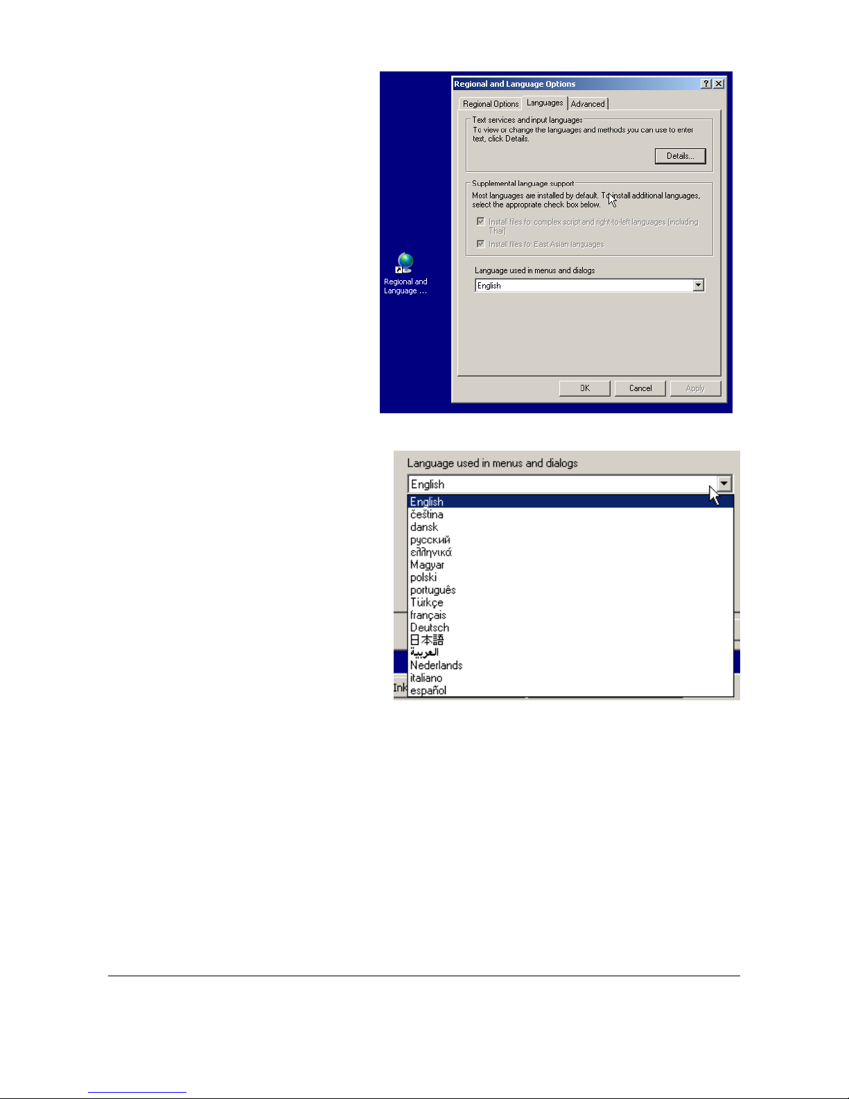
To change the language, select
”Regional and Languages” icon
located on the desktop or from the
Control Panel.
The language setting for the desktop
and Windows in General is in the
second tab ”Languages”, at the
bottom ”Menus and Dialogs”.
Choose any language from the list,
this will be the default Windows
language for this user.
Notice that you must log out and log
in again to activate the new
language.
Page 11
Touch IPC Technical Manual
Page 9
Changing your local language defaults
Although Windows has now been configured to your language of choice you must still tell Windows
what your locale is. A locale defines all the standards for your country, such as
● What month names and days names are
● How to display and format numbers
● How a “short” and “long” date is printed
It is important to know that
1. A locale is independent of your setting in “menus and dialogs” above
2. INKdraw is using the settings from the locale to display date and time.
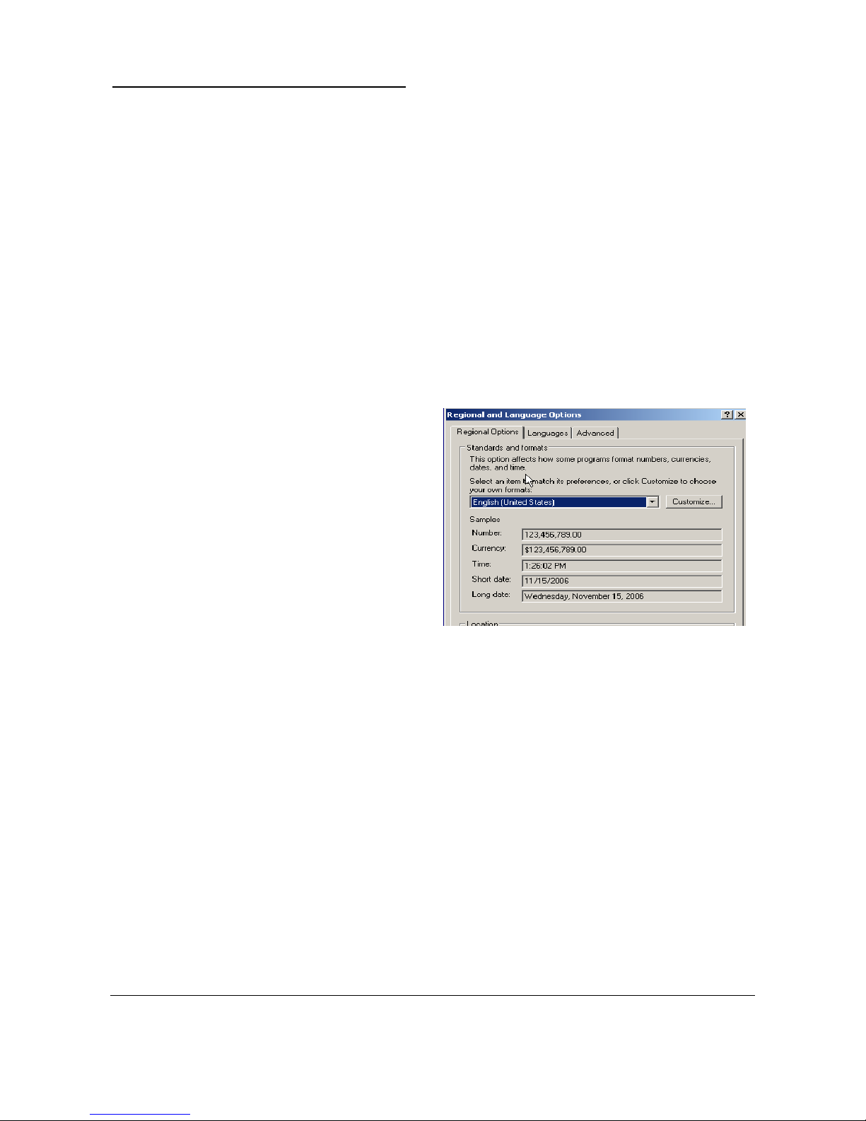
Locale (Standards and formats) is
set in the first tab. You can choose a
pre-defined region or customize the
existing.
The ”Location” below in this window
is only used in Microsoft services
and has no relevance for the TIPC.
Page 12
Touch IPC Technical Manual
Page 10
Changing input language for INKdraw
If you wish to work with INKdraw primarily in your local, non-western, language (such as Japanese,
Hebrew, Thai, Arab,...) it is important that you change the Input Language to the one you use.
This is needed because INKdraw is not Unicode-Compatible, and is a requirement to edit and use
databases in non-western languages.
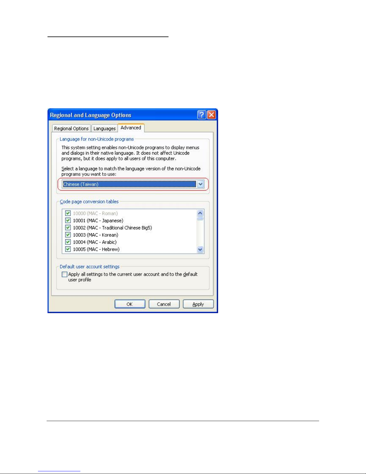
Do so by – again – going into settings for regional and language.
On the final tab “Advanced” you can
select “Language for non-Unicode
programs”.
Choose your input format here.
Windows may ask you if you wish to
use the files already installed, just
answer “Yes” to this.
Page 13
Touch IPC Technical Manual
Page 11
Keyboard Layout / Input method
Finally, you can add one or more keyboard layouts (input Method).
A keyboard layout decides which characters are input from your keyboard and how. Adding other
than your default language here may allow you to input characters that are not otherwise available
from your keyboard.
HS Automatic has, as part of the Touch IPC installation, included support for non-western
languages. If you select one of these, you will be able to use the Microsoft on-screen keyboard
(Microsoft Input Method), by which you can type f.ex. japanese.
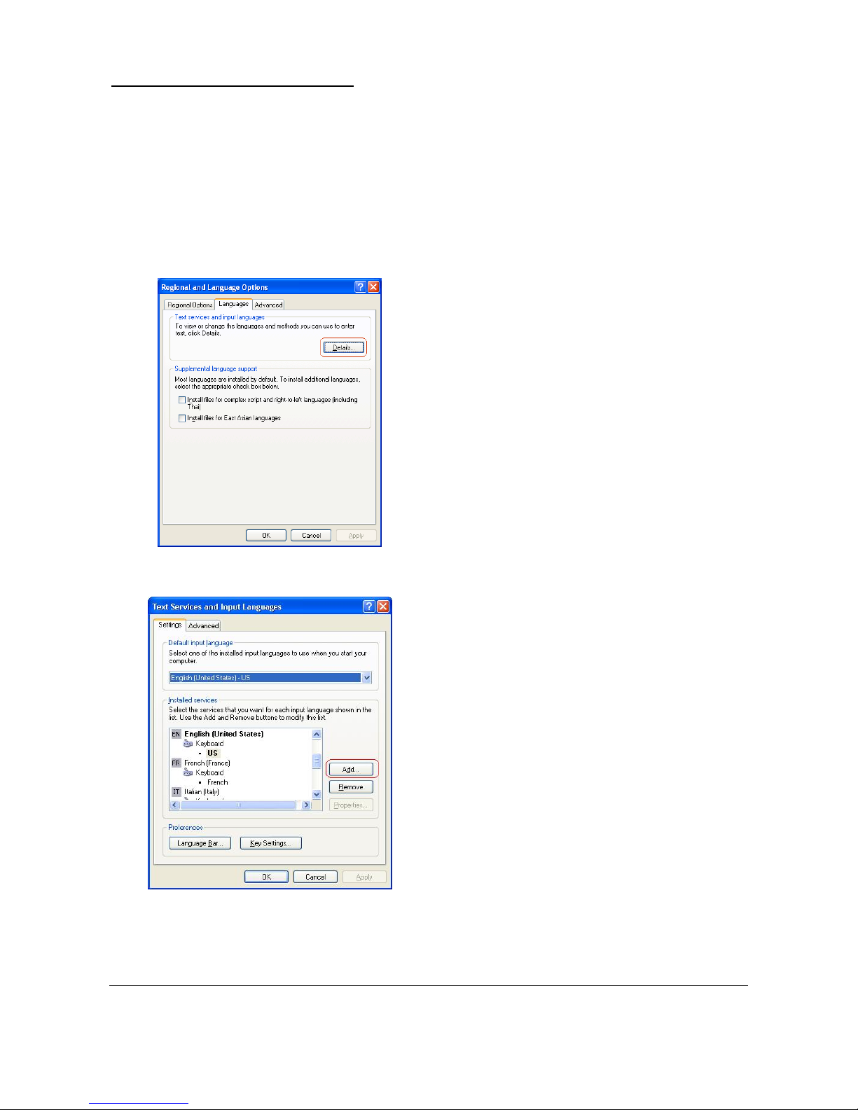
To change the keyboard click “Details” in the second
tab “Languages”.
Under Installed Services, click "Add..."
In the illustration here, there is already support for
● US English (default)
● French / France
● Italian / Italy
Page 14
Touch IPC Technical Manual
Page 12
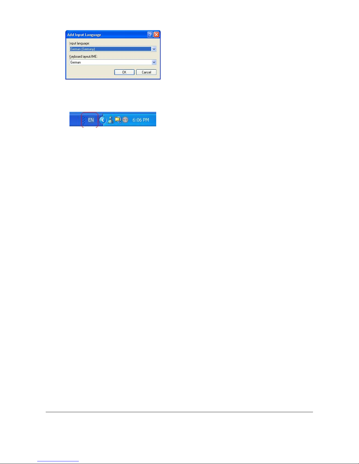
In the Add Input Language dialog box, click the input
language and keyboard layout or Input Method
Editor (IME) you want to add.
Here, a German language with German keyboard is
added.
You should now see a language indicator in the
System Tray (located at bottom right hand corner of
the desktop by default)
NOTE: You can switch between different input methods by pressing the left Alt + Shift keys or the
right Alt + Shift keys. You can also have the language indicator appear as a small bar on your
screen.
Page 15
Touch IPC Technical Manual
Page 13
Service
Take-apart guide and what's inside
Typically it is not necessary to open your Touch IPC, as there are very few user-serviceable parts
inside.
If you need to, please consult HS Automatic before you open your unit.
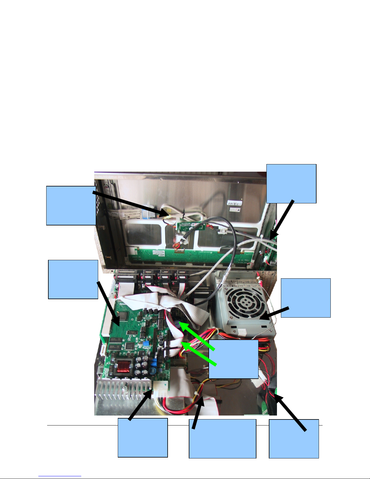
The Touch IPC should be opened by removing the screws on bottom plate, which wraps around
the connector side. Carefully open the unit with the monitor upwards and connectors towards
yourself. The unit opens as if there was a hinge. Take great care not to remove the monitor from
the main unit, as there are cables going from the main board to the monitor.
CB Board
5/12 V connection
to CB board
Cable to hard drive
Internal 2nd drive
may connect here.
Connection to
Touch Panel
Back Light
for monitor
(High Voltage!)
Power Supply
Chassis Fan
Motherboard
Memory
Page 16
Touch IPC Technical Manual
Page 14
Serviceable parts (fuses etc)
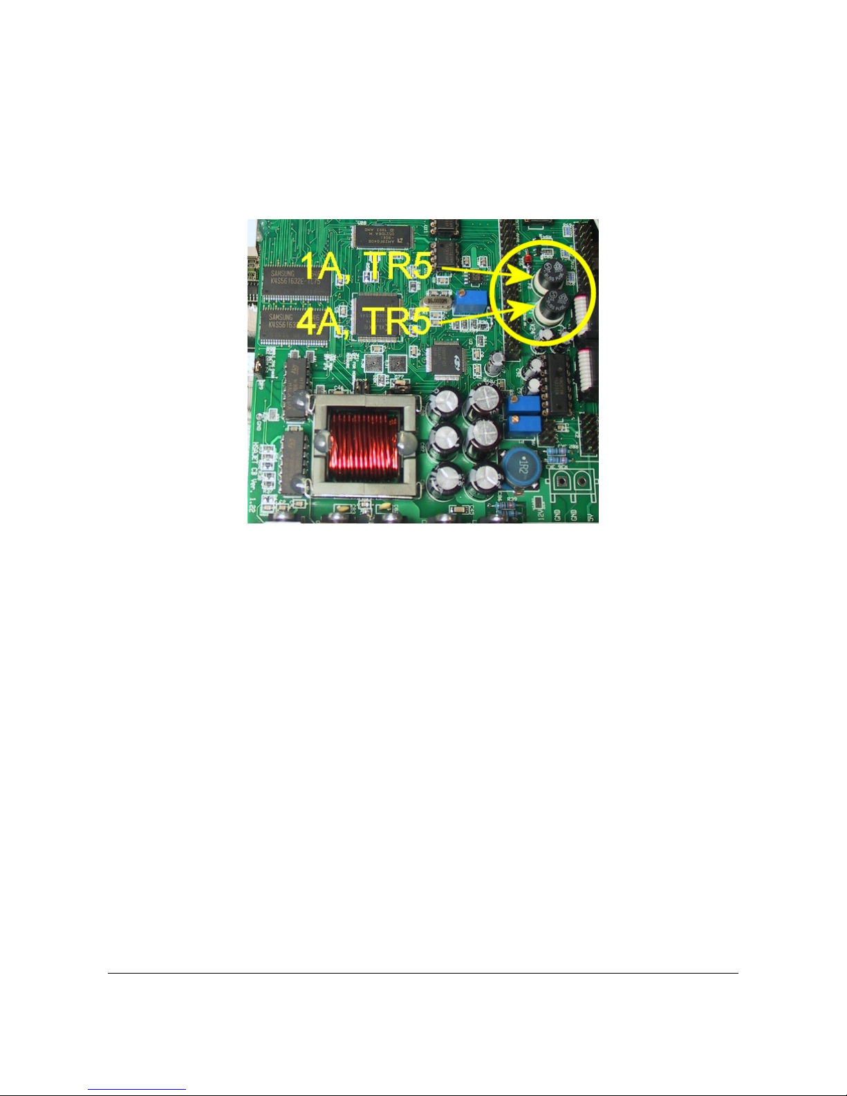
There are 2 fuses located on the CB board itself. They are type TR5 (round with 2 pins facing
down). You need 1A and 4A fuses, placed as illustrated below.
Page 17

Touch IPC Technical Manual
Page 15
Reference Section
Default (working) BIOS settings
BIOS settings are the basic settings for the PC. The settings below are the default settings for a
Touch IPC, as supplied from HS Automatic. Normally you should not have to change these
Before you begin you have to connect a PS/2 keyboard and a VGA monitor, you cannot
perform this operation without! (as LCD screen will be inactive without bios settings)
Enter the BIOS editor:
Turn on your IPC by pressing the red button on the front.
Immediately press the delete
key on your keyboard, maybe multiple
times.
Wait until the BIOS editor is loaded.
Reset the BIOS: Select the option: LOAD DEFAULTS
And press Y and enter to approve.
From the factory, the BIOS has been configured to HSA values.
If you need to change boot order, you can do that now.
Close the BIOS editor Move the cursor to SAVE AND EXIT SETUP and press enter
Press Y and enter to save the new settings.
Page 18
Touch IPC Technical Manual
Page 16
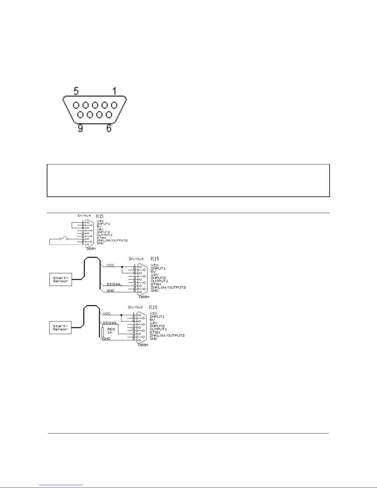
Start sensor connections
As a start sensor, you can use a simple switch, or a photo cell.
PIN........................................................... DESCRIPTION
1............................................................... V I/O
2............................................................... 5 V
3............................................................... IN 2
4............................................................... START
5............................................................... GND
6............................................................... IN 1
7............................................................... 12 V
8............................................................... OUT 1
9............................................................... OUT 2
For both 5V and 12V:
Iout
max
= 1A
Using a simple mechanical switch.
Loop pins 1-2 and connect the switch between
pins 4 and 5.
5 Volt NPN / PUSH/PULL sensor.
VCC to pins 1,2
Signal to pin 4
GND to pin 5
5 Volt PNP sensor.
VCC to pins 1,2
Signal to pin 4
GND to pin 5
1 K resistor between
pin 4 and 5
Page 19
Touch IPC Technical Manual
Page 17
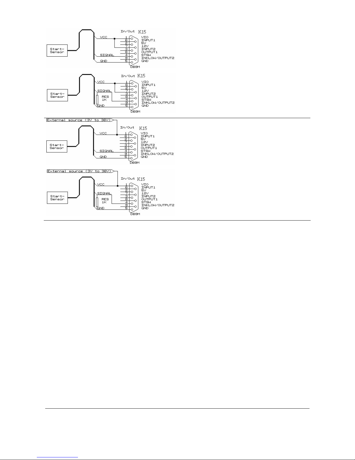
12 Volt NPN / PUSH/PULL
VCC to pins 1,7
Signal to pin 4
GND to pin 5
12 Volt PNP sensor.
VCC to pins 1,7
Signal to pin 4
GND to pin 5
1 K resistor between pin 4 and 5
External power source, +3-36V, using NPN /
PUSH/PULL sensor
VCC to pin 1
Signal to pin 4
GND to pin 5
External power source, +3-36V, using PNP
sensor
VCC to pin 1
Signal to pin 4
GND to pin 5
1K resistor between 4 and 5.
Page 20
Touch IPC Technical Manual
Page 18
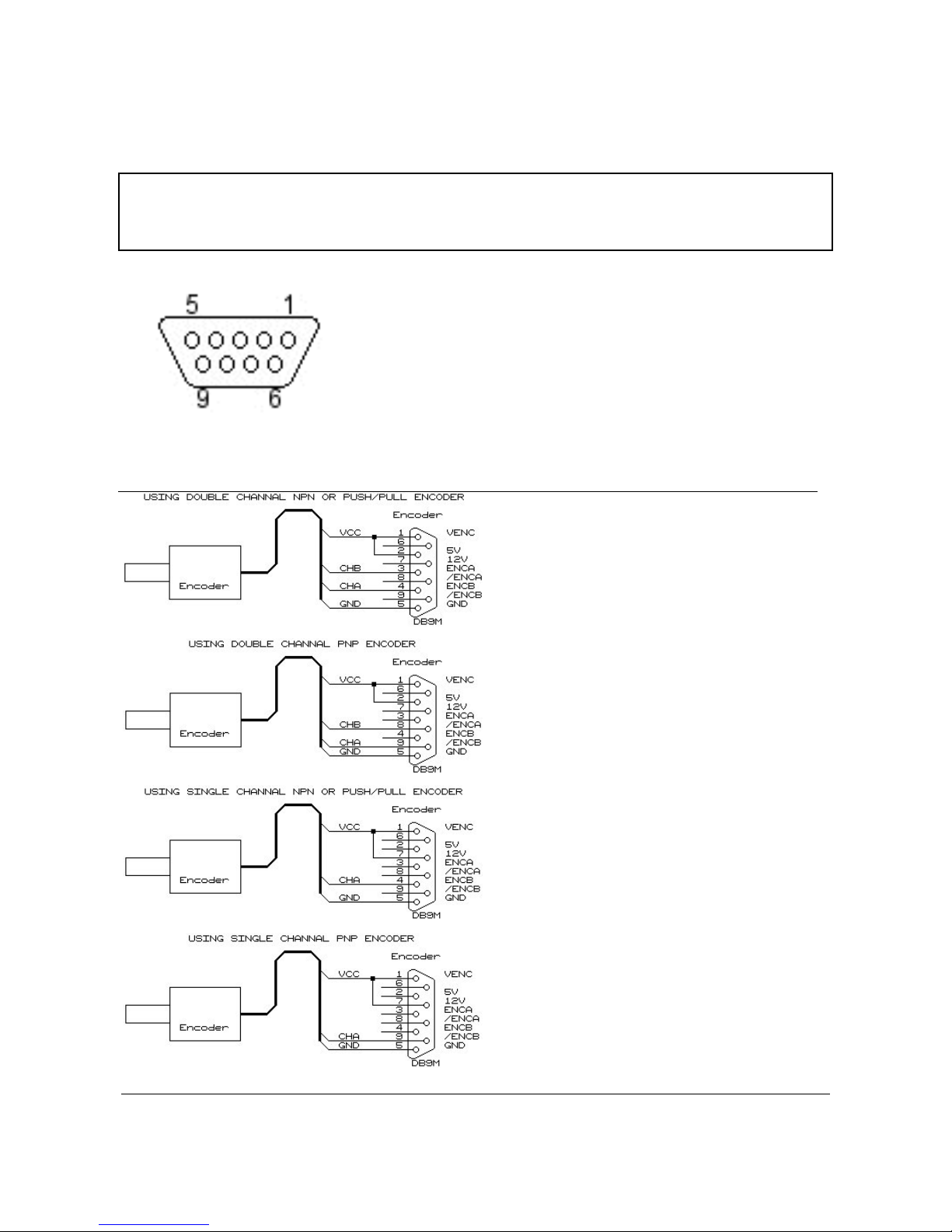
Encoder connections
For the encoder, you can use either a single or double channel. If you have both channels
connected, you need to activate “Quadrature” in the software, and divide distance / pulses by 4.
For both 5V and 12V:
Iout
max
= 1A
PIN........................................................... DESCRIPTION
1............................................................... V ENC
2............................................................... 5 V
3............................................................... ENC A
4............................................................... ENC B
5............................................................... GND
6............................................................... INK LEVEL (not used)
7............................................................... 12 V
8............................................................... ENC A (inv.)
9............................................................... ENC B (inv.)
5 VOLT encoder double channel
NPN / PUSH/PULL encoder
5 VOLT encoder double channel
PNP encoder
12 Volt encoder single channel
NPN/ PUSH/PULL encoder
12 Volt encoder single channel
PNP encoder
Page 21
Touch IPC Technical Manual
Page 19
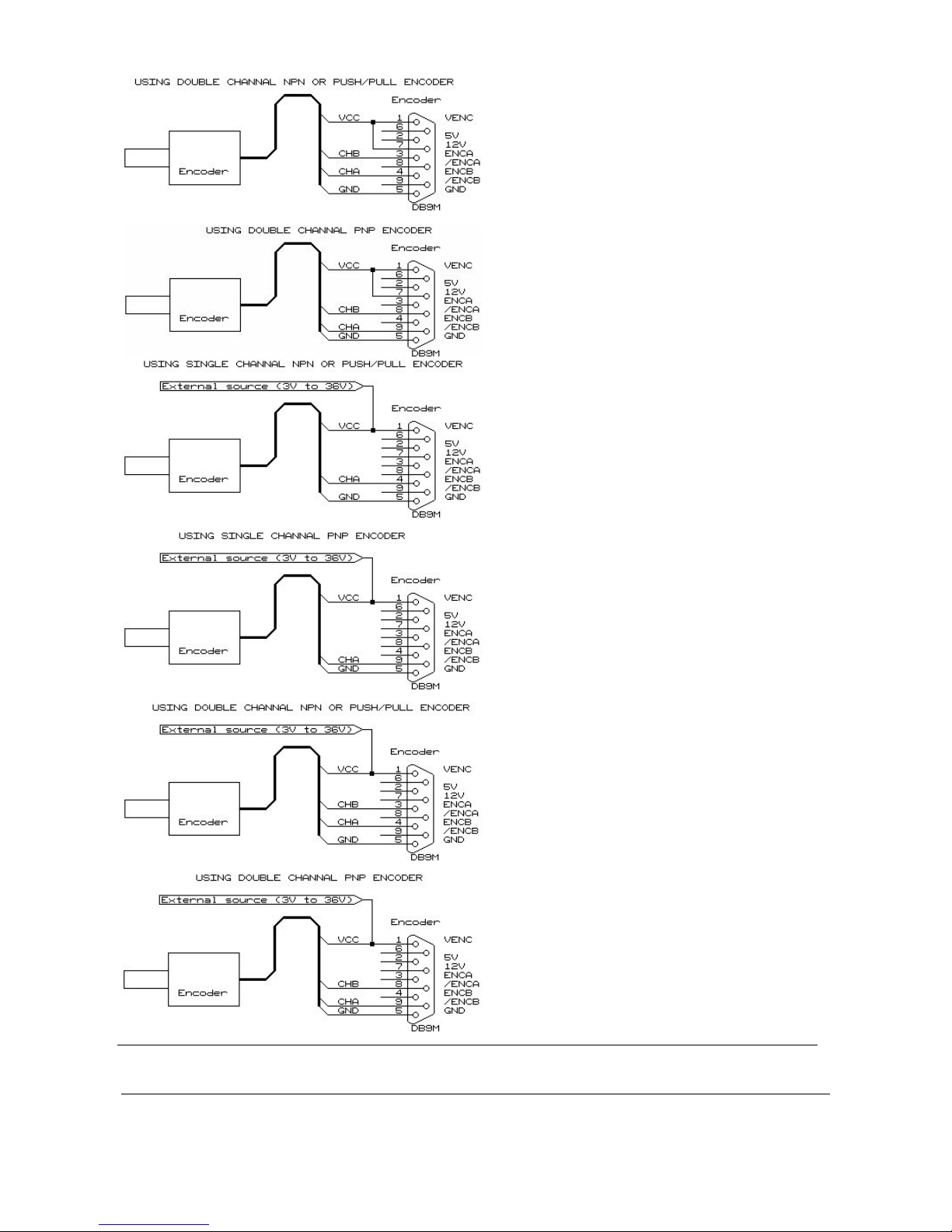
12 Volt encoder double channel
NPN / PUSH/PULL encoder
12 Volt encoder double channel
PNP encoder
External power source, 3-36V, encoder
single channel
NPN/ PUSH/PULL encoder
External power source, 3-36V, encoder
single channel
PNP encoder
External power source, 3-36V, encoder
double channel
NPN / PUSH/PULL encoder
External power source, 3-36V, encoder
double channel
PNP encoder
Page 22
Touch IPC Technical Manual
Page 20
Output Connections
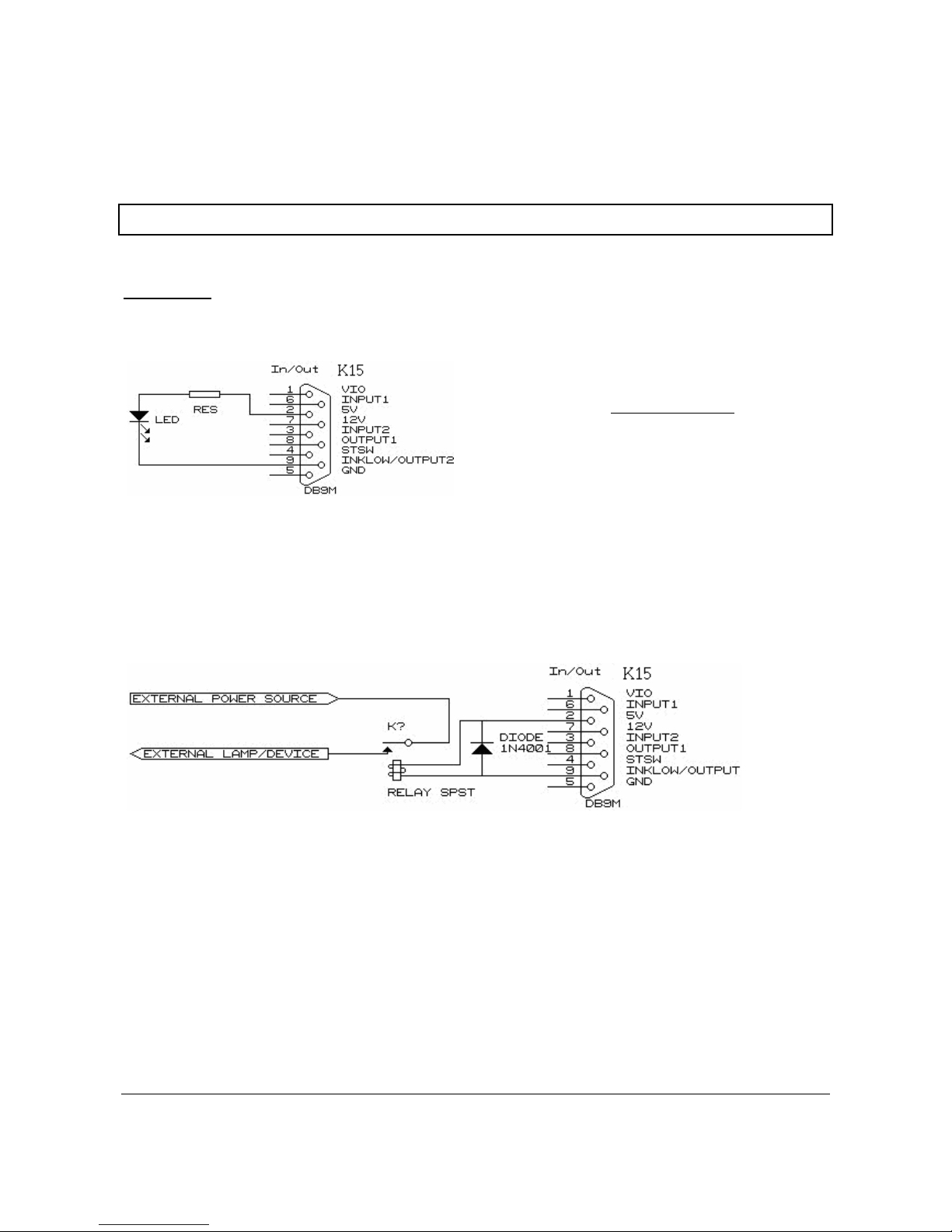
On the Touch IPC there are 2 different outputs that can be used for detection of when a message
has been printed, and to give an alarm for low ink.
Notice that Iout
max
= 400mA
OUTPUT1:
This is always print message signal. The LED or relay will be active every time the start sensor is
activated, until the message has been printed.
Connecting an LED
Led=
5V−
L
EDvoltage
LEDcurrent
Connecting a RELAY
Schematic (for 5V relay), for Signal lamp/sound
device:
Page 23
Touch IPC Technical Manual
Page 21
OUTPUT2 :
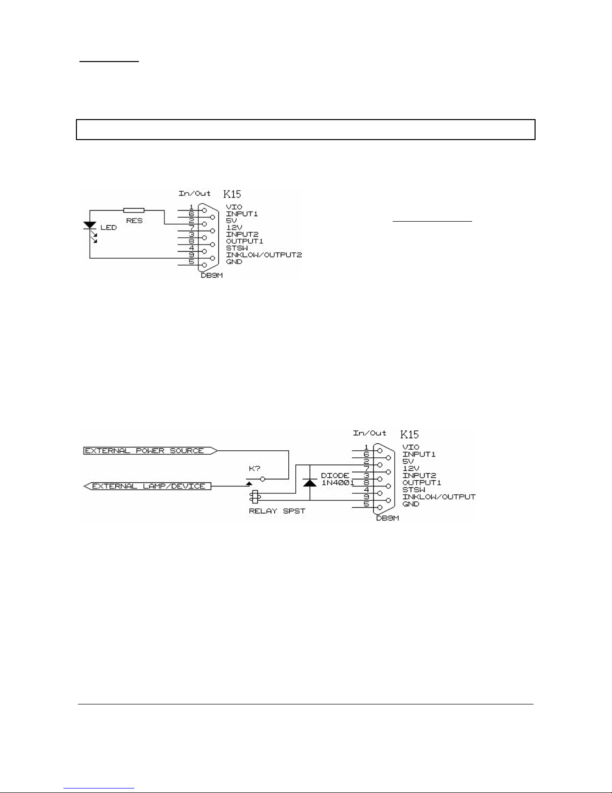
This is used to get the low ink warning. On Xaar printers, you will see a signal on the printer as
well, on HP printers you can see on the monitor which cartridge is empty.
Notice: Iout max = 400mA
Connecting an LED
Led=
5V−
L
EDvoltage
LEDcurrent
Depending on the LED used the LEDcurrent
usually is:
For small surface mount LEDs: 5-10mA.
For most Leaded LEDs: 10-25mA.
Connecting a RELAY
Schematic (for 5V relay), for Signal lamp/sound
device.
For 5V relays: Between pin 2 and pin 9.
For 12V relays: Between pin 7 and pin 9.
Page 24

Touch IPC Technical Manual
Page 22
Exact Machine Reference
Motherboard
Model: VIA ENDAT 3405M
Supplier: Unicorn Computers, Taiwan
North Bridge VT8603
Processor
VIA Niehemiah
1 Ghz
Memory
512 MB DDR 400
Graphics
S3 graphics Twister, On-Board
Chip: S3-VIA Twister(TM) 380-381
Chipset PN133 / VT8603 ProSavage PN133
Chip ID 8D01
Supported AGP 2.0, 4X speed, 66 MHz PCI
Hard Drive
Model HITACHI Deskstar 7K160
Reference HDS721680PLA380
Capacity: 80 GB
Interface: SATA
Speed 7200 RPM, up to 3 Gb/Sec transfer rate
Page 25
Touch IPC Technical Manual
Page 23
Drawings
Touch IPC outside drawings, for mounting purposes. All sizes are in mm.
Page 26
Touch IPC Technical Manual
Page 24
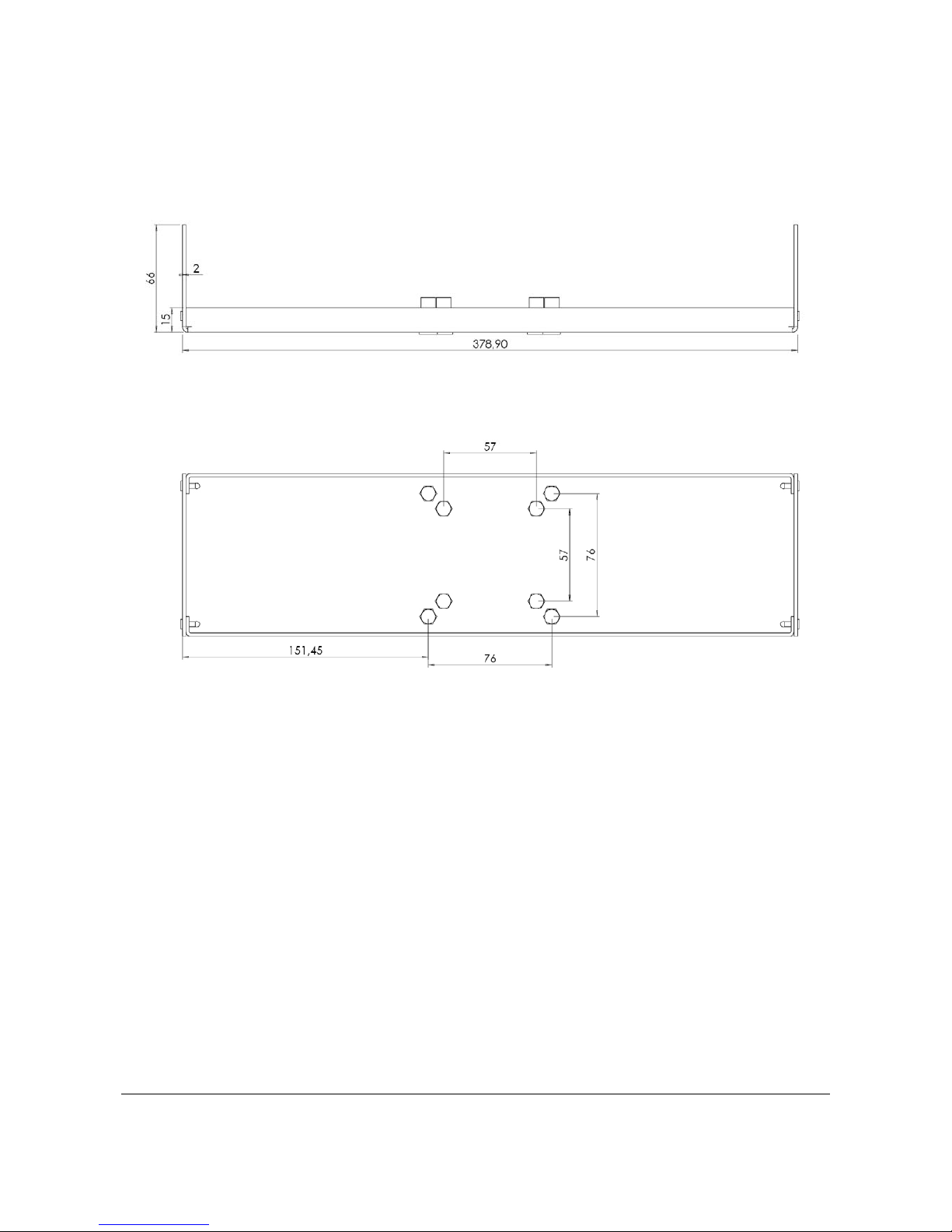
Bracket measurements.
The bracket is optional and can be specified when ordering.
The holes in the bracket are meant to fit Rose+Krieger bracket systems.
 Loading...