

Page 1
INSTALLATION AND
EN FR
OPERATING INSTRUCTIONS
OWNERS MANUAL
SERIES 4200 PNEUMATIC
STOOLS
Page 2

MODEL/SERIAL NUMBER
For your future reference, mark the model number or serial number in the space provided.
QUALITY MANAGEMENT
SYSTEM
REGISTERED TO
ISO 13485
MADE IN AMERICA
Reliance® Medical Products, Inc. • 3535 Kings Mills Road • Mason, Ohio 45040-2303 • 1-800-735-0357 • www.reliance-medical.com
IN-4200 2
Page 3
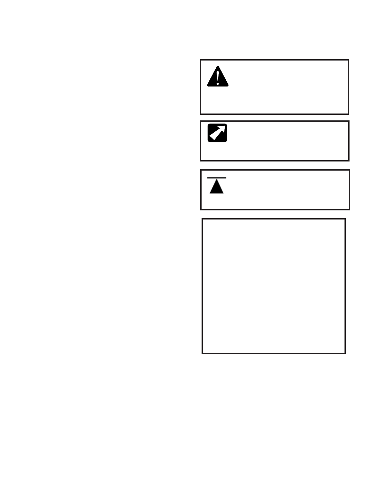
TABLE OF CONTENTS
IMPORTANT INFORMATION........................................3
1. INTRODUCTION.........................................................4
2. INSTALLATION...........................................................4
2.1. Unpacking.......................................................4
2.2. Assembly.........................................................4
3. OPERATING INSTRUCTIONS......................................5
3.1. Seat Height Adjustment...................................5
3.2. Back Rest Adjustment ......................................5
4. Replacement of Parts................................................5
PARTS LIST....................................................................7
CLEANING AND MAINTENANCE........................................13
LIMITED WARRANTY.....................................................14
IMPORTANT INFORMATION
SAFETY SYMBOLS
“DANGER”, “WARNING”, or “CAUTION”
The exclamation point within a triangle is
intended to alert the user to the presence
of important operating and maintenance
(servicing) instructions in this Installation
and Operating Instructions.
“NOTE”
Note indicates points of particular or
additional information.
Safe Working Load
TRANSPORTATION / STORAGE CONDITIONS
Temperature: Operating: 50 to 104º F
10 to 40º C
Storage: -40 to +158º F
-40 to +70º C
Relative Humidity: Operating: 30%RH to 75%RH
without condensation
Storage: 10%RH to 100%RH
including condensation
Atmospheric Pressure
Operating: 700hPa to 1060hPa
Storage: 500hPa to 1060hPa
IN-4200
3
Page 4

1. INTRODUCTION
1.1. This manual contains information applicable
only to the Reliance® Series 4200 Stools. Should
you have a different model, please disregard any
information that does not apply.
1.2. Whenever you see the symbols shown below,
heed their instructions! Always follow safe operating
and maintenance practices.
“WARNING”-
The warning symbol identies
special instructions or procedures which,
if not correctly followed, could result in
personal injury.
2. INSTALLATION
2.1. Unpacking
2.1.1. Open the shipping carton carefully and record
any shipping damage to the carton or to the contents.
2.1.2. Remove all contents from the shipping carton.
Note that Model 4246 stool is shipped with the back
support mounted, but inverted.
“WARNING” -
Never place a damaged
stool into service. Contact your Reliance®
Distributor.
“VERTISSANT“-
Le symbole d’avertissement
identie les instructions spéciales ou les
procédures qui, sinon correctement suivi,
pourraient avoir comme conséquence des
blessures.
“CAUTION”-
This caution symbol identies
special instructions or procedures which, if
not strictly observed, could result in damage
to or destruction of equipment.
“ATTENTION“ - ce symbole d’attention
identie les instructions spéciales ou les
procédures aux lesquelles, sinon strictement
observés, pourrait avoir comme conséquence
les dommages ou la destruction de
l’équipement.
“NOTE”-
Note indicates points of particular
or additional information.
“NOTE” -
la note indique des remarques
d’information particulière ou supplémentaire.
“AVERTISSANT“ -
Ne placez jamais un
tabouret endommagé en service. Entrez
en contact avec votre distributeur de
Reliance®.
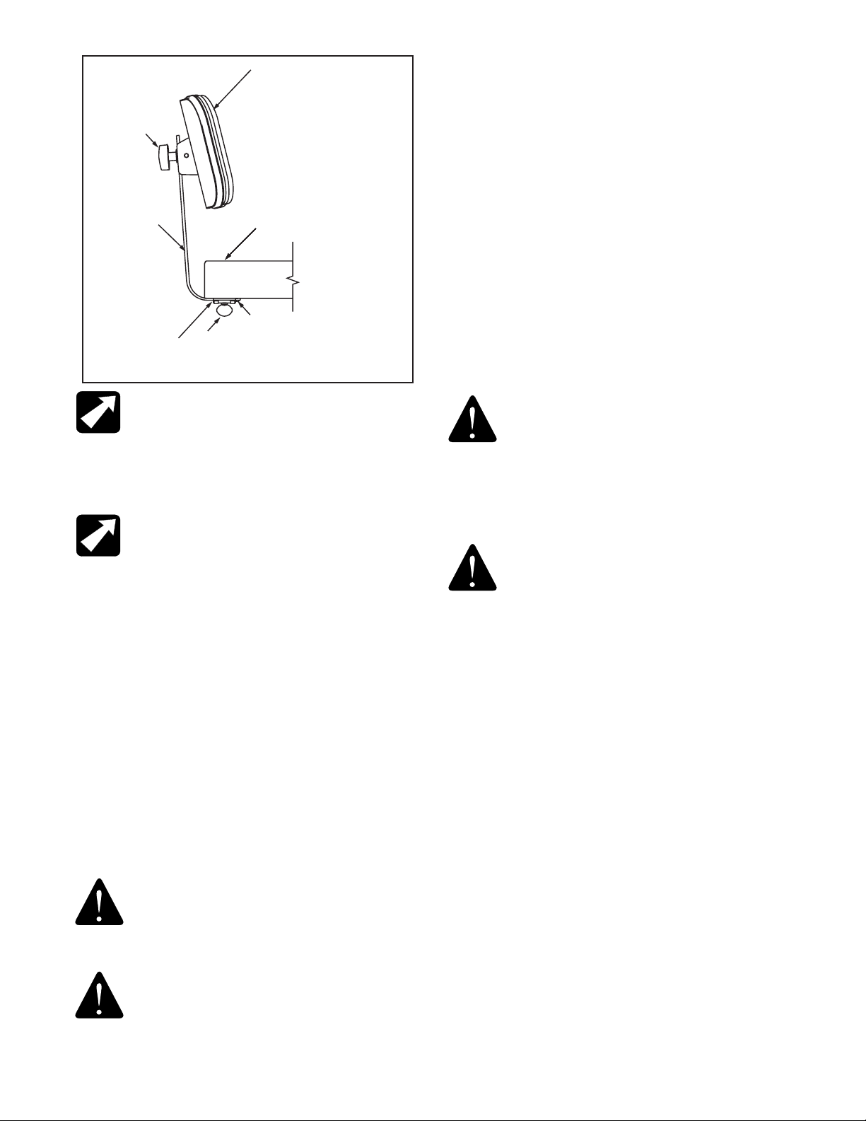
2.2. Assembly
2.2.1. lf the Model 4240 was ordered, there is no
assembly required. To assemble Model 4246, loosen
the thumbscrew (ltem 5, Figure 1) and remove the
back support (ltem 3, Figure 1). Re-install the back
support in its correct (upright) position and tighten
the thumbscrew.
2.2.2. Remove the upholstered back assembly (ltem
1 , Figure 1) from the smaller box and remove the
handwheel (ltem 2, Figure 1) and two washers (Item
6, & Item 7, Figure 4). lnsert the stud on the upholstered back through the slot in the back support and
the washers on the same side as the handwheel.
2.2.2.1. Hold the upholstered back in the correct
position and tighten the handwheel.
1.3 Should your product not perform properly, or if
you have any questions concerning the use and care
of any Reliance® product, contact the Reliance®
Distributor where you purchased this product or
contact the Technical Service Department, Reliance®
Medical Products, Inc., 3535 Kings Mills Road,
Mason, Ohio 45040-2303, or call (800) 735-0358.
“NOTE”-
Always have the model number and
serial number available before contacting
Reliance® or your authorized Reliance®
Distributor.
“NOTE”-
Ayez toujours le numéro et le
numéro de série de type disponibles avant
Reliance® entrant en contact ou votre
distributeur autorisé de Reliance®.
“NOTE”- When installing the upholstered back,
make sure the narrow portion of the back is
down, or closest to the upholstered seat.
“NOTE”- En installant tapissé en arrière,
assurez-vous que la partie étroite du dos est
en baisse, ou le plus proche du siège tapissé.
IN-4200 4
Page 5
1
3.2. Back Rest Adjustment
2
3
5
4
STOOL
SEAT
STOP SCREW
FIGURE 1
“NOTE”- After support bar has been
inserted into back support per the assembly
instructions (section 2.2), insert stop screw
into threaded hole in end of support bar. The
#10-24 x ¼ Round Head Machine Screw (Part
Number 2037299) is shipped in the parts bag.
“NOTE”- Après que la barre de soutien ait été
insérée dans l’appui arrière par instructions
d’assemblée (section 2.2), insérez la vis d’arrêt
dans le trou leté dans l’extrémité de la barre de
soutien. Les #10-24 la vis principale que ronde de
machine de ¼ de X (numéro de la pièce 2037299)
est embarquée dans les pièces mettent en sac.
3. OPERATING INSTRUCTIONS
3.1. Seat Height Adjustment
3.1.1. A metered gas spring device provides for controlled
raising of the stool seat without load and controlled
lowering under load.
3.1.2 To raise the seat, support the body weight from the
oor and raise the lock handle lever located under the
seat. Allow the seat to rise to the desired position and
release the handle.
3.2.1. The back rest typical of Model 4246 can be
adjusted vertically and horizontally.
3.5.2. To adjust the back rest vertically, loosen the
black handwheel, (ltem 2, Figure 1), move the back
rest to the desired position and tighten the handwheel.
3.2.3. To adjust the back rest horizontally, loosen the
thumbscrew (ltem 5, Figure 1), move the support bar,
Item 3, as desired and tighten the thumb screw
securely.
“WARNING”- The foot rest ring is
intended for lightweight foot support only
and is not intended for use as a step/
weight bearing support. lf repositioning
of the body is needed while seated, you
must insure both feet are rmly placed
on the oor before shifting your weight.
“VERTISSANT“-
l’anneau de repos
de pied est prévu pour l’appui léger de
pied seulement et n’est pas prévu pour
l’usage comme support de roulement
d’étape/poids. le replacement de LF du
corps est nécessaire tandis que posé,
vous doit assurer les deux pieds sont
fermement placés sur le plancher avant
de décaler votre poids.
4. Replacement of Parts
4.1. When ordering replacement parts, please specify
the model number of the stool and the proper part
number from the following gures.
4.2. When ordering upholstered items, please specify
color.
“CAUTION”- When raising the seat, ensure
that the stool remains clear of any furniture or
equipment. Otherwise, the resulting raising force
may damage the furniture, equipment or stool.
“ATTENTION“ -
vous que le tabouret reste dégagé de n’importe
quels meubles ou équipement. Autrement, la
force augmentante résultante peut endommager
les meubles, l’équipement ou le tabouret.
IN-4200
En soulevant le siège, assurez-
5
Page 6

(PAGE LEFT BLANK INTENTIONALLY)
IN-4200 6
Page 7

PARTS LIST
RELIANCE® MODEL 4200
SERIES STOOL
“Note” : When ordering parts, please:
1. Advise dealer or factory of model and serial number of stool. These numbers are on the
label that is located on the seat bottom.
2. Upholstered parts have an asterisk(*) behind the part description.
“Note” : Lors d’une commande de pièces, s’il vous plaît :
1.Informez le distributeur ou l’usine du modèle et du numéro de série des selles. Ces numéros
sont sur l’étiquette qui est située sur le bas de portée.
2. Les pièces tapissées ont un astérisque (*) derrière la description de pièce.
Should your stool not perform properly, or if replacement parts are
needed, contact the Reliance® Distributor, where you purchased this
product or contact the Technical Service Department, Reliance® Medical
Products, Inc., 3535 Kings Mills Road, Mason, Ohio 45040-2303, or call
(800) 735-0358.
IN-4200
7
Page 8

PART N O. DESC RIPTION
ITEM
0478699 BALL CASTER
1570999 GLIDE - 2-5/16 TALL
0613399 CASTER-2-1/2
1
0637199 CONDUCTIVE CASTER
1565399 CASTER - 2" DIA. TWIN WHEEL
2
2037399 BASE, STOOL 4200 SERIES, 50MM
0301599 SCREW, PH #8 AB X 1/2 SELF TAP, PHIL
3
4
1664173*
5
2735799 SEAT MOUNT ASS'Y
6
0728299 LOCKWASHER - 1/4
0713499 R.H.M.S. 1/4-20 x 1-1/4
7
8
2037499 COLUMN ASS'Y -4200 SERIES, 50MM
9
2336399 FOOTREST, RING
10
1565499 CAP, BASE - SNAP ON
SEAT, UPHOLSTERED
TABLE FIGURE 2
* WHEN ORDERING PLEASE SPECIFY UPHOLSTERY COLOR
NOTE: TO CONVERT A 4240 STOOL TO 4246 USE KIT NO.
1443673
IN-4200 8
Page 9

4
5
6
3
7
8
2
10
RELIANCE®
MODEL 4240 PNEUMATIC STOOL, AND
BASE PARTS
FIGURE 2
9
1
IN-4200
9
Page 10

ITEM
PART NO. DESC RIPTION
2
3
4
5
2037399 BASE, STOOL 4200 SERIES, 50MM
0301599 SCREW, PH #8 AB X 1/2 SELF TAP, PHIL
2735799 SEAT MOUNT ASS'Y
6
0728299 LOCKWASHER - 1/4
7
0713499
R.H.M.S. 1/4-20 x 1-1/4
8
9
2336399 FOOTREST, RING
10
1565499 CAP, BASE - SNAP ON
2343673* SECRETARY BACKREST ASSEMBLY
2037499 COLUMN ASS'Y -4200 SERIES, 50MM
SEAT, UPHOLSTERED
1664173*
11
12
2343085 BACK SUPPORT
13
1288799 BACK SUPPORT MOUNT
0781699 THUMBSCREW, 3/8-24
14
1
1570999 GLIDE - 2-5/16 TALL
1565399 CASTER - 2" DIA. TWIN WHEEL
0613399 CASTER-2-1/2
0637199 CONDUCTIVE CASTER
0478699 BALL CASTER
0292799 R.H.M.S., 1/4-20 X 1.00 - ZINC
15
3155499 Spacer, Back Support Mount
16
TABLE FIGURE 3
* WHEN ORDERING PLEASE SPECIFY UPHOLSTERY COLOR
IN-4200 10
Page 11

11 SEE FIGURE 5
4
12
13
16
6
14
5
6
3
7
8
9
2
IN-4200
10
1
RELIANCE®
MODEL 4246 PNEUMATIC STOOL, AND
BASE PARTS
FIGURE 3
11
Page 12

2
ITEM
PART NO. DESCRIPTION
1
2
3
4
5
6
7
8
9
1987599 Knob, 5 Lobe, 3/8-16 Insert
2342999 Washer, 3/8 Nylon
0306799 Elevator Bolt
1408099 Hinge & Pivot
1407999 Spring
0717799 FHMS 10-24 x 1.00 Phil
1289073* UPH. Back
1408199 Hinge Cover
Washer, 3/8, Black Oxide2342899
1
9
4
3
RELIANCE®
SECRETARY BACKREST ASSEMBLY
FIGURE 4
8
6
7
5
TABLE FIGURE 4
* WHEN ORDERING PLEASE SPECIFY UPHOLSTERY COLOR
IN-420012
Page 13

CLEANING AND MAINTENANCE
Cleaning the Upholstery
When cleaning upholstery, it is suggested that you use all
recommended commercial cleaning agents in an inconspicuous spot to check for potential damage to the upholstery
material before applying to the entire area to be cleaned.
Day to Day soil:
Remove ordinary dirt and smudges with a mild soap and
warm water solution. Dry with a soft, lint-free cloth or towel.
For more difcult stains, use of a stronger detergent is
recommended; however, follow the detergent manufacturer’s
instructions closely.
Disinfecting Material:
In order to disinfect, use a 1:9 solution of bleach and water
(1 part bleach to 9 parts water). Wipe surface with damp
cloth then rinse with water immediately, using a damp cloth.
Special cleaning problems:
The following methods are recommended to clean stains
on PreFixx-protected vinyl upholstery. Most stains will be
removed when these cleaning agents are used in the following order.
Type 1 Cleaners: Nonabrasive household cleaners to be
used with water and a soft cloth.
“ATTENTION” - Ces dissolvants sont
hautement inflammables. Prenez le soin
approprié dans le nettoyage et informez le
personnel dans la zone du danger. Usezvous les gants en caoutchouc pendant toute
l’activité de nettoyage. Faites attention en
nettoyant autour des boutons, en piquant et
panneau en bois ou autre décoratif, puisque
ces dissolvants pourraient sérieusement
endommager de telles zones.
Cleaning Painted Surfaces
The painted metal surfaces are covered in durable, powdercoated paint which is resistant to scratching and scufng.
It may be cleaned with a clean cloth dampened with mild,
soapy water or equivalent household product that uses spray
application.
Recommended Infection Control Products
The disinfectant/cleaner products that we have tested and
recommend for our upholstery, painted items and plastic
covers are as follows.
• Formula 409®~ All-Purpose Spray Cleaner
• Fantastik® Spray Cleaner
• Other similar household cleaners and bleaches
Type 2 Cleaners: Solvent-type cleaner to be liberally
applied with a soft cloth. Dry area with another cloth, rinse
with clean water and dry.
• Rubbing alcohol (isopropyl alcohol)
• Lighter uid (naptha)
Type 3 Cleaners: Strong, active solvent cleaners such
as nail polish remover (acetone/water) to be applied with
a soft cloth. Stain should be removed with less than six (6)
rubs; if stain persists after six rubs, contact manufacturer.
Dry area with another cloth, rinse with clean water and dry.
“CAUTION”- These solvents are highly
flammable. Exercise proper care in cleaning
and notify personnel in area of danger. Wear
rubber gloves during all cleaning activity. Use
caution in cleaning around buttons, stitching
and wooden or other decorative trim, since
these solvents could seriously damage such
areas.
• Cavicide® Hospital Disinfectant
• Precise® Hospital Foam Cleaner Disinfectant
“CAUTION” - Follow manufacturer’s directions
for concentration and application of disinfecting
material. Avoid prolonged application of any
disinfectant/cleaner products, because they
may cause staining of upholstery material.
“ATTENTION “ - Suivez les sens du constructeur
pour la concentration et l’application de
la désinfection produit. Évitez l’application
prolongée de tous les produits désinfectants/
plus propres, parce qu’elles peuvent causer la
souillure du produit de capitonnage.
IN-4200
13
Page 14

LIMITED WARRANTY
The Reliance® product must be used only for the purposes and in the manner described in the literature
distributed with the product. The products are warranted against defective materials and workmanship for the
period set forth in the warranty provided with each product. Products or parts thereof will be repaired or replaced
as required at Reliance® Medical Products, Inc. Such repair or replacement shall be the sole remedy under
this warranty. This warranty extends only to the original purchaser from an authorized Reliance® dealer and is
subject to the following conditions:
1. The warranty card must be completed and returned to Reliance® Medical Products, Inc. within two(2)
weeks from the date of installation.
2. Installation and servicing of the products must be performed by trained Reliance® equipment dealer service
personnel in accordance with the appropriate instructions manual for the products.
3. The products have not sustained breakage or other type damage due to accident or misuse.
4. This warranty will not apply to Reliance® products which have had the serial number removed, altered or
effaced.
EXCEPT FOR THE EXPRESS WARRANTY SET FORTH ABOVE, RELIANCE® DOES NOT GRANT ANY
WARRANTIES, EITHER EXPRESS OR IMPLIED, INCLUDING IMPLIED WARRANTIES OF MERCHANTABILTY
OR FITNESS FOR A PARTICULAR USE.
Reliance® Medical Products neither assumes nor authorizes any person to assume for it, any other liability
in connection wi..th the sale and use of its products.
REMEDIES ARE LIMITED EXCLUSIVELY TO REPAIR OR REPLACEMENT OF PARTS. RELIANCE®
MEDICAL PRODUCTS, INC. EXPRESSLY DISCLAIMS LIABILITY FOR INCIDENTAL OR CONSEQUENTIAL
DAMAGE RESULTING FROM THE USE OF THE EQUIPMENT.
Claims covered by this warranty will be honored when presented within one (1) month from discovery of a defect.
IN-420014
Page 15

(NOTES)
IN-4200
15
Page 16

MADE IN AMERICA
Reliance Medical Products, Inc.
3535 Kings Mills Road
Mason, Ohio USA 45040-2303
1-800-735-0357(Customer Service)
1-800-735-0358 (Technical Service)
(513) 398-3937
Http://www.reliance-medical.com
P/N 12899 REV L
© Copyright 2010
Printed in U.S.A.
Revised 8-2018-9059
 Loading...