

Page 1
1-888-628-1730 • Mini Maxx Installation Manual 11-888-628-1730 • Mini Maxx Installation Manual 1
Rev: 01.23.12
Page 2

2 Mini Maxx Installation Manual • www.hsperformance.com
WARNING!
THIS IS A HIGH PERFORMANCE PRODUCT TO BE USED AT YOUR OWN RISK!
Do not install this product until you have read and fully understand the following disclaimer of liability. The following disclaimer of liability sets forth the terms and conditions for the installation and/or use of this product. By
installing this high performance product, the buyer acknowledges that they have read and fully understand this
disclaimer and accepts its terms and conditions.
DISCLAIMER OF LIABILITY
H&S Performance, LLC and their successors, distributors, jobbers, dealers, and retailers (SELLER) shall in no way be responsible for any direct, indirect, or consequential damage resulting from improper installation and/or use of this product. The
BUYER/USER assumes all responsibility for any damage resulting from the use or misuse of this product The buyer hereby
waives all liability claims for the use of this product.
The BUYER acknowledges that he/she is not relying on the SELLER’s skill or judgment to select or furnish goods suitable for
any particular purpose and that there are no liabilities which extend beyond the description herein, and the BUYER hereby
waives all remedies or liabilities, expressed or implied, arising by law or otherwise, (including without any obligations of the
SELLER with respect to tness, merchantability and consequential damages) or whether or not occasioned by the SELLER’s
negligence.
The SELLER disclaims any warranty and expressly disclaims any liability for personal injury or damages. The BUYER acknowledges and agrees that the disclaimer of any liability for personal injury is a material term for this agreement and the BUYER
agrees to indemnify the SELLER and to hold the SELLER harmless from any claim related to the product purchased. Under no
circumstances will the SELLER be liable for any damages or expenses by reason of use or sale of any such products.
The SELLER assumes no liability regarding the improper installation, misuse, or misapplication of its products. It is the buyer
and/or installer’s responsibility to check for proper installation.
LIMITATION OF WARRANTY
H&S Performance, LLC (“SELLER”) gives Limited Warranty as to the description, quality, merchantability, tness for any product’s purpose, or any other matter of SELLER’s product sold herewith. The SELLER shall be in no way responsible for the product’s use and service and the BUYER hereby waives all rights other than those expressly written herein. This Warranty shall not
be varied except by a written agreement signed and dated by SELLER and BUYER.
The Warranty is Limited to one (1) year from the date of sale and limited solely to the parts contained within the product’s
original packaging. All products that are in question of Warranty must be returned shipping prepaid to the SELLER and must
be accompanied by a dated proof of purchase receipt. All Warranty claims are subject to approval by H&S Performance, LLC.
Under no circumstances shall the SELLER be liable for any labor charges incurred, or travel time incurred in diagnosis for
defects, removal, or re-installation of this product, or any other contingent expenses. Any product deemed defective and
consequently repaired or replaced by SELLER, shall retain the remainder of the warranty period from date of purchase, as the
warranty period shall not be extended due to repair or replacement. Under no circumstances will the SELLER be liable for any
damage or expenses incurred by reason of the use or sale of any such product.
If the buyer does not agree to the terms of this limited warranty or the disclaimer of liability, the buyer may return this product
to the SELLER in a new and unused condition, along with dated proof of purchase, within 30 days of purchase, for a full refund.
This warranty is null and void for any new products purchased through unauthorized dealers.
This warranty is null and void for any products sold as USED or REFURBISHED.
This warranty is null and void for any products purchased below the H&S UNILATERAL PRICING POLICY
Revision Date
These instructions are current as of 01/23/12. Revisions may apply, and are available at
www.hsperformance.com
Page 3

1-888-628-1730 • Mini Maxx Installation Manual 3
TROUBLESHOOTING:
Please read and understand all installation instructions before proceeding with the installation.
If you have questions during the installation of this product, please call H&S Performance support at
1-888-628-1730
INTERNET UPDATES:
H&S Performance regularly issues free internet updates and custom tunes for the Mini Maxx. Please
check to see if there are any available for your truck by going to the downloads section at:
www.hsperformance.com
EMISSIONS WARNING!
This H&S product may be capable of disabling all or part of the emissions system on certain
vehicle applications, when selected by the end user to do so. EMISSIONS REMOVAL IS NOT LEGAL
ANYWHERE WITHIN THE USA, UNLESS THE VEHICLE IS NOT REGISTERED WITH THE DIVISION OF
MOTOR VEHICLES, AND IS BEING USED SOLELY AS A COMPETITION RACE VEHICLE. BY SELECTING
ANY SETTINGS THAT CAN ALLOW REMOVAL OF EMISSIONS EQUIPEMNT, YOU ACCEPT ALL RISK AND
LIABILITY ASSOCIATED WITH ITS USE, AND AGREE TO THE FOLLOWING TERMS AND CONDITIONS.
1. All settings or calibrations that may allow emissions removal are intended and developed for ohighway, organized, sanctioned, closed-course RACE/COMPETITION USE ONLY! Any other use, on
ANY road, public or private, within the USA, is STRICTLY PROHIBITED.
2. H & S Performance insists that you do not select any calibrations or settings if this vehicle has
been registered or certied for highway use within the USA.
3. This product when used incorrectly may violate local, state, and federal laws pertaining to
emissions, trac, registration, and safety.
4. Use of this product may damage or destroy mechanical and/or electrical components of this
vehicle.
5. Use of this product may void or nullify the vehicles factory warranty.
6. User understands that motorsports are dangerous, and that installation of this product may
subsequently require special driving skills or techniques to safely operate the vehicle.
7. User assumes sole responsibility for the safe, proper, and legal use of the vehicle at all times.
8. The purchaser and end user releases, indemnies, discharges, and holds harmless H&S
Performance, LLC from any and all claims, damages, causes of action, injuries, or expenses
resulting from or relating to the use or installation of this product that is in violation of the terms
and conditions on this page, the product disclaimer, and/or the product installation instructions.
H&S Performance will not be liable for any direct, indirect, consequential, exemplary, punitive,
statutory, or incidental damages or nes cause by the use or installation of this product.
WARNING!
Before allowing you to access any settings or calibrations that may allow emissions removal, you will
be asked by the tuner to electronically agree to the terms and conditions listed above. By electronically
agreeing to the terms and conditions, you are certifying that you are aware of and assume all risk,
liability, and consequences that may arise from its use.
USE AT YOUR OWN RISK!
Page 4

4 Mini Maxx Installation Manual • www.hsperformance.com
TABLE OF CONTENTS
BILL OF MATERIALS ............................................................................................................... 5
PARTS DESCRIPTIONS ........................................................................................................... 6
MINI MAXX INSTALLATION .................................................................................................. 9
Section 1: Mounting the Mini Maxx............................................................................10
Windshield Mounting ...............................................................................................10
Section 2: Installing the Pyrometer ............................................................................11
Pre-Turbo/Post-Turbo Mount ..................................................................................12
Installing the PCH Board ..........................................................................................13
Section 3: OBDII Adapter plug .....................................................................................14
Section 4: Installing the Power Wire ...........................................................................15
Section 5: Run Mini Maxx HDMI Cable .......................................................................16
MINI MAXX OPERATION ..................................................................................................... 17
Section 1: Button Navigation .......................................................................................17
Section 2: Install Download .........................................................................................18
Section 3: Exploring the Main Screen ........................................................................19
Section 4: Exploring the Menu System ......................................................................21
Section 5: Vehicle Setup ................................................................................................22
Defueling Parameters ...............................................................................................22
Set Defuel Levels .......................................................................................................23
Section 6: Other Mini Maxx Features .........................................................................24
Gauge Setup ...............................................................................................................24
Adjust Backlight ........................................................................................................25
Change Background Color.......................................................................................25
Performance Testing .................................................................................................26
Diagnostics .................................................................................................................27
Reset to Default Setting ...........................................................................................28
Show Settings ............................................................................................................29
T.V.# ..............................................................................................................................29
SD Card ........................................................................................................................29
Web Updates ..............................................................................................................29
Section 7: Vehicle Specic Features ............................................................................30
2003-2007 5.9L Dodge Cummins ...........................................................................30
2007.5-2009 6.7L Dodge Cummins ........................................................................33
2010-2012 6.7L Dodge Cummins ...........................................................................37
2003-2007 6.0L Ford Powerstroke .........................................................................42
2008-2010 6.4L Ford Powerstroke .........................................................................44
2011-2012 6.7L Ford Powerstroke .........................................................................47
2007.5-2010 6.6L LMM Duramax ...........................................................................51
2011-2012 6.6L LML Duramax ................................................................................54
Section 8: Unplugging the Head Unit ........................................................................59
Page 5
1-888-628-1730 • Mini Maxx Installation Manual 5
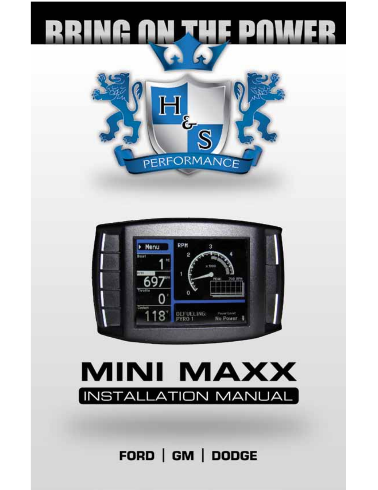
BILL OF MATERIALS
The list below includes by name the major parts included in your Mini Maxx package.
** Optional
BILL OF MATERIALS
1. Mini Maxx
• Micro SD Card
(in Mini Maxx)
2. Mini Maxx Power Cable
3. PCH Board**
• Screws (2)**
• Zip Ties (4)**
• Velcro Strip**
• Fuse Adapter**
4. Pyrometer Probe**
5. OBDII Adapter
6. Windshield Mount
7. Mini USB Cable
8. HDMI Cable
9. USB Adapter
1.
5. 6.
7.
9.
8.
**4.
**3.
2.
Page 6
6 Mini Maxx Installation Manual • www.hsperformance.com
PARTS DESCRIPTION
This section describes each of the parts in the Bill of Materials, the descriptions provide a physical set of
attributes and a purpose for each part. The parts descriptions also list everything that is included in each
assembly.
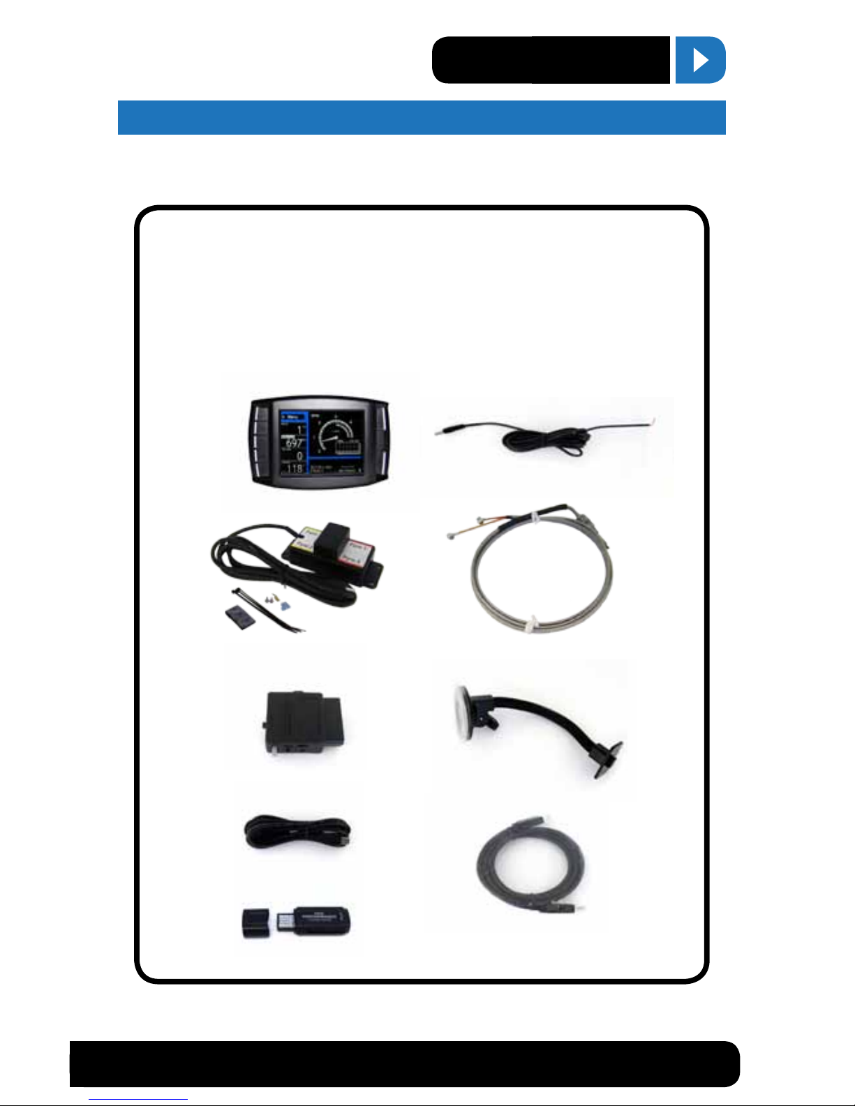
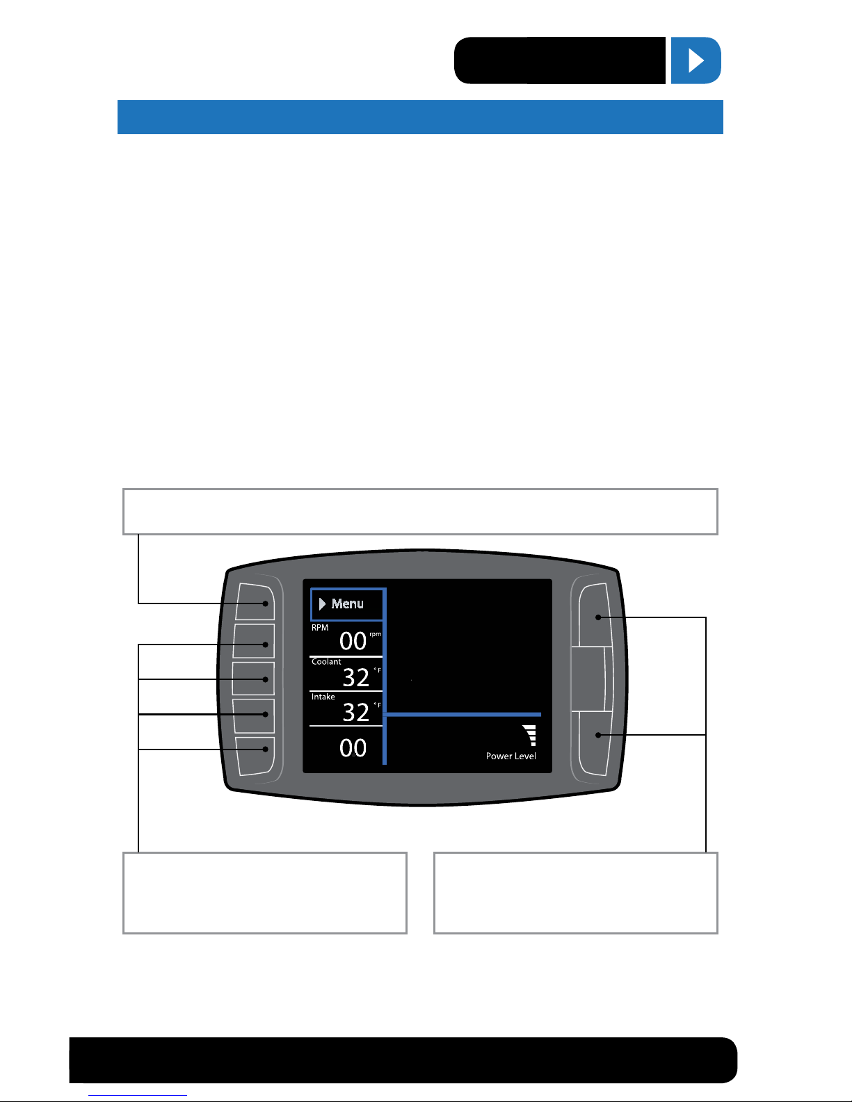
The Mini Maxx Head Unit
The main component is the Mini Maxx Head Unit. The Head
Unit is the interface in which you control vehicle performance parameters. It is also the brains that will save vehicle
activity and defuel a vehicle. Notice that the head unit has:
seven total buttons, ve on the left side and two on the right,
a large color screen, and an electronic plug for docking on
the back. Note that this is the last piece that you will install.
Note: Mini Maxx includes a micro SD card inserted
in the side of the Head Unit.
Power Cable
The Power cable connects the OBD ll Adaptor Plug to the vehicle fuse box to supply power to the Mini Maxx. It is optional
to use as there are two ways to power up your Mini Maxx
1. (Recommended) Use this power cable and wire it to the
designated location specied later in this manual.
2. The OBD II port provides constant 12V+ power, so your
Mini Maxx can power o of the OBD II port alone. But in
this situation the Mini Maxx will not turn on and o with
the ignition. There is a switch on the OBDII adapter plug
in order to turn the Mini Maxx on and o.
OBDII Adapter Plug
The OBDII Adapter is a communication hub for the Mini Maxx.
The OBD ll Adaptor plugs directly into the vehicle OBD ll port. Notice the OBD ll Adaptor has many ports to
support various other functions of the Mini Maxx.
PARTS DESCRIPTION
Page 7
1-888-628-1730 • Mini Maxx Installation Manual 7
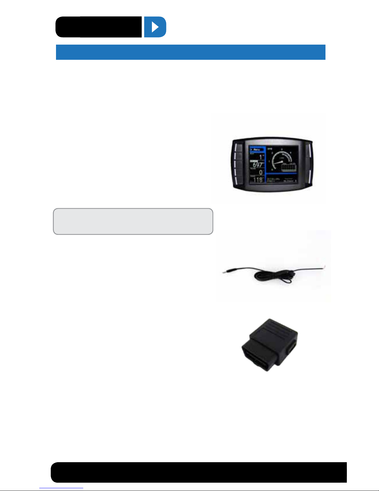
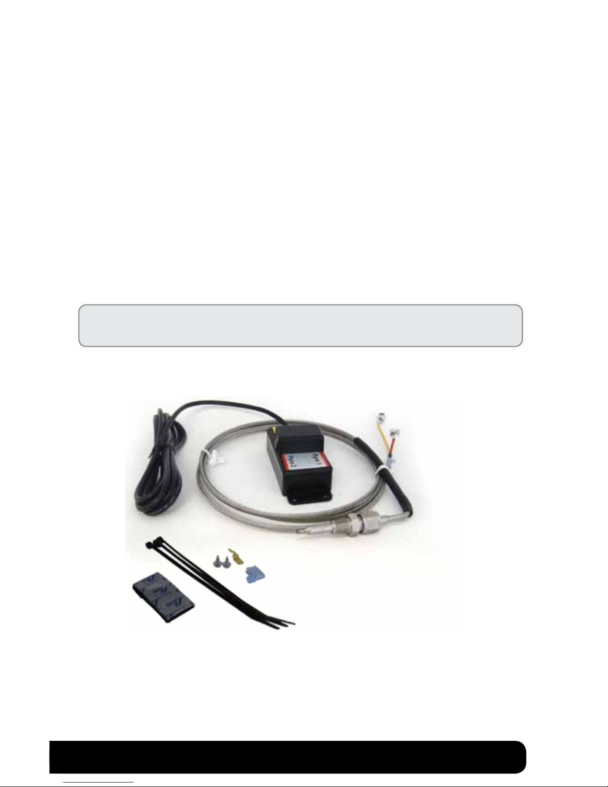
Pyrometer Connection Head (PCH) Board Assembly*
The PCH Board or Pyrometer Connection Head serves as a dock to connect the pyrometers into the Mini
Maxx system. The PCH Board includes the ability to connect two pyrometers. Attached to the PCH Board
housing is a cable with four pin plug which connects to the OBDII Adapter Plug. The list below includes all
separate parts that make up the entire PCH Board Assembly.
• PCH Board
• Velcro
• (2) Self-tapping Sheet Metal Screws
• Pyrometer Cable
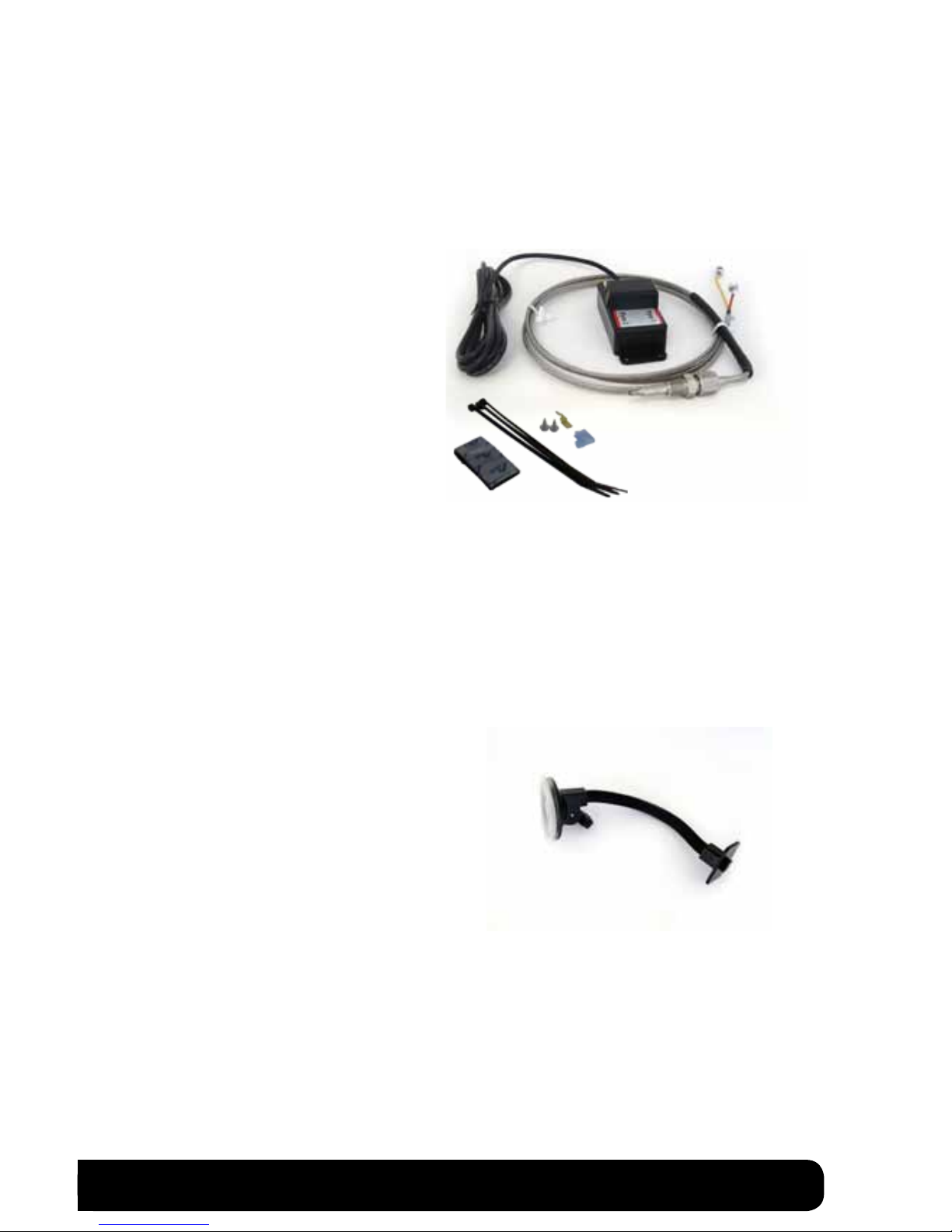
Universal Windshield Mount
This universal windshield mount is used to install the Mini Maxx rmly onto the windshield, it is a suction
cup mount that will work on any vehicle windshield. Check our web site for other mounting options, the Mini
Maxx is adaptable to a range of other mounting styles.
H&S Also oers custom vehicle specic solutions.
See www.hsperformance.com for details.
* Optional
Page 8
8 Mini Maxx Installation Manual • www.hsperformance.com
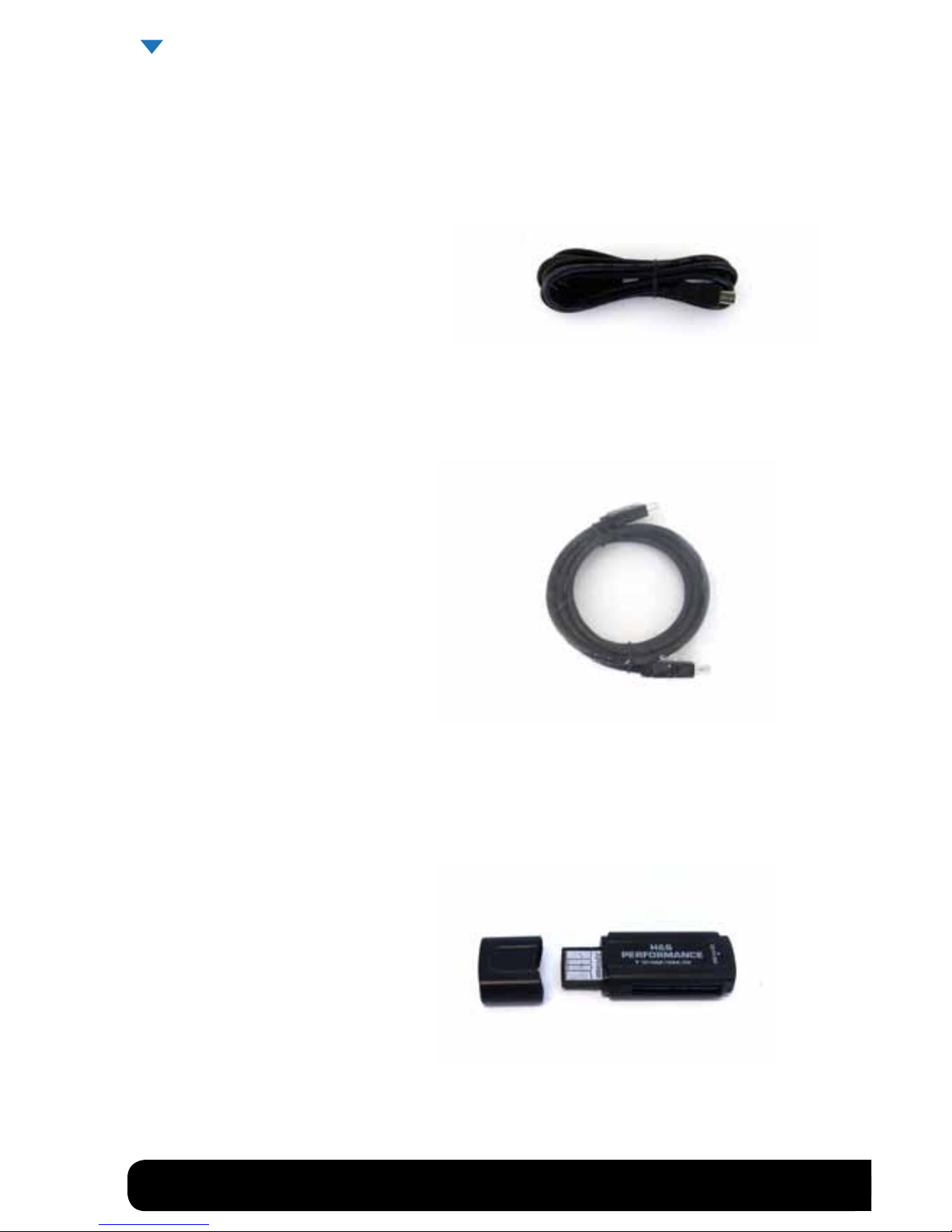
Mini USB Cable
Use this cable to connect your Mini Maxx to your personal computer to install software updates. Visit
www.hsperformance.com in the downloads section for product updates. Please nd your product application and follow the posted instructions there to update your Mini Maxx.
HDMI Cable
The HDMI Cable connects the Mini Maxx to the OBD ll Adapter Plug and acts as the main line of communication for the Mini Maxx.
USB to Micro SD Adapter
The USB to Micro SD Adapter is what you will use to update your Mini Maxx. You will take the Micro
SD card out of the Mini Maxx and insert it into the adapter, then insert the adapter into your personal
computer.
PARTS DESCRIPTION CONTINUED
Page 9
1-888-628-1730 • Mini Maxx Installation Manual 9
Mini Maxx & Windshield Mount
OBDII Adapter Plug
OBDII Port
Power Cable
(Optional)
Fuse Box
Fire wall grommet
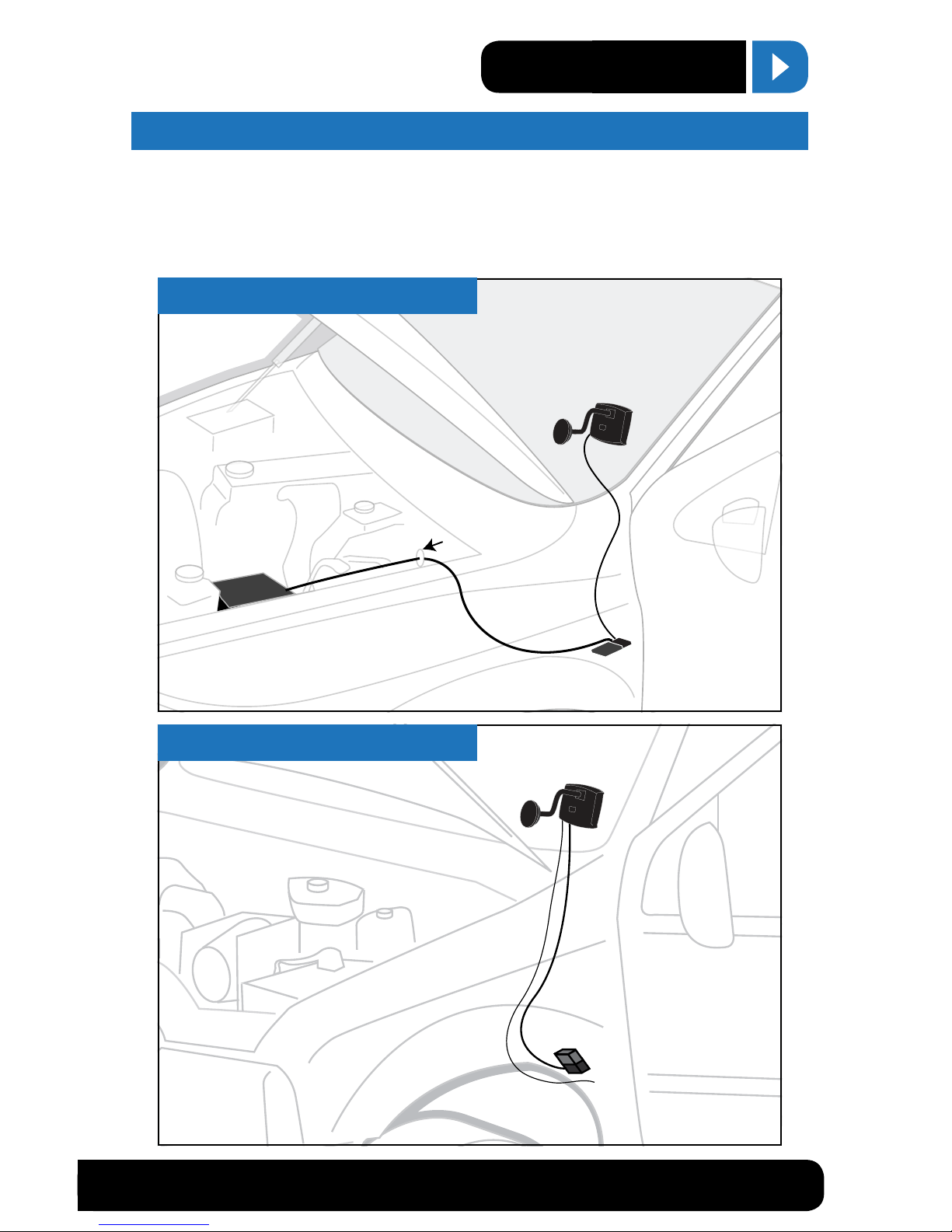
MOST APPLICATIONS
INSTALLATION OVERVIEW
The installation overview illustrates a totally installed and functional Mini Maxx system. This overview is
meant to help reference the general location of installed parts and pieces of the Mini Maxx. Notice that there
are dierent overview diagrams. Use the correct diagram for your truck. For more complete wiring diagrams
and instructions, please see vehicle specic features starting on page 30.
OBDII Port
OBDII Adapter Plug
Power Wire
(Optional. To purple
ignition
wire under dash)
MINI MAXX &
Windshield mount
HDMI Cable
FORD POWER STROKE ‘08’10
MINI MAXX INSTALLATION
Page 10
10 Mini Maxx Installation Manual • www.hsperformance.com
MINI MAXX INSTALLATION INSTRUCTIONS
SECTION 1: MOUNTING THE MINI MAXX
In this section you will decide where to mount the Mini Maxx Cradle, so you are essentially choosing the location for the Mini Maxx inside the vehicle cab. First, decide which mounting style you will choose for the Mini
Maxx; we oer two dierent styles of mounting:
1. Windshield mounting
2. Custom Pod mounting (Refer to the instructions included with your custom pod)
Visit hsperformance.com for custom options
INSTALLATION CONTINUED
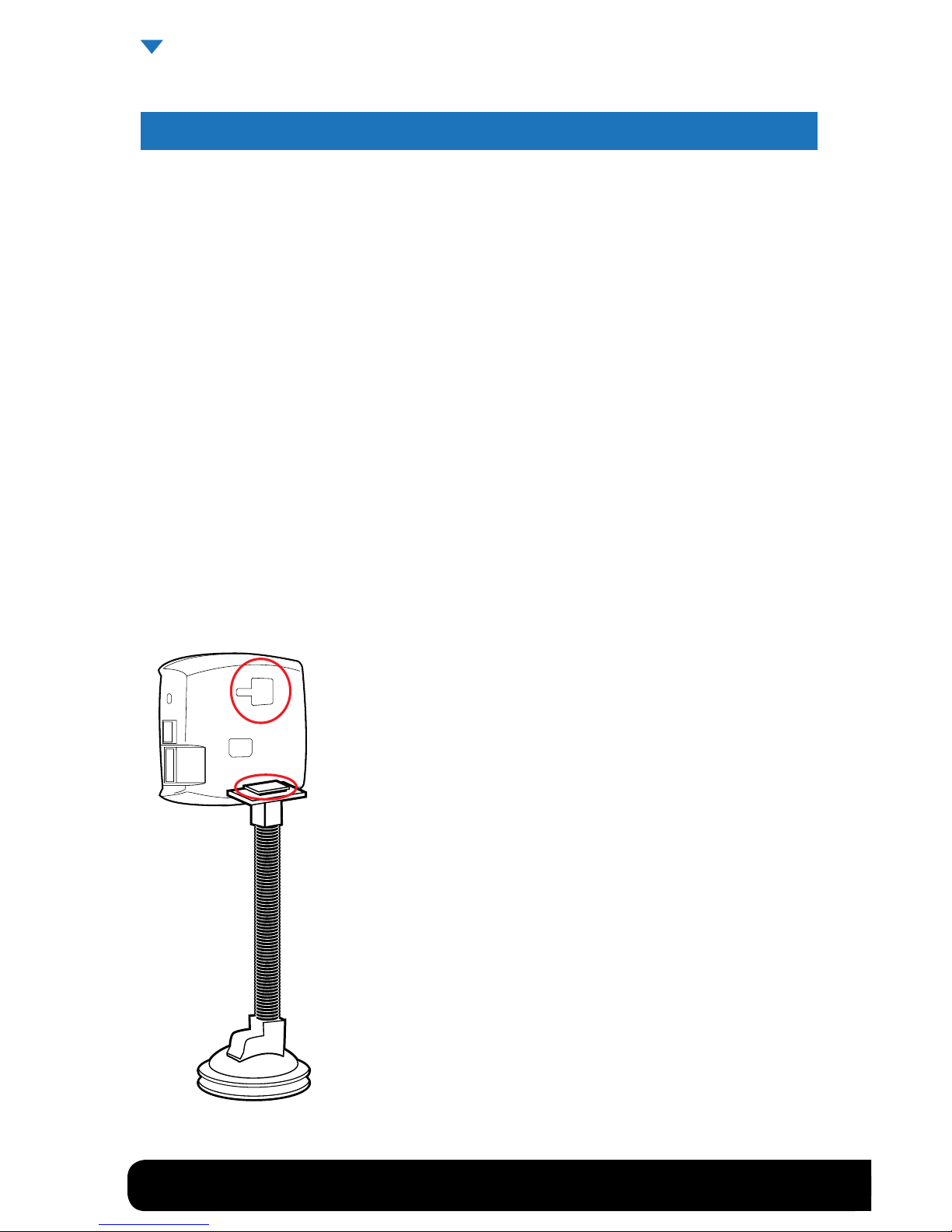
WINDSHIELD MOUNTING
1. Locate the T-shaped mount socket on the back side of the Mini Maxx.
2. Notice that the top of the universal mount will t into T-shaped socket and slide forward to
secure the Mini Maxx to the mount.
3. With the Mini Maxx connected to the mount use the windshield mount to secure the Mini Maxx
to the wind- shield. Be sure that the position of the Mini Maxx does not obstruct the view of
the road or distract the driver from their primary responsibility, which is driving responsible.
Page 11
1-888-628-1730 • Mini Maxx Installation Manual 11
SECTION 2: INSTALLING THE OPTIONAL PYROMETER AND THE PYROMETER CONNECTION
HEAD PCH
* The Pyrometer and PCH are optional and some vehicles will not require them. Your
vehicle may have a factory solution for reading Exhaust Gas Temperatures.
In this section you will drill and tap the Pyrometer Probe in the exhaust, either pre-turbo or postturbo as a means to collect exhaust gas temperatures (EGT). Exhaust gas temperatures indicate
how hot the motor is getting and can be used to set safety defueling parameters.
POSTTURBO VS. PRETURBO
You must decide between mounting the Pyro Probe either post-turbo or pre-turbo. The dierence in
location determines what temperatures will read on your Mini Maxx. Pre-turbo mounting is generally recommended because it provides more accurate EGT readings.
The Mini Maxx is capable of running two pyrometers simultaneously. Please purchase an extra probe
if you wish to read pre AND post turbo pyrometers.
Page 12
12 Mini Maxx Installation Manual • www.hsperformance.com
INSTALLATION CONTINUED
PRETURBO MOUNT
1. Drill a 5/16” hole into the exhaust manifold where all the exhaust runners of the manifold come together, just before the turbo exhaust inlet. Then tap the hole with a 1/8” NPT tap and mount the Pyrometer
Probe in the hole. Use a 9/16” wrench to tighten the probe holder or tube tting to the down tube. Then
tighten the Pyro Probe Cap to the holder using a 9/16” wrench.
2. Run the Pyro Cable up to engine bay; let the end of the cable sit while installing the PCH Board.
For pictures and vehicle specic information, see the Vehicle Specic Features/Info Section starting on Page 30
WARNING: If any debris such as drill bits and metal shavings drop inside the manifold, we advise
that the manifold be removed from the vehicle so that the debris can be removed before starting the
vehicle again.
TOOL TIP, PRETURBO MOUNT
When drilling into the exhaust manifold, metal spews, shavings, and broken drill bits can fall inside. This
can be hazardous to your turbo when the engine starts. Try doing four things to avoid this possible problem. One, use a high quality twist bit and a slow speed drill, about 500-800 rpm. Two, start with a small
pilot bit about 1/8”, then use the full 5/16” bit after the smaller one has punched through. Three, grease your
drill bit in addition to the normal lubricant, this will catch ying spews as they are cut. Four, just prior to
punching through into the inside of the manifold, start the engine and build up exhaust pressure on the
inside of the manifold (blows spews outside the manifold instead of letting them fall inside).
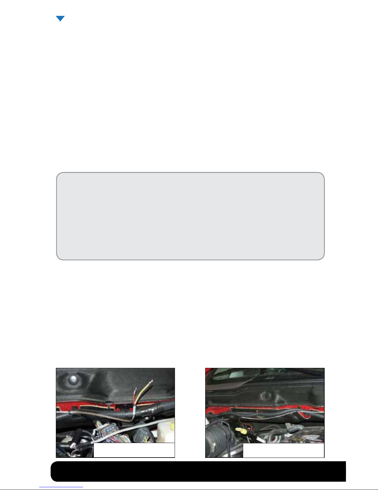
POSTTURBO MOUNT
1. Find a location on the exhaust pipe that is 3-6” downstream from the turbo charger output. Then drill a
5
/16” hole and run a 1/8” NPT tap into the hole. Mount the Pyrometer Probe in the threaded hole using a
9
/16” wrench to tighten the probe holder or tube tting to the down tube. Then tighten the Pyro Probe
Cap to the holder using a 9/16” wrench.
2. Run the Pyro Cable along the brim of the engine bay, and then let the end sit when installing the PCH
Board.
For pictures and vehicle specic information, see the Vehicle Specic Features/Info Section starting on Page 30
Securing Pyro
Pyro line secured
Page 13
1-888-628-1730 • Mini Maxx Installation Manual 13
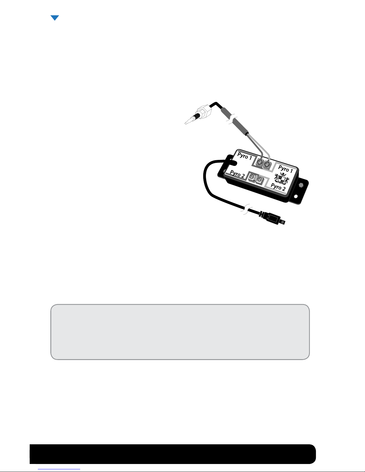
INSTALLING THE PCH BOARD
The pyrometer that was installed will now have to be connected to the PCH Board, but rst the PCH
Board needs to be mounted in a secure location that both of the pyrometer ends can reach.
1. Gather all of the parts of the PCH Board assembly:
•PyrometerConnectionHeadwithPCHCable
•Self-tappingSheetMetalScrews
•Velcro
•Jumper
•ZipTies
2. The PCH Board needs to be mounted in a location
that is secure (away from extreme heat and moving parts), and in a location in which the end of
the Pyrometer Cable can easily reach.
3. Use the sheet metal screws or Velcro, or both to
securely attach the PCH Board to a safe location
within the engine bay.
4. To connect the end of the Pyrometer Cable to the PCH Board, rst remove the screw and nut on
the end of the pyrometer leads, then remove the screws from the Pyro 1 heads on the PCH Board.
Use those screws to secure the Pyrometer Cable leads to the PCH Pyro 1 heads, see the PCH Assembly Diagram (pg. 19) for a visual reference when connecting the pyrometer leads to the PCH
Board.
Notice: Do not remove the jumper from the Pyrometer 2 location unless you are
installing a second pyrometer.
If connecting two pyrometers keep track of which location, Pyro 1 or 2, each
pyrometer was attached to on the PCH Board
5. Once the PCH Board is secure and the pyrometer is connected to the PCH Board, use zip ties to secure
the pyrometer cables away from extreme heat and moving parts.
6. Run the end of the PCH Cable through the re wall. It will need to be connected to the OBDII Adapter
Plug. Use zip ties to secure all remaining cable left inside the engine bay.
INSTALLATION CONTINUED
Page 14
14 Mini Maxx Installation Manual • www.hsperformance.com
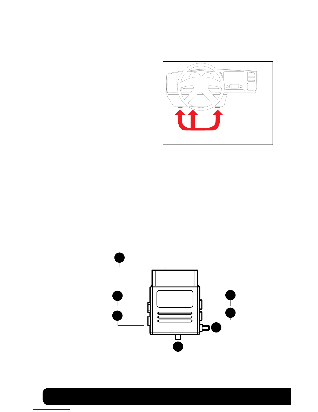
SECTION 3: OBDII ADAPTER PLUG
This step involves locating the vehicle’s OBD ll port and
then simply plugging the OBD ll Adapter Plug into the
OBD ll port.
1. As the illustration below shows, OBD ll ports
are always located somewhere under the drivers side dash. The OBD ll port is a male receiver
that will have the same shape as the end of the
OBD ll Adaptor plug.
2. Once the OBD ll port is located, then simply
plug the OBD ll Adaptor plug into the OBD ll
port.
OBDII ADAPTER PLUG DIAGRAM
1. OBD ll Male end: this is the part of the adapter plug that plugs into the vehicle OBD ll port.
2. Main harness port:
the main harness will plug into the Mini Maxx and into this port during installation.
3. Power wire port: the power wire will run from this port to the vehicle fuse box during installation.
Plug into the Mini Maxx and into this port during installation.
4. Power supply switch: use this switch to change power from running o of the Power Wire to OBD ll
power as a power supply for the Mini Maxx.
5. Four pin usb: This port is used if an H&S pyrometer kit is purchased for the Mini Maxx.
6. Five pin usb
7. Adapter plug fuse
Possible OBDII Port Locations
(location may vary)
1
5
6
7
2
3
4
Note: On some vehicles it is recommended to move the OBDII port to a safer location. Because the Mini Maxx will
remain plugged in, the adapter can be kicked/bumped and broken. Please move your OBDII connection to a safer
location if you feel it is in a position that may allow it to get damaged.
Page 15

1-888-628-1730 • Mini Maxx Installation Manual 15
SECTION 4: INSTALLING THE POWER WIRE *OPTIONAL
*The OBD II port provides constant 12V+ power, so your Mini Maxx can power o of the OBD II port alone.
But in this situation the Mini Maxx will not turn on and o with the ignition. There is a switch on the OBDII
adapter plug in order to turn the Mini Maxx on and o.
In this section you will run the Power Wire coming from the Mini Maxx Cradle to the vehicle fuse box and
connect it to the fuse locations specied below. The fuse location for the Power Wire is dierent on each
vehicle application.
CONNECTING THE POWER WIRE:
1. Route wire to location shown in pictures found in the Vehicle Specic Section on page 30
2. Remove the fuse, indicated in the pictures, and insert the fuse jack. Make sure that the fuse jack is placed
on the dead side of the fuse to ensure that the Mini Maxx is protected by the fuse. Use a volt meter to verify
the dead side of the fuse. With the fuse pulled and the truck powered on but not started, the volt meter
should read 0 volts on the fuse jack to ground. Problems that can occur if the incorrect fuse is used for
this connection: the power may stay on continuously even with the key o; or, the Mini Maxx can receive
power at the incorrect time of the power-on/starting cycle of the vehicle.
3. Run the power wire through the re wall before preparing the Power Wire. Prepare the Power Wire by
stripping the end of the wire about ¼”. Connect the blue 90° connector to the end of the Power Wire using
crimping pliers.
4. Connect the Power Wire to the fuse jack, place the fuse back into the slot, and close the fuse box.
Page 16
16 Mini Maxx Installation Manual • www.hsperformance.com
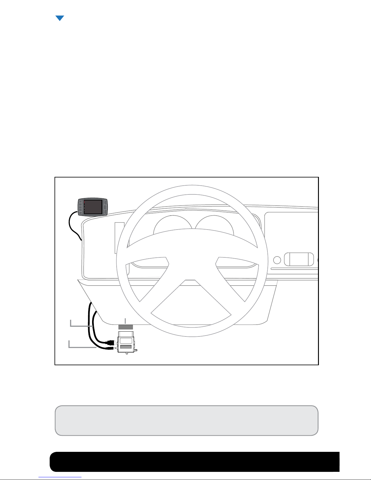
SECTION 5: RUN MINI MAXX HDMI CABLE
In this section you will connect the Mini Maxx HDMI cable to the OBD ll Adaptor plug and then run the other
end of the HDMI cable up the side of the vehicle dash and connect it to the back of the Mini Maxx.
1. Plug one end of the HDMI cable into the Main Harness port on the OBD ll adapter plug.
2. Run the other end of the HDMI cable up through the vehicle dash on the drivers side so that the end of
the cable emerges from the dash near the vehicle A-pillar. It may be necessary to temporarily remove
the vehicle weather stripping and dash panel to achieve an installation where the HDMI cable cannot
be seen.
3. Plug the HDMI cable into the back side of the Mini Maxx, make sure that there is enough slack in the
cable to accommodate mounting the Mini Maxx to the windshield.
Almost Done!
You need to install the download now. Read the next section for Install Download procedure.
INSTALLATION CONTINUED
OBDII Plug
Mini Maxx
Power Cable
HDMI Cable
Page 17
1-888-628-1730 • Mini Maxx Installation Manual 17
MINI MAXX OPERATING INSTRUCTIONS
These operating instructions are split into sections:
•SECTION 1: Button Navigation
•SECTION 2: Install Download
•SECTION 3: Exploring the Main Screen
•SECTION 4: Exploring the Menu System
•SECTION 5: Vehicle Setup
•SECTION 6: Other Mini Maxx Features
•SECTION 7: Vehicle Specic Features
•SECTION 8: Unplugging the Head Unit
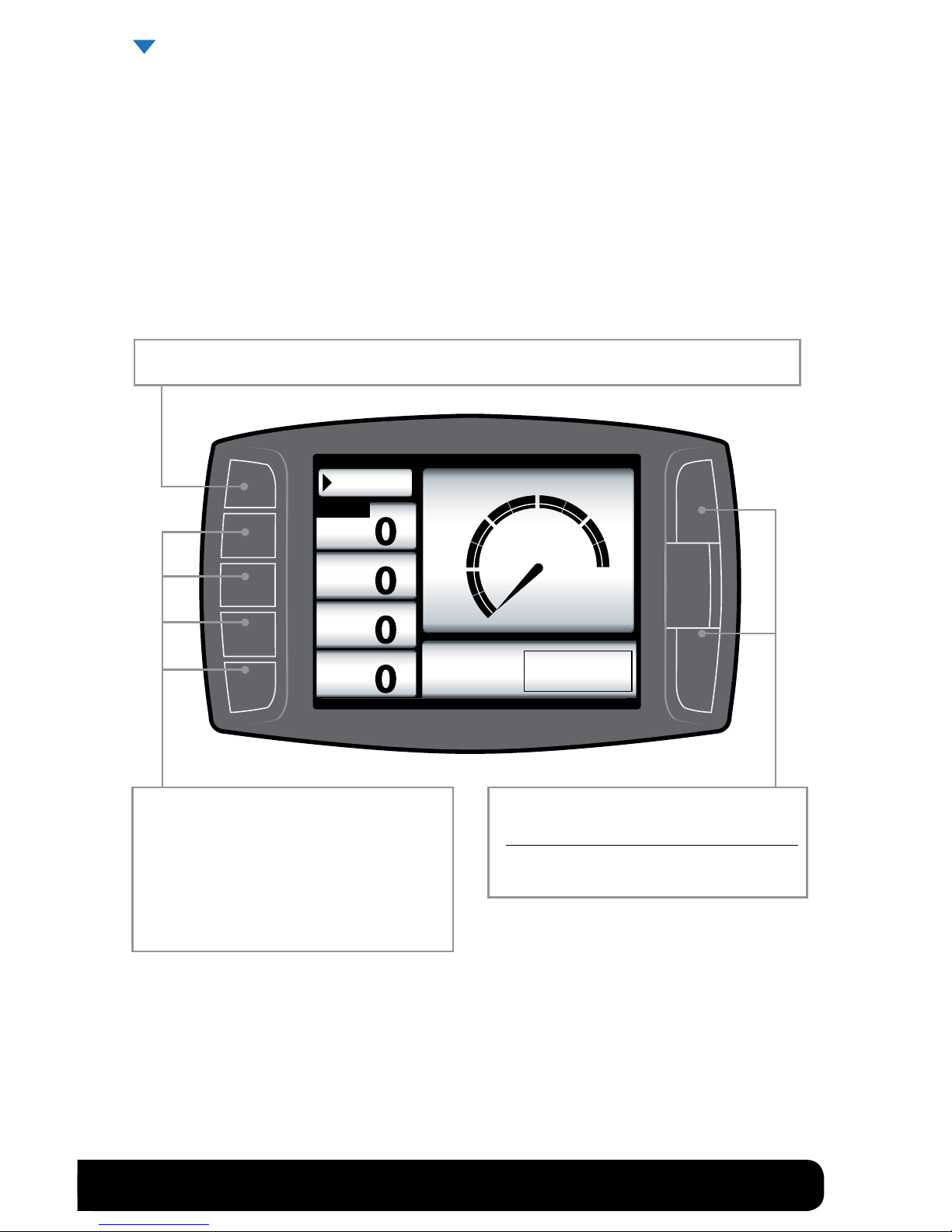
SECTION 1: BUTTON NAVIGATION
Mini Maxx OPERATION
Press the top left button to enter the Main Menu, also use this button to exit menus.
Press any of the four buttons on the left to
select items on the screen that are adjacent to
the button position.
In general these buttons work as up and down
buttons, they may also be used to select items
on the screen adjacent to these buttons.
Speed
MPH
Page 18

18 Mini Maxx Installation Manual • www.hsperformance.com
SECTION 2: INSTALL DOWNLOAD
The Install Download option is used to install tuning onto a vehicle, or return a vehicle to stock.
1. Press Menu: To get into the Mini Maxx main menu.
2. Select Install Download: You may have to “Arrow Down” or “Arrow Up” to nd this option.
3. Install a download onto a stock vehicle: If the vehicle is stock and you enter the install download
menu, simply follow the screen prompts to install a download on the vehicle. This is the point in which
you may come across the DPF selection menu, tire size calibration menu, and the vehicle speed limiter
menu.
Change Download Settings: If the vehicle already has a download on it from the Mini Maxx that is
currently installed on that vehicle. This option is used to install updated or custom tuning. Updated and
Custom tuning can be download for the H&S Performance website.
Return a vehicle to stock: To completely return a vehicle to its factory stock conditions you need to
select this option. This is highly recommended when taking the vehicle in for any kind of service.
This Mini Maxx screen shot shows what you will see if a download has already been entered into a vehicle.
Before installing the download:
•MakesurethattheMiniMaxxisproperlypluggedin.
•Makesurethattheharnessisproperlyinstalled.
•Thevehiclebatteryisfullycharged.
•Thevehicleiswarmeduptooperatingtemperature.
THE MICRO SD CARD MUST BE INSERTED IN THE SIDE OF THE MINI
MAXX TO DOWNLOAD TO A VEHICLE.
Go Back
DOWNLOAD INSTALLED
Return to Stock
Change Settings
Download Already Installed
Page 19
1-888-628-1730 • Mini Maxx Installation Manual 19
SECTION 3: EXPLORING THE MAIN SCREEN
The Main Screen is where you view all of the vehicle activity. In this section you will learn how to navigate
the Main Screen and learn about all of the dierent parts of the Main Screen.
MAIN SCREEN NAVIGATION
Below are descriptions of how all of the Mini Maxx buttons work and what they do while in the Main
Screen. The buttons perform dierent functions while in a menu or submenu.
Speed
MPH
RPM
RPM
Coolant
ºF
Throttle
X
Menu
MPH
0
30
60 120
90
Power Level Setting
not available until
download is installed.
Press any of the four buttons on the left that
coincide with the four vehicle parameters to
display that particular vehicle parameter on the
large gauge in the upper right side of the screen.
Hold a button down to view the dierent graph
types for the large gauge.
Power Level Up
Power Level Down
Use the power level buttons to control power
levels on-the-y only while in the main screen
Press the top left button to enter the Main Menu, also use this button to exit menus.
Mini Maxx OPERATION CONTINUED
Page 20

20 Mini Maxx Installation Manual • www.hsperformance.com
MAIN SCREEN PARTS DESCRIPTION
This section will describe all of the dierent parts of the Main Screen.
Speed
MPH
RPM
RPM
Coolant
ºF
Throttle
X
Menu
MPH
0
30
60 120
90
Power Level Setting
not available until
download is installed.
Large Gauge
Vehicle parameters: To change which vehicle
parameter is displayed in the large gauge area
simply press one of the four buttons next the
preferred vehicle parameter.
By pressing and holding the button next to your
displayed gauge, you can change the display
style in the large gauge area.
Menu button: press to enter the main menu.
Power level text: Displays which power level is
active, whether it be: Stock, Mild, Wild, or Hot.
Note: This will not be active if the Download has
not been installed.
The black bar: The black bar highlights the title of one of the four displayed vehicle parameters to indicate
that vehicle parameter is also being displayed on the large gauge.
Page 21

1-888-628-1730 • Mini Maxx Installation Manual 21
Go Back
MAIN MENU
to Main Screen
Install Download
Gauge Set Up
Set User Options
Set Defuel Levels
Adjust Tire Size
Diagnostics
Show Settings
Update Firmware
Navigation through the main menu: Use the
large Up Down Buttons to page up and
page down through all the Main Menu options.
These buttons are used
to enter into the sub
menus from the main
menu and may also be
used to select additional
items when in the sub
menus.
This button is used to enter into the Main Menu
from the main screen. While in any of the menus
this button works as a back button.
Mini Maxx OPERATION CONTINUED
SECTION 4: EXPLORING THE MENU SYSTEM
The diagram below shows all of the Main Menu items and explains the Main Menu navigation.
Page 22

22 Mini Maxx Installation Manual • www.hsperformance.com
DEFUELING PARAMETERS
Set up defueling parameters based on a number of dierent vehicle parameters. In this menu you
can also turn vehicle parameters o. The defueling parameters available are vehicle specic, so not
all defueling parameters are available for every make and model.
Here is a list of all of the defueling capabilities
for the Mini Maxx. All defueling options can be
activated at the same time, all can be turned o,
or a mix of on and o. Each defueling option is
adjusted individually to be on or o and set to a
particular defueling temperature.
Engine Coolant Temp Level
Boost Level
Go Back
DEFUEL MENU
Transmission Temperature
Oil Temperature
Pyro 1 Temperature Level
Pyro 2 Temperature Level
to Main Menu
Setting: 600˚F
Setting: 1250˚F
Setting: 210˚F
Setting: 260˚F
Setting: 210˚F
Setting: 23PSI
Use the Up Down Buttons to scroll up and
down through the dierent sub menu items.
Press to enter set up menu for defuel items.
Default Defueling Settings
Pyro 1 Temperature Level 1450˚F
Pyro 2 Temperature Level OFF
Engine Coolant Temp Hot 210°F
Engine Coolant Temp Cold
(cold start protection)
OFF
Boost Level OFF
Transmission Temp Level OFF
Oil Temperature OFF
Current setting are displayed in Defuel Menu
SECTION 5: VEHICLE SETUP
This section describes various non-vehicle specic features of the Mini Maxx
INSTRUCTIONS CONTINUED
Page 23

1-888-628-1730 • Mini Maxx Installation Manual 23
SET DEFUEL LEVELS
When entering a setup menu for any of the defuel options the menu will have a list of defuel levels
to select from based on that specic defuel parameter. The selected value is displayed on the left, to
select a defuel level you need only highlight the amount and then exit the setup menu. To turn any
particular defuel parameter o press the bottom left button.
Go Back
PYRO1
to Defuel Menu Set Deful Level
The selected defuel value
for PYRO 1 is displayed
in the box below:
Selected
OFF
DEFUEL OFF
DEFUEL ON
Go Back
PYRO1
to Defuel Menu Set Deful Level
up
down
Defueling Levels
1250
1300
1350
1400
1450
1500
1550
1600
The selected Defuel value
for PYRO 1 is displayed
in the box below:
Selected
1400º F
DEFUEL ON
DEFUEL OFF
Use the large Up Down Buttons to scroll up
and down through the dierent sub menu items.
Use this button to turn the defueling on.
Use this button to turn the defueling off.
Page 24

24 Mini Maxx Installation Manual • www.hsperformance.com
Set Gauge 2
Set Gauge 3
Set Gauge 4
Go Back
GAUGE SETUP
Set Gauge 1
Speed
RPM
Throttle
Coolant
Gauge 1
Use the Up and Down Arrows
to Change the Gauge Function
Pyro 2
Speed
Boost
to Main Menu
To highlight a dierent gauge location press the
selection button that coincides with that gauge
location. So to select gauge location 1, press the
second button down on the left hand side of the
Mini Maxx. To select the 4th gauge location press
the bottom button or the 5th button down on
the left side.
Use the large Up Down Buttons to highlight
a particular vehicle parameter for any of the
gauge locations.
Notice that upon entering the gauge setup menu that, Set Gauge 1, is highlighted in black. When a gauge
location is selected it is highlighted in black on the left and it also appears above the vehicle parameter
selection box.
SECTION 6: OTHER MINI MAXX FEATURES
This section describes all the customizing features of the Mini Maxx.
GAUGE SETUP
Enter to change the vehicle parameters displayed on the four gauge locations in the Main Screen. This is
also where you can see all of the most up-to-date vehicle parameters available to your vehicle make and
model after running an internet upgrade.
Selecting a vehicle parameter to display in a particular location is done by highlighting the gauge location and
then highlighting the desired vehicle parameter.
Once the correct vehicle parameter for a gauge location has been highlighted, you do not need to press another
button to select that vehicle parameter. Simply highlighting the vehicle parameter makes it active in that location.
Page 25

1-888-628-1730 • Mini Maxx Installation Manual 25
ADJUST BACKLIGHT
Highlight screen and use the up and down buttons to adjust the lighting to your preference.
Go Back
BACKLIGHTING
to User Opts
0 50 100
Brightness 100%
Screen Backlight
Select 0 to 100% using and
to set desired light level
Screen
Use this button select the ‘Screen’ option.
Use these
buttons to
adjust the
backlight
brightness
level.
CHANGE BACKGROUND COLOR
Use the up and down buttons to select a background color. The Mini Maxx background will
preview each color background as you scroll up and down through the color options. When
the preferred color is highlighted, exit the color menu to select the color.
Go Back
COLOR SETUP
to User Opts
Background
Black
Background
Use the up and down arrows
to change the gauge function
HSBlue
Bluelight
Use the large Up Down Buttons to scroll up and
down through the color options.
Page 26

26 Mini Maxx Installation Manual • www.hsperformance.com
PERFORMANCE TESTING
This sub menu allows you to run 1/4 mile and 0-60 MPH performance testing on your vehicle.
You must accept the on screen disclaimer before entering the Performance Testing menu.
• 1/4 MILE PERFORMANCE TEST
When selecting Start Test make sure that you are completely stopped. The testing
will begin when vehicle reads speed. The testing will automatically stop when you
have reached 1/4 mile. Test results and fastest times will be stored and viewable at
any time.
• 060 MPH PERFORMANCE TEST
When selecting Start Test make sure that you are completely stopped. The testing
will begin when vehicle reads speed. The testing will automatically stop when you
have reached 60 MPH. Test results will appear on screen.
0-60 MPH Performance Test
Congure Test Settings
Go Back
PERF TEST
1/4 Mile Performance Test
to Main Menu
NOTE: If running aftermarket tires or gearing, your speedometer must be calibrated correctly for performance test-
ing to yeild accurate results.
Page 27

1-888-628-1730 • Mini Maxx Installation Manual 27
DIAGNOSTICS
This function allows you to check vehicle diagnostics codes. Some models you will have an option
to check Engine or Transmission diagnostics. Please select the desired module. Upon entering this
menu, the Mini Maxx will automatically begin to check the vehicle for DTCs and it will then display
those DTCs on the Mini Maxx screen. Once it displays the DTCs value and description on the screen
it will allow you to erase the DTCs from the vehicle.
If no DTCs are displayed you can simply press the Go Back button to return to the main menu.
For a complete list of DTC descriptions, please visit the Tech section of our website
www.hsperformance.com
THE MICRO SD CARD MUST BE INSERTED IN THE SIDE OF THE MINI MAXX TO READ AND ERASE DTCS
DTC
Diagnostic Trouble Codes
Establishing communication
with the vehicle
Go Back
DTC
to Main Menu
Diagnostic Trouble Codes
There are no DTCs Detected
Page 28

28 Mini Maxx Installation Manual • www.hsperformance.com
RESET TO DEFAULT SETTING
To reset the Mini Maxx to H&S Performance factory settings press the up button to select yes, to
keep current settings back out of this menu by pressing the go back button or by pressing the
down button to select no.
Go Back
GO TO DEFAULT
to user opts
Selecting YES will reset user
preferences to factory set values.
Are you sure you want to do this at
this time? ( for YES)
yes
no
Page 29

1-888-628-1730 • Mini Maxx Installation Manual 29
SHOW SETTINGS
The Show Settings Menu will allow you to see vehicle information and also defuel settings. See the diagram
below to see everything that is listed in this menu. On Cummins and Powerstroke trucks, the Part# and
Transmission# will be needed for updating the Mini Maxx.
T.V. #
This number is the Tuning Version. It will change as H&S updates the tuner software. To see the latest tuner version on your Mini Maxx go to “Show Settings” and scroll down.
MICRO SD CARD
The Micro SD card should only be taken out of the Mini Maxx to perform internet upgrades. It is the primary
means of performing internet upgrades for the Mini Maxx.
In case a Micro SD Card is lost or broken, a new Micro SD Card can be purchased from H&S Performance.
WEB UPDATES
Remove the Micro SD from your Mini Maxx. Connect your Micro SD to your personal computer with the included
Micro SD to USB adapter to install software updates. Visit www.hsperformance.com in the downloads section for
product updates. Please nd your product application and follow the posted instructions there to update your
Mini Maxx.
Go Back
SETTINGS
to Main Menu
Vehicle Info:
Vehicle: ‘08 Ford Power Stroke
Vin#: 123456789101112131415
Part#: 55350430
Download: Installed
DPF Status: Removed
Trans Tuning: Locked
Application:
’07.5-’09 Dodge 6.7L Cummins
System Info:
Version: MEM–C216 HW–1.3b
SW–1.00.2 TV–6.7.4
M175 W/TURBO
Page 30

30 Mini Maxx Installation Manual • www.hsperformance.com
Power Levels
Power Levels can be adjusted on-the-y at the touch of a button after Installing the Download to the vehicle. The current
Power Level will be saved even if the Mini Maxx is unplugged.
NOTE: The Power Level ratings listed may not be exact for your particular
vehicle. The listed ratings apply to the out-of-the-box tuning that H&S tuning
devices are shipped with. Any custom downloads may result in dierent ratings and can be found at www.hsperformance.com/mini-maxx-downloads.
Low Boost Fueling
This option allows for adjustment of the amount of fuel injected under low boost conditions.
There are 5 dierent settings for Low Boost Fueling:
0 - Lowest Fueling (Default)
1 - Low Fueling
2 - Medium Fueling
3 - Moderate Fueling
4 - High Fueling
NOTE: The low boost fueling adjustment will aect ALL power levels. This option can only be adjusted during the
Install Download process.
Injection Timing
This option allows for the adjustment of the maximum allowed injection timing. There are 5
dierent settings for the Injection Timing:
0 - 18 degrees
1 - 24 degrees
2 - 26 degrees (Default)
3 - 28 degrees
4 - 32 degrees
NOTE: The injection timing adjustment will aect ALL power levels. This option can only be adjusted during the
Install Download process.
2003 2007 5.9L DODGE CUMMINS
Power LeveLs
No Power ............. 0 HP
Mild
................... 60 HP
Wild
................. 120 HP
Hot
.................. 200 HP
SECTION 7: VEHICLE SPECIFIC FEATURES/INFO
Page 31

1-888-628-1730 • Mini Maxx Installation Manual 31
Speed Limiter
This option allows for the adjustment of the factory speed limiter. Most 5.9L Cummins trucks have a
106 MPH speed limiter from the factory. The limiter can be adjusted from 50 MPH to 200 MPH. This
option can only be adjusted during the Install Download process.
Rev Limiter
This option allows for the adjustment of the factory rev limiter. Most 5.9L Cummins trucks have a
3500 RPM rev limiter from the factory. The limiter can be adjusted from 3000 RPM to 5000 RPM. This
option can only be adjusted during the Install Download process.
Torque Management (Automatic Transmission Only)
This option allows for the disabling of the vehicles torque management for those equipped with
automatic transmissions. This is recommend for those running standalone aftermarket TCM/transmission packages but will also slightly improve throttle response on a stock truck.
NOTE: By turning the torque management OFF, the PRNDL display will be lost as well as the reverse lights.
Tire Size Calibration
This option allows for the re-calibration of the factory speedometer to adjust for non-stock sized
tires. For the most accurate speedometer reading when using non-stock sized tires, it is best to
measure the diameter of the tire using a tape measure rather than going by the printed tire size. In
additon, using a GPS is a great way to dial in your factory speedometer. Entering a larger tire size
will cause the factory speedometer to read higher while entering a smaller tire size will cause the
factory speedometer to read lower. The tire size can be adjusted from 24” to 42”. This option only
takes a few seconds to change and can be adjusted at any time from the Tire Size Calibration menu.
Keyed Ignition Source Location
Although it is possible to manually power up the Mini Maxx without using a keyed ignition source,
it can sometimes create communication issues between the Mini Maxx and the vehicles ECM. To
eliminate these problems, we highly recommend tapping into a 12V keyed ignition source to supply
power to the Mini Maxx only when the key is in the ON position and the vehicles ECM is online.
Below you will nd a commonly used 12V keyed ignition source for your vehicle:
2006-2007 5.9L - FUSE NUMBER 30
Always tap into the cold side of the fuse. On the
2006 - 2007 5.9L Cummins, the cold side is towards
the drivers side of the vehicle.
2003 - 2005 5.9L - FUSE NUMBER 50
Always tap into the cold side of the fuse. On the
Page 32

32 Mini Maxx Installation Manual • www.hsperformance.com
2003 - 2005 5.9L Cummins, the cold side is towards
the front of the vehicle.
NOTE: If your fuse box or wiring looks dierent than those pictured
or if you are not getting 12V ignition power from the pictured source,
you may need to nd another 12V keyed ignition source using a test
light or multimeter. If possible, nd one that stays hot during engine
cranking.
Pyrometer (EGT) Location
If you are installing an optional H&S pyrometer kit on your 5.9L Cummins, you have the
option of installing it pre-turbo or post-turbo (or both if you purchased an additional
thermocouple).
For the most accurate EGT readings, we recommend installing the pyrometer pre-turbo
where all runners collect on the exhaust manifold as seen below:
NOTE: Some exhaust manifolds have a divider down the center of
the collector so it’s generally not a good idea to drill right in the center,
shift to either side 1/4” and drill there.
For those wanting to install the pyrometer post-turbo, we usually recommend doing so in
the cast elbow connected to the turbo as seen below:
NOTE: Post-turbo EGT readings can be up to 400 degrees cooler
than pre-turbo EGT readings. Keep that in mind when monitoring
your EGTs with a post-turbo pyrometer.
**Pre-turbo mount is recommended.
Dodge Pre-Turbo Mount
Dodge Post-Turbo Mount
2003 - 2007 5.9L Dodge Cummins Specic Features Continued >>
Page 33

1-888-628-1730 • Mini Maxx Installation Manual 33
Overdrive Transmission Software
Did you know that your H&S tuning device also has the capability of tuning your transmission? If
your 5.9L Cummins is equipped with the 48RFE automatic transmission, you may want to check
out our Overdrive Transmission Software. Custom tailored to mate with H&S engine tuning,
the 5.9L Overdrive software includes modied torque converter lock/unlock strategies that will
command the TC to lock in 3rd gear under wide open throttle and hold it locked through 4th gear.
Light throttle torque converter strategies have also been changed to lock-up sooner, keeping more
power directed to the road instead of wasted in heat and friction. Shift points are modied to
take advantage of the available horsepower and torque output. On a 2006 Cummins with a stock
48RFE,wehaveseen0.2to0.3secondquicker1/4miletimesJUSTfromtheadditionoftheH&S
Overdrive tuning! An additional unlock fee may apply, see www.hsperformance.com for details.
2007.5 2009 6.7L DODGE CUMMINS
Power Levels
Power Levels can be adjusted on-the-y at the touch of a button
after Installing the Download to the vehicle. The unit cannot be
unplugged otherwise the Power Level will default to NO POWER.
NOTE: The Power Level ratings listed may not be exact for your particular
vehicle. The listed ratings apply to the out-of-the-box tuning that H&S tuning
devices are shipped with. Any custom downloads may result in dierent ratings and can be found at www.hsperformance.com/mini-maxx-downloads.
DPF Selection
The DPF or Diesel Particulate Filter is part of the factory exhaust
system on the 6.7L Cummins. H&S oers tuning that allows the
DPF to be left in place, or removed completely.
If you are planning on leaving the exhaust system stock with
the DPF in place, you will select PRESENT.
If you have already removed the DPF or if you plan on removing
the DPF immediately after installing your H&S tuning device,
you will select REMOVED. If you select REMOVED, you must Accept our DPF Disclaimer in order to continue with the Install Download process.
DPF / Exhaust Sensors
When running DPF PRESENT tuning, it is required that all sensors located in the exhaust
system stay in place and plugged in, otherwise you may experience a Check Engine Light
Power LeveLs
DPF Present
No Power ............. 0 HP
Mild
................... 40 HP
Wild
................... 80 HP
Hot
................... 120 HP
Power LeveLs
DPF removeD
No Power ............. 0 HP
Mild
................... 60 HP
Wild
................. 120 HP
Hot
................... 175 HP
Page 34

34 Mini Maxx Installation Manual • www.hsperformance.com
(CEL) and even a loss of power (limp mode).
When running DPF REMOVED tuning, it is recommended that all sensors located in the
factory exhaust system be unplugged from the electrical harnesses. These sensors can also
be removed completely with the factory exhaust if desired. On the 2007.5 - 2009 6.7L Cummins, there are usually 3 EGT Sensors, 2 O2 Sensors, and 1 Pressure Sensor.
EGR Unplug / Delete
If you are installing H&S DPF REMOVED tuning, you must unplug the EGR system on your 2007.5 - 2009
6.7L Cummins if not installing an EGR delete. Failing to do so may result in erratic engine operation and
loss of power. Please follow these instructions carefully to unplug and disable the EGR system:
1. Locate the EGR Throttle Control Valve Assembly (Fig.1). Assembly is located between the intercooler and intake manifold on the drivers side of the engine compartment.
2. Unplug the EGR Throttle Control Valve wiring harness. The harness is LIGHT GRAY in color and
is located on the back side of the Throttle Control Valve Assembly. It is not directly visible when
looking at the assembly from above. On some vehicles, it may be easier to see and unplug
the harness from underneath the vehicle. Note: There is a red locking tab that must be moved
sideways on the harness in order for it to be unplugged.
3. Locate the EGR solenoid on top of the intake manifold (Fig.2). It is directly visible when looking
at the intake manifold and faces towards the front of the vehicle.
4. Unplug the EGR solenoid wiring harness. The connector is BROWN in color.
Speed Limiter
This option allows for the adjustment of the factory speed limiter. Most 6.7L Cummins trucks have a
106 MPH speed limiter from the factory. The limiter can be adjusted from 55 MPH to 200 MPH. This
option can only be adjusted during the Install Download process.
Tire Size Calibration
This option allows for the re-calibration of the factory speedometer to adjust for non-stock sized tires.
For the most accurate speedometer reading when using non-stock sized tires, it is best to measure
1
2
2007.5 - 2009 6.7L Dodge Cummins Specic Features Continued >>
Page 35

1-888-628-1730 • Mini Maxx Installation Manual 35
the diameter of the tire using a tape measure rather than going by the printed tire size. In additon,
using a GPS is a great way to dial in your factory speedometer. Entering a larger tire size will cause
the factory speedometer to read higher while entering a smaller tire size will cause the factory
speedometer to read lower. The tire size can be adjusted from 25.5” to 45”. This option only takes a
few seconds to change and can be adjusted at any time from the Tire Pressure Calibration menu.
Special Functions / Features
Your H&S tuning device has the capability of Enabling / Disabling factory vehicle features. These
features can be found in the Special Functions Menu. Below is a short description of each feature:
TPMS: Enable / Disable the Tire Pressure Monitoring System.
Optical Chirp on Lock: Enable / Disable the parking lights ashing when locking the vehicle.
Horn Chirp on Lock: Enable / Disable the horn chirp when locking the vehicle.
Set Headlamp Delay: Enable / Disable the headlamp delay.
Accessory Delay: Enable / Disable the shut-o delay of your radio and accessory system after the key has
been turned o.
Fog Lights W/High: Enable / Disable the fog lights staying on when high beams are being used.
Daytime Lights: Enable / Disable the daytime running lights.
Seat Belt Minder: Enable / Disable the chime for the drivers seat belt system. This feature will not dis-
able the seat belt light.
Auto Door Lock: Enable / Disable the automatic door locking when the vehicle reaches certain speeds.
Unlock Driver Door:
Enable / Disable unlocking only the driver door when pushing the unlock button the key-
fob. When enabled, the unlock button on the key fob will need to be pressed twice in order to unlock all doors.
Idle Up (Auto Only): Enable / Disable the use of the cruise control buttons to control idle RPM. Follow
your vehicle owners manual to use this feature
NOTE: If any special feature is already listed as Enabled but is not functioning correctly, you may need to disable the
feature, cycle the key, and re-enable the feature to make it function properly. If it still does not work, your vehicle may
not be equipped with the hardware required for the special feature. The previous selection will NOT be saved. If the
Special Functions/Features Menu is exited and returned into, it will not display your previous selection. This is normal
and the Enable/Disable function is still working properly.
Keyed Ignition Source Location
Although it is possible to manually power up the Mini Maxx without using a keyed ignition source,
it can sometimes create communication issues between the Mini Maxx and the vehicles ECM. To
eliminate these problems, we highly recommend tapping into a 12V keyed ignition source to supply power to the Mini Maxx only when the key is in the ON position and the vehicles ECM is online.
Below you will nd a commonly used 12V keyed ignition source for your vehicle:
Page 36

36 Mini Maxx Installation Manual • www.hsperformance.com
FUSE NUMBER 30
Always tap into the cold side of the fuse. On the
2007.5 - 2009 6.7L Cummins, the cold side is towards
the drivers side of the vehicle.
NOTE: If your fuse box or wiring looks dierent than those pictured
or if you are not getting 12V ignition power from the pictured source,
you may need to nd another 12V keyed ignition source using a test
light or multimeter. If possible, nd one that stays hot during engine cranking.
Pyrometer (EGT) Location:
If you are installing an optional H&S pyrometer kit on your 6.7L Cummins, you have the option of installing it pre-turbo or post-turbo (or both if you purchased an additional thermocouple).
For the most accurate EGT readings, we recommend installing the pyrometer pre-turbo
where all runners collect on the exhaust manifold as seen below:
NOTE: Some exhaust manifolds have a divider down the center of the
collector so it’s generally not a good idea to drill right in the center, shift
to either side 1/4” and drill there.
For those wanting to install the pyrometer post-turbo, we usually recommend doing so in
the cast elbow connected to the turbo as seen below:
NOTE: Post-turbo EGT readings can be up to 400 degrees cooler than
pre-turbo EGT readings. Keep that in mind when monitoring your EGTs
with a post-turbo pyrometer.
**Pre-turbo mount is recommended.
Overdrive Transmission Software
Did you know that your H&S tuning device also has the capability of tuning your transmission? If
your 6.7L Cummins is equipped with the 68RFE automatic transmission, you may want to check
out our Overdrive Transmission Software. Custom tailored to mate with H&S engine tuning, the
6.7L Overdrive software includes boosted line pressures, modied full and part throttle torque
Dodge Pre-Turbo Mount
Dodge Post-Turbo Mount
2007.5 - 2009 6.7L Dodge Cummins Specic Features Continued >>
Page 37

1-888-628-1730 • Mini Maxx Installation Manual 37
converter lock/unlock strategies, adjusted full and part throttle shift points, adjusted full and part
throttle shift rmness, modied torque management tables, and much more! All changes are designed to keep more power directed to the road instead of wasted in heat and friction. On our test
trucks,wehaveseen0.2to0.3secondquicker1/4miletimesJUSTfromtheadditionoftheH&S
Overdrive tuning! An additional unlock fee may apply, see www.hsperformance.com for details.
2010 2012 6.7L DODGE CUMMINS
Power Levels
Power Levels can be adjusted onthe-y at the touch of a button
after Installing the Download to
the vehicle. The unit cannot be
unplugged otherwise the Power
Level will default to NO POWER.
NOTE: The Power Level ratings listed
may not be exact for your particular
vehicle. The listed ratings apply to the
out-of-the-box tuning that H&S tuning
devices are shipped with. Any custom
downloads may result in dierent
ratings and can be found at www.hsperformance.com/mini-maxx-downloads.
DPF Selection
The DPF or Diesel Particulate Filter
is part of the factory exhaust
system on the 6.7L Cummins.
H&S oers tuning that allows the
DPF to be left in place, or removed completely.
If you are planning on leaving the exhaust system stock with the DPF in place, you will select
PRESENT.
If you have already removed the DPF or if you plan on removing the DPF immediately after
installing your H&S tuning device, you will select REMOVED. If you select REMOVED, you must
Accept our DPF Disclaimer in order to continue with the Install Download process.
DPF / Exhaust Sensors
When running DPF PRESENT tuning, it is required that all sensors located in the exhaust
2011 Cab & Chassis
Power LeveLs
DPF Present
No Power ............. 0 HP
Mild
................... 20 HP
Wild
................... 40 HP
Hot
..................... 60 HP
2010-2012 PiCkuP
Power LeveLs
DPF Present
No Power ............. 0 HP
Mild
................... 40 HP
Wild
................... 80 HP
Hot
................... 120 HP
2011 Cab & Chassis
Power LeveLs
DPF removeD
No Power ............. 0 HP
Mild
................... 25 HP
Wild
................... 50 HP
Hot
..................... 75 HP
2010-2012 PiCkuP
Power LeveLs
DPF removeD
No Power ............. 0 HP
Mild
................... 60 HP
Wild
................. 120 HP
Hot
................... 175 HP
Page 38

38 Mini Maxx Installation Manual • www.hsperformance.com
system stay in place and plugged in, otherwise you may experience a Check Engine Light
(CEL) and even a loss of power (limp mode).
When running DPF REMOVED tuning, it is recommended that all sensors located in the
factory exhaust system be unplugged from the electrical harnesses. These sensors can also
be removed completely with the factory exhaust if desired. On the 2010 - 2012 Pickup, there
are usually 3 EGT Sensors, 2 O2 Sensors, and 1 Pressure Sensor.
2011 Cab & Chassis UREA System
On the 2011 Cab & Chassis, there is usually an additional NOX sensor as well as a UREA
system that needs to be unplugged when running DPF REMOVED tuning. The UREA system
must at least be unplugged but can be completely removed from the vehicle if desired.
Failure to unplug the UREA system may result in a check engine light and/or dash messages.
Follow these instructions to unplug the UREA system:
1. Locate the wiring harness with the YELLOW sliding lock-tab on the Urea pump assembly.
The pump assembly is located near the bottom of the ller neck support.
2. Slide the yellow lock-tab DOWN to dis-engage the lock and unplug the harness.
For complete UREA System Removal instructions, visit
www.hsperformance.com/tech/CCUrea.pdf.
2010 - 2012 6.7L Dodge Cummins Specic Features Continued >>
Page 39

1-888-628-1730 • Mini Maxx Installation Manual 39
EGR Unplug / Delete
Unlike the previous years, it is no longer mandatory to unplug the EGR system when installing H&S DPF REMOVED tuning. You may still unplug the EGR system if desired, or the EGR
system may be left plugged in without any ill eects. The entire EGR system can also be
completely removed with an H&S EGR Delete Kit when running H&S DPF REMOVED tuning.
Speed Limiter
This option allows for removal of the factory speed limiter. Most 6.7L Cummins trucks have a
106 MPH speed limiter from the factory. This option can only be changed during the Install
Download process.
Torque Management (Manual Transmission Only)
This option allows for the disabling of the vehicles torque management for those equipped
with manual transmissions. This option increases pedal sensitivity and throttle response
when REMOVED.
Tire Size Calibration
This option allows for the re-calibration of the factory speedometer to adjust for non-stock sized
tires. For the most accurate speedometer reading when using non-stock sized tires, it is best to
measure the diameter of the tire using a tape measure rather than going by the printed tire size.
In addition, using a GPS is a great way to dial in your factory speedometer. Entering a larger tire
size will cause the factory speedometer to read higher while entering a smaller tire size will cause
the factory speedometer to read lower. The tire size can be adjusted from 25.5” to 45”. This option
can only be seen/changed after the Download is Installed to the vehicle. This option only takes a
few seconds to change and can be adjusted at any time from the Tire Size Calibration menu.
Special Functions / Features
Your H&S tuning device has the capability of Enabling / Disabling factory vehicle features.
These features can be found in the Special Functions Menu. These features can only be seen/
changed after the Download is Installed to the vehicle. Below is a short description of each
feature:
TPMS: Enable / Disable the Tire Pressure Monitoring System.
Optical Chirp on Lock: Enable / Disable the parking lights ashing when locking the vehicle.
Horn Chirp on Lock: Enable / Disable the horn chirp when locking the vehicle.
Set Headlamp Delay: Enable / Disable the headlamp delay.
Accessory Delay: Enable / Disable the shut-o delay of your radio and accessory system after the key has
been turned o.
Page 40

40 Mini Maxx Installation Manual • www.hsperformance.com
Fog Lights W/High: Enable / Disable the fog lights staying on when high beams are being used.
Daytime Lights: Enable / Disable the daytime running lights.
Seat Belt Minder: Enable / Disable the chime for the drivers seat belt system. This feature will not dis-
able the seat belt light.
NOTE: If any special feature is already listed as Enabled but is not functioning correctly, you may need to disable
the feature, cycle the key, and re-enable the feature to make it function properly. If it still does not work, your vehicle
may not be equipped with the hardware required for the special feature. The previous selection will NOT be saved.
If the Special Functions/Features Menu is exited and returned into, it will not display your previous selection. This is
normal and the Enable/Disable function is still working properly.
Stationary Idle Adjust:
The Stationary Idle Adjust Menu will allow you to adjust the idle speed of your vehicle while
in Park or Neutral using your H&S tuning device. Choose the desired idle speed and select
Set to set the idle speed to the chosen RPM. Idle speed can be adjusted from 700 RPM to
1500 RPM.
Keyed Ignition Source Location
Although it is possible to manually power up the Mini Maxx without using a keyed ignition
source, it can sometimes create communication issues between the Mini Maxx and the
vehicles ECM. To eliminate these problems, we highly recommend tapping into a 12V keyed
ignition source to supply power to the Mini Maxx only when the key is in the ON position
and the vehicles ECM is online. Below you will nd a commonly used 12V keyed ignition
source for your vehicle:
2010 6.7L Pickup and 2011 6.7L Cab & Chassis
FUSE NUMBER M45
Always tap into the cold side of the fuse. On the
2010 Pickup and 2011 Cab & Chassis, the cold side is
towards the front of the vehicle.
2011-2012 6.7L Pickup
FUSE NUMBER M33
Always tap into the cold side of the fuse. On the
2011 Pickup, the cold side is towards the front of the
vehicle.
2010 - 2012 6.7L Dodge Cummins Specic Features Continued >>
Page 41

1-888-628-1730 • Mini Maxx Installation Manual 41
NOTE: If your fuse box or wiring looks dierent than those pictured or if you are not getting 12V ignition power from
the pictured source, you may need to nd another 12V keyed ignition source using a test light or multimeter. If pos-
sible, nd one that stays hot during engine cranking.
Pyrometer (EGT) Location
If you are installing an optional H&S pyrometer kit on your 6.7L Cummins, you have the option of installing it pre-turbo or post-turbo (or both if you purchased an additional thermocouple).
For the most accurate EGT readings, we recommend installing the pyrometer pre-turbo
where all runners collect on the exhaust manifold as seen below:
NOTE: Some exhaust manifolds have a divider down the center of the
collector so it’s generally not a good idea to drill right in the center, shift
to either side 1/4” and drill there.
For those wanting to install the pyrometer post-turbo, we usually recommend doing so in the
cast elbow connected to the turbo as seen below:
NOTE: Post-turbo EGT readings can be up to 400 degrees cooler than
pre-turbo EGT readings. Keep that in mind when monitoring your EGTs
with a post-turbo pyrometer.
Overdrive Transmission Software
Did you know that your H&S tuning device also has the capability of tuning your transmission? If your 6.7L
Cummins is equipped with the 68RFE Automatic Transmission, you may want to check out our Overdrive
Transmission Software. Custom tailored to mate with H&S engine tuning, the 6.7L Overdrive software
includes boosted line pressures, modied full and part throttle torque converter lock/unlock strategies,
adjusted full and part throttle shift points, adjusted full and part throttle shift rmness, modied torque
management tables, and much more! All changes are designed to keep more power directed to the road
instead of wasted in heat and friction. On our test trucks, we have seen 0.2 to 0.3 second quicker 1/4 mile
timesJUSTfromtheadditionoftheH&SOverdrivetuning!Anadditionalunlockfeemayapply,seewww.
hsperformance.com for details.
Dodge Pre-Turbo Mount
Dodge Post-Turbo Mount
Page 42

42 Mini Maxx Installation Manual • www.hsperformance.com
2003 2007 6.0L FORD POWERSTROKE
Power Levels
Power Levels can be adjusted on-the-y at the touch of a button after Installing the Download to the vehicle. The current
Power Level will be saved even if the Mini Maxx is unplugged.
NOTE: The Power Level ratings listed may not be exact for your particular
vehicle. The listed ratings apply to the out-of-the-box tuning that H&S tuning
devices are shipped with. Any custom downloads may result in dierent rat-
ings and can be found at www.hsperformance.com/mini-maxx-downloads.
EGR Delete
With H&S tuning installed, the EGR system on the 6.0L Powerstroke can be completely
removed with an EGR Delete Kit while remaining code free.
Speed Limiter
This option allows for the removal of the factory speed limiter. Most 6.0L Powerstroke trucks
have a 95 MPH speed limiter from the factory. The limiter can be removed completely or left
stock (this may change so be sure to visit www.hsperformance.com for product updates). This option can
only be changed during the Install Download process.
Tire Size Calibration
(Not currently available for the 2003 - 2007 6.0L Powerstroke. This may change so be sure to visit www.
hsperformance.com for product updates) This option allows for the re-calibration of the factory
speedometer to adjust for non-stock sized tires. For the most accurate speedometer reading
when using non-stock sized tires, it is best to measure the diameter of the tire using a tape
measure rather than going by the printed tire size. In addition, using a GPS is a great way to
dial in your factory speedometer. Entering a larger tire size will cause the factory speedometer to read higher while entering a smaller tire size will cause the factory speedometer to
read lower. This option can only be adjusted during the Install Download process.
Power LeveLs
No Power ............. 0 HP
Mild
................... 40 HP
Wild
................... 80 HP
Hot
.................. 120 HP
Video In Motion
This feature will allow customers with a factory installed Chrysler 730N DVD/Navigation unit
to unlock all features that are normally blocked while driving. Full destination input into
the navigation system is now available, even while the vehicle is moving, as well as DVD
playback on the front screen. May require additional unlock fee. For more info see
www.hsperformance.com/store/dodge-video-in-motion-unlock-code.html
2010 - 2012 6.7L Dodge Cummins Specic Features Continued >>
Page 43

1-888-628-1730 • Mini Maxx Installation Manual 43
Keyed Ignition Source Location
Although it is possible to manually power up the Mini Maxx without using a keyed ignition source,
it can sometimes create communication issues between the Mini Maxx and the vehicles ECM. To
eliminate these problems, we highly recommend tapping into a 12V keyed ignition source to supply power to the Mini Maxx only when the key is in the ON position and the vehicles ECM is online.
Below you will nd a commonly used 12V keyed ignition source for your vehicle:
FUSE NUMBER 15
Always tap into the cold side of the fuse. On the
2003 - 2007 6.0L Powerstroke, the cold side is towards
the driver side of the vehicle.
NOTE: If your fuse box or wiring looks dierent than those pictured
or if you are not getting 12V ignition power from the pictured source,
you may need to nd another 12V keyed ignition source using a test
light or multimeter. If possible, nd one that stays hot during engine cranking.
Pyrometer (EGT) Location
If you are installing an optional H&S pyrometer kit on your 6.0L Powerstroke, you have
the option of installing it pre-turbo or post-turbo (or both if you purchased an additional
thermocouple).
For the most accurate EGT readings, we recommend installing the pyrometer pre-turbo in
the driver side exhaust manifold as seen below:
NOTE: The driver side exhaust manifold can be easily accessed from
underneath the vehicle. Be sure to drill straight into the exhaust
manifold otherwise the pyrometer probe may hit the manifold wall
during installation.
For those wanting to install the pyrometer post-turbo, we usually recommend doing so
somewhere in the downpipe.
NOTE: The downpipe is pretty thin in most places, so be extra careful when tapping and installing the probe tting.
Post-turbo EGT readings can be up to 400 degrees cooler than pre-turbo EGT readings. Keep that in mind when
monitoring your EGTs with a post-turbo pyrometer.
6.0L Pre-Turbo Mount
Page 44

44 Mini Maxx Installation Manual • www.hsperformance.com
2008 2010 6.4L FORD POWERSTROKE
Power Levels
Power Levels can be adjusted on-the-y at the touch of a button after Installing the Download to the vehicle. The current
Power Level will be saved even if the Mini Maxx is unplugged.
NOTE: The Power Level ratings listed may not be exact for your particular
vehicle. The listed ratings apply to the out-of-the-box tuning that H&S tuning
devices are shipped with. Any custom downloads may result in dierent rat-
ings and can be found at www.hsperformance.com/mini-maxx-downloads.
DPF Selection
The DPF or Diesel Particulate Filter is part of the factory exhaust system on the 6.4L Powerstroke. H&S oers tuning that
allows the DPF to be left in place, or removed completely.
If you are planning on leaving the exhaust system stock with
the DPF in place, you will select PRESENT.
If you have already removed the DPF or if you plan on removing the DPF immediately after installing your H&S tuning
device, you will select REMOVED. If you select REMOVED, you
must Accept our DPF Disclaimer in order to continue with the Install Download process.
DPF / Exhaust Sensors
When running DPF PRESENT tuning, it is required that all sensors located in the exhaust
system stay in place and plugged in, otherwise you may experience a Check Engine Light
(CEL) and even a loss of power (limp mode).
When running DPF REMOVED tuning, it is recommended that all sensors located in the factory exhaust system be unplugged from the electrical harnesses. These sensors can also be
removed completely with the factory exhaust if desired. On the 6.4L Powerstroke, there are
usually 2 EGT Sensors and 1 Pressure Sensor.
NOTE: The vehicle will not run with sensors removed unless DPF REMOVED tuning is installed.
EGR Unplug / Delete
When running H&S DPF REMOVED tuning, it is not required to unplug or block-o the EGR
system on your 6.4L Powerstroke to disable it. The EGR system is already disabled in the
tuning and will not function under any conditions. If desired, the entire EGR system can be
unplugged, blocked-o, or completely removed when running H&S DPF REMOVED tuning.
Power LeveLs
DPF Present
No Power ............. 0 HP
Mild
................... 40 HP
Wild
................... 80 HP
Hot
................... 120 HP
Power LeveLs
DPF removeD
No Power ............. 0 HP
Mild
................... 80 HP
Wild
................. 160 HP
Hot
................... 250 HP
Page 45

1-888-628-1730 • Mini Maxx Installation Manual 45
Low Boost Fueling Adjustment
This adjustment allows you to limit the amount of fuel delivered based upon turbo boost
levels. 0 will have the least smoke output, 5 will have the most. By skipping this feature, the
tuning will default to level 2.
Speed Limiter
This option allows for the adjustment of the factory speed limiter. Most 6.4L Powerstroke
trucks have a 95 MPH speed limiter from the factory. The limiter can be adjusted from 55
MPH to 200 MPH. This option can only be adjusted during the Install Download process.
Tire Size Calibration
This option allows for the re-calibration of the factory speedometer to adjust for non-stock
sized tires. For the most accurate speedometer reading when using non-stock sized tires, it
is best to measure the diameter of the tire using a tape measure rather than going by the
printed tire size. In additon, using a GPS is a great way to dial in your factory speedometer.
Entering a larger tire size will cause the factory speedometer to read higher while entering a
smaller tire size will cause the factory speedometer to read lower. The tire size can be adjusted from 25” to 45”. This option can only be adjusted during the Install Download process.
TPMS Adjustability / Disable
Many 2008 - 2010 6.4L Powerstrokes are equipped with a TPMS or Tire Pressure Monitoring
System from the factory. This system is designed to alert the driver of a problem with the
vehicles tire pressures but is often a nagging inconvenience for those individuals wanting to run lower pressures or get rid of the TPMS sensors altogether. H&S Performance
has a designed solution for those individuals. By using your H&S tuning device and a 6.4L
Powerstroke TPMS Adapter (Part #709913), you will have full control of the TPMS. Front and
rear tire pressures will be independently adjustable from 0 - 100 PSI as well as the option to
Disable the TPMS completely if removing the TPMS sensors from the vehicle. All changes to
the TPMS must be done with the 6.4L Powerstroke TPMS Adapter in place and the Adapter
must be removed after changes are made to resume normal tuner function.
Transmission Relearn
The 5R110 automatic transmission on the 2008 - 2010 6.4L Powerstroke has what is called
Adaptive Memory and is constantly learning and adapting to dierent horsepower levels,
temperatures, driving habits, etc. After completing the Install Download process on the 6.4L
Powerstroke, the Transmission Adaptive Memory is automatically reset. We highly recommend performing a Transmission Relearn procedure after installing H&S tuning to help the
transmission perform correctly with the added horsepower. The 5R110 automatic transmission will eventually learn over time on its own, but the relearn procedure gives a good
Page 46

46 Mini Maxx Installation Manual • www.hsperformance.com
baseline for the adaptive learning and helps to speed up the learning process. To perform
the relearn procedure, please follow these instructions:
When re-training the transmission, ALWAYS follow posted speed limits. Do NOT attempt runs in adverse weather conditions such as snow, ice, rain, wind, or any other
conditions that may aect your vehicles traction or impair your visibility!
1. After H&S tuning is installed, perform each of the following 0-80 MPH runs while in the
HOT power level. During this relearn process, you may experience hesitation during shifts,
hard shifts, or defuel patterns, all of which are normal:
• 0-80 MPH @ 25% throttle position, then slow down and come to a complete stop.
• 0-80 MPH @ 50% throttle position, then slow down and come to a complete stop.
• 0-80 MPH @ 100% throttle position, then slow down and come to a complete stop.
The Transmission Relearn procedure is complete.
NOTE: On any vehicle using 3” or larger lift blocks under the rear leaf pack, it is HIGHLY RECOMMENDED to install
traction bars. With any added horsepower, failure to do so may result in harsh shifting and may cause premature
transmission and/or driveline damage.
Keyed Ignition Source Location
Although it is possible to manually power up the Mini Maxx without using a keyed ignition
source, it can sometimes create communication issues between the Mini Maxx and the
vehicles ECM. To eliminate these problems, we highly recommend tapping into a 12V keyed
ignition source to supply power to the Mini Maxx only when the key is in the ON position
and the vehicles ECM is online. Below you will nd a commonly used 12V keyed ignition
source for your vehicle:
SOLID PURPLE WIRE
The SOLID PURPLE wire (capped from the factory) is found under the drivers side dash. This
SOLID PURPLE wire is bundled with multiple other capped wires near the OBD-II port.
NOTE: If your fuse box or wiring looks dierent than those pictured
or if you are not getting 12V ignition power from the pictured
source, you may need to nd another 12V keyed ignition source using a test light or multimeter. If possible, nd one that stays “hot”
during engine cranking.
2008 - 2010 6.4L Ford Powerstroke Specic Features Continued >>
Page 47

1-888-628-1730 • Mini Maxx Installation Manual 47
Pyrometer (EGT) Location
On the 6.4L Powerstroke, the Mini Maxx takes advantage of a factory EGT sensor located in
the passenger side up-pipe. This factory sensor gives very accurate pre-turbo EGT readings
so no aftermarket pyrometer is needed although you may purchase and install additional
pyrometers to monitor pre-turbo and post-turbo temperatures if desired.
20112012 6.7L FORD POWERSTROKE
Power Levels
Power Levels can be adjusted on-the-y at the touch of a
button after Installing the Download to the vehicle. The unit
cannot be unplugged otherwise the Power Level will default
to NO POWER.
NOTE: The Power Level ratings listed may not be exact for your particular
vehicle. The listed ratings apply to the out-of-the-box tuning that H&S tuning
devices are shipped with. Any custom downloads may result in dierent rat-
ings and can be found at www.hsperformance.com/mini-maxx-downloads.
DPF Selection
The DPF or Diesel Particulate Filter is part of the factory exhaust system on the 6.7L Powerstroke. H&S oers tuning that
allows the DPF to be left in place, or removed completely.
If you are planning on leaving the exhaust system stock with
the DPF in place, you will select PRESENT.
If you have already removed the DPF or if you plan on removing the DPF immediately after installing your H&S tuning
device, you will select REMOVED. If you select REMOVED, you
must Accept our DPF Disclaimer in order to continue with the Install Download process.
DPF / Exhaust Sensors
When running DPF PRESENT tuning, it is required that all sensors located in the exhaust
system stay in place and plugged in, otherwise you may experience a Check Engine Light
(CEL) and even a loss of power (limp mode).
When running DPF REMOVED tuning, it is recommended that all sensors located in the factory exhaust system be unplugged from the electrical harnesses. These sensors can also be
Power LeveLs
DPF Present
No Power ............. 0 HP
Mild
................... 40 HP
Wild
................... 80 HP
Hot
................... 120 HP
*An additional unlock fee may
apply for DPF Present tuning.
Power LeveLs
DPF removeD
No Power ............. 0 HP
Mild
................... 50 HP
Wild
................. 100 HP
Hot
................... 150 HP
*An additional unlock fee may
apply for DPF Removed tuning.
*All tuning for this model requires $100 Unlock fee (part #111005) to function.
Page 48

48 Mini Maxx Installation Manual • www.hsperformance.com
removed completely with the factory exhaust if desired. On the 6.7L Powerstroke, there are
usually 3 EGT Sensors, 1 NOX Sensor, 1 UREA Injector, and 1 Pressure Sensor.
NOTE: The vehicle will not run with sensors removed unless DPF REMOVED tuning is installed.
UREA / SCR System
On the 2011 - 2012 6.7L Powerstroke, there is a UREA system that can be unplugged or
removed completely when running DPF REMOVED tuning. The UREA system may also be left
plugged in with no ill eects.
EGR Unplug / Delete
If you are installing H&S DPF REMOVED tuning, you must unplug the EGR system on your
2011-2012 6.7L Powerstroke if not installing an EGR delete. Failing to do so may result in
damage to your EGR parts.
Please follow these instructions carefully to unplug and disable the EGR system:
1. Unplug Orange EGR harness found on top of the EGR cooler assembly. The yellow lock tab
must be slid out before the harness can be unplugged.
2. Unplug the EGR Buttery Valve located near the radiator fan shroud.
2011 - 2012 6.7L Ford Powerstroke Specic Features Continued >>
Page 49

1-888-628-1730 • Mini Maxx Installation Manual 49
Speed Limiter
This option allows for the adjustment of the factory speed limiter. Most 6.7L Powerstroke
trucks have a 98 MPH speed limiter from the factory. The limiter can be changed to 75 MPH
or removed completely (this may change so be sure to visit www.hsperformance.com for product updates).
This option can only be changed during the Install Download process.
Tire Size Calibration
This option allows for the re-calibration of the factory speedometer to adjust for non-stock
sized tires. For the most accurate speedometer reading when using non-stock sized tires, it
is best to measure the diameter of the tire using a tape measure rather than going by the
printed tire size. In additon, using a GPS is a great way to dial in your factory speedometer.
Entering a larger tire size will cause the factory speedometer to read higher while entering a smaller tire size will cause the factory speedometer to read lower. The tire size can be
adjusted from 31” to 34” (this may change so be sure to visit www.hsperformance.com for product updates).
This option only takes a few seconds to change and can be adjusted at any time from the
Tire Size Calibration menu.
TPMS Adjustability / Disable
Many 2011 - 2012 6.7L Powerstrokes are equipped with a TPMS or Tire Pressure Monitoring
System from the factory. This system is designed to alert the driver of a problem with the
vehicles tire pressures but is often a nagging inconvenience for those individuals wanting to
run lower pressures or get rid of the TPMS sensors altogether.
With your H&S tuning device, you have full control of the TPMS. Front and rear tire pressures
are independently adjustable from 0-120 PSI as well as the option to disable the TPMS completely if removing the TPMS sensors from the vehicle. This option only takes a few seconds
to change and can be adjusted at any time from the Tire Pressure Calibration menu.
NOTE: TPMS adjustments will not take full eect on a stationary vehicle. Once adjustments have been made, it can
take up to 5 miles of driving before changes take eect.
Transmission Tuning
Did you know that your H&S tuning device also has the capability of tuning your transmission? Our transmission tuning for the 6R140 automatic transmission is custom tailored to
mate with H&S engine tuning. Some features include: boosted line pressures, modied full
and part throttle lock/unlock strategies, adjusted full and part throttle shift points, adjusted
full and part throttle shift rmness, and modied torque management tables. All changes
Page 50

50 Mini Maxx Installation Manual • www.hsperformance.com
are designed to keep more power directed to the road instead of wasted in heat and friction.
Onourtesttrucks,wehaveseen0.2to0.3secondquicker1/4miletimesJUSTfromtheaddition of H&S transmission tuning! An additional unlock fee may apply, see
www.hsperformance.com for details.
Transmission Relearn
The 6R140 automatic transmission on the 2011 - 2012 6.7L Powerstroke has what is called
Adaptive Memory and is constantly learning and adapting to dierent horsepower levels,
temperatures, driving habits, etc. If you selected to tune the transmission during the Install
Download process, the Transmission Adaptive Memory is automatically reset when the
download completes. We highly recommend performing a Transmission Relearn procedure
after installing H&S transmission tuning to help the transmission perform correctly with the
added horsepower. The 6R140 automatic transmission will eventually learn over time on its
own, but the relearn procedure gives a good baseline for the adaptive learning and helps
to speed up the learning process. To perform the relearn procedure, please follow these
instructions:
When re-training the transmission, ALWAYS follow posted speed limits. Do NOT attempt runs in adverse weather conditions such as snow, ice, rain, wind, or any other
conditions that may aect your vehicles traction or impair your visibility!
3. After H&S tuning is installed, perform each of the following 0-80 MPH runs while in the
HOT power level. During this relearn process, you may experience hesitation during shifts,
hard shifts, or defuel patterns, all of which are normal:
• 0-80 MPH @ 25% throttle position, then slow down and come to a complete stop.
• 0-80 MPH @ 50% throttle position, then slow down and come to a complete stop.
• 0-80 MPH @ 100% throttle position, then slow down and come to a complete stop.
The Transmission Relearn procedure is complete.
NOTE: On any vehicle using 3” or larger lift blocks under the rear leaf pack, it is HIGHLY RECOMMENDED to install
traction bars when adding additional horsepower.
Keyed Ignition Source Location
Although it is possible to manually power up the Mini Maxx without using a keyed ignition
source, it can sometimes create communication issues between the Mini Maxx and the
vehicles ECM. To eliminate these problems, we highly recommend tapping into a 12V keyed
ignition source to supply power to the Mini Maxx only when the key is in the ON position
and the vehicles ECM is online. Below you will nd a commonly used 12V keyed ignition
source for your vehicle:
2011 - 2012 6.7L Ford Powerstroke Specic Features Continued >>
Page 51

1-888-628-1730 • Mini Maxx Installation Manual 51
FUSE NUMBER 52
Always tap into the cold side of the fuse. On the
2011 - 2012 6.7L Powerstroke, the cold side is towards
the passengers side of the vehicle.
NOTE: If your fuse box or wiring looks dierent than those pictured
or if you are not getting 12V ignition power from the pictured source,
you may need to nd another 12V keyed ignition source using a test
light or multimeter. If possible, nd one that stays hot during engine cranking.
Pyrometer (EGT) Location
Unlike the 6.4L Powerstroke, there is no factory EGT sensor to get a reading from on the
6.7L Powerstroke when running DPF REMOVED tuning. Also, due to the reverse head ow
design, there are few options for mounting an aftermarket pyrometer pre-turbo. H&S oers
a couple solutions for this problem:
1. H&S EGT KIT (Part #302202): For those not wanting to get rid of the entire EGR system
just yet, this is a cheap, easy way to get accurate EGT readings. This kit includes two blocko plates - one for the EGR exhaust inlet and one for the EGR exhaust manifold outlet. A
bung is pre-welded on the exhaust manifold block-o plate that allows you to install one
of the EGT sensors from the DPF system into the passenger side exhaust manifold. Full
color instructions are included with the kit, see www.hsperformance.com/store for more
information.
2. H&S EGR DELETE KIT (Part #302201): The H&S EGR Delete Kit for the 2011 - 2012 6.7L
Powerstroke comes with everything you need to remove the entire EGR system from the
vehicle and includes a pre-welded bung on the exhaust manifold block-o plate that
allows you to install one of the EGT sensors from the DPF system into the passenger side
exhaust manifold. Full color instructions are included with the kit, see
www.hsperformance.com/store for more information.
Page 52

52 Mini Maxx Installation Manual • www.hsperformance.com
Page 53

1-888-628-1730 • Mini Maxx Installation Manual 53
2007.52010 6.6L LMM DURAMAX
Power Levels
Power Levels can be adjusted on-the-y at the touch of a button after Installing the Download to the vehicle. The current
Power Level will be saved even if the Mini Maxx is unplugged.
NOTE: The Power Level ratings listed may not be exact for your particular
vehicle. The listed ratings apply to the out-of-the-box tuning that H&S tuning
devices are shipped with. Any custom downloads may result in dierent rat-
ings and can be found at www.hsperformance.com/mini-maxx-downloads.
DPF Selection
The DPF or Diesel Particulate Filter is part of the factory
exhaust system on the 6.6L LMM Duramax. H&S oers tuning
that allows the DPF to be left in place, or removed completely.
If you are planning on leaving the exhaust system stock with
the DPF in place, you will select PRESENT.
If you have already removed the DPF or if you plan on removing the DPF immediately after installing your H&S tuning
device, you will select REMOVED. If you select REMOVED. you
must Accept our DPF Disclaimer in order to continue with the Install Download process.
DPF / Exhaust Sensors
When running DPF PRESENT tuning, it is required that all sensors located in the exhaust
system stay in place and plugged in, otherwise you may experience a Check Engine Light
(CEL) and even a loss of power (limp mode).
When running DPF REMOVED tuning, it is recommended that all sensors located in the factory exhaust system be unplugged from the electrical harnesses. These sensors can also be
removed completely with the factory exhaust if desired. On the 6.6L LMM Duramax, there
are usually 2 EGT Sensors and 1 Pressure Sensor.
Power LeveLs
DPF Present
No Power ............. 0 HP
Mild
................... 40 HP
Wild
................... 80 HP
Hot
................... 120 HP
Power LeveLs
DPF removeD
No Power ............. 0 HP
Mild
................... 60 HP
Wild
................. 120 HP
Hot
................... 175 HP
Page 54

54 Mini Maxx Installation Manual • www.hsperformance.com
EGR Unplug / Delete
When running H&S DPF REMOVED tuning, it is not required to unplug or block-o the EGR
system on your 6.6L LMM Duramax to disable it. The EGR system is already disabled in the
tuning and will not function under any conditions. If desired, the entire EGR system can be
unplugged, blocked-o, or completely removed when running H&S DPF REMOVED tuning.
Speed Limiter
This option allows for the adjustment of the factory speed limiter. Most 6.6L LMM Duramax
trucks have a 98 MPH speed limiter from the factory. The limiter can be adjusted from 50
MPH to 95 MPH or removed completely. This option can only be adjusted during the Install
Download process.
Tire Size Calibration
This option allows for the re-calibration of the factory speedometer to adjust for non-stock
sized tires. For the most accurate speedometer reading when using non-stock sized tires, it
is best to measure the diameter of the tire using a tape measure rather than going by the
printed tire size. In additon, using a GPS is a great way to dial in your factory speedometer.
Entering a larger tire size will cause the factory speedometer to read higher while entering
a smaller tire size will cause the factory speedometer to read lower. The tire size can be adjusted from 25” to 60”. This option can only be adjusted during the Install Download process.
NOTE: On some vehicles, entering a tire size larger than 35” may cause the ABS light to illuminate.
Transmission Reset / Relearn
The automatic transmission on the 2007.5 - 2010 6.6L LMM Duramax has what is called
Adaptive Memory and is constantly learning and adapting to dierent horsepower levels,
temperatures, driving habits, etc. We highly recommend performing a Transmission Reset
/ Relearn procedure after installing H&S tuning to help the transmission perform correctly
with the added horsepower. The transmission will eventually learn over time on its own, but
the relearn procedure gives a good baseline for the adaptive learning and helps to speed up
the learning process. To perform the relearn procedure, please follow these instructions:
When re-training the transmission, ALWAYS follow posted speed limits. Do NOT attempt runs in adverse weather conditions such as snow, ice, rain, wind, or any other
conditions that may aect your vehicles traction or impair your visibility!
1. After you have installed the H&S tuning, turn the key to the ON position. From the Main
2007.5 - 2010 6.6L LMM Duramax Specic Features Continued >>
Page 55

1-888-628-1730 • Mini Maxx Installation Manual 55
Menu, scroll down until you see the Reset Transmission option. Select Reset Transmission and follow the on-screen instructions to reset the transmission adaptive memory.
2. After the transmission reset is complete, it is recommended to perform each of the follow-
ing 0-80 MPH runs while in the HOT power level:
• 0-80 MPH @ 25% throttle position, then slow down and come to a complete stop.
• 0-80 MPH @ 50% throttle position, then slow down and come to a complete stop.
• 0-80 MPH @ 100% throttle position, then slow down and come to a complete stop.
The Transmission Relearn procedure is complete.
NOTE: On any vehicle using 3” or larger lift blocks under the rear leaf pack, it is HIGHLY RECOMMENDED to install
traction bars when adding additional horsepower.
Keyed Ignition Source Location
Although it is possible to manually power up the Mini Maxx without using a keyed ignition
source, it can sometimes create communication issues between the Mini Maxx and the
vehicles ECM. To eliminate these problems, we highly recommend tapping into a 12V keyed
ignition source to supply power to the Mini Maxx only when the key is in the ON position
and the vehicles ECM is online. Below you will nd a commonly used 12V keyed ignition
source for your vehicle:
FUSE NUMBER 45
Always tap into the cold side of the fuse. On the
2007.5 - 2010 6.6L LMM Duramax, the cold side is
towards the front of the vehicle.
NOTE: If your fuse box or wiring looks dierent than those pictured
or if you are not getting 12V ignition power from the pictured source,
you may need to nd another 12V keyed ignition source using a test
light or multimeter. If possible, nd one that stays hot during engine cranking.
Pyrometer (EGT) Location
If you are installing an optional H&S pyrometer kit on your 6.6L LMM Duramax, you have
the option of installing it pre-turbo or post-turbo (or both if you purchased an additional
thermocouple).
For the most accurate EGT readings, we recommend installing the pyrometer pre-turbo in
the passenger side exhaust manifold as seen below:
Page 56

56 Mini Maxx Installation Manual • www.hsperformance.com
NOTE: The passenger side exhaust manifold can be easily accessed
with the fender liner removed. Be sure to drill straight into the exhaust manifold otherwise the pyrometer probe may hit the manifold
wall during installation.
For those wanting to install the pyrometer post-turbo, we usually recommend doing so in
the downpipe which can also be easily accessed through the passenger side wheel well as
seen below:
NOTE: The downpipe is pretty thin in most places, so be extra careful
when tapping and installing the probe tting. Post-turbo EGT readings can be up to 400 degrees cooler than pre-turbo EGT readings.
Keep that in mind when monitoring your EGTs with a post-turbo
pyrometer.
GM Pre-Turbo Mount
GM Post-Turbo Mount
20112012 6.6L LML DURAMAX
Power Levels
Power levels are not currently shift-on-the-y for the 2011
- 2012 6.6L LML Duramax. To adjust the Power Level, select
Change Power Level from the Main Menu and follow the
on-screen instructions (this may change so be sure to visit
www.hsperformance.com for product updates).
NOTE: The Power Level ratings listed may not be exact for your particular
vehicle. The listed ratings apply to the out-of-the-box tuning that H&S tuning
devices are shipped with. Any custom downloads may result in dierent rat-
ings and can be found at www.hsperformance.com/mini-maxx-downloads.
DPF Selection
The DPF or Diesel Particulate Filter is part of the factory
exhaust system on the 6.6L LML Duramax. H&S oers tuning
that allows the DPF to be left in place, or removed completely.
If you are planning on leaving the exhaust system stock with
the DPF in place, you will select PRESENT.
Power LeveLs
DPF Present
Mild ................... 40 HP
Wild
................... 80 HP
Power LeveLs
DPF removeD
No Power ............. 0 HP
Mild
................... 50 HP
Wild
................. 100 HP
Hot
................... 150 HP
*An additional unlock fee may
apply for DPF Removed tuning.
2007.5 - 2010 6.6L LMM Duramax Specic Features Continued >>
*DPF Removed tuning for this model requires $100 Unlock fee (part #111006) to function.
Page 57

1-888-628-1730 • Mini Maxx Installation Manual 57
If you have already removed the DPF or if you plan on removing the DPF immediately after
installing your H&S tuning device, you will select REMOVED. If you select REMOVED, you
must Accept our DPF Disclaimer in order to continue with the Install Download process.
DPF / Exhaust Sensors
When running DPF PRESENT tuning, it is required that all sensors located in the exhaust
system stay in place and plugged in, otherwise you may experience a Check Engine Light
(CEL) and even a loss of power (limp mode).
When running DPF REMOVED tuning, it is required that all sensors located in the factory
exhaust system be unplugged from the electrical harnesses EXCEPT FOR THE PRESSURE
SENSOR WHICH MUST REMAIN PLUGGED IN. All sensors other than the Pressure Sensor
can be removed completely with the factory exhaust if desired. On the 6.6L LML Duramax,
there are usually 3 EGT Sensors, 1 NOx Sensor, 1 UREA Injector, and 1 Pressure Sensor.
The DPF Pressure Sensor is located under the bed in
front of the axle on the inside of the passenger side
frame rail. You may pull the two rubber lines o of the
sensor but DO NOT UNPLUG THIS SENSOR! Unplugging of the Pressure Sensor may result in erratic
engine operation and loss of power.
UREA / SCR System
On the 2011 - 2012 6.6L LML Duramax, there is a UREA system that needs to be unplugged
when running DPF REMOVED tuning. The UREA system must at least be unplugged but can
be completely removed from the vehicle if desired. Failure to unplug the UREA system may
result in a check engine light and/or dash messages, erratic engine operation, and loss of
power. Follow these instructions to unplug the UREA system:
1. The urea injector is located between the CAT and DPF above the torsion bar crossmember.
Unplug the electrical connection and the urea line.
Page 58

58 Mini Maxx Installation Manual • www.hsperformance.com
2. The main urea harness is the large black harness located near the urea injector above the
urea tank. Flip the large gray locking tab to disconnect the harness.
For complete UREA System Removal instructions, visit
www.hsperformance.com/tech
EGR Unplug / Delete
If you are installing H&S DPF REMOVED tuning, you must unplug the EGR system on your
6.6L LML Duramax if not installing a complete EGR delete. Failing to do so may result in
erratic engine operation and loss of power. Please follow these instructions carefully to
unplug and disable the EGR system:
1. Unplug 3 EGR harnesses - two are brown with a yellow locking tab, one is black with a red
locking tab (see pictures for locations).
Speed Limiter
This option allows for the removal of the factory speed limiter. Most 6.6L LML Duramax
trucks have a 98 MPH speed limiter from the factory. The limiter may be removed completely but WILL result in a loss of cruise control and exhaust brake function. (this may change so be
2011 - 2012 6.6L LML Duramax Specic Features Continued >>
Page 59

1-888-628-1730 • Mini Maxx Installation Manual 59
sure to visit www.hsperformance.com for product updates). This option can only be changed during the
Install Download process.
Tire Size Calibration
(Not currently available for the 2011 - 2012 6.6L LML Duramax. This may change so be sure to visit
www.hsperformance.com for product updates). This option allows for the re-calibration of the
factory speedometer to adjust for non-stock sized tires. For the most accurate speedometer
reading when using non-stock sized tires, it is best to measure the diameter of the tire using
a tape measure rather than going by the printed tire size. In additon, using a GPS is a great
way to dial in your factory speedometer. Entering a larger tire size will cause the factory
speedometer to read higher while entering a smaller tire size will cause the factory speedometer to read lower. This option can only be adjusted during the Install Download process.
NOTE: On some vehicles, entering a tire size larger than 35” may cause the ABS light to illuminate.
Transmission Reset / Relearn
The automatic transmission on the 2011 - 2012 6.6L LML Duramax has what is called
Adaptive Memory and is constantly learning and adapting to dierent horsepower levels,
temperatures, driving habits, etc. We highly recommend performing a Transmission Reset
/ Relearn procedure after installing H&S tuning to help the transmission perform correctly
with the added horsepower. The transmission will eventually learn over time on its own, but
the relearn procedure gives a good baseline for the adaptive learning and helps to speed up
the learning process. To perform the relearn procedure, please follow these instructions:
When re-training the transmission, ALWAYS follow posted speed limits. Do NOT attempt runs in adverse weather conditions such as snow, ice, rain, wind, or any other
conditions that may aect your vehicles traction or impair your visibility!
1. After you have installed the H&S tuning, turn the key to the ON position. From the Main
Menu, scroll down until you see the Reset Transmission option. Select Reset Transmis-
sion and follow the on-screen instructions to reset the transmission adaptive memory.
2. After the transmission reset is complete, it is recommended to perform each of the follow-
ing 0-80 MPH runs while in the HOT power level:
• 0-80 MPH @ 25% throttle position, then slow down and come to a complete stop.
• 0-80 MPH @ 50% throttle position, then slow down and come to a complete stop.
• 0-80 MPH @ 100% throttle position, then slow down and come to a complete stop.
The Transmission Relearn procedure is complete.
NOTE: On any vehicle using 3” or larger lift blocks under the rear leaf pack, it is HIGHLY RECOMMENDED to install
traction bars when adding additional horsepower.
Page 60

60 Mini Maxx Installation Manual • www.hsperformance.com
Keyed Ignition Source Location
Although it is possible to manually power up the Mini Maxx without using a keyed ignition
source, it can sometimes create communication issues between the Mini Maxx and the
vehicles ECM. To eliminate these problems, we highly recommend tapping into a 12V keyed
ignition source to supply power to the Mini Maxx only when the key is in the ON position
and the vehicles ECM is online. Below you will nd a commonly used 12V keyed ignition
source for your vehicle:
FUSE NUMBER 45
Always tap into the cold side of the fuse. On the 2011 - 2012 6.6L LML Duramax, the cold
side is towards the front of the vehicle.
NOTE: If your fuse box or wiring looks dierent than those pictured
or if you are not getting 12V ignition power from the pictured source,
you may need to nd another 12V keyed ignition source using a test
light or multimeter. If possible, nd one that stays hot during engine
cranking.
Pyrometer (EGT) Location
If you are installing an optional H&S pyrometer kit
on your 6.6L LML Duramax, you have the option of
installing it pre-turbo or post-turbo (or both if you purchased an additional thermocouple).
For the most accurate EGT readings, we recommend installing the pyrometer pre-turbo in
the passenger side exhaust manifold as seen below:
NOTE: The passenger side exhaust manifold can be easily accessed with the fender liner removed. Be sure to drill
straight into the exhaust manifold otherwise the pyrometer probe may hit the manifold wall during installation.
For those wanting to install the pyrometer post-turbo,
we usually recommend doing so in the downpipe
which can also be easily accessed through the passenger side wheel well as seen below:
GM Pre-Turbo Mount
2011 - 2012 6.6L LML Duramax Specic Features Continued >>
Page 61

1-888-628-1730 • Mini Maxx Installation Manual 61
NOTE: The downpipe is pretty thin in most places, so be extra careful when tapping and installing the probe tting.
Post-turbo EGT readings can be up to 400 degrees cooler than pre-turbo EGT readings. Keep that in mind when
monitoring your EGTs with a post-turbo pyrometer.
GM Post-Turbo Mount
SECTION 8: UNPLUGGING THE HEAD UNIT
2003 - 2007 5.9L Dodge Cummins
If you unplug your head unit your truck will remain at the last known power level you had it set to.
2007.5 - 2009 6.7L Dodge Cummins
If you unplug your head unit, your truck will default to the NO POWER setting within a few drive cycles.
2010 - 2012 6.7L Dodge Cummins
If you unplug your head unit, your truck will default to the NO POWER setting within a few drive cycles.
2003 - 2007 6.0L Ford Powerstroke
If you unplug your head unit your truck will remain at the last known power level you had it set to.
2008 - 2010 6.4L Ford Powerstroke
If you unplug your head unit your truck will remain at the last known power level you had it set to.
2011 - 2012 6.7L Ford Powerstroke
If you unplug your head unit, your truck will default to the NO POWER setting within a few drive cycles.
2007.5 - 2010 Duramax LMM
If you unplug your head unit your truck will remain at the last known power level you had it set to.
2011 - 2012 Duramax LML
Not shift-on-the-y so unplugging head unit will not aect power level setting.
Page 62

 Loading...