

H&S MINI MAX, MINI MAXX Street Tuner, MINI MAX Street Tuner Installation & Operation Manual

1-888-628-1730 • Mini Maxx Installation Manual 11-888-628-1730 • Mini Maxx Installation Manual 1
Rev: 04.02.13

2 Mini Maxx Installation Manual • www.hsperformance.com
WARNING!
THIS IS A HIGH PERFORMANCE PRODUCT TO BE USED AT YOUR OWN RISK!
Do not install this product until you have read and fully understand the following disclaimer of liability. The following disclaimer of liability sets forth the terms and conditions for the installation and/or use of this product. By
installing this high performance product, the buyer acknowledges that they have read and fully understand this
disclaimer and accepts its terms and conditions.
DISCLAIMER OF LIABILITY
H&S Performance, LLC and their successors, distributors, jobbers, dealers, and retailers (SELLER) shall in no way be responsible for any direct, indirect, or consequential damage resulting from improper installation and/or use of this product. The
BUYER/USER assumes all responsibility for any damage resulting from the use or misuse of this product The buyer hereby
waives all liability claims for the use of this product.
The BUYER acknowledges that he/she is not relying on the SELLER’s skill or judgment to select or furnish goods suitable for
any particular purpose and that there are no liabilities which extend beyond the description herein, and the BUYER hereby
waives all remedies or liabilities, expressed or implied, arising by law or otherwise, (including without any obligations of the
SELLER with respect to tness, merchantability and consequential damages) or whether or not occasioned by the SELLER’s
negligence.
The SELLER disclaims any warranty and expressly disclaims any liability for personal injury or damages. The BUYER acknowledges and agrees that the disclaimer of any liability for personal injury is a material term for this agreement and the BUYER
agrees to indemnify the SELLER and to hold the SELLER harmless from any claim related to the product purchased. Under no
circumstances will the SELLER be liable for any damages or expenses by reason of use or sale of any such products.
The SELLER assumes no liability regarding the improper installation, misuse, or misapplication of its products. It is the buyer
and/or installer’s responsibility to check for proper installation.
TROUBLESHOOTING:
Please read and understand all installation instructions before proceeding with the installation.
If you have questions during the installation of this product, please call H&S Performance support at
1-888-628-1730
INTERNET UPDATES:
H&S Performance regularly issues free internet updates and custom tunes for the Mini Maxx. Please
check to see if there are any available for your truck by going to the updates section at:
www.hsperformance.com
Revision Date
These instructions are current as of 04/02/13. Revisions may apply, and are available at
www.hsperformance.com

1-888-628-1730 • Mini Maxx Installation Manual 3
LIMITATION OF WARRANTY
H&S Performance, LLC (“SELLER”) gives Limited Warranty as to the description, quality, merchantability, tness for any product’s purpose, or any other matter of SELLER’s product sold herewith. The SELLER shall be in no way responsible for the product’s use and service and the BUYER hereby waives all rights other than those expressly written herein. This Warranty shall not
be varied except by a written agreement signed and dated by SELLER and BUYER.
The Warranty is Limited to one (1) year from the date of sale and limited solely to the parts contained within the product’s
original packaging. All products that are in question of Warranty must be returned shipping prepaid to the SELLER and must
be accompanied by a dated proof of purchase receipt. All Warranty claims are subject to approval by H&S Performance, LLC.
Under no circumstances shall the SELLER be liable for any labor charges incurred, or travel time incurred in diagnosis for
defects, removal, or re-installation of this product, or any other contingent expenses. Any product deemed defective and
consequently repaired or replaced by SELLER, shall retain the remainder of the warranty period from date of purchase, as the
warranty period shall not be extended due to repair or replacement. Under no circumstances will the SELLER be liable for any
damage or expenses incurred by reason of the use or sale of any such product.
-This warranty is null and void after 90 days for an unregistered product.
www.hsperformance.com/product-registration/
-This warranty is null and void for any new products purchased through unauthorized dealers.
www.hsperformance.com/unauthorized-dealers/
-This warranty is null and void for any products sold as USED or REFURBISHED.
-This warranty is null and void for any products purchased below the H&S UNILATERAL PRICING POLICY
www.hsperformance.com/pricing-policies/
-This warranty is null and void for any products that have been altered by a 3rd party.
If the buyer does not agree to the terms of this limited warranty or the disclaimer of liability, the buyer may return this product
to the SELLER in a new and unused condition, along with dated proof of purchase, within 30 days of purchase, for a full refund.
To register your product online, visit www.hsperformance.com/register or scan the QR code.
Benets to registering your product include:
• Guarantee full warranty coverage.
• Get entered into drawings for free H&S products and prizes.
• Get notied of software updates and upcoming features.

4 Mini Maxx Installation Manual • www.hsperformance.com
TABLE OF CONTENTS
BILL OF MATERIALS .................................................................................................................................. 5
PARTS DESCRIPTIONS .............................................................................................................................. 6
MINI MAXX INSTALLATION ..................................................................................................................... 9
Section 1: Mounting the Mini Maxx ..............................................................................................10
Windshield Mounting ................................................................................................................10
Section 3: OBD II Adapter plug ......................................................................................................11
Section 4: Installing the Power Wire .............................................................................................12
Section 5: Run Mini Maxx HDMI Cable .........................................................................................13
MINI MAXX OPERATION ........................................................................................................................14
Section 1: Button Navigation .........................................................................................................14
Section 2: Install Download ............................................................................................................15
Section 3: Exploring the Main Screen ...........................................................................................16
Section 4: Exploring the Menu System ........................................................................................18
Section 5: Vehicle Setup ..................................................................................................................19
Defueling Parameters ................................................................................................................19
Set Defuel Levels .........................................................................................................................20
Section 6: Other Mini Maxx Features ............................................................................................21
Gauge Setup ................................................................................................................................21
Adjust Backlight ..........................................................................................................................22
Change Background Color ........................................................................................................22
Performance Testing ..................................................................................................................23
Diagnostics ...................................................................................................................................24
Reset to Default Setting.............................................................................................................25
Show Settings ..............................................................................................................................26
T.V.#................................................................................................................................................26
SD Card .........................................................................................................................................26
Web Updates ................................................................................................................................26
Section 7: USA / ULSD Calibration Vehicle Specic Features ...................................................27
2006-2007 5.9L Dodge Cummins.............................................................................................27
2007.5-2009 6.7L Dodge Cummins .........................................................................................30
2010-2012 6.7L Dodge Cummins.............................................................................................33
2003-2007 6.0L Ford Powerstroke ...........................................................................................36
2008-2010 6.4L Ford Powerstroke ...........................................................................................37
2011-2013 6.7L Ford Powerstroke ...........................................................................................40
2007.5-2010 6.6L LMM Duramax .............................................................................................42
2011-2013 6.6L LML Duramax ..................................................................................................45
Section 8: High Sulfur Calibration Vehicle Specic Features ...................................................48
2007.5-2009 6.7L Dodge Cummins .........................................................................................49
2010-2012 6.7L Dodge Cummins.............................................................................................51
2008-2010 6.4L Ford Powerstroke ...........................................................................................53
2011-2013 6.7L Ford Powerstroke ...........................................................................................55
2007.5-2010 6.6L LMM Duramax .............................................................................................57
2011-2013 6.6L LML Duramax ..................................................................................................58

1-888-628-1730 • Mini Maxx Installation Manual 5
BILL OF MATERIALS
The list below includes by name the major parts included in your Mini Maxx package.
1. Mini Maxx
• Micro SD Card
(in Mini Maxx)
2. Mini Maxx Power Cable
3. OBD II Adapter
4. Windshield Mount
5. Mini USB Cable
6. HDMI Cable
7. USB Adapter
1.
3. 4.
5.
7.
6.
2.
6 Mini Maxx Installation Manual • www.hsperformance.com
PARTS DESCRIPTION
This section describes each of the parts in the Bill of Materials, the descriptions provide a physical set of
attributes and a purpose for each part. The parts descriptions also list everything that is included in each
assembly.
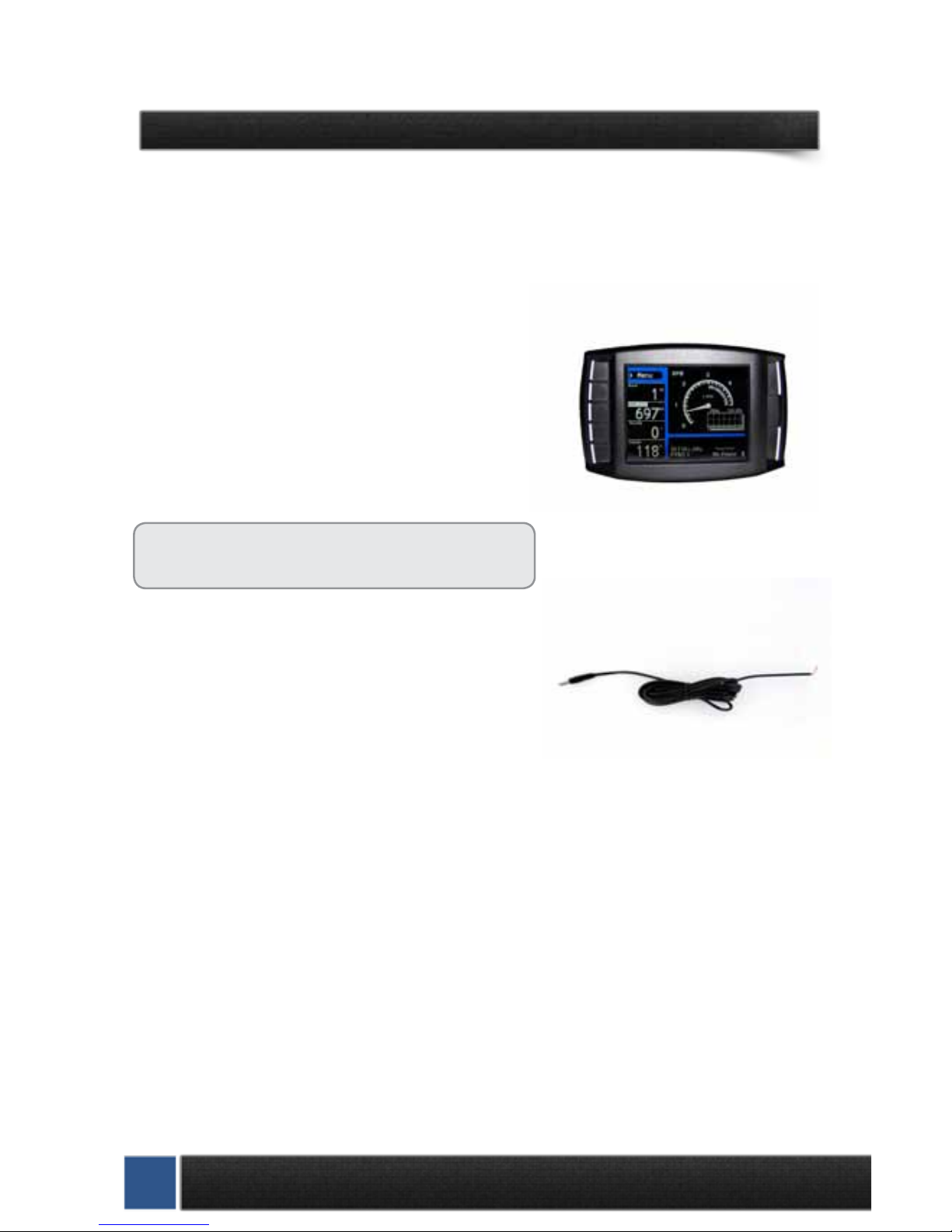
The Mini Maxx Head Unit
The main component is the Mini Maxx Head Unit. The Head
Unit is the interface in which you control vehicle performance parameters. It is also the brains that will save vehicle
activity and defuel a vehicle. Notice that the head unit has:
seven total buttons, ve on the left side and two on the right,
a large color screen, and an electronic plug for docking on
the back. Note that this is the last piece that you will install.
Note: Mini Maxx includes a micro SD card inserted
in the side of the Head Unit.
Power Cable
The Power cable connects the OBD ll Adaptor Plug to the vehicle fuse box to supply power to the Mini Maxx. It is optional
to use as there are two ways to power up your Mini Maxx
1. (Recommended) Use this power cable and wire it to the
designated location specied later in this manual.
2. The OBD II port provides constant 12V+ power, so your Mini Maxx can power o of the OBD II
port alone. But in this situation the Mini Maxx will not turn on and o with the ignition. There is
a switch on the OBD II adapter plug in order to turn the Mini Maxx on and o.

1-888-628-1730 • Mini Maxx Installation Manual 7
Universal Windshield Mount
This universal windshield mount is used to install the
Mini Maxx rmly onto the windshield, it is a suction
cup mount that will work on any vehicle windshield.
Check our web site for other mounting options, the
Mini Maxx is adaptable to a range of other mounting
styles.
H&S Also oers custom vehicle specic solutions. See www.hsperformance.com for details.
OBD II Adapter Plug
The OBD II Adapter is a communication hub for the Mini Maxx.
The OBD ll Adaptor plugs directly into the vehicle OBD ll port.
Notice the OBD ll Adaptor has many ports to support various
other functions of the Mini Maxx.
8 Mini Maxx Installation Manual • www.hsperformance.com
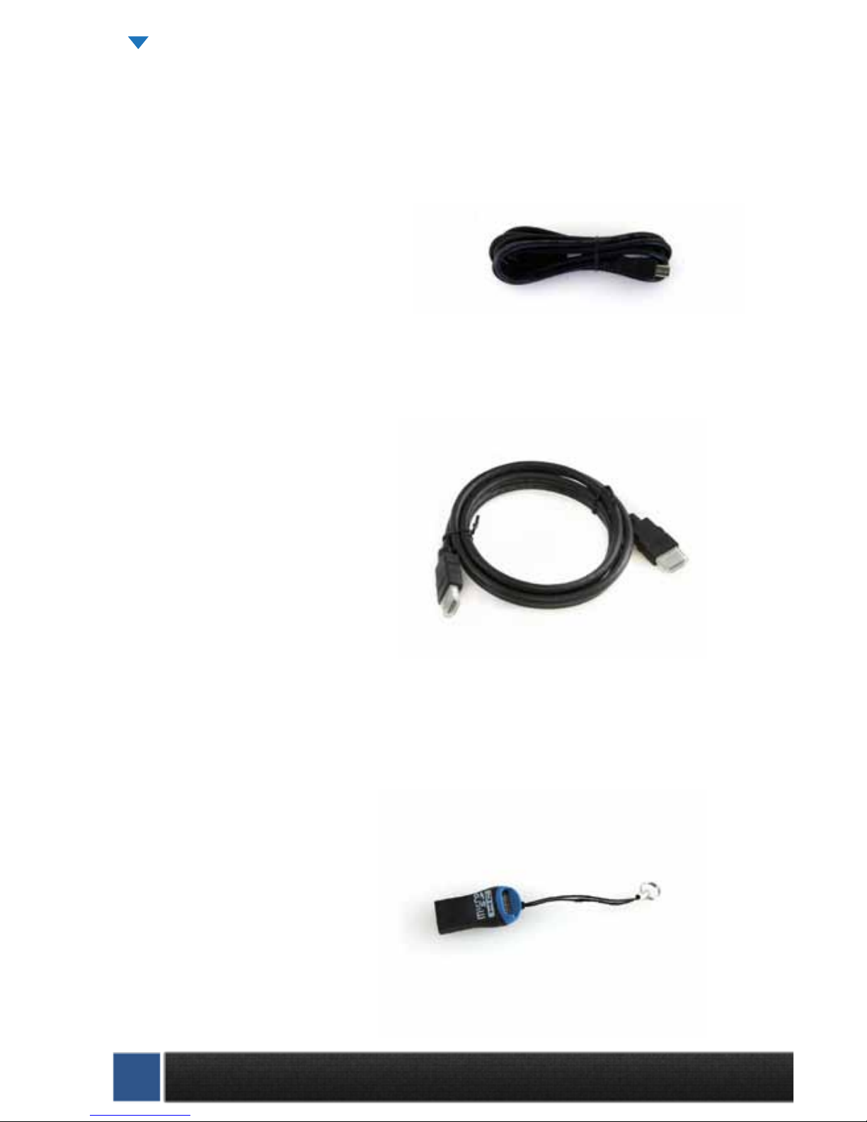
Mini USB Cable
Use this cable to connect your Mini Maxx to your personal computer to install software updates. Visit
www.hsperformance.com in the downloads section for product updates. Please nd your product application and follow the posted instructions there to update your Mini Maxx.
HDMI Cable
The HDMI Cable connects the Mini Maxx to the OBD ll Adapter Plug and acts as the main line of communication for the Mini Maxx.
USB to Micro SD Adapter
The USB to Micro SD Adapter is what you will use to update your Mini Maxx. You will take the Micro
SD card out of the Mini Maxx and insert it into the adapter, then insert the adapter into your personal
computer.
PARTS DESCRIPTION CONTINUED
1-888-628-1730 • Mini Maxx Installation Manual 9
Mini Maxx & Windshield Mount
OBD II Adapter Plug
OBD II Port
Power Cable
(Optional)
Fuse Box
Fire wall grommet
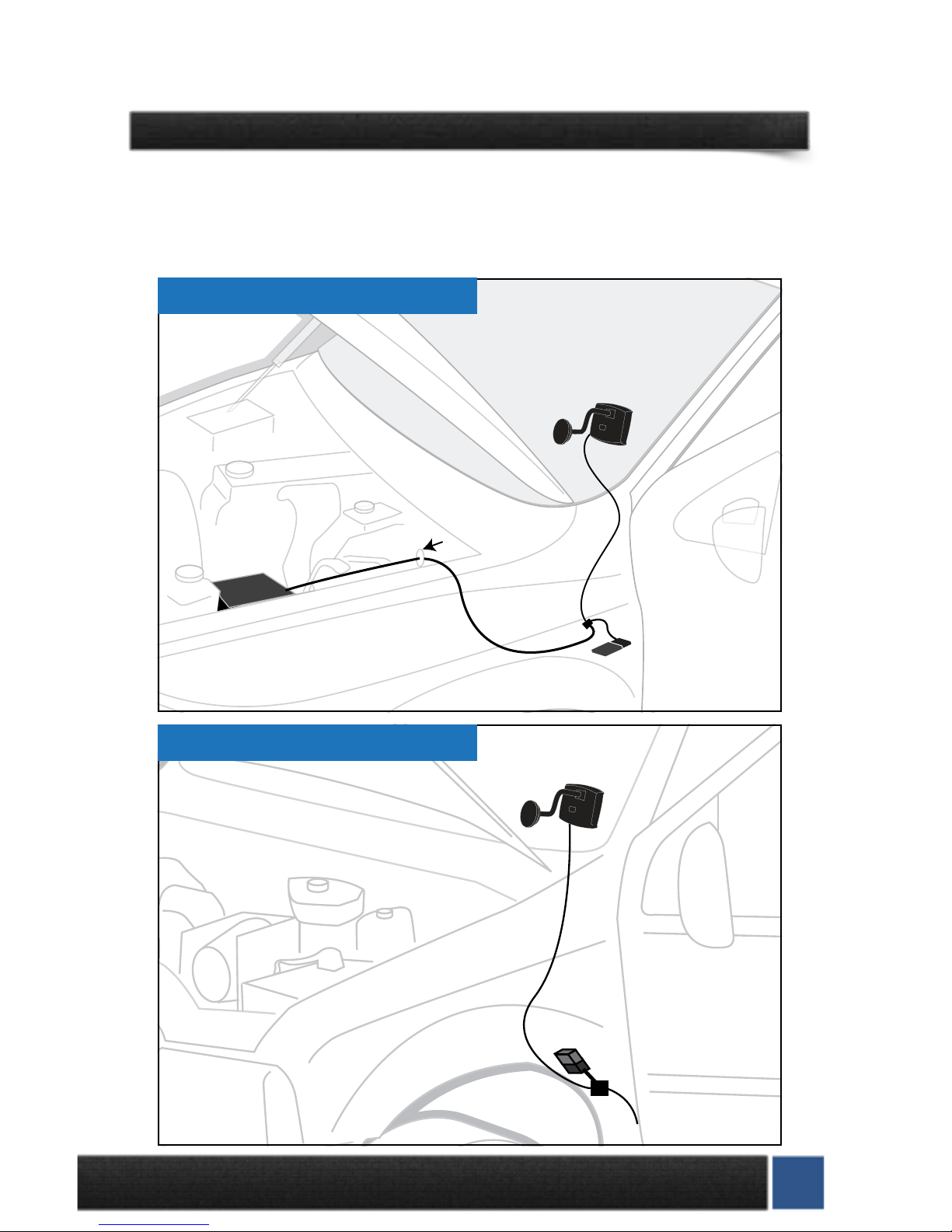
MOST APPLICATIONS
INSTALLATION OVERVIEW
The installation overview illustrates a totally installed and functional Mini Maxx system. This overview is
meant to help reference the general location of installed parts and pieces of the Mini Maxx. Notice that there
are dierent overview diagrams. Use the correct diagram for your truck. For more complete wiring diagrams
and instructions, please see vehicle specic features starting on page 27.
OBD II Port
OBD II Adapter Plug
Power Wire
(Optional. To purple
ignition
wire under dash)
MINI MAXX &
Windshield mount
HDMI Cable
FORD POWER STROKE ‘08’10

10 Mini Maxx Installation Manual • www.hsperformance.com
MINI MAXX INSTALLATION INSTRUCTIONS
SECTION 1: MOUNTING THE MINI MAXX
In this section you will decide where to mount the Mini Maxx Cradle, so you are essentially choosing the location for the Mini Maxx inside the vehicle cab. First, decide which mounting style you will choose for the Mini
Maxx; we oer two dierent styles of mounting:
1. Windshield mounting
2. Custom Pod mounting (Refer to the instructions included with your custom pod)
Visit www.hsperformance.com for custom options
INSTALLATION CONTINUED
WINDSHIELD MOUNTING
1. Locate the T-shaped mount socket on the back side of the Mini Maxx.
2. Notice that the top of the universal mount will t into T-shaped socket and slide forward to
secure the Mini Maxx to the mount.
3. With the Mini Maxx connected to the mount use the windshield mount to secure the Mini Maxx
to the wind- shield. Be sure that the position of the Mini Maxx does not obstruct the view of
the road or distract the driver from their primary responsibility, which is driving responsible.

1-888-628-1730 • Mini Maxx Installation Manual 11
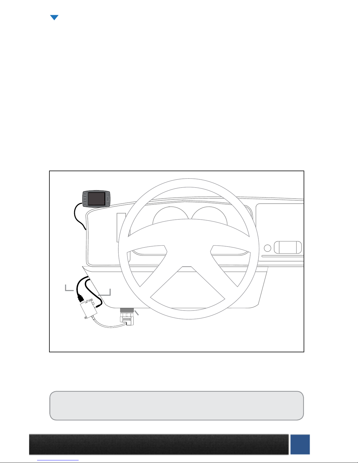
SECTION 2: OBD II ADAPTER PLUG
This step involves locating the vehicle’s OBD ll port and
then simply plugging the OBD ll Adapter Plug into the
OBD ll port.
1. As the illustration below shows, OBD ll ports
are always located somewhere under the drivers side dash. The OBD ll port is a male receiver
that will have the same shape as the end of the
OBD ll Adaptor plug.
2. Once the OBD ll port is located, then simply
plug the OBD ll Adaptor plug into the OBD ll
port.
OBD II ADAPTER PLUG DIAGRAM
1. OBD ll Male end: this is the part of the adapter plug that plugs into the vehicle OBD ll port.
2. Main harness port:
the main harness will plug into the Mini Maxx and into this port during installation.
3. Power wire port: the power wire will run from this port to the vehicle fuse box during installation.
Plug into the Mini Maxx and into this port during installation.
4. Power supply switch: use this switch to change power from battery power to keyed power for a
powered supply for the Mini Maxx.
5. Four pin usb: This port is used if an H&S pyrometer kit is purchased for the Mini Maxx.
6. Five pin usb
7. Adapter plug fuse
Possible OBDII Port Locations
(location may vary)
Note: On some vehicles it is recommended to move the OBD II port to a safer location. Because the Mini Maxx will
remain plugged in, the adapter can be kicked/bumped and broken. Please move your OBD II connection to a safer
location if you feel it is in a position that may allow it to get damaged.
KEY BAT T
7
3
1
4
2
5 6

12 Mini Maxx Installation Manual • www.hsperformance.com
SECTION 3: INSTALLING THE POWER WIRE *OPTIONAL
*The OBD II port provides constant 12V+ power, so your Mini Maxx can power o of the OBD II port alone.
But in this situation the Mini Maxx will not turn on and o with the ignition. There is a switch on the OBD II
adapter plug in order to turn the Mini Maxx on and o.
In this section you will run the Power Wire coming from the Mini Maxx Cradle to the vehicle fuse box and
connect it to the fuse locations specied below. The fuse location for the Power Wire is dierent on each
vehicle application.
CONNECTING THE POWER WIRE:
1. Route wire to location shown in pictures found in the Vehicle Specic Sections starting on page 27
2. Remove the fuse, indicated in the pictures, and insert the fuse jack. Make sure that the fuse jack is placed
on the dead side of the fuse to ensure that the Mini Maxx is protected by the fuse. Use a volt meter to verify
the dead side of the fuse. With the fuse pulled and the truck powered on but not started, the volt meter
should read 0 volts on the fuse jack to ground. Problems that can occur if the incorrect fuse is used for
this connection: the power may stay on continuously even with the key o; or, the Mini Maxx can receive
power at the incorrect time of the power-on/starting cycle of the vehicle.
3. Run the power wire through the re wall before preparing the Power Wire. Prepare the Power Wire by
stripping the end of the wire about ¼”. Connect the blue 90° connector to the end of the Power Wire using
crimping pliers.
4. Connect the Power Wire to the fuse jack, place the fuse back into the slot, and close the fuse box.
1-888-628-1730 • Mini Maxx Installation Manual 13
SECTION 4: RUN MINI MAXX HDMI CABLE
In this section you will connect the Mini Maxx HDMI cable to the OBD ll Adaptor plug and then run the other
end of the HDMI cable up the side of the vehicle dash and connect it to the back of the Mini Maxx.
1. Plug one end of the HDMI cable into the Main Harness port on the OBD ll adapter plug.
2. Run the other end of the HDMI cable up through the vehicle dash on the drivers side so that the end of
the cable emerges from the dash near the vehicle A-pillar. It may be necessary to temporarily remove
the vehicle weather stripping and dash panel to achieve an installation where the HDMI cable cannot
be seen.
3. Plug the HDMI cable into the back side of the Mini Maxx, make sure that there is enough slack in the
cable to accommodate mounting the Mini Maxx to the windshield.
Almost Done!
You need to install the download now. Read the next section for Install Download procedure.
INSTALLATION CONTINUED
OBD II Plug
Mini Maxx
Power Cable
HDMI Cable
14 Mini Maxx Installation Manual • www.hsperformance.com
MINI MAXX OPERATING INSTRUCTIONS
These operating instructions are split into sections:
•SECTION 1: Button Navigation
•SECTION 2: Install Download
•SECTION 3: Exploring the Main Screen
•SECTION 4: Exploring the Menu System
•SECTION 5: Vehicle Setup
•SECTION 6: Other Mini Maxx Features
•SECTION 7: Vehicle Specic Features
•SECTION 8: Unplugging the Head Unit
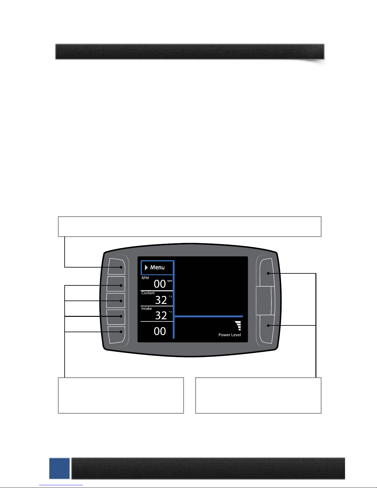
SECTION 1: BUTTON NAVIGATION
Press the top left button to enter the Main Menu, also use this button to exit menus.
Press any of the four buttons on the left to
select items on the screen that are adjacent to
the button position.
In general these buttons work as up and down
buttons, they may also be used to select items
on the screen adjacent to these buttons.
Speed
MPH

1-888-628-1730 • Mini Maxx Installation Manual 15
SECTION 2: INSTALL DOWNLOAD
The Install Download option is used to install tuning onto a vehicle, or return a vehicle to stock.
1. Press Menu: To get into the Mini Maxx main menu.
2. Select Install Download: You may have to “Arrow Down” or “Arrow Up” to nd this option.
3.
Install a download onto a stock vehicle: If the vehicle is stock and you enter the install download
menu, simply follow the screen prompts to install a download on the vehicle. This is the point in which you
may come across the tire size calibration menu, and the vehicle speed limiter menu
Download H&S Tuning: This option will install the H&S Performance tuning to your truck. Custom
tuning options can be downloaded from H&S or may be available as options during the installation
process.
Import/Export MCC Tuning: This option will allow import or export of MCC software tuning les.
Some vehicle may not have this option. See www.hsperformance.com/mcc for more info.
Return to stock (OEM tune): This option will return the vehicle to its factory software level and un-
lock the H&S device. This is highly recommended if taking the vehicle in for service or maintenance..
NOTE: Returning to stock is required in order to install your tuner on another vehicle.
This Mini Maxx screen shot shows what you will see if a download has already been entered into a vehicle.
Before installing the download:
•MakesurethattheMiniMaxxisproperlypluggedin.
•Makesurethattheharnessisproperlyinstalled.
•Thevehiclebatteryisfullycharged.
•Thevehicleiswarmeduptooperatingtemperature.
THE MICRO SD CARD MUST BE INSERTED IN THE SIDE OF THE MINI
MAXX TO DOWNLOAD TO A VEHICLE.
Go Back
DOWNLOAD MENU
Import/Export MCC Tuning
Return to Stock (OEM Tune)
Download H&S Tuning
(RESET)
16 Mini Maxx Installation Manual • www.hsperformance.com
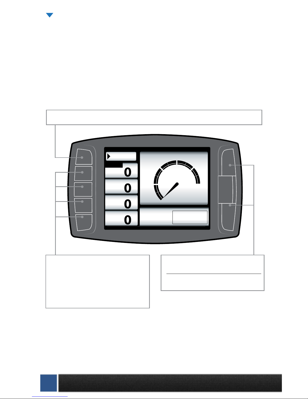
SECTION 3: EXPLORING THE MAIN SCREEN
The Main Screen is where you view all of the vehicle activity. In this section you will learn how to navigate
the Main Screen and learn about all of the dierent parts of the Main Screen.
MAIN SCREEN NAVIGATION
Below are descriptions of how all of the Mini Maxx buttons work and what they do while in the Main
Screen. The buttons perform dierent functions while in a menu or submenu.
Speed
MPH
RPM
RPM
Coolant
ºF
Throttle
X
Menu
MPH
0
30
60 120
90
Power Level Setting
not available until
download is installed.
Press any of the four buttons on the left that
coincide with the four vehicle parameters to
display that particular vehicle parameter on the
large gauge in the upper right side of the screen.
Hold a button down to view the dierent graph
types for the large gauge.
Power Level Up
Power Level Down
Use the power level buttons to control power
levels on-the-y only while in the main screen
Press the top left button to enter the Main Menu, also use this button to exit menus.
Mini Maxx OPERATION CONTINUED
1-888-628-1730 • Mini Maxx Installation Manual 17
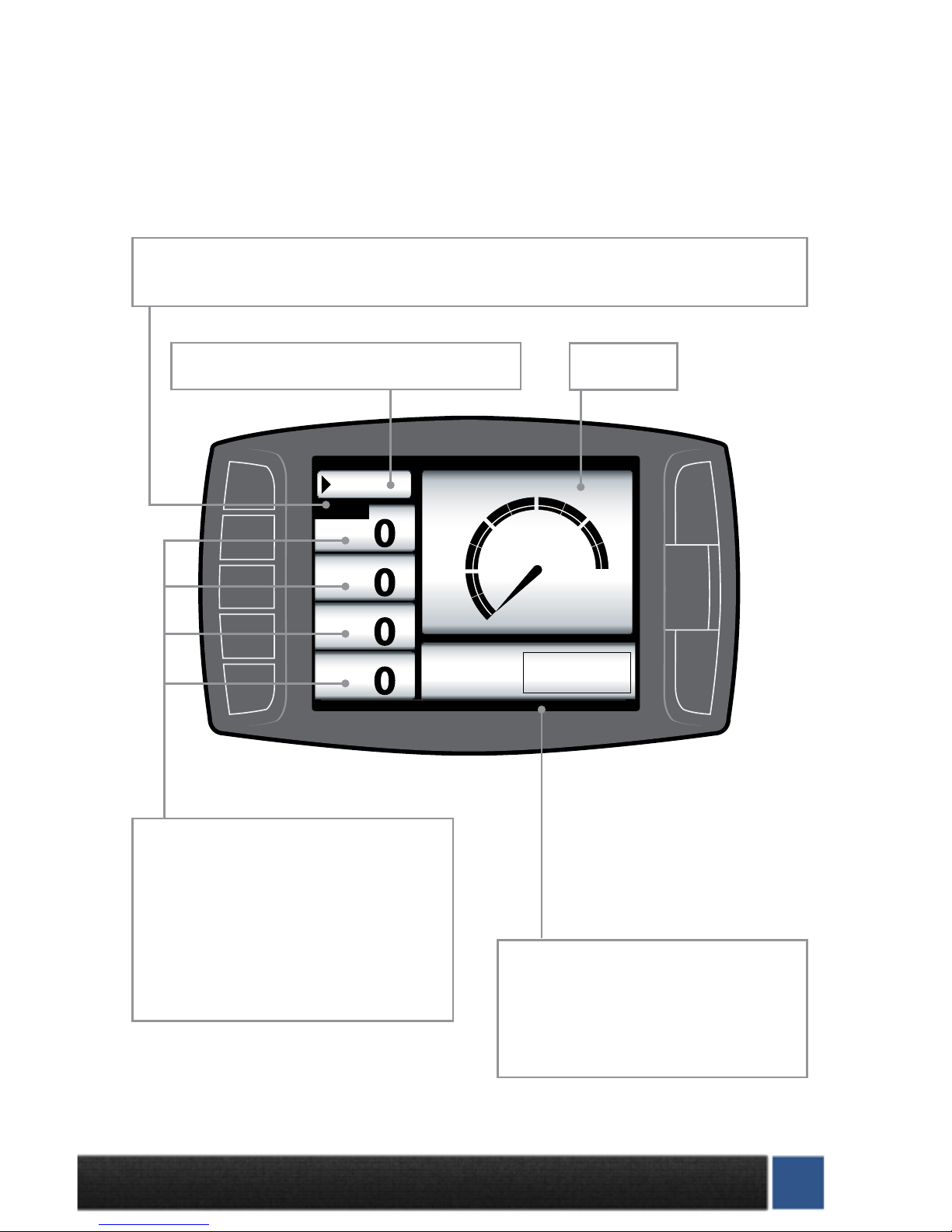
MAIN SCREEN PARTS DESCRIPTION
This section will describe all of the dierent parts of the Main Screen.
Speed
MPH
RPM
RPM
Coolant
ºF
Throttle
X
Menu
MPH
0
30
60 120
90
Power Level Setting
not available until
download is installed.
Large Gauge
Vehicle parameters: To change which vehicle
parameter is displayed in the large gauge area
simply press one of the four buttons next the
preferred vehicle parameter.
By pressing and holding the button next to your
displayed gauge, you can change the display
style in the large gauge area.
Menu button: press to enter the main menu.
Power level text: Displays which power level is
active, whether it be: Stock, Tow, Street, or Hot.
Note: This will not be active if the Download has
not been installed.
The black bar: The black bar highlights the title of one of the four displayed vehicle parameters to indicate
that vehicle parameter is also being displayed on the large gauge.

18 Mini Maxx Installation Manual • www.hsperformance.com
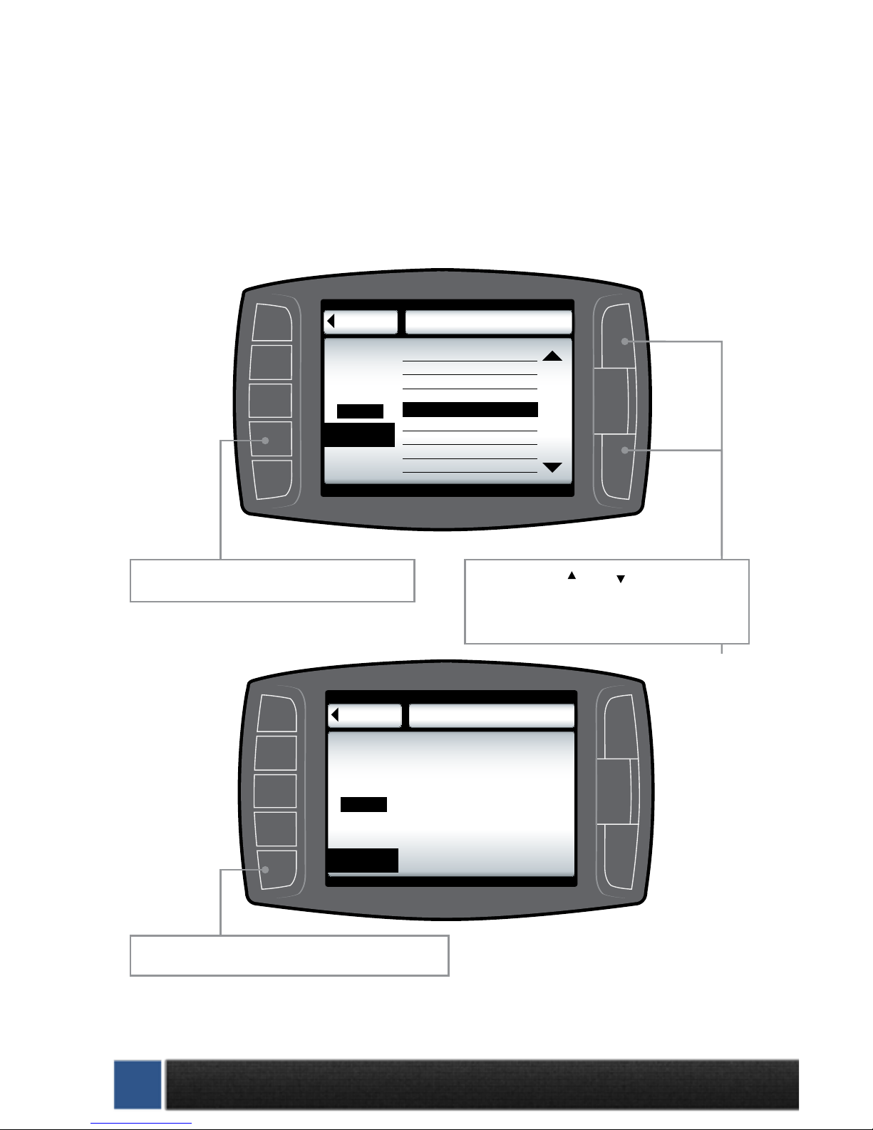
Go Back
MAIN MENU
to Main Screen
Install Download
Gauge Set Up
Set User Options
Set Defuel Levels
Adjust Tire Size
Diagnostics
Show Settings
Update Firmware
Navigation through the main menu: Use the
large Up Down Buttons to page up and
page down through all the Main Menu options.
These buttons are used
to enter into the sub
menus from the main
menu and may also be
used to select additional
items when in the sub
menus.
This button is used to enter into the Main Menu
from the main screen. While in any of the menus
this button works as a back button.
Mini Maxx OPERATION CONTINUED
SECTION 4: EXPLORING THE MENU SYSTEM
The diagram below shows all of the Main Menu items and explains the Main Menu navigation.

1-888-628-1730 • Mini Maxx Installation Manual 19
DEFUELING PARAMETERS
Set up defueling parameters based on a number of dierent vehicle parameters. In this menu you
can also turn vehicle parameters o. The defueling parameters available are vehicle specic, so not
all defueling parameters are available for every make and model.
Here is a list of all of the defueling capabilities
for the Mini Maxx. All defueling options can be
activated at the same time, all can be turned o,
or a mix of on and o. Each defueling option is
adjusted individually to be on or o and set to a
particular defueling temperature.
Engine Coolant Temp Level
Boost Level
Go Back
DEFUEL MENU
Transmission Temperature
Oil Temperature
Pyro 1 Temperature Level
Pyro 2 Temperature Level
to Main Menu
Setting: 600˚F
Setting: 1250˚F
Setting: 210˚F
Setting: 260˚F
Setting: 210˚F
Setting: 23PSI
Use the Up Down Buttons to scroll up and
down through the dierent sub menu items.
Press to enter set up menu for defuel items.
Default Defueling Settings
Pyro 1 Temperature Level 1450˚F
Pyro 2 Temperature Level OFF
Engine Coolant Temp Hot 210°F
Engine Coolant Temp Cold
(cold start protection)
OFF
Boost Level OFF
Transmission Temp Level OFF
Oil Temperature OFF
Current setting are displayed in Defuel Menu
SECTION 5: VEHICLE SETUP
This section describes various non-vehicle specic features of the Mini Maxx
INSTRUCTIONS CONTINUED
20 Mini Maxx Installation Manual • www.hsperformance.com
SET DEFUEL LEVELS
When entering a setup menu for any of the defuel options the menu will have a list of defuel levels
to select from based on that specic defuel parameter. The selected value is displayed on the left, to
select a defuel level you need only highlight the amount and then exit the setup menu. To turn any
particular defuel parameter o press the bottom left button.
Go Back
PYRO1
to Defuel Menu Set Deful Level
The selected defuel value
for PYRO 1 is displayed
in the box below:
Selected
OFF
DEFUEL OFF
DEFUEL ON
Go Back
PYRO1
to Defuel Menu Set Deful Level
up
down
Defueling Levels
1250
1300
1350
1400
1450
1500
1550
1600
The selected Defuel value
for PYRO 1 is displayed
in the box below:
Selected
1400º F
DEFUEL ON
DEFUEL OFF
Use the large Up Down Buttons to scroll up
and down through the dierent sub menu items.
Use this button to turn the defueling on.
Use this button to turn the defueling off.
 Loading...