

Page 1
INSTALLATION AND
OPERATING INSTRUCTIONS
OWNERS MANUAL
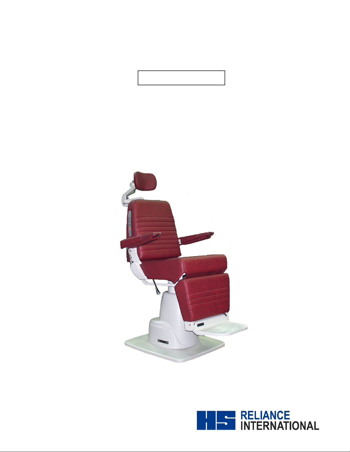
MODEL 6200
LOW VOLTAGE CONTROL CHAIR
Page 2

SERIAL NUMBER
For your future reference, mark the serial number
in the space provided.
QUALITY MANAGEMENT
SYSTEM
REGISTERED TO
ISO 9001:2008
ISO 13485:2003
MADE I N AM ER IC A
Reliance® Medical Products • 3535 Kings Mills Road • Mason, Ohio 45040-2303 • 1-800-735-0357 • www.reliance-medical.com
Page 3

TABLE OF CONTENTS
4. LOCATING AND REPLACING FUSES..........................11
IMPORTANT INFORMATION.............................................4
1. INTRODUCTION.........................................................5
TECHNICAL SPECIFICATIONS.........................................6
2. INSTALLATION...........................................................7
2.1. Unpacking.......................................................7
Chair......................................................................7
2.2. Assembly.........................................................7
Headrest......................................................................7
Power Receptacle...................................................7
3. OPERATION..............................................................7
3.1. Stop Switch.....................................................7
3.2. Chair Lift........................................................8
Rais ing & Low erin g the Cha ir Lift fro m the
Footswitch...............................................................8
3.3. Chair Top........................................................9
4.1. Fuse Replacement..........................................11
TROUBLESHOOTING GUIDE..........................................12
CLEANING AND MAINTENANCE ....................................13
PARTS LIST.................................................................14
Model 6200 Chair Assembly..................................15
Chair Top Assembly...............................................16
Chair Base Assembly.............................................20
Lift Assembly.........................................................22
#18, 22 Headrest Assembly...................................24
#10 Headrest Assembly.........................................26
#11 Headrest Assembly.........................................28
#21 Headrest Assembly.........................................30
Wiring Diagram - 6200 .........................................32
LIMITED WARRANTY.....................................................35
Posistioning the Chair Back.....................................9
3.4. Revolving/Rotation..........................................9
3.5. Arm Movement................................................9
3.6. Footrest..........................................................10
3.7. Headrest.........................................................10
Operation-No. 18, 22 Headrest................................10
Adjustment-No. 18, 22 Headrest............................10
Operation-No. 10 Headrest....................................10
Operation-No. 11, 21 Headrest..............................10
Adjustment-No. 11, 21 Headrest............................11
IN-6200
3
Page 4
IMPORTANT INFORMATION
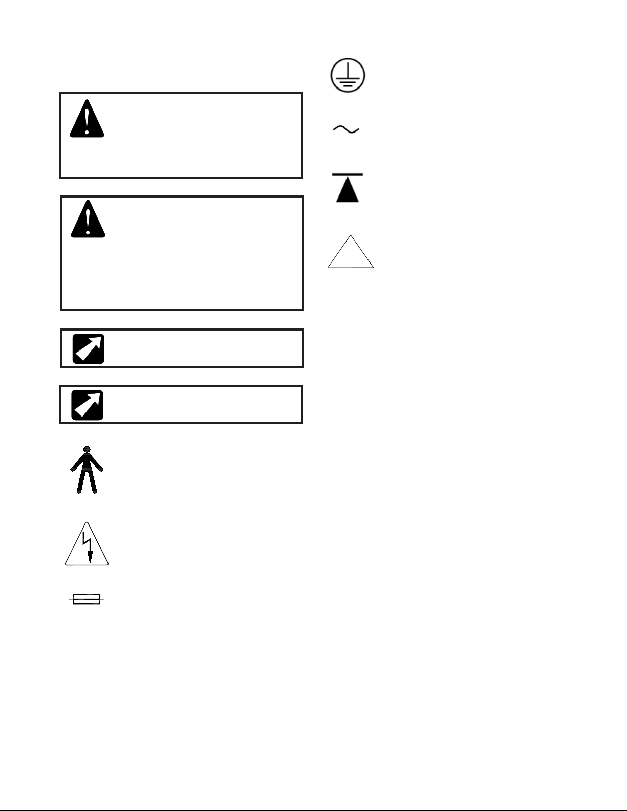
SAFETY SYMBOLS
Protective Earth Ground
“DANGER”, “WARNING”, or “CAUTION”
The exclamation point within an equilateral
triangle is intended to alert the user to
the presence of important operating and
maintenance (servicing) instructions in this
Installation and Operating Instructions.
« DANGER », « AVERTISSEMENT », ou
«PRÉCAUTION »
Le point d’exclamation à l’intérieur d’un
triangle équilatéral vise à alerter l’utilisateur
à la présence d’importantes instructions
de fonctionnement et de maintenance
(service) dans ce manuel d’installation et
d’instructions de fonctionnement.
“NOTE”
Amplifies a procedure, practice, or condition.
“NOTE”
Amplifie une procédure, pratique ou condition.
Type B, Applied Part
Alternating Current-AC
Safe Working Load
“Attention, Consult Accompanying
Documents”
!
TRANSPORTATION / STORAGE CONDITIONS
Temperature: Operating: 59 to 104º F
15 to 40º C
Storage: -22 to +140º F
-30 to +60º C
Relative Humidity: Operating: 5%RH to 95%RH
without condensation
Storage: 10%RH to 100%RH,
including condensation
Atmospheric Pressure: Operating: 700hPa - 1060hPa
Storage: 500hPa - 1060hPa
Dangerous Voltage / Shock Hazard
Fuse Rating Specification
IN-62004
Page 5

1. INTRODUCTION
1.1. This manual contains information applicable only
to the Reliance® Model 6200 Chair.
1.2. Whenever you see the symbols shown below,
heed their instructions! Always follow safe operating
and maintenance practices.
“DAN GE R”-
IDENTIFIES SPECIAL INSTRUCTIONS OR
PROCEDURES WHICH, IF NOT CORRECTLY
FOLLOWED, COULD RESULT IN LOSS OF
LIFE OR PERSONAL INJURY.
THE DANG ER SYMBO L
« DANGER » : LE SYMBOLE DANGER
ID ENT IF IE DE S I NST RU CTI ON S O U
PROCÉDURES SPÉCIALES QUI, SI ELLES
NE SONT PAS SUIVIES CORRECTEMENT,
POURRAIENT CAUSER UNE PERTE DE VIE
OU UNE BLESSURE.
“WARNING”-
IDENTIFIES SPECIAL INSTRUCTIONS
OR PROCEDURES WHICH, IF NOT
CORRECTLY FOLLOWED, COULD RESULT
IN PERSONAL INJURY.
THE WARNING SYMBOL
« AVERTISSEMENT » : LE SYMBOLE
AV E R T I S S EM EN T ID E N T I F I E DE S
INSTRUCTIONS OU PROCÉDURES SPÉCIALES
QUI, SI ELLES NE SONT PAS SUIVIES
CORRECTEMENT, POURRAIENT CAUSER
UNE BLESSURE.
“CAUTION”-
special instructions or procedures which,
if not strictly observed, could result in
damage to or destruction of equipment.
This caution symbol identifies
“NOTE”-
additional information.
Note indicates points of particular or
« REMARQUE » : Remarque indique des points
d’intérêt particulier ou des renseignements
additionnels.
d’information particulière ou supplémentaire.
1.3. Should your product not perform properly, or if
you have any questions concerning the use and care
of any Reliance® product, contact the Reliance®
Distributor, where you purchased this product or contact
the Technical Service Department, Reliance® Medical
Products, Inc., 3535 Kings Mills Road, Mason, Ohio
45040-2303, or call (800) 735-0358.
NOTE:
serial number available before contacting
Reliance® or your Authorized Reliance®
Distributor.
la note indique des remarques
Always have the model number and
REMARQUE : Ayez toujours le numéro de
modèle et le numéro de série à portée de la
main avant de contacter Reliance® ou votre
distributeur Reliance® autorisé.
“CLASSIFIED BY CANADIAN STANDARDS
ASSOCIATION® WITH RESPECT TO ELECTRIC
SHOCK, FIRE AND MECHANICAL HAZARDS
ONLY IN ACCORDANCE WITH UL 60601-1.”
According to Clause 5 in IEC 60601-1, sec 6.8.1, this
unit is classified by the following:
• The type of protection against electric shock:
EQUIPMENT energized from an external electrical
power source: CLASS I EQUIPMENT
• The degree of protection against electric shock:
TYPE B EQUIPMENT
IN-6200
« PRÉCAUTION » : Ce symbole de
précaution identifie des instructions ou
procédures spéciales qui, si elles ne sont pas
strictement suivies, pourraient causer un
dommage ou la destruction de l’équipement.
• The degree of protection against harmful ingress of
water: ORDINARY DEGREE
• The degree of safety of application in the presence
of a FLAMMABLE ANAESTHETIC MIXTURE WITH AIR
or WITH OXYGEN OR NITROUS OXIDE: EQUIPMENT
not suitable for use in the presence of a FLAMMABLE
ANAESTHETIC MIXTURE WITH AIR or WITH OXYGEN
OR NITROUS OXIDE
• The mode of operation: CONTINUOUS OPERATION
5
Page 6
WARNING: TO PREVENT FIRE OR ELECTRICAL
SHOCK HAZARD, DO NOT EXPOSE THIS
EQUIPMENT TO RAIN OR MOISTURE.
AVERTISSEMENT : POUR ÉVITER UN
IN CENDIE OU U N RIS QU E DE CH OC
ÉL E CTR I QUE , N’ E XPO S EZ PA S CE T
ÉQUIPEMENT À LA PLUIE OU À L’HUMIDITÉ.
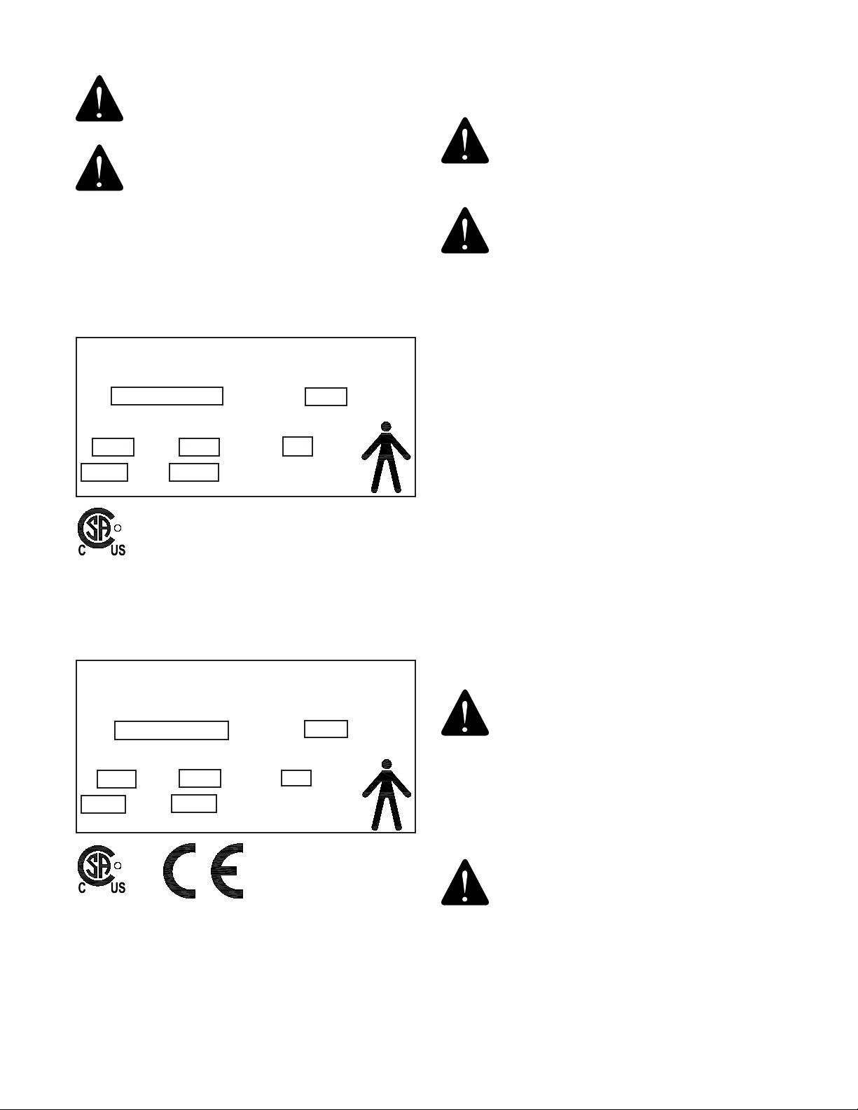
TECHNICAL SPECIFICATIONS
Rating for 120V Low Voltage Chair
This equipment is rated Class I, Type B
Equipment Model
Low Voltage Chair 6200
Volts Hertz Amps
120V 50/60 8.0
Class I Type B
IMPORTANT USER WARNINGS
WARNING: EXPLOSION HAZARD. THIS EQUIP-
MENT MUST NOT BE USED IN THE PRESENCE
OF FLAMMABLE ANESTHETICS.
AVERTISSEMENT : RISQUE D’EXPLOSION.
CET ÉQUIPEMENT NE DOIT PAS ÊTRE UTILISÉ
EN PRÉSENCE D’ANESTHÉSIQUES INFLAMMABLES.
POT ENTIAL ELEC TROMAGNETIC or OTHER
INTERFERENCE
This equipment generates, uses and can radiate radio frequency
energy and, if not installed and used in accordance with the
instructions, may cause harmful interference to other devices
in the vicinity. However, there is no guarantee that interference
will not occur in a particular installation.
If this equipment does cause harmful interference to other
devices, which can be determined by turning the equipment off
and on, the user is encouraged to try to correct the interference
by one or more of the following measures:
• Reorient or relocate the receiving device.
Rating for 230V Low Voltage Chair
This equipment is rated Class I, Type B
Equipment Model
Low Voltage Chair 6200
Volts Hertz Amps
230V 50 3.0
Class I Type B
U.S. Patent No.
3,661,421
3,792,905
5,467,002
• Increase the separation between the equipment.
• Connect the equipment into an outlet on a circuit different
from that to which the other device(s) are connected.
• Consult the manufacturer or field service technician for
help.
WARNING - STORAGE OF THIS EQUIPMENT
BELOW 40°F (4.4ºC) WILL CAUSE THE
HYDRAULIC OIL TO BECOME THICK. THIS
MAY CAUSE UNU SUAL NOISES WHEN
THE BASE MOTOR IS OPERATED. IT IS
RECOMMENDED THAT THE EQUIPMENT
STAY AT A TEMPERATURE OF 60°F (15.6ºC)
OR ABOVE FOR AT LEAST 8 HOURS BEFORE
OPERATING.
AVERTISSEMENT : L’ENTREPOSAGE DE
CET ÉQUIPEMENT À MOINS DE 4,4°C (40°F)
FERA EN SORTE QUE L’HUILE HYDRAULIQUE
DEVIENDRA ÉPAISSE. CECI POURRAIT
CAUSER DES BRUITS INHABITUELS LORSQUE
LE MOTEUR DE LA BASE FONCTIONNE. ON
RECOMMANDE QUE L’ÉQUIPEMENT DEMEURE
À UNE TEMPÉRATURE DE 15,6°C (60°F) OU
PLUS DURANT AU MOINS 8 HEURES AVANT
DE L’UTILISER.
IN-62006
Page 7
2. INSTALLATION
2.1. Unpacking
2.1.1. Chair
2.1.1.1. Cut the shipping bands, open the top of the
shipping carton, and remove all packing material and boxes
that can be easily reached. Remove (4) nuts and remove
both base clamping boards.
2.1.1.2. It is recommended that the skid be positioned as
close as possible to the desired chair location.
2.1.1.3. Remove at least two small shipping blocks stapled
to the top of the skid. The chair can now be slid and/or
tipped from the skid onto the floor.
2.1.1.4. Do not lift the chair by the upper structure.
However, the chair may be tipped or slid into position by
pushing or pulling on the upper structure.
2.1.1.5. With the chair in positon, remove all remaining
paper pads, plastic, tape, strings, etc.
2.2. Assembly
2.2.2.2. To disconnect power to Chair unplug power cord
from Instrument Stand or from wall receptacle.
NOTE: If this chair is purchased in conjunction
with a Reliance® instrument stand, the chair control
cable supplied will provide proper operation. Refer
to the instrument stand manual for connection to
the stand.
REMARQUE : Si cette chaise est achetée avec
un support à instruments Reliance®, le câble
de commande de la chaise fourni permettra un
fonctionnement adéquat. Se référer au manuel du
support d’instrument pour savoir comment faire la
connexion au support.
3. OPERATION
CAUTION: Caution should be taken to ensure
there are no obstructions (instruments, trays,
tables) impeding movement of the Chair.
PRÉCAUTION : On devrait faire attention
pour s’assurer qu’il n’y a pas d’obstructions
(instruments, plateaux, tables) empêchant le
mouvement de la chaise.
2.2.1. Headrest
2.2.1.1. Remove the headrest from its carton, and mount
it into position onto the chair back. Using the proper hex
key wrench, tighten the cap screw to clamp the headrest
securely into its mounting bracket.
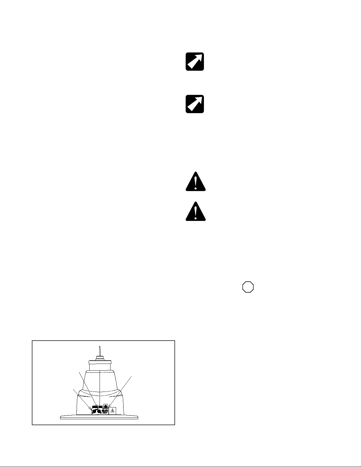
2.2.2. Power Receptacle
2.2.2.1. Locate the footswitch assembly, chair control
cable, and the power cord assembly. Refer to Figure 1 for
receptacle location and attach all cables.
Footswitch
Cable
Chair Control
Cable
Power Cord &
Fusedrawer
Each time main power is applied to the chair, the circuit
board inside the chair will respond with a one second
beep. The beep indicates the electronics are functioning
properly.
3.1. Stop Switch
3.1.1. Depressing the STOP switch on either side of the chair
back will STOP ALL movement of the chair. The STOP switch
is shaped like a stop sign, and should be ORANGE in color. It
is located above the text “STOP”. (Refer to Figure 2).
IN-6200
FIGURE 1
BASE
7
Page 8
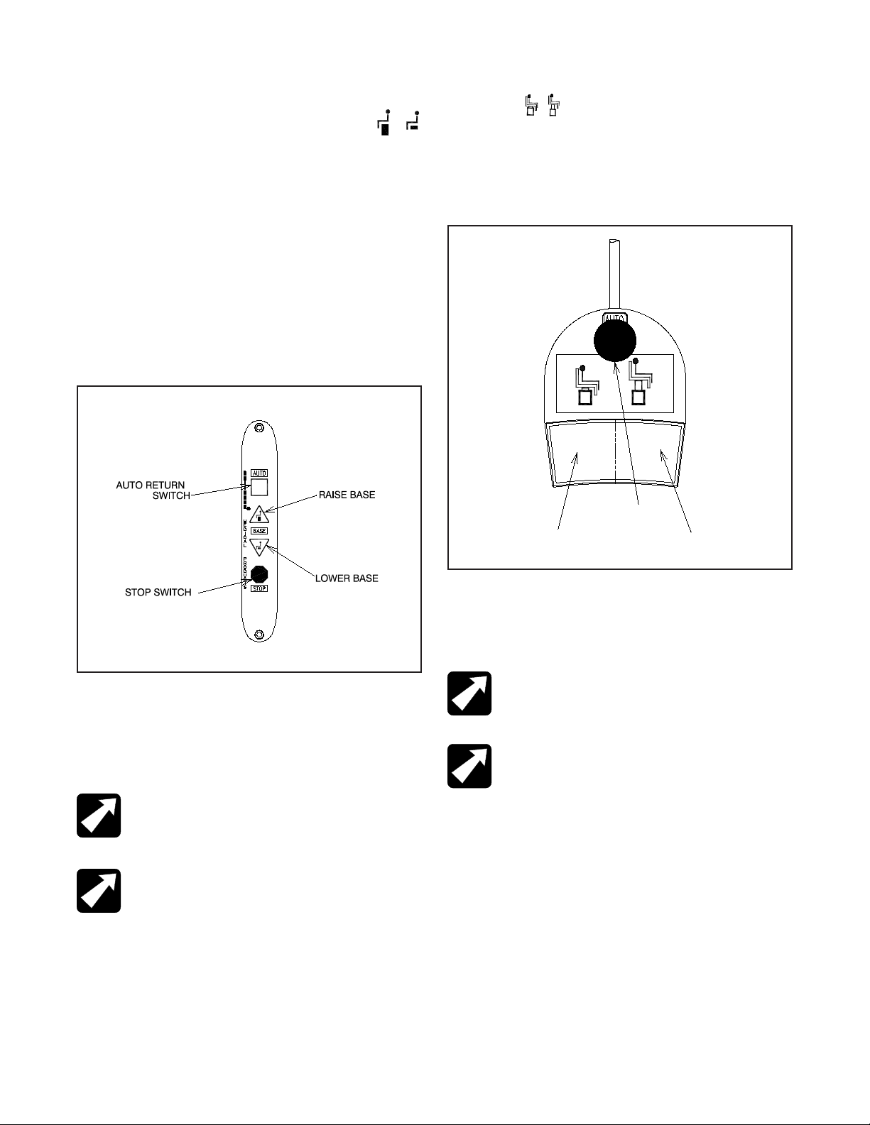
3.2. Chair Lift
3.2.1. Raising & Lowering the Chair Lift with
Membrane Switches
• The chair lift may be raised or lowered by Membrane
Switches on either side of the chair back (Figure 2).
• To raise the chair lift from these switches, depress the
triangular-shaped UP arrow located ABOVE the text ”BASE”.
This is called the RAISE BASE switch.
• To lower the chair lift, depress the triangular-shaped DOWN
arrow located BELOW the text “BASE”. This is called the
LOWER BASE switch.
3.2.2. Raising & Lowering the Chair Lift from the
Footswitch
• For operation from the footswitch (Figure 3), depress the
right side of the pedal to raise the chair lift.
• Depress the left side of the right-hand pedal to lower the
chair lift.
FIGURE 2
MEMBRANE SWITCH
NOTE:
By design, the motion of the Chair will
STOP when the RAISE or LOWER BASE switch is
released.
REMARQUE : Selon la conception initiale,
le mouvement de la chaise S’ARRÊTE lorsque
l’interrupteur RAISE (LEVER) ou LOWER (BAISSER)
la base est relâché
AUTO
RETURN
LIFT
DOWN
LIFT
UP
FIGURE 3
Footswitch Operation
NOTE:
By design, the motion of the Chair will
STOP when the RAISE or LOWER BASE switch is
released.
REMARQUE : Selon la conception initiale,
le mouvement de la chaise S’ARRÊTE lorsque
l’interrupteur RAISE (LEVER) ou LOWER (BAISSER)
la base est relâché
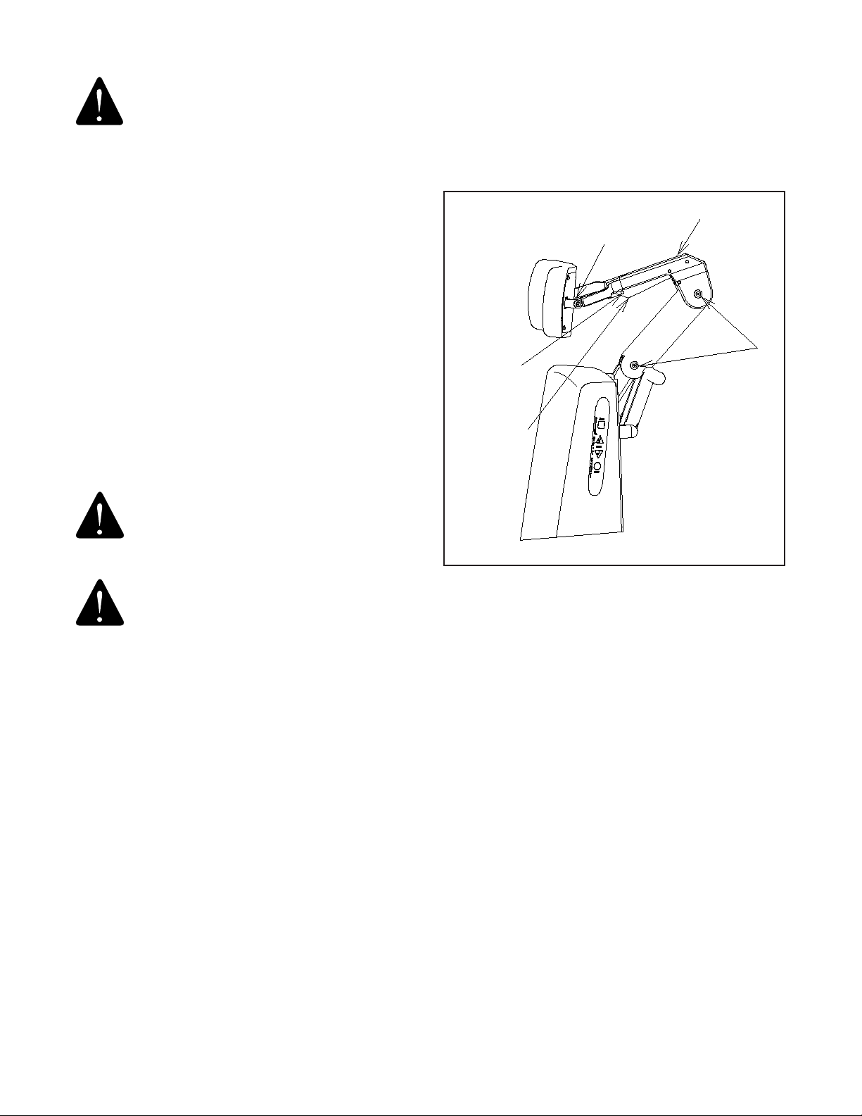
3.3. Chair Top
3.3.1. Positioning The Chair Back
• The chair back may be reclined or raised by either
pushing downward or pulling upward on the release lever
(Figure 4)
• If the chair is equipped with an articulating leg rest, the
foot-step and apron will rise when the back is reclined
• In the extreme reclined position these surfaces form a
flat table.
.
.
IN-62008
Page 9

FIGURE 4
Release Lever.
RELEASE LEVER
CAUTION: This exam Chair is designed
for use in a specific position called the
Intended Use Position. Prior to reclining a
patient, ensure the Chair Back is aligned
with the Chair’s power receptacle and
that the Chair Swivel is locked. The safe
working load is reduced if the Chair is
swiveled away from this Intended Use
Position, and may result in insufficient
stability.
PRÉCAUTION : Cette chaise d’examen
est conçue pour utilisation dans une
position spécifique appelée la position
d’utilisation prévue. Avant d’incliner un
patient, assurez-vous que le dossier de
la chaise est aligné avec le réceptacle
d’alimentation de la chaise et que le pivot
de la chaise est verrouillé. La charge
de travail sécuritaire est réduite si la
chaise est tournée hors de sa position
d’utilisation prévue et cela pourrait causer
une stabilité insuffisante.
3.4. Revolving/Rotation
3.4.1. The chair upper structure may be revolved 350°,
with a built-in stop to prevent continuous rotation. The lock
for revolving is controlled by a hand lever with chrome plated
knob located below the seat at the center and on either
side. Push the lever backward to release the lock and pull
upward to apply the lock.
3.5. Arm Movement
3.5.1. The chair arms may be raised to provide better
access to the patient or to permit entrance to or exit from
the chair.
3.5.2. The movements of both arms are identical and
completely independent of each other.
3.5.3. To raise an arm, push rearward on the middle joint
of the arm support link while raising upward on the arm.
A stop limits upward motion of the arm to a point parallel
to the plane of the back. Lowering the arm automatically
locks it in place against vertical motion in either direction.
CAUTION: This exam Chair is designed
for use with a specific maximum patient
weight as a static (non-moving) load.
Sudden weight shifts or impact loads
can exceed the safe static load rating of
the Chair, and may result in insufficient
stability.
PRÉCAUTION : Cette chaise d’examen
est conçue pour utilisation avec un poids
de patient maximum spécifique comme
charge statique (sans mouvement). Les
déplacements de poids soudains ou les
charges dynamiques peuvent excéder
la norme de charge statique sécuritaire
de la chaise, ce qui pourrait causer une
stabilité insuffisante.
CAUTION: This exam Chair is designed
for use with a patient properly positioned
in the Chair. Prior to reclining the Chair,
ensure that the patient is seated in the
Chair and that the patient position does
not move to an extreme position either
toward the head of the Chair or toward
the foot of the Chair, since this may result
in insufficient stability.
IN-6200
9
Page 10
PRÉCAUTION : Cette chaise d’examen est
conçue pour utilisation avec un patient
correctement positionné dans la chaise.
Avant d’incliner la chaise, assurez-vous
que le patient est assis dans la chaise et
que la position du patient ne se déplace
pas vers une position extrême soit vers
la tête, soit vers le pied de la chaise,
puisque cela pourrait causer une stabilité
insuffisante
3.6. Footrest
with a 3/32” hexagon key wrench. Next, tighten the pivot
screw on the other side of the pivot, with a 1/8” hexagon
key wrench. Now, retighten the set screw to retain the
pivot screw at the new adjustment. Either pivot may be
adjusted.
2
ACORN NUTS
3.6.1. The footrest may be retracted by lifting near its
outer edge. When fully retracted the footstep will stay in
place.
3.7. Headrest
3.7.1. The No. 18 headrest is the standard headrest for
the Model 6200 Chair.
WARNING- IF THE NO. 18 HEADREST
RECEIVES A IMPACT OR STRIKES AN OBJECT
WITH FORCE CONTACT RELIANCE® TECH
SERVICE IMMEDIATELY.
AVERTISSEMENT : SI L’APPUIE-TÊTE
# 18 REÇOIT UN CHOC OU FRAPPE
UN OBJET AVEC FORCE, CONTACTEZ
IMMÉDIATEMENT LE SERVICE TECHNIQUE
RELIANCE®.
3.7.2. Operation-No. 18, 22 Headrest
3.7.2.1. The No. 18, 22 headrest is designed so it can be
operated with just one hand. To unlock, squeeze the clear
plastic actuator into lock housing. This will allow both pivots
of the articulating arm to rotate so the headrest can be
moved to a new desired position. Once in the new position,
release the actuator. Make sure the actuator expands to its
original position fully exposing black dot on handle to insure a
positive lock. The headrest pad is free to rotate at all times.
(See Figure 5).3.7.3.
1
BLACK DOT
ACTUATOR
FIGURE 5
No. 18, 22 Headrest
3.7.3.2. The third adjustment is for proper clearance of the
block dot to indicate that the headrest is properly locked.
If the dot does not fully clear the lock housing when the
headrest is locked securely, turn the set screw located at the
top of the lock housing (Figure 5, item 2) counterclockwise
until the dot on the actuator is fully exposed.
3.7.4. Operation-No. 10 Headrest
3.7.4.1. The No. 10 headrest has a fixed, rigid upholstered
backboard which supports a sliding, center pillow section.
For patient comfort simply move this pillow to a desired
position.
Adjustment-No. 18, 22 Headrest
3.7.3.1. There are three adjustments provided on the No.
18, 22 headrest. The first is the tension on the pad rotation.
By tightening the two hex acorn nuts on the pad pivots with
a 3/8” open end wrench, the tension will be increased. To
adjust the drag on the pivots of the articulating arm, loosen
the set screw in the center of the pivot (Figure 5, item 1)
3.7.5. Operation-No. 11, 21 Headrest
3.7.5.1. A single handle on the rear of the No. 11, 21
headrests controls the locking mechanism. To unlock,
grasp the handle and turn counter-clockwise. Change the
tilt of the headrest until it is in the desired position. To lock,
turn the handle clock-wise until snug. (See Figure 6, No. 11
Headrest shown)
IN-620010
Page 11
3.7.6. Adjustment-No. 11, 21 Headrest
3.7.6.1. The handle on the outermost knob can be adjusted
to any preferred, locked position. Simply push in on the large
screw while pulling out on the handle. Rotate as desired, and
release. (See Figure 6, No. 11 Headrest shown)
3.7.6.2. The No. 21 headrest pillow assembly will slide
to a preferred patient position. Simply slide pillow on the
attached headrest strap to the desired position. (Not Shown)
CAUTION: Replace fuse(s) as marked. All
fuses must be replaced with a fuse of the same
size and rating. Refer to the Wire Diagrams
at the end of this Manual.
PRÉCAUTION : Remplacez le(s) fusible(s)
comme indiqué. Tous les fusibles doivent
être remplacés par un fusible de la même
dimension et de la même valeur. Se référer
aux schémas de câblage à la fin de ce manuel
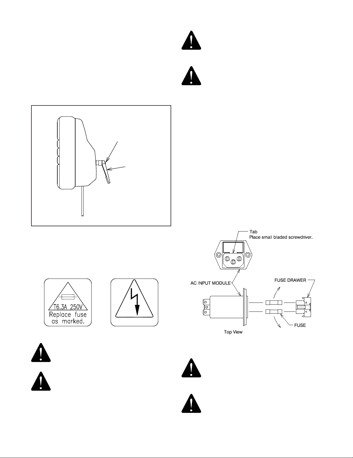
The chair contains two fuses located inside the AC Input
Module in the Base Assembly.
SCREW
HANDLE
FIGURE 6
No. 11 Headrest
4.0 LOCATING AND REPLACING FUSES
4.1. Fuse Replacement (AC Input Module)
4.1.1. Unplug the power cord from the AC power input
module. Referring to Figure 7, locate tab. With a tool similar
to a small common screwdriver placed under tab, pry fuse
drawer out. Remove the drawer by pulling it out with your
fingers.
4.1.2. To remove fuses from fuse drawer, tilt fuses in direction
of arrows as shown in Figure 7. Examine the fuses, replace
as necessary.
WARNING: DISCONNECT EQUIPMENT FROM
MAIN INPUT POWER BEFORE PROCEEDING WITH
ELECTRICAL INSPECTIONS OR MAINTENANCE.
AV ERT ISS EME N T : D ÉCONN EC TE Z
L’É QUI PEM EN T D E L’ A LI MEN TATI ON
ÉLECTRI QU E P RI NCIPAL E AVANT DE
PROCÉDER À DES INSPECTIONS ÉLECTRIQUES
OU À DE L’ENTRETIEN.
IN-6200
FIGURE 7
AC INPUT MODULE
CAUTION: To avoid a bind of the Fuse Drawer
within the AC Input Module, never install the
Fuse Drawer into the AC Input Module without
fuses.
PRÉCAUTION : Pour éviter que le tiroir à
fusible reste bloqué dans le module d’entrée
CA, n’installez jamais le tiroir à fusible
à l’intérieur du module d’entrée CA sans
fusibles.
11
Page 12

TROUBLESHOOTING GUIDE
PROBLEM PROBLEM CAUSE SOLUTION
CHAIR WILL NOT OPERATE. 1) POWER CORD NOT PLUGGED IN.
2) NO AC POWER AT WALL RECEPTACLE.
3) BLOWN LINE FUSE.
1) CHECK ALL WIRING CONNECTIONS.
2) RESTORE OUTLET POWER.
3) REPLACE FUSE.
OUTLET POWER OK, BUT NO
BEEP IS HEARD WHEN POWER
IS APPLIED.
1) BLOWN LINE FUSE.
2) LOOSE WIRING IN BASE.
3) OTHER.
1) REPLACE FUSE.
2) CHECK ALL WIRING CONNECTIONS.
3) CONTACT FACTORY
FOOTSWITCH FUNCTIONS NOT
OPERATING.
1) FOOTSWITCH CORD NOT CONNECTED. 1) CHECK ALL INTERNAL AND
EXTERNAL FOOTSWITCH WIRING
BACKSWITCH FUNCTIONS NOT
OPERATING.
1) DAMAGED OR DISCONNECTED WIRES
IN CHAIR BACK, UNDER CHAIR SEAT,
OR IN CHAIR BASE
1) CHECK ALL WIRING CONNECTIONS.
CHAIR BASE WILL NOT STAY UP 1) SOLENOID VALVE NOT CLOSED.
(DIRT IN VALVE.)
2) CONSTANT POWER APPLIED TO
SOLENOID.
3) OTHER
1) REPAIR OR REPLACE SOLENOID
VALVE.
2) CHECK FOR SWITCHES STUCK
"CLOSED" .
3) CONTACT FACTORY.
CHAIR BASE WILL NOT LOWER. 1) NO POWER TO PUMP MOTOR ASS'Y.
2) SOLENOID COIL BURNED-OUT
3) OTHER
1) CHECK FOR VOLTAGE.
2) REPLACE SOLENOID COIL.
3) CONTACT FACTORY.
CHAIR BASE WILL NOT RAISE.
PUMP MOTOR DOES NOT RUN.
1) NO POWER TO PUMP MOTOR ASS'Y
2) UP-LIMIT SWITCH STUCK "OPEN".
3) PUMP MOTOR BURNED-OUT.
4) OTHER
1) CHECK FOR VOLTAGE.
2) RE-ADJUST OR REPLACE SWITCH.
3) REPLACE PUMP MOTOR ASS'Y.
4) CONTACT FACTORY.
CHAIR BASE WILL NOT RAISE.
PUMP MOTOR RUNS.
1) SOLENOID VALVE NOT CLOSED.
(DIRT IN VALVE.)
2) CONSTANT POWER APPLIED TO
SOLENOID.
3) OTHER.
1) REPAIR OR REPLACE SOLENOID
VALVE.
2) CHECK FOR SWITCHES STUCK
"CLOSED".
3) CONTACT FACTORY.
BASE "STUTTERS" DURING
ASCENT.
1) HYDRAULIC FLUID LEVEL IS LOW. 1) CONTACT DEALER OR FACTORY
FOR INFORMATION ON ADDING OIL.
CHAIR BASE WILL NOT RAISE
OR LOWER FROM FLOOR UNIT.
1) CHAIR CONTROL CABLE NOT PLUGGED
IN.
2) BLOWN FUSE IN CHAIR BASE.
1) CHECK CABLE CONNECTIONS AT
STAND CHAIR
2) REPLACE FUSE.
CHAIR TOP "WOBBLES" ON
CHAIR BASE
1) LOCK NUT IS LOOSE.
(UNDER SEAT BOARD.)
1) TIGHTEN LOCK NUT.
CHAIR BACK RECLINES FULLY
WITHOUT HANDLE BEING
ACTIVATED.
1) BACK SPRING FAILURE 1) ADJUST GAS SPRING
2) REPLACE GAS SPRING
CHAIR BACK SPONGY WHEN
PATIENT PUTS PRESSURE ON
CHAIR BACK.
1) BACK SPRING FAILURE 1) REPLACE GAS SPRING
IN-620012
Page 13

CLEANING AND MAINTENANCE
Cleaning the Upholstery
When cleaning upholstery, it is suggested that you use all
recommended commercial cleaning agents in an inconspicuous spot to check for potential damage to the upholstery
material before applying to the entire area to be cleaned.
Day to Day soil:
Remove ordinary dirt and smudges with a mild soap and
warm water solution. Dry with a soft, lint-free cloth or towel.
For more difficult stains, use of a stronger detergent is
recommended; however, follow the detergent manufacturer’s
instructions closely.
Disinfecting Material:
In order to disinfect, use a 1:9 solution of bleach and water (1
part bleach to 9 parts water). Wipe surface with damp cloth
then rinse with water immediately, using a damp cloth.
Special cleaning problems:
The following methods are recommended to clean stains
on PreFixx-protected vinyl upholstery. Most stains will be
removed when these cleaning agents are used in the following order.
Type 1 Cleaners: Nonabrasive household cleaners to be
used with water and a soft cloth.
• Formula 409~ All-Purpose Spray Cleaner
• Fantastik® Spray Cleaner
PRÉ C AUTI O N : C e s s olv an t s s ont
extrêmement inflammables. Faites très
attention lors du nettoyage et avisez le
personnel dans la zone de tout danger.
Portez des gants de caoutchouc durant toute
activité de nettoyage. Faites attention en
nettoyant autour des boutons, des coutures
et autres finitions de bois ou décoratives,
puisque ces solvants pourraient endommager
sérieusement ces endroits.
Cleaning Painted Surfaces
The painted metal surfaces are covered in durable, powdercoated paint which is resistant to scratching and scuffing.
It may be cleaned with a clean cloth dampened with mild,
soapy water or equivalent household product that uses spray
application.
Recommended Infection Control Products
The disinfectant/cleaner products that we have tested and
recommend for our upholstery, painted items and plastic
covers are as follows.
• Cavicide® Hospital Disinfectant
• Precise® Hospital Foam Cleaner Disinfectant
• Other similar household cleaners and bleaches
Type 2 Cleaners: Solvent-type cleaner to be liberally
applied with a soft cloth. Dry area with another cloth, rinse
with clean water and dry.
• Rubbing alcohol (isopropyl alcohol)
• Lighter fluid (naptha)
Type 3 Cleaners: Strong, active solvent cleaners such as
nail polish remover (acetone/water) to be applied with a soft
cloth. Stain should be removed with less than six (6) rubs; if
stain persists after six rubs, contact manufacturer. Dry area
with another cloth, rinse with clean water and dry.
CAUTION- These solvents are highly
flammable. Exercise proper care in cleaning
and notify personnel in area of danger. Wear
rubber gloves during all cleaning activity. Use
caution in cleaning around buttons, stitching
and wooden or other decorative trim, since
these solvents could seriously damage such
areas.
CAUTION : Follow manufacturer’s directions for
concentration and application of disinfecting
cleaner. Avoid prolonged application of any
disinfectant/cleaner products, because
they may cause staining or discoloration of
material.
PRÉCAUTION : Suivez les instructions
du fabricant pour la concentration et
l’application de nettoyeurs désinfectants.
Évitez une application prolongée de tout
produit désinfectant/nettoyant, parce que
ceux-ci pourraient causer des taches ou une
décoloration du matériel.
WARNING: REFER TO LOCAL OR
HEALTHCARE PROFESSION GUIDELINES
FOR SELECTING EFFECTIVE INFECTION
CONTROL PRODUCTS.
AV E R T ISSEM E N T : SE RÉ F ÉRER
AUX DIRECTIVES LOCALES OU DES
PROFESSIONS DE LA SANTÉ POUR
SÉLECTIONNER DES PRODUITS DE
CONTRÔLE D’INFECTION EFFICACES.
IN-6200
13
Page 14

PARTS LIST
RELIANCE® MODEL 6200
EXAMINATION AND TREATMENT CHAIR
Note: When ordering parts, please:
1. Advise dealer or factory of model and serial number of unit. These numbers are on the
plate that is located at rear, near bottom, of chair back.
2. Specify color of painted parts. Painted parts have an asterisk(*) behind the part description.
Note : Quand pièces de commande, s’il vous plaît :
1. Informez le distributeur ou l’usine du modèle et du numéro de série de l’ensemble. Ces
numéros sont de la plaque qui est située à l’arrière, près du bas, de l’arriére de présidence.
2. Indiquez la couleur des pièces peintes. Les pièces peintes ont un astérisque (*) derrière la
description de pièce.
Should your chair not perform properly, or if replacement parts are
needed, contact the Reliance® Distributor, where you purchased this
product or contact the Technical Service Department, Reliance® Medical
Products, Inc., 3535 Kings Mills Road, Mason, Ohio 45040-2303, or call
(800) 735-0358.
IN-620014
Page 15

ITEM PART NO. DESCRIPTION ITEM
PART NO. DESCRIPTION
1 Chair Top Assembly* (See Figure 8) 7 1479473 Upholstered Apron Assembly**
2 Base Assembly* (See Figure 9) 8 1467673 Upholstered Arm Assembly-Right**
3 Headrest Assemblies (See Figures 11 thru 14) 9 1467773 Upholstered Arm Assembly-Left**
4 1760403 Footstep* 10 0667873 Upholstered Arm Pad Assembly**
5 1715073 Upholstered Back Assembly** 11 1765073 Scuff Pad**
6 1479373 Upholstered Seat Assembly** 12
M
ODEL AND SERIAL
N
UMBER PLATE
FIGURE 7
6200 CHAIR ASSEMBLY
5
8, 9
10
6
2
7
4
11
** Please specify upholstery color when ordering.
To order complete Upholstery Set use P/N.
2727873 Designer Upholstery Set With No. 18 Headrest Pad - 6200
*Please specify paint color when ordering.
IN-6200
15
Page 16

47
FIGURE 8
6200 CHAIR ASSEMBLY
46
(2)
32
31
27
(2)
30
33
58
38
28
39
83
58
24
77
56
40
20
(2)
23
34
43
41, 42
45
50
45
72
51
49
82
53
70
6,58
68
7
(4)
52
69
5
8
9, 10
71
12
11
66
84
71
14
75
44
13, 22
76
(4)
17
15
16
1
48
29
81
22
79, 80
19
18
57
68
65
64
21
78
3
2
69
55, 59
26
25
69, 73, 74
35
60
37
(2)
54
36
61, 62, 63
IN-620016
Page 17

ITEM
PART NO. DESC RIPTION ITEM
PART NO. DESCRIPTION
1546699 Hinge Cable Assembly 23
1
1472195 Gas Spring Pivot Block 24
2
0978499 5/8 Dia. Steel Ball 25
3
4
1471995 Gas Spring Rease Actuator 27
5
1509199 Pivot Block Pin 28
6
1475685 Back Plate Weldment 29
7
1604095 Gas Spring Release Pivot 30
8
1477503 Side Plate Assembly - Right* 31
9
1477603 Side Plate Assembly - Left* 32
10
0396299 Spring Washer 33
11
0725999 S.H.S.S. 1/4-20 x 3/4 34
12
0761899 3/16 x 1 Roll Pin 35
13
0556285 Armrest Cover 36
14
0136703 Headrest Bracket* 37
15
1573503 Gas Spring Release Bar* 38
16
26
0729699
1472795
0722899
1760403
0609699
1471882
1734099
0614299
0606099
0605999
1473803
1473903
0605299
0605399
0569499
1473203
1/2 Washer
Apron Tie Bar
S.S.H.S. 1/4-20 x 3/8
Footrest*
Fiber Washer
Footrest Link
Snap Bushing
Footstep Pin Assembly
9/32 Dia Steel Ball
Spring
Apron Bracket - Right*
Apron Bracket - Left*
Lock Handle Assembly - Right
Lock Handle Assembly - Left
Roll Pin 3/16 x 3/4
Apron Control Link*
1473472 Back Cover - With ENT* 39
17
1472672 Back Cover - Without ENT* 40
0605499 Lock Shaft 41
18
0411199 Fiber Washer 42
19
0603803 Back Hinge Assembly - Right* 43
20
0603903 Back Hinge Assembly - Left* 44
21
22 0732699
1/2 Retaining Ring 45
For Items 46 thru 84 see page 18.
0401299
1472203
1842692
1842792
0122203
0122303
0563299
3/8 x 1 Shoulder Bolt
Apron Control Arm*
Armrest Link Assembly - Right
Armrest Link Assembly - Left
Armrest Bracket - Right*
Armrest Bracket - Left*
Linkage Pin
*Please specify paint color when ordering.
IN-6200
17
Page 18

ITEM PART NO.
DESC RIPTION
ITEM PART NO.
DESC RIPTION
46 2027099 Membrane Switch Assembly 66 0706399 H.H.C.S. 1/4-20 x 1 1/2
47 1546299 Ribbon Cable 67 0527899 1/4-20 Flex Lock Nut
48 0387303 Plug Button* 68 0758599 R.H.M.S. #10-24 x 5/8
49 0603399 Truarc Ring 69 0703299 #10-24 Hex Nut
50 1472999 10mm x 30mm Shoulder Bolt 70 0569699 O.H.W.S. #6 x 3/4 Phil
51 0307999 H.H.C.S. 5/16-18 x 3/4 71 0808699 F.H.C.S. 1/4-20 x 1 Sck't
52 0643599 Lock Plug 72 0929199 F.H.M.S. #10-24 x 3/4 Phil
53 0722899 S.H.S.S. 1/4-20 x 3/8 73 0728199 #10 Split Lock Washer
54 0561799 Locking Cam 74 0729999 1/4 Washer
55 1036799 H.H.C.S. 5/16-18 x 5/8 75 0704099 1/4-20 Hex Nut
56 1504185 Seat Plate Weldment 76 0716499 T.H.M.S. #10-24 x 3/8
57 2014399 Gas Spring 77 0704899 5/16-18 Hex Nut
58 0732599 Truarc Ring 78 0713599 F.H.M.S. 1/4-20 x 1.25 Phil
59 0728399 5/16 Washer 79 0729199 1/4 Lock Washer
60 1964085 Seat Support 80 0703699 1/4-20 Keps Nut
61 0708599 H.H.C.S. 3/8-16 x 1 1/2 81 1475399 M8 x 1.25 Hex Nut
62 0728499 3/8 Lock Washer 82 1660799 4 Circuit Cap
63 0705199 3/8-16 Nut 83 1660899 6 Circuit Cap
64 1586899 6 in Extention Spring 84 0299899 F.H.M.S. 1/4-20 x 2 1/2 Phil
65 1655599 6 1/2 in Flexible Tubing 85
*Please specify paint color when ordering.
Part List for Figure 8 page 16
IN-620018
Page 19

(NOTES)
IN-6200
19
Page 20

FIGURE 9
6200 BASE ASSEMBLY
20
33
18
9
21
34
35
3, 4
11
10
19
7
25
26
8
15
24
36
29
12
32
27
22
30, 17
31
23
5
38
30, 17
6
13
16, 17
37, 36
39
14
36
1
2
IN-620020
Page 21

ITEM
PART NO.
DESCRIPTION
ITEM PART NO.
DESCRIPTION
1
2081203 Base
20
0560099 Thrust Washer
2
2065599 Base Cover
21
0123885 Lock Nut
3
2065199 Base Housing - Low - RH
22
1548195 Wiring Tube-High
2065399 Base Housing - High - RH 1548395 Wiring Tube-Low
4
2065299 Base Housing - Low - LH
23
1127599 Union Tee
2065499 Base Housing - High - LH 24 1659299 Power Cord Assembly
5
Lift Assembly (See Figure 10) 25 1550599 Chair Control Cable-LV To LV
6
1707792 Solenoid Valve Assembly-120V
26
1608292 Footswitch Assembly
1707892 Solenoid Valve Assembly-230V
27
1634299 Fuse, 6.3 A / 250V-120V
7
1702892 Keyshield Assembly-Low* 1634999 Fuse, 4 A / 250V-230V
1702992 Keyshield Assembly-High*
28
1976799 Power Entry Module W/ Filter
8
2720092 Pump/Motor Assembly-120V 29 Fusedrawer, 2 Pole (In Item 28)
2720192 Pump/Motor Assembly-230V 30 0458999 Tubing-5 in
9
1547899 Piston Rod Bolt
31
1597299 Capacitor, Starting-120V
10
1525899 Set Screw-#10-24 x 1/4 2002199 Capacitor, Starting-230V
11
0607299 Washer
32
1993592 Ent Transformer Assembly - 120V
12
2721092 Hose Assembly 1994392 Ent Transformer Assembly - 230V
13
1596292 Pressure Tube Assembly
33
2722099 Base Cable Grey
14
2025599 P.C. Board Assembly 34 1643899 6 Circuit Plug
15
2720892 AC Input Assembly
35
1643799 4 Circuit Plug
16
0458999 Tubing-5-1/2 in
36
1720399 PH Phil w/Lock Washer-#10-24 x 1/2
17
1081999 Tubing Insert
37
2081099 Housing Mount Bracket
18
1547999 Snap Bushing
38
0708599 HHCS 3/8-16 x 1.5
19
0559999 Thrust Bearing
39
1569999 Circuit Board Support
To order complete Base Assembly use P/N’s.
2716292 Chair Base Assembly - Low - 120V*
2716392 Chair Base Assembly - High - 120V*
2716492 Chair Base Assembly - Low - 230V*
2716592 Chair Base Assembly - High - 230V*
*Please specify paint color when ordering.
NOTE- Power cord for 230V base does not
include a plug.
NOTE- Le cordon de secteur pour la base
230V ne comprend pas une fiche.
IN-6200
21
Page 22

1
2
10
9
3
4
6
5
7
8
11
41
38
26
42
40
43
20
30
31
32
33 & 37
34
27
28
29
35
36
12
13
15
16
19
18
14
17
25
24
23
22
21
18
39
FIGURE 10
LIFT ASSEMBLY
IN-620022
Page 23

ITEM
PART NO.
DESCRIPTION
ITEM
PART NO.
DESCRIPTION
1 1012795 Lift Base 22 0733299 Retaining Ring
2 1019095 Lift Top 23 0512599 Backup Ring
3 0439979 Switch Plate 24 0730899 U - Pack
4 0929699 Insulator 25 0512499 Piston Ring
5 1011399 Switch 26 0353199 Cylinder Gasket
6 0727599 Drive Screw 27 0569299 Pin - Roll
7 0731499 "O" Ring 28 0466399 Filter Screen
8 1454699 Pin 29 0446099 Snap Ring
9 0485199 Nut - Acorn 5/16 30 0741799 Valve Ball
10 0365799 Gasket - Tie Rod 31 0731199 "O" Ring
11 0432599 Base Column Seal 32 0441999 Valve Seat
12
0903292 Cylinder Assembly - High 33 1012499 Valve Housing
0526792 Cylinder Assembly - Low 34 0363299 Relief Valve Plunger
13 Spacer - Cylinder (in Item 12) 35 0784699 Relief Valve Spring
14 Bushing (in Item 12) 36 1012399 Set Screw
15 Ring - Quad (in Item 12) 37 0731299 "O" Ring
16
0902285 Base Column - High 38 0442499 Valve Spring
0563885 Base Column - Low 39 2720799 Elbow - 45°
17 0432599 Base Column Seal 40 1081899 Elbow - 90°
18
0901999 Tie Rod - High 41 0447199 Elbow - 90°
0563699 Tie Rod - Low 42 0303699 Plug - Pipe 1/8-27 Sckt Head
19 Pin - Roll (in Item 12) 43 1060392 Tubing Assembly
20 0422899 Disc - Valve
21
1183592 Piston Rod - High
1183692 Piston Rod - Low
To order complete Lift Assembly use P/N’s.
2721192 Lift Assembly - Low
2721292 Lift Assembly - High
IN-6200 23
Page 24

FIGURE 11
# 18 & # 22 HEADREST ASSEMBLY
16
1
11
8
5
9
2
6
7
9
3
18
17
14
15
4
13
12
10
IN-620024
Page 25

ITEM PART NO. DESCRIPTION
1
0475673 Pad Assembly - No. 18*
1680073 Pad Assembly - No. 22*
2 1460492 Yoke Assembly*
3 1460592 Gear & Bracket Assembly*
4 1470692 Actuator & Lock Gear Assembly
5 1425299 Pivot Cap, Right
6 1425399 Pivot Cap, Left
7 0307599 Screw, Shoulder 1/4 x 1
8 0726099 S.H.S.S. #10-24 x 3/16
9 1424999 Washer, 2" OD
10 1454799 B.H.C.S. 1/4-28 x 1/2
11 1456399 S.H.S.S. #10-24 x 3/8
12 1427099 Spring Plunger
13 1538899 Spring
14 1454999 L.H.C.S. #10-24 x 3/4 - Socket
15 1434799 Pivot Cap, Pad
16 0467195 Bushing .188 I.D x .312 O.D.
17 1456199 Nut, Acorn 1/4-20 Low Crown
18 1425699 Screw, Shoulder .25 x .50
To order complete Headrest Assembly use P/N. To order complete Screw Assembly use P/N.
144080 #18 Headrest Assembly* 2721692 Middle Joint Screw Assembly
144070 #22 Headrest Assembly* Includes: Item’s 5, 6, 7 & 8.
*Please specify paint color when ordering. 2721792 Bottom Joint Screw Assembly
** Please specify upholstery color when ordering.
Includes: Item’s 5, 6, 8 & 18
IN-6200
25
Page 26

FIGURE 12
# 10 HEADREST ASSEMBLY
3
1
4
2
7
9
6
(4)
11
(4)
12
8
10
5
(4)
IN-620026
Page 27

ITEM PART NO. DESCRIPTION
1
0665073 Uph # 10 Board Assembly**
2 0574173 Pillow Assembly - #10**
3 0567903 High Back Cover*
4 0568003 Pillow Back Cover*
5 0845199 F.H.W.S. #6 x .50 - Phil
6 0569699 O.H.W.S. #6 x 3/4
7 0569799 #6 Finishing Washer
8 0557499 Mounting Plate Assembly
9 0123203 Bracket Cover*
10 0808699 F.H.C.S 1/4-20 x 1.00 - Socket
11 0788699 S.H.C.S. 1/4-20 x 1.00
12 1454799 B.H.C.S. 1/4-28 x 1/2
To order complete Headrest Assembly use P/N.
665200 #10 Headrest Assembly*
*Please specify paint color when ordering.
** Please specify upholstery color when ordering.
IN-6200
27
Page 28

13
11
FIGURE 13
# 11 HEADREST ASSEMBLY
2
12
(4)
18
16, 17
(4)
4
14
1
7
3
8
10, 17
9
15
5
6
IN-620028
Page 29

ITEM PART N O. DESCRIPTION
1
1557573 Uph # 11 Pad Assembly**
2 1558897 Headrest Cover
3 1562499 3/8" Adjustable Handle
4 1558903 Mounting Plate*
5 1559295 Headrest Lock Block
6 1559395 Headrest Pad Mounting Plate
7 1207199 3/4 O.D x 3/8 I.D x 3/4 Spacer
8 1562899 S.H.S.S. 3/8-16 x 2 1/2
9 0472999 Retaining Ring
10 1559599 R.H.M.S 1/4-20 x 2 1/2
11 1523699 T.H.M.S. 5/16-18 x 3/8
12 1571799 Short Standoff
13 1559092 Stud Mount Assembly
14 0712999 F.H.M.S
1/4-20 x 3/4
15 1559499 F.H.M.S 3/8-16 x 3/4
16 0713199 R.H.M.S 1/4-20 x 3/4
17 0728299 1/4 Lockwasher
18 1454799 B.H.C.S., 1/4-28 x 1/2
To order complete Headrest Assembly use P/N.
155720 #11 Headrest Assembly*
*Please specify paint color when ordering.
** Please specify upholstery color when ordering.
IN-6200
29
Page 30

FIGURE 14
11
# 21 HEADREST ASSEMBLY
2
12
(4)
13
21
16, 20
(4)
5
14
(2)
1
3
4
19
(4)
15
17
6
18
10, 20
9
8
7
IN-620030
Page 31

ITEM PART NO. DESCRIPTION
1
1846373 Uph # 21 Pad Assembly**
2 1558897 Headrest Cover
3 0574173 Pillow Assembly**
4 0568003 Pillow Board Back Cover*
5 1558903 Mounting Plate*
6 1562499 3/8" Adjustable Handle
7 1559395 Headrest Pad Mounting Plate
8 1559295 Headrest Lock Block
9 0472999 Retaining Ring
10 1559599 R.H.M.S 1/4-20 x 2 1/2
11 1523699 T.H.M.S. 5/16-18 x 1/2
12 1571799 Short Standoff
13 1559092 Stud Mount Assembly
14 0712999 F.H.M.S 1/4-20 x 3/4
15 1559499 F.H.M.S 3/8-16 x 3/4
16 0713199 R.H.M.S 1/4-20 x 3/4
17 1207199 3/4 O.D x 3/8 I.D x 3/4 Spacer
18 1562899 S.H.S.S. 3/8-16 x 2 1/2
19 0845199 F.H.W.S. #6 x 1/2 - Phil
20 0728299 1/4 Lockwasher
21 1454799 B.H.C.S., 1/4-28 x 1/2
To order complete Headrest Assembly use P/N.
184640 #21 Headrest Assembly*
*Please specify paint color when ordering.
** Please specify upholstery color when ordering.
IN-6200
31
Page 32

FIGURE 15
WIRING DIAGRAM
LED 1
3
4
2 1
AUTO
PART # 1546299
RIBBON CABLE
LED 2
3
4
2 1
BASE
RAISE
LOWER
OUTPUT
1
1
LED 3
3
4
12
BASE
STOP
PART NO. - 2027099
MEMBRANE SWITCH
INPUT
1
GYO
R
BL V
GSH
W
B
Y
1
1546699
HINGE CABLE ASSY
W/B
BR
V
1
W/B
BR
B
G
W
R
BL
O
SH
1
G/B
1
B
R/B
W/B
BL
R
W
SH G
1
O
STRIPE TO PIN-1 BOTH ENDS
1
OUTPUT
1
AUTO
BASE
RAISE
14 2
3
LED 1
LED 2
STOP
BASE
LOWER
214
14 2
3
3
INPUT
1
LED 3
TO ENT LIGHT
(P/N 1736992)
PART NO. - 2027099
MEMBRANE SWITCH
IN-620032
Page 33

230V - 2720192
120V - 2720092
PUMP MOTOR ASSY.
PUMP
MOTOR
120V - 1707792
230V - 1707892
SOLENOID ASSY.
B
W
B
230V - 1994392
120V - 1993592
R
W
Y
B
CAPACITOR
230V - 2002199
120V - 1597299
COLOR
BLACK
BLUE
WIRE COLOR
BL
B
ABBREVIATIONS
ABBR
ORANGE
BROWN
GREEN
GRAY
BR
GYGOVR
WHITEW
VIOLET
RED
Y YELLOW
ENT TRANSFORMER ASSY (OPT)
Y
Y
Y
1
1
1
2722099
BASE CABLE
B
W/B
R/B
R
BL
O
G/B
W
G
SH
1
1
TIMER
CIRCUIT BOARD
2025599 - 120V & 230V
1
1
1
ENT
SOL
1
1
RELAY
DRIVER
1
1
POWER
SUPPLY
1
BUFFER
OPTICAL
W
PUMP
LIMIT
ENT IN
AC IN
FOOT
CONSOLE
1038992
LIMIT SWITCH
B
B
1
B
W
1
1
B
O
1
G
R/W
BL
W
R
1
O/B
G/B
R/B
B/W
CABLE ASSY, AC INPUT
1993392
G/Y
B
W
(1)BR
R
W
R/W
O
BBL
G
O/B
B/WG/B
R/B
(3)R
(4)G
(6)O
(7)BL
(5)W
(2)B
RECEPTACLE
CHAIR CONTROL
1607899
CABLE ASS'Y
LV FOOTSWITCH
LINE FUSES
B
W
O
BL
3
UP
6
G
11
4
AUTO
7
BR
DOWN
B
POWER ENTRY MODULE W/FILTER 1976799
230V-4.0A/250V - 1634999
120V-6.3A/250V - 1634299
L
N
CHAIR BASE
FOOTSWITCH ASS'Y - 1608292
POWER CORD ASSEMBLY 1659299
(OPTIONAL)
IN-6200
FOOT/CONSOLE CABLE-1993199
33
Page 34

(NOTES)
IN-620034
Page 35

LIMITED WARRANTY
The Reliance® product must be used only for the purposes and in the manner described in the literature
distributed with the product. The products are warranted against defective materials and workmanship for the
period set forth in the warranty provided with each product. Products or parts thereof will be repaired or replaced
as required at Reliance® Medical Products, Inc. Such repair or replacement shall be the sole remedy under
this warranty. This warranty extends only to the original purchaser from an authorized Reliance® dealer and is
subject to the following conditions:
1. The warranty card must be completed and returned to Reliance® Medical Products, Inc. within two(2)
weeks from the date of installation.
2. Installation and servicing of the products must be performed by trained Reliance® equipment dealer service
personnel in accordance with the appropriate instructions manual for the products.
3. The products have not sustained breakage or other type damage due to accident or misuse.
4. This warranty will not apply to Reliance® products which have had the serial number removed, altered or
effaced.
EXCEPT FOR THE EXPRESS WARRANTY SET FORTH ABOVE, RELIANCE® DOES NOT GRANT ANY
WARRANTIES, EITHER EXPRESS OR IMPLIED, INCLUDING IMPLIED WARRANTIES OF MERCHANTABILTY
OR FITNESS FOR A PARTICULAR USE.
Reliance® Medical Products neither assumes nor authorizes any person to assume for it, any other liability
in connection with the sale and use of its products.
REMEDIES ARE LIMITED EXCLUSIVELY TO REPAIR OR REPLACEMENT OF PARTS. RELIANCE®
MEDICAL PRODUCTS, INC. EXPRESSLY DISCLAIMS LIABILITY FOR INCIDENTAL OR CONSEQUENTIAL
DAMAGE RESULTING FROM THE USE OF THE EQUIPMENT.
Claims covered by this warranty will be honored when presented within one (1) month from discovery of a defect.
IN-6200
35
Page 36

MADE IN AMERICA
3535 Kings Mills Road
Mason, Ohio 45040-2303
1-800-735-0357(Customer Service)
1-800-735-0358 (Technical Service)
(513) 398-3937
Http://www.reliance-medical.com
P/N 27168 REV E
© Copyright 2006
Printed in U.S.A.
Revised 02-2012-7925
 Loading...