

Page 1
5120/5126 TOP SHOT
MANURE SPREADER
OPERATOR’S MANUAL
W ARNING
Revision #1
5120 Starting Serial #31 1175
5126 Starting Serial #312139
H&S MANUFACTURING CO.,INC.
P.O. BOX 768 (715) 387-3414 FAX (715) 384-5463
READ AND UNDERSTAND THIS MANUAL
BEFORE OPERATING THIS EQUIPMENT.
UNSAFE OPERATION OR MAINTENANCE OF
THIS EQUIPMENT CAN RESULT IN SERIOUS
INJURY OR DEATH.
HSMFG1212 Part #59622
Manufactured By
MARSHFIELD, WISCONSIN 54449
Page 2

CONTENTS
Warranty & W arranty Registration Card . . . . . . . . . . . . . . . . . . . . . . . . . . . . . . . . . . . . . . . . . . . . . . . 1-2
Manufacturers St atement . . . . . . . . . . . . . . . . . . . . . . . . . . . . . . . . . . . . . . . . . . . . . . . . . . . . . . . . . . . . 2
Dealer Pre-Delivery Checklist . . . . . . . . . . . . . . . . . . . . . . . . . . . . . . . . . . . . . . . . . . . . . . . . . . . . . . . . 3
Dealer Delivery Checklist . . . . . . . . . . . . . . . . . . . . . . . . . . . . . . . . . . . . . . . . . . . . . . . . . . . . . . . . . . . . 5
Safety Information - Be Alert Symbol . . . . . . . . . . . . . . . . . . . . . . . . . . . . . . . . . . . . . . . . . . . . . . . . . . . . 7
Safety Information - Explanation of Safety Signs . . . . . . . . . . . . . . . . . . . . . . . . . . . . . . . . . . . . . . . . . . 8
Safety Decals . . . . . . . . . . . . . . . . . . . . . . . . . . . . . . . . . . . . . . . . . . . . . . . . . . . . . . . . . . . . . . . . . . . 9-10
Safety Information - Warning - Owner Must Read and Understand . . . . . . . . . . . . . . . . . . . . . . . . . . . 1 1
Cap Screw Torque Values . . . . . . . . . . . . . . . . . . . . . . . . . . . . . . . . . . . . . . . . . . . . . . . . . . . . . . . . . . . . 12
Set-Up & Assembly . . . . . . . . . . . . . . . . . . . . . . . . . . . . . . . . . . . . . . . . . . . . . . . . . . . . . . . . . . . . . . . . 13
Transporting . . . . . . . . . . . . . . . . . . . . . . . . . . . . . . . . . . . . . . . . . . . . . . . . . . . . . . . . . . . . . . . . . . . . . . . 14
Storage . . . . . . . . . . . . . . . . . . . . . . . . . . . . . . . . . . . . . . . . . . . . . . . . . . . . . . . . . . . . . . . . . . . . . . . . . . . 14
Preparing for Operation . . . . . . . . . . . . . . . . . . . . . . . . . . . . . . . . . . . . . . . . . . . . . . . . . . . . . . . . . . 15-17
Operation . . . . . . . . . . . . . . . . . . . . . . . . . . . . . . . . . . . . . . . . . . . . . . . . . . . . . . . . . . . . . . . . . . . . . . 18-23
Adjustments . . . . . . . . . . . . . . . . . . . . . . . . . . . . . . . . . . . . . . . . . . . . . . . . . . . . . . . . . . . . . . . . . . . . 24-25
Service . . . . . . . . . . . . . . . . . . . . . . . . . . . . . . . . . . . . . . . . . . . . . . . . . . . . . . . . . . . . . . . . . . . . . . . 26-27
Optional Equipment . . . . . . . . . . . . . . . . . . . . . . . . . . . . . . . . . . . . . . . . . . . . . . . . . . . . . . . . . . . . . . . . . . 28
Lubrication Guide . . . . . . . . . . . . . . . . . . . . . . . . . . . . . . . . . . . . . . . . . . . . . . . . . . . . . . . . . . . . . . . 29-32
Decal Location . . . . . . . . . . . . . . . . . . . . . . . . . . . . . . . . . . . . . . . . . . . . . . . . . . . . . . . . . . . . . . . . . . 33-35
Troubleshooting Guide . . . . . . . . . . . . . . . . . . . . . . . . . . . . . . . . . . . . . . . . . . . . . . . . . . . . . . . . . . . . . . 36
Service Notes . . . . . . . . . . . . . . . . . . . . . . . . . . . . . . . . . . . . . . . . . . . . . . . . . . . . . . . . . . . . . . . . . . . . . . . 37
Specifications . . . . . . . . . . . . . . . . . . . . . . . . . . . . . . . . . . . . . . . . . . . . . . . . . . . . . . 40 & Inside Back Cover
Page 3
Page 4
Page 5

DEALER PRE-DELIVERY CHECK LIST
AFTER COMPLETION, DEALER SHOULD REMOVE AND RETAIN FOR RECORDS
After the Top Shot has been completely set-up, check to be certain it is in correct operating order
before delivering to the customer . The following is a list of point s to inspect. Check off each item as
you have made the proper adjustments and found the item operating satisfactorily.
Top Shot was not damaged in shipment. Check for dents and loose or missing parts.
Report damage immediately to H&S Manufacturing Co., Inc.
All bolts and fasteners are tight.
Top Shot has been correctly assembled according to instructions in this manual.
Wheel nuts and all other fasteners are tightly secured.
All grease fittings have been lubricated. Gearboxes are filled to proper levels if applicable.
Lubrication Chapter of this manual for details.
See
Hoses and fittings are properly attached and there are no visible leaks.
Guards and shields are secure.
Wheels are properly mounted.
Tires are inflated to correct pressure.
Chains tension is properly adjusted. See Adjustment Chapter of this manual.
Decals are in place and legible.
(Remove Dealer File Copy At Perforation)
PTO guard turns freely.
Discharge door operates smoothly.
Main Auger operates up and down smoothly.
Hydraulic system does not leak under pressure.
Lights and wiring functioning properly .
Electronic Scale (if provided) operates properly .
Implement and all components are functioning properly .
Connect the Top Shot onto a proper horsepower 540 RPM or 1000 RPM (if applicable)
tractor and attach the PTO. Connect the lights. Run the Top Shot and make sure all
components operate properly.
Inspection Date____________________ Model Number ________________________________
Serial Number______________________________________________
Dealer’s Name ________________________________________________________________
Signature of Pre-Delivery Inspector ________________________________________________
-3-
Page 6

Intentionally Left Blank
-4-
Page 7

DEALER DELIVERY CHECK LIST
AFTER COMPLETION, DEALER SHOULD REMOVE AND RETAIN FOR RECORDS
This check list that follows is an important reminder of valuable information that should be
passed on to the customer at the time this machine is delivered.
Check off each item as you explain it to the customer.
This delivery check list, when properly filled out and signed assures the customer that the
Pre-Delivery Service was satisfactorily performed.
(Remove Dealer File Copy At Perforation)
Explain to the customer that the Pre-Delivery Inspection was made.
Explain to the customer all the safety precautions they must exercise when operating this
unit.
Explain to customer that regular lubrication is required for proper operation and long life of
machine. Show customer the
Give the customer the Operator’s Manual and make sure they read and understand all
operating and service instructions.
Record model and serial number on this page and page 37 of this Operators Manual.
Have customer sign a completed “Warranty Registration,” and mail it promptly.
Lubrication Chapter of the Operator’s Manual.
Date Delivered __________________________________
Dealer’s Name ________________________________________________________________
By __________________________________________________________________________
Signature of Original Buyer ______________________________________________________
Note: Warranty is not valid until warranty card is completed and returned to H&S Mfg. Co., Inc.
-5-
Page 8

Intentionally Left Blank
-6-
Page 9

SAFETY INFORMATION
BE
YOUR SAFETY
ALERT!
THIS SYMBOL IS USED THROUGHOUT THIS BOOK WHENEVER YOUR PERSONAL SAFETY
IS INVOLVED. TAKE TIME TO BE CAREFUL. REMEMBER: THE CAREFUL OPERATOR IS
THE BEST OPERATOR. MOST ACCIDENTS ARE CAUSED BY HUMAN ERROR.
CERTAIN PRECAUTIONS MUST BE OBSERVED TO PREVENT THE POSSIBILITY OF INJURY
OR DAMAGE.
H&S MANUF ACTURING CO., INC.
IS INVOL VED.
-7-
Page 10
SAFETY INFORMATION
Keep signs in good condition. Immediately replace any missing or damaged signs.
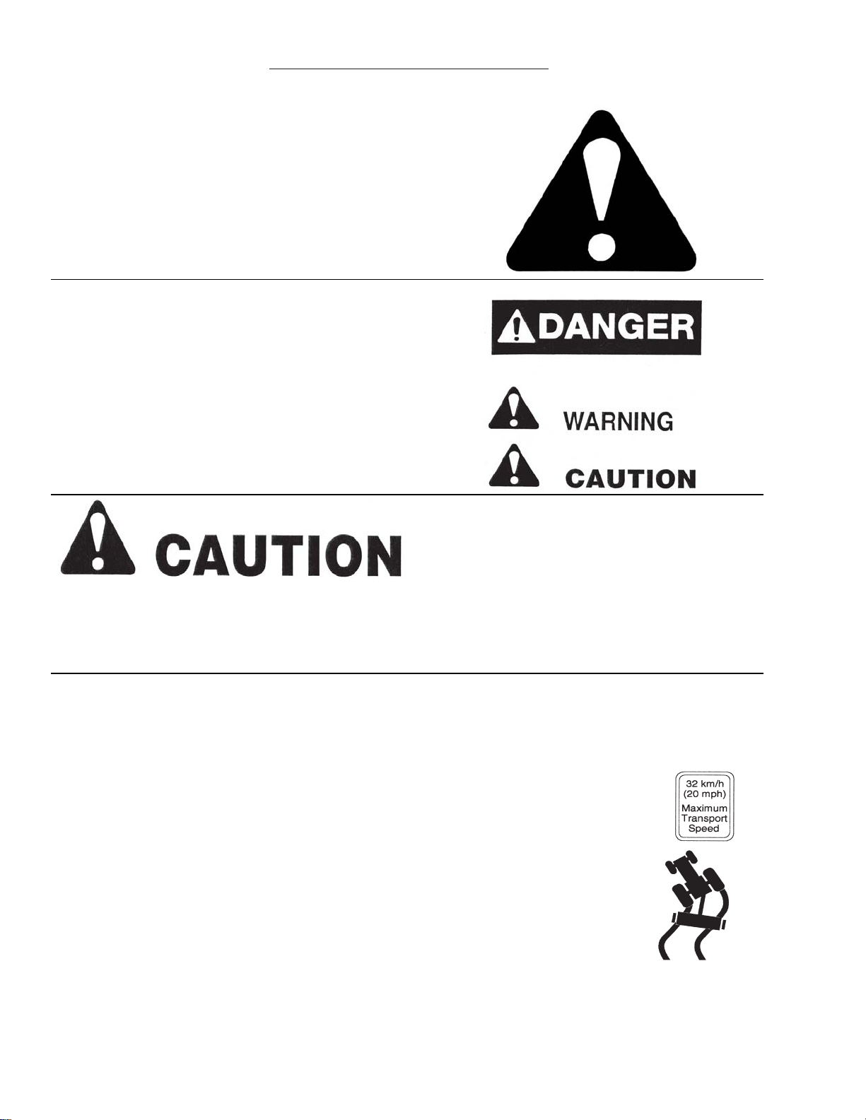
RECOGNIZE SAFETY INFORMATION
This is the safety-alert symbol. When you see this symbol
on your machine or in this manual, be alert to the potential
for personal injury .
Follow recommended precautions and safe operating
practices.
UNDERSTAND SIGNAL WORDS
A single word; DANGER, WARNING, or CAUTION is used
with the safety-alert symbol. DANGER identifies the most
serious hazards.
Safety signs with signal word DANGER or WARNING are
typically near specific hazards.
General precautions are listed on CAUTION safety signs.
FOLLOW SAFETY INSTRUCTIONS
Carefully read all safety messages in this manual, and all safety signs on your machine. Follow all
recommended precautions and safe operating procedures.
OBSERVE MAXIMUM TRANSPORT SPEED
The maximum transport speed for this implement is 32 km/h (20 m.p.h.).
Some tractors are capable of operating at speeds that exceed the maximum
transport speed of this implement. Regardless of the maximum speed capability
of the tractor being used to tow this implement, do not exceed the implement’s
maximum transport speed.
Exceeding the implements maximum transport speed can result in:
* Loss of control of the tractor/implement combination
* Reduced or no ability to stop during braking
* Implement tire failure
* Damage to the implement structure or its components
Use additional caution and reduce speed when towing under adverse surface
conditions, when turning, and when on inclines.
Do not attempt transport if the fully loaded implement weighs more than 1.5 times
the weight of the tractor.
-8-
Page 11
SAFETY INFORMATION
-9-
Page 12
SAFETY INFORMATION
-10-
Page 13

TRACTORS:
This Operators Manual uses the term “Tractor” when identifying the the power source.
WARNING
TO PREVENT SERIOUS INJURY OR DEATH
BEFORE YOU ATTEMPT TO OPERATE THIS EQUIPMENT, READ AND STUDY THE FOLLOWING
INFORMATION. IN ADDITION, MAKE SURE THAT EVERY INDIVIDUAL WHO OPERATES OR WORKS
WITH THIS EQUIPMENT, WHETHER FAMILY MEMBER OR EMPLOYEE, IS FAMILIAR WITH THESE
SAFETY PRECAUTIONS.
KNOW HOW TO STOP MACHINE BEFORE STARTING IT.
If the machine becomes clogged or for servicing, Stop the tractor engine, remove ignition key and
allow all mechanisms to stop. Before cleaning or working on the machine, detach the PTO shaft, and
completely disengage the tractor hydraulics.
DO NOT attempt to perform maintenance or repair with tractor running, and PTO, and hydraulic hoses
connected to the tractor.
DO NOT step up on the Top Shot at any time while in operation.
NEVER manually feed material into the expeller.
DO NOT allow minors to operate or be near the Top Shot.
DO NOT ALLOW PERSONNEL OTHER THAN THE QUALIFIED OPERATOR NEAR THE T op Shot.
ST AY CLEAR of discharge expeller when in operation.
Keep hands, feet, and clothing away from all moving parts when the
Loose or floppy clothing should not be worn by the operator.
Be sure the
Do not step over PTO shaft: Stay clear of PTO at all times.
NEVER start the
Never operate the
ST AY CLEAR of hydraulic lines, they may be under extreme pressure or heat.
Top Shot is clear of people, tools, and other objects before engaging PTO.
Top Shot until all guards and safety shields are secured in place.
Top Shot with a PTO speed greater than the recommended PTO RPM.
Top Shot is in operation.
H&S Mfg. Co. always takes the operator and their safety into consideration and guards exposed moving
parts for their protection. However, some areas cannot be guarded or shielded in order to assure proper
operation. In addition, the Operators Manual and decals on the Top Shot itself warn you of further
danger and should be read and observed closely .
Study The Above Safety Rules
ATTENTION - BE ALERT - YOUR SAFETY IS INVOLVED
-11-
Page 14

-12-
Page 15

SET -UP & ASSEMBLY
WARNING: Some photographs used in the following pages show guards or
shields removed for clarification. Never operate machine until these guards
or shields are in proper operating position.
NOTE: Determine right or left side of the Manure Spreader by viewing it from the rear . If instructions
or parts lists call for hardened bolts, refer to the Cap Screw Torque Value page to identify.
WHEELS & TIRES
The Top Shot may be shipped without the wheels/tires installed.
1. Attach the wheels with tires, using the lug nuts furnished and torque the mounting hardware to
the appropriate torque listed in the
Service Chapter. Check wheel bolts periodically thereaf ter.
2. Inflate the tires to the appropriate pressure listed in the
3. Check the Top Shot for proper assembly and adjustment and make sure that all bolts are
tightened.
4. Securely retighten after a few hours of operation, as bolts can loosen up on new machinery.
5. Lubricate the Top Shot completely.
Service Chapter.
-13-
Page 16

TRANSPORTING
TRANSPORT LIGHTING & REFLECTORS
Transport lighting with a 7 pin plug is standard equipment
on all Top Shot Models. The lighting system is to be
connected to the 7 pin power receptacle (per SAEJ560B)
on your tractor. If your tractor is not equipped with the proper
receptacle, see your tractor dealer for details. Red reflective
safety decals and an SMV sign are on the rear of the tank
for safety .
SAFETY CHAIN (Optional)
Follow state and local regulations regarding use of a safety chain and transport lighting when towing
farm equipment on public highways. A proper safety chain should be used to retain the safety connection
between the towing and towed machines, in the event of separation of the primary attaching system.
Check with local law enforcement agencies for your own particular regulations. Unless otherwise
prohibited, use a slow-moving vehicle emblem. Never tow the Top Shot on a public highway at a speed
greater than 20 m.p.h. (32 kph).
As required or when desired, the Top Shot can be equipped with a safety chain for travel on public
highways.
1. Chain is sufficiently slack to allow turns and movements of either the tractor or the Top Shot,
without placing tension on the chain.
2. Chain is of sufficient strength to hold the decoupled implement (and its load) and tow it to the
shoulder .
TOWING ON HIGHWAY
To view beyond the back of the larger trailer-mounted Top Shot when transporting the unit on a public
highway, consider obtaining and installing a rear view mirror on your tractor with a wide load mounting
bracket.
STORAGE
Because the Top Shot is likely to be used year-round, it should be in ready-to-operate condition at
all times. Several provisions have been designed into the Top Shot to enable it to be used in cold,
moderate and warm outside temperatures. The most important factor for continuous proper operation
is lubrication. When operating the Top Shot in freezing temperatures, the unit should be stored inside,
if possible. Refer to the Operation Chapter for special operating procedures in freezing temperatures.
-14-
Page 17

PREPARING FOR OPERA TION
PREPARING TOP SHOT
Properly lubricate the T op Shot, check automatic oiler level, and fill if necessary before operating. Refer
to
Lubrication Section of this Operator’s Manual for locations.
Before loading material, adjust the hitch clevis to your tractor in order to obtain a level or forward
position of the Top Shot tank. The hitch clevis mounting plate has several sets of mounting holes on the
5120 & 5126 to level theTop Shot for proper material delivery to the expeller. If additional positioning is
required, turn the clevis assembly upside-down to obtain additional adjustment. If theTop Shot is going
to be operated in freezing temperatures, review and comply with recommendations in the Operation
Chapter, under the Winter Operation section.
5120 & 5126
Proper operation of a loaded T op Shot requires a tractor with sufficient horsepower to run the PTO and
proper size to counterbalance the weight of a loaded Top Shot.
-15-
Page 18

PREPARING FOR OPERA TION
TRACTION CONNECTIONS
Tractor Hitch
1. The hitch of the Top Shot is designed for a standardized tractor hitch. Adjust the drawbar so that it
is 13 to 17 inches above the ground.
Extend or shorten it so that the horizontal distance from the end of the tractor power takeoff shaft to
2.
the center of the hitch pin hole is 14 inches for 540 RPM PTO and 15-3/4” for 1000 RPM PTO as
shown in drawing. An improperly located hitch point may cause damage to the universal joints of the
power takeoff.
3. Secure the drawbar so that the hitch pin hole is directly below the power drive line. Fasten the Top
Shot
connection is made, remove the hitch jack and secure it to the “Storage Position” on the left side of the
Spreader.
to the tractor drawbar with an appropriate hitch pin with safety locking device. Af ter the
If the Top Shot is attached to a tractor with a clevis
hitch (hammer-strap) style drawbar, the hammer-strap
must be removed to prevent damage to the IID guarding
and the IID telescoping members. [See Figure 1]
-16-
If the Top Shot is attached to a tractor with an offset in
the drawbar, be certain it is in the down position to
prevent damage to the IID guarding and the IID
telescoping members. [See Figure 2]
Page 19

PREPARING FOR OPERA TION
PTO
The Top Shot is equipped with a constant velocity telescoping PTO drive
shaft. This constant velocity capability, results in a smooth, quiet running
drive line, without power fluctuation. The Top Shot can only be properly
hooked-up to a tractor which has PTO and hitch dimensions conforming
to ASAE Standard S203. Horsepower required may vary according to the
consistency of material to be spread, ground speed and terrain. To prevent
damage to the telescoping PTO drive, DO NOT allow the tractor’s rear
tires to make contact with the PTO or Top Shot while making sharp turns,
Be careful when pulling the Top Shot with a tractor that is equipped with
dual rear tires.
NOTE: The maximum joint angle must not exceed 80º whether in operation
or not. Any angle greater than 80º, will result in damage to the joint. For
continuous operation, the maximum joint angle must be limited to 35º. Any
continuous operation, at angles greater than 35º, will shorten joint life.
Attach the Top Shot PTO to the tractor PTO shaft locking
it into position and check distance by the following.
1. Maintain a straight alignment between the Top Shot
and the tractor.
2. Maintain a distance of 6”- 12” between the top of
the tractor drawbar and the center of the
tractor PTO. An 8” distance is standard.
After the correct distance is obtained, slide back the coupler lock and attach the PTO drive to the tractor
PTO shaft. Make sure that the coupler locks onto the PTO shaft; slide it back and forth until it locks.
NOTE: Do NOT attempt to use a hammer to help in attaching the PTO drive connection.
NOTE: Remove the tractor 3-point quick hitch if the tractor is equipped with one. Tractor 3-point arms
must be removed or positioned so they do not come in contact with the Top Shot tongue or PTO.
Failure to heed will cause damage and void the warranty.
Hydraulics
TheT op Shot requires a 4 hose hook-up;
- 2 hoses for raising/lowering the main auger.
- 2 hoses for opening/closing the discharge door.
Before starting the tractor , make sure each set
of hydraulic hoses connects to the appropriate
set of remote outlets on the tractor. Operate
the tractor valve to fill the hydraulic lines and
operate the cylinders. Add hydraulic fluid to the
tractor system, as required.
-17-
Page 20

OPERATION
EMERGENCY SHUTDOWN
In case a foreign object becomes lodged in the expeller or
auger area, disengage the PTO. Stop the tractor engine,
remove ignition key, and allow all mechanisms to stop
before cleaning or working on the machine. If an object is
lodged inside the tank, block-up the discharge gate and raise
the conveyor auger before attempting to remove the object.
GENERAL INFORMATION
Check entire Top Shot carefully before first operation. Tighten bolts and set screws that might have
come loose in shipping. Lubricate as explained in the Lubrication Chapter in this manual.
H&S Top Shots feature a large tank, forward right side discharge expeller, hydraulically controlled
discharge gate, and conveyor auger. Top Shots are designed and constructed to handle a wide variety of
waste material types including liquids, semi-liquids, and limited solid material. Many potential spreading
problems can be avoided if the following guidelines are established and met:
NOTE: To prevent damage to the expeller, auger and drive line, foreign objects, such as stones, timber
or metal, should never be placed into the Top Shot tank.
1. In winter or freezing temperatures, make sure the auger and expeller are free to rotate and that
the discharge gate moves freely , before loading the Top Shot and applying PTO power.
2. The discharge gate must be closed before loading.
3. The auger is completely lowered before loading.
4. When loading packed material into the Top Shot with a loader bucket, try to break up any large
chunks.
5. Material which is too thick or solid to flow should only be heaped on the rear 2/3 of the T op Shot.
6. When hauling extremely heavy materials with a large portion of dirt, it may be necessary to reduce
the load size to prevent excessive shear bolt breakage. Do not use extra sideboards. Do not
overload the Top Shot. Overloading decreases spreading effectiveness.
7. Liquid or semi-liquids that flow will self-level allowing the T op Shot to be filled to a level such that
sloshing or splashing material will be contained.
NOTE: Expeller feeding will diminish as bridging occurs. To counteract bridging, completely raise, and
lower the auger back down immediately . This operation will help to break-up the bridging.
-18-
Page 21

OPERATION
APPLICATION RATE
The side discharge style T op Shot features a hydraulically operated discharge gate to control the material
flow out of the tank and into the expeller . Several factors influence the rate of discharge and the spread
pattern. These factors include: ground speed, type or consistency of discharge material, PTO RPM, and
discharge gate opening. Depending on your application requirements and the type of material being
spread, a full range of patterns can be obtained. A discharge gate indicator provides a continuous visual
display of the gate opening.
FIELD OPERATION
The Top Shot is “direct drive” which begins to operate immediately when the PTO is engaged. Drive
disengagement is made by shutting-off the tractor PTO. It is important that the PTO is engaged at low
tractor RPM. On the 5120 and 5126 Top Shots, shear bolt overload protection is provided for both the
main auger and the expeller. For proper operation, est ablish and maintain the proper driveline alignment
and tractor hookup. Before loading material, adjust the hitch clevis to your tractor in order to obtain a level
or forward attitude of the Top Shot tank. Refer to the
details.
If the T op Shot is going to be operated in freezing temperatures, review and comply with recommendations
in
Winter Operation.
Preparing For Operation Chapter for additional
WINTER OPERATION
When loading and spreading material during winter or in freezing temperatures, the following
recommendations apply:
1. After the Top Shot is unloaded and will not be used for some time, follow the
SHUTDOWN PROCEDURE, then scrape away any solid material remaining on the inside of
the tank or Expeller area.
2. Park the Top Shot with the auger fully raised, the discharge gate fully raised and blocked.
Position the jack height so that liquids will run forward to the discharge opening.
3. Before loading the T op Shot again, unblock the discharge gate and engage the expeller to make
sure that it is free to rotate. Then, slowly lower the auger to the bottom of the tank and cycle
the discharge gate a few times.
NOTE: To eliminate freeze-up in the
area under the expeller, open the
expeller pan by pushing the trip handle
forward, the pan will release. Before
resuming operation, close the pan.
NOTE: The pan can be removed after
release of the trip handle by lifting it out
of the U-Shaped slots on each side of
the pan if freeze-up problems persist in
this area.
EMERGENCY
-19-
Page 22

OPERATION
UNLOADING & SPREADING
Packed Material
To unload and spread packed material and prevent unnecessary stress on the drive line components,
observe the following guidelines:
1. Make sure the auger is completely lowered.
2. Engage the tractor PTO at as low an RPM as possible. Then, slowly bring the PTO up to the rated
RPM.
3. Raise the discharge gate until it is about 1/3 open.
4. Select the desired tractor gear and begin spreading. To achieve the desired coverage, adjust the
discharge gate and/or travel speed.
5. When spreading material which is susceptible to bridging, the auger should be cycled up and
down, frequently , to provide a more consistent feeding of material into the expeller.
NOTE: Do NOT exceed the rated 540 or 1000 RPM operating speed of your particular model of
Top Shot.
OVERLOAD PROTECTION
When shear bolt failure is detected, stop all operation and follow the EMERGENCY SHUTDOWN
PROCEDURE.
Shear bolts are used to provide overload protection in two areas on the 5120 and 5126 Top Shots.
Expeller Drive
The discharge expeller sprocket has two ¼” x 1-1/2” grade 8
shear bolts with locknuts. Additional shear bolts are stored on
the expeller front bearing mount.
The following are probable causes for discharge expeller shear
bolt failure:
1. PTO is being engaged while RPM’s are too high.
2. A foreign object is present in the expeller.
3. Overfeeding of the expeller due to improper discharge
gate adjustment.
4. Gate is being raised when spreading liquid material,
before expeller is up to operating speed.
Shields open for viewing
Auger Jackshaft
The auger drive sprocket is secured to the auger
jackshaft hubwith two 5/16” x 1-1/2” grade 8 shear bolts
and locknuts. Additional shear bolts are stored in the
chain tensioner bracket.
-20-
Page 23

OPERATION
CHAIN ROUTING & SPECS
ADJUSTABLE EXPELLER SHIELD
1. Jackshaft Drive Chain
2. Auger Drive Chain
3. Expeller Drive Chain
4. Jackshaft Chain Spring Length - 9-1/2”
5. Auger Chain Spring Length - 13-1/2” - 15”
6. Expeller Drive Chain Deflection - 1/2”-3/4”
All Top Shot models have a multi-position manual adjust expeller shield to direct material and provide the
best possible performance for delivery of material.
1000 RPM DRIVELINES
The 5120 T op Shot can be ordered with an optional factory-installed 1000 RPM driveline.
Compared to the 540 RPM units, the 1000 RPM driveline equipped unit has a different combination of
drive and driven sprockets, drive chains and a 1000 RPM constant velocity telescoping PTO drive.
AUGER & EXPELLER SPEED OPTIONS
T op Shots are factory equipped with drive components selected to provide the best possible performance
for processing basic material and manure types available. In certain materials, conveying and spreading
performance can be improved by altering the speeds of the auger, the expeller, or both. See Figure 2 of
the Parts Section for optional sprockets.
-21-
Page 24

OPERATION
CONTROLS & SAFETY EQUIPMENT
Top Shots are provided with several features for operator safety and convenience.
GUARDS & SHIELDS
Whenever possible and without affecting the operation of the Top Shot, guards,
shields and/or hinged shields have been used on this equipment to protect
potentially hazardous areas. In many places, decals are also provided to warn of
potential dangers as well as to display special operation procedures.
AUGER CONTROL
Top Shots have a hydraulically controlled raise/lower main auger to overcome material bridging when
unloading hard-packed waste material. The auger can be hydraulically raised from the tractor seat, as
necessary. An auger height indicator, visible from the tractor seat, allows the operator to monitor the
auger height. When the unit is parked overnight in freezing temperatures, raise the main auger to
prevent the auger from freezing against the bottom of the tank.
DISCHARGE GATE CONTROL
The Top Shot has a hydraulically controlled discharge gate with indicator to regulate the amount of
material being discharged. In freezing temperatures, leave the discharge gate partially opened when
the unit is parked overnight, to prevent the gate from freezing against the bottom of the opening. A
discharge gate height indicator, visible from the tractor seat allows the operator to monitor the gate
opening.
-22-
Page 25

OPERATION
HITCHJACK
A jack is furnished with the Top Shot to support the machine when the
tractor is disconnected and to adjust the hitch clevis to the tractor drawbar
for hookup. The jack should never be used to support a loaded T op Shot.
When the jack is not being
used to support the T op Shot,
it should be relocated to the
“storage” position located on
the left side of the Top Shot
as shown.
SAFETY CHAIN
As required or when desired, the Top Shot should be equipped with a safety chain for transporting the
unit on a public highway . Refer to the Transport Chapter for details.
TELESCOPING PTO DRIVE
The telescoping PTO drive is designed to rotate freely inside the drive shield tubes.
The telescoping PTO drive is provided with a spring-loaded
locking collar on one end to positively lock the drive connection
onto the tractor PTO shaft. Depress the locking collar , against
the spring tension, and slide the yoke onto tractor PTO shaft.
Release the locking collar and move the yoke ahead or back
until the lock engages into the groove on the shaft.
NOTE: When the spreader is not attached to the tractor , the
PTO Drive can be conveniently supported by the chain
provided as shown. This position is used only when the Top
Shot is NOT in operation. Never transport the T op Shot with
the PTO in this position.
TRANSPORT LIGHTING
Connect the transport lighting cord that is standard
equipment on all Top Shot models to the lighting system
7 pin power receptacle (per SAEJ560B) on your tractor.
If your tractor is not equipped with the proper receptacle,
see your tractor dealer for details.
-23-
Page 26

ADJUSTMENTS
DRIVE CHAIN IDLERS
Expeller Drive Chain Idler
The expeller drive chain is tensioned with an adjustable sprocket
Idler. The chain is properly tensioned when the chain can be deflected
1/2” to 3/4" (13-19 mm) with hand pressure.
NOTE: If an Idler fails to maintain proper tension, replace the
worn chain.
Auger Drive Chain Idlers
Shield open for viewing
The jackshaft and auger drive chain
tighteners are spring loaded.
Use the eye bolt adjustment to achieve a
spring length of 9-1/2” on the initial
reduction auger drive chain.
The auger final drive chain tension device
uses an eye bolt, and S-hook to
accomplish adjustment. With the auger
in its lowest position, use the eye bolt to
achieve a spring length of 13-1/2” to 15”
on the final drive chain for obtaining the
specified tension.
NOTE: If an Idler fails to maintain
proper tension, replace the worn chain.
-24-
Shield open for viewing
Page 27

ADJUSTMENTS
FRONT & REAR AUGER SLIDES
The front and rear auger slide assemblies are retained
by adjustment plates with diagonal slots. To adjust,
loosen retaining hardware and drive the plates
downward with a hammer until the slide assembly is
snug against the tank, then re-tighten the retaining
hardware. Grease the slide assembly to ensure a leak
free seal.
DISCHARGE GATE
The discharge gate is retained by adjustable
angles that secure the gate to the tank
through diagonal slots. To adjust, loosen
retaining hardware and drive the angles
downward with a hammer until the discharge
gate is snug against the tank, then re-tighten
the retaining hardware. Grease the discharge
gate to ensure a leak free seal.
-25-
Page 28

SERVICE
EXPELLER
Periodically inspect the expeller teeth for wear or damage. Damaged, broken, or missing expeller teeth
will cause excessive machine vibration. Consult with your local H&S dealer for additional ordering
information.
AUGER & EXPELLER SPEED OPTIONS
The expeller input drive sprocket can be changed by raising the auger and then removing the indicated
sprocket which is retained by a snap ring and set screws.
The auger input drive sprocket change requires removal and disassembly of input shaft.
NOTE: When making sprocket changes, some chain length modifications may be required depending
on the condition of the chain and size of the sprocket installed.
SHEAR BOLTS
Expeller Shear Device
The discharge expeller sprocket has two ¼” x 1-1/2” grade 8
shear bolts with locknuts. Access is obtained by opening the
expeller shield over the front expeller bearing. Additional shear
bolts are stored on the expeller front bearing mount.
To replace the expeller shear bolts, proceed as follows:
1. Disengage the PTO.
2. If the object is not lodged in the discharge door opening,
close the discharge door to stop the flow of material.
3. Shut-off tractor and remove key.
4. Open the expeller shield over the front expeller bearing.
5. Remove any pieces of the shear bolt that may be still in
the shear device.
6. Check to see if the expeller rotates freely . The object may
still be present in the expeller.
7. Trip the expeller pan to clear any material or object.
8. Line up the shear bolt holes by manually rotating the
expeller .
9. Replace both shear bolts using the 1/4” x 1-1/2” Grade 8
shear bolts stored on the expeller front bearing mount.
10. Close the expeller shield, expeller trip pan, and resume
operation.
Shield open for viewing
IMPORTANT: When resuming operation, place the tractor throttle at idle before engaging the PTO.
-26-
Page 29

SERVICE
Main Auger Shear Device
The auger jackshaft hub is secured to the
auger drive sprocket with two 5/16” x 1-1/2”
grade 8 shear bolts and locknuts. Additional
shear bolts are stored on the chain tensioner
bracket.
If the auger jackshaft bolts shear,
proceed as follows:
1. Disengage the PTO.
2. If an object is lodged in the discharge door opening or inside the tank, raise the discharge door,
then raise the main auger.
3. Shut-off tractor and remove key.
4. Open the main shield.
5. Remove any pieces of the shear bolt that may be still in the auger jackshaft shear device.
6. Trip the expeller pan to clear any material or objects.
8. Remove any foreign objects from the discharge door opening or inside the tank
9. Line up the shear bolt holes on the auger jackshaft shear device.
9. Replace both shear bolts using the 5/16” x 1-1/2” Grade 8 shear bolts stored on the chain
tensioner bracket.
10. Close the main shield and resume operation.
Shield open for viewing
IMPORTANT: When resuming operation, place the tractor throttle at idle before engaging the PTO.
TIRES & WHEELS
Check the tire pressure after every 50 hours of operation. T ires should be inflated to the appropriate
pressure listed in the table.
Model Tire Pressure
5120 295/75R22.5 75 - 80 PSI
5120 385/65R22.5 85 PSI
5120/5126 16.5 x 16.1 – 10 Ply 36 PSI
5126 19L x 16.1 – 10 Ply 32 PSI
5126 425/65R22.5 85 PSI
Wheel lug torque should be checked after every 50 hours of operation and tightened to the appropriate
torque.
- Wheel bolts must be tightened at 85-95 ft./lbs. of torque on the 5120/5126.
-27-
Page 30

OPTIONAL FEATURES & ACCESSORIES
NOTE: The optional features & accessories listed in this chapter, are shipped with separate
instruction for installation, as applicable.
1000 RPM PTO DRIVE
The 5120 Top Shot can be ordered from the factory with an optional 1000 RPM drive.
AUGER SPEED OPTIONS
Several different drive sprockets are available to change auger speeds to various spreading needs.
Sprockets are available as service parts.
EXPELLER SPEED OPTIONS
Several different drive sprockets are available to change expeller speeds to various spreading needs.
Sprockets are available as service parts.
SAFETY CHAINS
An appropriate-sized safety chain, to accommodate the potential weight of the loaded Top Shot, is
available.
ELECTRONIC SCALES & COMPONENTS
Model: Digi-Star GT400
An optional factory installed Digi-S tar GT400 scale is available for accurate
weight measurement for each load spread. The 5-point weighbar system
features 3 modes, Net, Tare and Gross.
Model: Digi-Star NT460
An optional factory installed Digi-St ar NT460 scale system is
available for accurate weight measurement and displaying
actual tons per acre. The Indicator has GPS capability and
stores pounds of manure spread on individual fields.
-28-
Page 31

LUBRICATION
Become familiar with all lubrication points and establish a routine to ensure complete lubrication of
the Top Shot.
GENERAL INFORMATION
IMPORTANT: Catch and dispose of fluid per local waste disposal regulations whenever service is
performed on hydraulic components, valves, cylinders, hoses, etc.
PTO ASSEMBLY
Keep the male and female shafts of the PTO well lubricated and free sliding.
Failure to observe this precaution will result in excessive pressure being
required to collapse or extend the assembly while subject to operating torque.
This excessive force may damage the main shaft bearings. Never lubricate
the shield surfaces. The shield surfaces must be kept dry, as dirt
accumulation on them will cause the shields to bind and not rotate.
Dented or damaged PTO shields, will also result in excessive force being
applied against the jackshaft. Damaged shields also cause difficulty when
installing the assembly . If at any time the shields do not turn freely , they should
be checked to determine the cause, and repaired or cleaned. To avoid
damage to the main drive bearings, avoid turning sharp corners while PTO is
running. Start and Stop PTO slowly to avoid damage to the drive line.
WHEEL BEARING LUBRICATION, CLEAN & RE-PACK INSTRUCTIONS
Grease wheel bearings as needed depending on amount of travel.
Annually disassemble and clean parts in a solvent. Pack bearings
with a high grade grease. Reassemble, and tighten nut until a slight
drag is felt when wheel is turned. Back nut off and insert cotter pin
into first hole that you see as you back the nut off, bend cotter pin
over and re-install cap.
-29-
Page 32

LUBRICATION
DRIVE CHAINS
The drive chains are lubricated by a automatic chain oiler. Any time that the discharge door is raised, a
specified amount of oil is sent to the brushes on each of the chains. The oiler is adjustable to set the
amount that is being discharged. This will extend the life of the drive chains. Keeping the chains aligned
with sprockets will also lengthen the life of the sprockets and drive chains.
Oiler brushes on
all chains.
CYLINDERS
The oiler reservoir is
located on the left front
side by the scraper and
jack storage position.
The discharge gate control
cylinder shaft and both front
and rear main auger cylinders
should also be frequently
coated with a rust preventative
spray or lubricate since the
cylinder shaft may remain
extended when not being used
for a period of time.
-30-
Page 33

LUBRICATION
GREASING
There are numerous grease fittings on the Top Shot. Lubricated properly and often with a high-quality
grease, will prolong the life of the spreader. Replace any missing or plugged grease fittings.
Wipe dirt from the fittings before greasing to prevent the dirt from being forced into the bearing or pivot.
Grease should come out around the shaft on sleeve type bearings. To minimize dirt build-up, avoid
excessive greasing. After greasing, wipe of f the excess grease from around the outside of the bearings
to prevent the accumulation of chaff and grit.
NOTE: Grease all fittings at the intervals of operation listed, before and after storing the Top Shot. Use
a good grade of Lithium-base grease.
Grease Fitting Locations - Grease Every 10 Hours (or Daily)
1. Main Auger Thrust Washer
2. Main Auger Front Bearing
3. Front auger Slide Plate (4 Remote Zerks)
4. Auger Jackshaft (Behind S procket)
5. Idler Arm
6. Input Shaft Bearings (2 Remote Zerks)
7. Over-Running Clutch (2 Places)
2.
1.
3.
6.
4.
7.
-31-
5.
Page 34

LUBRICATION
Grease Fitting Locations - Grease Every 10 Hours (or Daily)
Rear
Auger
Bearing
Rear Auger Slide Plate (4 Zerks)
Expeller Bearings (2 Places)
Axle Hubs
PTO Shaft - As required by Manufacturer
Expeller Pan Release Pivot
Wheel Pivot (Each Side)
-32-
Page 35

DECAL LOCATION
Y our H&S T op Shot was manufactured with operator safety in mind. Located on the Top Shot are various
decals to aid in operation, and to warn of danger or caution areas. Pay close attention to all the decals on
your Top Shot.
DO NOT REMOVE ANY OF THESE DECALS. IF DECALS ARE LOST, DAMAGED, OR
IF YOUR TOP SHOT IS REPAINTED, REPLACE DECALS.
REMEMBER: DECALS ARE FOR YOUR PROTECTION AND SAFETY.
Listed below are the decals on your T op Shot. These decals may be ordered individually by p art number,
or by ordering as a complete set.
Part # Quantity Description
311 1 Patent Decal
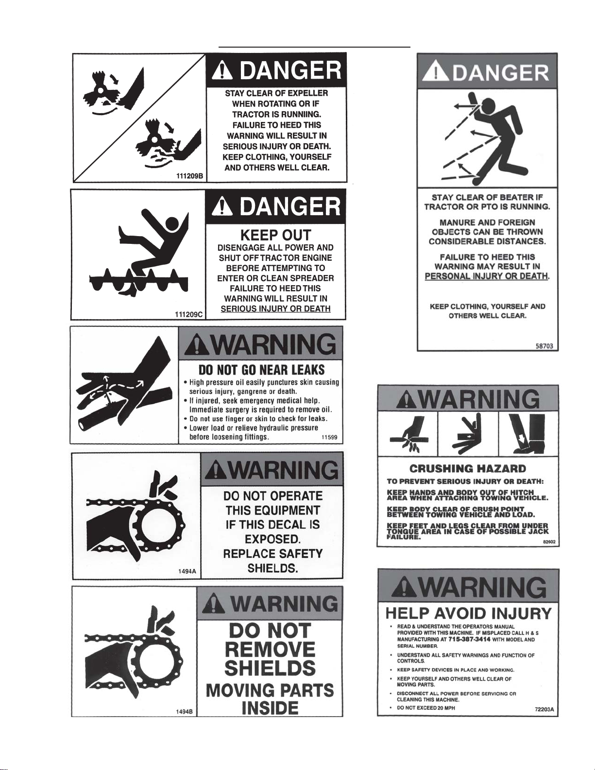
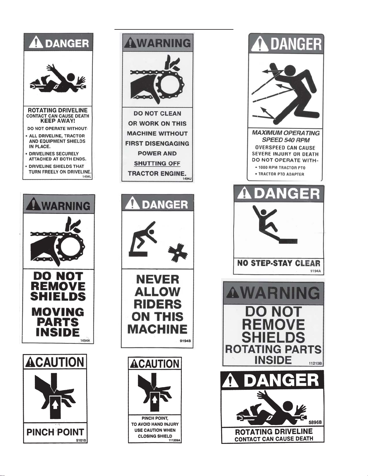
1494A 4 Do not operate this machine if this decal is exposed. Replace safety shields
1494B 1 Do not remove shields - moving parts inside
1494J 1 Do not clean or work on the machine without first disengaging power
1494K 1 Do not remove shields - moving parts inside
3494A 1 Remote Grease Decal
5896B 1 Rotating driveline
8496 4 H&S Decal
8354 2 H&S/Top Shot/Model # Decal - Side (5120)
8360 2 H&S/T op Shot/Model # Decal - Side (5126)
8350 1 H&S/T op Shot/Model # Decal - Rear (5120)
8355 1 H&S/Top Shot/Model # Decal - Rear (5126)
8353 2 Top Shot Logo Decal (2 - 5120 - 2 - 5126)
8351 2 Model # Decal Side (5120)
8357 2 Model # Decal Side (5126)
8349 1 H&S/Top Shot/Model # Decal - Front (5120)
8356 1 H&S/Top Shot/Model # Decal - Front (5126)
8515 1 Degree of Angle Decal-PTO Shaft
9194A 3 No step - stay clear
9194B 1 Never Allow Riders On This Machine
1 1210B 1 Do not remove shields
1 1599 4 Do not go near leaks
32320 1 Spiral Decal for Main Auger Shaf t-Rear
51010 4 Pinch Point
54033 1 Made in USA 3”
56877 1 540 RPM DECAL
58703 2 Stay Clear of Beaters
66076 2 Located Behind Shield
71188B 1 Jack S torage Position
72203A 1 Help avoid injury - Read and understand the operators manual
82602 2 Crushing Hazard
081312 1 Located behind sprocket
093020 16 Grease zerk decal
093366 1 Operators Manual
102196 1 Lube-CV Joint
1 11209A 1 Pinch Point
1 11209B 3 Stay clear of expeller when rotating or if tractor is running
111209C 4 Keep Out - Disengage all power and shut off tractor engine
1 1210A 1 Discharge gate opening decal
1 121 1176 2 Shear Bolts - Remove broken shear bolt before replacing
DCAMB 6 Amber Reflector
DCRED 3 Red Reflector
L W1 12901 1 Auger Height Indicator Decal
TFM97 1 SMV Decal
-33-
Page 36

DECAL LOCATION
51010
58703
DCAMB
111209B
1494K
56877
8515
1494L
1 1210A
9194B
1494B
51010 LW112901
54033
111209C
8350(5120)
8356(5126)
72203A
DCAMB
1494J
1 1599
9194A
10219682602 9194A
1494A
093020
DCRED
1 11209B
11210B
112-11176
3494A
081312
1494A
1 1599
1494A
1 12-11176
1494A
093020
1 1599
58703
51010
58703
1 11209B
51010
093020
-34-
1 11209B
DCAMB
Page 37

8354(5120)
8360(5126)
DCAMB
8496
DECAL LOCATION
8351(5120)
111209C
8357(5126)
8496
8353
1 1599
8353
8496
093366
093020
8351(5120)
8357(5126)
71 188B
DCAMB
DCAMB
58703
111209C
093020
8496
9194A
8354(5120)
8360(5126)
82602
DCAMB
8349(5120)
8355(5126)
31 15896B
1 11209A
102196
TFM97
DCRED
093020 51010
1 1599
111209C
DCRED
093020
32320
-35-
Page 38

TROUBLESHOOTING
NOTE:This Troubleshooting Chapter presents problems, causes and suggested remedies beyond the
extent of loose, worn or missing parts and it was developed with the understanding that the machine is
in otherwise good operating condition.
PROBLEM CAUSE REMEDY
1.) Material NOT
discharging from
expeller
2.) Auger will not turn Shear bolts are sheared.
3.) Expeller not turning Shear bolts have sheared.
4.) Chains are jumping
drive sprocket teeth
5.) Excessive chain
and/or sprocket
wear.
6.) Drive chain(s) will
NOT stay properly
tensioned.
7.) Uniformity of spread
or discharge rate
not acceptable
Discharge gate is NOT
open.
Expeller is NOT operating.
Expeller is obstructed.
Auger is NOT turning.
Open gate.
See item #3
Activate gate to free
obstruction
See item #2
Replace shear bolts.
Drive chain not on sprocket.
Reinstall/replace chain.
Sprockets MUST be
properly aligned.
Replace shear bolts
Drive chain not on sprocket.
Inadequate chain tension.
Sprocket teeth or chains
Reinstall/replace chain.
Adjust chain tension. See
details in Adjustments
Chapter.
Replace sprocket or chain.
excessively worn.
Sprockets are NOT
properly aligned.
Improper shear bolts being
used.
Inadequate chain tension.
Tensioner spring(s) NOT
properly adjusted.
Idler pivot arm(s) binding.
Tensioner spring(s) broken
Re-align sprockets.
Install proper shear bolts
listed in Operations
Chapter.
See item #6
Adjust tensioner spring(s).
Lubricate idler arm(s) to
pivot freely.
Replace spring(s).
or stretched.
Difficult to spread material. Change expeller or auger
speed sprockets.
-36-
Page 39

SERVICE NOTES
-37-
Page 40

SPECIFICATIONS
5120
Cubic Ft. Struck Level 268.6
Gallon Capacity 2009
Tank Length 16’
Overall Length 22’ 8”
Tank Width - Top 76”
Auger Diameter 24”
Poly Lined Tank Left Side
Overrunning Clutch Yes
Shear Bolt Protection Yes
PTO 540 RPM Std.
Expeller Size 40”
Front and Rear
Splashguards
Weight 6,860#
Side Loading Height 69” 68.5”
Height @ Rear Splash 70” 69.5”
Height @ Front Splash 76” 75.5”
Overall Width 85” 91”
Side Loading Height 72.5” 72”
Height @ Rear Splash 73.5” 73”
Height @ Front Splash 79.5” 79”
Overall Width 85” 91”
Side Loading Height 74.5” 74”
Height @ Rear Splash 75.5” 75”
Height @ Front Splash 81.5” 81”
Overall Width 85” 91”
Note: 385x22.5 Truck Tires will NOT fit on the Drop Axle
General Specs
1000 RPM Opt.
Yes
Drop Axle Specs
w/295 x 22.5 Tires
Standard Axle Specs
w/295 x 22.5 Tires
High Axle Specs
w/295 x 22.5 Tires
Drop Axle Specs
w/16.1 x 16.5 Tires
Standard Axle Specs
w/16.1 x 16.5 Tires or
385x22.5 Truck Tires
High Axle Specs
w/16.1 x 16.5 Tires or
385x22.5 Truck Tires
SPECIFICA TIONS ARE SUBJECT TO CHANGE WITHOUT NOTICE
-38-
Page 41

SPECIFICATIONS
5126
Cubic Ft. Struck Level 347
Gallon Capacity 2596
Tank Width - Top 87”
Tank Length 16’
Overall Length 22’ 8”
Auger Diameter 24”
Poly Lined Tank Left Side
Overrunning Clutch Yes
Shear Bolt Protection Yes
PTO 540 RPM Std.
Expeller Size 40”
Front and Rear
Splashguards
Weight 7,880#
Side Loading Height 81” 83” 84”
Height @ Rear Splash 82” 84” 85”
Height @ Front Splash 88” 90” 91”
Overall Width 103” 102” 105”
General Specs
1000 RPM Opt.
Yes
Specs
w/16.1 x 16.5
Tires
Tires
Specs
w/19L x 16.1
Specs
w/425x22.5
Tires
SPECIFICA TIONS ARE SUBJECT TO CHANGE WITHOUT NOTICE
Page 42

H&S MFGH&S MFG
H&S MFG
H&S MFGH&S MFG
products approved
for the
FEMAFEMA
FEMA
FEMAFEMA
..
CO CO
.
CO
..
CO CO
..
.
..
SEAL OF QSEAL OF Q
SEAL OF Q
SEAL OF QSEAL OF Q
UU
ALITYALITY
U
ALITY
UU
ALITYALITY
 Loading...