

Page 1

430W430W
430W
430W430W
MANURE SPREADERMANURE SPREADER
MANURE SPREADER
MANURE SPREADERMANURE SPREADER
OPERAOPERA
OPERA
OPERAOPERA
W ARNING
TT
OR’S MANUOR’S MANU
T
OR’S MANU
TT
OR’S MANUOR’S MANU
READ AND UNDERSTAND THIS MANUAL
BEFORE OPERATING THIS EQUIPMENT.
UNSAFE OPERATION OR MAINTENANCE OF
THIS EQUIPMENT CAN RESULT IN SERIOUS
INJURY OR DEATH.
ALAL
AL
ALAL
Revision #1
430W St arting Serial #317196
H&S MANUFACTURING CO.,INC.
P.O. BOX 768 (715) 387-3414 FAX (715) 384-5463
HSMFG1012 Part #59781
Manufactured By
MARSHFIELD, WISCONSIN 54449
Page 2

CONTENTS
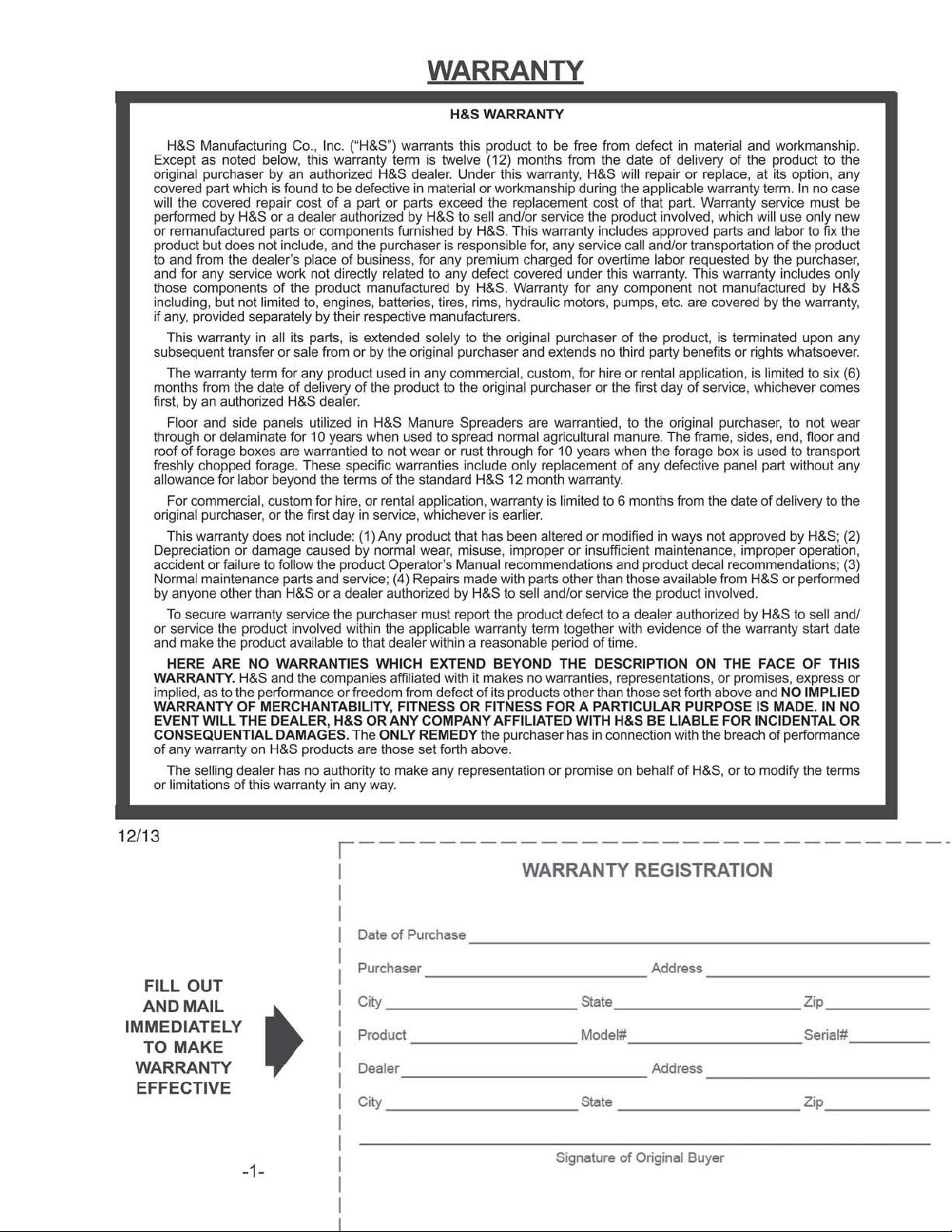
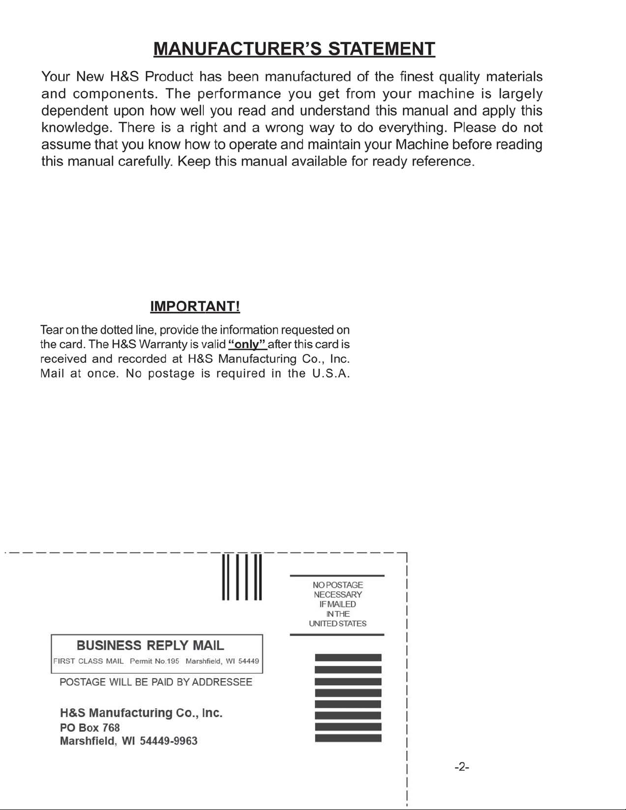
Warranty & W arranty Registration Card . . . . . . . . . . . . . . . . . . . . . . . . . . . . . . . . . . . . . . . . . . . . . . . 1-2
Dealer Pre-Delivery Checklist . . . . . . . . . . . . . . . . . . . . . . . . . . . . . . . . . . . . . . . . . . . . . . . . . . . . . . . . . 3
Dealer Delivery Checklist . . . . . . . . . . . . . . . . . . . . . . . . . . . . . . . . . . . . . . . . . . . . . . . . . . . . . . . . . . . . . 5
Safety Information - Be Alert Symbol . . . . . . . . . . . . . . . . . . . . . . . . . . . . . . . . . . . . . . . . . . . . . . . . . . . . 7
Safety Information - Explanation of Safety Signs . . . . . . . . . . . . . . . . . . . . . . . . . . . . . . . . . . . . . . . . . . 8
Safety Decals . . . . . . . . . . . . . . . . . . . . . . . . . . . . . . . . . . . . . . . . . . . . . . . . . . . . . . . . . . . . . . . . . . . . 9-10
Safety Information - Warning - Owner Must Read and Understand . . . . . . . . . . . . . . . . . . . . . . . . . . . 1 1
Cap Screw T orque Values . . . . . . . . . . . . . . . . . . . . . . . . . . . . . . . . . . . . . . . . . . . . . . . . . . . . . . . . . . . . 12
Set-Up & Assembly . . . . . . . . . . . . . . . . . . . . . . . . . . . . . . . . . . . . . . . . . . . . . . . . . . . . . . . . . . . . . . . . . 13
Transporting . . . . . . . . . . . . . . . . . . . . . . . . . . . . . . . . . . . . . . . . . . . . . . . . . . . . . . . . . . . . . . . . . . . . . . . . 13
Preparing for Operation . . . . . . . . . . . . . . . . . . . . . . . . . . . . . . . . . . . . . . . . . . . . . . . . . . . . . . . . . . . . . . 14
Operation . . . . . . . . . . . . . . . . . . . . . . . . . . . . . . . . . . . . . . . . . . . . . . . . . . . . . . . . . . . . . . . . . . . . . . . 15-16
Adjustments . . . . . . . . . . . . . . . . . . . . . . . . . . . . . . . . . . . . . . . . . . . . . . . . . . . . . . . . . . . . . . . . . . . . . 17-18
Service . . . . . . . . . . . . . . . . . . . . . . . . . . . . . . . . . . . . . . . . . . . . . . . . . . . . . . . . . . . . . . . . . . . . . . . . . . . . 19
Optional Equipment . . . . . . . . . . . . . . . . . . . . . . . . . . . . . . . . . . . . . . . . . . . . . . . . . . . . . . . . . . . . . . 20-21
Lubrication Guide . . . . . . . . . . . . . . . . . . . . . . . . . . . . . . . . . . . . . . . . . . . . . . . . . . . . . . . . . . . . . . . . 22-23
Decal Location . . . . . . . . . . . . . . . . . . . . . . . . . . . . . . . . . . . . . . . . . . . . . . . . . . . . . . . . . . . . . . . . . . 25-27
Trouble Shooting . . . . . . . . . . . . . . . . . . . . . . . . . . . . . . . . . . . . . . . . . . . . . . . . . . . . . . . . . . . . . . . . . . . . 24
Service Notes . . . . . . . . . . . . . . . . . . . . . . . . . . . . . . . . . . . . . . . . . . . . . . . . . . . . . . . . . . . . . . . . . . . . . . . 28
Specifications . . . . . . . . . . . . . . . . . . . . . . . . . . . . . . . . . . . . . . . . . . . . . . . . . . . . . . . . . . . . Inside Back Cover
Page 3
Page 4
Page 5

DEALER PRE-DELIVERY CHECK LIST
AFTER COMPLETION, DEALER SHOULD REMOVE AND RETAIN FOR RECORDS
After the Manure Spreader has been completely set-up, check to be certain it is in correct operating
order before delivering to the customer. The following is a list of point s to inspect. Check off each item
as you have made the proper adjustments and found the item operating satisfactorily.
Manure Spreader was not damaged in shipment. Check for dents and loose or missing
parts. Report damage immediately to H&S Manufacturing Co., Inc.
Manure Spreader has been correctly assembled according to instructions in this manual.
All bolts and fasteners are tight.
All shields and guards are in place and secured.
All grease fittings have been lubricated. Gearbox is filled to proper levels.
Lubrication Chapter of this manual for details.
See
Hoses and fittings if applicable, are properly attached and there are no visible leaks.
All drive chains are adjusted to proper tension. See Adjustment Chapter of this manual.
Decals are in place and legible.
Connect the Manure Spreader to a tractor and attach the PTO and make sure that the
PTO guards turns freely.
Connect the lights to the tractor if applicable. Lights and wiring functioning properly.
(Remove Dealer File Copy At Perforation)
Run the Manure Spreader and make sure all component s operate properly.
Hydraulic system if applicable, does not leak under pressure.
Model Number ______________________________________________
Serial Number ______________________________________________
Dealer’s Name ________________________________________________________________
Inspection Date _____________________________________________
Signature of Pre-Delivery Inspector ________________________________________________
-3-
Page 6

Intentionally Left Blank
-4-
Page 7

DEALER DELIVERY CHECK LIST
AFTER COMPLETION, DEALER SHOULD REMOVE AND RETAIN FOR RECORDS
This check list that follows is an important reminder of valuable information that should be passed
on to the customer at the time this Manure Spreader is delivered.
Check off each item as you explain it to the customer.
This delivery check list, when properly filled out and signed assures the customer that the
pre-delivery service was satisfactorily performed.
Explain to the customer that the pre-delivery inspection was made.
Explain to the customer all the safety precautions they must exercise when operating
this unit.
Explain recommended loads for different types of materials.
Explain to customer that regular lubrication is required for proper operation and long
life of machine.
(Remove Dealer File Copy At Perforation)
Show customer the lubrication section of Owner’s Manual.
Give the customer Owner’s Manual and make sure they read and understand all
operating and service instructions.
Have customer sign a completed “Warranty Registration,” and mail it promptly.
Date Delivered __________________________________
Dealer’s Name ________________________________________________________________
By __________________________________________________________________________
Signature of Original Buyer ______________________________________________________
Note: Warranty is not valid until warranty card is completed and returned to H&S Mfg. Co., Inc.
-5-
Page 8

Intentionally Left Blank
-6-
Page 9

SAFETY INFORMATION
BE
YOUR SAFETY
ALERT!
THIS SYMBOL IS USED THROUGHOUT THIS BOOK WHENEVER YOUR PERSONAL SAFETY
IS INVOLVED. TAKE TIME TO BE CAREFUL. REMEMBER: THE CAREFUL OPERATOR IS THE
BEST OPERATOR. MOST ACCIDENTS ARE CAUSED BY HUMAN ERROR. CERTAIN
PRECAUTIONS MUST BE OBSERVED TO PREVENT THE POSSIBILITY OF INJURY OR
DAMAGE.
H&S MANUF ACTURING CO., INC.
IS INVOL VED.
-7-
Page 10

SAFETY INFORMATION
Keep signs in good condition. Immediately replace any missing or damaged signs.
RECOGNIZE SAFETY INFORMATION
This is the safety-alert symbol. When you see this
symbol on your machine or in this manual, be alert to the
potential for personal injury .
Follow recommended precautions and safe operating
practices.
UNDERSTAND SIGNAL WORDS
A single word; DANGER, WARNING, or CAUTION is used
with the safety-alert symbol. DANGER identifies the most
serious hazards.
Safety signs with signal word DANGER or WARNING are
typically near specific hazards.
General precautions are listed on CAUTION safety signs.
FOLLOW SAFETY INSTRUCTIONS
Carefully read all safety messages in this manual, and all safety signs on your machine. Follow all
recommended precautions and safe operating procedures.
OBSERVE MAXIMUM TRANSPORT SPEED
The maximum transport speed for this implement is 32 km/h (20 m.p.h.).
Some tractors are capable of operating at speeds that exceed the maximum
transport speed of this implement. Regardless of the maximum speed capability
of the tractor being used to tow this implement, do not exceed the implement’s
maximum transport speed.
Exceeding the implements maximum transport speed can result in:
* Loss of control of the tractor/implement combination
* Reduced or no ability to stop during braking
* Implement tire failure
* Damage to the implement structure or its components
Use additional caution and reduce speed when towing under adverse surface
conditions, when turning, and when on inclines.
Do not attempt transport if the fully loaded implement weighs more than 1.5 times
the weight of the tractor.
-8-
Page 11

SAFETY INFORMATION
-9-
Page 12

SAFETY INFORMATION
-10-
Page 13

SAFETY INFORMATION
TRACTOR:
This operators manual uses the term “Tractor” when identifying the power or the towing source.
WARNING
TO PREVENT SERIOUS INJURY OR DEATH
BEFORE YOU ATTEMPT TO OPERATE THIS EQUIPMENT, READ AND STUDY THE FOLLOWING
INFORMATION. IN ADDITION, MAKE SURE THAT EVERY INDIVIDUAL WHO OPERATES OR WORKS
WITH THIS EQUIPMENT, WHETHER FAMILY MEMBER OR EMPLOYEE, IS FAMILIAR WITH THESE
SAFETY PRECAUTIONS.
KNOW HOW TO ST OP UNLOADING MECHANISM BEFORE STARTING IT.
If the machine becomes clogged,
and allow all mechanisms to stop before cleaning or working on the machine.
DO NOT get off the tractor while the Manure S preader is in operation.
DO NOT attempt to perform maintenance or repair with tractor running and PTO or hydraulic lines
hooked up.
DO NOT step up on machine at any time.
NEVER manually feed material into the beaters.
DO NOT allow minors to operate or be near the machine.
DO NOT ALLOW PERSONNEL OTHER THAN THE QUALIFIED OPERATOR NEAR THE MACHINE.
Before starting tractor, be sure PTO shields turn freely and PTO is securely locked to tractor.
DO NOT clean, adjust, or lubricate the machine when any part is in operation.
Keep hands, feet, and clothing away from beaters when they are revolving.
Loose or floppy clothing should not be worn by the operator.
Be sure the machine is clear of people, tools, and other objects before engaging PTO.
DO NOT step over power take off shaft. Stay clear of PTO at all times.
disengage the PTO. S top the tractor engine, remove ignition key,
NEVER start Manure S preader until all guards and safety shields are secured in place.
STAY CLEAR of Hydraulic Lines. They may be under extreme pressure or heat.
H&S always takes the operator and his safety into consideration and guards exposed moving parts for
his protection. However, some areas cannot be guarded or shielded in order to assure proper operation.
In addition, the operators manual and decals on the machine itself warn you of further danger and
should be read and observed closely .
Study The Above Safety Rules
ATTENTION - BE ALERT - YOUR SAFETY IS INVOLVED
-11-
Page 14

-12-
Page 15

SET -UP & ASSEMBLY
Note: Determine right and left side of spreader by viewing it from the rear . If instructions
or parts list s call for hardened bolts, refer to Cap Screw T orque Value page to identify.
PREPARING MANURE SPREADER
The Manure Spreader may be shipped without the wheels/tires installed.
1. Attach the wheels with tires, using the lug nuts furnished and torque the mounting hardware to
the appropriate torque. Wheel bolts should be tightened at 100 ft./lbs. of torque.
2. Check the tires and inflate to the recommended pressure(295/75RX22.5 tires to 75 to 80 psi.).
3. Check for proper assembly and adjustment and make sure that all bolts are tightened.
4. Securely retighten after a few hours of operation, as bolts can loosen up on new machinery.
5. Lubricate the machine completely, check the oil level of the gearbox, fill if necessary.
TRANSPORTING
REFLECTORS/SMV
When transporting on the highway , connect the spreader to
the tractor with a lighting power cord. The lighting system
is to be connected to the 7 pin power receptacle (per
SAEJ560B) on your tractor. If your tractor is not equipped
with the proper receptacle, see your tractor dealer for
details. Make sure lights are functioning properly . Regularly
clean the reflective tape at the rear of the spreader . There is
a holder provided for your SMV sign. Unless otherwise
prohibited, use a slow-moving vehicle emblem. Never tow
the manure spreader on a public highway at a speed greater
than 20 m.p.h. (32 kph).
(Shown w/optional upper beater)
SAFETY CHAIN (Optional)
Follow state and local regulations regarding use of a safety chain and transport lighting when towing farm
equipment on public highways. A proper safety chain should be used to retain the safety connection
between the towing and towed machines, in the event of separation of the primary attaching system.
Check with local law enforcement agencies for your own particular regulations. Never tow the manure
spreader on a public highway at a speed greater than 20 m.p.h. (32 kph).
1. Chain is sufficiently slack to allow turns and movements of either the tractor or the manure spreader ,
without placing tension on the chain.
2. Chain is of sufficient strength to hold the decoupled implement (and its load) and tow it to the
shoulder .
-13-
Page 16

PREPARING FOR OPERATION
TRACTOR CONNECTIONS
Tractor Hitch
Fasten the spreader hitch to the drawbar with a hitch pin with
a safety locking device. Remove the weight from the jack (jack
is not to be used when spreader is loaded). Remove jack from
pipe mount and place on convenient storage mount located on
the top of left hitch channel. This allows protection of jack from
tractor tires during turns. The hitch of the spreader is designed
for a standardized tractor hitch. Adjust the drawbar so that it is
13 to 17 inches above the ground. Extend or shorten it so that
the horizontal distance from the end of the tractor power takeoff
shaft to the center of the hitch pin hole is 14 inches for 540 PTO
and 15-3/4” for 1000 PTO as shown in drawing. An improperly
located hitch point may cause damage to the universal joints of
the power takeoff. Secure the drawbar so that the hitch pin hole
is directly below the power drive line.
15-3/4” for 1000 RPM
PTO
Attach the PTO of the spreader to the tractor by sliding the spring loaded locking collar on PTO yoke
rearward, then sliding it onto the tractor PTO shaft. Release spring loaded collar. Be sure the pins fall
into the groove of the tractor PTO shaft and collar snaps forward into locking position.
CAUTION: Do not use a steel hammer to aid in joining PTO parts.
If this implement is attached to a tractor with a clevis
hitch (hammer-strap) style drawbar, the
hammer-strap must be removed to prevent
damage to the IID guarding and the IID telescoping
members. [See Figure 1]
If this implement is attached to a tractor with an
offset in the drawbar, be certain it is in the down
position to prevent damage to the IID guarding and
the IID telescoping members. [See Figure 2]
Manure Spreader Speed Control
Attach the manure spreader speed control/beater engage/disengage rope to a convenient point on the
tractor.
-14-
Page 17

OPERATION
EMERGENCY SHUTDOWN
If a foreign object becomes lodged in the beater area and shears the shear bolt, disengage the PTO. S top
the tractor engine, remove the ignition key , and allow all mechanisms to stop before cleaning or working
on the spreader.
WARNING: Some photographs used in the following pages show guards or shields
removed for clarification. NEVER operate machine until these guards or shields are in
proper operating position.
LOADING
In freezing weather, make cert ain that hydraulic tail gate (if equipped with one) is not frozen to the sides or
on the floor of the spreader. Make sure the apron chain is not frozen to the spreader floor or any lump s of
manure are frozen to the floor. Begin loading the spreader at the front end and work toward the rear until
loading is completed. Loading this way permits the material to be spread uniformly . Loading front to rear
is particularly important when the spreader is loaded by a mechanical loader because this type of load
requires more power to spread than others loads. When hauling extremely heavy materials with a large
portion of dirt, it may be necessary to reduce the load size to prevent excessive shear bolt breakage.
Never dump material onto the beater. Do not use extra sideboards. Do not overload spreader.
Overloading decreases spreading effectiveness. Do not load more than 15 inches above the beater .
SPREADING - 2 SPEED
NOTE: T wo speed drive mechanism and beater engage/disengage are controlled be one rope leading to
the tractor.
1. When ready to unload, make sure beater is in the engaged position and low speed indicator is
visible through low speed hole in panel of spreader .
2. Raise the hydraulic endgate.
3.
4. Increased apron speed, if desired, can be accomplished by steadily pulling on the rope until it
5. When the Manure Spreader is almost empty, the bed can be cleaned by shifting into clean out
6.
7. Do not operate the Manure Spreader with a PTO speed greater than 540 RPM’s unless necessary
Engage the tractor PTO shaft slowly.
stops. S peed select indicator should now be visible through the high speed hole. Beater will
continue to operate and apron speed will be increased.
position. Apply a steady pull on the rope until it stop s and speed indicator is visible in the clean out
hole. In this position, the beater will stop and the apron will continue to operate at the same speed
as in high speed position, thus saving unnecessary driving.
When spreader is empty , shut of f tractor PTO. Pull control rope until speed select indicator snaps
into low speed. This will re-engage beater for the next load. DO NOT SHIFT FROM CLEAN OUT
TO LOW SPEED WITH THE TRACTOR PTO RUNNING.
sprocket changes have been made.
Low Speed Clean Out
High Speed
-15-
Page 18

OPERATION
SPREADING - WITH OPTIONAL HYDRAULIC DRIVE
1. Engage tractor PTO shaft slowly. Beater is always in the engaged position, therefore, engaging
tractor PTO will automatically start beater.
2. Raise the hydraulic tailgate.
3. Open hydraulic valve on tractor connected to speed control valve on Manure Spreader.
4. Control speed of apron by turning speed control handle clockwise to increase speed,
counter-clockwise to decrease speed.
5. When the Manure Spreader is almost empty, the bed can be cleaned out by disengaging tractor
PTO (which will stop beater), and increasing apron speed by turning control handle clockwise,
thus saving unnecessary driving time.
FAILURE TO FOLLOW THE RECOMMENDED ADJUSTMENTS WILL VOID WARRANTY
-16-
Page 19

ADJUSTMENTS
DRIVE CHAIN
To adjust front drive chain, loosen jam nut turn nut on adjusting
rod (located at the right hand front side of spreader) clockwise.
There should be 1/2” deflection at the center of the drive chain.
Over tightening or too loose of a chain will result in excessive
wear on the bearing, chain and sprockets. Retighten jam nut.
Tightener Bolt
APRON SPEED AND BEATER CONTROL
One cable controls both the beater clutch and two speed
clutch. To compensate for wear or stretching of this cable,
adjust the turnbuckle behind shield at the front of the
spreader.
Turnbuckle
Shields Removed for Clarity
TWO SPEED CLUTCH
If clutch control yoke becomes worn, it may be necessary to adjust the high speed clutch so it engages
and disengages completely . Adjustment to compensate for this wear is made by sliding spring stop (A)
on control rod closer to the clutch engaging lever. Initial adjustment should be made as follows: Distance
(B) between spring stop and jam nut is seven (7”) inches. Distance (C) between jam nut and shifting rod
bracket is one-eighth (1/8”) inches. This distance may be achieved by adjusting the turnbuckle at front of
spreader.
WHEEL HUBS
T o adjust wheel hubs, tighten the castellated nut on
the spindle to the point where there is no end-play
and a slight drag on the bearings. Replace the
cotter key with a new one of the correct size.
-17-
Page 20

ADJUSTMENTS
BEATER CLUTCH ADJUSTMENT
It may be necessary to compensate for wear in the beater clutch and clutch control yoke. When properly
adjusted the moveable jaw clutch should have one-quarter (1/4”) inch (distance C) between clutches
when disengaged. To adjust, loosen jam nut (A) holding spring bracket. With beater disengaged (clean
out position), tighten nut (B) against shifter lever bracket until the proper distance between clutch jaws is
reached. Overtightening will cause beater not to fully engage and cause excess tension on cable. Tighten
lock nut (D) so there is one thirty-second (1/32”) inch clearance between clutch jaws (E).
APRON
1. Adjust the apron by loosening the mounting bolt s on
the chain slides on the outside of the frame. Mounting
bolts shown in the drawing.
2. Tighten the adjusting bolt s until the apron chain clears
the underside of the axle by 1 inch.
3. Retighten jam nut.
Mounting Bolts Adjusting Bolt
NOTE: Tighten the adjusting bolts (on each front corner) equally on each side so that the apron slats run
parallel with the ends of the bed. The apron will be damaged if the machine is operated with one end of the
apron slats running ahead of the opposite end. Do not tighten the apron chains excessively.
APRON WORM DRIVE CHAIN
The apron worm drive chains are kept tight
with a spring type tightener that does not
require adjustment. However, periodic
inspection should be made to check for wear.
-18-
Page 21

SERVICE
SHEAR BOLTS - Main Drive
The beater and the apron drive are protected by
one shear bolt located on the front end of the side
drive shaft (left side of spreader). T wo spare shear
bolts are provided. Shearing of the bolts is normally
due to foreign objects in the manure or starting
the spreader PTO too quickly with high tractor
RPM’s. Always use H&S shear bolts when
replacing shear bolts.
Spare Shear Bolts
Shear Bolt
SHEAR BOLTS - Apron Drive
The worm gearbox and apron are protected by two shear bolts.
One on the driven high speed sprocket (A) and one on the
low speed sprocket (B). Two spare shear bolts are provided
(C). Shearing of these bolts is normally due to the apron
being frozen fast to the floor, or catching on frozen “chunks”.
Occasionally the shear bolts will shear due to the spreader
being overloaded. Always determine the cause of failure, and
eliminate the cause before replacing the shear bolt, using H&S
shear bolts when replacing shear bolts.
Shields Removed for Clarity
NOTE: Normal apron speeds at 540 RPM are: low speed
4-1/2 fpm, high speed and clean out position 8-1/2 fpm. If the
apron is not moving at these speeds, especially in high or
clean out, check and replace the high speed shear bolt (A).
Failure to do so will result in serious damage to the
sprocket and shaft.
Shields Removed for Clarity
ABC
BEATER
When replacing beater paddles, the sharp edges of the teeth
must lead in the direction of beater travel. On the right half
of the beater the teeth must point to the right side of the
spreader. On the left half of the beater the teeth must point
to the left side of the spreader . Always use H&S special grade
5 bolts, washers, and nuts when replacing. Torque to 60
foot lbs.
(Shown w/optional upper beater)
WHEEL BEARING LUBRICATION, CLEAN & RE-PACK INSTRUCTIONS
Wheel hubs are equipped with a grease zerk for regular maintenance. Annually disassemble and clean
parts in solvent. Reassemble bearings per instructions in the Service Chapter and tighten the
castellated nut on the spindle to the point where there is no end-play and a slight drag on the bearings.
Replace the cotter key with a new one of the correct size, bend cotter pin over and re-install cap.
-19-
Page 22

OPTIONAL EQUIPMENT
REAR PAN
The rear pan shown is optional equipment.
UPPER BEATER
An optional upper beater is available and will provide a more
uniform spreading in heaped and heavily matted material. The
upper beater may be used with hydraulic endgate.
-20-
Page 23

OPTIONAL EQUIPMENT
HYDRAULIC DRIVE
An optional hydraulic drive unit is available to convert from two speed to variable speed hydraulic drive.
Hydraulic drive may be used as a two or four hose tractor hook-up.
Front Control Panel Hydraulic Motor
Shields Removed for Clarity
-21-
Page 24

LUBRICATION
GENERAL INFORMATION
IMPORTANT: Catch and dispose of fluid per local waste disposal regulations whenever service is
performed on hydraulic components, valves, cylinders, hoses, etc.
GREASE FITTINGS
There are numerous grease fittings on the spreader. The operator should become familiar with all
lubrication points and establish a systematic routine to insure complete and quick lubrication of the
machine. If these are lubricated properly and often enough, it will prolong the life of the spreader.
(Grease every 10 hours, also before and after power washing.) Make certain that the grease fittings
are free of paint and dirt, force a high-quality grease into them until the grease comes out around the
shaft on the sleeve-type bearings. On the sealed ball bearings, grease should be added slowly until a
slight bead forms at the seals indicating the correct amount of lubricant. Wipe off excess grease to
prevent the accumulation of chaff and grit around the bearings.
DRIVE CHAINS
Lubricate the drive chains with a light machine oil. Keep chains aligned with sprockets, this will lengthen
the life of the sprockets and chain. Lubricate chains often.
GEARBOX
Before using your new machine, check the oil in the main apron drive and beater drive gearbox.
Keep the gearbox filled to the oil plug on the side of the gearbox as shown with 80/90 gear lube.
Beater
Gearbox
Oil
Level
Main
Apron
Gearbox
Oil
Level
PTO ASSEMBLY
Keep the male and female shafts of the PTO well lubricated and free sliding. Failure to observe this
precaution will result in excessive pressure being required to collapse or extend the assembly while
subject to operating torque. This excessive force may damage the main shaft bearings. Never lubricate
the shield surfaces. the shield surfaces must be kept dry, as dirt accumulation on them will cause the
shields to bind and not rotate. Dented or damaged PTO shields, will also result in excessive force being
applied against the jackshaft. If at any time the shields do not turn freely, they should be checked to
determine the cause, and repaired or cleaned. To avoid damage to the main drive bearings, avoid turning
sharp corners while the PTO is running. Start and Stop the PTO slowly to avoid damage to the drive line.
-22-
Page 25

LUBRICATION
GREASE ZERK LOCATION - Grease every 10 Hours
A. (3) PTO Shaft
B. (2) Front jack shaft bearings.
C. (2) Rear Drive Shaft
D. (1) Beater
E. (2) Worm Drive Gearbox
F. (4) Side Shaft(Models 370/430)
G . (3) Side Shaft(Model 310)
NOTE: Shields removed in some pictures for clarity. DO NOT OPERATE WITH SHIELDS REMOVED
M L N K
H. (2) Tailgate Arms
I. (2) Axle Pivot(Model 310)
J. (4) Axle Pivot (Model 370430)
K. (1) Beater Clutch ControlY oke
L. (1) Two Speed Clutch Control Yoke
M. (1) Two Speed Clutch Throwout
N. (1) Rear Support Bearing
O. (4) Zerks on hubs (1 on each hub)
Shields Removed for Clarity E
H
F-G I-J
O
C D
AB
WHEEL BEARING LUBRICATION, CLEAN & RE-PACK INSTRUCTIONS
Wheel hubs are equipped with a grease zerk for regular maintenance. Annually disassemble and clean
parts in solvent. Reassemble bearings per instructions in the Service Chapter and tighten the
castellated nut on the spindle to the point where there is no end-play and a slight drag on the bearings.
Replace the cotter key with a new one of the correct size, bend cotter pin over and re-install cap.
-23-
Page 26

TROUBLE SHOOTING
WARNING:
MAKE SURE THAT THE TRACTOR IS SHUT OFF AND THE SPREADER CAN NOT
MOVE BEFORE SERVICING THE MANURE SPREADER. MAINTENANCE AND
REPAIR SERVICE WORK TO BE PERFORMED BY A QUALIFIED SERVICE PERSON
ONLY.
TROUBLE... POSSIBLE CAUSE... POSSIBLE REMEDY...
Beater Does Not Turn PTO Not Turning Engage Tractor PTO
Beater Not Engaged Engage Beater
Main Drive Shear Bolt Sheared Replace Main Drive Shear Bolt
Front Drive Chain Off, Replace or Repair Front Drive Chain
Broken, or Missing
Control Cable out of Adjustment Adjust Control Cable
Splined Beater Insert W orn or Replace Splined Beater Insert and
Splines Sheared Off Gearbox Output Shaft
Beater Will Not Disengage Control Cable Out of Adjustment Adjust Control Cable
Control Linkage Binding Check Control Linkage, Make Sure
It Is Free Moving
Apron Does Not Turn PTO Not Turning Engage Tractor PTO
Main Drive Shear Bolt Sheared Replace Main Drive Shear Bolt
Front Drive Chain Off, Broken, Replace or Repair Front Drive Chain
or Missing
Apron Only Drives In Low High Speed Shear Bolt Replace Sheared or Missing
Sheared or Missing Shear Bolt
Apron only Drives in High Low Speed Shear Bolt Replace Sheared or Missing
Sheared or Missing Shear Bolt
Dog or Dog Spring Worn, Replace Worn, Broken or Missing
Broken or Missing Dog or Dog Spring
Shear Plate Worn Replace Shear Plate
-24-
Page 27

DECAL LOCATION
Your H&S Manure Spreader was manufactured with operator safety in mind. Located on the manure
spreader are various decals to aid in operation, and warn of danger or caution areas. Pay close attention
to all decals on your Manure Spreader.
DO NOT REMOVE ANY OF THESE DECALS. IF DECALS ARE LOST, DAMAGED, OR
IF MANURE SPREADER IS REPAINTED, REPLACE DECALS. REMEMBER: DECALS
ARE FOR YOUR PROTECTION AND INFORMATION.
Listed below are the decals on your Manure Spreader. These decals may be ordered individually by
part
number or by ordering a complete set.
PART # QTY DESCRIPTION
1494A 3 Warning - Do Not Operate
1494B 2 Warning - Do Not Remove Shields
1494H 1 Danger - Stay Clear
1494J 3 Warning - Do Not Clean or Work
1494K 3 Warning - Do Not Remove Shields
1494L 1 Danger - Rotating Driveline
093020 19 Grease Zerk
11599 1 Warning - Stay Clear of Leaks
1 11593A 2 Danger - Stay Clear of Beater
1 11593C 2 Warning - S t ay Clear of Endgate
12794 2 Warning - Do Not Remove Shields
1 121 1 1 76 2 Shear Bolts
31 1 1 Patent Number
3187 1 Speed Indicator (only on if equipped with hydraulic drive)
32222 4 Clear Protector
3494A 2 Remote Grease - Axle Pivot
54033 1 Made in USA 3”
66076 4 Located Behind Shield
71188B 1 Jack S torage Position
71 188H 1 Beater/Apron Control
71494A 3 Warning Do Not Operate
72203A 1 Warning - Help Avoid Injury
82602 1 Warning - Crushing Hazard
9194A 2 Danger - No S tep
9194B 1 Danger - Never Allow Ride
093466 1 540 RPM
DCAMB 5 Amber Reflector
DCRED 2 Red Reflectors
H71594 1 Model Decal for Top Beater
8405 1 Decal-430W Spreader Left 66"W x 7"H
8406 1 Decal-430W Spreader Right 69"W x 8"
8407 1 Decal-430W Spreader Front 48"W x 5"H
-25-
Page 28

DECAL LOCATION
12794 093020 11593C 1494K
1494K
11211176
UNDER
SHIELD
1494A
DCAMB 8405
71188H (TWO
SPEED DECAL)
1494A
71949A
UNDER
SHIELD
311
8407
1494J
54033
9194B
1 1593A
1494J
3494A
72203A
DCAMB
1494K
3187
(HYDRAULIC
DRIVE DECAL
IF EQUIPPED)
1 1599
1494B
093466
1494L
71494A
-26-
82602
9194A 71188B 1494B
Page 29

DECAL LOCATION
H71594 111593C
1494H
3494A DCAMB1494J
1 11593A
8406
093020
8407
1494B
9194A1494BDCAMB
DCRED
1 1211176 1494A
3494A
-27-
Page 30

SERVICE NOTES
-28-
Page 31

SPECIFICATIONS
310 370 430
T op Flare Wi dth. . . . . . . . . . . . . . . . . . . . . . . . . . . . 68’. . . . . . . . . . . . . . . 68”. . . . . . . . . . . . . . . . . . .68”
Inside Width. . . . . . . . . . . . . . . . . . . . . . . . . . . . . . . .59-3/4”. . . . . . . . . . . .59-3/4”. . . . . . . . . . . .59-3/4”
Inside Length. . . . . . . . . . . . . . . . . . . . . . . . . . . . . . .15’7”. . . . . . . . . . . . . .16’6”. . . . . . . . . . . . . . . 16’6”
Inside Depth. . . . . . . . . . . . . . . . . . . . . . . . . . . . . . . 28-3/8”. . . . . . . . . . . .34-3/8”. . . . . . . . . . . .40-3/8”
Overall Width w/295/75R22.5 T ires. . . . . . . . . . . . 97”. . . . . . . . . . . . . . . 97”. . . . . . . . . . . . . . . . . .N/A
Overall Width w/16.5 x 16.1 T ires. . . . . . . . . . . . . .107”. . . . . . . . . . . . . . 107”. . . . . . . . . . . . . . . . 107”
Overall Length. . . . . . . . . . . . . . . . . . . . . . . . . . . . . .21’-1 1-1/2”. . . . . . . . .23’-2-1/2”. . . . . . . 23’-2-1/2”
Overall Loading Height (T op of Flare). . . . . . . . . . 51-1/2”. . . . . . . . . . . .57-1/2”. . . . . . . . . . . .63-1/2”
Overall Height w/Hyd. Endgate. . . . . . . . . . . . . . . .55”. . . . . . . . . . . . . . . 61”. . . . . . . . . . . . . . . . . . 67”
Diameter of Beater. . . . . . . . . . . . . . . . . . . . . . . . . .29”. . . . . . . . . . . . . . . 29”. . . . . . . . . . . . . . . . . . 29”
Weight w/295/75R22.5 T ires. . . . . . . . . . . . . . . . . 4190 Lbs. . . . . . . . . .4920 Lbs . . . . . . . . . . . .N/A
Weight w/16.5 x 16.1 T ires. . . . . . . . . . . . . . . . . . . 4200 Lbs. . . . . . . . . .4930 Lbs. . . . . . . .5220 Lbs
Capacity (Old Rating). . . . . . . . . . . . . . . . . . . . . . . .310 Bu. . . . . . . . . . . .370 Bu . . . . . . . . . . .430 Bu.
Capacity - Cu. Ft. S truck Level. . . . . . . . . . . . . . . .185. . . . . . . . . . . . . . .235. . . . . . . . . . . . . . . . . 275
Rear Hydraulic Endgate. . . . . . . . . . . . . . . . . . . . . S tandard . . . . . . . . . .Standard . . . . . . . .S tandard
Semi Liquid Rear Pan. . . . . . . . . . . . . . . . . . . . . . .Optional . . . . . . . . . . Optional . . . . . . . . . Optional
Upper Beater . . . . . . . . . . . . . . . . . . . . . . . . . . . . . . Optional. . . . . . . . . . .Optional . . . . . . . . . Optional
Drive. . . . . . . . . . . . . . . . . . . . . . . . . . . . . . . . . . . . . . . . T wo Speed Clutch to W orm Gear All Models
Worm Gear . . . . . . . . . . . . . . . . . . . . . . . . . . . . . . . Bronze . . . . . . . . . . . .Bronze . . . . . . . . . . . Bronze
V ariable Speed Hydraulic Drive. . . . . . . . . . . . . . . Optional . . . . . . . . . . .Optional . . . . . . . . .Optional
Front Splash Panel. . . . . . . . . . . . . . . . . . . . . . . . . .Sandard. . . . . . . . . . .Standard . . . . . . . .Standa rd
PTO S peed. . . . . . . . . . . . . . . . . . . . . . . . . . . . . . . . 540 RPM. . . . . . . . . .540 RPM . . . . . . . 540 RPM
* SPECIFICATIONS ARE SUBJECT TO CHANGE WITHOUT PRIOR NOTICE.
Page 32

H&S MFGH&S MFG
H&S MFG
H&S MFGH&S MFG
products approved
for the
FEMAFEMA
FEMA
FEMAFEMA
..
CO CO
.
CO
..
CO CO
..
.
..
SEAL OF QSEAL OF Q
SEAL OF Q
SEAL OF QSEAL OF Q
UU
ALITYALITY
U
ALITY
UU
ALITYALITY
 Loading...