

HRW HPE-BNMBUS User Manual
HPE-BNMBUS – M-Bus (EN1434-3) Gateway to BACnet MS/TP
FW 4.01, from March, 2018
250 point
M-Bus devices may be connected to the gateway for read access of up to 250 M-Bus data-points
Typical Applications
BACnet MS/TP network integration of M-Bus devices:
Feature Summary
Default M-Bus Settings
The gateway may be configured for any M-Bus device. As an initial guide (example) the factory settings
include meter and point addressing for the Sontex SuperCal 531 energy integrator. Ultimately the user
must configure the meter and point data base to suit the specific devices connected in the M-Bus
network.
Sontex SC531 example points:
integration of M-Bus (EN1434-3) conforming devices in to BACnet MS/TP networks. Up to 40
Hot water or chilled water energy meters (BTU meters)
Water meters
Electricity meters
Pulse converters
Integrated M-Bus network driver, up to 40 M-Bus devices
Primary or Secondary addressing
Diagnostic function for M-Bus point DIF/VIF identification
With or without common ‘DVIF’ data point assigned to each device address configuration point
Beyond the device address point DVIF assignment, independent point configuration per-device
M-Bus point DIF-only scan option possible (independent of point VIF value)
Settable network scan period (for suitable battery powered meters, battery conservation)
Primary address 0
Common DVIF for Energy (kWh, assigned to the Primary address point, point 4 / AV4)
Volume at point 5 (AV5)
Flow temperature at point 6 (AV6)
Return temperature at point 7 (AV7)
Power (kW) at point 8 (AV8)
Flow rate (m
3
/h) at point 9 (AV9)
HRW Limited Unit E, 11/F, Sun Ying Industrial Centre Ph +852 2546 7402
9 Tin Wan Close, Tin Wan Fax +852 2546 7403
Hong Kong www.hrw.hk

OPERATION OVERVIEW .................................................................................................................................... 3
BACNET DEVICE ................................................................................................................................................... 3
M-BUS NETWORK GATEWAY ................................................................................................................................. 3
BACNET PRIORITY ARRAY ............................................................................................................................... 3
TERMINAL MODE ................................................................................................................................................ 4
HYPERTERMINAL SETTINGS ................................................................................................................................... 4
Additional Settings ............................................................................................................................................ 5
Connecting at 76800 Baud Rate ....................................................................................................................... 5
Saving HyperTerminal Settings ........................................................................................................................ 5
BREAK IN TO TERMINAL MODE .............................................................................................................................. 5
BACNET CONFIGRATION COMMANDS ......................................................................................................... 6
M-BUS CONFIGURATION COMMANDS .......................................................................................................... 7
M-BUS READING STRUCTURE .......................................................................................................................... 8
DATA POINT SEARCH .............................................................................................................................................. 8
DATA POINT ADDRESS ............................................................................................................................................ 8
EXAMPLE RSP PAGES ............................................................................................................................................ 9
GATEWAY DATA BASE STRUCTURE............................................................................................................ 10
GATEWAY POINT TYPES ....................................................................................................................................... 10
COMMON DVIF.................................................................................................................................................... 10
GATEWAY POINT STRUCTURE ...................................................................................................................... 11
COMMON DVIF.................................................................................................................................................... 11
METER ADDRESS (M) .......................................................................................................................................... 11
Primary Addressing ........................................................................................................................................ 11
Secondary Addressing .................................................................................................................................... 12
METER ADDRESS (A) ........................................................................................................................................... 12
DATA POINT (D) .................................................................................................................................................. 12
EXTENSION POINT (X) .......................................................................................................................................... 15
TIME SCANNED POINT (T) .................................................................................................................................... 15
DATA BASE MAPPING TOOL........................................................................................................................... 16
TERMINAL OPERATION ................................................................................................................................... 16
DOWNLOAD TEXT FILE ........................................................................................................................................ 17
ENABLE M-BUS PORT .......................................................................................................................................... 18
SCAN M-BUS NETWORK ...................................................................................................................................... 18
DIAGNOSTIC DISPLAY .......................................................................................................................................... 18
INSTALLATION & COMMISSIONING ........................................................................................................... 20
POWER & RS485 .................................................................................................................................................. 20
M-BUS ................................................................................................................................................................. 21
CONNECTIONS .................................................................................................................................................... 22
DIMENSIONS ........................................................................................................................................................ 22
TECHNICAL DATA ............................................................................................................................................. 23
ORDERING INFORMATION ............................................................................................................................. 23
HPE-BNMBUS ................................................................................................................................................... 23
ACCESSORIES ....................................................................................................................................................... 23
OTHER HP_BN SERIES DEVICES .......................................................................................................................... 23
HRW HPE-BNMBUS V401 Manual 180307 E. & O. E. / Subject to change without notice Page 2 of 24

Operation Overview
The gateway comprises two sections; the BACnet MS/TP device and the M-Bus network reading data
base.
BACnet Device
The gateway is BTL listed, conforming to the BACnet standard’s requirements for device & object
discovery and network communication initiations and responses.
During commissioning the following should be configured:
Node # (local network unique number)
Device Instance (system-wide unique number)
MS/TP network baud rate
Maximum Master (MM), set to the highest node number existing on the network, for limiting
network traffic to only those devices that exist on the network
250 AV objects relating to the M-Bus network devices’ data points being read, AV4…AV253
M-Bus Network Gateway
250 device data points may be configured, from up to 40 M-Bus devices. Each data point constitutes a
BACnet object (AV).
It is important to have the M-Bus device manufacturer’s manual available to assist with M-Bus point
address settings although the gateway’s Diagnostic function means the available data points can be
identified without the manufacturer’s manual if need be. Each required data point should be configured
in the order that it appears in the manufacturer’s point table (or in the order that they appear in the
Diagnostic response).
The gateway data base consists of:
1. One data point, the ‘DVIF’, which should be the first M-Bus user-required data point as it
appears in the data sequence. The data returned according to the DVIF point address may be
assigned to any AV that is configured as a meter addressing point
2. Starting with gateway point 4 (AV4) the first meter Primary or Secondary address point
3. Starting with point 5 (AV5) a sequential selection of required M-Bus data points related to the
preceding meter address point
4. Repeat step 2 & 3 for each subsequent M-Bus device
BACnet Priority Array
The BACnet protocol utilises a Priority Array for each object to enable various network devices to take
control of a device’s object based on the level of need. The priorities are in the range 1 (high priority) to
16 (Auto operation).
In respect of this device:
The point database objects are NULL priority, signified by ‘17’ when viewing the points in
engineering Terminal mode
Manually overriding a point value via terminal mode invokes priority level 9
Release of a manual results in an object reverting to NULL or next lowest and still valid priority
level if it has been commanded from another device in the system (such as the BMS)
For normal reading of the M-Bus network points should always be at NULL priority
HRW HPE-BNMBUS V401 Manual 180307 E. & O. E. / Subject to change without notice Page 3 of 24
Terminal Mode
The HPECOMU serial data cable is used for terminal mode between the device and a PC running a
terminal program. HyperTerminal is recommended.
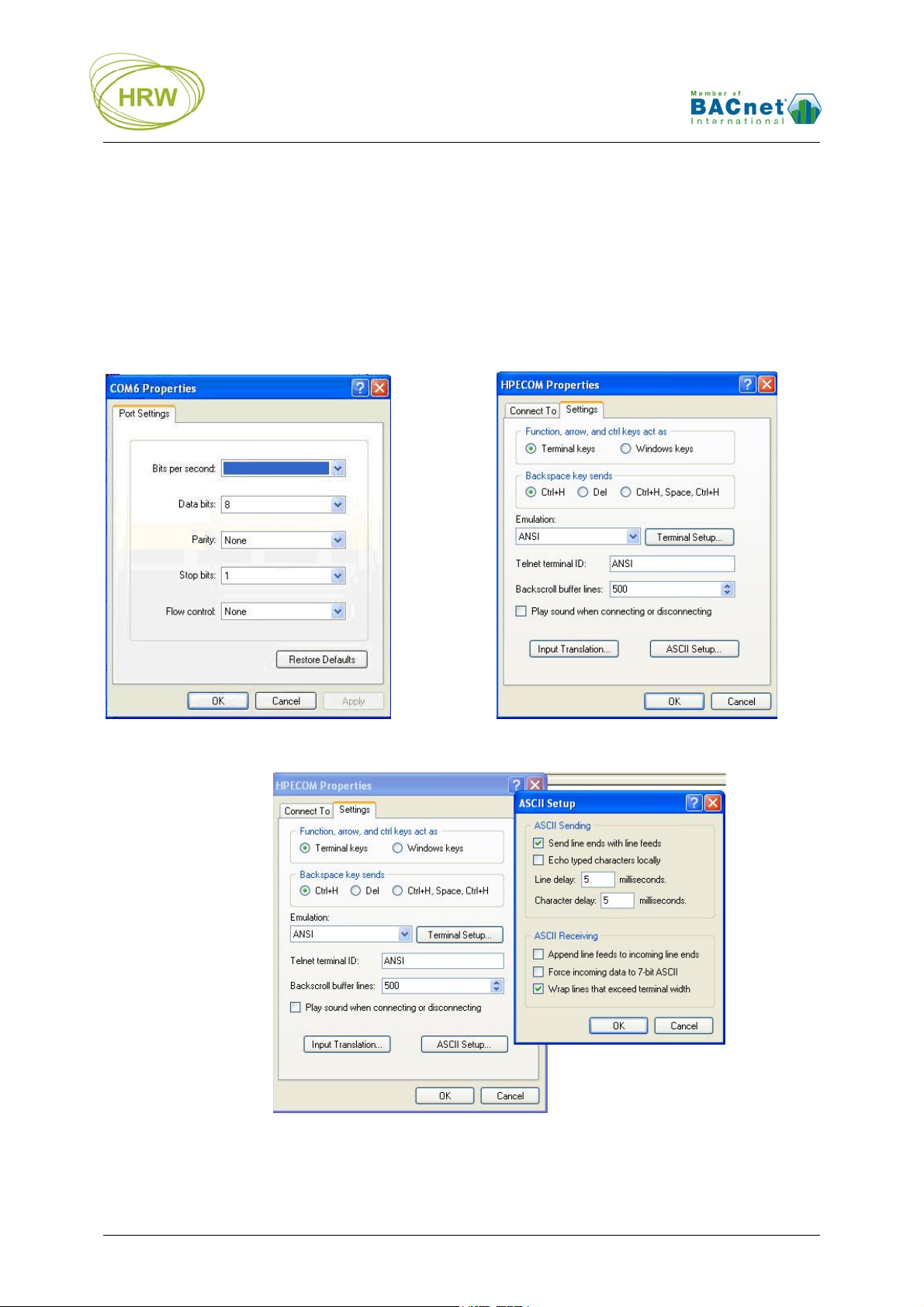
HyperTerminal Settings
For successful communication between HyperTerminal and the device, initial Properties setup of
HyperTerminal should be as per the screen prints below.
‘Connect to’ Comm Configuration: ‘Settings’ General:
9600
‘Settings’ ASCII Setup:
HRW HPE-BNMBUS V401 Manual 180307 E. & O. E. / Subject to change without notice Page 4 of 24

Additional Settings
Some PC platforms may need keyboard response adjustment for initial Terminal Mode success. These
settings may be done via the PC Control Panel >> Keyboard Settings:
Fastest Repeat rate
Shortest Delay time
Fastest Cursor Blink rate
Connecting at 76800 Baud Rate
Because HyperTerminal does not support 76800 baud then after setting to 76800 the device baud rate
will remain at 9600 baud for HyperTerminal communication and switch to 76800 after Writing the new
baud rate and eXiting terminal mode.
To allow later terminal communication a device set with 76800 baud will operate at 9600 baud for the
first 5 seconds after a power-up. If no attempt to connect the terminal at 9600 baud is made within 5
seconds of a power-up then the device will automatically switch to 76800 for normal network operation.
Saving HyperTerminal Settings
For ease of connection it is recommended to save the HyperTerminal setup for each baud rate you may
wish to use with an easily recognised configuration name. For example:
HPECOM 24 (2400)
HPECOM 48 (4800)
HPECOM 96 (9600)
HPECOM 19.2 (19200)
HPECOM 38.4 (38400)
HPECOM 57.6 (57600)
Break in to Terminal Mode
When HyperTerminal is running and the HPECOM cable is connected to the device the initial terminal
screen will be receiving an ASCII character dump which is the BACnet transmission from the device.
The ASCII dump will appear differently with different device address setting and if HyperTerminal baud
rate is different to the baud rate set in the device. Below is an illustration of how the ASCII dump will
look for a device at default settings; address 98 and 9600 baud.
To break in to terminal mode set Caps Lock on and hold the ‘T’ character key continuously
(TTTTTTT…). After five (5) T’s have been sent to the device it will switch to terminal mode. At this point
the BACnet activity on the network will be halted and the device will display the default user screen.
HRW HPE-BNMBUS V401 Manual 180307 E. & O. E. / Subject to change without notice Page 5 of 24

s
)
g
R
r
BACnet Configration Commands
Function Enter Result
Start
communication
Set node address
(MAC)
Set system
Device Instance
Set BACnet
baud rate
Set Maximum
Master address
Set Sys. Vendor
ID
(SysVid)
Zero the Reset
counters
Zero the BACnet
comms error
counter
Zero the M-Bus
comms error
counte
Write values as
default
Exit
communication
TTTTT(TTT…) Break in to Terminal mode
1000=1…98,
100…127
(master)
1000=128…255
(slave)
DI=0…4194303
1001=…
Network node number is
assigned
Unique Device Instance is
assigned
Network comms speed is
set
Highest Master device
MM=1…127
address on the network is
registered
SV=0…255
1=0
2=0
3=0
System vendor specific
features may be available
All Reset counters are
zeroed
BACnet comms error
counter is reset
M-Bus comms error counter
is reset
W Changes written.
Communication with
X
HyperTerminal no longer
active
Options / Comments
With the Caps Lock on, hold the T key down
until the screen updates with HPE data. It is
not necessary to press the enter key to start
communication.
Example: 1000=25
1…98 or 100…127 the device will be a ‘token
passing master’. Note that 99 may not be used.
128… 255 the device will become a network
lave after power reset
Example: DI=401025 (building 4, network 1,
node 25
2400, 4800, 9600, 19200, 38400, 57600,
76800 Example: 1001=38400
After changing comm. speed it will be
necessary to reconnect with HyperTerminal
at the new comm. speed to save (write) the
change!
Next address searching limited to MM
address
SV=0 applies generic BACnet operation. If
an entered ID is not implemented then the
eneric operation will be applied
Factory diag. In order as displayed:
x timeout, Tx timeout, Hardware reset
Example: 2=0
Example: 3=0
Always do this after making changes that
you wish to be permanent
Auto X after 240sec without key entry. After
eXit unplug the HPECOM cable to allow
network communication to take place
HRW HPE-BNMBUS V401 Manual 180307 E. & O. E. / Subject to change without notice Page 6 of 24

M-Bus Configuration Commands
Function Enter Result
Start
communication
Set M-Bus baud
rate
TTTTT(TTT…) Break in to Terminal mode
1002=…
Network comms speed is
set
Options / Comments
With the Caps Lock on, hold the T key down
until the screen updates with HPE data. It is
not necessary to press the enter key to start
communication.
2400, 4800, 9600
Example: 1002=9600
Set Timed Scan
period
Set M-Bus
comms Time Out
Set M-Bus
comms Turnaround time
Prepare for point
data base text file
download
Delete current
point data base
Priority Release
all points to NULL
Priority Release
individual point to
NULL
TS=1…65,000
(minutes)
TO=200…60,000
(msec)
TA=20…1000
(msec)
DE
DE followed by
10000=1
R
R=4…253
Network will be read every
set period in minutes
Retries to a non-responding
meter will be after the set
period, in milliseconds. Skip
after three attempts
The wait time before sending
new commands to a
responding device, in
milliseconds
‘Ready’ will be displayed at
which time the relevant text
file should located and sent
to the gateway
Any configuration of
AV4…AV253 is deleted
All points are Released to
NULL priority
Specified point is Released
to NULL priority
Example: TS=10 (default)
Example: TO=200 (default)
Set in 5ms increments
Example: TA=100 (default)
Set in 5ms increments
Data base lines may also be manually entered,
one by one
Download of a text file with new data base will
delete an old existing data base as a matter of
course
17 will be displayed at the extreme right of
each data point configuration line to signify
NULL priority
17 will be displayed at the extreme right of the
target data point configuration line to signify
NULL priority
Enable M-Bus
subnet
communication
Scroll page
display
Diagnostic
display
Write values as
default
Exit
communication
HRW HPE-BNMBUS V401 Manual 180307 E. & O. E. / Subject to change without notice Page 7 of 24
E
P=1…10
D
W Changes written.
X
Toggles Enabled/Disabled of
M-Bus Subnet
communication
Scroll to specific page if
more data-points are present
than can be displayed on
one screen
Point by point response
codes are displayed each
time ENTER is pressed
Communication with
HyperTerminal no longer
active
Default Disabled to allow easy configuration
when no M-Bus devices are connected. Always
‘Enable’ when M-Bus devices are connected
and points are configured!
Example: P=2
The second page of database settings are
displayed
For data stream analysis between the HPE and
the M-Bus devices. Create text capture file for
easy analysis of the received data stream
Always do this after making changes that
you wish to be permanent
Auto X after 240sec without key entry. After
eXit unplug the HPECOM cable to allow
network communication to take place

M-Bus Reading Structure
Data point search
When an M-Bus device responds to a read request it will provide the data as a series of Response
(RSP) pages. These may be anything from one page to many pages, depending on the number of data
points available from the meter.
To make best use of the available gateway points the gateway will only extract from these pages the
data points that you configure.
Because M-Bus protocol does not enable the gateway to request a specific page or data point then it is
important that the points you require are configured in the gateway in the same sequence as they
appear in the M-Bus device manufacturer’s RSP page/table sequence, otherwise the gateway may
spend unnecessary time searching for data points that have previously been passed in the RSP page
sequence.
Data point address
Each data point in the device pages consists of DIF (Data Information Field) which indicates the data
type (DEC, HEX, BIN, number of data bytes) and one of more VIF (Variable Information Field) which
indicate information such as decimal placement.
In the gateway the DIF must be specified, as minimum criteria, to identify the data point required to be
read. The VIF’s (up to two) may also need to be specified additionally where an identical DIF is used for
more than one data point. This need of VIF definition is particularly true where two data points have
identical DIF value but it is only the subsequent of the two data points having identical DIF that you
want to read.
If both points with identical DIF are required for reading then only the DIF need be defined for both
because the gateway will find the first based on the DIF value and then find the next with same DIF
value as it moves on to search the remaining page records.
When all required points are found the search will end and the gateway will move on to requesting the
next network meter address point in it’s configured point data base
HRW HPE-BNMBUS V401 Manual 180307 E. & O. E. / Subject to change without notice Page 8 of 24
 Loading...